US6500156B1 - Thumb-powered flushing device for catheters - Google Patents
Thumb-powered flushing device for cathetersDownload PDFInfo
- Publication number
- US6500156B1 US6500156B1US09/679,194US67919400AUS6500156B1US 6500156 B1US6500156 B1US 6500156B1US 67919400 AUS67919400 AUS 67919400AUS 6500156 B1US6500156 B1US 6500156B1
- Authority
- US
- United States
- Prior art keywords
- catheter
- chamber
- fluid
- flushing device
- flow
- Prior art date
- Legal status (The legal status is an assumption and is not a legal conclusion. Google has not performed a legal analysis and makes no representation as to the accuracy of the status listed.)
- Expired - Lifetime, expires
Links
Images


Classifications
- A—HUMAN NECESSITIES
- A61—MEDICAL OR VETERINARY SCIENCE; HYGIENE
- A61M—DEVICES FOR INTRODUCING MEDIA INTO, OR ONTO, THE BODY; DEVICES FOR TRANSDUCING BODY MEDIA OR FOR TAKING MEDIA FROM THE BODY; DEVICES FOR PRODUCING OR ENDING SLEEP OR STUPOR
- A61M5/00—Devices for bringing media into the body in a subcutaneous, intra-vascular or intramuscular way; Accessories therefor, e.g. filling or cleaning devices, arm-rests
- A61M5/14—Infusion devices, e.g. infusing by gravity; Blood infusion; Accessories therefor
- A61M5/142—Pressure infusion, e.g. using pumps
- A61M5/14212—Pumping with an aspiration and an expulsion action
- A61M5/1424—Manually operated pumps
- A—HUMAN NECESSITIES
- A61—MEDICAL OR VETERINARY SCIENCE; HYGIENE
- A61M—DEVICES FOR INTRODUCING MEDIA INTO, OR ONTO, THE BODY; DEVICES FOR TRANSDUCING BODY MEDIA OR FOR TAKING MEDIA FROM THE BODY; DEVICES FOR PRODUCING OR ENDING SLEEP OR STUPOR
- A61M5/00—Devices for bringing media into the body in a subcutaneous, intra-vascular or intramuscular way; Accessories therefor, e.g. filling or cleaning devices, arm-rests
- A61M5/14—Infusion devices, e.g. infusing by gravity; Blood infusion; Accessories therefor
- A61M2005/1401—Functional features
- A61M2005/1403—Flushing or purging
Definitions
- the present inventionrelates generally to the field of devices for flushing catheters. More specifically, the present invention discloses a thumb-powered flushing device for intravenous catheters.
- Intravenous cathetershave been widely used for many years to administer medications and other fluids to patients.
- medicationis administered through the catheter on a continuous basis.
- doses of medicationare administered on a periodic basis.
- Patients undergoing long-term drug therapiesi.e., a few to several weeks
- One of the biological reactions of the body to an implanted catheteris a growth of dendrites or filaments into the end of the catheter.
- an important aspect of this processis maintaining an open, free-flowing catheter.
- saline solution or other fluidtypically in the range of approximately 0.1 to 5.0 ml/hr
- KVOkeep vein open
- the KVO infusioncan be provided by an electronic pump, disposable infuser, or an IV drip.
- the IV line attached to the KVO devicetypically terminates in an injection site (e.g., a Y-site as illustrated in FIG. 1) at the patient.
- a Y-siteone branch of the Y-site has a rubber seal that permits medication or other fluids to be injected from a syringe through the rubber seal and into the catheter, without the need to disconnect the KVO flow.
- the KVO flowis sometimes insufficient to maintain patency of the catheter. Therefore, many healthcare professionals inject a quantity of saline solution (about 3 ml) via syringe through the rubber seal of the Y-site to ensure patency of the catheter prior to administering each dose of medication. Several of these flushes may be required each day, usually just prior to injections of medication. This approach is effective, but adds time and expense to the procedure.
- Cole et al.disclose a catheter flushing device with a valve plunger having a capillary passage that provides a first low-flow path. When the plunger is moved from its seat, a second high-flow path is established that flushes the apparatus. Stevens discloses a similar device.
- Reynolds et al.disclose a flush device for an intravenous blood pressure monitoring system that includes a continuous flow channel and a fast flush channel.
- the flush devicehas a generally tubular housing containing a plunger surrounded by an elastomeric member.
- the elastomeric memberWhen the plunger is in its raised position, the elastomeric member is relaxed and restricts flow through the housing to a small capillary channel.
- the plungeris depressed, the elastomeric member stretches and creates a larger channel for fluid flow between the elastomeric member and the interior surface of the housing, which permits a fast flush flow through the device.
- Steigerwald, Hubbard et al., and Ledisclose other examples of catheter flushing devices with push-button valve mechanisms that provide both slow flow and fast flush modes.
- Bryant et al.disclose an ambulatory infusion system having a gas-pressurized bladder to discharge solution from an adjacent bag. Internal gas pressure is developed within the bladder by a chemical reaction.
- the tubing set leading from the solution bagincludes a flow restrictor that can be sized to provide minimal flow rates.
- a catheter flushing deviceusing a thumb-powered movable member (e.g., a flexible diaphragm) to propel fluid through the catheter, and a valve that regulates flow into and out of the chamber beneath the movable member.
- a thumb-powered movable membere.g., a flexible diaphragm
- the present devicecan be used to deliver a small quantity of fluid to flush a catheter, or alternatively can be used to deliver a bolus of medication.
- the present devicecan also be used to provide a continuous low-volume flow (i.e., a KVO flow) to the catheter between doses.
- This inventionprovides a catheter flushing device that includes a chamber covered with a movable member (e.g., a flexible diaphragm) that can be compressed by exertion of pressure on the movable member; and a valve having a first position allowing fluid from a fluid source to fill the chamber, and a second position allowing fluid from the chamber to flow through the catheter when pressure is exerted on the movable member.
- the catheter flushing deviceincludes a housing having a cylindrical valve opening, an inlet port for connection with the fluid source, and an outlet port for connection with the catheter.
- the chamberis defined by a movable member sealed to a region of the housing. The chamber can be compressed by manually exerting pressure on the movable member by means of a thumb or finger.
- a passagewayextends through the housing from the chamber to the valve opening.
- a rotatable valve member within the valve openinghas a channel directing fluid from the inlet port into the chamber in the first position, and a channel directing fluid from the chamber to the outlet port in the second position.
- the devicecan also be equipped with a KVO flow path through the housing between the inlet and outlet ports to maintain a substantially constant, minimal flow from the fluid source to the catheter that bypasses the valve assembly.
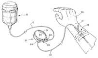
- FIG. 1is a perspective view of the present device 20 connected in the tubing between an infusion pump 10 and a catheter 15 .
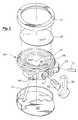
- FIG. 2is an exploded perspective view of the present device 20 .
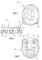
- FIG. 3is a top view of the housing of the device.
- FIG. 4is an end view of the housing of the device corresponding to FIG. 3 .
- FIG. 5is a bottom view of the housing of the device with the bottom cover removed.
- FIG. 6is horizontal cross-sectional view of the device with the valve in a first position allowing fluid from the infusion pump to flow into the chamber beneath the diaphragm.
- FIG. 7is a vertical cross-sectional view of the device corresponding to FIG. 6 .
- FIG. 8is a horizontal cross-sectional view of the device with the valve in a second position allowing fluid from the chamber to be delivered to the catheter by exerting pressure on the diaphragm.
- FIG. 9is a vertical cross-sectional view of the device corresponding to FIG. 8 .
- FIG. 10is a horizontal cross-sectional view of the device with the valve in an intermediate position allowing only KVO flow.
- FIG. 11is a vertical cross-sectional view of the device corresponding to FIG. 10 .
- FIG. 1a perspective view is provided showing the present device 20 connected in the tubing between an infusion pump 10 and a catheter 15 .
- Any type of infusion pumpcan be employed as a source of fluid to be administered to the patient 50 via the catheter 15 .
- fluidcan be supplied by gravity from an elevated IV bag.
- Conventional fluid sourcesdeliver fluid at a pressure of approximately 6 psi, although the present device will work satisfactory at pressures ranging down to approximately 1 to 1.5 psi.
- any type of catheter 15can be used.
- the drawingsillustrate a conventional intravenous catheter 15 inserted into a vein in the hand of a patient 50 .
- the proximal portion of the catheter 15includes a injection site 17 .
- the injection site 17can be a Y-site having a first branch that can be connected to the fluid source 10 , and a second branch with a resilient cap that can be used for injection of medication from a syringe.
- cathetershould be interpreted to include any type of device having a lumen for delivering medication or other fluids to any part of a patient, or for draining fluid from a patient. This includes, but is not limited to intravenous catheters, injection sites, vascular access devices, transtracheal catheters, endotracheal tubes, and catheters used for delivery of anesthetics.
- the present device 20has a housing with an inlet port 22 that can be connected to the tube 12 leading from the infusion pump 10 , and outlet port 24 that can be connected to the tube 14 leading to the catheter 15 . Both ports 22 , 24 lead to a generally cylindrical valve opening 21 that extends inward from one edge of the device housing 20 as shown in FIG. 2 .
- FIG. 3is a top view of the device housing 20 .
- FIG. 4is an end view of the device housing 20 corresponding to FIG. 3 .
- FIG. 5is a bottom view of the device housing 20 with the bottom cover removed.
- a movable member 30(e.g., a flexible diaphragm) is sealed about a region of the device housing 20 to define a fluid storage chamber 28 between the surface of the housing 20 and the movable member 30 as shown in FIG. 7 .
- a diaphragm 30can be secured to the housing 20 by means of a retaining ring 31 that clips over a raised flange on the housing 20 , as depicted in the exploded perspective view provided in FIG. 2 .
- the fluid storage chamber 28is connected to the cylindrical valve opening 21 by a small passageway 27 extending through the device housing 20 that permits fluid to flow into and out of the chamber 28 via the valve opening 21 .
- the fluid storage chamber 28can be compressed by manually exerting pressure on the movable member 30 by means of a thumb or finger. This causes fluid to flow from the chamber 28 through the passageway 27 and into the valve opening 21 .
- the movable member 30could be a piston, bellows, or movable button.
- a rotatable valve member 32is inserted into the valve opening 21 .
- the valve member 32has an external handle 35 that provides a finger-grip for turning the valve member 32 with respect to the device housing 20 and valve opening 21 .
- the distal portion of the valve member 32 that is inserted into the valve opening 21has a generally complementary shape (i.e., a cylindrical or tapered cylindrical shape) to maintain a fluid-tight seal.
- the surface of the valve member 32also includes a first channel 33 (FIG. 6) that directs fluid from the inlet port 22 into the fluid storage chamber 28 when the valve member 32 is in a first rotational position with respect to the valve opening 21 , and a second channel 34 (FIG.
- both channels 33 and 34could be accomplished by a single channel that rotates from alignment with the inlet port 22 in the first rotational position, to alignment with the outlet port 24 in the second rotational position.
- the passageway 27 leading to the fluid storage chamber 28is located near the distal end of the valve opening 21 .
- the valve member 32does not extend all of the way to the distal end of the valve opening 21 , thereby leaving an enclosed region between the distal end of the valve member and distal end of the valve opening 21 . This is shown most clearly in FIGS. 6, 8 , and 10 .
- fluidflows along one of the channels 33 , 34 , though the enclosed region at the distal end of the valve opening, and through the passageway 27 leading to the fluid storage chamber 28 .
- this two-position valve assemblyprovides significant safety advantages.
- the valve member 32When the valve member 32 is in the first rotational position (i.e., the “fill” position), fluid is only permitted to flow from the fluid source 10 into the fluid storage chamber 28 .
- the valve assemblyprevents backflow from the patient 50 into the device 20 , and also blocks uncontrolled forward flow from the fluid pump 10 to the patient 50 through the device 20 .
- the valve assemblyprevents backflow from the fluid storage chamber 28 to the fluid pump 10 , and also blocks uncontrolled forward flow form the fluid pump 10 to the patient 50 through the device 20 .
- valve member 32When the valve member 32 is moved to intermediate position between the “fill” and “flush” position, no fluid flow is allowed into or out of the fluid storage chamber 28 , or through the valve assembly.
- the present devicecan also be equipped with a KVO flow path 26 between the inlet and outlet ports 22 , 24 to maintain a substantially constant, minimal flow (i.e., KVO flow) from the fluid source 10 to the catheter 15 .
- KVO flowa substantially constant flow
- a loop of plastic tubing 26 having a very small diameter boreextends from the inlet port 22 to the outlet port 24 and completely bypasses the valve assembly 21 , 32 regardless of the position of the valve member 32 .
- the small bore of the KVO tubing 26serves as a severe flow restriction that limits total flow along the KVO flow path to a fraction of a milliliter per hour.
- the present device 20can also be equipped with one-way valves 23 , 25 and the inlet and outlet ports 22 , 24 , respectively, to prevent backflow, as shown in FIGS. 6, 8 , and 10 .
- the one-way valve 23 at the inlet port 22allows flow from the fluid source 10 into the device 20 , but prevents backflow from the catheter 15 or fluid storage chamber 28 .
- the one-way valve 25 at the outlet port 24allows flow from the fluid storage chamber 28 to the catheter 15 , but prevents backflow from the catheter 15 or the KVO flow path into the fluid storage chamber 28 .
- a contoured bottom cover 40attaches to the rear of the device housing 20 and encloses the KVO tubing 26 and one-way valves 23 , 25 to maintain structural integrity of the device and prevent contamination.
- the surface of the housing 20 beneath the diaphragm 30includes a small bump 29 as illustrated in FIG. 2 .
- the bump 29eventually comes into contact with the underside of the diaphragm and provides a tactile indication to the user's thumb or finger that the fluid storage chamber 28 is empty.
- FIG. 6is a horizontal cross-sectional view of the device 20 with the valve member 32 in a “fill” position allowing fluid from the infusion pump to fill the chamber 28 beneath the movable member 30 .
- FIG. 7A corresponding vertical cross-sectional view of the device in the “fill” state is shown in FIG. 7 .
- FIG. 8is a horizontal cross-sectional view of the device 20 with the valve member 32 in the “flush” position allowing fluid from the chamber 28 to be delivered to the catheter 15 by exerting pressure on the movable member 30 .
- a corresponding vertical cross-sectional view of the device in the “flush” stateis shown in FIG. 9 .
- the second channel 34 on the valve member 32is rotated into alignment with the outlet port 24 so that fluid flows from the chamber 28 through the passageway 27 and outlet port 22 to the catheter 15 .
- the movable member 30is gradually depressed as fluid exits the chamber 28 . Flow may continue until the chamber 28 has completely collapsed against the surface of the device housing 20 as depicted in FIG. 9 .
- the raised bump 29 on the surface of the device housing 20can be felt through the diaphragm 30 and signals the user that flushing is complete.
- This processing of filling and flushingcan be rapidly repeated as many times as necessary to deliver a series of surges of fluid through the catheter 15 .
- the fluid storage chamberwill automatically fill rapidly with fluid after the valve member 32 is rotated to the “fill” position.
- the valve member 32can then easily rotated to the “flush” position.
- the flow rate exiting the fluid storage chamber 28is controlled by the pressure exerted by the user on diaphragm 30 .
- a safety featureit should be noted that uncontrolled forward flow cannot result, regardless of the position of the valve member 32 .
- FIGS. 10 and 11are corresponding orthogonal cross-sectional views of the present device with the valve handle 35 in an intermediate position to allow only KVO flow.
- the valve handle 35In the “KVO” state, neither of the channels 33 or 34 are aligned to allow flow through the device 20 , or into or out of the fluid storage chamber 28 .
- the only flow to the catheter 15is the nominal KVO flow through the KVO tube 26 .
- the device 20can be kept with the valve handle 35 in the “flush” position to continue to provide a KVO flow, since the one-way valve 25 at the outlet port 24 prevents backflow from the catheter 15 .
- the present inventionprovides a completely enclosed fluid path from the fluid pump 10 to the patient 50 . This helps to reduce the risk of infection, contamination, or other intravenous complications.
- the device 20is separated from the injection site by a length of flexible tubing, which greatly reduces mechanical stress on the injection site and patient discomfort.
- the device 20can be employed to administer a bolus of medication as well as bolus basal medication.
- the device 20can be used as a means for administering a dose of analgesic medication on demand over time.
- the dosageis determined by the maximum volume of the fluid storage chamber 28 .
- the present devicecan also be used to insert a medication spacer (e.g., saline solution or other patency fluid) between doses of incompatible medications.
Landscapes
- Health & Medical Sciences (AREA)
- Vascular Medicine (AREA)
- Engineering & Computer Science (AREA)
- Anesthesiology (AREA)
- Biomedical Technology (AREA)
- Heart & Thoracic Surgery (AREA)
- Hematology (AREA)
- Life Sciences & Earth Sciences (AREA)
- Animal Behavior & Ethology (AREA)
- General Health & Medical Sciences (AREA)
- Public Health (AREA)
- Veterinary Medicine (AREA)
- Infusion, Injection, And Reservoir Apparatuses (AREA)
Abstract
Description
| Inventor | Patent No. | Issue Date | ||
| Cole et al. | 4,291,702 | Sep. 29, 1981 | ||
| Stevens | 4,341,224 | July 27, 1982 | ||
| Steigerwald | 4,457,487 | July 3, 1984 | ||
| Hubbard et al. | 4,497,468 | Feb. 5, 1985 | ||
| Le | 4,624,662 | Nov. 25, 1986 | ||
| Reynolds et al. | 5,678,557 | Oct. 21, 1997 | ||
| Bryant et al. | 5,738,657 | Apr. 14, 1998 | ||
Claims (12)
Priority Applications (1)
| Application Number | Priority Date | Filing Date | Title |
|---|---|---|---|
| US09/679,194US6500156B1 (en) | 2000-10-03 | 2000-10-03 | Thumb-powered flushing device for catheters |
Applications Claiming Priority (1)
| Application Number | Priority Date | Filing Date | Title |
|---|---|---|---|
| US09/679,194US6500156B1 (en) | 2000-10-03 | 2000-10-03 | Thumb-powered flushing device for catheters |
Publications (1)
| Publication Number | Publication Date |
|---|---|
| US6500156B1true US6500156B1 (en) | 2002-12-31 |
Family
ID=24725935
Family Applications (1)
| Application Number | Title | Priority Date | Filing Date |
|---|---|---|---|
| US09/679,194Expired - LifetimeUS6500156B1 (en) | 2000-10-03 | 2000-10-03 | Thumb-powered flushing device for catheters |
Country Status (1)
| Country | Link |
|---|---|
| US (1) | US6500156B1 (en) |
Cited By (22)
| Publication number | Priority date | Publication date | Assignee | Title |
|---|---|---|---|---|
| US20040181192A1 (en)* | 2003-03-11 | 2004-09-16 | Cuppy Michael John | Vascular access device and method of using same |
| US20050113766A1 (en)* | 2003-11-26 | 2005-05-26 | Jim Mottola | Primer bulb for contrast media delivery system |
| US20060122562A1 (en)* | 2004-11-19 | 2006-06-08 | Mckinley Medical L.L.L.P. | Controlled-volume infusion device |
| US20060129111A1 (en)* | 2004-12-09 | 2006-06-15 | Mottola Jim D | Burette float and drainage aperture |
| US20060264850A1 (en)* | 2004-12-09 | 2006-11-23 | Merit Medical Systems, Inc. | Valve assembly with chamber vent and fluid deflector |
| WO2007133061A1 (en)* | 2006-05-15 | 2007-11-22 | Mecha-Medic Solution Sdn. Bhd. | Intravenous drip set controller with flusher |
| US20090259199A1 (en)* | 2008-04-14 | 2009-10-15 | Lampropoulos Fred P | Contrast media diffusion system |
| US20100057015A1 (en)* | 2008-09-03 | 2010-03-04 | Ace Medical Co., Ltd. | Medicinal liquid supply apparatus having fixed-type medicinal liquid supply volume controller and arbitrary medicinal liquid supply volume controller |
| US20100076370A1 (en)* | 2008-09-23 | 2010-03-25 | Infusion Advancements, LLC. | Apparatus and methods for purging catheter systems |
| US20100249717A1 (en)* | 2009-03-30 | 2010-09-30 | Lifemedix, Llc | Manual pump for intravenous fluids |
| US20100305508A1 (en)* | 2009-05-27 | 2010-12-02 | Cardinal Health 303, Inc. | Intravenous piston pump disposable & mechanism |
| WO2012044388A1 (en)* | 2010-10-01 | 2012-04-05 | Smiths Medical Asd, Inc. | Flushing a fluid line from a medical pump |
| US20120197199A1 (en)* | 2011-01-28 | 2012-08-02 | Calibra Medical, Inc. | Detachable drug delivery device |
| US20130110038A1 (en)* | 2011-10-31 | 2013-05-02 | Chia-Yu Hsu | Infusion apparatus and countercurrent pushback infusion apparatus |
| US8545451B2 (en) | 2009-03-30 | 2013-10-01 | Lifemedix Statfusion, Llc | Manual pump for intravenous fluids |
| JP2016514569A (en)* | 2013-04-03 | 2016-05-23 | ベクトン・ディキンソン・アンド・カンパニーBecton, Dickinson And Company | Modified intravenous tubing set for inline catheter flushing |
| EP3160540A4 (en)* | 2014-06-27 | 2018-03-14 | Bayer Healthcare LLC | Inline patency check device |
| US10881784B2 (en) | 2013-01-28 | 2021-01-05 | Smiths Medical Asd, Inc. | Medication safety devices and methods |
| CN113559357A (en)* | 2020-04-29 | 2021-10-29 | 康尔福盛303公司 | Infusion flow control device for maintaining vein patency |
| US11224692B2 (en) | 2010-10-01 | 2022-01-18 | Smiths Medical Asd, Inc. | Flushing a fluid line from a medical pump |
| US20220347383A1 (en)* | 2015-05-14 | 2022-11-03 | Carefusion 303, Inc. | Priming apparatus and method |
| WO2024063931A1 (en)* | 2022-09-23 | 2024-03-28 | Carefusion 303, Inc. | Reusable fluid pumping device |
Citations (15)
| Publication number | Priority date | Publication date | Assignee | Title |
|---|---|---|---|---|
| US1988624A (en)* | 1933-08-08 | 1935-01-22 | Ralph P Kipp | Blood transfusion device |
| US2071127A (en)* | 1935-04-29 | 1937-02-16 | Josiah L Jones | Venereal air syringe |
| US2471623A (en)* | 1944-12-19 | 1949-05-31 | Adrian O Hubbell | Apparatus for handling fluids |
| US4291702A (en) | 1979-06-25 | 1981-09-29 | Gould Inc. | Catheter flushing apparatus |
| US4341224A (en) | 1980-02-04 | 1982-07-27 | Gould Inc. | Catheter flushing apparatus |
| US4457487A (en) | 1982-06-23 | 1984-07-03 | The Kendall Company | Flushing device |
| US4497468A (en) | 1982-04-26 | 1985-02-05 | Graphic Controls Corporation | Catheter patency flush flow controller |
| US4624662A (en) | 1982-11-24 | 1986-11-25 | Transamerica Delaval Inc. | Catheter flushing systems |
| US5061243A (en)* | 1985-08-06 | 1991-10-29 | Baxter International Inc. | System and apparatus for the patient-controlled delivery of a beneficial agent, and set therefor |
| US5267964A (en)* | 1992-03-23 | 1993-12-07 | Clintec Nutrition Co. | Fluid control device including automatic valve |
| US5389070A (en)* | 1993-03-16 | 1995-02-14 | Wake Forest University | Syringe apparatus with a fluid reservoir for injection and aspiration of fluids |
| US5588816A (en)* | 1993-05-26 | 1996-12-31 | Quest Medical, Inc. | Disposable cassette for cardioplegia delivery system |
| US5678557A (en) | 1993-12-23 | 1997-10-21 | Abbott Laboratories | One hand push button intraflo |
| US5738657A (en) | 1992-06-15 | 1998-04-14 | Abbott Laboratories | Ambulatory energized container system |
| US6315762B1 (en)* | 1996-11-14 | 2001-11-13 | Angiodynamics, Inc. | Contrast medium delivery system and associated method |
- 2000
- 2000-10-03USUS09/679,194patent/US6500156B1/ennot_activeExpired - Lifetime
Patent Citations (15)
| Publication number | Priority date | Publication date | Assignee | Title |
|---|---|---|---|---|
| US1988624A (en)* | 1933-08-08 | 1935-01-22 | Ralph P Kipp | Blood transfusion device |
| US2071127A (en)* | 1935-04-29 | 1937-02-16 | Josiah L Jones | Venereal air syringe |
| US2471623A (en)* | 1944-12-19 | 1949-05-31 | Adrian O Hubbell | Apparatus for handling fluids |
| US4291702A (en) | 1979-06-25 | 1981-09-29 | Gould Inc. | Catheter flushing apparatus |
| US4341224A (en) | 1980-02-04 | 1982-07-27 | Gould Inc. | Catheter flushing apparatus |
| US4497468A (en) | 1982-04-26 | 1985-02-05 | Graphic Controls Corporation | Catheter patency flush flow controller |
| US4457487A (en) | 1982-06-23 | 1984-07-03 | The Kendall Company | Flushing device |
| US4624662A (en) | 1982-11-24 | 1986-11-25 | Transamerica Delaval Inc. | Catheter flushing systems |
| US5061243A (en)* | 1985-08-06 | 1991-10-29 | Baxter International Inc. | System and apparatus for the patient-controlled delivery of a beneficial agent, and set therefor |
| US5267964A (en)* | 1992-03-23 | 1993-12-07 | Clintec Nutrition Co. | Fluid control device including automatic valve |
| US5738657A (en) | 1992-06-15 | 1998-04-14 | Abbott Laboratories | Ambulatory energized container system |
| US5389070A (en)* | 1993-03-16 | 1995-02-14 | Wake Forest University | Syringe apparatus with a fluid reservoir for injection and aspiration of fluids |
| US5588816A (en)* | 1993-05-26 | 1996-12-31 | Quest Medical, Inc. | Disposable cassette for cardioplegia delivery system |
| US5678557A (en) | 1993-12-23 | 1997-10-21 | Abbott Laboratories | One hand push button intraflo |
| US6315762B1 (en)* | 1996-11-14 | 2001-11-13 | Angiodynamics, Inc. | Contrast medium delivery system and associated method |
Cited By (56)
| Publication number | Priority date | Publication date | Assignee | Title |
|---|---|---|---|---|
| US20040181192A1 (en)* | 2003-03-11 | 2004-09-16 | Cuppy Michael John | Vascular access device and method of using same |
| US20050113766A1 (en)* | 2003-11-26 | 2005-05-26 | Jim Mottola | Primer bulb for contrast media delivery system |
| EP1812096A4 (en)* | 2004-11-19 | 2008-06-04 | Curlin Medical Inc | Controlled-volume infusion device |
| US20060122562A1 (en)* | 2004-11-19 | 2006-06-08 | Mckinley Medical L.L.L.P. | Controlled-volume infusion device |
| US8372045B2 (en) | 2004-11-19 | 2013-02-12 | Curlin Medical Inc. | Controlled-volume infusion device |
| US20060129111A1 (en)* | 2004-12-09 | 2006-06-15 | Mottola Jim D | Burette float and drainage aperture |
| US20060264850A1 (en)* | 2004-12-09 | 2006-11-23 | Merit Medical Systems, Inc. | Valve assembly with chamber vent and fluid deflector |
| US7879014B2 (en) | 2004-12-09 | 2011-02-01 | Merit Medical Systems, Inc. | Valve assembly with chamber vent and fluid deflector |
| US7731699B2 (en) | 2004-12-09 | 2010-06-08 | Merit Medical Systems, Inc. | Burette float and drainage aperture |
| WO2007133061A1 (en)* | 2006-05-15 | 2007-11-22 | Mecha-Medic Solution Sdn. Bhd. | Intravenous drip set controller with flusher |
| CN101443060B (en)* | 2006-05-15 | 2011-09-28 | 机械医疗方案公司 | Intravenous drip device controller having flusher |
| US20090259199A1 (en)* | 2008-04-14 | 2009-10-15 | Lampropoulos Fred P | Contrast media diffusion system |
| US8568368B2 (en) | 2008-04-14 | 2013-10-29 | Merit Medical Systems, Inc. | Contrast media diffusion system |
| US20100057015A1 (en)* | 2008-09-03 | 2010-03-04 | Ace Medical Co., Ltd. | Medicinal liquid supply apparatus having fixed-type medicinal liquid supply volume controller and arbitrary medicinal liquid supply volume controller |
| US7905865B2 (en)* | 2008-09-03 | 2011-03-15 | Ace Medical Co., Ltd. | Medicinal liquid supply apparatus having fixed-type medicinal liquid supply volume controller and arbitrary medicinal liquid supply volume controller |
| US11266790B2 (en) | 2008-09-23 | 2022-03-08 | Becton, Dickinson And Company | Apparatus and methods for purging catheter systems |
| US9889289B2 (en) | 2008-09-23 | 2018-02-13 | Becton, Dickinson And Company | Apparatus and methods for purging catheter systems |
| US20100076370A1 (en)* | 2008-09-23 | 2010-03-25 | Infusion Advancements, LLC. | Apparatus and methods for purging catheter systems |
| US11964139B2 (en) | 2008-09-23 | 2024-04-23 | Becton, Dickinson And Company | Apparatus and methods for purging catheter systems |
| US10561796B2 (en) | 2008-09-23 | 2020-02-18 | Beckton, Dickinson And Company | Apparatus and methods for purging catheter systems |
| US20100249717A1 (en)* | 2009-03-30 | 2010-09-30 | Lifemedix, Llc | Manual pump for intravenous fluids |
| US8337466B2 (en) | 2009-03-30 | 2012-12-25 | Lifemedix, Llc | Manual pump for intravenous fluids |
| US8545451B2 (en) | 2009-03-30 | 2013-10-01 | Lifemedix Statfusion, Llc | Manual pump for intravenous fluids |
| US9220836B2 (en) | 2009-03-30 | 2015-12-29 | Lifemedix Statfusion, Llc | Portable pump for intravenous fluids |
| WO2010132290A3 (en)* | 2009-05-09 | 2011-01-06 | Becton, Dickinson And Company | Apparatus for purging catheter systems |
| CN102481408A (en)* | 2009-05-27 | 2012-05-30 | 康尔福盛303公司 | Disposable intravenous injection piston pump and mechanism |
| US20100305508A1 (en)* | 2009-05-27 | 2010-12-02 | Cardinal Health 303, Inc. | Intravenous piston pump disposable & mechanism |
| CN102481408B (en)* | 2009-05-27 | 2015-04-01 | 康尔福盛303公司 | Disposable intravenous piston pump and mechanism |
| WO2010138612A3 (en)* | 2009-05-27 | 2011-04-14 | Carefusion 303, Inc. | Intravenous piston pump disposable and mechanism |
| US9566385B2 (en) | 2009-05-27 | 2017-02-14 | Carefusion 303, Inc. | Intravenous piston pump disposable and mechanism |
| US8733736B2 (en) | 2009-05-27 | 2014-05-27 | Carefusion 303, Inc. | Intravenous piston pump disposable and mechanism |
| RU2552683C2 (en)* | 2009-05-27 | 2015-06-10 | Кэафьюжн 303, Инк. | Disposable piston pump and mechanism for intravenous infusion |
| US10143800B2 (en) | 2010-10-01 | 2018-12-04 | Smiths Medical Asd, Inc. | Flushing a fluid line from a medical pump |
| US11224692B2 (en) | 2010-10-01 | 2022-01-18 | Smiths Medical Asd, Inc. | Flushing a fluid line from a medical pump |
| AU2014202910B2 (en)* | 2010-10-01 | 2016-01-28 | Icu Medical, Inc. | Flushing a fluid line from a medical pump |
| US12064596B2 (en) | 2010-10-01 | 2024-08-20 | Smiths Medical Asd, Inc. | Flushing a fluid line from a medical pump |
| WO2012044388A1 (en)* | 2010-10-01 | 2012-04-05 | Smiths Medical Asd, Inc. | Flushing a fluid line from a medical pump |
| CN103189082A (en)* | 2010-10-01 | 2013-07-03 | 史密斯医疗Asd公司 | Flush the fluid line with a medical pump |
| US8876793B2 (en) | 2010-10-01 | 2014-11-04 | Smiths Medical Asd, Inc. | Flushing a fluid line from a medical pump |
| US8696630B2 (en)* | 2011-01-28 | 2014-04-15 | Calibra Medical, Inc. | Detachable drug delivery device |
| CN103619382B (en)* | 2011-01-28 | 2016-07-06 | 凯利宝医疗公司 | Detachable Drug Delivery Device |
| CN103619382A (en)* | 2011-01-28 | 2014-03-05 | 凯利宝医疗公司 | Detachable drug delivery device |
| KR20140022800A (en)* | 2011-01-28 | 2014-02-25 | 캘리브라 메디컬 인코포레이티드 | Detachable drug delivery device |
| US20120197199A1 (en)* | 2011-01-28 | 2012-08-02 | Calibra Medical, Inc. | Detachable drug delivery device |
| US20130110038A1 (en)* | 2011-10-31 | 2013-05-02 | Chia-Yu Hsu | Infusion apparatus and countercurrent pushback infusion apparatus |
| US10881784B2 (en) | 2013-01-28 | 2021-01-05 | Smiths Medical Asd, Inc. | Medication safety devices and methods |
| JP2016514569A (en)* | 2013-04-03 | 2016-05-23 | ベクトン・ディキンソン・アンド・カンパニーBecton, Dickinson And Company | Modified intravenous tubing set for inline catheter flushing |
| EP3160540A4 (en)* | 2014-06-27 | 2018-03-14 | Bayer Healthcare LLC | Inline patency check device |
| US20220347383A1 (en)* | 2015-05-14 | 2022-11-03 | Carefusion 303, Inc. | Priming apparatus and method |
| US11944782B2 (en)* | 2015-05-14 | 2024-04-02 | Carefusion 303, Inc. | Priming apparatus and method |
| WO2021222303A3 (en)* | 2020-04-29 | 2021-12-09 | Carefusion 303, Inc. | Keep vein open infusion flow control device |
| CN113559357A (en)* | 2020-04-29 | 2021-10-29 | 康尔福盛303公司 | Infusion flow control device for maintaining vein patency |
| US11400210B2 (en)* | 2020-04-29 | 2022-08-02 | Carefusion 303, Inc. | Keep vein open infusion flow control device |
| US20220323673A1 (en)* | 2020-04-29 | 2022-10-13 | Carefusion 303, Inc. | Keep vein open infusion flow control device |
| US12364812B2 (en)* | 2020-04-29 | 2025-07-22 | Carefusion 303, Inc. | Keep vein open infusion flow control device |
| WO2024063931A1 (en)* | 2022-09-23 | 2024-03-28 | Carefusion 303, Inc. | Reusable fluid pumping device |
Similar Documents
| Publication | Publication Date | Title |
|---|---|---|
| US6500156B1 (en) | Thumb-powered flushing device for catheters | |
| US5267964A (en) | Fluid control device including automatic valve | |
| EP0563324B1 (en) | Drug infusion manifold | |
| US20080004574A1 (en) | Selectable rate intravenous infusion set | |
| US4813937A (en) | Ambulatory disposable infusion delivery system | |
| US5807312A (en) | Bolus pump apparatus | |
| US5188603A (en) | Fluid infusion delivery system | |
| US5439452A (en) | Limit stop valve infusion device | |
| US5127904A (en) | Improved needle-less parenteral fluid injector | |
| EP1527794B1 (en) | Refill kit for an implantable pump | |
| US5356379A (en) | Disposable ambulatory infusion pump assembly | |
| US6059747A (en) | Syringe pump infusion control set | |
| EP0592483B1 (en) | Apparatus for patient-controlled infusion | |
| US20050245883A1 (en) | Apparatus and method for administration of IV liquid medication and IV flush solutions | |
| US20020019608A1 (en) | Patient-controlled medication delivery system with overmedication prevention | |
| US7975721B2 (en) | Fluid valve systems | |
| EP0231371A1 (en) | PATIENT CONTROLLED ADMINISTRATIVE ADMINISTRATION. | |
| NL8403937A (en) | DEVICE FOR DELIVERING A NUMBER OF LIQUID DOSES. | |
| CN100462110C (en) | Infusion Tubing and Infusion Tubing Components | |
| EP3669909B1 (en) | Medical liquid administration device | |
| US5217432A (en) | Automated drug infusion manifold | |
| US4904243A (en) | Device for self-administration of drugs or the like | |
| US20110245779A1 (en) | Fluid Valve Systems | |
| WO1993025262A1 (en) | Dual access catheter for implantable pump system | |
| KR200240026Y1 (en) | Medical instrumetnt for prevention of a counter current and air |
Legal Events
| Date | Code | Title | Description |
|---|---|---|---|
| AS | Assignment | Owner name:MCKINLEY MEDICAL L.L.L.P., COLORADO Free format text:ASSIGNMENT OF ASSIGNORS INTEREST;ASSIGNOR:DEAN, STANSBURY L.;REEL/FRAME:011192/0762 Effective date:20000926 | |
| FEPP | Fee payment procedure | Free format text:PAYOR NUMBER ASSIGNED (ORIGINAL EVENT CODE: ASPN); ENTITY STATUS OF PATENT OWNER: LARGE ENTITY | |
| STCF | Information on status: patent grant | Free format text:PATENTED CASE | |
| FPAY | Fee payment | Year of fee payment:4 | |
| AS | Assignment | Owner name:MCKINLEY MEDICAL, LLC, COLORADO Free format text:CERTIFICATE OF CONVERSION;ASSIGNOR:MCKINLEY MEDICAL, LLLP;REEL/FRAME:018075/0218 Effective date:20031230 | |
| AS | Assignment | Owner name:MCKINLEY MEDICAL CORPORATION, COLORADO Free format text:ASSIGNMENT OF ASSIGNORS INTEREST;ASSIGNOR:MCKINLEY MEDICAL, LLC;REEL/FRAME:018171/0715 Effective date:20060823 | |
| AS | Assignment | Owner name:CURLIN MEDICAL INC., NEW YORK Free format text:MERGER;ASSIGNOR:MCKINLEY MEDICAL CORPORATION;REEL/FRAME:018194/0735 Effective date:20060823 | |
| FEPP | Fee payment procedure | Free format text:PAT HOLDER NO LONGER CLAIMS SMALL ENTITY STATUS, ENTITY STATUS SET TO UNDISCOUNTED (ORIGINAL EVENT CODE: STOL); ENTITY STATUS OF PATENT OWNER: LARGE ENTITY | |
| FPAY | Fee payment | Year of fee payment:8 | |
| AS | Assignment | Owner name:HSBC BANK USA, NATIONAL ASSOCIATION, NEW YORK Free format text:NOTICE OF SECURITY INTEREST IN PATENTS AND PATENT APPLICATIONS;ASSIGNOR:CURLIN MEDICAL INC.;REEL/FRAME:026004/0417 Effective date:20110318 | |
| FPAY | Fee payment | Year of fee payment:12 | |
| AS | Assignment | Owner name:CURLIN MEDICAL INC., NEW YORK Free format text:RELEASE BY SECURED PARTY;ASSIGNOR:HSBC BANK USA, NATIONAL ASSOCIATION;REEL/FRAME:040007/0641 Effective date:20161012 |