US6500155B2 - Safety angled indwelling needle and a protective shield for a safety angled indwelling needle - Google Patents
Safety angled indwelling needle and a protective shield for a safety angled indwelling needleDownload PDFInfo
- Publication number
- US6500155B2 US6500155B2US09/782,335US78233501AUS6500155B2US 6500155 B2US6500155 B2US 6500155B2US 78233501 AUS78233501 AUS 78233501AUS 6500155 B2US6500155 B2US 6500155B2
- Authority
- US
- United States
- Prior art keywords
- wing members
- wing
- central hub
- needle
- end portion
- Prior art date
- Legal status (The legal status is an assumption and is not a legal conclusion. Google has not performed a legal analysis and makes no representation as to the accuracy of the status listed.)
- Expired - Fee Related
Links
- 230000001681protective effectEffects0.000titleclaimsabstractdescription18
- 239000000463materialSubstances0.000claimsdescription3
- 206010069803Injury associated with deviceDiseases0.000description5
- 230000006378damageEffects0.000description4
- 208000012266Needlestick injuryDiseases0.000description3
- 208000027418Wounds and injuryDiseases0.000description2
- 238000010276constructionMethods0.000description2
- 239000003814drugSubstances0.000description2
- 229940079593drugDrugs0.000description2
- 208000014674injuryDiseases0.000description2
- 239000007788liquidSubstances0.000description2
- 230000001154acute effectEffects0.000description1
- 230000015572biosynthetic processEffects0.000description1
- 239000008280bloodSubstances0.000description1
- 210000004369bloodAnatomy0.000description1
- 210000003109clavicleAnatomy0.000description1
- 230000000295complement effectEffects0.000description1
- 239000012530fluidSubstances0.000description1
- 238000011010flushing procedureMethods0.000description1
- 239000012634fragmentSubstances0.000description1
- 238000001802infusionMethods0.000description1
- 239000011344liquid materialSubstances0.000description1
- 229910001220stainless steelInorganic materials0.000description1
- 239000010935stainless steelSubstances0.000description1
- 238000007920subcutaneous administrationMethods0.000description1
- 210000000779thoracic wallAnatomy0.000description1
- 230000002792vascularEffects0.000description1
- 230000000007visual effectEffects0.000description1
Images


Classifications
- A—HUMAN NECESSITIES
- A61—MEDICAL OR VETERINARY SCIENCE; HYGIENE
- A61M—DEVICES FOR INTRODUCING MEDIA INTO, OR ONTO, THE BODY; DEVICES FOR TRANSDUCING BODY MEDIA OR FOR TAKING MEDIA FROM THE BODY; DEVICES FOR PRODUCING OR ENDING SLEEP OR STUPOR
- A61M5/00—Devices for bringing media into the body in a subcutaneous, intra-vascular or intramuscular way; Accessories therefor, e.g. filling or cleaning devices, arm-rests
- A61M5/14—Infusion devices, e.g. infusing by gravity; Blood infusion; Accessories therefor
- A61M5/158—Needles for infusions; Accessories therefor, e.g. for inserting infusion needles, or for holding them on the body
- A61M2005/1581—Right-angle needle-type devices
- A—HUMAN NECESSITIES
- A61—MEDICAL OR VETERINARY SCIENCE; HYGIENE
- A61M—DEVICES FOR INTRODUCING MEDIA INTO, OR ONTO, THE BODY; DEVICES FOR TRANSDUCING BODY MEDIA OR FOR TAKING MEDIA FROM THE BODY; DEVICES FOR PRODUCING OR ENDING SLEEP OR STUPOR
- A61M2205/00—General characteristics of the apparatus
- A61M2205/58—Means for facilitating use, e.g. by people with impaired vision
- A61M2205/583—Means for facilitating use, e.g. by people with impaired vision by visual feedback
- A—HUMAN NECESSITIES
- A61—MEDICAL OR VETERINARY SCIENCE; HYGIENE
- A61M—DEVICES FOR INTRODUCING MEDIA INTO, OR ONTO, THE BODY; DEVICES FOR TRANSDUCING BODY MEDIA OR FOR TAKING MEDIA FROM THE BODY; DEVICES FOR PRODUCING OR ENDING SLEEP OR STUPOR
- A61M5/00—Devices for bringing media into the body in a subcutaneous, intra-vascular or intramuscular way; Accessories therefor, e.g. filling or cleaning devices, arm-rests
- A61M5/178—Syringes
- A61M5/31—Details
- A61M5/32—Needles; Details of needles pertaining to their connection with syringe or hub; Accessories for bringing the needle into, or holding the needle on, the body; Devices for protection of needles
- A61M5/3205—Apparatus for removing or disposing of used needles or syringes, e.g. containers; Means for protection against accidental injuries from used needles
- A61M5/321—Means for protection against accidental injuries by used needles
- A61M5/3216—Caps placed transversally onto the needle, e.g. pivotally attached to the needle base
Definitions
- This inventionrelates generally to hypodermic needles, and more particularly to safety indwelling angled needles, e.g., right angle Huber needles, and protective shields for such needles, to prevent accidental sticking when inserting or removing angled needles from the body of a living being.
- safety indwelling angled needlese.g., right angle Huber needles
- protective shields for such needlesto prevent accidental sticking when inserting or removing angled needles from the body of a living being.
- ports for the delivery of drugs or other liquid materialsare commonly utilized in the medical field today.
- Such portsare typically placed in a subcutaneous pocket, e.g., the anterior upper chest wall below the clavicle, and typically include a chamber for the drug or other liquid and a pierceable, e.g., rubber, septum for receipt of a needle to either fill or empty the chamber.
- Special non-coring needles(sometimes referred to as “Huber” needles) are commonly used with such ports to minimize the damage to the septum resulting from repeated piercing by the needle. Such damage may lead to infusion of the septum fragment(s) into the patient's vascular system or into any catheter or other device having access to the port, thereby occluding the port.
- U.S. Pat. No. 2,748,759there is shown a Huber type safety needle.
- Huber needlesmay be straight or angled and may be of various lengths depending upon the application, e.g., drawing blood, filling the chamber, flushing chamber, etc.
- Huber needlesIn order to hold the needle in place in the port Huber needles frequently include a pair of flanges which are arranged to be secured, e.g., taped, to the patient's skin at the location of the port.
- U.S. Pat. No. 5,505,711discloses an indwelling injector needle device constructed to reduce the risk of accidental needle-sticks.
- the deviceincludes a pair of wings and a cannula or needle body, a hub supporting a proximal end of the needle body, a tube in fluid communication with the needle body, a cylindrical holder having a distal end from which the wings protrude, and a latching mechanism.
- the hubcan slide along an inner periphery of the holder between a first position near the distal end of the holder and a second position near a proximal end of the holder.
- a latching mechanismis formed in and disposed between the hub and the holder so that the hub is inhibited from moving from the first position toward the second position, and vice versa.
- the needle edgecan be retracted within the holder while its wings remain fixed to a patient's skin.
- U.S. Pat. No. 5,879,330discloses a needle retraction device for removing a needle, such as a right angled “Huber” needle, from a patient without danger of an accidental needle-stick.
- the devicebasically comprises an exterior housing having an interior compartment and a slidable member.
- the housinghas an exterior wall which defines an interior compartment.
- the slidable memberhas a pair of spaced apart movable legs separated from one another by an elongate slot and is located within the interior compartment.
- the pair of spaced apart movable legsare also spaced from a remainder of the slidable member by a cavity or area which is sized to receive the needle.
- the slidable memberis movable from a first position, in which the pair of spaced apart movable legs are located outside of the interior compartment of the needle retraction device for receiving a needle, and a second retracted position, in which the pair of spaced apart movable legs along with a supported needle, are completely retracted inside the interior compartment of the housing to prevent an inadvertent needle stick.
- U.S. Pat. No. 5,921,969discloses a device for shielding a butterfly needle, such as a straight or right angled “Huber” needle, to protect the user against accidental needle-stick injuries.
- the devicebasically comprises a hollow box-like member having a pair of engaging complementary shield sections which are adapted to be secured together to form a cavity for receipt of the needle therein.
- U.S. Pat. No. 5,951,522(Rosato et al.) also discloses a device whose intent is to reduce accidental needle-sticks caused by right angled Huber type needles. To that end the device of this patent is in the form of hypodermic needle safety enclosure for a right angle shaped hypodermic needle.
- a wing assemblyis mounted on the hypodermic needle.
- the wing assemblymay be either a single integral member having a plurality of spaced apart fold lines which permits the integral member to be folded between a mounting position and a protective position or a pair of wing members which are mounted in a scissors arrangement which is movable between a mounting position and a protective position.
- the wing assemblyUpon withdrawing of the needle from the installed position within the body of a human, the wing assembly is automatically positioned to encase the sharpened point of the needle, thereby preventing undesired injury by the needle to the medical practitioner that is installing and removing of the enclosure.
- a safety angled indwelling needle device and a protective shield for a safety angled indwelling needlecomprises the combination of an angled indwelling, e.g., Huber type, needle and a protective shield.
- the protective shieldcan be a separate unit for use with an angled Huber needle.
- the needleis a hollow member having a distal end portion and a proximal end portion, with the distal end portion extending at an angle to the proximal end portion and terminates in a piercing tip.
- the protective shieldcomprises a central hub and a pair of wing members, e.g., an integrally molded unit.
- the central hubhas a longitudinal central axis, a distal end, a proximal end and a passageway extending through the central hub along the horizontal axis.
- the proximal end portion of the needleextends through said passageway, e.g., is connected to a tube thereat.
- the distal end portion of the needleextends out of the passageway in the central hub and extends at an angle, e.g., approximately perpendicularly, to the passageway.
- Each of the wing members of the protective shieldare generally planar.
- Each wing memberis mounted to the central hub, e.g., secured by a living hinge, on opposite sides of the central hub and is arranged to be moved, e.g., flexed, from an open state, wherein the wing members are generally coplanar with each other, to a closed state, wherein the wing members abut each other with the distal portion of the needle disposed between them, to enclose the needle's piercing tip.
- Each of the wing membersalso includes at least one connector, e.g., respective projections and apertures, for holding the wing members in the closed state.
- each wing memberincludes include a linear channel therein.
- the channelsconjoin when the wing members are in their closed state to form an enclosed recess for receipt of the needle's piercing tip.
- Each channelis generally linear and extends within its associated wing member from a first end point adjacent the central hub to a second end point more remote from the hub.
- one of the channels of one of the wing membersincludes an arrowhead-shaped recess located at the second end point of that wing member.
- the other of the channelsincludes an arrowhead shaped projection located at the second end point of the other of the wing member.
- the arrowhead shaped recess and the arrowhead shaped projectionpoint away from the central hub to provide a visual indication of the direction that the wing members should be flexed when they are in the open state to move them to the closed state.
- the arrowhead shaped projectionmates with the arrowhead shaped recess so as not to interfere with the formation of the enclosed recess for the piercing tip when the two wing members are in their closed state.
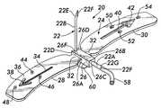
- FIG. 1is an isometric view of one embodiment of a safety angled indwelling needle device with its protective shield in the open condition ready for use;
- FIG. 2is an end view of the device of FIG. 1 showing the protective shield in its closed condition to protect persons from coming into contact with the sharp tip of the needle, and showing by means of phantom lines the shield in the open condition of FIG. 1;
- FIG. 3is a sectional view taken along line 3 — 3 of FIG. 2;
- FIG. 4is an enlarged sectional view taken along line 4 — 4 of FIG. 3 .
- FIG. 1there is shown at 20 one exemplary embodiment of a safety indwelling needle device constructed in accordance with this invention.
- the device 20 shown in FIG. 1comprises the preassembled combination a conventional angled indwelling, e.g., Hubertype, needle 22 and a protective shield 24 for the needle.
- the subject inventionalso contemplates use of a separate shield 24 for selective mounting on any conventional angled indwelling needle to result in an assembly constructed similarly to the device 20 .
- the exemplary needle 22is a conventional Hubertype device. Thus, all the details of its construction will not be reiterated herein in the interests of brevity. Suffice it to state that the needle 22 is a hollow tubular member, e.g., a stainless steel tube, having a linear proximal end portion 22 A and a linear distal end portion 22 B terminating in an angularly extending free end 22 C.
- the distal end portion 22 Aextends generally perpendicularly to the proximal end portion 22 B at point 22 D.
- the free end 22 Cis also somewhat linear, but extends at an acute angle to the axis of the distal end portion 22 B and includes a sharpened tip 22 E in the form of a beveled end free end (FIGS. 1 and 3 ).
- the needle 22includes a central passageway 22 F (FIGS. 1 and 3) extending its entire length from the open beveled free end or tip 22 E to the proximal end 22 G of the proximal end portion
- the needle 22is merely exemplary of various types of angled, indwelling needles that can be used with the subject invention.
- the needleneed not be a Huber type, e.g., one whose distal end is offset or angled, but can be one whose distal end portion is linear or curved or a combination thereof.
- the shieldbasically comprises an integral unit, e.g., a molded biocompatible plastic member, having central hub 26 from which a pair of generally planar wings 28 and 30 project outward.
- the hub 26is an elongated member of generally rectangular cross section having a pair of sidewalls 26 A and 26 B, a top wall 26 C and a bottom wall 26 D.
- the wing 28projects outward from the sidewall 26 A and is a planar member which normally lies in a plane parallel to the top and bottom walls, 26 C and 26 D, respectively of the hub 28 .
- the wing 30projects outward from the sidewall 26 B and is a planar member which normally lies in a plane parallel to the top and bottom walls, 26 C and 26 D, respectively of the hub 26 .
- the needle 22is fixedly secured with respect to the shield 24 .
- the hub 26includes a central passageway 26 E extending therethrough.
- the proximal end portion 22 A of the needle 22is located and held within that passageway, as will be described later.
- a notch 26 Fis located at the end of the hub in the bottom wall 26 D to receive and hold the right angle oriented distal end portion 22 B of the needle 22 so that it is perpendicular to the plane of the wings 28 and 30 when those wings are in their opened, coplanar orientation shown in FIG. 1 .
- the wings 28 and 30are arranged to be flexed or pivoted from their open and coplanar orientation shown in FIG. 1 and by the phantom lines in FIG. 2, to the closed orientation shown in FIG. 2 .
- the direction of flexure of the wingsis shown by the phantom line arrows in FIG. 2 .
- the wingsIn the closed position, the wings abut each other at their distal end portions in a plane generally perpendicular to the plane in which they were disposed in their open orientation, and with the distal end portion 22 B of the needle 22 disposed therebetween to protect users of the device 20 from an accidental needle-stick.
- the portions 32 of the wings 28 and 30 contiguous with the hub 26are of a reduced width and thickness to create a living hinge.
- the plastic forming the wingsis preferably somewhat flexible, thereby enabling the wings to flex or bend readily at their hinges 32 .
- each wingincludes a recess or slot therein which are arranged to conjoin to form a channel in which the distal end portion 22 B of the needle is located when the device 20 is in its closed state.
- the wing 28includes a slot 34 extending down the a portion of the inner surface 36 of the wing 28 aligned with the point 22 D at which the distal end portion 22 B projects perpendicularly to the proximal end portion 22 A of the needle 22 .
- the slot 34extends from approximately the middle of the length of the wing to a point adjacent the wings free end.
- the distal end of the slot 34terminates in an upstanding generally arrowhead shaped wall 38 projecting slightly upward from the inner surface 36 of the wing 28 .
- the wing 30includes a slot 40 extending down the a portion of the inner surface 36 of the wing 30 aligned with the point 22 D at which the distal end portion 22 B projects perpendicularly to the proximal end portion 22 A of the needle 22 .
- the slot 40also ends from approximately the middle of the length of the wing to a point adjacent the wings free end.
- the distal end of the slot 40terminates in a generally arrowhead shaped recess 42 .
- the function of the arrowhead shaped recess 42will also be described later.
- the device 20includes plural releasably securable connectors.
- wing 28includes a plurality, e.g., three, short cylindrical posts 44 , 46 and 48 projecting upward from the inner surface 36 of the wing 28 .
- the posts 44 and 46are aligned on opposite sides of the slot 34 at approximately the middle of the slot.
- the post 48is located adjacent the apex of the arrowhead shaped projecting wall 38 and is axially aligned with the slot 34 .
- the wing 30includes a plurality, e.g., three, circular holes or apertures 50 , 52 and 54 extending inward into the wing from the inner surface 36 of the wing.
- each of the apertures 50 , 52 and 54is just slightly less than the outside diameter of the posts 44 , 46 , and 48 , respectively, to releasably receive the posts therein and to hold them in place therein against accidental disconnection.
- the holes 50 and 52are aligned on opposite sides of the slot 40 at approximately the middle of the slot so that the are axially aligned with the posts 44 and 46 when the wings are in their closed orientation.
- the post 54is located adjacent the apex of the arrowhead shaped recess 42 and is axially aligned with the slot 40 .
- the hole 54is also axially aligned with the posts 48 when the wings are in their closed orientation.
- each of the holesincludes a flared entryway or mouth 56 (FIG. 3 ).
- a length conventional flexible tubing 58is mounted on the proximal end portion 22 A of the needle 22 .
- This tubingis arranged to carry the liquid which is to be introduced by the needle.
- the inside diameter of the passageway 26 E of the hub 26is approximately the same as the outside diameter of the tubing 58 to 4 E receive it and hold it in place, thereby holding the proximal end portion 22 A of the needle within that passageway.
- the notch 26 Fserves to prevent the needle from twisting about the longitudinal axis of the passageway, thereby holding the distal end portion of the needle perpendicular to the plane of the wings when the wings are in their opened orientation.
- the devicecan be applied to the user by securing the wings to the skin of the user at the situs of the needle entry point, whereupon the distally located portion of the needle will project through the skin of the patient, e.g., into the implanted port.
- a short flange 60is provided upstanding from the top wall 26 C of the central hub 26 to serve as a portion that can be grasped between the user's fingers to hold the device 20 and facilitate its mounting and dismounting with respect to the patient.
Landscapes
- Health & Medical Sciences (AREA)
- Vascular Medicine (AREA)
- Engineering & Computer Science (AREA)
- Anesthesiology (AREA)
- Biomedical Technology (AREA)
- Heart & Thoracic Surgery (AREA)
- Hematology (AREA)
- Life Sciences & Earth Sciences (AREA)
- Animal Behavior & Ethology (AREA)
- General Health & Medical Sciences (AREA)
- Public Health (AREA)
- Veterinary Medicine (AREA)
- Infusion, Injection, And Reservoir Apparatuses (AREA)
Abstract
Description
This invention relates generally to hypodermic needles, and more particularly to safety indwelling angled needles, e.g., right angle Huber needles, and protective shields for such needles, to prevent accidental sticking when inserting or removing angled needles from the body of a living being.
As is known implanted ports for the delivery of drugs or other liquid materials are commonly utilized in the medical field today. Such ports are typically placed in a subcutaneous pocket, e.g., the anterior upper chest wall below the clavicle, and typically include a chamber for the drug or other liquid and a pierceable, e.g., rubber, septum for receipt of a needle to either fill or empty the chamber. Special non-coring needles (sometimes referred to as “Huber” needles) are commonly used with such ports to minimize the damage to the septum resulting from repeated piercing by the needle. Such damage may lead to infusion of the septum fragment(s) into the patient's vascular system or into any catheter or other device having access to the port, thereby occluding the port. In U.S. Pat. No. 2,748,759 (Huber) there is shown a Huber type safety needle.
As is known, Huber needles may be straight or angled and may be of various lengths depending upon the application, e.g., drawing blood, filling the chamber, flushing chamber, etc. In order to hold the needle in place in the port Huber needles frequently include a pair of flanges which are arranged to be secured, e.g., taped, to the patient's skin at the location of the port.
As will be recognized by those skilled in the art removal of a Huber needle from a port, particularly, a right angle shaped Huber needle, frequently results in an accidental piercing or “needle-stick” of the person removing the needle.
U.S. Pat. No. 5,505,711 (Arakawa et al.) discloses an indwelling injector needle device constructed to reduce the risk of accidental needle-sticks. The device includes a pair of wings and a cannula or needle body, a hub supporting a proximal end of the needle body, a tube in fluid communication with the needle body, a cylindrical holder having a distal end from which the wings protrude, and a latching mechanism. The hub can slide along an inner periphery of the holder between a first position near the distal end of the holder and a second position near a proximal end of the holder. A latching mechanism is formed in and disposed between the hub and the holder so that the hub is inhibited from moving from the first position toward the second position, and vice versa. The needle edge can be retracted within the holder while its wings remain fixed to a patient's skin.
U.S. Pat. No. 5,879,330 (Bell) discloses a needle retraction device for removing a needle, such as a right angled “Huber” needle, from a patient without danger of an accidental needle-stick. The device basically comprises an exterior housing having an interior compartment and a slidable member. The housing has an exterior wall which defines an interior compartment. The slidable member has a pair of spaced apart movable legs separated from one another by an elongate slot and is located within the interior compartment. The pair of spaced apart movable legs are also spaced from a remainder of the slidable member by a cavity or area which is sized to receive the needle. The slidable member is movable from a first position, in which the pair of spaced apart movable legs are located outside of the interior compartment of the needle retraction device for receiving a needle, and a second retracted position, in which the pair of spaced apart movable legs along with a supported needle, are completely retracted inside the interior compartment of the housing to prevent an inadvertent needle stick.
U.S. Pat. No. 5,921,969 (Vallenunga et al.) discloses a device for shielding a butterfly needle, such as a straight or right angled “Huber” needle, to protect the user against accidental needle-stick injuries. The device basically comprises a hollow box-like member having a pair of engaging complementary shield sections which are adapted to be secured together to form a cavity for receipt of the needle therein.
U.S. Pat. No. 5,951,522 (Rosato et al.) also discloses a device whose intent is to reduce accidental needle-sticks caused by right angled Huber type needles. To that end the device of this patent is in the form of hypodermic needle safety enclosure for a right angle shaped hypodermic needle. A wing assembly is mounted on the hypodermic needle. The wing assembly may be either a single integral member having a plurality of spaced apart fold lines which permits the integral member to be folded between a mounting position and a protective position or a pair of wing members which are mounted in a scissors arrangement which is movable between a mounting position and a protective position. Upon withdrawing of the needle from the installed position within the body of a human, the wing assembly is automatically positioned to encase the sharpened point of the needle, thereby preventing undesired injury by the needle to the medical practitioner that is installing and removing of the enclosure.
While the devices of the aforementioned patents appear suitable for their intended purposes, the still leave much to be desired from various standpoints, such as simplicity of construction, intuitiveness of operation and ease of use.
A safety angled indwelling needle device and a protective shield for a safety angled indwelling needle. The safety device comprises the combination of an angled indwelling, e.g., Huber type, needle and a protective shield. The protective shield can be a separate unit for use with an angled Huber needle.
The needle is a hollow member having a distal end portion and a proximal end portion, with the distal end portion extending at an angle to the proximal end portion and terminates in a piercing tip.
The protective shield comprises a central hub and a pair of wing members, e.g., an integrally molded unit. The central hub has a longitudinal central axis, a distal end, a proximal end and a passageway extending through the central hub along the horizontal axis. The proximal end portion of the needle extends through said passageway, e.g., is connected to a tube thereat. The distal end portion of the needle extends out of the passageway in the central hub and extends at an angle, e.g., approximately perpendicularly, to the passageway.
Each of the wing members of the protective shield are generally planar. Each wing member is mounted to the central hub, e.g., secured by a living hinge, on opposite sides of the central hub and is arranged to be moved, e.g., flexed, from an open state, wherein the wing members are generally coplanar with each other, to a closed state, wherein the wing members abut each other with the distal portion of the needle disposed between them, to enclose the needle's piercing tip. Each of the wing members also includes at least one connector, e.g., respective projections and apertures, for holding the wing members in the closed state.
In accordance with one exemplary, but not exclusive embodiment, of this invention each wing member includes include a linear channel therein. The channels conjoin when the wing members are in their closed state to form an enclosed recess for receipt of the needle's piercing tip. Each channel is generally linear and extends within its associated wing member from a first end point adjacent the central hub to a second end point more remote from the hub. The use of the linear channels while not mandatory, desirable, to further ensure that persons contacting the device will not be pierced by the enclosed needle.
In accordance with the aforementioned exemplary embodiment, one of the channels of one of the wing members includes an arrowhead-shaped recess located at the second end point of that wing member. The other of the channels includes an arrowhead shaped projection located at the second end point of the other of the wing member. The arrowhead shaped recess and the arrowhead shaped projection point away from the central hub to provide a visual indication of the direction that the wing members should be flexed when they are in the open state to move them to the closed state. When the wing members are in the closed state the arrowhead shaped projection mates with the arrowhead shaped recess so as not to interfere with the formation of the enclosed recess for the piercing tip when the two wing members are in their closed state.
FIG. 1 is an isometric view of one embodiment of a safety angled indwelling needle device with its protective shield in the open condition ready for use;
FIG. 2 is an end view of the device of FIG. 1 showing the protective shield in its closed condition to protect persons from coming into contact with the sharp tip of the needle, and showing by means of phantom lines the shield in the open condition of FIG. 1;
FIG. 3 is a sectional view taken alongline 3—3 of FIG. 2; and
FIG. 4 is an enlarged sectional view taken alongline 4—4 of FIG.3.
Referring to FIG. 1, there is shown at20 one exemplary embodiment of a safety indwelling needle device constructed in accordance with this invention. It should be pointed out at this juncture that thedevice 20 shown in FIG. 1 comprises the preassembled combination a conventional angled indwelling, e.g., Hubertype,needle 22 and aprotective shield 24 for the needle. The subject invention also contemplates use of aseparate shield 24 for selective mounting on any conventional angled indwelling needle to result in an assembly constructed similarly to thedevice 20.
Theexemplary needle 22 is a conventional Hubertype device. Thus, all the details of its construction will not be reiterated herein in the interests of brevity. Suffice it to state that theneedle 22 is a hollow tubular member, e.g., a stainless steel tube, having a linearproximal end portion 22A and a lineardistal end portion 22B terminating in an angularly extendingfree end 22C. Thedistal end portion 22A extends generally perpendicularly to theproximal end portion 22B atpoint 22D. Thefree end 22C is also somewhat linear, but extends at an acute angle to the axis of thedistal end portion 22B and includes a sharpenedtip 22E in the form of a beveled end free end (FIGS.1 and3). Theneedle 22 includes acentral passageway 22F (FIGS. 1 and 3) extending its entire length from the open beveled free end ortip 22E to theproximal end 22G of theproximal end portion 22B.
It should be pointed out at this juncture that theneedle 22 is merely exemplary of various types of angled, indwelling needles that can be used with the subject invention. Thus, the needle need not be a Huber type, e.g., one whose distal end is offset or angled, but can be one whose distal end portion is linear or curved or a combination thereof.
The shield basically comprises an integral unit, e.g., a molded biocompatible plastic member, havingcentral hub 26 from which a pair of generallyplanar wings hub 26 is an elongated member of generally rectangular cross section having a pair ofsidewalls top wall 26C and abottom wall 26D. Thewing 28 projects outward from thesidewall 26A and is a planar member which normally lies in a plane parallel to the top and bottom walls,26C and26D, respectively of thehub 28. In a similar manner thewing 30 projects outward from thesidewall 26B and is a planar member which normally lies in a plane parallel to the top and bottom walls,26C and26D, respectively of thehub 26.
Theneedle 22 is fixedly secured with respect to theshield 24. To that end thehub 26 includes acentral passageway 26E extending therethrough. Theproximal end portion 22A of theneedle 22 is located and held within that passageway, as will be described later. Anotch 26F is located at the end of the hub in thebottom wall 26D to receive and hold the right angle orienteddistal end portion 22B of theneedle 22 so that it is perpendicular to the plane of thewings
Thewings
In the closed position, the wings abut each other at their distal end portions in a plane generally perpendicular to the plane in which they were disposed in their open orientation, and with thedistal end portion 22B of theneedle 22 disposed therebetween to protect users of thedevice 20 from an accidental needle-stick.
In order to facilitate the flexing or pivoting of the wings from their open position to their closed position theportions 32 of thewings hub 26 are of a reduced width and thickness to create a living hinge. Moreover, the plastic forming the wings is preferably somewhat flexible, thereby enabling the wings to flex or bend readily at theirhinges 32.
As best seen in FIGS. 1-3 each wing includes a recess or slot therein which are arranged to conjoin to form a channel in which thedistal end portion 22B of the needle is located when thedevice 20 is in its closed state. In particular, thewing 28 includes aslot 34 extending down the a portion of theinner surface 36 of thewing 28 aligned with thepoint 22D at which thedistal end portion 22B projects perpendicularly to theproximal end portion 22A of theneedle 22. Theslot 34 extends from approximately the middle of the length of the wing to a point adjacent the wings free end. The distal end of theslot 34 terminates in an upstanding generally arrowhead shapedwall 38 projecting slightly upward from theinner surface 36 of thewing 28. The function of the projection orwall 38 will be described later. In a similar manner thewing 30 includes aslot 40 extending down the a portion of theinner surface 36 of thewing 30 aligned with thepoint 22D at which thedistal end portion 22B projects perpendicularly to theproximal end portion 22A of theneedle 22. Theslot 40 also ends from approximately the middle of the length of the wing to a point adjacent the wings free end. The distal end of theslot 40 terminates in a generally arrowhead shapedrecess 42. The function of the arrowhead shapedrecess 42 will also be described later.
As can be seen in FIG. 2 when the twowings slots free end 22F and contiguous portion of thedistal end portion 22B of the needle is located and confined. This action effectively prevents anyone in contact with thedevice 20 from accidentally receiving a needle-stick from the needle. In order to hold the wings in their closed orientation against the natural bias of the material forming the wings which tends to try and return them to their opened orientation, thedevice 20 includes plural releasably securable connectors. In particular, in the case of the illustrated exemplary embodiment,wing 28 includes a plurality, e.g., three, shortcylindrical posts inner surface 36 of thewing 28. Theposts slot 34 at approximately the middle of the slot. Thepost 48 is located adjacent the apex of the arrowhead shaped projectingwall 38 and is axially aligned with theslot 34. Thewing 30 includes a plurality, e.g., three, circular holes orapertures inner surface 36 of the wing. The inside diameter of each of theapertures posts holes slot 40 at approximately the middle of the slot so that the are axially aligned with theposts post 54 is located adjacent the apex of the arrowhead shapedrecess 42 and is axially aligned with theslot 40. Thehole 54 is also axially aligned with theposts 48 when the wings are in their closed orientation. In order to facilitate the entry of theposts holes
As best seen in FIGS. 1 and 3 a length conventionalflexible tubing 58 is mounted on theproximal end portion 22A of theneedle 22. This tubing is arranged to carry the liquid which is to be introduced by the needle. The inside diameter of thepassageway 26E of thehub 26 is approximately the same as the outside diameter of thetubing 58 to4E receive it and hold it in place, thereby holding theproximal end portion 22A of the needle within that passageway. Thenotch 26F serves to prevent the needle from twisting about the longitudinal axis of the passageway, thereby holding the distal end portion of the needle perpendicular to the plane of the wings when the wings are in their opened orientation. Thus, the device can be applied to the user by securing the wings to the skin of the user at the situs of the needle entry point, whereupon the distally located portion of the needle will project through the skin of the patient, e.g., into the implanted port.
As best seen in FIGS. 1 and 3 ashort flange 60 is provided upstanding from thetop wall 26C of thecentral hub 26 to serve as a portion that can be grasped between the user's fingers to hold thedevice 20 and facilitate its mounting and dismounting with respect to the patient.
Without further elaboration the foregoing will so fully illustrate my invention that others may, by applying current or future knowledge, adopt the same for use under various conditions of service.
Claims (23)
1. A safety Huber angled needle device, said device comprising a Huber needle and a protective shield, said Huber needle comprising a hollow member having a distal end portion and a proximal end portion, said distal end portion extending at an angle to said proximal end portion and terminating in a piercing tip, said protective shield comprising a central hub and a pair of first and second wing members, said central hub having diametrically opposed sides, a longitudinal central axis, a distal end, a proximal end and a passageway extending through said central hub along said longitudinal central axis, said proximal end portion of said Huber needle extending through said passageway so that said distal end portion of said Huber needle extends out of said passageway and at an angle to said longitudinal central axis, said first and second wing members each being a generally planar member having an inner surface, a free end and a fixed end, said fixed end of said first wing member being connected to said central hub at one of said sides, said fixed end of said second wing member being connected to said central hub at the other of said sides, whereupon said first and second wing members are connected to said central hub diametrically opposed from each other, each of said first and second wing members being arranged to be moved from an open state, wherein said first and second wing members are generally coplanar with each other, to a closed state, wherein said inner surfaces of said first and second wing members contiguous with their free ends abut each other with said distal portion of said Huber needle disposed between said inner surfaces of said first and second wing members to enclose said piercing tip, said inner surface of each of said first and second wing members including at least one connector, said at least one connector of said first wing member being arranged for engagement with said at least one connector of said second wing member for holding said first and second wing members in said closed state.
2. The device ofclaim 1 wherein at least one of said wing members includes a channel therein for receipt of said piercing tip when said wing members are in said closed state.
3. The device ofclaim 2 wherein both of said wing members include a channel therein, said channels conjoining when said wing members are in said closed state to form an enclosed recess for receipt of said piercing tip.
4. The device ofclaim 3 wherein each channel is generally linear and extends within its associated wing member from a first end point adjacent said central hub to a second end point more remote from said central hub, and wherein one of said channels of one of said wing members includes an arrowhead-shaped recess located at said second end point of said one of said wing members and wherein the other of said channels includes an arrowhead shaped projection located at said second end point of the other of said wing members, said arrowhead shaped projection being arranged to fit within said arrowhead shaped recess when said wing members are in said closed state.
5. The device ofclaim 1 wherein said at least one connector comprise at least one projection and at least one cooperating bore.
6. The device ofclaim 5 wherein one of said wing portions includes said at least one projection and wherein the other of said wing members includes said at least one bore.
7. The device ofclaim 6 wherein said at least one projection comprises post and wherein said at least one bore comprises an aperture whose cross sectional area is approximately equal to that of said post to tightly receive said post therein.
8. The device ofclaim 7 wherein said aperture includes a flared mouth for facilitating entry of said post into said aperture.
9. The device ofclaim 8 wherein said device comprises plural apertures and plural cooperating posts.
10. The device ofclaim 1 wherein said wing members are flexible to bend from said open state to said closed state.
11. The device ofclaim 1 wherein said shield is formed of a moldable material and wherein said wing members are connected to said central hub on opposite sides thereof by respective living hinges.
12. The device ofclaim 11 wherein said wings are flexible.
13. The device ofclaim 1 additionally comprising a flange upstanding from said central hub, said flange extending in the opposite directions than said wing members when said wing members are in said closed state.
14. The device ofclaim 13 wherein said central hub is of a generally rectangular cross sectional area.
15. The device ofclaim 1 additionally comprising a tube connected to said proximal end portion of said Huber needle.
16. A protective shield for a Huber angled needle, said Huber needle comprising a hollow member having a distal end portion and a proximal end portion, the distal end portion extending at an angle to the proximal end portion and terminating in a piercing tip, said protective shield comprising a central hub and a pair of wing members, said central hub having diametrically opposed sides, a longitudinal central axis, a distal end, a proximal end and a passageway extending through said central hub along said longitudinal central axis, said passageway being adapted to receive the proximal end portion of the Huber needle extending through it so that the distal end portion of the Huber needle extends out of said passageway and at an angle to said longitudinal central axis, each of said wing members being a generally planar member having an inner surface, a free end and a fixed end, said fixed end of said first wing member being connected to said central hub at one of said sides, said fixed end of said second wing member being connected to said central hub at the other of said sides, whereupon said first and second wing members are connected to said central hub diametrically opposed from each other, each of said first and second wing members being arranged to be moved from an open state, wherein said first and second wing members are generally coplanar with each other, to a closed state, wherein said inner surfaces of said first and second wing members abut each other with the distal portion of the Huber needle disposed between said inner surfaces of said first and second wing members to enclose the piercing tip of the Huber needle, said inner surface of each of said first and second wing members including at least one connector, said at least one connector of said first wing member being arranged for engagement with said at least one connector of said second wing member for holding said first and second wing members in said closed state.
17. The shield ofclaim 16 wherein at least one of said wing members includes a channel therein for receipt of the piercing tip of the Huber needle when said wing members are in said closed state.
18. The shield ofclaim 17 wherein both of said wing members include a channel therein, said channels conjoining when said wing members are in said closed state to form an enclosed recess for receipt of the piercing tip of the Huber needle.
19. The shield ofclaim 16 wherein said at least one connector comprise at least one projection and at least one cooperating bore.
20. The shield ofclaim 19 wherein one of said wing portions includes said at least one projection and wherein the other of said wing members includes said at least one bore.
21. The shield ofclaim 16 wherein said wing members are flexible to bend from said open state to said closed state.
22. The shield ofclaim 16 wherein said shield is formed of a moldable material and wherein said wing members are connected to said central hub on opposite sides thereof by respective living hinges.
23. The shield ofclaim 12 wherein said wings are flexible.
Priority Applications (1)
| Application Number | Priority Date | Filing Date | Title |
|---|---|---|---|
| US09/782,335US6500155B2 (en) | 2001-02-13 | 2001-02-13 | Safety angled indwelling needle and a protective shield for a safety angled indwelling needle |
Applications Claiming Priority (1)
| Application Number | Priority Date | Filing Date | Title |
|---|---|---|---|
| US09/782,335US6500155B2 (en) | 2001-02-13 | 2001-02-13 | Safety angled indwelling needle and a protective shield for a safety angled indwelling needle |
Publications (2)
| Publication Number | Publication Date |
|---|---|
| US20020111581A1 US20020111581A1 (en) | 2002-08-15 |
| US6500155B2true US6500155B2 (en) | 2002-12-31 |
Family
ID=25125720
Family Applications (1)
| Application Number | Title | Priority Date | Filing Date |
|---|---|---|---|
| US09/782,335Expired - Fee RelatedUS6500155B2 (en) | 2001-02-13 | 2001-02-13 | Safety angled indwelling needle and a protective shield for a safety angled indwelling needle |
Country Status (1)
| Country | Link |
|---|---|
| US (1) | US6500155B2 (en) |
Cited By (95)
| Publication number | Priority date | Publication date | Assignee | Title |
|---|---|---|---|---|
| US20030114797A1 (en)* | 2001-12-17 | 2003-06-19 | Vaillancourt Vincent L. | Safety needle with collapsible sheath |
| US6676633B2 (en)* | 2001-10-24 | 2004-01-13 | Horizon Medical Products, Inc. | Intravascular administration set needle safety device |
| US6736800B2 (en)* | 2001-12-04 | 2004-05-18 | Disetronic Services, Ag | Cannula support having a needle covering function and packaging structure comprising a cannula support |
| US6755805B1 (en)* | 2002-09-13 | 2004-06-29 | Alan Reid | Needle device having enhanced safety |
| US20040138613A1 (en)* | 2002-09-13 | 2004-07-15 | Alan Reid | Needle device having slideable member providing enhanced safety |
| WO2005025637A2 (en) | 2003-09-17 | 2005-03-24 | Dali Medical Devices Ltd. | Automatic needle device |
| US20050080386A1 (en)* | 2002-09-13 | 2005-04-14 | Alan Reid | Needle device having retractable needle providing enhanced safety |
| US20050251098A1 (en)* | 2002-11-21 | 2005-11-10 | Martin Wyss | Insertion aid for inserting a cannula of a catheter head into organic tissue |
| US6969372B1 (en)* | 2003-01-07 | 2005-11-29 | Halseth Thor R | Automatic retraction Huber needle safety enclosure |
| US20060155318A1 (en)* | 2002-07-25 | 2006-07-13 | Toru Shinzato | Hole-forming pin for inserting indwelling needle and jig for installing the pin |
| US20060253076A1 (en)* | 2005-04-27 | 2006-11-09 | C.R. Bard, Inc. | Infusion apparatuses and methods of use |
| US20080177234A1 (en)* | 2006-11-21 | 2008-07-24 | Candace Keaton | Safety subcutaneous infusion set |
| US7425208B1 (en) | 2003-08-29 | 2008-09-16 | Vitello Jonathan J | Needle assembly facilitating complete removal or nearly complete removal of a composition from a container |
| US20080262434A1 (en)* | 2007-04-20 | 2008-10-23 | Vaillancourt Michael J | Huber needle with safety sheath |
| US20080281264A1 (en)* | 2007-05-08 | 2008-11-13 | Alan Reid | Methods and apparatus for syringe adapter |
| EP2119462A1 (en) | 2008-05-15 | 2009-11-18 | Süddeutsche Feinmechanik GmbH | Cannula assembly |
| US20090299302A1 (en)* | 2008-06-02 | 2009-12-03 | Paul Lambert | Devices and methods for protecting a user from a sharp tip of a medical needle |
| US20100152677A1 (en)* | 2008-12-11 | 2010-06-17 | Vaillancourt Michael J | Device for removing a huber needle from a patient |
| US7776016B1 (en)* | 2004-02-26 | 2010-08-17 | C. R. Bard, Inc. | Huber needle safety enclosure |
| US7785302B2 (en) | 2005-03-04 | 2010-08-31 | C. R. Bard, Inc. | Access port identification systems and methods |
| US7947022B2 (en) | 2005-03-04 | 2011-05-24 | C. R. Bard, Inc. | Access port identification systems and methods |
| US7985216B2 (en) | 2004-03-16 | 2011-07-26 | Dali Medical Devices Ltd. | Medicinal container engagement and automatic needle device |
| DE202010000443U1 (en) | 2010-03-23 | 2011-08-08 | Süddeutsche Feinmechanik GmbH | The cannula assembly |
| US8021324B2 (en) | 2007-07-19 | 2011-09-20 | Medical Components, Inc. | Venous access port assembly with X-ray discernable indicia |
| US8025639B2 (en) | 2005-04-27 | 2011-09-27 | C. R. Bard, Inc. | Methods of power injecting a fluid through an access port |
| US8029482B2 (en) | 2005-03-04 | 2011-10-04 | C. R. Bard, Inc. | Systems and methods for radiographically identifying an access port |
| US20120041253A1 (en)* | 2010-08-10 | 2012-02-16 | Ching-Yang Wu | Protective Apparatus for Chemotherapy Injection Needle |
| US20120065587A1 (en)* | 2010-09-10 | 2012-03-15 | C. R. Bard, Inc. | Systems for isolation of a needle-based infusion set |
| US8177762B2 (en) | 1998-12-07 | 2012-05-15 | C. R. Bard, Inc. | Septum including at least one identifiable feature, access ports including same, and related methods |
| US8202259B2 (en) | 2005-03-04 | 2012-06-19 | C. R. Bard, Inc. | Systems and methods for identifying an access port |
| US8257325B2 (en) | 2007-06-20 | 2012-09-04 | Medical Components, Inc. | Venous access port with molded and/or radiopaque indicia |
| US8323251B2 (en) | 2008-01-14 | 2012-12-04 | Fenwal, Inc. | Phlebotomy needle assembly and frangible cover |
| US8376998B2 (en) | 2003-09-17 | 2013-02-19 | Elcam Medical Agricultural Cooperative Association Ltd. | Automatic injection device |
| USD676955S1 (en) | 2010-12-30 | 2013-02-26 | C. R. Bard, Inc. | Implantable access port |
| US8439870B2 (en) | 2008-09-10 | 2013-05-14 | B. Braun Medical Inc. | Safety needle assembly and methods |
| USD682416S1 (en) | 2010-12-30 | 2013-05-14 | C. R. Bard, Inc. | Implantable access port |
| US8715244B2 (en) | 2009-07-07 | 2014-05-06 | C. R. Bard, Inc. | Extensible internal bolster for a medical device |
| US8932271B2 (en) | 2008-11-13 | 2015-01-13 | C. R. Bard, Inc. | Implantable medical devices including septum-based indicators |
| US20150073382A1 (en)* | 2013-09-12 | 2015-03-12 | Michael J. Botich | Rotatable hypodermic needle and method of use |
| US20150151054A1 (en)* | 2013-12-03 | 2015-06-04 | Becton, Dickinson And Company | Blood Collection Device with Double Pivot Shields |
| US9079004B2 (en) | 2009-11-17 | 2015-07-14 | C. R. Bard, Inc. | Overmolded access port including anchoring and identification features |
| US9125985B2 (en) | 2013-04-01 | 2015-09-08 | iMed Technology, Inc. | Needle with protective cover member |
| US9265912B2 (en) | 2006-11-08 | 2016-02-23 | C. R. Bard, Inc. | Indicia informative of characteristics of insertable medical devices |
| US9308322B2 (en) | 2008-06-02 | 2016-04-12 | Emed Technologies Corporation | Devices and methods for protecting a user from a sharp tip of a medical needle |
| US9311592B1 (en) | 2012-08-31 | 2016-04-12 | Medical Device Engineering, LLC. | Support and closure assembly for discharge port of a syringe and tracking system therefore |
| US9402967B1 (en) | 2010-05-27 | 2016-08-02 | Medical Device Engineering, Llc | Tamper evident cap assembly |
| US9463310B1 (en) | 2010-12-03 | 2016-10-11 | Medical Device Engineering, LLC. | Tamper indicating closure assembly |
| US9474888B2 (en) | 2005-03-04 | 2016-10-25 | C. R. Bard, Inc. | Implantable access port including a sandwiched radiopaque insert |
| US9579496B2 (en) | 2007-11-07 | 2017-02-28 | C. R. Bard, Inc. | Radiopaque and septum-based indicators for a multi-lumen implantable port |
| US9579451B2 (en) | 2007-08-09 | 2017-02-28 | Uwe Stumpp | Device for administering a cannula |
| US9610432B2 (en) | 2007-07-19 | 2017-04-04 | Innovative Medical Devices, Llc | Venous access port assembly with X-ray discernable indicia |
| US9642986B2 (en) | 2006-11-08 | 2017-05-09 | C. R. Bard, Inc. | Resource information key for an insertable medical device |
| US20170165419A1 (en)* | 2014-03-28 | 2017-06-15 | Baxalta Incorporated | Subcutaneous infusion device for injecting medicinal substances |
| US9821152B1 (en) | 2013-03-04 | 2017-11-21 | Medical Device Engineering, LLC. | Closure assembly |
| US9855191B1 (en) | 2013-12-09 | 2018-01-02 | Jonathan J. Vitello | Tamper evident shield assembly with tracking |
| US10166343B1 (en) | 2015-03-13 | 2019-01-01 | Timothy Brandon Hunt | Noise evident tamper cap |
| US10166347B1 (en) | 2014-07-18 | 2019-01-01 | Patrick Vitello | Closure assembly for a medical device |
| US10207099B1 (en) | 2014-02-21 | 2019-02-19 | Patrick Vitello | Closure assembly for medical fitting |
| US10300263B1 (en) | 2015-02-27 | 2019-05-28 | Timothy Brandon Hunt | Closure assembly for a medical connector |
| US10307581B2 (en) | 2005-04-27 | 2019-06-04 | C. R. Bard, Inc. | Reinforced septum for an implantable medical device |
| US10307548B1 (en) | 2016-12-14 | 2019-06-04 | Timothy Brandon Hunt | Tracking system and method for medical devices |
| US10315024B1 (en) | 2015-03-19 | 2019-06-11 | Patick Vitello | Torque limiting closure assembly |
| US20190316690A1 (en)* | 2016-11-08 | 2019-10-17 | Mueller International, Llc | Valve body with identification tab |
| US10525234B2 (en) | 2010-09-10 | 2020-01-07 | C. R. Bard, Inc. | Antimicrobial/haemostatic interface pad for placement between percutaneously placed medical device and patient skin |
| USD884160S1 (en) | 2019-02-25 | 2020-05-12 | iMed Technology, Inc. | Huber safety needle |
| US10729846B2 (en) | 2010-09-10 | 2020-08-04 | C. R. Bard, Inc. | Self-sealing pad for a needle-based infusion set |
| US10758684B1 (en) | 2017-03-03 | 2020-09-01 | Jonathan J. Vitello | Tamper evident assembly |
| USD903865S1 (en) | 2018-11-19 | 2020-12-01 | International Medical Industries, Inc. | Self-righting tip cap |
| US10888672B1 (en) | 2017-04-06 | 2021-01-12 | International Medical Industries, Inc. | Tamper evident closure assembly for a medical device |
| US10898659B1 (en) | 2017-05-19 | 2021-01-26 | International Medical Industries Inc. | System for handling and dispensing a plurality of products |
| US10912898B1 (en) | 2014-02-03 | 2021-02-09 | Medical Device Engineering Llc | Tamper evident cap for medical fitting |
| US10933202B1 (en) | 2017-05-19 | 2021-03-02 | International Medical Industries Inc. | Indicator member of low strength resistance for a tamper evident closure |
| US10953162B1 (en) | 2016-12-28 | 2021-03-23 | Timothy Brandon Hunt | Tamper evident closure assembly |
| US11040149B1 (en) | 2017-03-30 | 2021-06-22 | International Medical Industries | Tamper evident closure assembly for a medical device |
| US11097071B1 (en) | 2016-12-14 | 2021-08-24 | International Medical Industries Inc. | Tamper evident assembly |
| US11278681B1 (en) | 2018-02-20 | 2022-03-22 | Robert Banik | Tamper evident adaptor closure |
| USD948713S1 (en) | 2019-09-03 | 2022-04-12 | International Medical Industries, Inc. | Asymmetrical self righting tip cap |
| US11357588B1 (en) | 2019-11-25 | 2022-06-14 | Patrick Vitello | Needle packaging and disposal assembly |
| US11413406B1 (en) | 2018-03-05 | 2022-08-16 | Jonathan J. Vitello | Tamper evident assembly |
| US11426328B1 (en) | 2018-08-31 | 2022-08-30 | Alexander Ollmann | Closure for a medical container |
| US11471610B1 (en) | 2018-10-18 | 2022-10-18 | Robert Banik | Asymmetrical closure for a medical device |
| US11523970B1 (en) | 2020-08-28 | 2022-12-13 | Jonathan Vitello | Tamper evident shield |
| US11541180B1 (en) | 2017-12-21 | 2023-01-03 | Patrick Vitello | Closure assembly having a snap-fit construction |
| US11690994B1 (en) | 2018-07-13 | 2023-07-04 | Robert Banik | Modular medical connector |
| US11697527B1 (en) | 2019-09-11 | 2023-07-11 | Logan Hendren | Tamper evident closure assembly |
| US11779520B1 (en) | 2018-07-02 | 2023-10-10 | Patrick Vitello | Closure for a medical dispenser including a one-piece tip cap |
| US11793987B1 (en) | 2018-07-02 | 2023-10-24 | Patrick Vitello | Flex tec closure assembly for a medical dispenser |
| US11857751B1 (en) | 2018-07-02 | 2024-01-02 | International Medical Industries Inc. | Assembly for a medical connector |
| US11872187B1 (en) | 2020-12-28 | 2024-01-16 | Jonathan Vitello | Tamper evident seal for a vial cover |
| US11890443B2 (en) | 2008-11-13 | 2024-02-06 | C. R. Bard, Inc. | Implantable medical devices including septum-based indicators |
| US11904149B1 (en) | 2020-02-18 | 2024-02-20 | Jonathan Vitello | Oral tamper evident closure with retained indicator |
| US11911339B1 (en) | 2019-08-15 | 2024-02-27 | Peter Lehel | Universal additive port cap |
| US20240252800A1 (en)* | 2014-12-18 | 2024-08-01 | Versago Vascular Access, Inc. | Devices, systems and methods for removal and replacement of a catheter for an implanted access port |
| US12070591B1 (en) | 2020-12-14 | 2024-08-27 | Patrick Vitello | Snap action tamper evident closure assembly |
| US12172803B1 (en) | 2021-10-04 | 2024-12-24 | Patrick Vitello | Tamper evident integrated closure |
Families Citing this family (51)
| Publication number | Priority date | Publication date | Assignee | Title |
|---|---|---|---|---|
| USD526409S1 (en) | 1998-07-14 | 2006-08-08 | Unomedical A/S | Medical puncturing device |
| US6830562B2 (en) | 2001-09-27 | 2004-12-14 | Unomedical A/S | Injector device for placing a subcutaneous infusion set |
| ITTO20011228A1 (en) | 2001-12-28 | 2003-06-28 | Cane Srl | DISPOSABLE NEEDLE CONTAINER. |
| DE60304681T2 (en) | 2002-02-12 | 2007-01-25 | Unomedical A/S | INFUSION DEVICE WITH NADELSCHUTZHÜLSE |
| US20040051019A1 (en) | 2002-09-02 | 2004-03-18 | Mogensen Lasse Wesseltoft | Apparatus for and a method of adjusting the length of an infusion tube |
| AU2003258487A1 (en) | 2002-09-02 | 2004-03-19 | Unomedical A/S | A device for subcutaneous administration of a medicament to a patient |
| EP1534378B1 (en) | 2002-09-02 | 2008-12-31 | Unomedical A/S | A device for subcutaneous administration of a medicament to a patient and tubing for same |
| AU2003257754A1 (en) | 2002-09-02 | 2004-03-19 | Unomedical A/S | An apparatus and a method for adjustment of the length of an infusion tubing |
| DK200201823A (en) | 2002-11-26 | 2004-05-27 | Maersk Medical As | Connection piece for a hose connection |
| US20040158202A1 (en) | 2003-02-12 | 2004-08-12 | Soren Jensen | Cover |
| FR2851921B1 (en)* | 2003-03-05 | 2006-04-07 | Mokhtar Chawki | DEVICE FOR DIRECT VENOUS PUNCTURE |
| US7070580B2 (en) | 2003-04-01 | 2006-07-04 | Unomedical A/S | Infusion device and an adhesive sheet material and a release liner |
| USD576267S1 (en) | 2003-10-15 | 2008-09-02 | Unomedical A/S | Medical infusion device |
| USD579541S1 (en) | 2003-10-15 | 2008-10-28 | Unomedical A/S | Medical insertion device |
| USD554253S1 (en) | 2003-10-15 | 2007-10-30 | Unomedical A/S | Medical infusion device |
| MXPA06010784A (en) | 2004-03-26 | 2006-12-15 | Unomedical As | Injector device for infusion set. |
| US8062250B2 (en) | 2004-08-10 | 2011-11-22 | Unomedical A/S | Cannula device |
| JP4319601B2 (en)* | 2004-08-26 | 2009-08-26 | 川澄化学工業株式会社 | Curved needle with wings |
| US7867199B2 (en) | 2004-12-10 | 2011-01-11 | Unomedical A/S | Inserter |
| US7985199B2 (en) | 2005-03-17 | 2011-07-26 | Unomedical A/S | Gateway system |
| CA2612664A1 (en) | 2005-06-28 | 2007-01-04 | Unomedical A/S | Packing for infusion set and method of applying an infusion set |
| EP1762259B2 (en) | 2005-09-12 | 2025-01-01 | Unomedical A/S | Inserter for an infusion set with a first and second spring units |
| USD655807S1 (en) | 2005-12-09 | 2012-03-13 | Unomedical A/S | Medical device |
| DK1962926T3 (en) | 2005-12-23 | 2009-09-28 | Unomedical As | injection device |
| WO2007098771A2 (en) | 2006-02-28 | 2007-09-07 | Unomedical A/S | Inserter for infusion part and infusion part provided with needle protector |
| CA2653631A1 (en) | 2006-06-07 | 2007-12-13 | Unomedical A/S | Inserter |
| CA2653764A1 (en) | 2006-06-09 | 2007-12-13 | Unomedical A/S | Mounting pad |
| CA2659077A1 (en)* | 2006-08-02 | 2008-02-07 | Unomedical A/S | Insertion device |
| JP2009545341A (en) | 2006-08-02 | 2009-12-24 | ウノメディカル アクティーゼルスカブ | Cannula and delivery device |
| EP1917990A1 (en) | 2006-10-31 | 2008-05-07 | Unomedical A/S | Infusion set |
| EP2155311B1 (en) | 2007-06-20 | 2013-01-02 | Unomedical A/S | A method and an apparatus for making a catheter |
| AU2008270327A1 (en) | 2007-07-03 | 2009-01-08 | Unomedical A/S | Inserter having bistable equilibrium states |
| DE602008005153D1 (en)* | 2007-07-10 | 2011-04-07 | Unomedical As | INSERT WITH TWO SPRINGS |
| AU2008277763B2 (en) | 2007-07-18 | 2011-11-10 | Unomedical A/S | Insertion device with pivoting action |
| ATE522240T1 (en) | 2008-02-13 | 2011-09-15 | Unomedical As | SEAL BETWEEN A CANNULAR PART AND A FLUID PATH |
| US9566384B2 (en) | 2008-02-20 | 2017-02-14 | Unomedical A/S | Insertion device with horizontally moving part |
| AU2009331635A1 (en) | 2008-12-22 | 2011-06-23 | Unomedical A/S | Medical device comprising adhesive pad |
| AU2010277755A1 (en) | 2009-07-30 | 2012-02-02 | Unomedical A/S | Inserter device with horizontal moving part |
| KR20120047896A (en) | 2009-08-07 | 2012-05-14 | 우노메디컬 에이/에스 | Delivery device with sensor and one or more cannulas |
| KR20130018783A (en) | 2010-03-30 | 2013-02-25 | 우노메디컬 에이/에스 | Medical device |
| EP2433663A1 (en) | 2010-09-27 | 2012-03-28 | Unomedical A/S | Insertion system |
| EP2436412A1 (en) | 2010-10-04 | 2012-04-04 | Unomedical A/S | A sprinkler cannula |
| WO2013050277A1 (en) | 2011-10-05 | 2013-04-11 | Unomedical A/S | Inserter for simultaneous insertion of multiple transcutaneous parts |
| EP2583715A1 (en) | 2011-10-19 | 2013-04-24 | Unomedical A/S | Infusion tube system and method for manufacture |
| US9440051B2 (en) | 2011-10-27 | 2016-09-13 | Unomedical A/S | Inserter for a multiplicity of subcutaneous parts |
| JP5910138B2 (en)* | 2012-02-10 | 2016-04-27 | 住友ベークライト株式会社 | Needle assembly |
| USD714931S1 (en)* | 2012-02-28 | 2014-10-07 | Repro-Med Systems, Inc. | Subcutaneous needle assembly |
| JP5910436B2 (en)* | 2012-09-28 | 2016-04-27 | ニプロ株式会社 | Manufacturing method of indwelling needle |
| WO2019149655A1 (en)* | 2018-01-31 | 2019-08-08 | Becton Dickinson France | Protection device for a needle |
| US20210268240A1 (en)* | 2019-09-19 | 2021-09-02 | Innovative Health Sciences, Llc | Device and methods for therapeutic adminstration using a butterfly assembly and infusion driver |
| CN118161704A (en)* | 2024-04-09 | 2024-06-11 | 杭州美克恒辉实业有限公司 | Special needle for reverse buckling anti-needling implantable drug delivery device |
Citations (6)
| Publication number | Priority date | Publication date | Assignee | Title |
|---|---|---|---|---|
| US2748769A (en) | 1953-02-24 | 1956-06-05 | Huber Jennie | Hypodermic needle |
| US4627843A (en)* | 1985-06-24 | 1986-12-09 | Burron Medical Inc. | Guard for right angle infusion needle |
| US5505711A (en) | 1994-01-21 | 1996-04-09 | Nissho Corporation | Indwelling injector needle assembly having wings |
| US5879330A (en) | 1997-08-08 | 1999-03-09 | Medcare Medical Group, Inc. | Needle removal and containment device and method of using same |
| US5921969A (en) | 1996-04-22 | 1999-07-13 | Vallelunga; Anthony J. | Apparatus for shielding a butterfly needle |
| US5951522A (en) | 1998-11-05 | 1999-09-14 | Millennium Medical Distribution | Hypodermic needle safety enclosure |
- 2001
- 2001-02-13USUS09/782,335patent/US6500155B2/ennot_activeExpired - Fee Related
Patent Citations (6)
| Publication number | Priority date | Publication date | Assignee | Title |
|---|---|---|---|---|
| US2748769A (en) | 1953-02-24 | 1956-06-05 | Huber Jennie | Hypodermic needle |
| US4627843A (en)* | 1985-06-24 | 1986-12-09 | Burron Medical Inc. | Guard for right angle infusion needle |
| US5505711A (en) | 1994-01-21 | 1996-04-09 | Nissho Corporation | Indwelling injector needle assembly having wings |
| US5921969A (en) | 1996-04-22 | 1999-07-13 | Vallelunga; Anthony J. | Apparatus for shielding a butterfly needle |
| US5879330A (en) | 1997-08-08 | 1999-03-09 | Medcare Medical Group, Inc. | Needle removal and containment device and method of using same |
| US5951522A (en) | 1998-11-05 | 1999-09-14 | Millennium Medical Distribution | Hypodermic needle safety enclosure |
Cited By (197)
| Publication number | Priority date | Publication date | Assignee | Title |
|---|---|---|---|---|
| US8177762B2 (en) | 1998-12-07 | 2012-05-15 | C. R. Bard, Inc. | Septum including at least one identifiable feature, access ports including same, and related methods |
| US8608713B2 (en) | 1998-12-07 | 2013-12-17 | C. R. Bard, Inc. | Septum feature for identification of an access port |
| US6676633B2 (en)* | 2001-10-24 | 2004-01-13 | Horizon Medical Products, Inc. | Intravascular administration set needle safety device |
| US6736800B2 (en)* | 2001-12-04 | 2004-05-18 | Disetronic Services, Ag | Cannula support having a needle covering function and packaging structure comprising a cannula support |
| US20030114797A1 (en)* | 2001-12-17 | 2003-06-19 | Vaillancourt Vincent L. | Safety needle with collapsible sheath |
| US8066678B2 (en) | 2001-12-17 | 2011-11-29 | Bard Access Systems, Inc. | Safety needle with collapsible sheath |
| US8728029B2 (en) | 2001-12-17 | 2014-05-20 | Bard Access Systems, Inc. | Safety needle with collapsible sheath |
| US20060155318A1 (en)* | 2002-07-25 | 2006-07-13 | Toru Shinzato | Hole-forming pin for inserting indwelling needle and jig for installing the pin |
| US7497845B2 (en) | 2002-09-13 | 2009-03-03 | Alan Reid | Needle device having slideable member providing enhanced safety |
| US20090054848A1 (en)* | 2002-09-13 | 2009-02-26 | Alan Reid | Needle device having slideable member providing enhanced safety |
| US10112007B2 (en) | 2002-09-13 | 2018-10-30 | Alan Reid | Needle device having slideable member providing enhanced safety |
| US8152770B2 (en) | 2002-09-13 | 2012-04-10 | Alan Reid | Needle device having retractable needle providing enhanced safety |
| US6755805B1 (en)* | 2002-09-13 | 2004-06-29 | Alan Reid | Needle device having enhanced safety |
| US7435238B2 (en) | 2002-09-13 | 2008-10-14 | Alan Reid | Needle device having retractable needle providing enhanced safety |
| US20050080386A1 (en)* | 2002-09-13 | 2005-04-14 | Alan Reid | Needle device having retractable needle providing enhanced safety |
| US20040138613A1 (en)* | 2002-09-13 | 2004-07-15 | Alan Reid | Needle device having slideable member providing enhanced safety |
| US20090030371A1 (en)* | 2002-09-13 | 2009-01-29 | Alan Reid | Needle device having retractable needle providing enhanced safety |
| US7578807B2 (en)* | 2002-11-21 | 2009-08-25 | Disetronic Licensing Ag | Insertion aid for inserting a cannula of a catheter head into organic tissue |
| US20050251098A1 (en)* | 2002-11-21 | 2005-11-10 | Martin Wyss | Insertion aid for inserting a cannula of a catheter head into organic tissue |
| US6969372B1 (en)* | 2003-01-07 | 2005-11-29 | Halseth Thor R | Automatic retraction Huber needle safety enclosure |
| US7425208B1 (en) | 2003-08-29 | 2008-09-16 | Vitello Jonathan J | Needle assembly facilitating complete removal or nearly complete removal of a composition from a container |
| WO2005025637A2 (en) | 2003-09-17 | 2005-03-24 | Dali Medical Devices Ltd. | Automatic needle device |
| US8376998B2 (en) | 2003-09-17 | 2013-02-19 | Elcam Medical Agricultural Cooperative Association Ltd. | Automatic injection device |
| EP2650033A2 (en) | 2003-09-17 | 2013-10-16 | Elcam Medical Agricultural Cooperative Association Ltd. | Automatic injection device |
| US11623051B2 (en) | 2003-09-17 | 2023-04-11 | E3D Agricultural Cooperative Association Ltd. | Automatic injection device |
| US7776016B1 (en)* | 2004-02-26 | 2010-08-17 | C. R. Bard, Inc. | Huber needle safety enclosure |
| US8152768B2 (en) | 2004-02-26 | 2012-04-10 | C. R. Bard, Inc. | Huber needle safety enclosure |
| US8852154B2 (en) | 2004-02-26 | 2014-10-07 | C. R. Bard, Inc. | Huber needle safety enclosure |
| US20100312183A1 (en)* | 2004-02-26 | 2010-12-09 | C. R. Bard, Inc. | Huber needle safety enclosure |
| US8574197B2 (en) | 2004-02-26 | 2013-11-05 | C. R. Bard, Inc. | Huber needle safety enclosure |
| US7985216B2 (en) | 2004-03-16 | 2011-07-26 | Dali Medical Devices Ltd. | Medicinal container engagement and automatic needle device |
| US8603052B2 (en) | 2005-03-04 | 2013-12-10 | C. R. Bard, Inc. | Access port identification systems and methods |
| US8585663B2 (en) | 2005-03-04 | 2013-11-19 | C. R. Bard, Inc. | Access port identification systems and methods |
| US11077291B2 (en) | 2005-03-04 | 2021-08-03 | Bard Peripheral Vascular, Inc. | Implantable access port including a sandwiched radiopaque insert |
| US8029482B2 (en) | 2005-03-04 | 2011-10-04 | C. R. Bard, Inc. | Systems and methods for radiographically identifying an access port |
| US7785302B2 (en) | 2005-03-04 | 2010-08-31 | C. R. Bard, Inc. | Access port identification systems and methods |
| US10905868B2 (en) | 2005-03-04 | 2021-02-02 | Bard Peripheral Vascular, Inc. | Systems and methods for radiographically identifying an access port |
| US9603993B2 (en) | 2005-03-04 | 2017-03-28 | C. R. Bard, Inc. | Access port identification systems and methods |
| US9474888B2 (en) | 2005-03-04 | 2016-10-25 | C. R. Bard, Inc. | Implantable access port including a sandwiched radiopaque insert |
| US9603992B2 (en) | 2005-03-04 | 2017-03-28 | C. R. Bard, Inc. | Access port identification systems and methods |
| US9682186B2 (en) | 2005-03-04 | 2017-06-20 | C. R. Bard, Inc. | Access port identification systems and methods |
| US7959615B2 (en) | 2005-03-04 | 2011-06-14 | C. R. Bard, Inc. | Access port identification systems and methods |
| US8202259B2 (en) | 2005-03-04 | 2012-06-19 | C. R. Bard, Inc. | Systems and methods for identifying an access port |
| US10857340B2 (en) | 2005-03-04 | 2020-12-08 | Bard Peripheral Vascular, Inc. | Systems and methods for radiographically identifying an access port |
| US10179230B2 (en) | 2005-03-04 | 2019-01-15 | Bard Peripheral Vascular, Inc. | Systems and methods for radiographically identifying an access port |
| US8998860B2 (en) | 2005-03-04 | 2015-04-07 | C. R. Bard, Inc. | Systems and methods for identifying an access port |
| US10238850B2 (en) | 2005-03-04 | 2019-03-26 | Bard Peripheral Vascular, Inc. | Systems and methods for radiographically identifying an access port |
| US8939947B2 (en) | 2005-03-04 | 2015-01-27 | C. R. Bard, Inc. | Systems and methods for radiographically identifying an access port |
| US8382723B2 (en) | 2005-03-04 | 2013-02-26 | C. R. Bard, Inc. | Access port identification systems and methods |
| US8382724B2 (en) | 2005-03-04 | 2013-02-26 | C. R. Bard, Inc. | Systems and methods for radiographically identifying an access port |
| US10675401B2 (en) | 2005-03-04 | 2020-06-09 | Bard Peripheral Vascular, Inc. | Access port identification systems and methods |
| US10265512B2 (en) | 2005-03-04 | 2019-04-23 | Bard Peripheral Vascular, Inc. | Implantable access port including a sandwiched radiopaque insert |
| US7947022B2 (en) | 2005-03-04 | 2011-05-24 | C. R. Bard, Inc. | Access port identification systems and methods |
| US20060253076A1 (en)* | 2005-04-27 | 2006-11-09 | C.R. Bard, Inc. | Infusion apparatuses and methods of use |
| US10183157B2 (en) | 2005-04-27 | 2019-01-22 | Bard Peripheral Vascular, Inc. | Assemblies for identifying a power injectable access port |
| US8545460B2 (en) | 2005-04-27 | 2013-10-01 | C. R. Bard, Inc. | Infusion apparatuses and related methods |
| US8147455B2 (en) | 2005-04-27 | 2012-04-03 | C. R. Bard, Inc. | Infusion apparatuses and methods of use |
| US9421352B2 (en) | 2005-04-27 | 2016-08-23 | C. R. Bard, Inc. | Infusion apparatuses and methods of use |
| US9937337B2 (en) | 2005-04-27 | 2018-04-10 | C. R. Bard, Inc. | Assemblies for identifying a power injectable access port |
| US10016585B2 (en) | 2005-04-27 | 2018-07-10 | Bard Peripheral Vascular, Inc. | Assemblies for identifying a power injectable access port |
| US10052470B2 (en) | 2005-04-27 | 2018-08-21 | Bard Peripheral Vascular, Inc. | Assemblies for identifying a power injectable access port |
| US8025639B2 (en) | 2005-04-27 | 2011-09-27 | C. R. Bard, Inc. | Methods of power injecting a fluid through an access port |
| US10625065B2 (en) | 2005-04-27 | 2020-04-21 | Bard Peripheral Vascular, Inc. | Assemblies for identifying a power injectable access port |
| US8641676B2 (en) | 2005-04-27 | 2014-02-04 | C. R. Bard, Inc. | Infusion apparatuses and methods of use |
| US8641688B2 (en) | 2005-04-27 | 2014-02-04 | C. R. Bard, Inc. | Assemblies for identifying a power injectable access port |
| US10780257B2 (en) | 2005-04-27 | 2020-09-22 | Bard Peripheral Vascular, Inc. | Assemblies for identifying a power injectable access port |
| US10661068B2 (en) | 2005-04-27 | 2020-05-26 | Bard Peripheral Vascular, Inc. | Assemblies for identifying a power injectable access port |
| US8805478B2 (en) | 2005-04-27 | 2014-08-12 | C. R. Bard, Inc. | Methods of performing a power injection procedure including identifying features of a subcutaneously implanted access port for delivery of contrast media |
| US10307581B2 (en) | 2005-04-27 | 2019-06-04 | C. R. Bard, Inc. | Reinforced septum for an implantable medical device |
| US8475417B2 (en) | 2005-04-27 | 2013-07-02 | C. R. Bard, Inc. | Assemblies for identifying a power injectable access port |
| US11878137B2 (en) | 2006-10-18 | 2024-01-23 | Medical Components, Inc. | Venous access port assembly with X-ray discernable indicia |
| US10556090B2 (en) | 2006-11-08 | 2020-02-11 | C. R. Bard, Inc. | Resource information key for an insertable medical device |
| US9642986B2 (en) | 2006-11-08 | 2017-05-09 | C. R. Bard, Inc. | Resource information key for an insertable medical device |
| US10092725B2 (en) | 2006-11-08 | 2018-10-09 | C. R. Bard, Inc. | Resource information key for an insertable medical device |
| US9265912B2 (en) | 2006-11-08 | 2016-02-23 | C. R. Bard, Inc. | Indicia informative of characteristics of insertable medical devices |
| US20080177234A1 (en)* | 2006-11-21 | 2008-07-24 | Candace Keaton | Safety subcutaneous infusion set |
| US20080262434A1 (en)* | 2007-04-20 | 2008-10-23 | Vaillancourt Michael J | Huber needle with safety sheath |
| US8597253B2 (en) | 2007-04-20 | 2013-12-03 | Bard Access Systems | Huber needle with safety sheath |
| US9713673B2 (en) | 2007-04-20 | 2017-07-25 | Bard Access Systems, Inc. | Huber needle with safety sheath |
| US9913944B2 (en) | 2007-05-08 | 2018-03-13 | Alan Reid | Methods and apparatus for syringe adapter |
| US20080281264A1 (en)* | 2007-05-08 | 2008-11-13 | Alan Reid | Methods and apparatus for syringe adapter |
| US8568365B2 (en) | 2007-05-08 | 2013-10-29 | Alan Reid | Methods and apparatus for syringe adapter |
| US8257325B2 (en) | 2007-06-20 | 2012-09-04 | Medical Components, Inc. | Venous access port with molded and/or radiopaque indicia |
| US11406808B2 (en) | 2007-06-20 | 2022-08-09 | Medical Components, Inc. | Venous access port with molded and/or radiopaque indicia |
| US11478622B2 (en) | 2007-06-20 | 2022-10-25 | Medical Components, Inc. | Venous access port with molded and/or radiopaque indicia |
| US8852160B2 (en) | 2007-06-20 | 2014-10-07 | Medical Components, Inc. | Venous access port with molded and/or radiopaque indicia |
| US11938296B2 (en) | 2007-06-20 | 2024-03-26 | Medical Components, Inc. | Venous access port with molded and/or radiopaque indicia |
| US9533133B2 (en) | 2007-06-20 | 2017-01-03 | Medical Components, Inc. | Venous access port with molded and/or radiopaque indicia |
| US10639465B2 (en) | 2007-07-19 | 2020-05-05 | Innovative Medical Devices, Llc | Venous access port assembly with X-ray discernable indicia |
| US8021324B2 (en) | 2007-07-19 | 2011-09-20 | Medical Components, Inc. | Venous access port assembly with X-ray discernable indicia |
| US9610432B2 (en) | 2007-07-19 | 2017-04-04 | Innovative Medical Devices, Llc | Venous access port assembly with X-ray discernable indicia |
| US9517329B2 (en) | 2007-07-19 | 2016-12-13 | Medical Components, Inc. | Venous access port assembly with X-ray discernable indicia |
| US10874842B2 (en) | 2007-07-19 | 2020-12-29 | Medical Components, Inc. | Venous access port assembly with X-ray discernable indicia |
| US9579451B2 (en) | 2007-08-09 | 2017-02-28 | Uwe Stumpp | Device for administering a cannula |
| US10792485B2 (en) | 2007-11-07 | 2020-10-06 | C. R. Bard, Inc. | Radiopaque and septum-based indicators for a multi-lumen implantable port |
| US10086186B2 (en) | 2007-11-07 | 2018-10-02 | C. R. Bard, Inc. | Radiopaque and septum-based indicators for a multi-lumen implantable port |
| US9579496B2 (en) | 2007-11-07 | 2017-02-28 | C. R. Bard, Inc. | Radiopaque and septum-based indicators for a multi-lumen implantable port |
| US11638810B2 (en) | 2007-11-07 | 2023-05-02 | C. R. Bard, Inc. | Radiopaque and septum-based indicators for a multi-lumen implantable port |
| US8323251B2 (en) | 2008-01-14 | 2012-12-04 | Fenwal, Inc. | Phlebotomy needle assembly and frangible cover |
| US8870828B2 (en) | 2008-01-14 | 2014-10-28 | Fenwal, Inc. | Phlebotomy needle assembly and frangible cover |
| EP2119462A1 (en) | 2008-05-15 | 2009-11-18 | Süddeutsche Feinmechanik GmbH | Cannula assembly |
| DE102008002854A1 (en) | 2008-05-15 | 2009-11-19 | Süddeutsche Feinmechanik GmbH | The cannula assembly |
| US10350350B2 (en) | 2008-06-02 | 2019-07-16 | Emed Technologies Corporation | Devices and methods for protecting a user from a sharp tip of a medical needle |
| US10441715B2 (en)* | 2008-06-02 | 2019-10-15 | Emed Technologies Corporation | Devices and methods for protecting a user from a sharp tip of a medical needle |
| US9808576B2 (en) | 2008-06-02 | 2017-11-07 | Emed Technologies Corporation | Devices and methods for protecting a user from a sharp tip of a medical needle |
| US9308322B2 (en) | 2008-06-02 | 2016-04-12 | Emed Technologies Corporation | Devices and methods for protecting a user from a sharp tip of a medical needle |
| US8500703B2 (en)* | 2008-06-02 | 2013-08-06 | Emed Technologies | Devices and methods for protecting a user from a sharp tip of a medical needle |
| US8961476B2 (en) | 2008-06-02 | 2015-02-24 | Emed Technologies Corporation | Sharps protector device for protecting a user from a sharp tip of a medical needle |
| US20180015219A1 (en)* | 2008-06-02 | 2018-01-18 | Emed Technologies Corporation | Devices and methods for protecting a user from a sharp tip of a medical needle |
| US20090299302A1 (en)* | 2008-06-02 | 2009-12-03 | Paul Lambert | Devices and methods for protecting a user from a sharp tip of a medical needle |
| US9226773B2 (en) | 2008-06-02 | 2016-01-05 | Emed Technologies Corporation | Devices and methods for protecting a user from a sharp tip of a medical needle |
| US8439870B2 (en) | 2008-09-10 | 2013-05-14 | B. Braun Medical Inc. | Safety needle assembly and methods |
| US8932271B2 (en) | 2008-11-13 | 2015-01-13 | C. R. Bard, Inc. | Implantable medical devices including septum-based indicators |
| US11890443B2 (en) | 2008-11-13 | 2024-02-06 | C. R. Bard, Inc. | Implantable medical devices including septum-based indicators |
| US10052471B2 (en) | 2008-11-13 | 2018-08-21 | C. R. Bard, Inc. | Implantable medical devices including septum-based indicators |
| US10773066B2 (en) | 2008-11-13 | 2020-09-15 | C. R. Bard, Inc. | Implantable medical devices including septum-based indicators |
| US20100152677A1 (en)* | 2008-12-11 | 2010-06-17 | Vaillancourt Michael J | Device for removing a huber needle from a patient |
| US8535273B2 (en) | 2008-12-11 | 2013-09-17 | Bard Access Systems, Inc. | Device for removing a huber needle from a patient |
| US8231582B2 (en)* | 2008-12-11 | 2012-07-31 | Bard Access Systems, Inc. | Device for removing a Huber needle from a patient |
| US9662441B2 (en) | 2008-12-11 | 2017-05-30 | Bard Access Systems, Inc. | Device for removing a huber needle from a patient |
| US8715244B2 (en) | 2009-07-07 | 2014-05-06 | C. R. Bard, Inc. | Extensible internal bolster for a medical device |
| US10155101B2 (en) | 2009-11-17 | 2018-12-18 | Bard Peripheral Vascular, Inc. | Overmolded access port including anchoring and identification features |
| US9079004B2 (en) | 2009-11-17 | 2015-07-14 | C. R. Bard, Inc. | Overmolded access port including anchoring and identification features |
| US9248268B2 (en) | 2009-11-17 | 2016-02-02 | C. R. Bard, Inc. | Overmolded access port including anchoring and identification features |
| US9717895B2 (en) | 2009-11-17 | 2017-08-01 | C. R. Bard, Inc. | Overmolded access port including anchoring and identification features |
| US11759615B2 (en) | 2009-11-17 | 2023-09-19 | Bard Peripheral Vascular, Inc. | Overmolded access port including anchoring and identification features |
| US10912935B2 (en) | 2009-11-17 | 2021-02-09 | Bard Peripheral Vascular, Inc. | Method for manufacturing a power-injectable access port |
| DE202010000443U1 (en) | 2010-03-23 | 2011-08-08 | Süddeutsche Feinmechanik GmbH | The cannula assembly |
| EP2368596A1 (en) | 2010-03-23 | 2011-09-28 | Süddeutsche Feinmechanik GmbH | Cannula assembly |
| US9402967B1 (en) | 2010-05-27 | 2016-08-02 | Medical Device Engineering, Llc | Tamper evident cap assembly |
| US20120041253A1 (en)* | 2010-08-10 | 2012-02-16 | Ching-Yang Wu | Protective Apparatus for Chemotherapy Injection Needle |
| US10806900B2 (en) | 2010-09-10 | 2020-10-20 | C. R. Bard. Inc. | Insertion device with interface pad and methods of making |
| US20120065587A1 (en)* | 2010-09-10 | 2012-03-15 | C. R. Bard, Inc. | Systems for isolation of a needle-based infusion set |
| US9248234B2 (en)* | 2010-09-10 | 2016-02-02 | C. R. Bard, Inc. | Systems for isolation of a needle-based infusion set |
| US10525234B2 (en) | 2010-09-10 | 2020-01-07 | C. R. Bard, Inc. | Antimicrobial/haemostatic interface pad for placement between percutaneously placed medical device and patient skin |
| US10143799B2 (en) | 2010-09-10 | 2018-12-04 | C. R. Bard, Inc. | Systems for isolation of a needle-based infusion set |
| US10729846B2 (en) | 2010-09-10 | 2020-08-04 | C. R. Bard, Inc. | Self-sealing pad for a needle-based infusion set |
| US9463310B1 (en) | 2010-12-03 | 2016-10-11 | Medical Device Engineering, LLC. | Tamper indicating closure assembly |
| US10183129B1 (en) | 2010-12-03 | 2019-01-22 | Medical Device Engineering, Llc | Tamper indicating closure assembly |
| USD676955S1 (en) | 2010-12-30 | 2013-02-26 | C. R. Bard, Inc. | Implantable access port |
| USD682416S1 (en) | 2010-12-30 | 2013-05-14 | C. R. Bard, Inc. | Implantable access port |
| US9311592B1 (en) | 2012-08-31 | 2016-04-12 | Medical Device Engineering, LLC. | Support and closure assembly for discharge port of a syringe and tracking system therefore |
| US9821152B1 (en) | 2013-03-04 | 2017-11-21 | Medical Device Engineering, LLC. | Closure assembly |
| US9125985B2 (en) | 2013-04-01 | 2015-09-08 | iMed Technology, Inc. | Needle with protective cover member |
| US9119939B2 (en)* | 2013-09-12 | 2015-09-01 | Michael J. Botich | Rotatable hypodermic needle and method of use |
| US20150073382A1 (en)* | 2013-09-12 | 2015-03-12 | Michael J. Botich | Rotatable hypodermic needle and method of use |
| EP3077030B1 (en)* | 2013-12-03 | 2021-03-17 | Becton, Dickinson and Company | Blood collection device with double pivot shields |
| US9861784B2 (en)* | 2013-12-03 | 2018-01-09 | Becton, Dickinson And Company | Blood collection device with double pivot shields |
| US20150151054A1 (en)* | 2013-12-03 | 2015-06-04 | Becton, Dickinson And Company | Blood Collection Device with Double Pivot Shields |
| US9855191B1 (en) | 2013-12-09 | 2018-01-02 | Jonathan J. Vitello | Tamper evident shield assembly with tracking |
| US11040154B1 (en) | 2014-02-03 | 2021-06-22 | Medical Device Engineering Llc | Tamper evident cap for medical fitting |
| US10912898B1 (en) | 2014-02-03 | 2021-02-09 | Medical Device Engineering Llc | Tamper evident cap for medical fitting |
| US10207099B1 (en) | 2014-02-21 | 2019-02-19 | Patrick Vitello | Closure assembly for medical fitting |
| CN107073209A (en)* | 2014-03-28 | 2017-08-18 | 百深公司 | Subcutaneous infusion equipment for injecting drugs |
| CN107073209B (en)* | 2014-03-28 | 2020-12-29 | 百深公司 | Subcutaneous infusion device for injecting drugs |
| US20200282132A1 (en)* | 2014-03-28 | 2020-09-10 | Baxalta Incorporated | Subcutaneous infusion device for injecting medicinal substances |
| US10632252B2 (en)* | 2014-03-28 | 2020-04-28 | Baxalta Incorporated | Subcutaneous infusion device for injecting medicinal substances |
| US20170165419A1 (en)* | 2014-03-28 | 2017-06-15 | Baxalta Incorporated | Subcutaneous infusion device for injecting medicinal substances |
| US10166347B1 (en) | 2014-07-18 | 2019-01-01 | Patrick Vitello | Closure assembly for a medical device |
| US12377255B2 (en)* | 2014-12-18 | 2025-08-05 | Versago Vascular Access, Inc. | Devices, systems and methods for removal and replacement of a catheter for an implanted access port |
| US20240252800A1 (en)* | 2014-12-18 | 2024-08-01 | Versago Vascular Access, Inc. | Devices, systems and methods for removal and replacement of a catheter for an implanted access port |
| US10300263B1 (en) | 2015-02-27 | 2019-05-28 | Timothy Brandon Hunt | Closure assembly for a medical connector |
| US10166343B1 (en) | 2015-03-13 | 2019-01-01 | Timothy Brandon Hunt | Noise evident tamper cap |
| US10315024B1 (en) | 2015-03-19 | 2019-06-11 | Patick Vitello | Torque limiting closure assembly |
| US11384845B2 (en)* | 2016-11-08 | 2022-07-12 | Mueller International, Llc | Valve body with identification tab |
| US11959558B2 (en) | 2016-11-08 | 2024-04-16 | Mueller International, Llc | Valve body with bypass |
| US20190316690A1 (en)* | 2016-11-08 | 2019-10-17 | Mueller International, Llc | Valve body with identification tab |
| US10307548B1 (en) | 2016-12-14 | 2019-06-04 | Timothy Brandon Hunt | Tracking system and method for medical devices |
| US11097071B1 (en) | 2016-12-14 | 2021-08-24 | International Medical Industries Inc. | Tamper evident assembly |
| US10953162B1 (en) | 2016-12-28 | 2021-03-23 | Timothy Brandon Hunt | Tamper evident closure assembly |
| US10758684B1 (en) | 2017-03-03 | 2020-09-01 | Jonathan J. Vitello | Tamper evident assembly |
| US11040149B1 (en) | 2017-03-30 | 2021-06-22 | International Medical Industries | Tamper evident closure assembly for a medical device |
| US10888672B1 (en) | 2017-04-06 | 2021-01-12 | International Medical Industries, Inc. | Tamper evident closure assembly for a medical device |
| US10898659B1 (en) | 2017-05-19 | 2021-01-26 | International Medical Industries Inc. | System for handling and dispensing a plurality of products |
| US10933202B1 (en) | 2017-05-19 | 2021-03-02 | International Medical Industries Inc. | Indicator member of low strength resistance for a tamper evident closure |
| US11541180B1 (en) | 2017-12-21 | 2023-01-03 | Patrick Vitello | Closure assembly having a snap-fit construction |
| US11278681B1 (en) | 2018-02-20 | 2022-03-22 | Robert Banik | Tamper evident adaptor closure |
| US11413406B1 (en) | 2018-03-05 | 2022-08-16 | Jonathan J. Vitello | Tamper evident assembly |
| US11779520B1 (en) | 2018-07-02 | 2023-10-10 | Patrick Vitello | Closure for a medical dispenser including a one-piece tip cap |
| US11793987B1 (en) | 2018-07-02 | 2023-10-24 | Patrick Vitello | Flex tec closure assembly for a medical dispenser |
| US11857751B1 (en) | 2018-07-02 | 2024-01-02 | International Medical Industries Inc. | Assembly for a medical connector |
| US11690994B1 (en) | 2018-07-13 | 2023-07-04 | Robert Banik | Modular medical connector |
| US11426328B1 (en) | 2018-08-31 | 2022-08-30 | Alexander Ollmann | Closure for a medical container |
| US11471610B1 (en) | 2018-10-18 | 2022-10-18 | Robert Banik | Asymmetrical closure for a medical device |
| USD903865S1 (en) | 2018-11-19 | 2020-12-01 | International Medical Industries, Inc. | Self-righting tip cap |
| USD884160S1 (en) | 2019-02-25 | 2020-05-12 | iMed Technology, Inc. | Huber safety needle |
| US11911339B1 (en) | 2019-08-15 | 2024-02-27 | Peter Lehel | Universal additive port cap |
| USD948713S1 (en) | 2019-09-03 | 2022-04-12 | International Medical Industries, Inc. | Asymmetrical self righting tip cap |
| US11697527B1 (en) | 2019-09-11 | 2023-07-11 | Logan Hendren | Tamper evident closure assembly |
| US11357588B1 (en) | 2019-11-25 | 2022-06-14 | Patrick Vitello | Needle packaging and disposal assembly |
| US11904149B1 (en) | 2020-02-18 | 2024-02-20 | Jonathan Vitello | Oral tamper evident closure with retained indicator |
| US11523970B1 (en) | 2020-08-28 | 2022-12-13 | Jonathan Vitello | Tamper evident shield |
| US12070591B1 (en) | 2020-12-14 | 2024-08-27 | Patrick Vitello | Snap action tamper evident closure assembly |
| US11872187B1 (en) | 2020-12-28 | 2024-01-16 | Jonathan Vitello | Tamper evident seal for a vial cover |
| US12383463B1 (en) | 2020-12-28 | 2025-08-12 | Medical Device Engineering, Llc | Tamper evident seal for a vial cover |
| US12172803B1 (en) | 2021-10-04 | 2024-12-24 | Patrick Vitello | Tamper evident integrated closure |
| US12195241B1 (en) | 2021-10-04 | 2025-01-14 | Patrick Vitello | Tamper evident integrated closure |
Also Published As
| Publication number | Publication date |
|---|---|
| US20020111581A1 (en) | 2002-08-15 |
Similar Documents
| Publication | Publication Date | Title |
|---|---|---|
| US6500155B2 (en) | Safety angled indwelling needle and a protective shield for a safety angled indwelling needle | |
| EP1438091B1 (en) | Right angle safety needle | |
| US5135502A (en) | Solid introducer for catheter to a port and method of use | |
| EP0239429B1 (en) | Infusion needle | |
| US5951522A (en) | Hypodermic needle safety enclosure | |
| US6921388B2 (en) | Needle assembly | |
| US9101747B2 (en) | Safety needle with positive flush | |
| US6270480B1 (en) | Catheter apparatus and method | |
| CN101868269B (en) | Tip shield for needle stick prevention | |
| US20050090784A1 (en) | Medical puncturing device | |
| MXPA03004996A (en) | Safety shield for medical needles. | |
| US4586921A (en) | Method of applying a local anesthetic agent to a wound | |
| AU2014331691B2 (en) | Huber needle assembly with safety capture device | |
| EP0403500A1 (en) | Transcutaneous infusion apparatus and methods of manufacture and use | |
| CN222130223U (en) | Puncture needle holder for implantable drug delivery device | |
| AU2007201245B2 (en) | Safety shield for medical needles | |
| JP5597199B2 (en) | Device for injecting liquid into the body of a patient or the like | |
| JPH04131245U (en) | L-type needle protector |
Legal Events
| Date | Code | Title | Description |
|---|---|---|---|
| AS | Assignment | Owner name:CHURCHILL MEDICAL SYSTEMS, INC., PENNSYLVANIA Free format text:ASSIGNMENT OF ASSIGNORS INTEREST;ASSIGNOR:SASSO, JOHN T.;REEL/FRAME:011581/0223 Effective date:20010212 | |
| FPAY | Fee payment | Year of fee payment:4 | |
| REMI | Maintenance fee reminder mailed | ||
| LAPS | Lapse for failure to pay maintenance fees | ||
| STCH | Information on status: patent discontinuation | Free format text:PATENT EXPIRED DUE TO NONPAYMENT OF MAINTENANCE FEES UNDER 37 CFR 1.362 | |
| FP | Lapsed due to failure to pay maintenance fee | Effective date:20101231 |