US6499382B1 - Aiming system for weapon capable of superelevation - Google Patents
Aiming system for weapon capable of superelevationDownload PDFInfo
- Publication number
- US6499382B1 US6499382B1US09/378,720US37872099AUS6499382B1US 6499382 B1US6499382 B1US 6499382B1US 37872099 AUS37872099 AUS 37872099AUS 6499382 B1US6499382 B1US 6499382B1
- Authority
- US
- United States
- Prior art keywords
- unit
- aiming
- barrel
- weapon
- reticle
- Prior art date
- Legal status (The legal status is an assumption and is not a legal conclusion. Google has not performed a legal analysis and makes no representation as to the accuracy of the status listed.)
- Expired - Lifetime
Links
Images


Classifications
- F—MECHANICAL ENGINEERING; LIGHTING; HEATING; WEAPONS; BLASTING
- F41—WEAPONS
- F41G—WEAPON SIGHTS; AIMING
- F41G3/00—Aiming or laying means
- F41G3/06—Aiming or laying means with rangefinder
- F—MECHANICAL ENGINEERING; LIGHTING; HEATING; WEAPONS; BLASTING
- F41—WEAPONS
- F41G—WEAPON SIGHTS; AIMING
- F41G3/00—Aiming or laying means
- F41G3/14—Indirect aiming means
- F41G3/16—Sighting devices adapted for indirect laying of fire
- F41G3/165—Sighting devices adapted for indirect laying of fire using a TV-monitor
Definitions
- the inventionrelates to weapon systems comprising a weapon and an aiming system and is especially, but not exclusively, applicable to weapons which employ superelevation of the barrel, such as grenade machine guns.
- SACMFCSSmall Arms Module Fire Control System
- Contraves Inc.One known aiming system, known as the Small Arms Module Fire Control System (SACMFCS) by Contraves Inc., has the sight mounted upon a motorized tilting platform. Once the target has been ranged and the aiming point displaced downwards according to the computed superelevation, the motorized platform is driven to tilt the sight downwards a corresponding amount. The target then is out of the field of view, so the operator raises both the barrel and the sight until the target is in view again.
- the systemis not entirely satisfactory because the target is lost from view during superelevation, and because precision, speed of operation, and ruggedness are required, tending to make a suitable motor drive large and expensive.
- the platformincreases the height of the display above the barrel, so the operator's head is exposed more than is desirable.
- U.S. Pat. No. 4,193,334(Jackson) issued Mar. 18, 1980 discloses a sight coupled to the weapon's barrel by way of a slip clutch so that the sight moves with the barrel during superelevation of the latter.
- the slip clutchallows the user to depress the sight relative to the gun barrel so as to view the impact of the round, and then return the sight to alignment with the gun barrel.
- the userstill loses sight of the target while the gun barrel is being superelevated.
- laser rangefindersare common, the target may be able to detect that it has been targeted by a laser rangefinder and take evasive action. It is important, therefore, to minimize the time taken between ranging the target, superelevating the gun barrel, and firing the gun.
- Jackson's gunwould be relatively slow because, not only must the sight be depressed to view the target, but it must then be returned manually to alignment with the barrel. During the time taken to superelevate the gun barrel and depress the sight to view the target again, the target might have moved, leading to inaccuracies.
- a further disadvantageis that the amount of superelevation is set by means of manually adjustable slides or scales.
- U.S. Pat. No. 5,686,690(Lougheed et al) issued November 1997 and commonly owned with the present invention, describes a weapon having a barrel and a sight mounted upon a support which can be rotated in azimuth but not in elevation.
- the gun barrelcan be elevated relative to the support, but the sight cannot. Consequently, the sight remains trained on the target during the superelevation step.
- the tripodTo change the field of view of the sight in elevation, however, the tripod must be adjusted or repositioned, which is awkward and time-consuming.
- a further disadvantageis that the rangefinder is mounted upon the gun barrel. Consequently, in order to range a new target, the user must depress the gun barrel until it is pointing directly at the new target again.
- the gun barrelmust be superelevated again. This is not satisfactory when there are multiple, fast-moving targets relatively close to each other. Yet another disadvantage is that the rangefinder and the sight must be boresighted to the gun barrel separately, which is time-consuming and makes it more difficult to obtain and maintain precise calibration.
- One object of the present inventionseeks to eliminate, or at least mitigate, the disadvantages of the above-mentioned weapon sights and to provide an improved weapon sight arrangement which permits the operator to view the target during superelevation of the weapon.
- a weapon systemcomprising a weapon and an aiming system both mounted upon a support, the weapon having a barrel unit and the aiming system comprising:
- an imaging unitfor providing an image of a scene within a field of view of the imaging unit
- the coupling unithaving a first operational state in which the coupling unit fixes the imaging unit relative to the support while allowing elevation of the barrel unit relative thereto and a second, alternative state in which the coupling unit entrains the imaging unit to move with the barrel unit relative to the support,
- angle encoding meansfor providing a displacement signal representing displacement of the imaging unit in elevation relative to said first part
- control meanscomprising means for controlling the coupling unit to select the first state and the second state alternatively and means responsive to the displacement signal for determining when a required change in elevation of the barrel unit relative to the support with the coupling unit in the first operational state has been effected and causing the display to provide an indication thereof.
- the weapon systemmay further comprise a rangefinder for providing a range of a target in the field of view of the imaging unit, and the control means then may comprise:
- control computer unitcomprising means for providing upon the image an aiming reticle representing an aiming point of the barrel once the imaging unit has been boresighted to the barrel unit and a ranging reticle representing an aiming point of the rangefinder, means for controlling the reticle providing means to adjust the position of the aiming reticle in dependence upon the displacement signal, and means for computing a required change in elevation of the barrel unit in dependence upon a range measured the rangefinder and applying a corresponding offset to the displacement signal so as to displace the aiming reticle relative to the field of view in a direction opposite the change.
- the aiming systemmay further comprise means for providing an elevation signal representing displacement of a line of sight of the imaging unit relative to the ground and/or a cant signal representing inclination of the imaging unit relative to the ground.
- the control computermay take such cant and/or elevation signals into account when computing the required elevation.
- the aiming system per sefor mounting onto a weapon to form a weapon system according to the first aspect.
- the control unitmay be operable apply a part of the offset to maintain the aiming reticle at a position adjacent a corresponding edge of the field of view and monitor the remaining offset, restoring movement of the aiming reticle with the barrel unit once the barrel unit has been displaced by an elevation angle greater than that corresponding to said remaining offset.
- the control unitmay change the appearance of the aiming reticle while the aiming point is outside the field of view.
- the imaging unitmay be mounted alongside the barrel unit and coupled to a separate display unit mounted immediately above handles at the rear of the barrel unit for controlling aiming of the weapon. Such an arrangement allows the weapon to have a relatively low profile.
- the imaging unitmay be completely electronic, such as a CCD sensor unit, or a hybrid of an optical sight with an electronically-controlled superimposed aiming reticle.
- the coupling unitmay comprise means for fixing the imaging unit relative to the support, specifically a first clutch unit acting between the first part and the second part and engageable to entrain the imaging unit to move with the barrel unit in elevation relative to the support and a second clutch unit acting between the second part and third part and engageable to secure the imaging unit to the support, and switch means for engaging the first clutch unit while simultaneously disengaging the second clutch unit and vice versa.
- the coupling unitmay comprise a first clutch unit acting between the first part and the second part and engageable to entrain the imaging unit to move in elevation with the barrel unit, and a slip clutch acting continuously between the second part and the third part with sufficient force to retain the imaging unit in fixed elevational relationship with the support, providing the first clutch unit is disengaged, but insufficient force to prevent said movement of the imaging unit when the first clutch unit is engaged.
- the means for controlling the coupling unitmay comprise a user-operable switch.
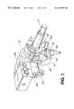
- FIG. 1is a front perspective view of a weapon and aiming system according to a first embodiment of the invention
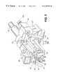
- FIG. 2is a rear perspective view of the weapon of FIG. 1 but with a modified aiming system mounting;
- FIG. 3is a schematic diagram of the weapon and aiming system of FIG. 1 taken from the rear;
- FIG. 4is a schematic system diagram showing the electrical connections between components of the weapon and its aiming system
- FIGS. 5A to 5 Dillustrate images displayed during normal operation of the weapon
- FIG. 6illustrates an image with a modified aiming reticle
- FIGS. 7A to 7 Hillustrate images displayed during operation of the aiming system to predesignate targets, and during engagement of a target after such predesignation
- FIG. 8is a schematic partial view of the weapon and aiming system of FIG. showing details of the modified coupling unit interconnecting them.
- a weapon system embodying the inventioncomprises a weapon body 10 having a barrel 12 mounted in a cradle mount 14 , with an aiming system 16 mounted to one side of the cradle mount 14 .
- the cradle mount 14has upstanding arms 18 and 20 extending one from each side of the weapon body 10 .
- Journals 22 and 24project from opposite sides of the weapon body 10 and into bearings 26 and 28 in arms 18 and 20 , respectively, permitting the weapon to pivot in elevation relative to the cradle mount 14 .
- a tapered pintle 30 fixedly secured in a central base unit 36 of a tripod 38projects upwards through a bearing 32 in a bight portion 34 of cradle mount 14 .
- the cradle 14can rotate in azimuth relative to the tripod 38 .
- Handles 40 at the rear end of the weapon body 10allow the user to pivot the weapon in elevation and azimuth.
- Three control pushbuttons 42 , 44 and 46are disposed adjacent the handles 40 so that they can be operated by the user, as will be described later.
- a trigger 48is positioned between the two handles 40 .
- the aiming system 16comprises a coupling unit 52 and a sight unit 54 which is supported upon the coupling unit 52 .
- a display unit 56is mounted upon the sight unit 54 by means of a rearwardly-extending support arm 58 , so that the display unit 56 is immediately above the rear portion of the weapon body 10 .
- the support arm 58may also carry electrical connections (not shown),
- a support shaft 60extends through bearings 62 and 64 in opposite sidewalls 66 and 68 , respectively, of a housing 70 of the coupling unit 52 .
- the end portion of shaft 60 supported by bearing 62has a tapered hole 72 to receive a mating tapered end portion 74 of journal 24 which projects beyond bearing 28 and cradle 14 .
- the shaft 60thus constitutes a first part of the coupling unit that is connected to the weapon for movement in elevation with the barrel 12 .
- the housing 70constitutes a second part that is connected to the sight unit 54 and an imaging unit 106 thereof (to be described later).
- a first clutch unit 76 acting between the housing 70 and the cradle 14comprises a clutch plate 78 depending from a cantilever arm 80 projecting from the upstanding arm 20 of the cradle mount 14 .
- the clutch plate 78 and arm 80constitute a third part of the coupling unit that is connected to the support 14 .
- a peripheral portion 82 of the clutch plate 78extends between a par of pads 84 and 86 in an operating calliper 88 mounted upon the exterior of the adjacent sidewall 66 of coupling housing 70 . Actuation of the clutch unit 76 locks the housing unit 70 , and hence the sight unit 54 , to the cradle 14 .
- a second clutch unit 90 inside the housing 70comprises a clutch plate 92 depending from the shaft 60 with a peripheral portion 94 extending between a pair of pads 96 and 98 in an operating calliper 100 mounted upon the interior of sidewall 68 Actuation of the clutch unit 90 locks the housing unit 70 , and the sight unit 54 , to the shaft 60 , and hence to the weapon body 10 .
- the clutch units 76 and 90are operated by solenoids (not shown) connected to the control button 42 , which is a changeover switch. Consequently, when one clutch unit is actuated, the other is not.
- clutch unit 76is released and clutch unit 90 engaged, coupling housing 70 is locked to weapon body 10 and so can pivot in elevation relative to the cradle 14 , the elevation angle being measured by an angle encoder, i.e. a resolver 102 , mounted around bearing 64 to measure the angular displacement between the housing 70 and the shaft 60 .
- an angle encoderi.e. a resolver 102
- the aiming system 16will rotate with the weapon body 10 in azimuth as cradle 14 rotates about bearing 32 .
- the azimuthal rotationis measured by a second resolver 104 mounted around the bearing 32 , for providing a signal representing rotation of cradle 14 about pintle 30 which is fixed to the tripod 38 .
- Stopsare provided to limit the movement of the housing 70 relative to the shaft 60 and cradle 14 to predetermined angles.
- the sight unit 54also houses an imaging unit 106 and a laser rangefinder 108 which, together with the resolvers 102 and 104 , and the control buttons 42 , 44 and 46 , are connected to a control computer 110 , also housed in the sight unit 54 .
- the control computer 110also is connected to other sensors 112 which supply data for use, with the range, in calculating the ballistic solution.
- These other sensors 112may include inclinometers mounted in the sight unit 54 for providing signals representing cant and elevation of the imaging unit 106 relative to the ground.
- the control computer unit 110has a memory 114 for storing readings from resolvers 102 and 104 , rangefinder 108 , and other sensors 112 , and is programmed to generate and output the video graphics for the display unit 56 , including graphics artefacts for an aiming reticle 116 and a rangefinder reticle 118 (see FIG. 5 A). It also handles fuse programming, power management for the aiming system, and so on.
- the imaging unit 106is fixed to the sight unit 54 and hence to the second part of the coupling unit 52 , i.e. the housing 70 .
- the imaging device 106may be of the kind which uses a CCD device to capture an electronic image of the field of view, the computer unit 110 including an artefact generator (not shown) for overlaying upon the image, an aiming reticle and a laser rangefinder reticle or spot.
- the computer unit 110would control the artefact generator to position the reticles in the image.
- the imaging device 106might display an optical image with an electronic overlay to provide the electronically-generated aiming reticle and, perhaps, laser rangefinder reticle.
- the position of the laser rangefinder 108 relative to the imaging device 106will be adjusted physically to effect coarse alignment of their sight lines. A more precise calibration will then be made with the imaging device 106 viewing a nearby screen.
- the rangefinder 108will be operated, causing it to illuminate a spot near the aiming reticle.
- the position of the rangefinder reticle 118will be adjusted electronically, using the control computer 110 , to align it with the spot. The coordinates for this position will be stored in the control computer's memory 114 so that the rangefinder reticle 108 will always appear in the same position in the displayed image of the field of view of the imaging device 106 .
- the aiming system 16will be calibrated in the factory and installed onto the weapon afterwards, usually “in the field”. Once the sight unit 54 has been installed onto the weapon, by engaging the tapered portions of the shaft 60 and the journal 24 , it must be “boresighted”. A boresighting device displaying an aiming point marker (not shown) is placed into the barrel 12 and the aiming reticle 106 is adjusted electronically until it is precisely aligned with the aiming point marker. These “datum” coordinates of the aiming reticle 106 are stored in the memory 114 of the control computer 110 . It should be noted that this datum position of the aiming reticle 106 represents a zero-range aiming point or zero-range ballistic solution.
- the position of the aiming reticle 106will be adjusted by the control computer 110 to give the required offset for superelevation and other factors in the ballistic solution. It should be noted that the rangefinder reticle 118 will not be coincident with the aiming reticle 106 in the displayed image, reflecting the fact that the sight line of the rangefinder 108 is offset relative to the sight line of the imaging device 106 .
- FIGS. 5A to 5 DNormal use of the weapon system will now be described with reference to FIGS. 5A to 5 D in which, for purposes of illustration, the image displayed by display unit 56 is shown much simplified.
- the image in display unit 56comprises the scene within the field of view of the imaging device 106 and shows trees 120 and 122 adjacent a roadway 124 along which is travelling a target vehicle 126 .
- the aiming reticle 116 and rangefinder reticle 118are overlaid upon the scene.
- the useroperates switch 42 to engage clutch unit 90 and disengage clutch unit 76 , locking the sight unit 54 to the weapon body 10 .
- the usermoves the weapon body 10 , and with it the laser rangefinder 108 , in azimuth and elevation until the rangefinder reticle 118 is upon the target vehicle 126 , and then depresses pushbutton 44 to operate the rangefinder 108 .
- the control computer 110Upon receipt of the range from the rangefinder 108 , the control computer 110 calculates the ballistic solution including, inter alia, the amount of superelevation required and applies a corresponding offset value to the displacement signal from resolver 102 , causing the aiming reticle 116 to be displaced downwards an equivalent amount, as shown in FIG. 5 B. The user then pivots the weapon barrel 12 upwards, causing the aiming reticle 116 to move upwards as shown in FIG. 5C, positions the aiming reticle 116 upon the target 126 , as shown in FIG. 5D, and fires the weapon by operating trigger 48 .
- the control computer 110does not move the aiming reticle 116 off the screen, but rather moves it until it is adjacent the edge of the display, and hence still visible. In doing so, the control computer 110 applies only part of the superelevation offset to the aiming reticle 116 and stores the balance of the offset in memory 114 . To ensure that the user is aware that the aiming reticle 116 temporarily is not tracking the movement of the barrel 12 , the control computer 110 changes the appearance of the aiming reticle 116 , conveniently by omitting the lower portion of the aiming reticle 116 , as illustrated in FIG. 6, as if part of the aiming reticle 116 were beyond the edge of the display.
- the useroperates switch 42 to engage clutch unit 76 and disengage clutch unit 90 , locking the sight unit 54 to the cradle 14 and disengaging it from the weapon barrel 12 .
- the userthen elevates the barrel 12 , as before, leaving the imaging device 106 stationary, thus keeping the target 126 in view.
- the control computer 110detects that the barrel 12 has been moved upwards by an amount equivalent to the balance of the offset stored in memory, i.e. the aiming point of the barrel 12 corresponds to the position of the aiming reticle 116 at the edge of the display, it restores the aiming reticle 116 to its original appearance and thereafter moves the aiming reticle 116 to track the further upwards movement of the barrel 12 .
- the useradjusts the aiming point in azimuth and elevation until the aiming reticle 116 is upon the vehicle target 126 , and fires the weapon as before.
- the usermay operate switch 42 to lock the sight unit 54 to the weapon body 10 again and move both together until the new target is in view. The user then will repeat the sequence, beginning with the operation of the rangefinder 108 .
- An advantage of embodiments of the present inventionis that, because the target is in view continuously, multiple targets can be engaged in quick succession, especially if they are at approximately the same range. Such a situation might arise, for example, where a number of vehicles are travelling along a path running across the field of view.
- the usermay immediately move the weapon barrel 12 until the aiming reticle 116 is upon another vehicle and fire at that vehicle.
- the usercan check the range of the second vehicle by operating the rangefinder 108 , in which case the control computer 110 will offset the aiming reticle 116 slightly to account for difference between the ranges of the first and second vehicles.
- the clutch 90may remain disengaged, and clutch 76 engaged, while this second vehicle is being targeted.
- the second and any subsequent target vehiclesare within the field of view, they can be engaged in this way without any adjustment of the position of the sight unit 54 , allowing the targets to be engaged in quick succession.
- the clutches 76 and 90can be operated to entrain the sight unit 54 to move with the weapon barrel 12 allowing the user to move the imaging unit 106 until the target is in view again.
- the target acquisition and firing sequencecan then be repeated as before.
- the aiming reticle 116will be offset upwards and the user will have to move the weapon's barrel 12 downwards. It should also be appreciated that the ballistic solution will usually offset the aiming reticle 116 sideways too. In the case of grenade machine guns, however, the offset downwards usually will be much greater.
- the sight unit 54does not need to be moved in the interval between offsetting the aiming reticle 116 and firing the weapon, and the user can keep the target in view, the user can observe any changes in, or movement of, the target while elevating or depressing the weapon barrel to allow for the offsetting of the aiming point.
- the weaponcan be superelevated very quickly because it is only necessary to get the aiming reticle 116 back into the field of view. Thereafter, the user can aim the weapon precisely before firing. This is especially advantageous when aiming at different targets in quick succession.
- the usercould aim the laser rangefinder 108 at the tree 122 immediately adjacent the roadway 124 and determine its range.
- the aiming reticle 116would be displaced downwards as before.
- the control computer 110could be programmed to allow the user to adjust the range reading slightly to compensate for the distance between the tree 122 and the middle of the roadway 124 .
- the target vehicle 126need not be in view when the tree 122 is ranged. While waiting for the vehicle to reach a suitable spot on the roadway 124 , the user could obtain the range of the tree 122 , and even apply any required superelevation to the barrel 12 , allowing quicker engagement when the vehicle 126 arrived at the spot.
- Embodiments of the inventionmay also be used to obtain and store the ranges of predesignated targets, enabling subsequent “blind” engagement of a target, perhaps while it is obscured by smoke, or enabling the user to fire at the predesignated target by a when instructed to do so by a remote “spotter”. Such predesignation will now be described with reference to FIGS. 7A through 7D.
- the userfirst operates pushbutton 46 , which is a four-way toggle switch, to cause the control computer 110 to display a menu (not shown) and selects from it a “predesignation” mode.
- the control computer 110changes the rangefinder reticle 118 to a predesignation icon 128 having the shape of a square minus one quadrant, with a query sign “?” in the space left by the missing quadrant, indicating that the aiming system is in predesignation mode.
- the three quadrant icon 128is preferred because it has a centre defined by converging edges 130 and 132 , which facilitates aiming.
- the control computer 110With the sight unit 54 locked to the weapon, the user moves the weapon until the predesignation reticle 128 is centred upon the first predesignated target, as illustrated in FIGS. 7B and 7C, and operates the laser rangefinder 108 .
- the control computer 110Upon receipt of the range measurement signal, the control computer 110 generates square brackets around the predesignation icon 128 and changes the query sign “?” to a letter “A”, as an identifier for that predesignated target.
- the control computer 110displays the range in a box 134 at the bottom of the display and stores the range in memory 114 , together with the coordinates of the predesignated target A, as derived from the angle encoders 102 and 104 and the elevation inclinometer (not shown) previously mentioned as one the “other sensors” 112 or other gravity sensor which measures elevation relative to the ground.
- the control computer 110may then display a message “ADJUST RANGE” and allow the user to modify the stored range using toggle switch 46 .
- the control computer 110then changes the letter “A” to a query sign “?” again and the user may repeat the procedure for other predesignated targets, storing their ranges and coordinates in the computer's memory 114 , each with a different letter a san identifier.
- a predesignated targetmight be a vehicle 136 , as illustrated, which is not a target itself but occupies a position which later might be occupied by a target vehicle.
- Another exampleis a bridge which, at the time, is empty.
- the control computer 110will detect this and display the predesignation icon 128 at the coordinates of the predesignated target. Assuming that he decides to engage the target, the user places the normal rangefinder reticle 118 upon the predesignated target and operates the rangefinder 108 . As shown in FIG. 7F, the control computer 110 inhibits the operation of the rangefinder 108 and, instead, displays the square brackets around the predesignation icon 128 and the previously-stored range. It also calculates the ballistic solution and offsets the aiming reticle 116 in the usual manner. As shown in FIG. 7G, the user moves the barrel 12 to bring the aiming reticle 116 onto the target and fires the weapon, as illustrated in FIG. 7 H.
- the userwill operate the clutches 76 and 90 as necessary to keep the target in view while acquiring the target and correcting for superelevation offsets.
- FIG. 8illustrates the modified coupling unit 52 ′′, the exterior of which is shown in FIG. 2 and in which the clutch 76 is replaced by a slip clutch 140 which acts continuously to entrain the coupling unit 52 , and with it the sight unit 54 , to maintain its position relative to the cradle 14 .
- the sight unit 54 shown in FIG. 8differs from that illustrated in FIG. 3 in that the bearing 64 is omitted and the shaft 60 stops short of the housing sidewall 68 .
- the angle encoder 102is mounted inside the housing 70 .
- the slip clutch unit 140comprises an annular copper disc 142 secured to the exterior of sidewall 66 and around the shaft 60 .
- a second annular disc 144is mounted upon the opposing wall of the cradle 14 by means of a set of dowels 146 which project from the cradle wall 20 and engage in corresponding holes 148 in the second disc 144 .
- a set of compression springs 150are each mounted around a respective one of the dowels 146 . When the coupling unit 52 is mounted upon the weapon by attaching the shaft 60 to the journal 24 , the springs 150 urge the second disc 144 into contact with the copper disc 142 .
- a layer 152 of suitable friction materialis provided on the surface of the second disc 144 and abuts the copper disc 142 to provide a required amount of friction.
- the second clutch unit 154comprises a clutch plate 156 fixed to a boss 158 on the shaft 60 and depending with its peripheral portion 160 adjacent a single pad 162 fixed to the housing 70 .
- An actuating solenoid 164 mounted upon the housing 70has an armature 166 and an operating coil 168 .
- a spring 170acts between the housing 70 and the armature 166 and, when the coil 168 is de-energized, urges the armature 166 to clamp the clutch plate 156 against the pad 162 .
- the second clutch 154is normally-engaged and overcomes the frictional force exerted by slip clutch 140 so that the coupling unit housing 70 will move with shaft 60 as the weapon barrel 12 is elevated.
- the slip clutch 140will act as a brake, but the frictional force would be set low enough to allow the weapon to move relatively freely as the user moved it to compensate for the offsetting of the aiming reticle 116 .
- the slip clutch 140When the second clutch 154 is disengaged, i.e. when solenoid coil 164 is energized by operation of switch 42 , the slip clutch 140 provides sufficient frictional force to prevent the housing 70 from moving in elevation relative to the cradle 14 as the weapon barrel 12 is elevated by the user.
- clutches 76 , 90 and 154are each described as having a single plate, in practice, they could be multi-plate clutches.
- An advantage of embodiments of the inventionis that the components of the aiming system can be housed in a single housing and quickly and easily mounted upon the weapon.
- a specific advantage of housing the imaging unit 106 and rangefinder 108 togetheris that their relative positions can be fixed and aligned in the factory. This not only avoids adjustments in the field, but also allows the mounting arrangement to be designed so that the alignment is less likely to be lost due to vibration when the unit is in use.
- the inventionhas been described as applied to a military weapon, specifically a grenade machine gun, it is envisaged that it could be applied to other weapons which employ superelevation to launch a projectile.
- the term “weapon”is not limited to military weapons but embraces nonilitary superelevating devices which launch projectiles, such as might be used in construction, or even devices which launch a “projectile” in the form of fluid stream.
Landscapes
- Engineering & Computer Science (AREA)
- General Engineering & Computer Science (AREA)
- Aiming, Guidance, Guns With A Light Source, Armor, Camouflage, And Targets (AREA)
- Telescopes (AREA)
Abstract
Description
Claims (21)
Applications Claiming Priority (2)
| Application Number | Priority Date | Filing Date | Title |
|---|---|---|---|
| CA002245406ACA2245406C (en) | 1998-08-24 | 1998-08-24 | Aiming system for weapon capable of superelevation |
| CA2245406 | 1998-08-24 |
Publications (1)
| Publication Number | Publication Date |
|---|---|
| US6499382B1true US6499382B1 (en) | 2002-12-31 |
Family
ID=4162752
Family Applications (1)
| Application Number | Title | Priority Date | Filing Date |
|---|---|---|---|
| US09/378,720Expired - LifetimeUS6499382B1 (en) | 1998-08-24 | 1999-08-23 | Aiming system for weapon capable of superelevation |
Country Status (2)
| Country | Link |
|---|---|
| US (1) | US6499382B1 (en) |
| CA (1) | CA2245406C (en) |
Cited By (72)
| Publication number | Priority date | Publication date | Assignee | Title |
|---|---|---|---|---|
| US20040134339A1 (en)* | 2001-05-17 | 2004-07-15 | Emile Urvoy | Weapon aiming system |
| US6785996B2 (en)* | 2001-05-24 | 2004-09-07 | R.A. Brands, Llc | Firearm orientation and drop sensor system |
| US20050066807A1 (en)* | 2001-11-19 | 2005-03-31 | Rolf Persson | Weapon sight |
| US20050198885A1 (en)* | 2004-03-10 | 2005-09-15 | Raytheon Company | Weapon sight having multi-munitions ballistics computer |
| US20050241207A1 (en)* | 2004-03-10 | 2005-11-03 | Raytheon Company, A Corporation Of The State Of Delaware | Common aperture time-division-multiplexed laser rangefinder |
| US6973865B1 (en)* | 2003-12-12 | 2005-12-13 | Raytheon Company | Dynamic pointing accuracy evaluation system and method used with a gun that fires a projectile under control of an automated fire control system |
| US20060005447A1 (en)* | 2003-09-12 | 2006-01-12 | Vitronics Inc. | Processor aided firing of small arms |
| US20060010761A1 (en)* | 2004-03-10 | 2006-01-19 | Raytheon Company A Corporation Of The State Of Delaware | Weapon sight having analog on-target indicators |
| US20060048432A1 (en)* | 2004-03-10 | 2006-03-09 | Raytheon Company, A Corporation Of The State Of Delaware | Weapon sight with ballistics information persistence |
| US7021188B1 (en)* | 2003-10-07 | 2006-04-04 | Rafael-Armament Development Authority Ltd. | Grenade launcher with enhanced target follow-up |
| EP1693639A1 (en)* | 2005-01-25 | 2006-08-23 | ITL Optronics Ltd. | Weapon sight assembly and weapon system including same |
| US7131366B2 (en) | 2000-11-13 | 2006-11-07 | Ra Brands, L.L.C. | Actuator assembly |
| US20060272194A1 (en)* | 2005-02-08 | 2006-12-07 | Arnold Guettner | Firearm for low velocity projectiles |
| WO2007030098A1 (en)* | 2005-09-02 | 2007-03-15 | Raytheon Company | Weapon sight having analog on-target indicators |
| JP2007163123A (en)* | 2005-12-05 | 2007-06-28 | Fn Herstal Sa | Improved device for remote control of fire arm |
| JP2007212127A (en)* | 2006-02-08 | 2007-08-23 | Fn Herstal Sa | Improved "moving red dot" sighting device |
| US20070208459A1 (en)* | 2006-03-03 | 2007-09-06 | Samsung Techwin Co., Ltd. | Sentry robot |
| US20070209501A1 (en)* | 2006-03-03 | 2007-09-13 | Samsung Techwin Co., Ltd. | Actuation mechanism having two degrees of freedom and sentry robot having the same |
| US20070214700A1 (en)* | 2006-03-20 | 2007-09-20 | Asia Optical Co., Inc. | Firearm aiming and photographing compound apparatus |
| EP1645833A3 (en)* | 2004-10-06 | 2008-01-23 | S.A.T. Swiss Arms Technology AG | Sighting device for firearm and firearm with mounting possibility for a sighting device |
| EP1923657A1 (en)* | 2006-11-16 | 2008-05-21 | Saab Ab | A compact, fully stabilised, four axes, remote weapon station with independent line of sight |
| US20080192979A1 (en)* | 2006-07-04 | 2008-08-14 | Christopher Bee | Shot pattern and target display |
| US20080282877A1 (en)* | 2004-09-09 | 2008-11-20 | Daniel De Villiers | An Indirect Fire Weapon Aiming Device |
| US7490430B2 (en) | 2004-03-10 | 2009-02-17 | Raytheon Company | Device with multiple sights for respective different munitions |
| US20110261204A1 (en)* | 2010-04-27 | 2011-10-27 | Itt Manufacturing Enterprises, Inc | Remote activation of imagery in night vision goggles |
| US20120000979A1 (en)* | 2010-06-30 | 2012-01-05 | Trijicon, Inc. | Aiming system for weapon |
| US20120145786A1 (en)* | 2010-12-07 | 2012-06-14 | Bae Systems Controls, Inc. | Weapons system and targeting method |
| EP2518432A1 (en)* | 2011-04-29 | 2012-10-31 | LFK-Lenkflugkörpersysteme GmbH | Firearm targeting device, firearm and method for aligning a firearm |
| US20130133510A1 (en)* | 2011-11-30 | 2013-05-30 | General Dynamics Armament And Technical Products, Inc. | Gun sight for use with superelevating weapon |
| US8485085B2 (en)* | 2004-10-12 | 2013-07-16 | Telerobotics Corporation | Network weapon system and method |
| EP2275769A3 (en)* | 2009-07-16 | 2013-11-27 | Rheinmetall Soldier Electronics GmbH | Fire control unit for a handgun |
| WO2013176644A1 (en) | 2012-05-21 | 2013-11-28 | Raytheon Company | Optical super-elevation device |
| US20140028856A1 (en)* | 2011-03-28 | 2014-01-30 | Smart Shooter Ltd. | Firearm, aiming system therefor, method of operating the firearm and method of reducing the probability of missing a target |
| EP2694908A4 (en)* | 2011-04-01 | 2014-10-08 | Zrf Llc | SYSTEM AND METHOD FOR AUTOMATIC SCREENING OF A WEAPON |
| GB2512915A (en)* | 2013-04-11 | 2014-10-15 | Rowan Engineering Ltd | Apparatus for use with a telescopic sight |
| US20150041538A1 (en)* | 2012-02-09 | 2015-02-12 | Wilcox Industries Corp. | Weapon video display system employing smartphone or other portable computing device |
| US9033232B2 (en)* | 2010-08-20 | 2015-05-19 | Rocksight Holdings, Llc | Active stabilization targeting correction for handheld firearms |
| EP2878913A1 (en) | 2013-11-29 | 2015-06-03 | MBDA Deutschland GmbH | Fire control sight, handgun with such a fire control sigth and a method for aiming said handgun |
| US20150226524A1 (en)* | 2013-04-26 | 2015-08-13 | Andrey Borissov Batchvarov | Method of Use to Improve Aiming Accuracy for a Firearm |
| US20160010950A1 (en)* | 1997-12-08 | 2016-01-14 | Horus Vision Llc | Apparatus and method for calculating aiming point information |
| US9243869B1 (en)* | 2011-08-09 | 2016-01-26 | Raytheon Company | Weapon posturing system and methods of use |
| US20160161217A1 (en)* | 2013-03-21 | 2016-06-09 | Kms Consulting, Llc | Apparatus for correcting ballistic errors using laser induced fluorescent (strobe) tracers |
| CN105683706A (en)* | 2013-08-22 | 2016-06-15 | 夏尔特银斯公司 | Laser rangefinder with improved display |
| US20160216071A1 (en)* | 2015-01-23 | 2016-07-28 | Raytheon Company | Method and apparatus for electro-mechanical super-elevation |
| US9404713B2 (en) | 2013-03-15 | 2016-08-02 | General Dynamics Ordnance And Tactical Systems, Inc. | Gun sight for use with superelevating weapon |
| US9464871B2 (en) | 2009-09-11 | 2016-10-11 | Laurence Andrew Bay | System and method for ballistic solutions |
| US20160305740A1 (en)* | 2013-12-13 | 2016-10-20 | Profense, Llc | Gun Control Unit with Computerized Multi-Function Display |
| EP2435778B1 (en) | 2009-05-25 | 2016-10-26 | Rheinmetall Waffe Munition GmbH | Modular weapon carrier |
| DE102015012206A1 (en) | 2015-09-19 | 2017-03-23 | Mbda Deutschland Gmbh | Fire control device for a handgun and handgun |
| US9683813B2 (en) | 2012-09-13 | 2017-06-20 | Christopher V. Beckman | Targeting adjustments to control the impact of breathing, tremor, heartbeat and other accuracy-reducing factors |
| EP2422157B1 (en)* | 2009-04-24 | 2017-06-28 | Agency For Defense Development | Firearm having dual barrels |
| US9746286B2 (en) | 2015-06-09 | 2017-08-29 | William J. Piepmeyer | System and method for target engagement |
| US20170268850A1 (en)* | 2012-01-10 | 2017-09-21 | Hvrt Corp. | Apparatus and method for calculating aiming point information |
| US9823047B2 (en)* | 2010-02-16 | 2017-11-21 | Trackingpoint, Inc. | System and method of controlling discharge of a firearm |
| WO2018045389A1 (en)* | 2016-09-04 | 2018-03-08 | Mccoy Ii Charles A | Precision aiming systems and methods |
| US9927195B2 (en)* | 2013-11-18 | 2018-03-27 | Bae Systems Bofors Ab | Method for direction limitation and system for direction limitation |
| DE102017101118A1 (en) | 2017-01-20 | 2018-07-26 | Steiner-Optik Gmbh | Communication system for transmitting captured object information between at least two communication partners |
| US10054397B1 (en)* | 2015-04-19 | 2018-08-21 | Paul Reimer | Self-correcting scope |
| EP2538166B1 (en) | 2011-06-22 | 2018-09-19 | Diehl Defence GmbH & Co. KG | Fire control device |
| CN109405646A (en)* | 2018-12-27 | 2019-03-01 | 四川红光汽车机电有限公司 | A kind of machine gun control sighting system |
| US10254082B2 (en) | 2013-01-11 | 2019-04-09 | Hvrt Corp. | Apparatus and method for calculating aiming point information |
| US10458754B2 (en)* | 2017-05-15 | 2019-10-29 | T-Worx Holdings, LLC | System and method for networking firearm-mounted devices |
| US10502529B2 (en) | 2009-05-15 | 2019-12-10 | Hvrt Corp. | Apparatus and method for calculating aiming point information |
| EP3569969A3 (en)* | 2015-04-22 | 2020-02-19 | Openworks Engineering Ltd. | System for deploying a first object for capturing, immobilising or disabling a second object |
| US10578402B1 (en) | 2016-11-10 | 2020-03-03 | II Charles A. McCoy | Level indicator for aiming systems |
| CN111272014A (en)* | 2019-12-31 | 2020-06-12 | 北京晶品特装科技有限责任公司 | Fire control calculation control system and method based on dynamic scale |
| US10823532B2 (en) | 2018-09-04 | 2020-11-03 | Hvrt Corp. | Reticles, methods of use and manufacture |
| US11092437B1 (en) | 2020-06-18 | 2021-08-17 | Flatline Ops, Inc. | Level indicator for telescopic sights |
| US11118866B2 (en) | 2018-10-22 | 2021-09-14 | Hanwha Defense Co., Ltd. | Apparatus and method for controlling striking apparatus and remote controlled weapon system |
| US11313649B1 (en) | 2020-07-31 | 2022-04-26 | Ryan Johnson | Elevation range meter and method of ranging a target using said elevation range meter |
| US20230235992A1 (en)* | 2014-09-19 | 2023-07-27 | Philip Lyren | Weapon Targeting System |
| PL443563A1 (en)* | 2023-06-16 | 2024-12-23 | Karol Tomczyk | Optical-electronic sight for assault rifles |
Families Citing this family (1)
| Publication number | Priority date | Publication date | Assignee | Title |
|---|---|---|---|---|
| DK1304539T3 (en) | 2001-10-12 | 2005-12-12 | Contraves Ag | Method and device for setting up a gun barrel and using the device |
Citations (12)
| Publication number | Priority date | Publication date | Assignee | Title |
|---|---|---|---|---|
| US2284611A (en) | 1939-11-14 | 1942-05-26 | George E Barnhart | Remotely controlled gun mount |
| US2359032A (en) | 1939-04-26 | 1944-09-26 | Edgar N Gott | Remote visual control system |
| US2570298A (en)* | 1945-12-19 | 1951-10-09 | Wheeler Phillip Rood | Gyroscopically controlled electrical gun sight |
| US3710675A (en) | 1969-12-12 | 1973-01-16 | Tampella Oy Ab | Aiming arrangement for grenade throwers |
| US3766826A (en) | 1971-02-26 | 1973-10-23 | Bofors Ab | Device for achieving aim-off for a firearm |
| US3824699A (en) | 1972-06-19 | 1974-07-23 | Us Army | Aiming device for indirect fire guns |
| US4193334A (en) | 1978-07-31 | 1980-03-18 | Cadillac Gage Company | Gun sight positioning mechanism |
| US4577546A (en) | 1983-11-21 | 1986-03-25 | Ex-Cell-O Corporation | Gun sight range extender |
| US4760770A (en)* | 1982-11-17 | 1988-08-02 | Barr & Stroud Limited | Fire control systems |
| US4787291A (en) | 1986-10-02 | 1988-11-29 | Hughes Aircraft Company | Gun fire control system |
| US5686690A (en) | 1992-12-02 | 1997-11-11 | Computing Devices Canada Ltd. | Weapon aiming system |
| US5949015A (en)* | 1997-05-14 | 1999-09-07 | Kollmorgen Corporation | Weapon control system having weapon stabilization |
- 1998
- 1998-08-24CACA002245406Apatent/CA2245406C/ennot_activeExpired - Lifetime
- 1999
- 1999-08-23USUS09/378,720patent/US6499382B1/ennot_activeExpired - Lifetime
Patent Citations (12)
| Publication number | Priority date | Publication date | Assignee | Title |
|---|---|---|---|---|
| US2359032A (en) | 1939-04-26 | 1944-09-26 | Edgar N Gott | Remote visual control system |
| US2284611A (en) | 1939-11-14 | 1942-05-26 | George E Barnhart | Remotely controlled gun mount |
| US2570298A (en)* | 1945-12-19 | 1951-10-09 | Wheeler Phillip Rood | Gyroscopically controlled electrical gun sight |
| US3710675A (en) | 1969-12-12 | 1973-01-16 | Tampella Oy Ab | Aiming arrangement for grenade throwers |
| US3766826A (en) | 1971-02-26 | 1973-10-23 | Bofors Ab | Device for achieving aim-off for a firearm |
| US3824699A (en) | 1972-06-19 | 1974-07-23 | Us Army | Aiming device for indirect fire guns |
| US4193334A (en) | 1978-07-31 | 1980-03-18 | Cadillac Gage Company | Gun sight positioning mechanism |
| US4760770A (en)* | 1982-11-17 | 1988-08-02 | Barr & Stroud Limited | Fire control systems |
| US4577546A (en) | 1983-11-21 | 1986-03-25 | Ex-Cell-O Corporation | Gun sight range extender |
| US4787291A (en) | 1986-10-02 | 1988-11-29 | Hughes Aircraft Company | Gun fire control system |
| US5686690A (en) | 1992-12-02 | 1997-11-11 | Computing Devices Canada Ltd. | Weapon aiming system |
| US5949015A (en)* | 1997-05-14 | 1999-09-07 | Kollmorgen Corporation | Weapon control system having weapon stabilization |
Non-Patent Citations (3)
| Title |
|---|
| ML19 Mod 3 40mm Daylight Optic & Adjustable Sight/Bracket, Saco Defense Incorporated. |
| New Grenade Launcher Offers First Shot Hits, Greater Lethality via Smart Ammo, Virgina Hart Ezell, Nation Defence Feb. 1998. p. 46. |
| WIth SACMFRCS, Their First Move . . . will be Their Last, EOS Electro-Optics Systems, Contraves2004/92 4 pages. |
Cited By (146)
| Publication number | Priority date | Publication date | Assignee | Title |
|---|---|---|---|---|
| US20160010950A1 (en)* | 1997-12-08 | 2016-01-14 | Horus Vision Llc | Apparatus and method for calculating aiming point information |
| US7131366B2 (en) | 2000-11-13 | 2006-11-07 | Ra Brands, L.L.C. | Actuator assembly |
| US6935218B2 (en)* | 2001-05-17 | 2005-08-30 | Giat Industries | Weapon aiming system |
| US20040134339A1 (en)* | 2001-05-17 | 2004-07-15 | Emile Urvoy | Weapon aiming system |
| US6785996B2 (en)* | 2001-05-24 | 2004-09-07 | R.A. Brands, Llc | Firearm orientation and drop sensor system |
| US7188444B2 (en) | 2001-05-24 | 2007-03-13 | Ra Brands, L.L.C. | Firearm orientation and drop sensor system |
| US20060277808A1 (en)* | 2001-05-24 | 2006-12-14 | R. A. Brands, Llc. | Firearm orientation and drop sensor system |
| US7698986B2 (en) | 2001-11-19 | 2010-04-20 | Bofors Defence Ab | Weapon sight |
| US8365650B2 (en) | 2001-11-19 | 2013-02-05 | Bae Systems Bofors Ab | Weapon sight |
| US20080053302A1 (en)* | 2001-11-19 | 2008-03-06 | Bae Systems Bofors Ab | Weapon sight |
| US7293493B2 (en)* | 2001-11-19 | 2007-11-13 | Bae Systems Bofors Ab | Weapon sight |
| US20090025545A1 (en)* | 2001-11-19 | 2009-01-29 | Bae Systems Bofors Ab | Weapon sight |
| US7487705B2 (en) | 2001-11-19 | 2009-02-10 | Bae Systems Bofors Ab | Weapon sight |
| US20050066807A1 (en)* | 2001-11-19 | 2005-03-31 | Rolf Persson | Weapon sight |
| US20060005447A1 (en)* | 2003-09-12 | 2006-01-12 | Vitronics Inc. | Processor aided firing of small arms |
| US7021188B1 (en)* | 2003-10-07 | 2006-04-04 | Rafael-Armament Development Authority Ltd. | Grenade launcher with enhanced target follow-up |
| US10295307B2 (en) | 2003-11-12 | 2019-05-21 | Hvrt Corp. | Apparatus and method for calculating aiming point information |
| US10731948B2 (en) | 2003-11-12 | 2020-08-04 | Hvrt Corp. | Apparatus and method for calculating aiming point information |
| US6973865B1 (en)* | 2003-12-12 | 2005-12-13 | Raytheon Company | Dynamic pointing accuracy evaluation system and method used with a gun that fires a projectile under control of an automated fire control system |
| US20060048432A1 (en)* | 2004-03-10 | 2006-03-09 | Raytheon Company, A Corporation Of The State Of Delaware | Weapon sight with ballistics information persistence |
| US20050241207A1 (en)* | 2004-03-10 | 2005-11-03 | Raytheon Company, A Corporation Of The State Of Delaware | Common aperture time-division-multiplexed laser rangefinder |
| US20050198885A1 (en)* | 2004-03-10 | 2005-09-15 | Raytheon Company | Weapon sight having multi-munitions ballistics computer |
| US7269920B2 (en) | 2004-03-10 | 2007-09-18 | Raytheon Company | Weapon sight with ballistics information persistence |
| US7171776B2 (en) | 2004-03-10 | 2007-02-06 | Raytheon Company | Weapon sight having analog on-target indicators |
| US7490430B2 (en) | 2004-03-10 | 2009-02-17 | Raytheon Company | Device with multiple sights for respective different munitions |
| US8056281B2 (en) | 2004-03-10 | 2011-11-15 | Raytheon Company | Device with multiple sights for respective different munitions |
| US20060010761A1 (en)* | 2004-03-10 | 2006-01-19 | Raytheon Company A Corporation Of The State Of Delaware | Weapon sight having analog on-target indicators |
| US8375620B2 (en) | 2004-03-10 | 2013-02-19 | Raytheon Company | Weapon sight having multi-munitions ballistics computer |
| US20080282877A1 (en)* | 2004-09-09 | 2008-11-20 | Daniel De Villiers | An Indirect Fire Weapon Aiming Device |
| US7637198B2 (en)* | 2004-09-09 | 2009-12-29 | Csir | Indirect fire weapon aiming device |
| EP1645833A3 (en)* | 2004-10-06 | 2008-01-23 | S.A.T. Swiss Arms Technology AG | Sighting device for firearm and firearm with mounting possibility for a sighting device |
| US8485085B2 (en)* | 2004-10-12 | 2013-07-16 | Telerobotics Corporation | Network weapon system and method |
| US20080094473A1 (en)* | 2005-01-25 | 2008-04-24 | Itl Optronics Ltd. | Weapon sight assembly and weapon system including same |
| EP1693639A1 (en)* | 2005-01-25 | 2006-08-23 | ITL Optronics Ltd. | Weapon sight assembly and weapon system including same |
| US20060272194A1 (en)* | 2005-02-08 | 2006-12-07 | Arnold Guettner | Firearm for low velocity projectiles |
| WO2007030098A1 (en)* | 2005-09-02 | 2007-03-15 | Raytheon Company | Weapon sight having analog on-target indicators |
| US20070261544A1 (en)* | 2005-12-05 | 2007-11-15 | Plumier Philippe | Device for the remote control of a fire arm |
| JP2007163123A (en)* | 2005-12-05 | 2007-06-28 | Fn Herstal Sa | Improved device for remote control of fire arm |
| AU2006249203B2 (en)* | 2005-12-05 | 2011-11-10 | Fn Herstal S.A. | Improved device for the remote control of a fire arm |
| US7509904B2 (en)* | 2005-12-05 | 2009-03-31 | Fn Herstal S.A. | Device for the remote control of a firearm |
| JP2007212127A (en)* | 2006-02-08 | 2007-08-23 | Fn Herstal Sa | Improved "moving red dot" sighting device |
| US8029198B2 (en)* | 2006-03-03 | 2011-10-04 | Samsung Techwin Co., Ltd. | Actuation mechanism having two degrees of freedom and sentry robot having the same |
| US20070208459A1 (en)* | 2006-03-03 | 2007-09-06 | Samsung Techwin Co., Ltd. | Sentry robot |
| US20070209501A1 (en)* | 2006-03-03 | 2007-09-13 | Samsung Techwin Co., Ltd. | Actuation mechanism having two degrees of freedom and sentry robot having the same |
| US20070214700A1 (en)* | 2006-03-20 | 2007-09-20 | Asia Optical Co., Inc. | Firearm aiming and photographing compound apparatus |
| US7437848B2 (en)* | 2006-03-20 | 2008-10-21 | Asia Optical Co., Inc. | Firearm aiming and photographing compound apparatus |
| US20080192979A1 (en)* | 2006-07-04 | 2008-08-14 | Christopher Bee | Shot pattern and target display |
| US20080148931A1 (en)* | 2006-11-16 | 2008-06-26 | Saab Ab | Compact, fully stablised, four axes, remote weapon station with independent line of sight |
| EP1923657A1 (en)* | 2006-11-16 | 2008-05-21 | Saab Ab | A compact, fully stabilised, four axes, remote weapon station with independent line of sight |
| EP2422157B1 (en)* | 2009-04-24 | 2017-06-28 | Agency For Defense Development | Firearm having dual barrels |
| US10502529B2 (en) | 2009-05-15 | 2019-12-10 | Hvrt Corp. | Apparatus and method for calculating aiming point information |
| US10948265B2 (en) | 2009-05-15 | 2021-03-16 | Hvrt Corp. | Apparatus and method for calculating aiming point information |
| US11421961B2 (en) | 2009-05-15 | 2022-08-23 | Hvrt Corp. | Apparatus and method for calculating aiming point information |
| EP2435778B1 (en) | 2009-05-25 | 2016-10-26 | Rheinmetall Waffe Munition GmbH | Modular weapon carrier |
| EP2275769A3 (en)* | 2009-07-16 | 2013-11-27 | Rheinmetall Soldier Electronics GmbH | Fire control unit for a handgun |
| US9464871B2 (en) | 2009-09-11 | 2016-10-11 | Laurence Andrew Bay | System and method for ballistic solutions |
| US9823047B2 (en)* | 2010-02-16 | 2017-11-21 | Trackingpoint, Inc. | System and method of controlling discharge of a firearm |
| US20110261204A1 (en)* | 2010-04-27 | 2011-10-27 | Itt Manufacturing Enterprises, Inc | Remote activation of imagery in night vision goggles |
| US20120000979A1 (en)* | 2010-06-30 | 2012-01-05 | Trijicon, Inc. | Aiming system for weapon |
| US8336776B2 (en)* | 2010-06-30 | 2012-12-25 | Trijicon, Inc. | Aiming system for weapon |
| US9033232B2 (en)* | 2010-08-20 | 2015-05-19 | Rocksight Holdings, Llc | Active stabilization targeting correction for handheld firearms |
| US20120145786A1 (en)* | 2010-12-07 | 2012-06-14 | Bae Systems Controls, Inc. | Weapons system and targeting method |
| US8245623B2 (en)* | 2010-12-07 | 2012-08-21 | Bae Systems Controls Inc. | Weapons system and targeting method |
| US10097764B2 (en)* | 2011-03-28 | 2018-10-09 | Smart Shooter Ltd. | Firearm, aiming system therefor, method of operating the firearm and method of reducing the probability of missing a target |
| US20140028856A1 (en)* | 2011-03-28 | 2014-01-30 | Smart Shooter Ltd. | Firearm, aiming system therefor, method of operating the firearm and method of reducing the probability of missing a target |
| EP2694908A4 (en)* | 2011-04-01 | 2014-10-08 | Zrf Llc | SYSTEM AND METHOD FOR AUTOMATIC SCREENING OF A WEAPON |
| US9310163B2 (en) | 2011-04-01 | 2016-04-12 | Laurence Andrew Bay | System and method for automatically targeting a weapon |
| EP2518432A1 (en)* | 2011-04-29 | 2012-10-31 | LFK-Lenkflugkörpersysteme GmbH | Firearm targeting device, firearm and method for aligning a firearm |
| EP2634523A1 (en)* | 2011-04-29 | 2013-09-04 | MBDA Deutschland GmbH | Firearm targeting device, firearm and method for aligning a firearm |
| EP2538166B1 (en) | 2011-06-22 | 2018-09-19 | Diehl Defence GmbH & Co. KG | Fire control device |
| US9243869B1 (en)* | 2011-08-09 | 2016-01-26 | Raytheon Company | Weapon posturing system and methods of use |
| US9052158B2 (en) | 2011-11-30 | 2015-06-09 | General Dynamics—OTS, Inc. | Gun sight for use with superelevating weapon |
| US9057581B2 (en)* | 2011-11-30 | 2015-06-16 | General Dynamics-Ots, Inc. | Gun sight for use with superelevating weapon |
| WO2013126110A3 (en)* | 2011-11-30 | 2013-10-17 | General Dynamics Armament And Technical Products, Inc. | Gun sight for use with superelevating weapon |
| WO2013126112A3 (en)* | 2011-11-30 | 2013-10-17 | General Dynamics Armament And Technical Products, Inc. | Gun sight for use with superelevating weapon |
| US20130133510A1 (en)* | 2011-11-30 | 2013-05-30 | General Dynamics Armament And Technical Products, Inc. | Gun sight for use with superelevating weapon |
| US10488153B2 (en)* | 2012-01-10 | 2019-11-26 | Hvrt Corp. | Apparatus and method for calculating aiming point information |
| US20170268850A1 (en)* | 2012-01-10 | 2017-09-21 | Hvrt Corp. | Apparatus and method for calculating aiming point information |
| US11181342B2 (en) | 2012-01-10 | 2021-11-23 | Hvrt Corp. | Apparatus and method for calculating aiming point information |
| US10488154B2 (en)* | 2012-01-10 | 2019-11-26 | Hvrt Corp. | Apparatus and method for calculating aiming point information |
| US11391542B2 (en) | 2012-01-10 | 2022-07-19 | Hvrt Corp. | Apparatus and method for calculating aiming point information |
| US20240418479A1 (en)* | 2012-01-10 | 2024-12-19 | Hvrt Corp. | Apparatus and method for calculating aiming point information |
| US10451385B2 (en)* | 2012-01-10 | 2019-10-22 | Hvrt Corp. | Apparatus and method for calculating aiming point information |
| US11965711B2 (en) | 2012-01-10 | 2024-04-23 | Hvrt Corp. | Apparatus and method for calculating aiming point information |
| US20150041538A1 (en)* | 2012-02-09 | 2015-02-12 | Wilcox Industries Corp. | Weapon video display system employing smartphone or other portable computing device |
| US8978539B2 (en)* | 2012-02-09 | 2015-03-17 | Wilcox Industries Corp. | Weapon video display system employing smartphone or other portable computing device |
| WO2013176644A1 (en) | 2012-05-21 | 2013-11-28 | Raytheon Company | Optical super-elevation device |
| US9383168B2 (en) | 2012-05-21 | 2016-07-05 | Raytheon Company | Optical super-elevation device |
| US9683813B2 (en) | 2012-09-13 | 2017-06-20 | Christopher V. Beckman | Targeting adjustments to control the impact of breathing, tremor, heartbeat and other accuracy-reducing factors |
| US11656060B2 (en) | 2013-01-11 | 2023-05-23 | Hvrt Corp. | Apparatus and method for calculating aiming point information |
| US11255640B2 (en) | 2013-01-11 | 2022-02-22 | Hvrt Corp. | Apparatus and method for calculating aiming point information |
| US10895434B2 (en) | 2013-01-11 | 2021-01-19 | Hvrt Corp. | Apparatus and method for calculating aiming point information |
| US10458753B2 (en) | 2013-01-11 | 2019-10-29 | Hvrt Corp. | Apparatus and method for calculating aiming point information |
| US10254082B2 (en) | 2013-01-11 | 2019-04-09 | Hvrt Corp. | Apparatus and method for calculating aiming point information |
| US9404713B2 (en) | 2013-03-15 | 2016-08-02 | General Dynamics Ordnance And Tactical Systems, Inc. | Gun sight for use with superelevating weapon |
| EP2972055A4 (en)* | 2013-03-15 | 2016-08-10 | Gen Dynamics Ordnance & Tactic | VIEWFINDER FOR USE WITH A WEAPON IN A SITUATION OF ALLEVIATION |
| US20160161217A1 (en)* | 2013-03-21 | 2016-06-09 | Kms Consulting, Llc | Apparatus for correcting ballistic errors using laser induced fluorescent (strobe) tracers |
| US20190025014A1 (en)* | 2013-03-21 | 2019-01-24 | Kevin Michael Sullivan | Apparatus for correcting ballistic aim errors using special tracers |
| US10648775B2 (en)* | 2013-03-21 | 2020-05-12 | Nostromo Holdings, Llc | Apparatus for correcting ballistic aim errors using special tracers |
| GB2512915A (en)* | 2013-04-11 | 2014-10-15 | Rowan Engineering Ltd | Apparatus for use with a telescopic sight |
| US20150226524A1 (en)* | 2013-04-26 | 2015-08-13 | Andrey Borissov Batchvarov | Method of Use to Improve Aiming Accuracy for a Firearm |
| EP3036504A4 (en)* | 2013-08-22 | 2017-04-26 | Hamilton, David, M. | Laser rangefinder with improved display |
| CN105683706A (en)* | 2013-08-22 | 2016-06-15 | 夏尔特银斯公司 | Laser rangefinder with improved display |
| CN112229371B (en)* | 2013-08-22 | 2023-10-24 | 夏尔特银斯公司 | Laser rangefinder with improved display |
| JP2016540213A (en)* | 2013-08-22 | 2016-12-22 | シェルタード ウィングス, インコーポレイテッドSheltered Wings, Inc. | Laser rangefinder with improved display |
| CN105683706B (en)* | 2013-08-22 | 2020-11-06 | 夏尔特银斯公司 | Laser rangefinder with improved display |
| JP2021076370A (en)* | 2013-08-22 | 2021-05-20 | シェルタード ウィングス, インコーポレイテッドSheltered Wings, Inc. | Laser distance meter having improved display |
| CN112229371A (en)* | 2013-08-22 | 2021-01-15 | 夏尔特银斯公司 | Laser rangefinder with improved display |
| US9927195B2 (en)* | 2013-11-18 | 2018-03-27 | Bae Systems Bofors Ab | Method for direction limitation and system for direction limitation |
| US9395156B2 (en) | 2013-11-29 | 2016-07-19 | Mbda Deutschland Gmbh | Fire control sight, hand-held firearm and a method for orienting a hand-held firearm |
| EP2878913A1 (en) | 2013-11-29 | 2015-06-03 | MBDA Deutschland GmbH | Fire control sight, handgun with such a fire control sigth and a method for aiming said handgun |
| DE102014001028A1 (en) | 2013-11-29 | 2015-06-03 | Mbda Deutschland Gmbh | Fire control visor, handgun and a method for aligning a handgun |
| DE102014001028B4 (en) | 2013-11-29 | 2018-09-13 | Mbda Deutschland Gmbh | Fire control visor, handgun and a method for aligning a handgun |
| US20160305740A1 (en)* | 2013-12-13 | 2016-10-20 | Profense, Llc | Gun Control Unit with Computerized Multi-Function Display |
| US20230235992A1 (en)* | 2014-09-19 | 2023-07-27 | Philip Lyren | Weapon Targeting System |
| US12085367B2 (en)* | 2014-09-19 | 2024-09-10 | Philip Lyren | Weapon targeting system |
| US20160216071A1 (en)* | 2015-01-23 | 2016-07-28 | Raytheon Company | Method and apparatus for electro-mechanical super-elevation |
| US10488155B2 (en)* | 2015-01-23 | 2019-11-26 | Raytheon Company | Method and apparatus for electro-mechanical super-elevation |
| US10054397B1 (en)* | 2015-04-19 | 2018-08-21 | Paul Reimer | Self-correcting scope |
| EP3569969A3 (en)* | 2015-04-22 | 2020-02-19 | Openworks Engineering Ltd. | System for deploying a first object for capturing, immobilising or disabling a second object |
| US10871353B2 (en) | 2015-04-22 | 2020-12-22 | Openworks Engineering Ltd | System for deploying a first object for capturing, immobilising or disabling a second object |
| US9746286B2 (en) | 2015-06-09 | 2017-08-29 | William J. Piepmeyer | System and method for target engagement |
| US10082366B2 (en) | 2015-09-19 | 2018-09-25 | Mbda Deutschland Gmbh | Fire-control device for a small arm and small arm |
| DE102015012206A1 (en) | 2015-09-19 | 2017-03-23 | Mbda Deutschland Gmbh | Fire control device for a handgun and handgun |
| EP3150956A1 (en) | 2015-09-19 | 2017-04-05 | MBDA Deutschland GmbH | Fire guide device for a handgun and a handgun |
| WO2018045389A1 (en)* | 2016-09-04 | 2018-03-08 | Mccoy Ii Charles A | Precision aiming systems and methods |
| US10914553B2 (en) | 2016-11-10 | 2021-02-09 | Flatline Ops, Inc. | Level indicator for aiming systems |
| US10578402B1 (en) | 2016-11-10 | 2020-03-03 | II Charles A. McCoy | Level indicator for aiming systems |
| US11204221B2 (en) | 2017-01-20 | 2021-12-21 | Steiner-Optik Gmbh | Communication system for transmitting captured object information between at least two communication partners |
| US10852101B2 (en) | 2017-01-20 | 2020-12-01 | Steiner-Optik Gmbh | Communication system for transmitting captured object information between at least two communication partners |
| DE102017101118A1 (en) | 2017-01-20 | 2018-07-26 | Steiner-Optik Gmbh | Communication system for transmitting captured object information between at least two communication partners |
| US11231253B2 (en) | 2017-05-15 | 2022-01-25 | T-Worx Holdings, LLC | System and method for networking firearm-mounted devices |
| US10458754B2 (en)* | 2017-05-15 | 2019-10-29 | T-Worx Holdings, LLC | System and method for networking firearm-mounted devices |
| US11692794B2 (en) | 2017-05-15 | 2023-07-04 | T-Worx Holdings, LLC | System and method for networking firearm-mounted devices |
| US10823532B2 (en) | 2018-09-04 | 2020-11-03 | Hvrt Corp. | Reticles, methods of use and manufacture |
| US11293720B2 (en) | 2018-09-04 | 2022-04-05 | Hvrt Corp. | Reticles, methods of use and manufacture |
| US10895433B2 (en) | 2018-09-04 | 2021-01-19 | Hvrt Corp. | Reticles, methods of use and manufacture |
| US11118866B2 (en) | 2018-10-22 | 2021-09-14 | Hanwha Defense Co., Ltd. | Apparatus and method for controlling striking apparatus and remote controlled weapon system |
| CN109405646A (en)* | 2018-12-27 | 2019-03-01 | 四川红光汽车机电有限公司 | A kind of machine gun control sighting system |
| CN109405646B (en)* | 2018-12-27 | 2023-10-13 | 四川红光汽车机电有限公司 | Machine gun control aiming system |
| CN111272014B (en)* | 2019-12-31 | 2022-05-31 | 北京晶品特装科技股份有限公司 | Fire control calculation control system and method based on dynamic scale |
| CN111272014A (en)* | 2019-12-31 | 2020-06-12 | 北京晶品特装科技有限责任公司 | Fire control calculation control system and method based on dynamic scale |
| US11365968B2 (en) | 2020-06-18 | 2022-06-21 | Flatline Ops, Inc. | Level indicator for telescopic sights |
| US11092437B1 (en) | 2020-06-18 | 2021-08-17 | Flatline Ops, Inc. | Level indicator for telescopic sights |
| US11313649B1 (en) | 2020-07-31 | 2022-04-26 | Ryan Johnson | Elevation range meter and method of ranging a target using said elevation range meter |
| PL443563A1 (en)* | 2023-06-16 | 2024-12-23 | Karol Tomczyk | Optical-electronic sight for assault rifles |
Also Published As
| Publication number | Publication date |
|---|---|
| CA2245406A1 (en) | 2000-02-24 |
| CA2245406C (en) | 2006-12-05 |
Similar Documents
| Publication | Publication Date | Title |
|---|---|---|
| US6499382B1 (en) | Aiming system for weapon capable of superelevation | |
| AU2012370428B2 (en) | Gun sight for use with superelevating weapon | |
| US6252706B1 (en) | Telescopic sight for individual weapon with automatic aiming and adjustment | |
| US7493846B2 (en) | Dual elevation weapon station and method of use | |
| KR920006525B1 (en) | Gun fire control system | |
| AU724543B2 (en) | Military range scoring system | |
| US11781834B2 (en) | Fire control system | |
| TW200839172A (en) | Electronic sight for firearm, and method of operating same | |
| US4742390A (en) | Elevatable observation and target system for combat vehicles | |
| US4789339A (en) | Gunnery training system | |
| US7677893B2 (en) | Training simulator for sharp shooting | |
| CA2280647C (en) | Aiming system for weapon capable of superelevation | |
| EP2972055B1 (en) | Gun sight for use with superelevating weapon | |
| GB2183315A (en) | Determining gun muzzle displacement |
Legal Events
| Date | Code | Title | Description |
|---|---|---|---|
| AS | Assignment | Owner name:GENERAL DYNAMICS CANADA LTD., CANADA Free format text:ASSIGNMENT OF ASSIGNORS INTEREST;ASSIGNORS:LOUGHEED, JAMES HUGH;BOTTOMLEY, THOMAS MARK WALTER;SHAW, STEPHEN DAVID;AND OTHERS;REEL/FRAME:013235/0755;SIGNING DATES FROM 20021024 TO 20021108 | |
| STCF | Information on status: patent grant | Free format text:PATENTED CASE | |
| AS | Assignment | Owner name:RAYTHEON COMPANY, MASSACHUSETTS Free format text:ASSIGNMENT OF ASSIGNORS INTEREST;ASSIGNOR:GENERAL DYNAMICS CANADA LTD.;REEL/FRAME:015442/0617 Effective date:20021213 | |
| AS | Assignment | Owner name:RAYTHEON COMPANY, MASSACHUSETTS Free format text:CORRECTION OF ASSIGNMENT RECORDED 06/14/2004 REEL 015442, FRAME 01617.;ASSIGNOR:GENERAL DYNAMICS CANADA LTD;REEL/FRAME:016153/0488 Effective date:20021213 | |
| FPAY | Fee payment | Year of fee payment:4 | |
| FEPP | Fee payment procedure | Free format text:PAYOR NUMBER ASSIGNED (ORIGINAL EVENT CODE: ASPN); ENTITY STATUS OF PATENT OWNER: LARGE ENTITY | |
| FPAY | Fee payment | Year of fee payment:8 | |
| FPAY | Fee payment | Year of fee payment:12 |