US6498674B1 - Rotating element sheet material with generalized containment structure - Google Patents
Rotating element sheet material with generalized containment structureDownload PDFInfo
- Publication number
- US6498674B1 US6498674B1US09/549,518US54951800AUS6498674B1US 6498674 B1US6498674 B1US 6498674B1US 54951800 AUS54951800 AUS 54951800AUS 6498674 B1US6498674 B1US 6498674B1
- Authority
- US
- United States
- Prior art keywords
- fibrous matrix
- fibrous
- rotatable elements
- rotating element
- fibers
- Prior art date
- Legal status (The legal status is an assumption and is not a legal conclusion. Google has not performed a legal analysis and makes no representation as to the accuracy of the status listed.)
- Expired - Lifetime
Links
- 239000000463materialSubstances0.000titleclaimsabstractdescription190
- 239000011159matrix materialSubstances0.000claimsabstractdescription172
- 239000012530fluidSubstances0.000claimsabstractdescription97
- 238000000034methodMethods0.000claimsabstractdescription80
- 239000003094microcapsuleSubstances0.000claimsabstractdescription65
- 239000000835fiberSubstances0.000claimsdescription58
- 239000002657fibrous materialSubstances0.000claimsdescription46
- 229920002301cellulose acetatePolymers0.000claimsdescription16
- 238000010099solid formingMethods0.000claimsdescription13
- 239000003365glass fiberSubstances0.000claimsdescription12
- 239000005388borosilicate glassSubstances0.000claimsdescription11
- 239000012780transparent materialSubstances0.000claimsdescription6
- 230000004044responseEffects0.000claimsdescription5
- 229920002972Acrylic fiberPolymers0.000claims8
- 230000005670electromagnetic radiationEffects0.000claims2
- 239000011796hollow space materialSubstances0.000abstract2
- 230000006870functionEffects0.000description27
- 238000000576coating methodMethods0.000description26
- 239000011248coating agentSubstances0.000description24
- 239000000758substrateSubstances0.000description16
- 238000004049embossingMethods0.000description12
- 239000013055pulp slurrySubstances0.000description12
- CSCPPACGZOOCGX-UHFFFAOYSA-NAcetoneChemical compoundCC(C)=OCSCPPACGZOOCGX-UHFFFAOYSA-N0.000description8
- 239000004593EpoxySubstances0.000description8
- 210000003722extracellular fluidAnatomy0.000description7
- 239000011521glassSubstances0.000description7
- 230000008859changeEffects0.000description6
- 238000003825pressingMethods0.000description6
- 239000004698PolyethyleneSubstances0.000description5
- -1polyethylenePolymers0.000description5
- 229920000573polyethylenePolymers0.000description5
- GWEVSGVZZGPLCZ-UHFFFAOYSA-NTitan oxideChemical compoundO=[Ti]=OGWEVSGVZZGPLCZ-UHFFFAOYSA-N0.000description4
- 229920002678cellulosePolymers0.000description4
- 239000001913celluloseSubstances0.000description4
- 238000001035dryingMethods0.000description4
- 230000005684electric fieldEffects0.000description4
- 239000004744fabricSubstances0.000description4
- 238000010030laminatingMethods0.000description4
- 239000007788liquidSubstances0.000description4
- 238000004519manufacturing processMethods0.000description4
- 229920002379silicone rubberPolymers0.000description4
- 239000004945silicone rubberSubstances0.000description4
- 238000005728strengtheningMethods0.000description4
- 238000009941weavingMethods0.000description4
- UHOVQNZJYSORNB-UHFFFAOYSA-NBenzeneChemical compoundC1=CC=CC=C1UHOVQNZJYSORNB-UHFFFAOYSA-N0.000description3
- 238000010521absorption reactionMethods0.000description3
- 229920001971elastomerPolymers0.000description3
- 239000000806elastomerSubstances0.000description3
- 238000010438heat treatmentMethods0.000description3
- 230000008569processEffects0.000description3
- 238000001228spectrumMethods0.000description3
- 238000001429visible spectrumMethods0.000description3
- 230000005540biological transmissionEffects0.000description2
- 239000013078crystalSubstances0.000description2
- 230000005686electrostatic fieldEffects0.000description2
- 238000005538encapsulationMethods0.000description2
- 230000005484gravityEffects0.000description2
- 239000004033plasticSubstances0.000description2
- 229920003023plasticPolymers0.000description2
- 239000002985plastic filmSubstances0.000description2
- 229920000728polyesterPolymers0.000description2
- 229920000642polymerPolymers0.000description2
- 229920005594polymer fiberPolymers0.000description2
- 238000002360preparation methodMethods0.000description2
- OGIDPMRJRNCKJF-UHFFFAOYSA-Ntitanium oxideInorganic materials[Ti]=OOGIDPMRJRNCKJF-UHFFFAOYSA-N0.000description2
- 229920003043Cellulose fiberPolymers0.000description1
- 108010010803GelatinProteins0.000description1
- 229920001131Pulp (paper)Polymers0.000description1
- NIXOWILDQLNWCW-UHFFFAOYSA-Nacrylic acid groupChemical groupC(C=C)(=O)ONIXOWILDQLNWCW-UHFFFAOYSA-N0.000description1
- 239000004020conductorSubstances0.000description1
- 230000002596correlated effectEffects0.000description1
- 230000000875corresponding effectEffects0.000description1
- 238000010586diagramMethods0.000description1
- 230000005672electromagnetic fieldEffects0.000description1
- 230000002349favourable effectEffects0.000description1
- 229920000159gelatinPolymers0.000description1
- 239000008273gelatinSubstances0.000description1
- 235000019322gelatineNutrition0.000description1
- 235000011852gelatine dessertsNutrition0.000description1
- 230000012447hatchingEffects0.000description1
- 238000003384imaging methodMethods0.000description1
- 230000007246mechanismEffects0.000description1
- 239000002480mineral oilSubstances0.000description1
- 235000010446mineral oilNutrition0.000description1
- 238000002156mixingMethods0.000description1
- 239000000203mixtureSubstances0.000description1
- 230000004048modificationEffects0.000description1
- 238000012986modificationMethods0.000description1
- 230000003287optical effectEffects0.000description1
- 239000002245particleSubstances0.000description1
- 239000000049pigmentSubstances0.000description1
- 230000010287polarizationEffects0.000description1
- 230000005855radiationEffects0.000description1
- 230000000452restraining effectEffects0.000description1
- 230000035945sensitivityEffects0.000description1
- 230000008961swellingEffects0.000description1
- 239000004408titanium dioxideSubstances0.000description1
- XLYOFNOQVPJJNP-UHFFFAOYSA-NwaterSubstancesOXLYOFNOQVPJJNP-UHFFFAOYSA-N0.000description1
Images


Classifications
- G—PHYSICS
- G09—EDUCATION; CRYPTOGRAPHY; DISPLAY; ADVERTISING; SEALS
- G09F—DISPLAYING; ADVERTISING; SIGNS; LABELS OR NAME-PLATES; SEALS
- G09F9/00—Indicating arrangements for variable information in which the information is built-up on a support by selection or combination of individual elements
- G09F9/30—Indicating arrangements for variable information in which the information is built-up on a support by selection or combination of individual elements in which the desired character or characters are formed by combining individual elements
- G09F9/37—Indicating arrangements for variable information in which the information is built-up on a support by selection or combination of individual elements in which the desired character or characters are formed by combining individual elements being movable elements
- G09F9/372—Indicating arrangements for variable information in which the information is built-up on a support by selection or combination of individual elements in which the desired character or characters are formed by combining individual elements being movable elements the positions of the elements being controlled by the application of an electric field
Definitions
- the present inventionrelates to the preparation and use of rotating element sheet material with a generalized containment structure. Specifically, the present invention relates to the preparation and use of rotating element sheet material with a matrix substrate, or a substrate derived from a matrix structure.
- Rotating element sheet materialhas been disclosed in U.S. Pat. Nos. 4,126,854 and 4,143,103, both herein incorporated by reference, and generally comprises a substrate, an enabling fluid, and a class of rotatable elements. As discussed more below, rotating element sheet material has found a use as “reusable electric paper.”
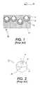
- FIG. 1depicts an enlarged section of rotating element sheet material 18 , including rotatable element 10 , enabling fluid 12 , cavity 14 , and substrate 16 . Observer 28 is also shown.
- FIG. 1depicts a spherically shaped rotatable element and cavity, many other shapes will work and are consistent with the present invention.
- the thickness of substrate 16may be of the order of hundreds of microns, and the dimensions of rotatable element 10 and cavity 14 may be of the order of 10 to 100 microns.
- substrate 16is an elastomer material, such as silicone rubber, that accommodates both enabling fluid 12 and the class of rotatable elements within a cavity or cavities disposed throughout substrate 16 .
- the cavity or cavitiescontain both enabling fluid 12 and the class of rotatable elements such that rotatable element 10 is in contact with enabling fluid 12 and at least one translational degree of freedom of rotatable element 10 is restricted.
- the contact between enabling fluid 12 and rotatable element 10breaks a symmetry of rotatable element 10 and allows rotatable element 10 to be addressed.
- the state of broken symmetry of rotatable element 10can be the establishment of an electric dipole about an axis of rotation.
- an electric dipolecan be established on a rotatable element in a dielectric liquid by the suitable choice of coatings applied to opposing surfaces of the rotatable element.
- rotating element sheet materialas “reusable electric paper” is due to that fact that the rotatable elements are typically given a second broken symmetry, a multivalued aspect, correlated with the addressing polarity discussed above. That is, the above mentioned coatings may be chosen so as to respond to incident electromagnetic energy in distinguishable ways.
- the aspect of rotatable element 10 to observer 28 favorably situatedcan be controlled by an applied vector field.
- rotatable element 10may comprise a black polyethylene generally spherical body with titanium oxide sputtered on one hemisphere, where the titanium oxide provides a light-colored aspect in one orientation.
- a rotatable element in a transparent dielectric liquidwill exhibit the desired addressing polarity as well as the desired aspect.
- a multivalued aspect in its simplest formis a two-valued aspect.
- a rotatable element with a two-valued aspectcan be referred to as a bichromal rotatable element.
- Such a rotatable elementis generally fabricated by the union of two layers of material as described in U.S. Pat. No. 5,262,098, herein incorporated by reference.
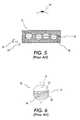
- FIGS. 2-5depict rotatable element 10 with a two-valued aspect and an exemplary system that use such rotatable elements from the prior art.
- rotatable element 10is composed of first layer 20 and second layer 22 and is, by way of example again, a generally spherical body.
- the surface of first layer 20has first coating 91 at a first Zeta potential
- the surface of second layer 22has second coating 93 at a second Zeta potential.
- First coating 91 and second coating 93are chosen such that, when in contact with a dielectric fluid (not shown), first coating 91 has a net positive electric charge with respect to second coating 93 . This is depicted in FIG. 2 by the “+” and “ ⁇ ” symbols respectively.
- first coating 91 and the surface of first layer 20is non-white-colored, indicated in FIG. 2 by hatching, and the combination of second coating 93 and the surface of second layer 22 is white-colored.
- first layer 20 and first coating 91may be the same.
- second layer 22 and second coating 93may be the same.
- FIG. 3depicts no-field set 30 .
- No-field set 30is a subset of randomly oriented rotatable elements in the vicinity of vector field 24 when vector field 24 has zero magnitude.
- Vector field 24is an electric field.
- No-field set 30thus, contains rotatable elements with arbitrary orientations with respect to each other. Therefore, observer 28 in the case of no-field set 30 registers views of the combination of second coating 93 and the surface of second layer 22 , and first coating 91 and the surface of first layer 20 (as depicted in FIG. 2) in an unordered sequence.
- Infralayer 26forms the backdrop of aspect 34 .
- Infralayer 26can consist of any type of material, including but not limited to other rotatable elements, or some material that presents a given aspect to observer 28 .
- FIGS. 4 and 5depict first aspect set 32 .
- First aspect set 32is a subset of rotatable elements in the vicinity of vector field 24 when the magnitude of vector field 24 is nonzero and has the orientation indicated by arrow 25 .
- all of the rotatable elementsorient themselves with respect to arrow 25 due to the electrostatic dipole present on each rotatable element 10 .
- observer 28 in the case of first aspect set 32registers a view of a set of rotatable elements ordered with the non-white-colored side up (the combination of first coating 91 and the surface of first layer 20 as depicted in FIG. 2 ).
- infralayer 26forms the backdrop of the aspect.
- FIG. 4is a side view indicating the relative positions of observer 28 , first aspect set 32 , and infralayer 26 .
- FIG. 5is an alternate view of first aspect set 32 from a top perspective. In FIG. 5, the symbol ⁇ indicates an arrow directed out of the plane of the figure.
- first aspect set 32will maintain its aspect after applied vector field 24 is removed, in part due to the energy associated with the attraction between rotatable element 10 and the substrate structure, as, for example, cavity walls (not shown). This energy contributes, in part, to the switching characteristics and the memory capability of rotating element sheet material 18 , as disclosed in U.S. Pat. No. 4,126,854, hereinabove incorporated by reference, and discussed in more detail below.
- a rotatable element with multivalued aspectis generally fabricated as disclosed in U.S. Pat. No. 5,919,409, herein incorporated by reference.
- An exemplary rotatable element 10 with multivalued aspect of the prior artis depicted in FIG. 6 .
- Rotatable element 10 in FIG. 6is composed of first layer 36 , second layer 37 and third layer 38 .
- the surface of third layer 38has third coating 95 at a first Zeta potential
- the surface of first layer 36has first coating 94 at a second Zeta potential such that third coating 95 has a net positive charge, “+,” with respect to first coating 94 when rotatable element 10 is in contact with a dielectric fluid (not shown).
- First layer 36 , first coating 94 , third layer 38 , and third coating 95may be chosen to be transparent to visible light and second layer 37 may be chosen to be opaque or transparent-colored to visible light, such that the rotatable element acts as a “light-valve,” as disclosed, for example, in U.S. Pat. No. 5,767,826, herein incorporated by reference, and U.S. Pat. No. 5,737,115, herein incorporated by reference.
- the material associated with first layer 36 and first coating 94may be the same.
- the material associated with third layer 38 and third coating 95may be the same.
- Rotatable elements with multivalued aspectare generally utilized in rotating element sheet material that use canted vector fields for addressing.
- a canted vector fieldis a field whose orientation vector in the vicinity of a subset of rotatable elements can be set so as to point in any direction in three-dimensional space.
- U.S. Pat. No. 5,717,545herein incorporated by reference, discloses the use of canted vector fields in order to address rotatable elements.
- the use of canted vector fields with rotating element sheet materialallows complete freedom in addressing the orientation of a subset of rotatable elements, where the rotatable elements have the addressing polarity discussed above.
- no-field set and first aspect set discussed above in FIGS. 3-5can form the elements of a pixel, where vector field 24 can be manipulated on a pixel by pixel basis using an addressing scheme as discussed, for example, in U.S. Pat. No. 5,717,515, hereinabove incorporated by reference.
- a useful property of rotating element sheet materialis the ability to maintain a given aspect after applied vector field 24 for addressing is removed. This ability contributes, in part, to the switching characteristics and the memory capability of rotating element sheet material 18 , as disclosed in U.S. Pat. No. 4,126,854, hereinabove incorporated by reference. This will be referred to as aspect stability.
- the mechanism for aspect stability in the above embodimentsis generally the energy associated with the attraction between the rotatable elements and the containment structure, or “work function.”
- a host of factorsinfluence the magnitude of the energy associated with the work function including, but not limited to: surface tension of enabling fluid in contact with rotatable elements; the relative specific gravity of the rotatable elements to the enabling fluid; magnitude of charge on rotatable elements in contact with containment structure; relative electronic permittivity of enabling fluid and containment structure; “stickiness” of containment structure; and other residual fields that may be present.
- the applied vector field for addressingmust be strong enough to overcome the work function in order to cause an orientation change; furthermore, the work function must be strong enough to maintain this aspect in the absence of an applied vector field for addressing.
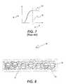
- FIG. 7depicts an exemplary diagram of number 54 , N, of rotatable elements that change orientation as a function of applied vector field 24 , V of the prior art.
- the work function 52 , V wcorresponds to the value of applied vector field 24 when the number 54 of rotatable elements that change orientation has reached the saturation level 56 , N s , corresponding to the orientation change of all rotatable elements 10 .
- the substrate of rotating element sheet materialis generally an elastomer material such as silicone rubber. Because of the expense of silicone rubber, the substrate is currently the most expensive component of rotating element sheet material. Thus, in large-area-display applications of rotating element sheet material, the cost of the substrate is the primary impediment.
- Other qualities of rotating element sheet materialare ideally suited to large-area-display applications. Such qualities include: lack of sensitivity to uniform thickness, low power requirements, and a wide viewing angle.
- rotating element sheet materialcomprises a fibrous matrix and a plurality of rotatable elements, where the plurality of rotatable elements are disposed within the fibrous matrix and in contact with an enabling fluid.
- rotating element sheet materialcomprises a fibrous matrix, a plurality of micro-capsules, and a plurality of rotatable elements, where each of the plurality of micro-capsules contain a subset of the plurality of rotatable elements and an enabling fluid. Furthermore, an additional supporting material may be interstitially contained in the fibrous matrix.
- the methodcomprises dispersing a plurality of rotatable elements into pulp slurry, drying and pressing thin layers of the pulp slurry into a fibrous matrix where the plurality of rotatable elements are interstitially contained, and infusing the fibrous matrix with an enabling fluid.
- the methodcomprises encapsulating a plurality of rotatable elements and enabling fluid into a plurality of micro-capsules, dispersing the plurality of micro-capsules into pulp slurry, drying and pressing thin layers of the pulp slurry into a fibrous matrix where the plurality of micro-capsules are interstitially contained. Furthermore, an additional supporting material may be introduced to the interstitial regions of the fibrous matrix.
- the methodcomprises pressing thin layers of pulp slurry into a fibrous matrix sheet, embossing cavities of size suitable to contain, preferably, single rotatable elements onto the surface of the fibrous matrix sheet using a mechanical embossing tool incorporating heat and pressure as needed, and subsequently drying the fibrous matrix sheet.
- the rotatable elementsare introduced to the embossed cavities by any conventional means known in the art, the fibrous matrix sheet is infused with enabling fluid, and the embossed cavities are sealed by laminating a second fibrous matrix sheet over the embossed fibrous matrix sheet.
- the embossed cavitiesare sealed by applying windowing material, such as glass or plastic sheets, to the embossed fibrous matrix sheet containing the rotatable elements in the embossed cavities.
- windowing materialsuch as glass or plastic sheets
- the embossed cavitiescan be introduced into dried fibrous matrix sheets using heat and pressure as required, and subsequently introducing the rotatable elements by any conventional means known in the art.
- the methodcomprises pressing thin layers of pulp slurry into a fibrous matrix sheet, embossing cavities of size suitable to contain, preferably, single micro-capsules containing one or more rotatable elements and enabling fluid, onto the surface of the fibrous matrix sheet using a mechanical embossing tool incorporating heat and pressure as needed, and subsequently drying the fibrous matrix sheet.
- embossing cavitiesof size suitable to contain, preferably, single micro-capsules containing one or more rotatable elements and enabling fluid, onto the surface of the fibrous matrix sheet using a mechanical embossing tool incorporating heat and pressure as needed, and subsequently drying the fibrous matrix sheet.
- the micro-capsulesare introduced to the embossed cavities by any conventional means known in the art, and the embossed cavities are sealed by laminating a second fibrous matrix sheet over the embossed fibrous matrix sheet.
- the embossed cavitiesare sealed by applying windowing material, such as glass or plastic sheets, to the embossed fibrous matrix sheet containing the micro-capsules in the embossed cavities.
- windowing materialsuch as glass or plastic sheets
- the embossed cavitiescan be introduced into dried fibrous matrix sheets using heat and pressure as required, and subsequently introducing the micro-capsules by any conventional means known in the art.
- an additional supporting materialmay be introduced to the interstitial regions of the fibrous matrix.
- the methodcomprises weaving a fibrous matrix sheet using a loom or other method of rapidly creating a fabric that enables placement of fibers in preferred patterns, where the preferred pattern in this embodiment defines preferred interstitial regions.
- Rotatable elementsare subsequently introduced to the preferred interstitial regions of the fibrous matrix sheet by any conventional means known in the art, the fibrous matrix sheet is infused with enabling fluid, and further laminated by another sheet or windowing material, as previously described.
- the plurality of rotatable elementsmay be placed in a preferred spatial configuration with respect to one another and a plurality of fibers or fibrous material introduced, by electrostatic or other means, to randomly encapsulate the rotatable elements.
- the plurality of fibers or fibrous materialthus arranged constitutes the desired fibrous matrix.
- the fibrous matrixis then infused with enabling fluid, and further laminated by another sheet or windowing material, as previously described.
- the methodcomprises weaving a fibrous matrix sheet using a loom or other method of rapidly creating a fabric that enables placement of fibers in preferred patterns, where the preferred pattern in this embodiment defines preferred interstitial regions.
- Micro-capsules containing one or more rotatable elements and enabling fluidare subsequently introduced to the preferred interstitial regions of the fibrous matrix sheet by any conventional means known in the art and the fibrous matrix sheet is laminated by another sheet or windowing material, as previously described.
- the plurality of micro-capsulesmay be placed in a preferred spatial configuration with respect to one another and a plurality of fibers or fibrous material introduced, by electrostatic or other means, to randomly encapsulate the micro-capsules.
- the plurality of fibers or fibrous materialthus arranged constitutes the desired fibrous matrix.
- the fibrous matrixis then laminated by another sheet or windowing material, as previously described.
- an additional supporting materialmay be introduced to the interstitial regions of the fibrous matrix.
- FIG. 1depicts an exemplary subsection of rotating element sheet material of the prior art.
- FIG. 2depicts an exemplary rotatable element of the prior art with a two-valued aspect.
- FIG. 3depicts an exemplary system of the prior art that uses rotatable elements with two-valued aspects of the prior art where the rotatable elements are randomly oriented in the presence of an addressing vector field with zero magnitude.
- FIG. 4depicts the exemplary system of FIG. 3 in the presence of a non-zero addressing vector field.
- FIG. 5depicts an alternate view of the exemplary system of FIG. 4 .
- FIG. 6depicts an exemplary rotatable element of the prior art with a multivalued aspect.
- FIG. 7depicts an exemplary graph of the number of rotatable elements that change orientation as a function of applied vector field of the prior art, displaying work function and saturation number
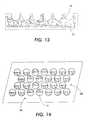
- FIG. 8depicts a fibrous matrix as an exemplary generalized containment structure consistent with the first embodiment of the present invention.
- FIG. 9depicts the exemplary generalized containment structure of FIG. 8 including first overlay, second overlay, and an exemplary addressor.
- FIG. 10depicts the system of FIG. 9 and an enabling fluid where the relative refractive index of the enabling fluid and the fibrous matrix is unity, or near unity.
- FIG. 11depicts a fibrous matrix structure supporting micro-capsules as an exemplary generalized containment structure consistent with the second embodiment of the present invention.
- FIG. 12depicts a fibrous matrix structure supporting micro-capsules and an additional supporting material, where the relative refractive index of the additional supporting material and the fibrous matrix structure is unity, or near unity.
- FIG. 13depicts an exemplary cross section view of an embossed fibrous matrix consistent with the third and fourth embodiments of a method for assembling rotating element sheet material of the present invention.
- FIG. 14depicts rotatable elements in an exemplary preferred spatial configuration prior to “flocking,” consistent with the fifth and sixth embodiments of a method for assembling rotating element sheet material of the present invention.
- FIG. 15depicts the rotatable elements of FIG. 14 and the encapsulating fibrous matrix formed by “flocking” consistent with the present invention.
- the present inventionrelates to rotating element sheet material with a generalized containment structure and methods of fabricating such rotating element sheet material.
- aspectsrefers to a common response to incident electromagnetic energy of interest. For example, if the incident electromagnetic energy of interest lies in the visible spectrum, then a first aspect can correspond to a black appearance, and a second aspect can correspond to a white appearance. If the incident electromagnetic energy of interest lies in the x-ray region, then a first aspect can correspond to the transmission of the x-ray energy, while a second aspect can correspond to the absorption of the x-ray energy.
- the “common response”can comprise any of the phenomena of absorption, reflection, polarization, transmission, fluorescence, or any combination thereof.
- observerrefers to a human perceiver, or to a human perceiver in conjunction with an apparatus sensitive to the electromagnetic energy of interest. If the electromagnetic energy of interest lies in the visible spectrum, then observer can refer to a human perceiver. If the electromagnetic energy of interest lies outside of the visible spectrum, then observer refers to an apparatus sensitive to the electromagnetic energy and capable of resolving the aspects of interest into human perceivable form.
- vector fieldrefers to a field whose amplitude in space is capable of having a magnitude and a direction.
- Vector fields of interest in the present inventioninclude electric fields, magnetic fields, electromagnetic fields, or gravitational fields.
- work functionrefers to the amount of energy necessary to overcome the attraction between a rotatable element and containment structure so as to enable a change of orientation.
- a host of factorsinfluence the magnitude of the energy associated with the work function including, but not limited to: surface tension of enabling fluid in contact with rotatable elements; the relative specific gravity of enabling fluid and rotatable element; magnitude of charge on rotatable element; relative electronic permittivity of enabling fluid and containment structure; “stickiness” of containment structure; and other residual vector fields that may be present.
- matrixrefers a to a structure in which elements of interest are enclosed or embedded in interstitial regions.
- fibrous matrixrefers to a structure resembling or nearly resembling intertwined fibers, and in which elements of interest are contained in interstitial regions.
- a structure comprising intertwined fibers where elements of interest are contained in interstitial regionsis a “fibrous matrix” structure.
- Elements of interestmay comprise, and are not limited to, rotatable elements, micro-capsules, enabling fluid, and solid-forming material such as epoxy.
- the “refractive index” of a materialis the ratio of the speed of the transmitted electromagnetic energy of interest in the material to the speed of the transmitted electromagnetic energy of interest in a vacuum.
- the electromagnetic energy of interestcan include, but is not limited to, the spectrum associated with visible light, x-rays, ultraviolet, or infrared radiation.
- degree of birefringencerefers to the relative difference between the refractive index of a material along a first axis and the refractive index of the same material along a second axis.
- transparentrefers to a material that is transmissive to electromagnetic energy of interest without significant deviation or absorption. It is not intended to be limited only to the spectrum of electromagnetic energy associated with visible light.
- windowing materialis material that is transparent to electromagnetic energy of interest and is rigid or nearly rigid, as plastic or glass.
- pulp slurryrefers to the mixture of cellulose material and liquid used to manufacture paper, as well as any equivalents as are conventionally known.
- FIG. 8A first embodiment of the present invention is depicted in FIG. 8 where fibrous matrix 60 is a plurality of paper fibers.
- fibrous matrix 60makes contact with and supports rotatable elements 10 .
- Also contained within fibrous matrix 60is enabling fluid 12 .
- the dotted lineindicates the boundary of fibrous matrix 60 and enabling fluid 12 , where, for example, some restraining means (not shown) keeps enabling fluid 12 within fibrous matrix 60 and around rotatable elements 10 .
- Fibrous matrix 60restricts the translational motion of rotatable elements 10 .
- Translational motion of rotational elements 10can occur as a result of any applied or stray vector field that may be present.
- An example of a stray vector field that is presentis the field associated with the gravitational force. In a large-area-display application, the force associated with the gravitational force will appreciably affect the appearance of the display.
- An example of an applied vector fieldis the field that is responsible for addressing the rot
- Fibrous matrix 60also restricts, but to a lesser extent, the rotational motion of rotatable elements 10 .
- Sufficiently strong vector fields for addressing, such as electric fields,can overcome the work function associated with the rotation of the rotatable elements 10 within fibrous matrix 60 .
- fibrous matrix 60is selected such that there is an appreciable work function associated with the rotation of rotatable elements 10 within fibrous matrix 60 .
- FIG. 9depicts the generalized containment structure substrate of FIG. 8, first overlay 70 , second overlay 72 , a representation of addressor 81 , and enabling fluid 12 .
- First overlay 70in a preferred embodiment of the present invention, is transparent or semi-transparent to the incident electromagnetic energy of interest, and, with second overlay 72 , may contain means for addressing rotatable elements 10 .
- First overlay 70 and second overlay 72may also serve to keep enabling fluid 12 within fibrous matrix 60 and around rotatable elements 10 .
- first overlay 70may be a glass surface
- second overlay 72may be a white-colored material such as plastic containing titanium dioxide pigment and glass with white paper backing, where the white-paper backing is not in contact with the region between first overlay 70 and second overlay 72 .
- first overlay 70 and second overlay 72may comprise any number of materials including polyester, glass or other windowing, transparent, or semi-transparent materials, as well as conductive materials in order to address rotatable elements 10 .
- Addressor 81 , first overlay 70 , and second overlay 72include any of the techniques or systems disclosed in: U.S. Pat. No.
- first overlay 70 and second overlay 72are preferably joined so as to envelope fibrous matrix 60 , enabling fluid 12 , and rotatable elements 10 .
- addressor 81first overlay 70 , and second overlay 72 include addressing systems as described above, and when first overlay 70 and second overlay 72 are so joined, the material connecting first overlay 70 to second overlay 72 is preferably nonconductive.
- V.B.Degree of birefringence in the fibrous matrix
- the relative refractive index of enabling fluid 12 and fibrous matrix 60is unity, or near unity. This renders fibrous matrix 60 transparent to the incident electromagnetic energy of interest. This transparency is depicted in FIG. 10 by showing rotatable elements only in the region between first overlay 70 and second overlay 72 .
- fibrous material for fibrous matrix 60when selecting fibrous material for fibrous matrix 60 in the current embodiment, it is desirable to use fibrous material that does not exhibit birefringence. Fibrous materials that exhibit birefringence will exhibit different values of refractive index from different observer 28 perspectives. In particular, a birefringent material exhibits not a single isotropic refractive index but two values. Since common fluids have a single refractive index it is impossible to match the refractive indices of such fibrous material to a single fluid. If the degree of birefringence is not too great, as with cellulose material, an acceptable trade-off may be found for some applications, due to the inexpensive nature of cellulose material. This is discussed more below.
- Polyester materialsin general, tend to exhibit a high degree of birefringence.
- cellulose materialstend to exhibit a significantly lower degree of birefringence, with typical values for the refractive index along different crystal axes of 1.618 and 1.544.
- acrylic materials and cellulose acetate materialsexhibit a very low degree of birefringence.
- Cellulose acetate materialhas effectively a single refractive index value of 1.475 and becomes essentially invisible when immersed in mineral oil.
- birefringenceis a property associated with the degree of crystallinity of the polymer, it tends to disappear with a loss in crystal properties.
- Polymerstend to be crystalline if they are comprised of equal sized molecules and to become amorphous as the range of molecular sizes becomes large.
- crystalline polyethylenecan have refractive indices of 1.520 and 1.582 but amorphous polyethylene, with a broad range of molecular sizes, will typically have a single refractive index of 1.49.
- fibrous material composed of many polymer fiberscan be used when the polymer fibers are caused to have amorphous properties.
- an enabling fluid with any desired value of refractive indexmay be obtained by mixing together in the proper proportion an enabling fluid of higher refractive index with an enabling fluid of lower refractive index.
- enabling fluids with refractive indices that closely match the refractive index of any transparent materialare easily obtained.
- a fibrous matrixthat comprises any of cellulose acetate fibers, borosilicate glass, and amorphous polyethylene
- a fibrous matrixmay comprise any such material and structure consistent with the present invention.
- FIG. 11depicts fibrous matrix 60 , micro-capsules 75 , rotatable elements 10 , and enabling fluid 12 .
- FIG. 11depicts micro-capsules 75 that are spherical in shape and that contain only one rotatable element per micro-capsule, one skilled in the art will appreciate that micro-capsules 75 may be any convenient shape or structure, and may contain more than one rotatable element 10 .
- Micro-capsules 75are made from material such as gelatin and are hollow within in order to accommodate rotatable elements 10 and enabling fluid 12 .
- the work function associated with the rotational motion of rotatable elements 10 within micro-capsules 75is a function of the properties of micro-capsules 75 , enabling fluid 12 , and rotatable elements 10 .
- the work function in this embodiment of the present inventionwill not be a function of the properties of fibrous matrix 60 . This can be advantageous when the material ideally suited to function as fibrous matrix 60 has properties that are not favorable to a suitable work function, or when there are problems associated with containing enabling fluid 12 within fibrous matrix 60 .
- the fluid that is in the interstitial region of fibrous matrix 60may be selected to be a solid-forming material, such as epoxy, and that hardens to a refractive index equal to that of fibrous matrix 60 . This is depicted in FIG. 12 .
- Fibrous matrix 60then performs the useful function of strengthening the resultant sheet and providing a low cost structure to maintain the relative positions of the plurality of micro-capsules 75 until the hardening of interstitial fluid 65 occurs.
- Rotatable elements 10are manufactured by any convenient means.
- rotatable elements 10are mixed in with paper pulp slurry containing fibers that exhibit a low degree of birefringence.
- Methods of incorporating micron-sized objects into paperhave been previously disclosed, for example, in U.S. Pat. No. 3,293,114, relating to paper with increased stiffness and caliper, in U.S. Pat. No. 4,046,404, relating to carbonless copy paper, and in U.S. Pat. No. 5,125,996, relating to a relief-imaging paper, all of which are herein incorporated by reference.
- the pulp slurryis processed into paper by any convenient means known in the art. As the water leaves the pulp slurry, the cellulose fibers will tightly enmesh rotatable elements 10 and form fibrous matrix 60 containing rotatable elements 10 . This is subsequently dried. As enabling fluid 12 is later infused into fibrous matrix 60 , there will be a slight swelling of the space surrounding rotatable elements 10 , allowing rotational motion. To cause controlled stiction of rotational elements 10 , a few percent concentration of fibrous material that retains its springiness, but ideally has the same optical properties as the pulp fibers, may be added to the pulp slurry.
- rotatable elements 10are manufactured by any convenient means as described above, including, but not limited to those disclosed in U.S. Pat. No. 5,262,098 and U.S. Pat. No. 5,919,409, both hereinabove incorporated by reference.
- Rotatable elements 10 and enabling fluid 12are then contained within micro-capsules 75 .
- a preferred process of including rotatable elements 10 and enabling fluid 12 into micro-capsules 75includes that disclosed in U.S. Pat. No. 5,604,027, herein incorporated by reference.
- micro-capsules 75containing rotatable elements 10 and enabling fluid 12 , are dispersed into pulp slurry as described above.
- means for including micron-sized material into paperhas previously been disclosed in U.S. Pat. No. 3,293,114, U.S. Pat. No. 4,046,404, and U.S. Pat. No. 5,125,996, both hereinabove incorporated by reference, and described above.
- the fluid that is in the interstitial region of fibrous matrix 60may be selected to be a solid-forming material, such as epoxy, and that hardens to a refractive index equal to that of fibrous matrix 60 .
- Fibrous matrix 60then performs the useful function of strengthening the resultant sheet and providing a low cost structure to maintain the relative positions of the plurality of micro-capsules 75 until the hardening of the interstitial fluid occurs.
- a fluidmay be infused in the interstitial region of fibrous matrix 60 that is a solid-forming material, such as epoxy.
- the interstitial fluidis then hardened by any conventional means known in the art, such as heating.
- rotatable elements 10are manufactured by any convenient means, as above.
- Fibrous matrix 60is formed by pressing agglomerated dry fibers into the form of a sheet or other preferred shape using a mechanical embossing tool that both compresses the agglomerated dry fibers into sheet form and creates a plurality of pocket-shaped micro-cavities in the fibrous matrix 60 , using both heat and pressure.
- a mechanical embossing toolthat both compresses the agglomerated dry fibers into sheet form and creates a plurality of pocket-shaped micro-cavities in the fibrous matrix 60 , using both heat and pressure.
- FIG. 13depicts pocket-shaped micro-cavities 85 as generally spherical, one skilled in the art will appreciate that a variety of shapes are possible, including square, cylindrical, and others.
- the embossing temperaturewill be that of the softening point of the glass fibers.
- the cellulose acetateis first slightly moistened by acetone, and the embossing pressure will then force the cavity-forming fibers into contact with each other.
- the embossing temperaturewill remove the acetone and cause the fibers in contact with one another to be cemented together.
- Rotatable elements 10are then placed in pocket-shaped micro-cavities 85 by any conventional means known in the art, and pocket-shaped micro-cavities 85 are sealed by laminating a layer of fibrous material in sheet form over the surface of embossed fibrous matrix 60 .
- the open tops of pocket-shaped micro-cavities 85may be closed by applying embossed fibrous matrix 60 between first overlay 70 and second overlay 72 , where first overlay 70 and second overlay 72 are selected to serve as suitable containment windows.
- rotatable elements 10are manufactured by any convenient means as described above, including, but not limited to those disclosed in U.S. Pat. No. 5,262,098 and U.S. Pat. No. 5,919,409, both hereinabove incorporated by reference.
- Rotatable elements 10 and enabling fluid 12are then contained within micro-capsules 75 .
- a preferred process of including rotatable elements 10 and enabling fluid 12 into micro-capsules 75includes that disclosed in U.S. Pat. No. 5,604,027, hereinabove incorporated by reference.
- Fibrous matrix 60is formed by pressing the agglomerated dry fibers into the form of a sheet or other preferred shape using a mechanical embossing tool that both compresses the fibers into sheet form and creates a plurality of pocket-shaped micro-cavities in the fibrous matrix sheet, using both heat and pressure.
- a mechanical embossing toolthat both compresses the fibers into sheet form and creates a plurality of pocket-shaped micro-cavities in the fibrous matrix sheet, using both heat and pressure.
- FIG. 13depicts pocket-shaped micro-cavities 85 as generally spherical, one skilled in the art will appreciate that a variety of shapes are possible, including square, cylindrical, and others.
- the embossing temperaturewill be that of the softening point of the glass fibers.
- the cellulose acetateis first slightly moistened by acetone, and the embossing pressure will then force the cavity-forming fibers into contact with each other.
- the embossing temperaturewill remove the acetone and cause the fibers in contact with one another to be cemented together.
- Micro-capsules 75are then placed in pocket-shaped micro-cavities 85 by any conventional means known in the art, and pocket-shaped micro-cavities 85 are sealed by laminating a layer of fibrous material in sheet form over the surface of embossed fibrous matrix 60 .
- the open tops of pocket-shaped micro-cavities 85may be closed by applying embossed fibrous matrix 60 between first overlay 70 and second overlay 72 , where first overlay 70 and second overlay 72 are selected to serve as suitable containment windows.
- the fluid that is in the interstitial region of fibrous matrix 60may be selected to be a solid-forming material, such as epoxy, and that hardens to a refractive index equal to that of embossed fibrous matrix 60 .
- Embossed fibrous matrix 60then performs the useful function of strengthening the resultant sheet and providing a low cost structure to maintain the relative positions of the plurality of micro-capsules 75 until the hardening of the interstitial fluid occurs.
- a fluidmay be infused in the interstitial region of embossed fibrous matrix 60 that is a solid-forming material, such as epoxy.
- the interstitial fluidis then hardened by any conventional means known in the art, such as heating.
- a method for assembling rotating element sheet materialcomprises manufacturing rotatable elements 10 by any convenient means, as above.
- the methodthen includes weaving a fibrous matrix sheet that defines preferred interstitial regions using a loom or other method of assembling a fabric that enables placement of fibers in preferred patterns.
- the preferred interstitial regionfor example, may define a significantly larger-than-average cavity within the fibrous matrix sheet.
- the rotatable elementsare subsequently placed in the preferred interstitial regions by any conventional means known in the art, and the preferred interstitial regions sealed by a second fibrous matrix sheet or with windowing material, as previously described.
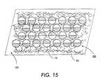
- the rotating elementsmay be placed on and lightly adhered to a surface in a preferred spatial configuration. This is depicted in FIG. 14, indicating surface 100 , rotatable element 10 , and preferred spatial configuration 105 .
- preferred spatial configuration 105may include any configuration.
- the fibrous materialmay then be placed around the rotatable elements to form fibrous matrix 60 with rotatable elements in the interstitial region. This is depicted in FIG. 15 indicating fibrous matrix 60 .
- the placement of the fibrous materialmay be done by the above described loom method, or it may be done by projecting the fibrous material in a random manner onto the surface and around the rotatable elements using electrostatic fields, air flow or other fibrous-material moving means.
- the electrostatic meansare known in the art as “flocking.” This encapsulation of rotatable elements 10 in fibrous matrix 60 then creates fibrous matrix 60 that fully contains rotatable elements 10 upon removal of the fibrous matrix 60 from surface 100 .
- a method for assembling rotating element sheet materialcomprises manufacturing rotatable elements 10 by any convenient means as described above, including, but not limited to those disclosed in U.S. Pat. No. 5,262,098 and U.S. Pat. No. 5,919,409, both hereinabove incorporated by reference.
- Rotatable elements 10 and enabling fluid 12are then contained within micro-capsules 75 .
- a preferred process of including rotatable elements 10 and enabling fluid 12 into micro-capsules 75includes that disclosed in U.S. Pat. No. 5,604,027, hereinabove incorporated by reference.
- the methodthen includes weaving a fibrous matrix sheet that defines preferred interstitial regions using a loom or other method of assembling a fabric that enables placement of fibers in preferred patterns.
- the preferred interstitial regionfor example, may define a significantly larger-than-average cavity within the fibrous matrix sheet.
- the micro-capsulesare subsequently placed in the preferred interstitial regions by any conventional means known in the art, and the preferred interstitial regions sealed by a second fibrous matrix sheet or with windowing material, as previously described.
- the micro-capsulesmay be placed on and lightly adhered to a surface in a preferred spatial configuration, as was described above with respect to rotatable elements.
- the fibrous materialmay then be placed around the micro-capsules to form fibrous matrix 60 with micro-capsules in the interstitial region.
- the placement of the fibrous materialmay be done by the above described loom method, or it may be done by projecting the fibrous material in a random manner onto the surface and around the micro-capsules using electrostatic fields, air flow or other fibrous-material moving means.
- the electrostatic meansare known in the art as “flocking.” This encapsulation of the micro-capsules in fibrous matrix 60 then creates a fibrous matrix that fully contains the micro-capsules upon removal of the fibrous matrix from the surface.
- the fluid that is in the interstitial region of fibrous matrix 60may be selected to be a solid-forming material, such as epoxy, and that hardens to a refractive index equal to that of fibrous matrix 60 .
- Fibrous matrix 60then performs the useful function of strengthening the resultant sheet and providing a low cost structure to maintain the relative positions of the plurality of micro-capsules 75 until the hardening of the interstitial fluid occurs.
- a fluidmay be infused in the interstitial region of fibrous matrix 60 that is a solid-forming material, such as epoxy.
- the interstitial fluidis then hardened by any conventional means known in the art, such as heating.
- fibrous matrix 60as composed of any of a plurality of paper fibers, cellulose acetate fibers, borosilicate glass, and amorphous polyethylene.
- any matrix structure with interstitial regions composed of material with a suitably low degree of birefringencewill function as well. Accordingly, the invention is not limited to the above-described embodiments, but instead is defined by the appended claims in light of their full scope of equivalents.
Landscapes
- Physics & Mathematics (AREA)
- General Physics & Mathematics (AREA)
- Engineering & Computer Science (AREA)
- Theoretical Computer Science (AREA)
- Electrochromic Elements, Electrophoresis, Or Variable Reflection Or Absorption Elements (AREA)
- Liquid Crystal (AREA)
- Paper (AREA)
Abstract
Description
Claims (39)
Priority Applications (2)
| Application Number | Priority Date | Filing Date | Title |
|---|---|---|---|
| US09/549,518US6498674B1 (en) | 2000-04-14 | 2000-04-14 | Rotating element sheet material with generalized containment structure |
| JP2001115956AJP2002023204A (en) | 2000-04-14 | 2001-04-13 | Rotary element sheet material having confining structure |
Applications Claiming Priority (1)
| Application Number | Priority Date | Filing Date | Title |
|---|---|---|---|
| US09/549,518US6498674B1 (en) | 2000-04-14 | 2000-04-14 | Rotating element sheet material with generalized containment structure |
Publications (1)
| Publication Number | Publication Date |
|---|---|
| US6498674B1true US6498674B1 (en) | 2002-12-24 |
Family
ID=24193338
Family Applications (1)
| Application Number | Title | Priority Date | Filing Date |
|---|---|---|---|
| US09/549,518Expired - LifetimeUS6498674B1 (en) | 2000-04-14 | 2000-04-14 | Rotating element sheet material with generalized containment structure |
Country Status (2)
| Country | Link |
|---|---|
| US (1) | US6498674B1 (en) |
| JP (1) | JP2002023204A (en) |
Cited By (25)
| Publication number | Priority date | Publication date | Assignee | Title |
|---|---|---|---|---|
| US20020131147A1 (en)* | 1998-08-27 | 2002-09-19 | Paolini Richard J. | Electrophoretic medium and process for the production thereof |
| US20020167481A1 (en)* | 2001-05-11 | 2002-11-14 | Wong Yoon Kean | Page flicking mechanism for electronic display devices that paginate content |
| US20030007239A1 (en)* | 2001-07-03 | 2003-01-09 | Fujitsu Limited | Colored rotating granular body and production method therefor, and display device thereof |
| US6657772B2 (en)* | 2001-07-09 | 2003-12-02 | E Ink Corporation | Electro-optic display and adhesive composition for use therein |
| US20040233508A1 (en)* | 2003-05-20 | 2004-11-25 | Kosc Tanya Z. | Electrically addressable optical devices using a system of composite layered flakes suspended in a fluid host to obtain angularly dependent optical effects |
| US6846377B2 (en) | 1999-12-17 | 2005-01-25 | Xerox Corporation | System and method for rotatable element assembly and laminate substrate assembly |
| US6847347B1 (en) | 2000-08-17 | 2005-01-25 | Xerox Corporation | Electromagnetophoretic display system and method |
| US6922276B2 (en) | 2002-12-23 | 2005-07-26 | E Ink Corporation | Flexible electro-optic displays |
| US7079305B2 (en) | 2001-03-19 | 2006-07-18 | E Ink Corporation | Electrophoretic medium and process for the production thereof |
| US20060248713A1 (en)* | 2005-05-04 | 2006-11-09 | Nokia Corporation | Method for manufacturing a laminate cover, laminate protective layer, and laminate electronic device having a reduced cost, manufacturing time, weight, and thickness |
| US20070146308A1 (en)* | 2005-12-23 | 2007-06-28 | Xerox Corporation | Addressable brush contact array |
| US7327511B2 (en) | 2004-03-23 | 2008-02-05 | E Ink Corporation | Light modulators |
| US20080100907A1 (en)* | 2006-10-10 | 2008-05-01 | Cbrite Inc. | Electro-optic display |
| US7411719B2 (en) | 1995-07-20 | 2008-08-12 | E Ink Corporation | Electrophoretic medium and process for the production thereof |
| US7492497B2 (en) | 2006-08-02 | 2009-02-17 | E Ink Corporation | Multi-layer light modulator |
| US20100035377A1 (en)* | 2006-12-22 | 2010-02-11 | Cbrite Inc. | Transfer Coating Method |
| US20100097687A1 (en)* | 2008-10-22 | 2010-04-22 | Cbrite Inc. | Rotating Element Transmissive Displays |
| US7713436B1 (en) | 2005-09-19 | 2010-05-11 | The University Of Rochester | Electrically actuatable doped polymer flakes and electrically addressable optical devices using suspensions of doped polymer flakes in a fluid host |
| US20100309543A1 (en)* | 2009-06-05 | 2010-12-09 | Cospheric Llc | Color Rotating Element Displays |
| US20110164497A1 (en)* | 2001-06-20 | 2011-07-07 | Juniper Networks, Inc. | Band control system for a digital subscriber network and band control method therefor |
| US7999787B2 (en) | 1995-07-20 | 2011-08-16 | E Ink Corporation | Methods for driving electrophoretic displays using dielectrophoretic forces |
| US8501272B2 (en) | 2006-12-22 | 2013-08-06 | Cospheric Llc | Hemispherical coating method for micro-elements |
| US20180299688A1 (en)* | 2015-10-08 | 2018-10-18 | Dai Nippon Printing Co., Ltd. | Particles, optical sheet, screen, display device, particle inspection device, particle manufacturing device, particle inspection method, particle manufacturing method, screen inspection method, and screen manufacturing method |
| US10331005B2 (en) | 2002-10-16 | 2019-06-25 | E Ink Corporation | Electrophoretic displays |
| US11250794B2 (en) | 2004-07-27 | 2022-02-15 | E Ink Corporation | Methods for driving electrophoretic displays using dielectrophoretic forces |
Citations (203)
| Publication number | Priority date | Publication date | Assignee | Title |
|---|---|---|---|---|
| US2326634A (en) | 1941-12-26 | 1943-08-10 | Minnesota Mining & Mfg | Reflex light reflector |
| US2354048A (en) | 1940-08-03 | 1944-07-18 | Minnesota Mining & Mfg | Flexible lenticular optical sheet |
| US2354049A (en) | 1944-01-19 | 1944-07-18 | Minnesota Mining & Mfg | Backless reflex light reflector |
| US2354018A (en) | 1940-08-03 | 1944-07-18 | Minnesota Mining & Mfg | Light reflector sheet |
| US2407680A (en) | 1945-03-02 | 1946-09-17 | Minnesota Mining & Mfg | Reflex light reflector |
| US2600963A (en) | 1948-04-08 | 1952-06-17 | Charles C Bland | Method and apparatus for forming glass beads |
| US2684788A (en) | 1950-02-09 | 1954-07-27 | Flex O Lite Mfg Corp | Bead dispenser |
| US2794301A (en) | 1953-01-29 | 1957-06-04 | Flex O Lite Mfg Corp | Production of free-flowing glass beads |
| US2950985A (en) | 1957-04-11 | 1960-08-30 | Flex O Lite Mfg Corp | Starch treated free flowing glass beads |
| US2965921A (en) | 1957-08-23 | 1960-12-27 | Flex O Lite Mfg Corp | Method and apparatus for producing glass beads from a free falling molten glass stream |
| US2980547A (en) | 1957-05-03 | 1961-04-18 | Flex O Lite Mfg Corp | High refractive index glass beads |
| US3036388A (en) | 1961-10-27 | 1962-05-29 | Clarence R Tate | Magnetic writing materials set |
| US3063388A (en) | 1960-05-12 | 1962-11-13 | Preco Inc | Load dividers for goods containing compartments, such as those of carriers |
| US3150947A (en) | 1961-07-13 | 1964-09-29 | Flex O Lite Mfg Corp | Method for production of glass beads by dispersion of molten glass |
| US3222204A (en) | 1960-04-20 | 1965-12-07 | Minnesota Mining & Mfg | Process of making beaded coatings and films from glass beads treated with oleophobic sizing agent |
| US3243273A (en) | 1957-08-12 | 1966-03-29 | Flex O Lite Mfg Corp | Method and apparatus for production of glass beads by dispersion of molten glass |
| US3310391A (en) | 1962-08-31 | 1967-03-21 | Flex O Lite Mfg Corp | Method of and apparatus for production of glass beads by use of a rotating wheel |
| US3406363A (en) | 1966-05-26 | 1968-10-15 | Clarence R. Tate | Multicolored micromagnets |
| US3594065A (en) | 1969-05-26 | 1971-07-20 | Alvin M Marks | Multiple iris raster |
| US3615993A (en) | 1967-07-14 | 1971-10-26 | Ibm | Magnetic ball production method |
| US3617333A (en) | 1968-10-30 | 1971-11-02 | Gen Steel Ind Inc | Process for flotation treatment of glass beads |
| US3648281A (en) | 1969-12-30 | 1972-03-07 | Ibm | Electrostatic display panel |
| US3795435A (en) | 1969-05-09 | 1974-03-05 | Swarovski & Co | Reflex light reflection sheet and method for its manufacture |
| US3915771A (en) | 1974-03-04 | 1975-10-28 | Minnesota Mining & Mfg | Pavement-marking tape |
| US3982334A (en) | 1970-03-27 | 1976-09-28 | Thalatta, Inc. | Compartmentalized micromagnet display device |
| US4001140A (en) | 1974-07-10 | 1977-01-04 | Ncr Corporation | Capsule manufacture |
| US4002022A (en) | 1974-10-01 | 1977-01-11 | Lopez C Guillermo | Electro-mechanical sign structure with alternating faces formed by several adjacent dihedral angles |
| US4082426A (en) | 1976-11-26 | 1978-04-04 | Minnesota Mining And Manufacturing Company | Retroreflective sheeting with retroreflective markings |
| USRE29742E (en) | 1973-11-05 | 1978-08-29 | Minnesota Mining And Manufacturing Company | Retroreflective protective helmet |
| US4117194A (en) | 1972-05-04 | 1978-09-26 | Rhone-Poulenc-Textile | Bicomponent filaments with a special cross-section |
| US4117192A (en) | 1976-02-17 | 1978-09-26 | Minnesota Mining And Manufacturing Company | Deformable retroreflective pavement-marking sheet material |
| US4126854A (en) | 1976-05-05 | 1978-11-21 | Xerox Corporation | Twisting ball panel display |
| US4143103A (en) | 1976-05-04 | 1979-03-06 | Xerox Corporation | Method of making a twisting ball panel display |
| US4143472A (en) | 1977-04-11 | 1979-03-13 | Pilot Man-Nen Hitsu Kabushiki Kaisha | Displaying magnetic panel and its display device |
| US4229732A (en) | 1978-12-11 | 1980-10-21 | International Business Machines Corporation | Micromechanical display logic and array |
| US4232084A (en) | 1978-01-25 | 1980-11-04 | Thalatta, Inc. | Sheets containing microencapsulated color-coded micromagnets |
| US4253909A (en) | 1976-04-12 | 1981-03-03 | Magnavox Government And Industrial Electronics Co. | Surface treating a portion of small articles |
| US4256677A (en) | 1976-04-12 | 1981-03-17 | Magnavox Government And Industrial Electronics Co. | Apparatus and method for making small spheres |
| US4261653A (en) | 1978-05-26 | 1981-04-14 | The Bendix Corporation | Light valve including dipolar particle construction and method of manufacture |
| US4268413A (en) | 1977-08-25 | 1981-05-19 | Wolfgang Dabisch | Bodies with reversibly variable temperature-dependent light absorbence |
| US4267946A (en) | 1979-10-01 | 1981-05-19 | Thatcher Gary G | Particulate matter dispensing device |
| US4273672A (en) | 1971-08-23 | 1981-06-16 | Champion International Corporation | Microencapsulation process |
| US4283438A (en) | 1979-12-26 | 1981-08-11 | Magnavox Government And Industrial Electronics Company | Method for individually encapsulating magnetic particles |
| US4288788A (en) | 1980-05-19 | 1981-09-08 | General Motors Corporation | Electrostatic alpha-numeric display |
| US4299880A (en) | 1979-11-15 | 1981-11-10 | Minnesota Mining And Manufacturing Company | Demand and timed renewing imaging media |
| US4367920A (en) | 1979-10-01 | 1983-01-11 | Minnesota Mining And Manufacturing Company | Retroflective sheeting |
| US4368952A (en) | 1979-12-11 | 1983-01-18 | Pilot Man-Nen-Hitsu Kabushiki Kaisha | Magnetic display panel using reversal magnetism |
| US4374889A (en) | 1981-12-07 | 1983-02-22 | Minnesota Mining And Manufacturing Company | Oil-repellent microvoid-imaging material |
| US4381616A (en) | 1981-09-11 | 1983-05-03 | Saxer Norman K | Internally illuminated rotatable pictorial menu display |
| US4402062A (en) | 1981-05-14 | 1983-08-30 | Batchelder J Samuel | Method and apparatus for dielectrophoretic storage and retrieval of information |
| US4411973A (en) | 1980-10-14 | 1983-10-25 | Eastman Kodak Company | Elements containing ordered wall arrays and processes for their fabrication |
| US4418098A (en) | 1980-09-02 | 1983-11-29 | Minnesota Mining & Manufacturing Company | Imaging media capable of displaying sharp indicia |
| US4418346A (en) | 1981-05-20 | 1983-11-29 | Batchelder J Samuel | Method and apparatus for providing a dielectrophoretic display of visual information |
| US4419383A (en) | 1979-12-26 | 1983-12-06 | Magnavox Government And Industrial Electronics Company | Method for individually encapsulating magnetic particles |
| US4438160A (en) | 1982-01-18 | 1984-03-20 | Sony Corporation | Method of making a rotary ball display device |
| US4441791A (en) | 1980-09-02 | 1984-04-10 | Texas Instruments Incorporated | Deformable mirror light modulator |
| US4457723A (en) | 1981-06-11 | 1984-07-03 | Thalatta, Inc. | Color changeable fabric |
| US4492435A (en) | 1982-07-02 | 1985-01-08 | Xerox Corporation | Multiple array full width electro mechanical modulator |
| US4500172A (en) | 1981-12-28 | 1985-02-19 | Hughes Aircraft Company | Two color liquid crystal light valve image projection system with single prepolarizer |
| US4511210A (en) | 1979-10-01 | 1985-04-16 | Minnesota Mining And Manufacturing Company | Retroreflective sheeting |
| US4532608A (en) | 1982-06-25 | 1985-07-30 | Wu Jiun Tsong | Memory device |
| US4569857A (en) | 1979-10-01 | 1986-02-11 | Minnesota Mining And Manufacturing Company | Retroreflective sheeting |
| US4592628A (en) | 1981-07-01 | 1986-06-03 | International Business Machines | Mirror array light valve |
| US4627689A (en) | 1983-12-08 | 1986-12-09 | University Of Pittsburgh | Crystalline colloidal narrow band radiation filter |
| US4632517A (en) | 1983-12-08 | 1986-12-30 | University Of Pittsburgh | Crystalline colloidal narrow band radiation filter |
| US4675476A (en) | 1984-10-11 | 1987-06-23 | Nec Corporation | Magnetophoresis type display and graphic input/output device using the same |
| US4678695A (en) | 1985-12-23 | 1987-07-07 | Minnesota Mining And Manufacturing Company | Encapsulated flattop retroreflective sheeting and method for producing the same |
| US4688900A (en) | 1984-03-19 | 1987-08-25 | Kent State University | Light modulating material comprising a liquid crystal dispersion in a plastic matrix |
| US4695528A (en) | 1980-07-16 | 1987-09-22 | Wolfgang Dabisch | Process for forming images using body with reversible fixable and temperature-variable light extinctions |
| US4710732A (en) | 1984-07-31 | 1987-12-01 | Texas Instruments Incorporated | Spatial light modulator and method |
| US4713295A (en) | 1985-03-28 | 1987-12-15 | Glaverbel | Method of modifying the wettability of glass beads, glass beads polymeric material incorporating such glass beads, and method of applying reflective markings to a surface |
| US4721649A (en) | 1985-05-08 | 1988-01-26 | Minnesota Mining And Manufacturing Company | Retroreflective sheeting |
| US4725494A (en) | 1982-09-02 | 1988-02-16 | Minnesota Mining And Manufacturing Co. | Retroreflective sheeting |
| US4729687A (en) | 1985-02-20 | 1988-03-08 | Minnesota Mining And Manufacturing Company | Imaging device |
| US4740266A (en) | 1985-07-01 | 1988-04-26 | Wu Jiun Tsong | Method of making memory devices |
| US4781789A (en) | 1985-07-01 | 1988-11-01 | Wu Jiun Tsong | Method of making memory devices |
| US4781790A (en) | 1985-07-01 | 1988-11-01 | Wu Jiun Tsong | Method of making memory devices |
| US4783236A (en) | 1985-07-01 | 1988-11-08 | Wu Jiun Tsong | Method of making memory devices |
| US4795528A (en) | 1985-07-01 | 1989-01-03 | Wu Jiun Tsong | Method of making memory devices |
| US4795243A (en) | 1983-06-10 | 1989-01-03 | Canon Kabushiki Kaisha | Granular member moving method and apparatus |
| US4810431A (en) | 1986-05-23 | 1989-03-07 | Ontario Research Foundation | Method of manufacturing plastic particles for a particle display |
| US4837071A (en) | 1986-11-25 | 1989-06-06 | Ricoh Company, Ltd. | Information display medium |
| US4877253A (en) | 1987-02-06 | 1989-10-31 | Minnesota Mining And Manufacturing Company | Reusable bingo card |
| US4890902A (en) | 1985-09-17 | 1990-01-02 | Kent State University | Liquid crystal light modulating materials with selectable viewing angles |
| US4919521A (en) | 1987-06-03 | 1990-04-24 | Nippon Sheet Glass Co., Ltd. | Electromagnetic device |
| US4931019A (en) | 1988-09-01 | 1990-06-05 | Pennwalt Corporation | Electrostatic image display apparatus |
| US4948232A (en) | 1983-12-16 | 1990-08-14 | Alf Lange | Device for the presentation of information with rollable plastic substrate |
| US4956619A (en) | 1988-02-19 | 1990-09-11 | Texas Instruments Incorporated | Spatial light modulator |
| US4991941A (en) | 1988-06-13 | 1991-02-12 | Kaiser Aerospace & Electronics Corporation | Method and apparatus for multi-color display |
| US4994204A (en) | 1988-11-04 | 1991-02-19 | Kent State University | Light modulating materials comprising a liquid crystal phase dispersed in a birefringent polymeric phase |
| US5039557A (en) | 1989-10-26 | 1991-08-13 | White Terrence H | Method for embedding reflective beads in thermoplastic pavement marking lines |
| US5066559A (en) | 1990-01-22 | 1991-11-19 | Minnesota Mining And Manufacturing Company | Liquid electrophotographic toner |
| US5075186A (en) | 1989-12-13 | 1991-12-24 | Xerox Corporation | Image-wise adhesion layers for printing |
| US5128203A (en) | 1988-02-19 | 1992-07-07 | Glaverbel | Marking comprising glass beads in a matrix |
| US5131736A (en) | 1990-05-30 | 1992-07-21 | The United States Of America As Represented By The Department Of Energy | Solid colloidal optical wavelength filter |
| US5151032A (en) | 1990-07-13 | 1992-09-29 | Kabushiki Kaisha Pilot | Magnetophoretic display panel |
| US5155607A (en) | 1990-03-16 | 1992-10-13 | Fuji Xerox Co., Ltd. | Optical modulation display device and display method using the same |
| US5157011A (en) | 1989-11-17 | 1992-10-20 | Oki Electric Industry Co., Ltd. | Thermoreversible recording medium, apparatus utilizing the same and method for fabricating the same |
| US5189658A (en) | 1989-06-30 | 1993-02-23 | Moses Klaus M | Device for recording information on an optical data carrier |
| US5219820A (en) | 1990-11-22 | 1993-06-15 | Ricoh Company, Ltd. | Reversible thermosensitive recording material and method of producing the same |
| US5223473A (en) | 1990-11-21 | 1993-06-29 | Xerox Corporation | Self-cleaning carbonless paper |
| US5226099A (en) | 1991-04-26 | 1993-07-06 | Texas Instruments Incorporated | Digital micromirror shutter device |
| US5233459A (en) | 1991-03-06 | 1993-08-03 | Massachusetts Institute Of Technology | Electric display device |
| US5249000A (en) | 1989-11-17 | 1993-09-28 | Oki Electric Industry Co., Ltd. | Thermoreversible recording medium, apparatus utilizing the same and method for fabricating the same |
| US5251048A (en) | 1992-05-18 | 1993-10-05 | Kent State University | Method and apparatus for electronic switching of a reflective color display |
| US5262374A (en) | 1989-11-17 | 1993-11-16 | Oki Electric Industry Co., Ltd. | Thermoreversible recording medium, apparatus utilizing the same and method for fabricating the same |
| US5262098A (en) | 1992-12-23 | 1993-11-16 | Xerox Corporation | Method and apparatus for fabricating bichromal balls for a twisting ball display |
| US5270872A (en) | 1989-07-20 | 1993-12-14 | The United States Of America As Represented By The Secretary Of The Air Force | Superconducting submicron filter |
| US5274460A (en) | 1990-07-04 | 1993-12-28 | Mitsubishi Denki Kabushiki Kaisha | Method of and apparatus for rewritable recording and erasing and rewritable recording film |
| US5290066A (en) | 1990-12-06 | 1994-03-01 | Mody Hemant K | Magnetic label and use thereof |
| US5315418A (en) | 1992-06-17 | 1994-05-24 | Xerox Corporation | Two path liquid crystal light valve color display with light coupling lens array disposed along the red-green light path |
| US5315776A (en) | 1992-10-07 | 1994-05-31 | Everbrite, Inc. | Multiple-display sign device |
| US5331454A (en) | 1990-11-13 | 1994-07-19 | Texas Instruments Incorporated | Low reset voltage process for DMD |
| US5344594A (en) | 1991-10-29 | 1994-09-06 | Xerox Corporation | Method for the fabrication of multicolored balls for a twisting ball display |
| US5351995A (en) | 1992-01-29 | 1994-10-04 | Apple Computer, Inc. | Double-sided, reversible electronic paper |
| US5354598A (en) | 1992-04-10 | 1994-10-11 | Minnesota Mining And Manufacturing Company | Article capable of displaying defined images |
| US5363222A (en) | 1989-06-07 | 1994-11-08 | Hughes Aircraft Company | Compact optical system for a single light valve full-color projector |
| US5383008A (en) | 1993-12-29 | 1995-01-17 | Xerox Corporation | Liquid ink electrostatic image development system |
| US5384067A (en) | 1991-05-02 | 1995-01-24 | Kent State University | Grey scale liquid crystal material |
| US5389945A (en) | 1989-11-08 | 1995-02-14 | Xerox Corporation | Writing system including paper-like digitally addressed media and addressing device therefor |
| US5389426A (en) | 1993-01-25 | 1995-02-14 | Minnesota Mining And Manufacturing Company | Article for use in forming a permanent image using a temporary marker |
| US5397503A (en) | 1991-04-18 | 1995-03-14 | Idemitsu Kosan Co., Ltd. | Liquid crystal composition and information display apparatus using the liquid crystal composition |
| US5411398A (en) | 1992-05-29 | 1995-05-02 | Japan Capsular Products, Inc. | Magnetic display system |
| US5416996A (en) | 1993-03-16 | 1995-05-23 | Clemens; Richard | Display apparatus |
| US5432526A (en) | 1970-12-28 | 1995-07-11 | Hyatt; Gilbert P. | Liquid crystal display having conductive cooling |
| US5432534A (en) | 1990-12-26 | 1995-07-11 | Ricoh Company, Ltd. | Reversible thermosensitive coloring composition, recording medium, recording method, and image display apparatus using the recording medium |
| US5459602A (en) | 1993-10-29 | 1995-10-17 | Texas Instruments | Micro-mechanical optical shutter |
| US5469020A (en) | 1994-03-14 | 1995-11-21 | Massachusetts Institute Of Technology | Flexible large screen display having multiple light emitting elements sandwiched between crossed electrodes |
| US5515075A (en) | 1991-06-28 | 1996-05-07 | Citizen Watch Co., Ltd | Multicolor display apparatus |
| US5535047A (en) | 1995-04-18 | 1996-07-09 | Texas Instruments Incorporated | Active yoke hidden hinge digital micromirror device |
| US5582700A (en) | 1995-10-16 | 1996-12-10 | Zikon Corporation | Electrophoretic display utilizing phase separation of liquids |
| US5604027A (en) | 1995-01-03 | 1997-02-18 | Xerox Corporation | Some uses of microencapsulation for electric paper |
| US5627562A (en) | 1993-11-26 | 1997-05-06 | Skodlar; Rafael | Magnetic display apparatus |
| US5659330A (en) | 1996-05-31 | 1997-08-19 | Xerox Corporation | Electrocapillary color display sheet |
| US5667924A (en) | 1996-02-14 | 1997-09-16 | Xerox Corporation | Superparamagnetic image character recognition compositions and processes of making and using |
| US5703671A (en) | 1995-08-28 | 1997-12-30 | Fuji Photo Film Co., Ltd. | Shading correction method, photographic printer and index print production apparatus |
| US5708525A (en) | 1995-12-15 | 1998-01-13 | Xerox Corporation | Applications of a transmissive twisting ball display |
| US5717283A (en) | 1996-01-03 | 1998-02-10 | Xerox Corporation | Display sheet with a plurality of hourglass shaped capsules containing marking means responsive to external fields |
| US5717515A (en) | 1995-12-15 | 1998-02-10 | Xerox Corporation | Canted electric fields for addressing a twisting ball display |
| US5717514A (en) | 1995-12-15 | 1998-02-10 | Xerox Corporation | Polychromal segmented balls for a twisting ball display |
| US5724064A (en) | 1995-12-27 | 1998-03-03 | Xerox Corporation | Computing system with an interactive display |
| US5723204A (en) | 1995-12-26 | 1998-03-03 | Xerox Corporation | Two-sided electrical paper |
| US5731792A (en) | 1996-05-06 | 1998-03-24 | Xerox Corporation | Electrocapillary color display sheet |
| US5737115A (en) | 1995-12-15 | 1998-04-07 | Xerox Corporation | Additive color tristate light valve twisting ball display |
| US5739946A (en) | 1995-09-21 | 1998-04-14 | Kabushiki Kaisha Toshiba | Display device |
| US5739801A (en) | 1995-12-15 | 1998-04-14 | Xerox Corporation | Multithreshold addressing of a twisting ball display |
| US5751268A (en) | 1995-12-15 | 1998-05-12 | Xerox Corporation | Pseudo-four color twisting ball display |
| US5754332A (en) | 1996-06-27 | 1998-05-19 | Xerox Corporation | Monolayer gyricon display |
| US5757345A (en) | 1996-05-06 | 1998-05-26 | Xerox Corportion | Electrocapillary color display sheet |
| US5760761A (en) | 1995-12-15 | 1998-06-02 | Xerox Corporation | Highlight color twisting ball display |
| US5767826A (en) | 1995-12-15 | 1998-06-16 | Xerox Corporation | Subtractive color twisting ball display |
| US5777782A (en) | 1996-12-24 | 1998-07-07 | Xerox Corporation | Auxiliary optics for a twisting ball display |
| US5808593A (en) | 1996-06-03 | 1998-09-15 | Xerox Corporation | Electrocapillary color display sheet |
| US5808783A (en) | 1996-06-27 | 1998-09-15 | Xerox Corporation | High reflectance gyricon display |
| US5815306A (en) | 1996-12-24 | 1998-09-29 | Xerox Corporation | "Eggcrate" substrate for a twisting ball display |
| US5821624A (en) | 1989-08-28 | 1998-10-13 | Lsi Logic Corporation | Semiconductor device assembly techniques using preformed planar structures |
| US5825529A (en) | 1996-06-27 | 1998-10-20 | Xerox Corporation | Gyricon display with no elastomer substrate |
| US5866284A (en) | 1997-05-28 | 1999-02-02 | Hewlett-Packard Company | Print method and apparatus for re-writable medium |
| US5869929A (en) | 1997-02-04 | 1999-02-09 | Idemitsu Kosan Co., Ltd. | Multicolor luminescent device |
| US5877844A (en) | 1995-06-13 | 1999-03-02 | Fuji Photo Film Co., Ltd. | Image exposure method using display panel |
| US5892497A (en) | 1995-12-15 | 1999-04-06 | Xerox Corporation | Additive color transmissive twisting ball display |
| US5893206A (en) | 1997-02-04 | 1999-04-13 | Eastman Kodak Company | Method for the formation and polarization of micromagnets |
| US5894367A (en) | 1996-09-13 | 1999-04-13 | Xerox Corporation | Twisting cylinder display using multiple chromatic values |
| US5900858A (en) | 1997-05-30 | 1999-05-04 | Xerox Corporation | Rotation mechanism for bichromal balls of a twisting ball display sheet based on contact potential charging |
| US5900192A (en) | 1998-01-09 | 1999-05-04 | Xerox Corporation | Method and apparatus for fabricating very small two-color balls for a twisting ball display |
| US5904790A (en) | 1997-10-30 | 1999-05-18 | Xerox Corporation | Method of manufacturing a twisting cylinder display using multiple chromatic values |
| US5906743A (en) | 1995-05-24 | 1999-05-25 | Kimberly Clark Worldwide, Inc. | Filter with zeolitic adsorbent attached to individual exposed surfaces of an electret-treated fibrous matrix |
| US5914805A (en) | 1996-06-27 | 1999-06-22 | Xerox Corporation | Gyricon display with interstitially packed particles |
| US5917646A (en) | 1996-12-24 | 1999-06-29 | Xerox Corporation | Rotatable lens transmissive twisting ball display |
| US5922268A (en) | 1997-10-30 | 1999-07-13 | Xerox Corporation | Method of manufacturing a twisting cylinder display using multiple chromatic values |
| US5930026A (en) | 1996-10-25 | 1999-07-27 | Massachusetts Institute Of Technology | Nonemissive displays and piezoelectric power supplies therefor |
| US5940054A (en) | 1996-06-11 | 1999-08-17 | Harris; Ellis D. | Triboelectric electret |
| US5956005A (en) | 1995-12-29 | 1999-09-21 | Xerox Corporation | Electrocapillary display sheet which utilizes an applied electric field to move a liquid inside the display sheet |
| US5961804A (en) | 1997-03-18 | 1999-10-05 | Massachusetts Institute Of Technology | Microencapsulated electrophoretic display |
| US5969472A (en) | 1997-12-03 | 1999-10-19 | Lockheed Martin Energy Research Corporation | Lighting system of encapsulated luminous material |
| US5974901A (en) | 1998-02-06 | 1999-11-02 | The Cleveland Clinic Foundation | Method for determining particle characteristics |
| US5976428A (en) | 1998-01-09 | 1999-11-02 | Xerox Corporation | Method and apparatus for controlling formation of two-color balls for a twisting ball display |
| US5975680A (en) | 1998-02-05 | 1999-11-02 | Eastman Kodak Company | Producing a non-emissive display having a plurality of pixels |
| US5982346A (en) | 1995-12-15 | 1999-11-09 | Xerox Corporation | Fabrication of a twisting ball display having two or more different kinds of balls |
| US5986629A (en) | 1996-10-02 | 1999-11-16 | Xerox Corporation | Electrostatic discharge indicator |
| US5989629A (en) | 1998-03-05 | 1999-11-23 | Xerox Corporation | Bichromal spheres |
| US6014116A (en) | 1996-08-28 | 2000-01-11 | Add-Vision, Inc. | Transportable electroluminescent display system |
| US6014247A (en) | 1998-06-05 | 2000-01-11 | Lear Automotive Dearborn, Inc. | Electronic ink dimming mirror |
| US6017584A (en) | 1995-07-20 | 2000-01-25 | E Ink Corporation | Multi-color electrophoretic displays and materials for making the same |
| US6034807A (en) | 1998-10-28 | 2000-03-07 | Memsolutions, Inc. | Bistable paper white direct view display |
| US6038059A (en) | 1998-10-16 | 2000-03-14 | Xerox Corporation | Additive color electric paper without registration or alignment of individual elements |
| US6054071A (en) | 1998-01-28 | 2000-04-25 | Xerox Corporation | Poled electrets for gyricon-based electric-paper displays |
| US6055091A (en) | 1996-06-27 | 2000-04-25 | Xerox Corporation | Twisting-cylinder display |
| US6054809A (en) | 1996-08-14 | 2000-04-25 | Add-Vision, Inc. | Electroluminescent lamp designs |
| US6067185A (en) | 1997-08-28 | 2000-05-23 | E Ink Corporation | Process for creating an encapsulated electrophoretic display |
| US6072621A (en) | 1998-02-06 | 2000-06-06 | Canon Kabushiki Kaisha | Colored ball display system |
| US6097531A (en) | 1998-11-25 | 2000-08-01 | Xerox Corporation | Method of making uniformly magnetized elements for a gyricon display |
| US6110538A (en) | 1998-11-25 | 2000-08-29 | Xerox Corporation | Method of making a gyricon display using magnetic latching |
| US6118419A (en) | 1996-10-02 | 2000-09-12 | Xerox Corporation | Random electrostatic discharge event indicator |
| US6120839A (en) | 1995-07-20 | 2000-09-19 | E Ink Corporation | Electro-osmotic displays and materials for making the same |
| US6120588A (en) | 1996-07-19 | 2000-09-19 | E Ink Corporation | Electronically addressable microencapsulated ink and display thereof |
| US6128124A (en) | 1998-10-16 | 2000-10-03 | Xerox Corporation | Additive color electric paper without registration or alignment of individual elements |
| US6137467A (en) | 1995-01-03 | 2000-10-24 | Xerox Corporation | Optically sensitive electric paper |
| US6147791A (en) | 1998-11-25 | 2000-11-14 | Xerox Corporation | Gyricon displays utilizing rotating elements and magnetic latching |
| US6162321A (en) | 1998-10-16 | 2000-12-19 | Xerox Corporation | Method for making additive color electric paper without registration or alignment of individual elements |
| US6174153B1 (en) | 1998-11-25 | 2001-01-16 | Xerox Corporation | Apparatus for making uniformly magnetized elements for a gyricon display |
| US6197228B1 (en) | 1998-11-25 | 2001-03-06 | Xerox Corporation | Method of making a gyricon display using magnetic latching |
| US6211998B1 (en) | 1998-11-25 | 2001-04-03 | Xerox Corporation | Magnetic unlatching and addressing of a gyricon display |
Family Cites Families (4)
| Publication number | Priority date | Publication date | Assignee | Title |
|---|---|---|---|---|
| MX9801552A (en)* | 1996-06-27 | 1998-05-31 | Xerox Corp | Twisting ball display. |
| JP3887958B2 (en)* | 1998-07-27 | 2007-02-28 | 富士ゼロックス株式会社 | Optical material and optical element |
| US6072619A (en)* | 1999-03-22 | 2000-06-06 | Visson Ip, Llc | Electro-optical light modulating device |
| US6440252B1 (en)* | 1999-12-17 | 2002-08-27 | Xerox Corporation | Method for rotatable element assembly |
- 2000
- 2000-04-14USUS09/549,518patent/US6498674B1/ennot_activeExpired - Lifetime
- 2001
- 2001-04-13JPJP2001115956Apatent/JP2002023204A/enactivePending
Patent Citations (212)
| Publication number | Priority date | Publication date | Assignee | Title |
|---|---|---|---|---|
| US2354048A (en) | 1940-08-03 | 1944-07-18 | Minnesota Mining & Mfg | Flexible lenticular optical sheet |
| US2354018A (en) | 1940-08-03 | 1944-07-18 | Minnesota Mining & Mfg | Light reflector sheet |
| US2326634A (en) | 1941-12-26 | 1943-08-10 | Minnesota Mining & Mfg | Reflex light reflector |
| US2354049A (en) | 1944-01-19 | 1944-07-18 | Minnesota Mining & Mfg | Backless reflex light reflector |
| US2407680A (en) | 1945-03-02 | 1946-09-17 | Minnesota Mining & Mfg | Reflex light reflector |
| US2600963A (en) | 1948-04-08 | 1952-06-17 | Charles C Bland | Method and apparatus for forming glass beads |
| US2684788A (en) | 1950-02-09 | 1954-07-27 | Flex O Lite Mfg Corp | Bead dispenser |
| US2794301A (en) | 1953-01-29 | 1957-06-04 | Flex O Lite Mfg Corp | Production of free-flowing glass beads |
| US2950985A (en) | 1957-04-11 | 1960-08-30 | Flex O Lite Mfg Corp | Starch treated free flowing glass beads |
| US2980547A (en) | 1957-05-03 | 1961-04-18 | Flex O Lite Mfg Corp | High refractive index glass beads |
| US3243273A (en) | 1957-08-12 | 1966-03-29 | Flex O Lite Mfg Corp | Method and apparatus for production of glass beads by dispersion of molten glass |
| US2965921A (en) | 1957-08-23 | 1960-12-27 | Flex O Lite Mfg Corp | Method and apparatus for producing glass beads from a free falling molten glass stream |
| US3222204A (en) | 1960-04-20 | 1965-12-07 | Minnesota Mining & Mfg | Process of making beaded coatings and films from glass beads treated with oleophobic sizing agent |
| US3063388A (en) | 1960-05-12 | 1962-11-13 | Preco Inc | Load dividers for goods containing compartments, such as those of carriers |
| US3150947A (en) | 1961-07-13 | 1964-09-29 | Flex O Lite Mfg Corp | Method for production of glass beads by dispersion of molten glass |
| US3036388A (en) | 1961-10-27 | 1962-05-29 | Clarence R Tate | Magnetic writing materials set |
| US3310391A (en) | 1962-08-31 | 1967-03-21 | Flex O Lite Mfg Corp | Method of and apparatus for production of glass beads by use of a rotating wheel |
| US3406363A (en) | 1966-05-26 | 1968-10-15 | Clarence R. Tate | Multicolored micromagnets |
| US3615993A (en) | 1967-07-14 | 1971-10-26 | Ibm | Magnetic ball production method |
| US3617333A (en) | 1968-10-30 | 1971-11-02 | Gen Steel Ind Inc | Process for flotation treatment of glass beads |
| US3795435A (en) | 1969-05-09 | 1974-03-05 | Swarovski & Co | Reflex light reflection sheet and method for its manufacture |
| US3594065A (en) | 1969-05-26 | 1971-07-20 | Alvin M Marks | Multiple iris raster |
| US3648281A (en) | 1969-12-30 | 1972-03-07 | Ibm | Electrostatic display panel |
| US3982334A (en) | 1970-03-27 | 1976-09-28 | Thalatta, Inc. | Compartmentalized micromagnet display device |
| US5432526A (en) | 1970-12-28 | 1995-07-11 | Hyatt; Gilbert P. | Liquid crystal display having conductive cooling |
| US4273672A (en) | 1971-08-23 | 1981-06-16 | Champion International Corporation | Microencapsulation process |
| US4117194A (en) | 1972-05-04 | 1978-09-26 | Rhone-Poulenc-Textile | Bicomponent filaments with a special cross-section |
| USRE29742E (en) | 1973-11-05 | 1978-08-29 | Minnesota Mining And Manufacturing Company | Retroreflective protective helmet |
| US3915771A (en) | 1974-03-04 | 1975-10-28 | Minnesota Mining & Mfg | Pavement-marking tape |
| US4001140A (en) | 1974-07-10 | 1977-01-04 | Ncr Corporation | Capsule manufacture |
| US4002022A (en) | 1974-10-01 | 1977-01-11 | Lopez C Guillermo | Electro-mechanical sign structure with alternating faces formed by several adjacent dihedral angles |
| US4117192A (en) | 1976-02-17 | 1978-09-26 | Minnesota Mining And Manufacturing Company | Deformable retroreflective pavement-marking sheet material |
| US4253909A (en) | 1976-04-12 | 1981-03-03 | Magnavox Government And Industrial Electronics Co. | Surface treating a portion of small articles |
| US4256677A (en) | 1976-04-12 | 1981-03-17 | Magnavox Government And Industrial Electronics Co. | Apparatus and method for making small spheres |
| US4143103A (en) | 1976-05-04 | 1979-03-06 | Xerox Corporation | Method of making a twisting ball panel display |
| US4126854A (en) | 1976-05-05 | 1978-11-21 | Xerox Corporation | Twisting ball panel display |
| US4082426A (en) | 1976-11-26 | 1978-04-04 | Minnesota Mining And Manufacturing Company | Retroreflective sheeting with retroreflective markings |
| US4143472A (en) | 1977-04-11 | 1979-03-13 | Pilot Man-Nen Hitsu Kabushiki Kaisha | Displaying magnetic panel and its display device |
| US4268413A (en) | 1977-08-25 | 1981-05-19 | Wolfgang Dabisch | Bodies with reversibly variable temperature-dependent light absorbence |
| US4232084A (en) | 1978-01-25 | 1980-11-04 | Thalatta, Inc. | Sheets containing microencapsulated color-coded micromagnets |
| US4261653A (en) | 1978-05-26 | 1981-04-14 | The Bendix Corporation | Light valve including dipolar particle construction and method of manufacture |
| US4229732A (en) | 1978-12-11 | 1980-10-21 | International Business Machines Corporation | Micromechanical display logic and array |
| US4267946A (en) | 1979-10-01 | 1981-05-19 | Thatcher Gary G | Particulate matter dispensing device |
| US4511210A (en) | 1979-10-01 | 1985-04-16 | Minnesota Mining And Manufacturing Company | Retroreflective sheeting |
| US4569857A (en) | 1979-10-01 | 1986-02-11 | Minnesota Mining And Manufacturing Company | Retroreflective sheeting |
| US4367920A (en) | 1979-10-01 | 1983-01-11 | Minnesota Mining And Manufacturing Company | Retroflective sheeting |
| US4299880A (en) | 1979-11-15 | 1981-11-10 | Minnesota Mining And Manufacturing Company | Demand and timed renewing imaging media |
| US4368952A (en) | 1979-12-11 | 1983-01-18 | Pilot Man-Nen-Hitsu Kabushiki Kaisha | Magnetic display panel using reversal magnetism |
| US4417543A (en) | 1979-12-26 | 1983-11-29 | Magnavox Government And Industrial Electronics Company | Apparatus for individually encapsulating magnetic particles |
| US4283438A (en) | 1979-12-26 | 1981-08-11 | Magnavox Government And Industrial Electronics Company | Method for individually encapsulating magnetic particles |
| US4419383A (en) | 1979-12-26 | 1983-12-06 | Magnavox Government And Industrial Electronics Company | Method for individually encapsulating magnetic particles |
| US4288788A (en) | 1980-05-19 | 1981-09-08 | General Motors Corporation | Electrostatic alpha-numeric display |
| US4695528A (en) | 1980-07-16 | 1987-09-22 | Wolfgang Dabisch | Process for forming images using body with reversible fixable and temperature-variable light extinctions |
| US4418098A (en) | 1980-09-02 | 1983-11-29 | Minnesota Mining & Manufacturing Company | Imaging media capable of displaying sharp indicia |
| US4441791A (en) | 1980-09-02 | 1984-04-10 | Texas Instruments Incorporated | Deformable mirror light modulator |
| US4411973A (en) | 1980-10-14 | 1983-10-25 | Eastman Kodak Company | Elements containing ordered wall arrays and processes for their fabrication |
| US4402062A (en) | 1981-05-14 | 1983-08-30 | Batchelder J Samuel | Method and apparatus for dielectrophoretic storage and retrieval of information |
| US4418346A (en) | 1981-05-20 | 1983-11-29 | Batchelder J Samuel | Method and apparatus for providing a dielectrophoretic display of visual information |
| US4457723A (en) | 1981-06-11 | 1984-07-03 | Thalatta, Inc. | Color changeable fabric |
| US4592628A (en) | 1981-07-01 | 1986-06-03 | International Business Machines | Mirror array light valve |
| US4381616A (en) | 1981-09-11 | 1983-05-03 | Saxer Norman K | Internally illuminated rotatable pictorial menu display |
| US4374889A (en) | 1981-12-07 | 1983-02-22 | Minnesota Mining And Manufacturing Company | Oil-repellent microvoid-imaging material |
| US4500172A (en) | 1981-12-28 | 1985-02-19 | Hughes Aircraft Company | Two color liquid crystal light valve image projection system with single prepolarizer |
| US4438160A (en) | 1982-01-18 | 1984-03-20 | Sony Corporation | Method of making a rotary ball display device |
| US4532608A (en) | 1982-06-25 | 1985-07-30 | Wu Jiun Tsong | Memory device |
| US4492435A (en) | 1982-07-02 | 1985-01-08 | Xerox Corporation | Multiple array full width electro mechanical modulator |
| US4725494A (en) | 1982-09-02 | 1988-02-16 | Minnesota Mining And Manufacturing Co. | Retroreflective sheeting |
| US4795243A (en) | 1983-06-10 | 1989-01-03 | Canon Kabushiki Kaisha | Granular member moving method and apparatus |
| US4627689A (en) | 1983-12-08 | 1986-12-09 | University Of Pittsburgh | Crystalline colloidal narrow band radiation filter |
| US4632517A (en) | 1983-12-08 | 1986-12-30 | University Of Pittsburgh | Crystalline colloidal narrow band radiation filter |
| US4948232A (en) | 1983-12-16 | 1990-08-14 | Alf Lange | Device for the presentation of information with rollable plastic substrate |
| US4688900A (en) | 1984-03-19 | 1987-08-25 | Kent State University | Light modulating material comprising a liquid crystal dispersion in a plastic matrix |
| US4710732A (en) | 1984-07-31 | 1987-12-01 | Texas Instruments Incorporated | Spatial light modulator and method |
| US4675476A (en) | 1984-10-11 | 1987-06-23 | Nec Corporation | Magnetophoresis type display and graphic input/output device using the same |
| US4729687A (en) | 1985-02-20 | 1988-03-08 | Minnesota Mining And Manufacturing Company | Imaging device |
| US4713295A (en) | 1985-03-28 | 1987-12-15 | Glaverbel | Method of modifying the wettability of glass beads, glass beads polymeric material incorporating such glass beads, and method of applying reflective markings to a surface |
| US4721649A (en) | 1985-05-08 | 1988-01-26 | Minnesota Mining And Manufacturing Company | Retroreflective sheeting |
| US4781789A (en) | 1985-07-01 | 1988-11-01 | Wu Jiun Tsong | Method of making memory devices |
| US4781790A (en) | 1985-07-01 | 1988-11-01 | Wu Jiun Tsong | Method of making memory devices |
| US4783236A (en) | 1985-07-01 | 1988-11-08 | Wu Jiun Tsong | Method of making memory devices |
| US4795528A (en) | 1985-07-01 | 1989-01-03 | Wu Jiun Tsong | Method of making memory devices |
| US4740266A (en) | 1985-07-01 | 1988-04-26 | Wu Jiun Tsong | Method of making memory devices |
| US4890902A (en) | 1985-09-17 | 1990-01-02 | Kent State University | Liquid crystal light modulating materials with selectable viewing angles |
| US4678695A (en) | 1985-12-23 | 1987-07-07 | Minnesota Mining And Manufacturing Company | Encapsulated flattop retroreflective sheeting and method for producing the same |
| US4810431A (en) | 1986-05-23 | 1989-03-07 | Ontario Research Foundation | Method of manufacturing plastic particles for a particle display |
| US4837071A (en) | 1986-11-25 | 1989-06-06 | Ricoh Company, Ltd. | Information display medium |
| US4877253A (en) | 1987-02-06 | 1989-10-31 | Minnesota Mining And Manufacturing Company | Reusable bingo card |
| US4919521A (en) | 1987-06-03 | 1990-04-24 | Nippon Sheet Glass Co., Ltd. | Electromagnetic device |
| US4956619A (en) | 1988-02-19 | 1990-09-11 | Texas Instruments Incorporated | Spatial light modulator |
| US5128203A (en) | 1988-02-19 | 1992-07-07 | Glaverbel | Marking comprising glass beads in a matrix |
| US4991941A (en) | 1988-06-13 | 1991-02-12 | Kaiser Aerospace & Electronics Corporation | Method and apparatus for multi-color display |
| US4931019A (en) | 1988-09-01 | 1990-06-05 | Pennwalt Corporation | Electrostatic image display apparatus |
| US4994204A (en) | 1988-11-04 | 1991-02-19 | Kent State University | Light modulating materials comprising a liquid crystal phase dispersed in a birefringent polymeric phase |
| US5363222A (en) | 1989-06-07 | 1994-11-08 | Hughes Aircraft Company | Compact optical system for a single light valve full-color projector |
| US5189658A (en) | 1989-06-30 | 1993-02-23 | Moses Klaus M | Device for recording information on an optical data carrier |
| US5270872A (en) | 1989-07-20 | 1993-12-14 | The United States Of America As Represented By The Secretary Of The Air Force | Superconducting submicron filter |
| US5821624A (en) | 1989-08-28 | 1998-10-13 | Lsi Logic Corporation | Semiconductor device assembly techniques using preformed planar structures |
| US5039557A (en) | 1989-10-26 | 1991-08-13 | White Terrence H | Method for embedding reflective beads in thermoplastic pavement marking lines |
| US5389945A (en) | 1989-11-08 | 1995-02-14 | Xerox Corporation | Writing system including paper-like digitally addressed media and addressing device therefor |
| US5262374A (en) | 1989-11-17 | 1993-11-16 | Oki Electric Industry Co., Ltd. | Thermoreversible recording medium, apparatus utilizing the same and method for fabricating the same |
| US5157011A (en) | 1989-11-17 | 1992-10-20 | Oki Electric Industry Co., Ltd. | Thermoreversible recording medium, apparatus utilizing the same and method for fabricating the same |
| US5249000A (en) | 1989-11-17 | 1993-09-28 | Oki Electric Industry Co., Ltd. | Thermoreversible recording medium, apparatus utilizing the same and method for fabricating the same |
| US5075186A (en) | 1989-12-13 | 1991-12-24 | Xerox Corporation | Image-wise adhesion layers for printing |
| US5066559A (en) | 1990-01-22 | 1991-11-19 | Minnesota Mining And Manufacturing Company | Liquid electrophotographic toner |
| US5155607A (en) | 1990-03-16 | 1992-10-13 | Fuji Xerox Co., Ltd. | Optical modulation display device and display method using the same |
| US5131736A (en) | 1990-05-30 | 1992-07-21 | The United States Of America As Represented By The Department Of Energy | Solid colloidal optical wavelength filter |
| US5274460A (en) | 1990-07-04 | 1993-12-28 | Mitsubishi Denki Kabushiki Kaisha | Method of and apparatus for rewritable recording and erasing and rewritable recording film |
| US5151032A (en) | 1990-07-13 | 1992-09-29 | Kabushiki Kaisha Pilot | Magnetophoretic display panel |
| US5331454A (en) | 1990-11-13 | 1994-07-19 | Texas Instruments Incorporated | Low reset voltage process for DMD |
| US5223473A (en) | 1990-11-21 | 1993-06-29 | Xerox Corporation | Self-cleaning carbonless paper |
| US5219820A (en) | 1990-11-22 | 1993-06-15 | Ricoh Company, Ltd. | Reversible thermosensitive recording material and method of producing the same |
| US5290066A (en) | 1990-12-06 | 1994-03-01 | Mody Hemant K | Magnetic label and use thereof |
| US5432534A (en) | 1990-12-26 | 1995-07-11 | Ricoh Company, Ltd. | Reversible thermosensitive coloring composition, recording medium, recording method, and image display apparatus using the recording medium |
| US5233459A (en) | 1991-03-06 | 1993-08-03 | Massachusetts Institute Of Technology | Electric display device |
| US5784189A (en) | 1991-03-06 | 1998-07-21 | Massachusetts Institute Of Technology | Spatial light modulator |
| US5397503A (en) | 1991-04-18 | 1995-03-14 | Idemitsu Kosan Co., Ltd. | Liquid crystal composition and information display apparatus using the liquid crystal composition |
| US5226099A (en) | 1991-04-26 | 1993-07-06 | Texas Instruments Incorporated | Digital micromirror shutter device |
| US5384067A (en) | 1991-05-02 | 1995-01-24 | Kent State University | Grey scale liquid crystal material |
| US5526016A (en) | 1991-06-28 | 1996-06-11 | Citizen Watch Co., Ltd. | Multicolor display apparatus |
| US5515075A (en) | 1991-06-28 | 1996-05-07 | Citizen Watch Co., Ltd | Multicolor display apparatus |
| US5344594A (en) | 1991-10-29 | 1994-09-06 | Xerox Corporation | Method for the fabrication of multicolored balls for a twisting ball display |
| US5351995A (en) | 1992-01-29 | 1994-10-04 | Apple Computer, Inc. | Double-sided, reversible electronic paper |
| US5354598A (en) | 1992-04-10 | 1994-10-11 | Minnesota Mining And Manufacturing Company | Article capable of displaying defined images |
| US5251048A (en) | 1992-05-18 | 1993-10-05 | Kent State University | Method and apparatus for electronic switching of a reflective color display |
| US5411398A (en) | 1992-05-29 | 1995-05-02 | Japan Capsular Products, Inc. | Magnetic display system |
| US5315418A (en) | 1992-06-17 | 1994-05-24 | Xerox Corporation | Two path liquid crystal light valve color display with light coupling lens array disposed along the red-green light path |
| US5315776A (en) | 1992-10-07 | 1994-05-31 | Everbrite, Inc. | Multiple-display sign device |
| US5262098A (en) | 1992-12-23 | 1993-11-16 | Xerox Corporation | Method and apparatus for fabricating bichromal balls for a twisting ball display |
| US5389426A (en) | 1993-01-25 | 1995-02-14 | Minnesota Mining And Manufacturing Company | Article for use in forming a permanent image using a temporary marker |
| US5416996A (en) | 1993-03-16 | 1995-05-23 | Clemens; Richard | Display apparatus |
| US5459602A (en) | 1993-10-29 | 1995-10-17 | Texas Instruments | Micro-mechanical optical shutter |
| US5627562A (en) | 1993-11-26 | 1997-05-06 | Skodlar; Rafael | Magnetic display apparatus |
| US5383008A (en) | 1993-12-29 | 1995-01-17 | Xerox Corporation | Liquid ink electrostatic image development system |
| US5469020A (en) | 1994-03-14 | 1995-11-21 | Massachusetts Institute Of Technology | Flexible large screen display having multiple light emitting elements sandwiched between crossed electrodes |
| US5604027A (en) | 1995-01-03 | 1997-02-18 | Xerox Corporation | Some uses of microencapsulation for electric paper |
| USRE37085E1 (en) | 1995-01-03 | 2001-03-06 | Xerox Corporation | Some uses of microencapsulation for electric paper |
| US6137467A (en) | 1995-01-03 | 2000-10-24 | Xerox Corporation | Optically sensitive electric paper |
| US5535047A (en) | 1995-04-18 | 1996-07-09 | Texas Instruments Incorporated | Active yoke hidden hinge digital micromirror device |
| US5906743A (en) | 1995-05-24 | 1999-05-25 | Kimberly Clark Worldwide, Inc. | Filter with zeolitic adsorbent attached to individual exposed surfaces of an electret-treated fibrous matrix |
| US5877844A (en) | 1995-06-13 | 1999-03-02 | Fuji Photo Film Co., Ltd. | Image exposure method using display panel |
| US6017584A (en) | 1995-07-20 | 2000-01-25 | E Ink Corporation | Multi-color electrophoretic displays and materials for making the same |
| US6120839A (en) | 1995-07-20 | 2000-09-19 | E Ink Corporation | Electro-osmotic displays and materials for making the same |
| US5703671A (en) | 1995-08-28 | 1997-12-30 | Fuji Photo Film Co., Ltd. | Shading correction method, photographic printer and index print production apparatus |
| US5828441A (en) | 1995-08-28 | 1998-10-27 | Fuji Photo Film Co., Ltd. | Shading correction method, photographic printer and index print production apparatus |
| US5739946A (en) | 1995-09-21 | 1998-04-14 | Kabushiki Kaisha Toshiba | Display device |
| US5582700A (en) | 1995-10-16 | 1996-12-10 | Zikon Corporation | Electrophoretic display utilizing phase separation of liquids |
| US5760761A (en) | 1995-12-15 | 1998-06-02 | Xerox Corporation | Highlight color twisting ball display |
| US5717515A (en) | 1995-12-15 | 1998-02-10 | Xerox Corporation | Canted electric fields for addressing a twisting ball display |
| US5751268A (en) | 1995-12-15 | 1998-05-12 | Xerox Corporation | Pseudo-four color twisting ball display |
| US5982346A (en) | 1995-12-15 | 1999-11-09 | Xerox Corporation | Fabrication of a twisting ball display having two or more different kinds of balls |
| US5737115A (en) | 1995-12-15 | 1998-04-07 | Xerox Corporation | Additive color tristate light valve twisting ball display |
| US5892497A (en) | 1995-12-15 | 1999-04-06 | Xerox Corporation | Additive color transmissive twisting ball display |
| US5767826A (en) | 1995-12-15 | 1998-06-16 | Xerox Corporation | Subtractive color twisting ball display |
| US5919409A (en) | 1995-12-15 | 1999-07-06 | Xerox Corporation | Method for fabricating polychromal segmented balls for a twisting ball display |
| US5708525A (en) | 1995-12-15 | 1998-01-13 | Xerox Corporation | Applications of a transmissive twisting ball display |
| US5717514A (en) | 1995-12-15 | 1998-02-10 | Xerox Corporation | Polychromal segmented balls for a twisting ball display |
| US5739801A (en) | 1995-12-15 | 1998-04-14 | Xerox Corporation | Multithreshold addressing of a twisting ball display |
| US5891479A (en) | 1995-12-15 | 1999-04-06 | Xerox Corporation | Apparatus for fabricating polychromal segmented balls for twisting ball display |
| US5723204A (en) | 1995-12-26 | 1998-03-03 | Xerox Corporation | Two-sided electrical paper |
| US5724064A (en) | 1995-12-27 | 1998-03-03 | Xerox Corporation | Computing system with an interactive display |
| US5956005A (en) | 1995-12-29 | 1999-09-21 | Xerox Corporation | Electrocapillary display sheet which utilizes an applied electric field to move a liquid inside the display sheet |
| US5717283A (en) | 1996-01-03 | 1998-02-10 | Xerox Corporation | Display sheet with a plurality of hourglass shaped capsules containing marking means responsive to external fields |
| US5667924A (en) | 1996-02-14 | 1997-09-16 | Xerox Corporation | Superparamagnetic image character recognition compositions and processes of making and using |
| US5757345A (en) | 1996-05-06 | 1998-05-26 | Xerox Corportion | Electrocapillary color display sheet |
| US5731792A (en) | 1996-05-06 | 1998-03-24 | Xerox Corporation | Electrocapillary color display sheet |
| US5659330A (en) | 1996-05-31 | 1997-08-19 | Xerox Corporation | Electrocapillary color display sheet |
| US5808593A (en) | 1996-06-03 | 1998-09-15 | Xerox Corporation | Electrocapillary color display sheet |
| US5940054A (en) | 1996-06-11 | 1999-08-17 | Harris; Ellis D. | Triboelectric electret |
| US5808783A (en) | 1996-06-27 | 1998-09-15 | Xerox Corporation | High reflectance gyricon display |
| US6055091A (en) | 1996-06-27 | 2000-04-25 | Xerox Corporation | Twisting-cylinder display |
| US5914805A (en) | 1996-06-27 | 1999-06-22 | Xerox Corporation | Gyricon display with interstitially packed particles |
| US5825529A (en) | 1996-06-27 | 1998-10-20 | Xerox Corporation | Gyricon display with no elastomer substrate |
| US5754332A (en) | 1996-06-27 | 1998-05-19 | Xerox Corporation | Monolayer gyricon display |
| US6120588A (en) | 1996-07-19 | 2000-09-19 | E Ink Corporation | Electronically addressable microencapsulated ink and display thereof |
| US6054809A (en) | 1996-08-14 | 2000-04-25 | Add-Vision, Inc. | Electroluminescent lamp designs |
| US6014116A (en) | 1996-08-28 | 2000-01-11 | Add-Vision, Inc. | Transportable electroluminescent display system |
| US5894367A (en) | 1996-09-13 | 1999-04-13 | Xerox Corporation | Twisting cylinder display using multiple chromatic values |
| US6118419A (en) | 1996-10-02 | 2000-09-12 | Xerox Corporation | Random electrostatic discharge event indicator |
| US5986629A (en) | 1996-10-02 | 1999-11-16 | Xerox Corporation | Electrostatic discharge indicator |
| US6130773A (en) | 1996-10-25 | 2000-10-10 | Massachusetts Institute Of Technology | Nonemissive displays and piezoelectric power supplies therefor |
| US5930026A (en) | 1996-10-25 | 1999-07-27 | Massachusetts Institute Of Technology | Nonemissive displays and piezoelectric power supplies therefor |
| US5917646A (en) | 1996-12-24 | 1999-06-29 | Xerox Corporation | Rotatable lens transmissive twisting ball display |
| US5777782A (en) | 1996-12-24 | 1998-07-07 | Xerox Corporation | Auxiliary optics for a twisting ball display |
| US5815306A (en) | 1996-12-24 | 1998-09-29 | Xerox Corporation | "Eggcrate" substrate for a twisting ball display |
| US5869929A (en) | 1997-02-04 | 1999-02-09 | Idemitsu Kosan Co., Ltd. | Multicolor luminescent device |
| US5893206A (en) | 1997-02-04 | 1999-04-13 | Eastman Kodak Company | Method for the formation and polarization of micromagnets |
| US5961804A (en) | 1997-03-18 | 1999-10-05 | Massachusetts Institute Of Technology | Microencapsulated electrophoretic display |
| US5866284A (en) | 1997-05-28 | 1999-02-02 | Hewlett-Packard Company | Print method and apparatus for re-writable medium |
| US5900858A (en) | 1997-05-30 | 1999-05-04 | Xerox Corporation | Rotation mechanism for bichromal balls of a twisting ball display sheet based on contact potential charging |
| US6067185A (en) | 1997-08-28 | 2000-05-23 | E Ink Corporation | Process for creating an encapsulated electrophoretic display |
| US5904790A (en) | 1997-10-30 | 1999-05-18 | Xerox Corporation | Method of manufacturing a twisting cylinder display using multiple chromatic values |
| US5922268A (en) | 1997-10-30 | 1999-07-13 | Xerox Corporation | Method of manufacturing a twisting cylinder display using multiple chromatic values |
| US5969472A (en) | 1997-12-03 | 1999-10-19 | Lockheed Martin Energy Research Corporation | Lighting system of encapsulated luminous material |
| US5976428A (en) | 1998-01-09 | 1999-11-02 | Xerox Corporation | Method and apparatus for controlling formation of two-color balls for a twisting ball display |
| US5900192A (en) | 1998-01-09 | 1999-05-04 | Xerox Corporation | Method and apparatus for fabricating very small two-color balls for a twisting ball display |
| US6054071A (en) | 1998-01-28 | 2000-04-25 | Xerox Corporation | Poled electrets for gyricon-based electric-paper displays |
| US5975680A (en) | 1998-02-05 | 1999-11-02 | Eastman Kodak Company | Producing a non-emissive display having a plurality of pixels |
| US6072621A (en) | 1998-02-06 | 2000-06-06 | Canon Kabushiki Kaisha | Colored ball display system |
| US5974901A (en) | 1998-02-06 | 1999-11-02 | The Cleveland Clinic Foundation | Method for determining particle characteristics |
| US5989629A (en) | 1998-03-05 | 1999-11-23 | Xerox Corporation | Bichromal spheres |
| US6014247A (en) | 1998-06-05 | 2000-01-11 | Lear Automotive Dearborn, Inc. | Electronic ink dimming mirror |
| US6162321A (en) | 1998-10-16 | 2000-12-19 | Xerox Corporation | Method for making additive color electric paper without registration or alignment of individual elements |
| US6122094A (en) | 1998-10-16 | 2000-09-19 | Xerox Corporation | Additive color electric paper without registration or alignment of individual elements |
| US6128124A (en) | 1998-10-16 | 2000-10-03 | Xerox Corporation | Additive color electric paper without registration or alignment of individual elements |
| US6038059A (en) | 1998-10-16 | 2000-03-14 | Xerox Corporation | Additive color electric paper without registration or alignment of individual elements |
| US6034807A (en) | 1998-10-28 | 2000-03-07 | Memsolutions, Inc. | Bistable paper white direct view display |
| US6110538A (en) | 1998-11-25 | 2000-08-29 | Xerox Corporation | Method of making a gyricon display using magnetic latching |
| US6147791A (en) | 1998-11-25 | 2000-11-14 | Xerox Corporation | Gyricon displays utilizing rotating elements and magnetic latching |
| US6174153B1 (en) | 1998-11-25 | 2001-01-16 | Xerox Corporation | Apparatus for making uniformly magnetized elements for a gyricon display |
| US6097531A (en) | 1998-11-25 | 2000-08-01 | Xerox Corporation | Method of making uniformly magnetized elements for a gyricon display |
| US6197228B1 (en) | 1998-11-25 | 2001-03-06 | Xerox Corporation | Method of making a gyricon display using magnetic latching |
| US6211998B1 (en) | 1998-11-25 | 2001-04-03 | Xerox Corporation | Magnetic unlatching and addressing of a gyricon display |
Non-Patent Citations (9)
| Title |
|---|
| "Xerox PARC and 3M to collaborate on electronic paper," Information Today, vol. 16, No. 8, Sep. 1999. |
| Comiskey et al., "An electrophoretic ink for all-printed reflective electronic displays," Nature, Jul. 16, 1998, vol. 394, pp. 253-255. |
| Gibbs, "The Reinvention of Paper," Scientific American: Technology and Business, Sep. 1998. |
| Klein, "Will the future be written in E-ink?" The Wall Street Journal, Jan. 4, 2000. |
| L.L. Lee, "A Magnetic-Particles Display," IEEE Transactions on Electron Devices, vol. ED-22, No. 9, Sep. 1975, pp. 758-765. |
| L.L. Lee, "Fabrication of Magnetic Particles Displays," Proceeding of the S.I.D., vol. 18/3 & 4 1977, pp. 283-288. |
| Mann, "Who will own your next good idea?" The Atlantic Monthly, Sep. 1998, vol. 282, pp. 57-82. |
| Mattis, "Screen Saviors," Business 2.0, Jul. 1999. |
| Wisnieff, "Printing Screens," Nature, Jul. 16, 1998, vol. 394, Issue No. 6690, pp. 225 and 227. |
Cited By (43)
| Publication number | Priority date | Publication date | Assignee | Title |
|---|---|---|---|---|
| US7848007B2 (en) | 1995-07-20 | 2010-12-07 | E Ink Corporation | Electrophoretic medium and process for the production thereof |
| US7411719B2 (en) | 1995-07-20 | 2008-08-12 | E Ink Corporation | Electrophoretic medium and process for the production thereof |
| US7999787B2 (en) | 1995-07-20 | 2011-08-16 | E Ink Corporation | Methods for driving electrophoretic displays using dielectrophoretic forces |
| US6866760B2 (en) | 1998-08-27 | 2005-03-15 | E Ink Corporation | Electrophoretic medium and process for the production thereof |
| US20020131147A1 (en)* | 1998-08-27 | 2002-09-19 | Paolini Richard J. | Electrophoretic medium and process for the production thereof |
| US6846377B2 (en) | 1999-12-17 | 2005-01-25 | Xerox Corporation | System and method for rotatable element assembly and laminate substrate assembly |
| US6894677B2 (en) | 2000-08-17 | 2005-05-17 | Xerox Corporation | Electromagnetophoretic display system and method |
| US6847347B1 (en) | 2000-08-17 | 2005-01-25 | Xerox Corporation | Electromagnetophoretic display system and method |
| US7079305B2 (en) | 2001-03-19 | 2006-07-18 | E Ink Corporation | Electrophoretic medium and process for the production thereof |
| US20020167481A1 (en)* | 2001-05-11 | 2002-11-14 | Wong Yoon Kean | Page flicking mechanism for electronic display devices that paginate content |
| US6943773B2 (en) | 2001-05-11 | 2005-09-13 | Palmone, Inc. | Page flicking mechanism for electronic display devices that paginate content |
| US20050184956A1 (en)* | 2001-05-11 | 2005-08-25 | Wong Yoon K. | Page flicking mechanism for electronic display devices that paginate content |
| US20080294991A1 (en)* | 2001-05-11 | 2008-11-27 | Yoon Kean Wong | Mechanism for electronic display devices |
| US20100066668A1 (en)* | 2001-05-11 | 2010-03-18 | Yoon Kean Wong | Mechanism for displaying paginated content on electronic display devices |
| US7671839B2 (en) | 2001-05-11 | 2010-03-02 | Palm, Inc. | Mechanism for electronic display devices |
| US7394452B2 (en) | 2001-05-11 | 2008-07-01 | Palm, Inc. | Computing device for displaying content in pages or in sequence |
| US20110164497A1 (en)* | 2001-06-20 | 2011-07-07 | Juniper Networks, Inc. | Band control system for a digital subscriber network and band control method therefor |
| US20030007239A1 (en)* | 2001-07-03 | 2003-01-09 | Fujitsu Limited | Colored rotating granular body and production method therefor, and display device thereof |
| US6657772B2 (en)* | 2001-07-09 | 2003-12-02 | E Ink Corporation | Electro-optic display and adhesive composition for use therein |
| US10331005B2 (en) | 2002-10-16 | 2019-06-25 | E Ink Corporation | Electrophoretic displays |
| US6922276B2 (en) | 2002-12-23 | 2005-07-26 | E Ink Corporation | Flexible electro-optic displays |
| US20040233508A1 (en)* | 2003-05-20 | 2004-11-25 | Kosc Tanya Z. | Electrically addressable optical devices using a system of composite layered flakes suspended in a fluid host to obtain angularly dependent optical effects |
| US6829075B1 (en) | 2003-05-20 | 2004-12-07 | The University Of Rochester | Electrically addressable optical devices using a system of composite layered flakes suspended in a fluid host to obtain angularly dependent optical effects |
| US7327511B2 (en) | 2004-03-23 | 2008-02-05 | E Ink Corporation | Light modulators |
| US11250794B2 (en) | 2004-07-27 | 2022-02-15 | E Ink Corporation | Methods for driving electrophoretic displays using dielectrophoretic forces |
| US7881068B2 (en) | 2005-05-04 | 2011-02-01 | Nokia Corporation | Composite layer for an electronic device |
| US20060248713A1 (en)* | 2005-05-04 | 2006-11-09 | Nokia Corporation | Method for manufacturing a laminate cover, laminate protective layer, and laminate electronic device having a reduced cost, manufacturing time, weight, and thickness |
| US7523546B2 (en) | 2005-05-04 | 2009-04-28 | Nokia Corporation | Method for manufacturing a composite layer for an electronic device |
| US20090120672A1 (en)* | 2005-05-04 | 2009-05-14 | Nokia Corporation | Method for manufacturing a laminate cover, laminate protective layer, and laminate electronic device having a reduced cost, manufacturing time, weight, and thickness |
| US7713436B1 (en) | 2005-09-19 | 2010-05-11 | The University Of Rochester | Electrically actuatable doped polymer flakes and electrically addressable optical devices using suspensions of doped polymer flakes in a fluid host |
| US20070146308A1 (en)* | 2005-12-23 | 2007-06-28 | Xerox Corporation | Addressable brush contact array |
| US7492497B2 (en) | 2006-08-02 | 2009-02-17 | E Ink Corporation | Multi-layer light modulator |
| US8233212B2 (en) | 2006-10-10 | 2012-07-31 | Cbrite Inc. | Electro-optic display |
| US20110157683A1 (en)* | 2006-10-10 | 2011-06-30 | Cbrite Inc. | Electro-optic display |
| US7929198B2 (en)* | 2006-10-10 | 2011-04-19 | Cbrite Inc. | Electro-optic display |
| US20080100907A1 (en)* | 2006-10-10 | 2008-05-01 | Cbrite Inc. | Electro-optic display |
| US20100035377A1 (en)* | 2006-12-22 | 2010-02-11 | Cbrite Inc. | Transfer Coating Method |
| US8501272B2 (en) | 2006-12-22 | 2013-08-06 | Cospheric Llc | Hemispherical coating method for micro-elements |
| US8068271B2 (en) | 2008-10-22 | 2011-11-29 | Cospheric Llc | Rotating element transmissive displays |
| US20100097687A1 (en)* | 2008-10-22 | 2010-04-22 | Cbrite Inc. | Rotating Element Transmissive Displays |
| US8049954B2 (en) | 2009-06-05 | 2011-11-01 | Cospheric Llc | Color rotating element displays |
| US20100309543A1 (en)* | 2009-06-05 | 2010-12-09 | Cospheric Llc | Color Rotating Element Displays |
| US20180299688A1 (en)* | 2015-10-08 | 2018-10-18 | Dai Nippon Printing Co., Ltd. | Particles, optical sheet, screen, display device, particle inspection device, particle manufacturing device, particle inspection method, particle manufacturing method, screen inspection method, and screen manufacturing method |
Also Published As
| Publication number | Publication date |
|---|---|
| JP2002023204A (en) | 2002-01-23 |
Similar Documents
| Publication | Publication Date | Title |
|---|---|---|
| US6498674B1 (en) | Rotating element sheet material with generalized containment structure | |
| US6055091A (en) | Twisting-cylinder display | |
| EP0913803B1 (en) | Twisting-cylinder display | |
| EP0913804B1 (en) | A twisting cylinder display using multiple chromatic values | |
| US4726662A (en) | Display including a prismatic lens system or a prismatic reflective system | |
| US8233212B2 (en) | Electro-optic display | |
| US6677926B2 (en) | Electrophoretic display device | |
| US5922268A (en) | Method of manufacturing a twisting cylinder display using multiple chromatic values | |
| US20060198015A1 (en) | Microstructures With Assisting Optical Lenses | |
| WO1999039234A1 (en) | Reflective particle display film and method of manufacture | |
| US20050248696A1 (en) | Phoretic display device with liquid crystalline suspension medium, and manufacturing method | |
| CA2249098C (en) | A method of manufacturing a twisting cylinder display using multiple chromatic values | |
| EP1109047B1 (en) | System and method for rotatable element assembly and laminate substrate assembly | |
| US6970154B2 (en) | Fringe-field filter for addressable displays | |
| US6396621B1 (en) | Gyricon display containing chemical absorbents | |
| US6441946B1 (en) | Swollen gyricon displays and method of making same | |
| US8217869B2 (en) | Flexible display system | |
| US6897848B2 (en) | Rotating element sheet material and stylus with gradient field addressing | |
| US6504525B1 (en) | Rotating element sheet material with microstructured substrate and method of use | |
| US7130108B2 (en) | Display members | |
| US6690350B2 (en) | Rotating element sheet material with dual vector field addressing | |
| US7336874B2 (en) | Display element and display device | |
| GB1578460A (en) | Apparatus for providing a display | |
| CA2245130C (en) | Twisting cylinder display using multiple chromatic values | |
| JPH079510B2 (en) | High contrast display |
Legal Events
| Date | Code | Title | Description |
|---|---|---|---|
| AS | Assignment | Owner name:XEROX CORPORATION, CALIFORNIA Free format text:ASSIGNMENT OF ASSIGNORS INTEREST;ASSIGNOR:SHERIDON, NICHOLAS K.;REEL/FRAME:010732/0905 Effective date:20000412 | |
| AS | Assignment | Owner name:BANK ONE, NA, AS ADMINISTRATIVE AGENT, ILLINOIS Free format text:SECURITY AGREEMENT;ASSIGNOR:XEROX CORPORATION;REEL/FRAME:013111/0001 Effective date:20020621 Owner name:BANK ONE, NA, AS ADMINISTRATIVE AGENT,ILLINOIS Free format text:SECURITY AGREEMENT;ASSIGNOR:XEROX CORPORATION;REEL/FRAME:013111/0001 Effective date:20020621 | |
| FEPP | Fee payment procedure | Free format text:PAYER NUMBER DE-ASSIGNED (ORIGINAL EVENT CODE: RMPN); ENTITY STATUS OF PATENT OWNER: LARGE ENTITY Free format text:PAYOR NUMBER ASSIGNED (ORIGINAL EVENT CODE: ASPN); ENTITY STATUS OF PATENT OWNER: LARGE ENTITY | |
| STCF | Information on status: patent grant | Free format text:PATENTED CASE | |
| AS | Assignment | Owner name:JPMORGAN CHASE BANK, AS COLLATERAL AGENT, TEXAS Free format text:SECURITY AGREEMENT;ASSIGNOR:XEROX CORPORATION;REEL/FRAME:015134/0476 Effective date:20030625 Owner name:JPMORGAN CHASE BANK, AS COLLATERAL AGENT,TEXAS Free format text:SECURITY AGREEMENT;ASSIGNOR:XEROX CORPORATION;REEL/FRAME:015134/0476 Effective date:20030625 | |
| FPAY | Fee payment | Year of fee payment:4 | |
| FPAY | Fee payment | Year of fee payment:8 | |
| REMI | Maintenance fee reminder mailed | ||
| AS | Assignment | Owner name:XEROX CORPORATION, NEW YORK Free format text:RELEASE OF SECURITY INTEREST;ASSIGNOR:BANK ONE, NA;REEL/FRAME:033645/0409 Effective date:20030625 | |
| AS | Assignment | Owner name:XEROX CORPORATION, NEW YORK Free format text:RELEASE OF SECURITY INTEREST;ASSIGNOR:JPMORGAN CHASE BANK;REEL/FRAME:033646/0001 Effective date:20061204 | |
| FPAY | Fee payment | Year of fee payment:12 | |
| SULP | Surcharge for late payment | Year of fee payment:11 | |
| AS | Assignment | Owner name:E INK CORPORATION, MASSACHUSETTS Free format text:ASSIGNMENT OF ASSIGNORS INTEREST;ASSIGNOR:XEROX CORPORATION;REEL/FRAME:034062/0077 Effective date:20141014 | |
| AS | Assignment | Owner name:XEROX CORPORATION, CONNECTICUT Free format text:RELEASE BY SECURED PARTY;ASSIGNOR:JPMORGAN CHASE BANK, N.A. AS SUCCESSOR-IN-INTEREST ADMINISTRATIVE AGENT AND COLLATERAL AGENT TO BANK ONE, N.A.;REEL/FRAME:061388/0388 Effective date:20220822 Owner name:XEROX CORPORATION, CONNECTICUT Free format text:RELEASE BY SECURED PARTY;ASSIGNOR:JPMORGAN CHASE BANK, N.A. AS SUCCESSOR-IN-INTEREST ADMINISTRATIVE AGENT AND COLLATERAL AGENT TO JPMORGAN CHASE BANK;REEL/FRAME:066728/0193 Effective date:20220822 |