US6498602B1 - Optical digitizer with function to recognize kinds of pointing instruments - Google Patents
Optical digitizer with function to recognize kinds of pointing instrumentsDownload PDFInfo
- Publication number
- US6498602B1 US6498602B1US09/708,767US70876700AUS6498602B1US 6498602 B1US6498602 B1US 6498602B1US 70876700 AUS70876700 AUS 70876700AUS 6498602 B1US6498602 B1US 6498602B1
- Authority
- US
- United States
- Prior art keywords
- light ray
- polarized light
- pointing
- pointing instrument
- image
- Prior art date
- Legal status (The legal status is an assumption and is not a legal conclusion. Google has not performed a legal analysis and makes no representation as to the accuracy of the status listed.)
- Expired - Lifetime, expires
Links
Images


Classifications
- G—PHYSICS
- G06—COMPUTING OR CALCULATING; COUNTING
- G06F—ELECTRIC DIGITAL DATA PROCESSING
- G06F3/00—Input arrangements for transferring data to be processed into a form capable of being handled by the computer; Output arrangements for transferring data from processing unit to output unit, e.g. interface arrangements
- G06F3/01—Input arrangements or combined input and output arrangements for interaction between user and computer
- G06F3/03—Arrangements for converting the position or the displacement of a member into a coded form
- G06F3/041—Digitisers, e.g. for touch screens or touch pads, characterised by the transducing means
- G06F3/042—Digitisers, e.g. for touch screens or touch pads, characterised by the transducing means by opto-electronic means
- G06F3/0421—Digitisers, e.g. for touch screens or touch pads, characterised by the transducing means by opto-electronic means by interrupting or reflecting a light beam, e.g. optical touch-screen
- G06F3/0423—Digitisers, e.g. for touch screens or touch pads, characterised by the transducing means by opto-electronic means by interrupting or reflecting a light beam, e.g. optical touch-screen using sweeping light beams, e.g. using rotating or vibrating mirror
- G—PHYSICS
- G06—COMPUTING OR CALCULATING; COUNTING
- G06F—ELECTRIC DIGITAL DATA PROCESSING
- G06F3/00—Input arrangements for transferring data to be processed into a form capable of being handled by the computer; Output arrangements for transferring data from processing unit to output unit, e.g. interface arrangements
- G06F3/01—Input arrangements or combined input and output arrangements for interaction between user and computer
- G06F3/03—Arrangements for converting the position or the displacement of a member into a coded form
- G06F3/033—Pointing devices displaced or positioned by the user, e.g. mice, trackballs, pens or joysticks; Accessories therefor
- G06F3/0354—Pointing devices displaced or positioned by the user, e.g. mice, trackballs, pens or joysticks; Accessories therefor with detection of 2D relative movements between the device, or an operating part thereof, and a plane or surface, e.g. 2D mice, trackballs, pens or pucks
- G06F3/03545—Pens or stylus
Definitions
- the present inventionrelates to an optical digitizer, which detects the position coordinates where a finger, a stylus or a pointing stick (hereinafter refer to as a pointing instrument) points on a coordinate plane, and more specifically, to an optical digitizer, which recognizes kinds of pointing instruments and enables an input by a finger or a pen.
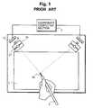
- FIG. 1illustrates an example of the conventional optical digitizers.
- a tunnel mirror 14is disposed in front of an image forming lens 9 for a linear image sensor 13 , and a pair of detecting units, wherein each of the units is arranged in such a manner that a light axis of an LED light source 31 coincides with a light axis of the linear image sensor 13 , are arranged in the peripheral area of a coordinate plane 1 .
- the tip of a pointing instrument 2such as a pen, is wrapped with a tape 22 composed of a retroreflective material.
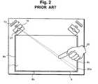
- FIG. 2Another example of a conventional optical digitizer is illustrated in FIG. 2 .
- the retroreflective materialis installed at the tip of the pen 2 , but in the conventional example illustrated in FIG. 2, the retroreflective material is installed on the frame of the coordinate plane 1 .
- the images in the retroreflective material 4 positioned at the two sides of the coordinate plane 1are taken by each of the right and left image sensors 13 .
- the right-side image sensortakes the images 4 a and 4 b of the retroreflective material
- the left-side image sensortakes the images 4 b and 4 c, respectively.
- the reflected light from the retroreflective material 4is intercepted by the pointing instrument 20 , and the shadow image 20 a is detected by the image sensor 13 , which makes it possible to detect the pointed coordinates of the pointing instrument 20 .
- a conventional optical digitizer as illustrated in FIG. 1allowed to input by a special pen only, which requires a pen even for making a simple input through a touch panel. Moreover, since it requires a specific pen, when it is loaded on a notebook-size personal computer, it is often inconvenient for a user.
- the conventional digitizer as illustrated in FIG. 2served the purpose as far as the inputting by a pen is concerned, but it did not solve the hand-touch problem.
- the present inventionaims to provide an optical digitizer, which has the function to recognize kinds of pointing instruments, and enables an input by both a finger and a pen. Moreover, the invention aims to provide an optical digitizer with a pointing instrument equipped with a plurality of functions by installing a supplemental information transmission means into the pointing instrument.
- the present inventionrelates to an optical digitizer which detects a position coordinate pointed by a pointing instrument on a coordinate plane, and has a function to recognize a first pointing instrument, which is not equipped with a retroreflective material, from a second pointing instrument, which is equipped with the retroreflective material at its tip, wherein the optical digitizer is comprised of a light source for emitting a light ray, an image taking means, which is placed in the periphery of the coordinate plane to take an image of the pointing instrument by using the light ray of the light source and convert the taken image into an electrical signal, a computing means for computing the position coordinates by processing the electrical signal converted by the image taking means, a light polarization means which is provided at the light source for polarizing the emitted light from the light source into a first polarized light or a second polarized light, a switching means with which irradiating light to the coordinate plane is switched to the first polarized light or the second polarized
- the light source meansis comprised of two sources, and the polarizing means is comprised of the first polarizing means, which allows the first polarized light to transmit, and the second polarizing means, which allows the second polarized light to transmit, both the polarizing means being installed at each light source, and the first polarized light and the second polarized light are alternately illuminated by irradiating the two light sources alternately through the switching means.
- the polarizing meanscomprises a first polarizing means, which allows the first polarized light to transmit, and a liquid crystal plate, so that the first polarized light and the second polarized light are illuminated by switching voltages applied to the liquid crystal plate by a switching means.
- the present inventionrelates to an optical digitizer which has a function to recognize kinds of a pointing instrument
- the optical digitizeris comprised of a light source to emit a light ray, an image taking means, installed in the peripheral area of the coordinate plane to take an image of the pointing instrument by using the light ray of the light source and to convert the taken image into an electrical signal, a calculation means to compute the pointed position coordinates by processing the converted electrical signal through the image taking means, a polarizing means which is installed in the image taking means to make the incident light as the first polarized light or the second polarized light, a dividing means to divide the incident light to the image taking means, a retroreflective material installed at the frame of aforementioned coordinate plane, which has retroreflective characteristics, a polarizing film which is installed in front of the retroreflective material, having a transmitting axis to cause the first polarized light ray to be transmitted, and a judgment means which judges the pointing instrument as a first pointing instrument if the image
- the present inventionfurther relates to an optical digitizer wherein the light source means is comprised of two light sources, further having a third polarizing means to cause the first polarized light to be transmitted, and a fourth polarized means to cause the second polarized light to be transmitted, both of them are installed at each of the two light sources, the optical digitizer further having a switching means to cause the two light sources alternately to be emitted, the second pointing instrument having a liquid crystal material at its tip, the optical digitizer further having a judging means to judge the state of the second pointing instrument in the case where the image of the pointing instrument is taken by the second polarized light, by the polarized light which comes into the image taking means in which the polarized light changes by the voltage applied to the liquid crystal material.
- the first polarized light raymay be a vertically polarized light ray
- the second polarized light raymay be a horizontally polarized light ray
- FIG. 1is a diagrammatic view of a conventional optical digitizer which uses a reflective type pen
- FIG. 2is a diagrammatic view of a conventional optical digitizer which enables an input by a finger
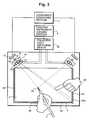
- FIG. 3is a plane view showing a first embodiment of the optical digitizer in accordance with the present invention.
- FIG. 4is a side view of the first embodiment of the optical digitizer shown in FIG. 3;
- FIG. 5is a flow chart to show the operation of the first embodiment shown in FIG. 3 in accordance with the present invention.
- FIG. 6is a plane view of a second embodiment of the optical digitizer in accordance with the present invention.
- FIG. 7is a side view of the second embodiment of the optical digitizer as shown in FIG. 4 in accordance with the present invention.
- FIG. 8is a plane view of a third embodiment of the optical digitizer in accordance with the present invention.
- FIG. 9is a plane view of a fourth embodiment of the optical digitizer in accordance with the present invention:
- FIG. 10is a plane view of a fifth embodiment of the optical digitizer in accordance with the present invention.
- FIG. 3is a diagrammatic plane view to show a first embodiment of the optical digitizer in accordance with the present invention
- FIG. 4is its schematic side view.
- Each detecting unit 3is comprised of a light source, a linear image sensor 13 , a lens 9 to form an image thereon, and a tunnel mirror 14 in which the light axis of the light source and the light axis of the linear image sensor are arranged to coincide.
- a retroreflective material 4 installed at the frame surrounding the coordinate plane 1is basically the same as the prior art shown in FIG.
- the characteristics of the present inventionare that two LEDs 31 and 32 are used as the light source, polarizing films 41 , 42 in which polarizing axes are orthogonal therebetween, are provided to the LEDs, and a polarizing film 40 is further installed in front of the retroreflective material 4 .
- the detecting units on the right and leftare identical in their configuration, so that only one is described and the explanation of the other is omitted.
- the vertically polarizing film 40which allows vertically polarized light rays to be transmitted
- the vertically polarizing film 41which allows vertically polarized light rays to be transmitted
- the horizontally polarizing film 42which allows horizontally polarized light rays to be transmitted
- the tunnel mirrorcan also employ a half mirror or a pin hole or the like, or it is permissible to arrange the light source and the image sensor at an extremely close distance, thus an appropriate modification can be made.
- the LED 31is equipped with the vertically polarizing film 41
- the LED 32is equipped with the horizontally polarizing film 42 respectively, and the light emissions of the LEDs 31 and 32 are switched by a polarized light switching device 35 in order to alternately illuminate the vertically polarized light and the horizontally polarized light on the coordinate plane 1 .
- the light ray emitted from the light sourceenters into the coordinate plane 1 by the tunnel mirror 14 .
- the LED 31is illuminated to cause the vertically polarized light to enter into the frame of the coordinate plane 1 , the light transmits through the vertically polarizing film 41 and enters into the retroreflective material 4 , and returns in the same direction as the direction in which the light came from, so that at each of the image sensors 13 at the right and the left, the image of the retroreflective material positioned at two sides of the coordinate plane 1 is reflected.
- the right image sensorthe images of the retroreflective materials 4 a and 4 b are taken
- the left image sensorthe images of the retroreflective materials 4 b and 4 c are taken, respectively.
- the microprocessor in a coordinate computing section 7will determine the two dimensional coordinates (X, Y) by using the triangulation principle.
- the pointing instrument judging section 8judges whether the pointing instrument is a finger or a pen from the state of the polarization switching device 35 and the taken image signals. In other words, in the case where the image of the pointing instrument is taken by the sensor 13 when the vertically polarized light ray is illuminated, the finger 20 , and in the case where the image of the pointing instrument is taken by the image sensor 13 when the horizontally polarized light ray is illuminated, then it is judged as the pen 2 .
- FIG. 5shows a flow chart to explain the operation of the first embodiment of the optical digitizer in accordance with the present invention as illustrated in FIG. 3 .
- the polarized light switching device 35is switched to cause the LED 32 to emit light that illuminates the horizontally polarized light rays (Step S 1 ).
- the checkingis made whether the reflected light from the retroreflective material 22 installed at the tip of the pen 2 is detected or not (Step S 2 ).
- the pen coordinate computing processis conducted (Step S 5 ), the pointed position coordinates of the pen are detected, and the same procedure is repeated by returning to Step S 2 .
- Step S 3the polarized light switching device 35 is switched and the LED 31 is made to emit the light, and the vertically polarized light rays are illuminated.
- Step S 4the checking is made whether the reflected light from the retroreflective material 4 installed at the frame of the coordinates plane 1 is blocked by the finger 20 , and the image of its shadow 20 a is detected or not.
- the finger coordinates computing processis conducted (Step S 6 ), and after detecting the pointed position coordinates of the finger, the step returns to Step S 1 .
- Step S 1the step returns to Step S 1 , and the existence or non-existence of the reflected light from the retroreflective material of the pen is detected. Subsequently, this procedure is repeated at a high speed.
- the optical digitizer in accordance with the present inventionfirst detects the existence or non-existence of the pen which has the retroreflective material. If the pen is detected, then the coordinate computing process is conducted. If the pen is not detected, then, the existence or non-existence of the finger is detected. In this way, what pointing instrument is used can be recognized, and then the input with either a finger or a pen is available. Moreover, if the existence of a pen is detected, even if both a pen and a finger are detected, the kinds of the pointing instrument is recognized as the pen, so that there is no problem of the hand-touch problem during the pen-input.
- 1 ⁇ 4 wavelength phase contrast filmin lieu of the vertically polarizing film 40 shown in FIG. 3, and install a vertically polarizing film in front of the image sensor 13 .
- the 1 ⁇ 4 wavelength phase contrast filmis one in which, when a light goes back and forth therethrough, the polarized light is rotated at 90 degrees. Therefore, in this case, when the horizontally polarized light ray is illuminated, the reflected light from the retroreflective material 4 becomes a vertically polarized light ray, so that the image of the finger 20 as a shadow is taken by the sensor 13 .
- the reflected light from the retroreflective material 4becomes a horizontally polarized light ray, so that the reflected light from the retroreflective material 4 is not detected by the image sensor 13 .
- the pen 2 which has the retroreflective material 22is on the coordinate plane 1 , then, because the reflected light from the retroreflective material 22 is the vertically polarized light ray, its image is taken by the image sensor 13 via the vertically polarizing film installed in front of the image sensor 13 .
- the configuration in this manneris also capable of performing the same operation as the aforementioned embodiment.
- FIG. 6is a diagrammatic plane view of the second embodiment of the optical digitizer in accordance with the present invention
- FIG. 7is its schematic side view.
- each detecting unitis configured to have a light source and two polarizing films installed in it, but in this embodiment, a liquid crystal plate 50 is installed on top of the horizontally polarizing film 42 installed at the LED 32 , thereby using one light source and one polarizing film in each detecting unit.
- the vertically polarized light ray and the horizontally polarized light rayare illuminated alternately, but in this embodiment, by turning on/off the voltage applied to the liquid crystal plate 50 , the vertically polarized light ray and horizontally polarized light ray are illuminated alternately.
- the liquid crystal plate 50 used in this embodimentis comprised of a TN (Twisted Nematic) type liquid crystal.
- the TN-type liquid crystaluses the optical rotation (twist) of the light.
- the one with the applied voltage being OFF, and the orientation of the liquid crystal molecules being 90 degrees twisted between the plates (top/bottom)may be used in this embodiment. In this manner, the light entered into the liquid crystal is rotated 90 degrees and passed.
- the voltageis applied, then the liquid crystal molecules change to the same direction (direction between the plates), and the entered light passes through without being twisted.
- the light ray from the LED 32becomes the horizontally polarized light ray because of the horizontally polarizing film 42 , and when the voltage is applied to the liquid crystal plate 50 , the light ray is not rotated and passes through the liquid crystal plate 50 , and the horizontally polarized light ray enters on the coordinate plane 1 .
- the polarizing axisis rotated at 90 degrees by the liquid crystal plate 50 , and the vertically polarized light ray enters on the coordinate plane 1 .
- the pen 2is detected by the horizontally polarized light ray
- the finger 20is detected by the vertically polarized light ray
- the kinds of the pointing instrumentcan be recognized.
- the present embodimentuses only one LED, which has the advantage of making the light source small. Moreover, the light axis of the light source does not change, so that the position alignment is simple, and the computing of the pointed position coordinates does not become complicated, and the margin of error becomes small.
- FIG. 8is a diagrammatic plane view of a third embodiment of the optical digitizer in accordance with the present invention.
- a polarizing filmis installed at the light source, but in this embodiment, each detecting unit is equipped with two image sensors, and the polarizing film is installed at the image sensor side.
- a half mirror 45is arranged in such a way for the light ray from the coordinate plane 1 to enter into each image forming surface of the two image sensors 13 a and 13 b, and the vertically polarizing film 41 and horizontally polarizing film 42 are installed to these image sensors 13 a and 13 b, respectively.
- the reflective light of the illuminated light on the coordinate plane 1becomes the vertically polarized light ray by the vertically polarizing film 40 , which is installed at the retroreflective material 4 at the frame of the coordinate plane 1 . Consequently, only the image sensor 13 a equipped with the vertically polarizing film 41 which causes only the vertically polarized light ray to be transmitted, takes the image of the reflective light of the retroreflective material 4 at the frame of the coordinate plane 1 . In the case where the finger 20 is placed on the coordinate plane 1 as the pointing instrument, the image of its shadow can be taken by the image sensor 13 a, and the position pointing coordinates of the finger 20 can be detected.
- the pointing instrumentis a pen which has a retroreflective material, or a finger.
- FIG. 9is a diagrammatic plane view of a fourth embodiment of the optical digitizer in accordance with the present invention.
- the third embodimenttwo image sensors are used, but in this embodiment, one image sensor is used, and a liquid crystal plate is installed in front of the polarizing film.
- the horizontally polarizing film 42is installed in front of the image sensor 13
- the liquid crystal plate 50is installed in front of the film.
- the image of the position pointing coordinates of the pencan be taken by the image sensor. If there is no image to be taken by the image sensor 13 , then the voltage is not applied to the liquid crystal plate 50 , and the digitizer is set for the state to be able to take the image of only the vertically polarizing light ray by the image sensor 13 . At this time, if the finger 20 is on the coordinate plane 1 , then the image of the shadow of the finger 20 is taken by the image sensor 13 .
- These operationsare the same as those shown in the flow chart in FIG. 5, which is used to illustrate the operations for the first embodiment.
- FIG. 10is a diagrammatic plane view of a fifth embodiment of the optical digitizer in accordance with the present invention.
- FIG. 11is a detailed drawing of the pointing instrument to be used in this embodiment.
- the configuration of this embodimentis like a combination of the first and second embodiments.
- each detecting unituses LEDs 31 and 32 as the light sources, and the vertically polarizing film 41 a and the horizontally polarizing film 42 a are installed to each light source, respectively.
- two image sensors 13 a and 13 bare used as an image taking means
- a half mirror 45is arranged in such a manner that the light rays from the coordinate plane 1 enter into the respective image forming surface
- the vertically polarizing film 41 b and horizontally polarizing film 42 bare installed at each of the image sensors 13 a and 13 b.
- the pen 48which is the pointing instrument used in this embodiment, is equipped with the retroreflective material 22 at its tip, and furthermore, as shown in FIG. 11, is surrounded by the liquid crystal material 55 .
- This liquid crystal material 55is to rotate the polarizing direction by 45 degrees depending on the existence or non-existence of the applied voltage on it.
- the liquid crystal material 55is comprised of the TN-type liquid crystal, and the orientation of orientational membranes is differentiated by 45 degrees. Consequently, the incident light entered into the liquid crystal 55 passes therethrough with a 45 degree rotation depending on the existence or the non-existence of the applied voltage.
- the LEDs 31 and 32are connected to the polarizing light switching device 35 , and the two LEDs are caused to be emitted alternately, and thus the vertically polarizing light ray and the horizontally polarized light ray are alternately illuminated.
- the LED 31When the LED 31 emits the light and only the vertically polarizing light ray is illuminated, there is reflective light from the retroreflective material 4 installed at the frame of the coordinate plane 1 via the vertically polarizing film 40 , so that the image of the reflected light is taken by the image sensor 13 a via the vertically polarizing film 41 b.
- the finger 20is placed on the coordinate plane 1 , the image of its shadow is taken by the image sensor 13 a, the result is converted into the electrical signal, and the pointing position coordinates can be detected.
- the LEDis switched by the polarizing light switching device 35 and the LED 32 emits the light, the horizontally polarizing light is illuminated.
- the polarizing axis of the horizontally polarized incident light rayrotates 45 degrees by the liquid crystal material 55 .
- the light ray reflected from the retroreflective material 22rotates 45 degrees again by the liquid crystal material 55 , so after all it rotates 90 degrees and becomes the vertically polarizing light ray, and returns from the pen 48 .
- the position pointing coordinates of the pencan be detected by the image sensor 13 a via the vertically polarizing film 41 b.
- the voltageis applied to the liquid crystal material 55 , then the light passes straight through the liquid crystal material 55 , and the reflected light from the retroreflective material 22 enters into the image sensor 13 b via the horizontally polarizing film 42 b. In this case, the position pointing coordinates of the pen can be detected by the image sensor 13 b.
- the differences in the finger 20 , the pen 48 without being applied voltage, and the pen 48 with being applied voltagecan be recognized, so that the supplemental information on the pointing instrument, for example, may be transmitted. Therefore, if this embodiment is applied to an electronic whiteboard, the normal input by pen 48 is to be black color input, the input is turned into the red input by pressing the switch 25 , and further a finger input is as a function of an eraser, so that an excellent whiteboard with good input efficiency can be obtained.
- the detecting unit section in this embodimentcan be configured as the fourth embodiment shown in FIG. 9 .
- the number of the image sensors to be usedmay be reduced.
- the present inventionis not limited to the above illustrated representations, and may be embodied in several forms without departing from the spirit of the essential characteristics thereof.
- the vertically polarizing film 40as shown in FIG. 3, it is possible to configure the device by using the retroreflective material 4 installed at the frame of the coordinate plane 1 in which the reflective efficiency rate is inferior to the reflective efficiency rate of the retroreflective material installed at the tip of the pen 2 .
- the kinds of the pointing instrumentscan be recognized by the strength of the light ray of the image taken by the image sensor 13 .
- the optical digitizer in accordance with the present inventionhas the recognizing function of the kinds of the pointing instruments, to enable the input either by a pen or by a finger.
- this inventionis free from the hand-touch problem.
- the present inventionallows for the transmittance of supplemental information, it is possible to cause a pen to have a plurality of functions.
Landscapes
- Engineering & Computer Science (AREA)
- General Engineering & Computer Science (AREA)
- Theoretical Computer Science (AREA)
- Human Computer Interaction (AREA)
- Physics & Mathematics (AREA)
- General Physics & Mathematics (AREA)
- Position Input By Displaying (AREA)
Abstract
Description
Claims (15)
Applications Claiming Priority (2)
| Application Number | Priority Date | Filing Date | Title |
|---|---|---|---|
| JP11/320483 | 1999-11-11 | ||
| JP32048399AJP3819654B2 (en) | 1999-11-11 | 1999-11-11 | Optical digitizer with indicator identification function |
Publications (1)
| Publication Number | Publication Date |
|---|---|
| US6498602B1true US6498602B1 (en) | 2002-12-24 |
Family
ID=18121959
Family Applications (1)
| Application Number | Title | Priority Date | Filing Date |
|---|---|---|---|
| US09/708,767Expired - LifetimeUS6498602B1 (en) | 1999-11-11 | 2000-11-07 | Optical digitizer with function to recognize kinds of pointing instruments |
Country Status (5)
| Country | Link |
|---|---|
| US (1) | US6498602B1 (en) |
| EP (1) | EP1100041A2 (en) |
| JP (1) | JP3819654B2 (en) |
| KR (1) | KR20010051589A (en) |
| CN (1) | CN1296239A (en) |
Cited By (80)
| Publication number | Priority date | Publication date | Assignee | Title |
|---|---|---|---|---|
| US20030160155A1 (en)* | 2001-10-09 | 2003-08-28 | Liess Martin Dieter | Device having touch sensitivity functionality |
| US6654008B2 (en)* | 2000-11-27 | 2003-11-25 | Matsushita Electric Industrial Co., Ltd. | Electronic whiteboard and penholder used for the same |
| US20040207858A1 (en)* | 2000-04-14 | 2004-10-21 | Fujitsu Limited | Optical position detecting device and recording medium |
| US20050178953A1 (en)* | 2004-02-17 | 2005-08-18 | Stephen Worthington | Apparatus for detecting a pointer within a region of interest |
| US20060001653A1 (en)* | 2004-06-30 | 2006-01-05 | National Semiconductor Corporation | Apparatus and method for a folded optical element waveguide for use with light based touch screens |
| US20060028457A1 (en)* | 2004-08-08 | 2006-02-09 | Burns David W | Stylus-Based Computer Input System |
| US20070152986A1 (en)* | 2001-10-09 | 2007-07-05 | Eit Co., Ltd. | Coordinate input device working with at least display screen and desk-top surface as the pointing areas thereof |
| US20070285404A1 (en)* | 2006-06-13 | 2007-12-13 | N-Trig Ltd. | Fingertip touch recognition for a digitizer |
| US20080012835A1 (en)* | 2006-07-12 | 2008-01-17 | N-Trig Ltd. | Hover and touch detection for digitizer |
| US20080012838A1 (en)* | 2006-07-13 | 2008-01-17 | N-Trig Ltd. | User specific recognition of intended user interaction with a digitizer |
| US20080100593A1 (en)* | 2006-10-31 | 2008-05-01 | Peter Skillman | Light sensitive display interface for computing devices |
| US20080291164A1 (en)* | 2006-08-22 | 2008-11-27 | Canon Kabushiki Kaisha | Coordinate input apparatus, control method thereof, and program |
| US20090122008A1 (en)* | 2007-11-14 | 2009-05-14 | Boulder Innovation Group, Inc. | Probe With A Virtual Marker |
| US20090309841A1 (en)* | 2008-06-13 | 2009-12-17 | Polyvision Corporation | Eraser for use with optical interactive surface |
| US20100066016A1 (en)* | 2006-09-13 | 2010-03-18 | Koninklijke Philips Electronics N.V. | Determining the orientation of an object |
| US20100090950A1 (en)* | 2008-10-10 | 2010-04-15 | Hsin-Chia Chen | Sensing System and Method for Obtaining Position of Pointer thereof |
| US20100141963A1 (en)* | 2008-10-10 | 2010-06-10 | Pixart Imaging Inc. | Sensing System and Locating Method thereof |
| CN101770317A (en)* | 2010-03-16 | 2010-07-07 | 南京方瑞科技有限公司 | Touch electronic whiteboard |
| US20100321309A1 (en)* | 2009-06-22 | 2010-12-23 | Sonix Technology Co., Ltd. | Touch screen and touch module |
| US20110080371A1 (en)* | 2009-10-06 | 2011-04-07 | Pixart Imaging Inc. | Resistive touch controlling system and sensing method |
| US20110080363A1 (en)* | 2009-10-06 | 2011-04-07 | Pixart Imaging Inc. | Touch-control system and touch-sensing method thereof |
| WO2011047459A1 (en)* | 2009-10-23 | 2011-04-28 | Smart Technologies Ulc | Touch-input system with selectively reflective bezel |
| US20110128219A1 (en)* | 2009-12-01 | 2011-06-02 | Smart Technologies, Inc. | Interactive input system and bezel therefor |
| US20110175849A1 (en)* | 2010-01-18 | 2011-07-21 | Acer Incorporated | Optical touch display device and method |
| US20110205244A1 (en)* | 2010-02-25 | 2011-08-25 | Bob Myers | Stylus input system |
| US20110234542A1 (en)* | 2010-03-26 | 2011-09-29 | Paul Marson | Methods and Systems Utilizing Multiple Wavelengths for Position Detection |
| USRE42794E1 (en) | 1999-12-27 | 2011-10-04 | Smart Technologies Ulc | Information-inputting device inputting contact point of object on recording surfaces as information |
| WO2011120144A1 (en) | 2010-04-01 | 2011-10-06 | Smart Technologies Ulc | Interactive input system and pen tool therefor |
| US8055022B2 (en) | 2000-07-05 | 2011-11-08 | Smart Technologies Ulc | Passive touch system and method of detecting user input |
| US20110298708A1 (en)* | 2010-06-07 | 2011-12-08 | Microsoft Corporation | Virtual Touch Interface |
| US20110298756A1 (en)* | 2010-06-03 | 2011-12-08 | Lg Display Co., Ltd. | Touch panel integrated display device |
| US20110304859A1 (en)* | 2010-06-11 | 2011-12-15 | Seiko Epson Corporation | Processing device, optical detection device, and display device |
| US20110304592A1 (en)* | 2001-12-31 | 2011-12-15 | Booth Jr Lawrence A | Energy sensing light emitting diode display |
| US8089462B2 (en) | 2004-01-02 | 2012-01-03 | Smart Technologies Ulc | Pointer tracking across multiple overlapping coordinate input sub-regions defining a generally contiguous input region |
| USRE43084E1 (en) | 1999-10-29 | 2012-01-10 | Smart Technologies Ulc | Method and apparatus for inputting information including coordinate data |
| US8094137B2 (en) | 2007-07-23 | 2012-01-10 | Smart Technologies Ulc | System and method of detecting contact on a display |
| US8115753B2 (en) | 2007-04-11 | 2012-02-14 | Next Holdings Limited | Touch screen system with hover and click input methods |
| US8120596B2 (en) | 2004-05-21 | 2012-02-21 | Smart Technologies Ulc | Tiled touch system |
| US20120075206A1 (en)* | 2010-09-24 | 2012-03-29 | Fuji Xerox Co., Ltd. | Motion detecting device, recording system, computer readable medium, and motion detecting method |
| US8149221B2 (en) | 2004-05-07 | 2012-04-03 | Next Holdings Limited | Touch panel display system with illumination and detection provided from a single edge |
| US20120098795A1 (en)* | 2010-10-20 | 2012-04-26 | Pixart Imaging Inc. | Optical touch screen system and sensing method for the same |
| US20120176340A1 (en)* | 2011-01-10 | 2012-07-12 | Young Lighting Technology Corporation | Touch module and touch detecting method |
| US20120179977A1 (en)* | 2011-01-12 | 2012-07-12 | Smart Technologies Ulc | Method of supporting multiple selections and interactive input system employing same |
| US8228304B2 (en) | 2002-11-15 | 2012-07-24 | Smart Technologies Ulc | Size/scale orientation determination of a pointer in a camera-based touch system |
| US8274496B2 (en) | 2004-04-29 | 2012-09-25 | Smart Technologies Ulc | Dual mode touch systems |
| US20120242622A1 (en)* | 2011-03-21 | 2012-09-27 | Yu Tseng | Touch module |
| US8289299B2 (en) | 2003-02-14 | 2012-10-16 | Next Holdings Limited | Touch screen signal processing |
| US8339378B2 (en) | 2008-11-05 | 2012-12-25 | Smart Technologies Ulc | Interactive input system with multi-angle reflector |
| US20130016071A1 (en)* | 2011-07-14 | 2013-01-17 | 3M Innovative Properties Company | Digitizer using position-unique optical signals |
| US20130016527A1 (en)* | 2011-07-14 | 2013-01-17 | 3M Innovative Properties Company | Light guide for backlight |
| US20130016072A1 (en)* | 2011-07-14 | 2013-01-17 | 3M Innovative Properties Company | Digitizer for multi-display system |
| US8384693B2 (en) | 2007-08-30 | 2013-02-26 | Next Holdings Limited | Low profile touch panel systems |
| US8405637B2 (en) | 2008-01-07 | 2013-03-26 | Next Holdings Limited | Optical position sensing system and optical position sensor assembly with convex imaging window |
| US20130088462A1 (en)* | 2010-07-27 | 2013-04-11 | Chi W. So | System and method for remote touch detection |
| US20130100084A1 (en)* | 2010-08-02 | 2013-04-25 | Lg Innotek Co., Ltd. | Optical touch screen and method for assembling the same |
| US8432377B2 (en) | 2007-08-30 | 2013-04-30 | Next Holdings Limited | Optical touchscreen with improved illumination |
| US8456451B2 (en)* | 2003-03-11 | 2013-06-04 | Smart Technologies Ulc | System and method for differentiating between pointers used to contact touch surface |
| US8456447B2 (en) | 2003-02-14 | 2013-06-04 | Next Holdings Limited | Touch screen signal processing |
| US8456418B2 (en) | 2003-10-09 | 2013-06-04 | Smart Technologies Ulc | Apparatus for determining the location of a pointer within a region of interest |
| US20130154985A1 (en)* | 2010-08-25 | 2013-06-20 | Hitachi Solutions, Ltd. | Interactive whiteboards and programs |
| US8508508B2 (en) | 2003-02-14 | 2013-08-13 | Next Holdings Limited | Touch screen signal processing with single-point calibration |
| US20130241820A1 (en)* | 2012-03-13 | 2013-09-19 | Samsung Electronics Co., Ltd. | Portable projector and image projecting method thereof |
| TWI410842B (en)* | 2009-12-31 | 2013-10-01 | Acer Inc | Touch display system |
| US8687172B2 (en) | 2011-04-13 | 2014-04-01 | Ivan Faul | Optical digitizer with improved distance measurement capability |
| US8692768B2 (en) | 2009-07-10 | 2014-04-08 | Smart Technologies Ulc | Interactive input system |
| US8902193B2 (en) | 2008-05-09 | 2014-12-02 | Smart Technologies Ulc | Interactive input system and bezel therefor |
| US9075479B2 (en) | 2010-07-13 | 2015-07-07 | Shoei Co., Ltd. | Input device and method using an optical touch panel and a contact touch panel |
| US20160018947A1 (en)* | 2014-07-15 | 2016-01-21 | Quanta Computer Inc. | Optical touch-control system |
| US20160077669A1 (en)* | 2011-09-16 | 2016-03-17 | Hewlett-Packard Development Company, L.P. | Positional input systems and methods |
| US9442607B2 (en)* | 2006-12-04 | 2016-09-13 | Smart Technologies Inc. | Interactive input system and method |
| US20160328088A1 (en)* | 2009-05-18 | 2016-11-10 | Pixart Imaging Inc. | Controlling method for a sensing system |
| US9557837B2 (en) | 2010-06-15 | 2017-01-31 | Pixart Imaging Inc. | Touch input apparatus and operation method thereof |
| US10025492B2 (en)* | 2016-02-08 | 2018-07-17 | Microsoft Technology Licensing, Llc | Pointing detection |
| US20190227670A1 (en)* | 2018-01-23 | 2019-07-25 | Rapt Ip Limited | Compliant Stylus Interaction |
| US20190377431A1 (en)* | 2018-06-06 | 2019-12-12 | Rapt Ip Limited | Stylus with a control |
| US10627960B2 (en) | 2014-09-02 | 2020-04-21 | Rapt Ip Limited | Instrument detection with an optical touch sensitive device, with associating contacts with active instruments |
| CN112703538A (en)* | 2018-12-12 | 2021-04-23 | 株式会社东芝 | Reading support system, mobile object, reading support method, program, and storage medium |
| US11003284B2 (en) | 2018-06-12 | 2021-05-11 | Beechrock Limited | Touch sensitive device with a camera |
| US11036338B2 (en) | 2018-04-20 | 2021-06-15 | Beechrock Limited | Touch object discrimination by characterizing and classifying touch events |
| US12353664B1 (en)* | 2022-09-28 | 2025-07-08 | Amazon Technologies, Inc. | Registering selections of graphical elements on electronic displays using time-of-flight sensors |
Families Citing this family (15)
| Publication number | Priority date | Publication date | Assignee | Title |
|---|---|---|---|---|
| JP4828746B2 (en)* | 2001-09-20 | 2011-11-30 | 株式会社リコー | Coordinate input device |
| JP2003093741A (en)* | 2001-09-26 | 2003-04-02 | Namco Ltd | Game device |
| US7633633B2 (en)* | 2003-08-29 | 2009-12-15 | Avago Technologies Ecbu Ip (Singapore) Pte. Ltd. | Position determination that is responsive to a retro-reflective object |
| JP4072732B2 (en)* | 2004-10-29 | 2008-04-09 | ソニー株式会社 | INPUT / OUTPUT DEVICE AND METHOD, RECORDING MEDIUM, AND PROGRAM |
| WO2008007276A2 (en)* | 2006-06-28 | 2008-01-17 | Koninklijke Philips Electronics, N.V. | Method and apparatus for object learning and recognition based on optical parameters |
| KR100849322B1 (en) | 2006-11-20 | 2008-07-29 | 삼성전자주식회사 | Touch screen using image sensor |
| CN101833400B (en)* | 2009-03-10 | 2012-06-13 | 广达电脑股份有限公司 | Optical sensing screen and panel sensing method |
| KR101715851B1 (en)* | 2009-12-15 | 2017-03-15 | 엘지디스플레이 주식회사 | Optical Sensing Unit, Display Module and Display Device Using the Same |
| WO2011086600A1 (en)* | 2010-01-15 | 2011-07-21 | パイオニア株式会社 | Information-processing device and method thereof |
| JP2011192314A (en)* | 2011-07-05 | 2011-09-29 | Ricoh Co Ltd | Coordinate input device |
| TWI464649B (en)* | 2012-03-22 | 2014-12-11 | Quanta Comp Inc | Optical touch system |
| JP6201519B2 (en)* | 2013-08-21 | 2017-09-27 | 株式会社リコー | Coordinate detection apparatus, coordinate detection method, and electronic information board system |
| US10402017B2 (en)* | 2014-09-02 | 2019-09-03 | Rapt Ip Limited | Instrument detection with an optical touch sensitive device |
| JP6683173B2 (en)* | 2017-05-15 | 2020-04-15 | フジテック株式会社 | Elevator equipment |
| CN107942529B (en)* | 2017-12-21 | 2024-05-21 | 北京镭宝光电技术有限公司 | Pulse width switching coaxial co-polarized laser and coaxial co-polarized laser output method |
Citations (8)
| Publication number | Priority date | Publication date | Assignee | Title |
|---|---|---|---|---|
| US3613066A (en)* | 1968-10-22 | 1971-10-12 | Cii | Computer input equipment |
| US4811004A (en)* | 1987-05-11 | 1989-03-07 | Dale Electronics, Inc. | Touch panel system and method for using same |
| US5248856A (en)* | 1992-10-07 | 1993-09-28 | Microfield Graphics, Inc. | Code-based, electromagnetic-field-responsive graphic data-acquisition system |
| US5484966A (en)* | 1993-12-07 | 1996-01-16 | At&T Corp. | Sensing stylus position using single 1-D image sensor |
| US5525764A (en)* | 1994-06-09 | 1996-06-11 | Junkins; John L. | Laser scanning graphic input system |
| US5889879A (en)* | 1995-05-11 | 1999-03-30 | Tsai; Yeong-Shyeong | Object recognizer |
| JPH11110116A (en)* | 1997-08-07 | 1999-04-23 | Fujitsu Ltd | Optical position detector |
| US6100538A (en)* | 1997-06-13 | 2000-08-08 | Kabushikikaisha Wacom | Optical digitizer and display means for providing display of indicated position |
- 1999
- 1999-11-11JPJP32048399Apatent/JP3819654B2/ennot_activeExpired - Fee Related
- 2000
- 2000-11-06EPEP00309832Apatent/EP1100041A2/ennot_activeWithdrawn
- 2000-11-07USUS09/708,767patent/US6498602B1/ennot_activeExpired - Lifetime
- 2000-11-10KRKR1020000066657Apatent/KR20010051589A/ennot_activeWithdrawn
- 2000-11-13CNCN00133910Apatent/CN1296239A/enactivePending
Patent Citations (8)
| Publication number | Priority date | Publication date | Assignee | Title |
|---|---|---|---|---|
| US3613066A (en)* | 1968-10-22 | 1971-10-12 | Cii | Computer input equipment |
| US4811004A (en)* | 1987-05-11 | 1989-03-07 | Dale Electronics, Inc. | Touch panel system and method for using same |
| US5248856A (en)* | 1992-10-07 | 1993-09-28 | Microfield Graphics, Inc. | Code-based, electromagnetic-field-responsive graphic data-acquisition system |
| US5484966A (en)* | 1993-12-07 | 1996-01-16 | At&T Corp. | Sensing stylus position using single 1-D image sensor |
| US5525764A (en)* | 1994-06-09 | 1996-06-11 | Junkins; John L. | Laser scanning graphic input system |
| US5889879A (en)* | 1995-05-11 | 1999-03-30 | Tsai; Yeong-Shyeong | Object recognizer |
| US6100538A (en)* | 1997-06-13 | 2000-08-08 | Kabushikikaisha Wacom | Optical digitizer and display means for providing display of indicated position |
| JPH11110116A (en)* | 1997-08-07 | 1999-04-23 | Fujitsu Ltd | Optical position detector |
Cited By (137)
| Publication number | Priority date | Publication date | Assignee | Title |
|---|---|---|---|---|
| USRE43084E1 (en) | 1999-10-29 | 2012-01-10 | Smart Technologies Ulc | Method and apparatus for inputting information including coordinate data |
| USRE42794E1 (en) | 1999-12-27 | 2011-10-04 | Smart Technologies Ulc | Information-inputting device inputting contact point of object on recording surfaces as information |
| US6927386B2 (en) | 2000-04-14 | 2005-08-09 | Fujitsu Limited | Optical position detecting device and recording medium including an operational defect judgment |
| US7075054B2 (en) | 2000-04-14 | 2006-07-11 | Fujitsu Limited | Optical position detecting device and recording medium including a detection of dust on a light retro-reflector |
| US20040218479A1 (en)* | 2000-04-14 | 2004-11-04 | Fujitsu Limited | Optical position detecting device and recording medium |
| US20040206889A1 (en)* | 2000-04-14 | 2004-10-21 | Fujitsu Limited | Optical position detecting device and recording medium |
| US6838657B2 (en) | 2000-04-14 | 2005-01-04 | Fujitsu Limited | Optical position detecting device and recording medium |
| US6844539B2 (en)* | 2000-04-14 | 2005-01-18 | Fujitsu Limited | Touch location by retroflected scanned optical beams |
| US20040207858A1 (en)* | 2000-04-14 | 2004-10-21 | Fujitsu Limited | Optical position detecting device and recording medium |
| US8055022B2 (en) | 2000-07-05 | 2011-11-08 | Smart Technologies Ulc | Passive touch system and method of detecting user input |
| US8378986B2 (en) | 2000-07-05 | 2013-02-19 | Smart Technologies Ulc | Passive touch system and method of detecting user input |
| US8203535B2 (en) | 2000-07-05 | 2012-06-19 | Smart Technologies Ulc | Passive touch system and method of detecting user input |
| US6654008B2 (en)* | 2000-11-27 | 2003-11-25 | Matsushita Electric Industrial Co., Ltd. | Electronic whiteboard and penholder used for the same |
| US6816537B2 (en)* | 2001-10-09 | 2004-11-09 | Koninklijke Philips Electronics N.V. | Device having touch sensitivity functionality |
| US20030160155A1 (en)* | 2001-10-09 | 2003-08-28 | Liess Martin Dieter | Device having touch sensitivity functionality |
| US20070152986A1 (en)* | 2001-10-09 | 2007-07-05 | Eit Co., Ltd. | Coordinate input device working with at least display screen and desk-top surface as the pointing areas thereof |
| US7414617B2 (en)* | 2001-10-09 | 2008-08-19 | Eit Co., Ltd. | Coordinate input device working with at least display screen and desk-top surface as the pointing areas thereof |
| US9665211B2 (en)* | 2001-12-31 | 2017-05-30 | Intel Corporation | Energy sensing light emitting diode display |
| US10241624B2 (en)* | 2001-12-31 | 2019-03-26 | Intel Corporation | Energy sensing light emitting diode display |
| US20110304592A1 (en)* | 2001-12-31 | 2011-12-15 | Booth Jr Lawrence A | Energy sensing light emitting diode display |
| US8963817B2 (en)* | 2001-12-31 | 2015-02-24 | Intel Corporation | Energy sensing light emitting diode display |
| US8228304B2 (en) | 2002-11-15 | 2012-07-24 | Smart Technologies Ulc | Size/scale orientation determination of a pointer in a camera-based touch system |
| US8456447B2 (en) | 2003-02-14 | 2013-06-04 | Next Holdings Limited | Touch screen signal processing |
| US8508508B2 (en) | 2003-02-14 | 2013-08-13 | Next Holdings Limited | Touch screen signal processing with single-point calibration |
| US8289299B2 (en) | 2003-02-14 | 2012-10-16 | Next Holdings Limited | Touch screen signal processing |
| US8466885B2 (en) | 2003-02-14 | 2013-06-18 | Next Holdings Limited | Touch screen signal processing |
| US8456451B2 (en)* | 2003-03-11 | 2013-06-04 | Smart Technologies Ulc | System and method for differentiating between pointers used to contact touch surface |
| US8456418B2 (en) | 2003-10-09 | 2013-06-04 | Smart Technologies Ulc | Apparatus for determining the location of a pointer within a region of interest |
| US8089462B2 (en) | 2004-01-02 | 2012-01-03 | Smart Technologies Ulc | Pointer tracking across multiple overlapping coordinate input sub-regions defining a generally contiguous input region |
| US20050178953A1 (en)* | 2004-02-17 | 2005-08-18 | Stephen Worthington | Apparatus for detecting a pointer within a region of interest |
| US7232986B2 (en)* | 2004-02-17 | 2007-06-19 | Smart Technologies Inc. | Apparatus for detecting a pointer within a region of interest |
| US8274496B2 (en) | 2004-04-29 | 2012-09-25 | Smart Technologies Ulc | Dual mode touch systems |
| US8149221B2 (en) | 2004-05-07 | 2012-04-03 | Next Holdings Limited | Touch panel display system with illumination and detection provided from a single edge |
| US8120596B2 (en) | 2004-05-21 | 2012-02-21 | Smart Technologies Ulc | Tiled touch system |
| US20060001653A1 (en)* | 2004-06-30 | 2006-01-05 | National Semiconductor Corporation | Apparatus and method for a folded optical element waveguide for use with light based touch screens |
| US8184108B2 (en)* | 2004-06-30 | 2012-05-22 | Poa Sana Liquidating Trust | Apparatus and method for a folded optical element waveguide for use with light based touch screens |
| US20060028457A1 (en)* | 2004-08-08 | 2006-02-09 | Burns David W | Stylus-Based Computer Input System |
| US20070285404A1 (en)* | 2006-06-13 | 2007-12-13 | N-Trig Ltd. | Fingertip touch recognition for a digitizer |
| US8059102B2 (en)* | 2006-06-13 | 2011-11-15 | N-Trig Ltd. | Fingertip touch recognition for a digitizer |
| US9535598B2 (en) | 2006-07-12 | 2017-01-03 | Microsoft Technology Licensing, Llc | Hover and touch detection for a digitizer |
| US20080012835A1 (en)* | 2006-07-12 | 2008-01-17 | N-Trig Ltd. | Hover and touch detection for digitizer |
| US9069417B2 (en) | 2006-07-12 | 2015-06-30 | N-Trig Ltd. | Hover and touch detection for digitizer |
| US10031621B2 (en) | 2006-07-12 | 2018-07-24 | Microsoft Technology Licensing, Llc | Hover and touch detection for a digitizer |
| US20080012838A1 (en)* | 2006-07-13 | 2008-01-17 | N-Trig Ltd. | User specific recognition of intended user interaction with a digitizer |
| US8686964B2 (en) | 2006-07-13 | 2014-04-01 | N-Trig Ltd. | User specific recognition of intended user interaction with a digitizer |
| US8780083B2 (en)* | 2006-08-22 | 2014-07-15 | Canon Kabushiki Kaisha | Coordinate input apparatus, control method thereof, and program |
| US20080291164A1 (en)* | 2006-08-22 | 2008-11-27 | Canon Kabushiki Kaisha | Coordinate input apparatus, control method thereof, and program |
| US8167698B2 (en)* | 2006-09-13 | 2012-05-01 | Koninklijke Philips Electronics N.V. | Determining the orientation of an object placed on a surface |
| US20100066016A1 (en)* | 2006-09-13 | 2010-03-18 | Koninklijke Philips Electronics N.V. | Determining the orientation of an object |
| US20080100593A1 (en)* | 2006-10-31 | 2008-05-01 | Peter Skillman | Light sensitive display interface for computing devices |
| US7969426B2 (en)* | 2006-10-31 | 2011-06-28 | Hewlett-Packard Development Company, L.P. | Light sensitive display interface for computing devices |
| US9442607B2 (en)* | 2006-12-04 | 2016-09-13 | Smart Technologies Inc. | Interactive input system and method |
| US8115753B2 (en) | 2007-04-11 | 2012-02-14 | Next Holdings Limited | Touch screen system with hover and click input methods |
| US8094137B2 (en) | 2007-07-23 | 2012-01-10 | Smart Technologies Ulc | System and method of detecting contact on a display |
| US8384693B2 (en) | 2007-08-30 | 2013-02-26 | Next Holdings Limited | Low profile touch panel systems |
| US8432377B2 (en) | 2007-08-30 | 2013-04-30 | Next Holdings Limited | Optical touchscreen with improved illumination |
| US20090122008A1 (en)* | 2007-11-14 | 2009-05-14 | Boulder Innovation Group, Inc. | Probe With A Virtual Marker |
| US8294082B2 (en)* | 2007-11-14 | 2012-10-23 | Boulder Innovation Group, Inc. | Probe with a virtual marker |
| US8638451B2 (en) | 2007-11-14 | 2014-01-28 | Ivan Faul | System for determining a location on a 2D surface or in a 3D volume |
| US8405636B2 (en) | 2008-01-07 | 2013-03-26 | Next Holdings Limited | Optical position sensing system and optical position sensor assembly |
| US8405637B2 (en) | 2008-01-07 | 2013-03-26 | Next Holdings Limited | Optical position sensing system and optical position sensor assembly with convex imaging window |
| US8902193B2 (en) | 2008-05-09 | 2014-12-02 | Smart Technologies Ulc | Interactive input system and bezel therefor |
| US20090309841A1 (en)* | 2008-06-13 | 2009-12-17 | Polyvision Corporation | Eraser for use with optical interactive surface |
| US8890842B2 (en)* | 2008-06-13 | 2014-11-18 | Steelcase Inc. | Eraser for use with optical interactive surface |
| US9189107B2 (en) | 2008-06-13 | 2015-11-17 | Steelcase Inc. | Eraser for use with optical interactive surface |
| US8305363B2 (en)* | 2008-10-10 | 2012-11-06 | Pixart Imaging | Sensing system and locating method thereof |
| US8269158B2 (en) | 2008-10-10 | 2012-09-18 | Pixart Imaging Inc. | Sensing system and method for obtaining position of pointer thereof |
| US20100090950A1 (en)* | 2008-10-10 | 2010-04-15 | Hsin-Chia Chen | Sensing System and Method for Obtaining Position of Pointer thereof |
| US20100141963A1 (en)* | 2008-10-10 | 2010-06-10 | Pixart Imaging Inc. | Sensing System and Locating Method thereof |
| US8339378B2 (en) | 2008-11-05 | 2012-12-25 | Smart Technologies Ulc | Interactive input system with multi-angle reflector |
| US20160328088A1 (en)* | 2009-05-18 | 2016-11-10 | Pixart Imaging Inc. | Controlling method for a sensing system |
| US20100321309A1 (en)* | 2009-06-22 | 2010-12-23 | Sonix Technology Co., Ltd. | Touch screen and touch module |
| US8692768B2 (en) | 2009-07-10 | 2014-04-08 | Smart Technologies Ulc | Interactive input system |
| US20110080363A1 (en)* | 2009-10-06 | 2011-04-07 | Pixart Imaging Inc. | Touch-control system and touch-sensing method thereof |
| US8717315B2 (en)* | 2009-10-06 | 2014-05-06 | Pixart Imaging Inc. | Touch-control system and touch-sensing method thereof |
| US8884911B2 (en) | 2009-10-06 | 2014-11-11 | Pixart Imaging Inc. | Resistive touch controlling system and sensing method |
| US20110080371A1 (en)* | 2009-10-06 | 2011-04-07 | Pixart Imaging Inc. | Resistive touch controlling system and sensing method |
| WO2011047459A1 (en)* | 2009-10-23 | 2011-04-28 | Smart Technologies Ulc | Touch-input system with selectively reflective bezel |
| US8400415B2 (en)* | 2009-12-01 | 2013-03-19 | Smart Technologies Ulc | Interactive input system and bezel therefor |
| US20110128219A1 (en)* | 2009-12-01 | 2011-06-02 | Smart Technologies, Inc. | Interactive input system and bezel therefor |
| TWI410842B (en)* | 2009-12-31 | 2013-10-01 | Acer Inc | Touch display system |
| US20110175849A1 (en)* | 2010-01-18 | 2011-07-21 | Acer Incorporated | Optical touch display device and method |
| US20110205244A1 (en)* | 2010-02-25 | 2011-08-25 | Bob Myers | Stylus input system |
| US8436837B2 (en)* | 2010-02-25 | 2013-05-07 | Hewlett-Packard Development Company, L.P. | Stylus input system |
| CN101770317B (en)* | 2010-03-16 | 2015-11-25 | 南京方瑞科技有限公司 | Touch electronic whiteboard |
| CN101770317A (en)* | 2010-03-16 | 2010-07-07 | 南京方瑞科技有限公司 | Touch electronic whiteboard |
| US20110234542A1 (en)* | 2010-03-26 | 2011-09-29 | Paul Marson | Methods and Systems Utilizing Multiple Wavelengths for Position Detection |
| EP2553550A4 (en)* | 2010-04-01 | 2014-05-14 | Smart Technologies Ulc | Interactive input system and pen tool therefor |
| WO2011120144A1 (en) | 2010-04-01 | 2011-10-06 | Smart Technologies Ulc | Interactive input system and pen tool therefor |
| US8933911B2 (en)* | 2010-06-03 | 2015-01-13 | Lg Display Co., Ltd. | Touch panel integrated display device |
| US20110298756A1 (en)* | 2010-06-03 | 2011-12-08 | Lg Display Co., Ltd. | Touch panel integrated display device |
| US20110298708A1 (en)* | 2010-06-07 | 2011-12-08 | Microsoft Corporation | Virtual Touch Interface |
| US20110304859A1 (en)* | 2010-06-11 | 2011-12-15 | Seiko Epson Corporation | Processing device, optical detection device, and display device |
| US8748858B2 (en)* | 2010-06-11 | 2014-06-10 | Seiko Epson Corporation | Optical detection device for detecting the position of an object by using emission current control information |
| US9557837B2 (en) | 2010-06-15 | 2017-01-31 | Pixart Imaging Inc. | Touch input apparatus and operation method thereof |
| US9075479B2 (en) | 2010-07-13 | 2015-07-07 | Shoei Co., Ltd. | Input device and method using an optical touch panel and a contact touch panel |
| US20130088462A1 (en)* | 2010-07-27 | 2013-04-11 | Chi W. So | System and method for remote touch detection |
| US9213440B2 (en)* | 2010-07-27 | 2015-12-15 | Hewlett-Packard Development Company L.P. | System and method for remote touch detection |
| TWI563436B (en)* | 2010-08-02 | 2016-12-21 | Lg Innotek Co Ltd | Optical touch screen and method for assembling the same |
| US20130100084A1 (en)* | 2010-08-02 | 2013-04-25 | Lg Innotek Co., Ltd. | Optical touch screen and method for assembling the same |
| US8963887B2 (en)* | 2010-08-02 | 2015-02-24 | Lg Innotek Co., Ltd. | Optical touch screen and method for assembling the same |
| US9024901B2 (en)* | 2010-08-25 | 2015-05-05 | Hitachi Solutions, Ltd. | Interactive whiteboards and programs |
| US20130154985A1 (en)* | 2010-08-25 | 2013-06-20 | Hitachi Solutions, Ltd. | Interactive whiteboards and programs |
| US20120075206A1 (en)* | 2010-09-24 | 2012-03-29 | Fuji Xerox Co., Ltd. | Motion detecting device, recording system, computer readable medium, and motion detecting method |
| US9052780B2 (en)* | 2010-10-20 | 2015-06-09 | Pixart Imaging Inc. | Optical touch screen system and sensing method for the same |
| US20120098795A1 (en)* | 2010-10-20 | 2012-04-26 | Pixart Imaging Inc. | Optical touch screen system and sensing method for the same |
| US8913020B2 (en)* | 2011-01-10 | 2014-12-16 | Young Lighting Technology Inc. | Touch module and touch detecting method |
| US20120176340A1 (en)* | 2011-01-10 | 2012-07-12 | Young Lighting Technology Corporation | Touch module and touch detecting method |
| US9261987B2 (en)* | 2011-01-12 | 2016-02-16 | Smart Technologies Ulc | Method of supporting multiple selections and interactive input system employing same |
| US20120179977A1 (en)* | 2011-01-12 | 2012-07-12 | Smart Technologies Ulc | Method of supporting multiple selections and interactive input system employing same |
| US20120242622A1 (en)* | 2011-03-21 | 2012-09-27 | Yu Tseng | Touch module |
| US8687172B2 (en) | 2011-04-13 | 2014-04-01 | Ivan Faul | Optical digitizer with improved distance measurement capability |
| US9035912B2 (en)* | 2011-07-14 | 2015-05-19 | 3M Innovative Properties Company | Digitizer for multi-display system |
| US9292131B2 (en)* | 2011-07-14 | 2016-03-22 | 3M Innovative Properties Company | Light guide for backlight |
| US9035911B2 (en)* | 2011-07-14 | 2015-05-19 | 3M Innovative Properties Company | Digitizer using position-unique optical signals |
| US20130016072A1 (en)* | 2011-07-14 | 2013-01-17 | 3M Innovative Properties Company | Digitizer for multi-display system |
| US9354750B2 (en) | 2011-07-14 | 2016-05-31 | 3M Innovative Properties Company | Digitizer for multi-display system |
| US20130016071A1 (en)* | 2011-07-14 | 2013-01-17 | 3M Innovative Properties Company | Digitizer using position-unique optical signals |
| US20130016527A1 (en)* | 2011-07-14 | 2013-01-17 | 3M Innovative Properties Company | Light guide for backlight |
| US9710074B2 (en) | 2011-07-14 | 2017-07-18 | 3M Innovative Properties Company | Digitizer using position-unique optical signals |
| US20160077669A1 (en)* | 2011-09-16 | 2016-03-17 | Hewlett-Packard Development Company, L.P. | Positional input systems and methods |
| US10191593B2 (en)* | 2011-09-16 | 2019-01-29 | Hewlett-Packard Development Company, L.P. | Positional input systems and methods |
| US20130241820A1 (en)* | 2012-03-13 | 2013-09-19 | Samsung Electronics Co., Ltd. | Portable projector and image projecting method thereof |
| US9105211B2 (en)* | 2012-03-13 | 2015-08-11 | Samsung Electronics Co., Ltd | Portable projector and image projecting method thereof |
| US9684415B2 (en)* | 2014-07-15 | 2017-06-20 | Quanta Computer Inc. | Optical touch-control system utilizing retro-reflective touch-control device |
| US20160018947A1 (en)* | 2014-07-15 | 2016-01-21 | Quanta Computer Inc. | Optical touch-control system |
| US10627960B2 (en) | 2014-09-02 | 2020-04-21 | Rapt Ip Limited | Instrument detection with an optical touch sensitive device, with associating contacts with active instruments |
| US10025492B2 (en)* | 2016-02-08 | 2018-07-17 | Microsoft Technology Licensing, Llc | Pointing detection |
| US20190227670A1 (en)* | 2018-01-23 | 2019-07-25 | Rapt Ip Limited | Compliant Stylus Interaction |
| US11169641B2 (en)* | 2018-01-23 | 2021-11-09 | Beechrock Limited | Compliant stylus interaction with touch sensitive surface |
| US11036338B2 (en) | 2018-04-20 | 2021-06-15 | Beechrock Limited | Touch object discrimination by characterizing and classifying touch events |
| US20190377431A1 (en)* | 2018-06-06 | 2019-12-12 | Rapt Ip Limited | Stylus with a control |
| US10983611B2 (en)* | 2018-06-06 | 2021-04-20 | Beechrock Limited | Stylus with a control |
| US11003284B2 (en) | 2018-06-12 | 2021-05-11 | Beechrock Limited | Touch sensitive device with a camera |
| CN112703538A (en)* | 2018-12-12 | 2021-04-23 | 株式会社东芝 | Reading support system, mobile object, reading support method, program, and storage medium |
| CN112703538B (en)* | 2018-12-12 | 2023-06-30 | 株式会社东芝 | Reading support system, moving object, reading support method, program, and storage medium |
| US12353664B1 (en)* | 2022-09-28 | 2025-07-08 | Amazon Technologies, Inc. | Registering selections of graphical elements on electronic displays using time-of-flight sensors |
Also Published As
| Publication number | Publication date |
|---|---|
| JP2001142629A (en) | 2001-05-25 |
| CN1296239A (en) | 2001-05-23 |
| EP1100041A2 (en) | 2001-05-16 |
| JP3819654B2 (en) | 2006-09-13 |
| KR20010051589A (en) | 2001-06-25 |
Similar Documents
| Publication | Publication Date | Title |
|---|---|---|
| US6498602B1 (en) | Optical digitizer with function to recognize kinds of pointing instruments | |
| CN104423731B (en) | Apparatus of coordinate detecting, the method for coordinate measurement and electronic information plate system | |
| US5751229A (en) | Angular information input system | |
| EP1059604A2 (en) | Coordinate input device allowing input by finger, pen or the like | |
| US20130069915A1 (en) | Methods for interacting with an on-screen document | |
| TWI396123B (en) | Optical touch system and operating method thereof | |
| US7742290B1 (en) | Portable computer with flip keyboard | |
| CN102446022B (en) | touch screen system | |
| JPH1139093A (en) | Information processing device and pointing device | |
| JPH09258893A (en) | Coordinate input device and input display device including the same | |
| JP4054847B2 (en) | Optical digitizer | |
| WO2005031554A1 (en) | Optical position detector | |
| CN101910982A (en) | Input pen for touch panel and touch panel input system | |
| CN101930321B (en) | Optical touch device and electronic device employing same | |
| CN104137041A (en) | Display control system and reading apparatus | |
| EP3171256B1 (en) | Infrared touch screen and display device | |
| CN102782621A (en) | Touch screen module structure | |
| Walker | Camera‐based optical touch technology | |
| KR20040042624A (en) | Touch Panel with Polarizer | |
| US20100271337A1 (en) | Touch panel and touch display apparatus having the same | |
| KR101409818B1 (en) | Optical Device for Display and Driving Method thereof | |
| US20150277597A1 (en) | Touchpad hand detector | |
| Hofer et al. | Digisketch: taming anoto technology on LCDs | |
| US20130170185A1 (en) | Display device with optical recognition of inputting instrument | |
| US10254880B2 (en) | Touch projection screen and projection system |
Legal Events
| Date | Code | Title | Description |
|---|---|---|---|
| AS | Assignment | Owner name:NEWCOM INC., JAPAN Free format text:ASSIGNMENT OF ASSIGNORS INTEREST;ASSIGNOR:OGAWA, YASUJI;REEL/FRAME:011261/0972 Effective date:20001023 | |
| STCF | Information on status: patent grant | Free format text:PATENTED CASE | |
| AS | Assignment | Owner name:XIROKU, INC., JAPAN Free format text:ASSIGNMENT OF ASSIGNORS INTEREST;ASSIGNOR:NEWCOM, INC.;REEL/FRAME:013913/0444 Effective date:20030310 | |
| FPAY | Fee payment | Year of fee payment:4 | |
| AS | Assignment | Owner name:EIT CO., LTD., JAPAN Free format text:ASSIGNMENT OF ASSIGNORS INTEREST;ASSIGNOR:XIROKU INC.;REEL/FRAME:021127/0443 Effective date:20080614 | |
| AS | Assignment | Owner name:XIROKU, INC., JAPAN Free format text:CORRECTIVE ASSIGNMENT TO CORRECT THE ASSIGNEE PREVIOUSLY RECORDED ON REEL 021127 FRAME 0443;ASSIGNOR:OGAWA, YASUJI;REEL/FRAME:023196/0106 Effective date:20001023 Owner name:EIT CO., LTD., JAPAN Free format text:CORRECTIVE ASSIGNMENT TO CORRECT THE ASSIGNEE PREVIOUSLY RECORDED ON REEL 021127 FRAME 0443;ASSIGNOR:OGAWA, YASUJI;REEL/FRAME:023196/0106 Effective date:20001023 | |
| FPAY | Fee payment | Year of fee payment:8 | |
| FPAY | Fee payment | Year of fee payment:12 | |
| AS | Assignment | Owner name:MINATO HOLDINGS INC., JAPAN Free format text:ASSIGNMENT OF ASSIGNORS INTEREST;ASSIGNOR:EIT CO., LTD;REEL/FRAME:037264/0596 Effective date:20150910 | |
| AS | Assignment | Owner name:MINATO ADVANCED TECHNOLOGIES INC., JAPAN Free format text:ASSIGNMENT OF ASSIGNORS INTEREST;ASSIGNOR:MINATO HOLDINGS INC.;REEL/FRAME:047325/0978 Effective date:20181023 |