US6498316B1 - Plasma torch and method for underwater cutting - Google Patents
Plasma torch and method for underwater cuttingDownload PDFInfo
- Publication number
- US6498316B1 US6498316B1US09/693,480US69348000AUS6498316B1US 6498316 B1US6498316 B1US 6498316B1US 69348000 AUS69348000 AUS 69348000AUS 6498316 B1US6498316 B1US 6498316B1
- Authority
- US
- United States
- Prior art keywords
- torch
- openings
- gas
- secondary gas
- central
- Prior art date
- Legal status (The legal status is an assumption and is not a legal conclusion. Google has not performed a legal analysis and makes no representation as to the accuracy of the status listed.)
- Expired - Lifetime
Links
- 238000000034methodMethods0.000titleclaimsabstractdescription21
- XLYOFNOQVPJJNP-UHFFFAOYSA-NwaterSubstancesOXLYOFNOQVPJJNP-UHFFFAOYSA-N0.000claimsabstractdescription42
- 230000000171quenching effectEffects0.000claimsabstractdescription10
- 238000010791quenchingMethods0.000claimsabstractdescription9
- 239000012530fluidSubstances0.000claimsdescription30
- 238000004891communicationMethods0.000claimsdescription29
- 238000011144upstream manufacturingMethods0.000claimsdescription4
- 239000007789gasSubstances0.000description136
- 238000001816coolingMethods0.000description6
- 239000000498cooling waterSubstances0.000description3
- 239000012212insulatorSubstances0.000description3
- MYMOFIZGZYHOMD-UHFFFAOYSA-NDioxygenChemical compoundO=OMYMOFIZGZYHOMD-UHFFFAOYSA-N0.000description2
- 230000008901benefitEffects0.000description2
- 230000000368destabilizing effectEffects0.000description2
- 230000009977dual effectEffects0.000description2
- 230000004313glareEffects0.000description2
- 239000011810insulating materialSubstances0.000description2
- 229910052751metalInorganic materials0.000description2
- 239000002184metalSubstances0.000description2
- 239000000779smokeSubstances0.000description2
- RYGMFSIKBFXOCR-UHFFFAOYSA-NCopperChemical compound[Cu]RYGMFSIKBFXOCR-UHFFFAOYSA-N0.000description1
- QVGXLLKOCUKJST-UHFFFAOYSA-Natomic oxygenChemical compound[O]QVGXLLKOCUKJST-UHFFFAOYSA-N0.000description1
- 238000010276constructionMethods0.000description1
- 229910052802copperInorganic materials0.000description1
- 239000010949copperSubstances0.000description1
- 238000010891electric arcMethods0.000description1
- 239000012777electrically insulating materialSubstances0.000description1
- 229910052735hafniumInorganic materials0.000description1
- VBJZVLUMGGDVMO-UHFFFAOYSA-Nhafnium atomChemical compound[Hf]VBJZVLUMGGDVMO-UHFFFAOYSA-N0.000description1
- 238000010438heat treatmentMethods0.000description1
- 239000012535impuritySubstances0.000description1
- 239000000463materialSubstances0.000description1
- 239000001301oxygenSubstances0.000description1
- 229910052760oxygenInorganic materials0.000description1
- 239000002245particleSubstances0.000description1
- 238000003466weldingMethods0.000description1
Images


Classifications
- H—ELECTRICITY
- H05—ELECTRIC TECHNIQUES NOT OTHERWISE PROVIDED FOR
- H05H—PLASMA TECHNIQUE; PRODUCTION OF ACCELERATED ELECTRICALLY-CHARGED PARTICLES OR OF NEUTRONS; PRODUCTION OR ACCELERATION OF NEUTRAL MOLECULAR OR ATOMIC BEAMS
- H05H1/00—Generating plasma; Handling plasma
- H05H1/24—Generating plasma
- H05H1/26—Plasma torches
- H05H1/32—Plasma torches using an arc
- H05H1/34—Details, e.g. electrodes, nozzles
- B—PERFORMING OPERATIONS; TRANSPORTING
- B23—MACHINE TOOLS; METAL-WORKING NOT OTHERWISE PROVIDED FOR
- B23K—SOLDERING OR UNSOLDERING; WELDING; CLADDING OR PLATING BY SOLDERING OR WELDING; CUTTING BY APPLYING HEAT LOCALLY, e.g. FLAME CUTTING; WORKING BY LASER BEAM
- B23K10/00—Welding or cutting by means of a plasma
- H—ELECTRICITY
- H05—ELECTRIC TECHNIQUES NOT OTHERWISE PROVIDED FOR
- H05H—PLASMA TECHNIQUE; PRODUCTION OF ACCELERATED ELECTRICALLY-CHARGED PARTICLES OR OF NEUTRONS; PRODUCTION OR ACCELERATION OF NEUTRAL MOLECULAR OR ATOMIC BEAMS
- H05H1/00—Generating plasma; Handling plasma
- H05H1/24—Generating plasma
- H05H1/26—Plasma torches
- H05H1/32—Plasma torches using an arc
- H05H1/34—Details, e.g. electrodes, nozzles
- H05H1/3405—Arrangements for stabilising or constricting the arc, e.g. by an additional gas flow
- H—ELECTRICITY
- H05—ELECTRIC TECHNIQUES NOT OTHERWISE PROVIDED FOR
- H05H—PLASMA TECHNIQUE; PRODUCTION OF ACCELERATED ELECTRICALLY-CHARGED PARTICLES OR OF NEUTRONS; PRODUCTION OR ACCELERATION OF NEUTRAL MOLECULAR OR ATOMIC BEAMS
- H05H1/00—Generating plasma; Handling plasma
- H05H1/24—Generating plasma
- H05H1/26—Plasma torches
- H05H1/32—Plasma torches using an arc
- H05H1/34—Details, e.g. electrodes, nozzles
- H05H1/3436—Hollow cathodes with internal coolant flow
- H—ELECTRICITY
- H05—ELECTRIC TECHNIQUES NOT OTHERWISE PROVIDED FOR
- H05H—PLASMA TECHNIQUE; PRODUCTION OF ACCELERATED ELECTRICALLY-CHARGED PARTICLES OR OF NEUTRONS; PRODUCTION OR ACCELERATION OF NEUTRAL MOLECULAR OR ATOMIC BEAMS
- H05H1/00—Generating plasma; Handling plasma
- H05H1/24—Generating plasma
- H05H1/26—Plasma torches
- H05H1/32—Plasma torches using an arc
- H05H1/34—Details, e.g. electrodes, nozzles
- H05H1/3442—Cathodes with inserted tip
- H—ELECTRICITY
- H05—ELECTRIC TECHNIQUES NOT OTHERWISE PROVIDED FOR
- H05H—PLASMA TECHNIQUE; PRODUCTION OF ACCELERATED ELECTRICALLY-CHARGED PARTICLES OR OF NEUTRONS; PRODUCTION OR ACCELERATION OF NEUTRAL MOLECULAR OR ATOMIC BEAMS
- H05H1/00—Generating plasma; Handling plasma
- H05H1/24—Generating plasma
- H05H1/26—Plasma torches
- H05H1/32—Plasma torches using an arc
- H05H1/34—Details, e.g. electrodes, nozzles
- H05H1/3457—Nozzle protection devices
Definitions
- This inventionrelates to plasma cutting torches, and more specifically to a plasma cutting torch and method that provides high performance cutting of a workpiece under water.
- Plasma torchesalso known as electric arc torches, are commonly used for cutting and welding metal workpieces by directing a plasma consisting of ionized gas particles toward the workpiece.
- a gas to be ionizedis supplied to a lower end of the torch and flows past an electrode before exiting through an orifice in the torch tip.
- the electrodewhich is a consumable part, has a relatively negative potential and operates as a cathode.
- the torch tip (nozzle)surrounds the electrode at the lower end of the torch in spaced relationship with the electrode and constitutes a relatively positive potential anode.
- the conventional plasma torch illustrated in FIG. 1is a dual gas torch in which a secondary gas flows through the torch concurrently with the primary working gas for purposes of cooling various parts of the torch.
- the secondary gasexits the torch through the shield cap, impinging on the plasma arc and the workpiece to increase the stability of the plasma arc and/or the quality of the cut made in the workpiece.
- Plasma arc cutting of a workpieceis often performed with the workpiece submerged under water. This reduces glare from the plasma arc, reduces noise and smoke pollution and improves cooling of the workpiece being cut, resulting in improved dimensional stability and ease of handling.
- One disadvantage of cutting under wateris that water tends to reduce the cutting effectiveness of the plasma arc by quenching the arc. The head of the plasma torch is placed in the water close to the workpiece. As such, heat generated by the plasma arc and used for cutting is dissipated by the water surrounding the plasma arc.
- a plasma arc torchfor cutting a workpiece under water; the provision of such a torch which improves the quality of the cut made by the torch under water; the provision of such a torch which inhibits water from quenching the plasma arc as the arc exits the torch; the provision of such a torch which forms a pocket of air surrounding the plasma arc as the arc exits the torch; and the provision of such a torch in which the secondary gas flow rate exiting the torch is optimized.
- a plasma torch of the present invention for cutting a workpiece under watergenerally comprises a primary gas flow path in the torch for receiving a primary working gas and directing it through the torch to a central exit opening of the torch disposed on a longitudinal axis of the torch for exhaustion from the torch onto a workpiece in the form of an ionized plasma.
- a secondary gas flow path in the torchreceives a secondary gas separate from the primary working gas and directs it through the torch.
- a first set of secondary exit openings in the torch separate from the central exit openingis spaced a first radial distance from the longitudinal axis of the torch.
- the first set of secondary exit openingsis in fluid communication with the secondary gas flow path for exhausting secondary gas from the torch and is oriented for directing secondary gas exhausted from the torch through the first set of secondary exit openings generally toward the workpiece.
- a second set of secondary exit openings in the torchis spaced a second radial distance from the longitudinal axis of the torch greater than the first radial distance of the first set of secondary openings.
- the second set of secondary exit openingsis in fluid communication with the secondary gas flow path for further exhausting secondary gas from the torch and is oriented for directing secondary gas exhausted from the torch through the second set of secondary exit openings generally toward the workpiece.
- a shield cap for use in a plasma arc torch of the type having a primary gas flow path and a secondary gas flow pathcomprises a hollow body having a central longitudinal axis, an upper end and a lower end having a central opening on said central longitudinal axis and in fluid communication with the primary gas flow path for exhausting primary working gas from the torch onto a workpiece in the form of an ionized plasma.
- An inner surface of the shield capat least partially defines the secondary gas flow path.
- a first set of secondary openings separate from the central openingis spaced a first radial distance from the central longitudinal axis of the shield cap and a second set of secondary openings is spaced a second radial distance from the central longitudinal axis of the shield cap greater than the first radial distance of the first set of secondary openings.
- the first and second sets of secondary openingsare arranged for fluid communication with the secondary gas flow path of the torch for exhausting secondary gas from the torch and are oriented such that secondary gas is exhausted from the torch via the first and second sets of secondary openings in the shield cap in a direction generally toward the workpiece.
- a method of the present invention of cutting a workpiece under water using a plasma torch of the type having a gas flow path for directing working gas through the torchcomprises submerging the workpiece to be cut under water and operating the plasma torch in the water in close proximity to the workpiece.
- the step of operating the plasma torchincludes directing working gas through the gas flow path to a central exit opening of the torch disposed on a longitudinal axis of the torch for exhaustion from the torch onto the workpiece in the form of an ionized plasma.
- either working gas or a secondary gasis directed toward the workpiece in generally radially spaced relationship with the longitudinal axis of the torch at a flow rate sufficient to displace water surrounding the ionized plasma exiting the central exit opening of the torch to inhibit quenching of the ionized plasma.
- FIG. 1is a fragmented vertical section of a torch head of a conventional plasma arc torch
- FIG. 2is a fragmented vertical section of a torch head of a plasma arc torch of the present invention
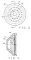
- FIG. 3is a bottom view of a shield cap of the torch head of FIG. 2;
- FIG. 4is a section taken in the plane of line 4 — 4 of FIG. 3;
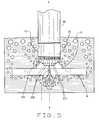
- FIG. 5is a schematic of a plasma arc torch of the present invention cutting a workpiece under water according to a method of the present invention
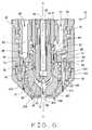
- FIG. 6is a fragmented vertical section of a torch head of a second embodiment of a plasma arc torch of the present invention.
- FIG. 7is a bottom view of a shield cap of the torch head of FIG. 6.
- FIG. 8is a section taken in the plane of line 8 — 8 of FIG. 7 .
- a torch head of a plasma arc torch of the present invention for cutting a workpiece under wateris generally indicated at 31 .
- the torchis a dual gas type torch in which both a primary working gas and a secondary gas or fluid are utilized.
- the torch head 31includes a cathode 33 having an upper end (not shown) secured in a torch body 32 (a portion of which is shown in FIG. 2) of the torch, and an electrode 35 electrically connected to the cathode.
- the cathode 33 and electrode 35are arranged in coaxial relationship with each other about a longitudinal axis X of the torch.
- the electrode 33 of the illustrated embodimentis constructed of copper, and has an insert 51 of emissive material (e.g., hafnium) secured in a recess 53 in the bottom of the electrode.
- a central insulator 47(a portion of which is shown in the drawing) constructed of a suitable electrically insulating material surrounds a substantial portion of the cathode 33 to electrically isolate the cathode from a generally tubular anode 49 that surrounds the insulator.
- a cooling tube 41extends longitudinally within a central bore 43 of the cathode 33 down into a central bore 45 of the electrode 35 .
- the cooling tube 41is in fluid communication with a source (not shown) of cooling water to receive cooling water into the tube and direct the water down into the electrode bore 45 .
- the cooling waterflows out from the cooling tube 41 generally at the bottom of the tube to cool the electrode 35 , particularly in the area of the emissive insert 51 .
- the waterthen flows upward within the electrode bore 45 and cathode bore 43 and outward therefrom for cooling other components of the torch prior to being exhausted from the torch.
- the anode 49has a pair of intake ports 57 , 59 for separately receiving a primary working gas and a secondary gas. More particularly, the primary gas intake port 57 is in fluid communication with a source (not shown) of working gas for receiving the primary working gas into the torch head 3 1 , and the secondary gas intake port 59 is in fluid communication with a source (not shown) of secondary gas for receiving secondary gas into the torch head.
- the primary gasis pure oxygen and the secondary gas is compressed air, free of oil impurities.
- Primary and secondary channels, indicated as 61 and 63respectively, extend down through the anode 49 from the corresponding intake ports 57 , 59 to direct the primary working gas and secondary gas down through the anode.
- the first channel 61leads to an annular inner plenum 65 formed between the anode 49 and the outer surfaces of the central insulator 47 and a gas distributor 67 .
- the second channel 63leads to an annular outer plenum 69 which is separate from the inner plenum 65 and defined by the anode 49 and the inner surface of a shield body 71 surrounding the anode.
- a lower end 73 of the anode 49includes longitudinally extending bores 75 in fluid communication with the outer plenum 69 to direct secondary gas out from the lower end of the anode.
- a metal tip 77also commonly referred to as a nozzle, is disposed in the torch head 31 surrounding a lower portion of the electrode 35 in radially and longitudinally spaced relationship therewith to form a primary gas passage 79 (otherwise referred to as an arc chamber or plasma chamber) between the tip and the electrode.
- An inlet passage 81 defined by the electrode 35 and a lower portion of the generally tubular gas distributor 67extends longitudinally within the torch head 31 in radially spaced relationship with the electrode.
- the inlet passage 81is in fluid communication with the primary gas passage 79 for directing primary gas into the primary gas passage.
- An upper end 83 of the tip 77extends up between the anode 49 and the gas distributor 67 for threaded connection with the anode in radially spaced relationship with the gas distributor to define a passage 85 in fluid communication with the inner plenum 65 and extending down from the inner plenum to the lower portion of the gas distributor. Openings 87 in the lower portion of the gas distributor 67 are in fluid communication with the passage 85 extending down from the inner plenum 65 of the anode 49 to direct primary working gas in the inner plenum to flow into the inlet passage 81 and then down through the primary gas passage 79 .
- the openings 87 in the gas distributor 67are formed generally tangentially thereto for causing a swirling action of the primary gas flowing into and down through the primary gas passage 79 .
- a portion of the primary gas passage 79 generally along the bottom of the insert 51defines an arc region in which a plasma arc attaches to the electrode during operation of the torch.
- a central exit orifice 89 of the tip 77is in fluid communication with the primary gas passage 79 such that primary gas exits the tip in the form of an ionized plasma, or plasma arc, and is directed down against the workpiece.
- the shield body 71 surrounding the anode 49is constructed of a heat insulating material and has internal threads 91 for threaded engagement with corresponding external threads 93 on the anode to secure the shield body on the anode.
- An insert 95 constructed of a heat insulating materialis secured to the shield body 71 .
- the insert 95 of the illustrated embodimentis integrally formed with the shield body 71 .
- the insert 95may be formed separately from the shield body 71 and connected thereto, as by threaded connection, without departing from the scope of this invention.
- a shield cap 101 of the present inventionsurrounds the torch tip 77 in longitudinally and radially spaced relationship therewith and is threadably connected to the insert 95 to secure the shield cap on the torch head 31 .
- the shield cap 101 shown in FIG. 2has a cylindrical upper wall 102 at the upper end of the shield cap having internal threads 104 for threaded connection with the insert 95 , a generally conical side wall 106 extending downward and inward from the upper wall toward the longitudinal axis X of the torch, and a front face or wall 108 at the bottom of the shield cap extending generally at a right angle to the longitudinal axis of the torch.
- the side wall 106 of the shield cap 101may instead be cylindrical, and may further be of the same outer diameter as the upper wall 102 so that the side wall and upper wall are in flush alignment, without departing from the scope of this invention.
- a central opening 103 in the shield cap 101is coaxially aligned with the central exit orifice 89 of the tip 77 on the longitudinal axis X of the torch to define a central exit opening of the torch through which the plasma arc exits the torch and is directed onto the workpiece.
- Longitudinally extending bores 105 in the insert 95are in fluid communication with the bores 75 in the lower end 73 of the anode 49 so that secondary gas flowing through the anode is further directed down through the bores in the shield cap insert into a secondary gas passage 107 formed between the inner surface of the shield cap 101 and the tip 77 as well as between the shield cap and a portion of the insert.
- the secondary gas passage 107extends from the bores 105 of the insert 95 to the central opening 103 of the shield cap 101 for exhausting secondary gas from the torch head 31 and directing the secondary gas to impinge on the plasma arc as the arc and secondary gas exit the torch head through the central opening.
- a first set of secondary openings 109are provided in the side wall 108 of the shield cap 101 , with each such opening having a central axis extending generally at an angle relative to the longitudinal axis X of the torch.
- the openings 109are positioned in generally radially spaced relationship with the longitudinal axis X of the torch a distance D 1 (FIG. 4) to define a first set of secondary exit openings of the torch.
- the openings 109are spaced equidistant from each other about the longitudinal axis X and the central opening 103 , forming a concentric inner ring of openings about the central opening of the shield cap 101 .
- These secondary openings 109are in fluid communication with the secondary gas passage 107 upstream of the central opening 103 of the shield cap 101 to exhaust a portion of secondary gas from the torch head 31 as the gas flows through the secondary gas passage toward the central opening of the shield cap.
- the centers of the openings 109 of the illustrated embodimentare spaced radially a distance D 1 of 0.328 inches from the longitudinal axis X of the torch. It is understood this distance may vary. However, the distance is preferably at least about 0.265 inches, more preferably within a range of about 0.265 inches to about 0.328 inches and most preferably about 0.328 inches to space the openings 109 from the longitudinal axis X a distance sufficient to reduce the risk that secondary gas exiting the openings will destabilize the plasma arc exiting the central opening 103 of the shield cap 101 .
- the orientation of the secondary openings 109directs secondary gas exhausted from the torch generally toward the workpiece in spaced relationship with the plasma arc and the longitudinal axis X of the torch.
- each of the secondary openings 109is angled outward relative to the longitudinal axis X of the torch at an angle in the range of about 0°-15°, and is more preferably about 15°.
- the openings 109may alternatively be disposed in the front wall 108 of the shield cap 101 and remain within the scope of this invention.
- a second set of secondary openings 111is provided in the conical side wall 106 of the shield cap 101 , with each such opening having a central axis extending generally parallel to the longitudinal axis X of the torch.
- the openings 111are spaced generally radially from the longitudinal axis X a distance D 2 (FIG. 4) greater than the distance D 1 of the first set of secondary openings 109 from the longitudinal axis to define a second set of secondary exit openings of the torch.
- the openings 111may alternatively be disposed in the front wall 108 of the shield cap 101 and remain within the scope of this invention.
- This second set of openings 111is also in fluid communication with the secondary gas passage 107 to further exhaust an additional portion of secondary gas from the torch toward the workpiece as the secondary gas flows through the secondary gas passage to the central opening 103 of the shield cap 101 .
- these secondary openings 111are spaced equidistant from each other about the central opening 103 , forming a second concentric outer ring of openings about the central opening of the shield cap 101 .
- the centers of the openings 111are spaced a distance D 2 from the longitudinal axis a distance of at least about 0.375 inches, more preferably in the range of about 0.375 inches to about 0.5 inches, and most preferably about 0.481 inches.
- the relative number and size of the secondary openings 109 , 111 in the front wall 108 of the shield cap 101are a function of the desired flow rate of secondary gas exhausted from the torch through the openings relative to a desired flow rate of the remaining secondary gas to be exhausted from torch through the central opening 103 of the shield cap.
- the flow rate of secondary gas exhausted from the torch through the first and second sets of secondary openings 109 , 111 of the shield cap 101is substantially greater than the flow rate of secondary gas exhausted from the torch through the central opening 103 .
- the ratio defined by the flow rate of secondary gas exhausted from the secondary openings 109 , 111 relative to the flow rate of secondary gas exhausted from the central opening 103 of the shield cap 101is preferably at least 5:1, and more preferably is in the range of about 15:1 to 20:1.
- the first set of secondary openings 109includes twelve such openings, each having a diameter of about 0.047 inches.
- the second set of secondary openings 111includes twenty-four such openings, with each opening also having a diameter of about 0.047 inches.
- the diameter of the central opening 103 of the shield cap 101is approximately 0.219 inches.
- an optimal secondary gas flow rate through the first and second sets of secondary openings 109 , 111is in the range of about 150 scfh (standard cubic feet per hour) to about 400 scfh, and is more preferably about 285 scfh, with a flow rate of secondary gas through the central opening 103 of the shield cap 101 being in the range of about 10 scfh to about 20 scfh, and more preferably about 15 scfh.
- a workpiece Wis submerged under water and the torch is oriented generally downward with the torch head 31 also under water in close proximity to the workpiece.
- Primary working gassuch as pure oxygen
- Primary working gasis pumped from the source of working gas into the torch and flows through a primary gas flow path (indicated by single shaft arrows in FIG. 2) comprising the anode primary intake port 57 , anode channel 61 , inner plenum 65 , passage 85 , gas distributor openings 87 , inlet passage 81 , primary gas passage 79 , tip orifice 89 , and the central opening 103 of the shield cap 101 .
- Primary gas in the primary gas passage 79flows down through the arc region and out through the exit orifice 89 of the tip 77 and central opening 103 of the shield cap 101 in the form of an ionized plasma I.
- Secondary gassuch as compressed air
- a secondary gas flow path(indicated by double shaft arrows in FIG. 2) comprising the secondary gas intake port 59 , anode channel 63 , outer plenum 69 , the longitudinally extending bores 75 in the lower end 73 of the anode, the bores 105 in the insert 95 , the secondary gas passage 107 , the first and second sets of secondary openings 109 , 111 in the shield cap 101 and the central opening 103 of the shield cap.
- a substantial portion of the secondary gasis exhausted from the torch via the first and second sets of secondary openings 109 , 111 in the shield cap 111 .
- the orientation of the openings 109 , 111directs the secondary gas down generally toward the workpiece W. Secondary gas exits the torch at a sufficiently high flow rate to displace water surrounding the plasma arc. An air pocket P is thus formed beneath the shield cap 101 surrounding the central opening 103 of the shield cap to shield the plasma flow I exiting the central opening of the shield cap against contact by the water. The remaining portion of secondary gas flows through the secondary gas passage 107 toward the central opening 103 of the shield cap 101 , communicating with the primary gas flow path to impinge upon the plasma arc as the ionized plasma exits the torch through the central opening of the shield cap.
- gassuch as either the primary working gas or the secondary gas
- gasmay be directed generally toward the workpiece W from external of the torch, such as by a collar (not shown) circumscribing the torch head 31 in fluid communication with the source of working gas or the source of secondary gas and having openings for directing the gas generally toward the workpiece W in radially spaced relationship with the central axis of the torch, without departing from the scope of this invention.
- FIGS. 6-8illustrate a second embodiment of a plasma torch of the present invention similar to the first embodiment of FIGS. 2-4 but with a first set of secondary openings 209 provided in the front wall 108 of the shield cap 101 .
- Each of the openings 209has a central axis extending generally parallel to the longitudinal axis X of the torch.
- the openings 209are positioned in generally radially spaced relationship with the longitudinal axis X of the torch a distance D 1 (FIG. 8) to define the first set of secondary exit openings of the torch.
- the openings 209are spaced equidistant from each other about the longitudinal axis X and the central opening 103 , forming a concentric inner ring of openings about the central opening of the shield cap 101 .
- These secondary openings 209are in fluid communication with the secondary gas passage 107 upstream of the central opening 103 of the shield cap 101 to exhaust a portion of secondary gas from the torch head 31 as the gas flows through the secondary gas passage toward the central opening of the shield cap.
- the centers of the openings 209 of the illustrated embodimentare spaced radially a distance D 1 of 0.256 inches from the longitudinal axis X of the torch. It is understood this distance may vary. However, as discussed with respect to the openings 109 of the first embodiment, the distance D 1 is preferably at least about 0.265 inches and more preferably within a range of about 0.265 inches to about 0.328 inches to space the openings 209 from the longitudinal axis X a distance sufficient to reduce the risk that secondary gas exiting the openings will destabilize the plasma arc exiting the central opening 103 of the shield cap 101 .
- the longitudinal orientation of the secondary openings 209directs secondary gas exhausted from the torch toward the workpiece in a direction generally parallel to the plasma arc and the longitudinal axis X of the torch.
- the openings 209may alternatively be disposed in the side wall 106 of the shield cap 101 and remain within the scope of this invention.
- the high flow rate of secondary gas exhausted through the secondary openings 109 , 111displaces water beneath the shield cap 101 , creating an air pocket P beneath the shield cap and surrounding the plasma arc I to reduce the quenching effect of water on the cutting arc. Since the workpiece W remains in the water, the advantages of cutting under water, such as reduced noise, glare and smoke, are still achieved.
- directing the secondary gas flow from two sets of secondary openings 109 , 111 in a direction generally toward the work piece, with the second set of secondary openings spaced radially outward from the longitudinal axis X a distance greater than the radial spacing of the first set of secondary openings,allows secondary gas to exit the secondary openings close enough to the central opening 103 of the shield cap 101 to form an air pocket P surrounding the arc, but far enough away so as to reduce the risk of destabilizing the plasma arc.
Landscapes
- Engineering & Computer Science (AREA)
- Physics & Mathematics (AREA)
- Plasma & Fusion (AREA)
- Spectroscopy & Molecular Physics (AREA)
- Mechanical Engineering (AREA)
- Plasma Technology (AREA)
- Arc Welding In General (AREA)
Abstract
Description
Claims (36)
Priority Applications (4)
| Application Number | Priority Date | Filing Date | Title |
|---|---|---|---|
| US09/693,480US6498316B1 (en) | 1999-10-25 | 2000-10-20 | Plasma torch and method for underwater cutting |
| CA002389437ACA2389437A1 (en) | 1999-10-25 | 2000-10-24 | Plasma torch and method for underwater cutting |
| EP00992478AEP1224846A2 (en) | 1999-10-25 | 2000-10-24 | Plasma torch and method for underwater cutting |
| MXPA02004095AMXPA02004095A (en) | 1999-10-25 | 2000-10-24 | Plasma torch and method for underwater cutting. |
Applications Claiming Priority (2)
| Application Number | Priority Date | Filing Date | Title |
|---|---|---|---|
| US16139899P | 1999-10-25 | 1999-10-25 | |
| US09/693,480US6498316B1 (en) | 1999-10-25 | 2000-10-20 | Plasma torch and method for underwater cutting |
Publications (1)
| Publication Number | Publication Date |
|---|---|
| US6498316B1true US6498316B1 (en) | 2002-12-24 |
Family
ID=22581027
Family Applications (1)
| Application Number | Title | Priority Date | Filing Date |
|---|---|---|---|
| US09/693,480Expired - LifetimeUS6498316B1 (en) | 1999-10-25 | 2000-10-20 | Plasma torch and method for underwater cutting |
Country Status (6)
| Country | Link |
|---|---|
| US (1) | US6498316B1 (en) |
| EP (1) | EP1224846A2 (en) |
| AU (1) | AU4503601A (en) |
| CA (1) | CA2389437A1 (en) |
| MX (1) | MXPA02004095A (en) |
| WO (1) | WO2001038035A2 (en) |
Cited By (12)
| Publication number | Priority date | Publication date | Assignee | Title |
|---|---|---|---|---|
| US20030173339A1 (en)* | 2000-06-21 | 2003-09-18 | Fryer Paul Chalfont | High temperature tooling |
| US20080083708A1 (en)* | 2006-08-25 | 2008-04-10 | Thermal Dynamics Corporation | Contoured shield orifice for a plasma arc torch |
| CZ301742B6 (en)* | 2003-02-27 | 2010-06-09 | Thermal Dynamics Corporation | Vented shield system for plasma arc torch and method of operating thereof |
| US20140144892A1 (en)* | 2007-09-04 | 2014-05-29 | Thermal Dynamics Corporation | Hybrid shield device for a plasma arc torch |
| US20140273796A1 (en)* | 2013-03-14 | 2014-09-18 | General Electric Company | Synthetic jet driven cooling device with increased volumetric flow |
| US20140291303A1 (en)* | 2012-03-23 | 2014-10-02 | Manfred Hollberg | Plasma electrode for a plasma arc torch with replaceable electrode tip |
| US20150028002A1 (en)* | 2013-07-25 | 2015-01-29 | Hypertherm, Inc. | Devices for Gas Cooling Plasma Arc Torches and Related Systems and Methods |
| US20150376759A1 (en)* | 2013-01-04 | 2015-12-31 | Ford Global Technologies Llc | Device for thermally coating a surface |
| US20170182584A1 (en)* | 2015-01-30 | 2017-06-29 | Komatsu Industries Corporation | Insulation guide for plasma torch, and replacement part unit |
| RU2655430C1 (en)* | 2016-04-11 | 2018-05-28 | Гипертерм, Инк. | Plasma-arc cutting system, including fixing capacitors and other consumable components and related working methods |
| US10917961B2 (en)* | 2017-09-13 | 2021-02-09 | Lincoln Global, Inc. | High temperature isolating insert for plasma cutting torch |
| US11622440B2 (en)* | 2014-05-30 | 2023-04-04 | Hypertherm, Inc. | Cooling plasma cutting system consumables and related systems and methods |
Families Citing this family (1)
| Publication number | Priority date | Publication date | Assignee | Title |
|---|---|---|---|---|
| CZ35530U1 (en)* | 2021-01-15 | 2021-11-16 | B&Bartoni, spol. s r.o. | Plasma torch nozzle protection shield |
Citations (29)
| Publication number | Priority date | Publication date | Assignee | Title |
|---|---|---|---|---|
| US3832513A (en) | 1973-04-09 | 1974-08-27 | G Klasson | Starting and stabilizing apparatus for a gas-tungsten arc welding system |
| US4024373A (en) | 1974-06-20 | 1977-05-17 | David Grigorievich Bykhovsky | Apparatus for plasma working of electrically-conductive materials and method of operating same |
| US4029930A (en) | 1972-09-04 | 1977-06-14 | Mitsubishi Jukogyo Kabushiki Kaisha | Welding torch for underwater welding |
| US4273982A (en) | 1976-05-19 | 1981-06-16 | Arcair Company | Underwater cutting and gouging method |
| US4291217A (en) | 1978-09-30 | 1981-09-22 | Messer Griesheim | Process for underwater plasma cutting of workpieces |
| US4361748A (en) | 1981-01-30 | 1982-11-30 | Couch Jr Richard W | Cooling and height sensing system for a plasma arc cutting tool |
| US4382170A (en) | 1980-08-30 | 1983-05-03 | Trumpf Gmbh & Co. | Thermal cutting jet device with suction apparatus |
| US4389559A (en) | 1981-01-28 | 1983-06-21 | Eutectic Corporation | Plasma-transferred-arc torch construction |
| US4390772A (en) | 1978-09-28 | 1983-06-28 | Susumu Hiratake | Plasma torch and a method of producing a plasma |
| US4421970A (en) | 1981-01-30 | 1983-12-20 | Hypertherm, Incorporated | Height sensing system for a plasma arc cutting tool |
| US4625094A (en) | 1982-10-01 | 1986-11-25 | L'air Liquide, Societe Anonyme Pour L'etude Et L'exploitation Des Procedes Georges Claude | Plasma torches |
| US4701590A (en) | 1986-04-17 | 1987-10-20 | Thermal Dynamics Corporation | Spring loaded electrode exposure interlock device |
| US4716269A (en) | 1986-10-01 | 1987-12-29 | L-Tec Company | Plasma arc torch having supplemental electrode cooling mechanisms |
| US4743734A (en) | 1985-04-25 | 1988-05-10 | N P K Za Kontrolno Zavarachni Raboti | Nozzle for plasma arc torch |
| US4816637A (en) | 1985-11-25 | 1989-03-28 | Hypertherm, Inc. | Underwater and above-water plasma arc cutting torch and method |
| US4861962A (en) | 1988-06-07 | 1989-08-29 | Hypertherm, Inc. | Nozzle shield for a plasma arc torch |
| US4902871A (en) | 1987-01-30 | 1990-02-20 | Hypertherm, Inc. | Apparatus and process for cooling a plasma arc electrode |
| US5109150A (en) | 1987-03-24 | 1992-04-28 | The United States Of America As Represented By The Secretary Of The Navy | Open-arc plasma wire spray method and apparatus |
| US5120930A (en) | 1988-06-07 | 1992-06-09 | Hypertherm, Inc. | Plasma arc torch with improved nozzle shield and step flow |
| US5132512A (en) | 1988-06-07 | 1992-07-21 | Hypertherm, Inc. | Arc torch nozzle shield for plasma |
| US5194715A (en) | 1991-11-27 | 1993-03-16 | Esab Welding Products, Inc. | Plasma arc torch used in underwater cutting |
| US5216221A (en) | 1992-01-17 | 1993-06-01 | Esab Welding Products, Inc. | Plasma arc torch power disabling mechanism |
| US5278388A (en) | 1993-06-07 | 1994-01-11 | Huang Huang Nan | Plasma welding and cutting gun for discharging plasma gas with constant outlet pressure |
| US5302804A (en) | 1993-06-25 | 1994-04-12 | The United States Of America As Represented By The Administrator Of The National Aeronautics And Space Administration | Gas arc constriction for plasma arc welding |
| FR2703557A1 (en) | 1993-03-29 | 1994-10-07 | Soudure Autogene Francaise | Plasma torch and method of implementation for gouging parts. |
| US5660743A (en) | 1995-06-05 | 1997-08-26 | The Esab Group, Inc. | Plasma arc torch having water injection nozzle assembly |
| EP0794697A2 (en) | 1991-04-12 | 1997-09-10 | Hypertherm, Inc. | Plasma arc cutting apparatus |
| US5695662A (en)* | 1988-06-07 | 1997-12-09 | Hypertherm, Inc. | Plasma arc cutting process and apparatus using an oxygen-rich gas shield |
| US6265689B1 (en)* | 2000-04-24 | 2001-07-24 | General Electric Company | Method of underwater cladding using a powder-fan plasma torch |
- 2000
- 2000-10-20USUS09/693,480patent/US6498316B1/ennot_activeExpired - Lifetime
- 2000-10-24AUAU45036/01Apatent/AU4503601A/ennot_activeAbandoned
- 2000-10-24WOPCT/US2000/041499patent/WO2001038035A2/ennot_activeApplication Discontinuation
- 2000-10-24CACA002389437Apatent/CA2389437A1/ennot_activeAbandoned
- 2000-10-24MXMXPA02004095Apatent/MXPA02004095A/ennot_activeApplication Discontinuation
- 2000-10-24EPEP00992478Apatent/EP1224846A2/ennot_activeWithdrawn
Patent Citations (30)
| Publication number | Priority date | Publication date | Assignee | Title |
|---|---|---|---|---|
| US4029930A (en) | 1972-09-04 | 1977-06-14 | Mitsubishi Jukogyo Kabushiki Kaisha | Welding torch for underwater welding |
| US3832513A (en) | 1973-04-09 | 1974-08-27 | G Klasson | Starting and stabilizing apparatus for a gas-tungsten arc welding system |
| US4024373A (en) | 1974-06-20 | 1977-05-17 | David Grigorievich Bykhovsky | Apparatus for plasma working of electrically-conductive materials and method of operating same |
| US4273982A (en) | 1976-05-19 | 1981-06-16 | Arcair Company | Underwater cutting and gouging method |
| US4390772A (en) | 1978-09-28 | 1983-06-28 | Susumu Hiratake | Plasma torch and a method of producing a plasma |
| US4291217A (en) | 1978-09-30 | 1981-09-22 | Messer Griesheim | Process for underwater plasma cutting of workpieces |
| US4382170A (en) | 1980-08-30 | 1983-05-03 | Trumpf Gmbh & Co. | Thermal cutting jet device with suction apparatus |
| US4389559A (en) | 1981-01-28 | 1983-06-21 | Eutectic Corporation | Plasma-transferred-arc torch construction |
| US4361748A (en) | 1981-01-30 | 1982-11-30 | Couch Jr Richard W | Cooling and height sensing system for a plasma arc cutting tool |
| US4421970A (en) | 1981-01-30 | 1983-12-20 | Hypertherm, Incorporated | Height sensing system for a plasma arc cutting tool |
| US4625094A (en) | 1982-10-01 | 1986-11-25 | L'air Liquide, Societe Anonyme Pour L'etude Et L'exploitation Des Procedes Georges Claude | Plasma torches |
| US4743734A (en) | 1985-04-25 | 1988-05-10 | N P K Za Kontrolno Zavarachni Raboti | Nozzle for plasma arc torch |
| US4816637A (en) | 1985-11-25 | 1989-03-28 | Hypertherm, Inc. | Underwater and above-water plasma arc cutting torch and method |
| US4701590A (en) | 1986-04-17 | 1987-10-20 | Thermal Dynamics Corporation | Spring loaded electrode exposure interlock device |
| US4716269A (en) | 1986-10-01 | 1987-12-29 | L-Tec Company | Plasma arc torch having supplemental electrode cooling mechanisms |
| US4902871A (en) | 1987-01-30 | 1990-02-20 | Hypertherm, Inc. | Apparatus and process for cooling a plasma arc electrode |
| US5109150A (en) | 1987-03-24 | 1992-04-28 | The United States Of America As Represented By The Secretary Of The Navy | Open-arc plasma wire spray method and apparatus |
| US4861962B1 (en) | 1988-06-07 | 1996-07-16 | Hypertherm Inc | Nozzle shield for a plasma arc torch |
| US5120930A (en) | 1988-06-07 | 1992-06-09 | Hypertherm, Inc. | Plasma arc torch with improved nozzle shield and step flow |
| US5132512A (en) | 1988-06-07 | 1992-07-21 | Hypertherm, Inc. | Arc torch nozzle shield for plasma |
| US4861962A (en) | 1988-06-07 | 1989-08-29 | Hypertherm, Inc. | Nozzle shield for a plasma arc torch |
| US5695662A (en)* | 1988-06-07 | 1997-12-09 | Hypertherm, Inc. | Plasma arc cutting process and apparatus using an oxygen-rich gas shield |
| EP0794697A2 (en) | 1991-04-12 | 1997-09-10 | Hypertherm, Inc. | Plasma arc cutting apparatus |
| US5194715A (en) | 1991-11-27 | 1993-03-16 | Esab Welding Products, Inc. | Plasma arc torch used in underwater cutting |
| US5216221A (en) | 1992-01-17 | 1993-06-01 | Esab Welding Products, Inc. | Plasma arc torch power disabling mechanism |
| FR2703557A1 (en) | 1993-03-29 | 1994-10-07 | Soudure Autogene Francaise | Plasma torch and method of implementation for gouging parts. |
| US5278388A (en) | 1993-06-07 | 1994-01-11 | Huang Huang Nan | Plasma welding and cutting gun for discharging plasma gas with constant outlet pressure |
| US5302804A (en) | 1993-06-25 | 1994-04-12 | The United States Of America As Represented By The Administrator Of The National Aeronautics And Space Administration | Gas arc constriction for plasma arc welding |
| US5660743A (en) | 1995-06-05 | 1997-08-26 | The Esab Group, Inc. | Plasma arc torch having water injection nozzle assembly |
| US6265689B1 (en)* | 2000-04-24 | 2001-07-24 | General Electric Company | Method of underwater cladding using a powder-fan plasma torch |
Non-Patent Citations (1)
| Title |
|---|
| International Search Report in Application No. PCT/US 00/41499 dated Oct. 9, 2001. |
Cited By (22)
| Publication number | Priority date | Publication date | Assignee | Title |
|---|---|---|---|---|
| US20030173339A1 (en)* | 2000-06-21 | 2003-09-18 | Fryer Paul Chalfont | High temperature tooling |
| CZ301742B6 (en)* | 2003-02-27 | 2010-06-09 | Thermal Dynamics Corporation | Vented shield system for plasma arc torch and method of operating thereof |
| US20080083708A1 (en)* | 2006-08-25 | 2008-04-10 | Thermal Dynamics Corporation | Contoured shield orifice for a plasma arc torch |
| US7737383B2 (en)* | 2006-08-25 | 2010-06-15 | Thermal Dynamics Corporation | Contoured shield orifice for a plasma arc torch |
| US9210787B2 (en)* | 2007-09-04 | 2015-12-08 | Victor Equipment Company | Hybrid shield device for a plasma arc torch |
| US20140144892A1 (en)* | 2007-09-04 | 2014-05-29 | Thermal Dynamics Corporation | Hybrid shield device for a plasma arc torch |
| US20140291303A1 (en)* | 2012-03-23 | 2014-10-02 | Manfred Hollberg | Plasma electrode for a plasma arc torch with replaceable electrode tip |
| US9736916B2 (en)* | 2012-03-23 | 2017-08-15 | Manfred Hollberg | Plasma electrode for a plasma arc torch with replaceable electrode tip |
| US10060020B2 (en)* | 2013-01-04 | 2018-08-28 | Ford Global Technologies, Llc | Device for thermally coating a surface |
| US20150376759A1 (en)* | 2013-01-04 | 2015-12-31 | Ford Global Technologies Llc | Device for thermally coating a surface |
| US9976762B2 (en)* | 2013-03-14 | 2018-05-22 | General Electric Company | Synthetic jet driven cooling device with increased volumetric flow |
| US20140273796A1 (en)* | 2013-03-14 | 2014-09-18 | General Electric Company | Synthetic jet driven cooling device with increased volumetric flow |
| US20150028002A1 (en)* | 2013-07-25 | 2015-01-29 | Hypertherm, Inc. | Devices for Gas Cooling Plasma Arc Torches and Related Systems and Methods |
| US9144148B2 (en) | 2013-07-25 | 2015-09-22 | Hypertherm, Inc. | Devices for gas cooling plasma arc torches and related systems and methods |
| US10716199B2 (en)* | 2013-07-25 | 2020-07-14 | Hypertherm, Inc. | Devices for gas cooling plasma arc torches and related systems and methods |
| US11622440B2 (en)* | 2014-05-30 | 2023-04-04 | Hypertherm, Inc. | Cooling plasma cutting system consumables and related systems and methods |
| US20170182584A1 (en)* | 2015-01-30 | 2017-06-29 | Komatsu Industries Corporation | Insulation guide for plasma torch, and replacement part unit |
| US10625364B2 (en)* | 2015-01-30 | 2020-04-21 | Komatsu Industries Corporation | Insulation guide for plasma torch, and replacement part unit |
| RU2655430C1 (en)* | 2016-04-11 | 2018-05-28 | Гипертерм, Инк. | Plasma-arc cutting system, including fixing capacitors and other consumable components and related working methods |
| US10492286B2 (en) | 2016-04-11 | 2019-11-26 | Hypertherm, Inc. | Plasma arc cutting system, including retaining caps, and other consumables, and related operational methods |
| US10716200B2 (en) | 2016-04-11 | 2020-07-14 | Hypertherm, Inc. | Plasma arc cutting system, including retaining caps, and other consumables, and related operational methods |
| US10917961B2 (en)* | 2017-09-13 | 2021-02-09 | Lincoln Global, Inc. | High temperature isolating insert for plasma cutting torch |
Also Published As
| Publication number | Publication date |
|---|---|
| WO2001038035A9 (en) | 2002-08-15 |
| AU4503601A (en) | 2001-06-04 |
| WO2001038035A2 (en) | 2001-05-31 |
| EP1224846A2 (en) | 2002-07-24 |
| MXPA02004095A (en) | 2002-11-29 |
| WO2001038035A3 (en) | 2002-02-21 |
| CA2389437A1 (en) | 2001-05-31 |
Similar Documents
| Publication | Publication Date | Title |
|---|---|---|
| US6337460B2 (en) | Plasma arc torch and method for cutting a workpiece | |
| CA2174019C (en) | Plasma arc torch having water injection nozzle assembly | |
| CN101084701B (en) | Plasma arc welding torch with an electrode with internal channels | |
| US7375303B2 (en) | Plasma arc torch having an electrode with internal passages | |
| US5756959A (en) | Coolant tube for use in a liquid-cooled electrode disposed in a plasma arc torch | |
| KR930005953B1 (en) | How to start improved plasma arc torch | |
| US5747767A (en) | Extended water-injection nozzle assembly with improved centering | |
| CA2024861C (en) | Plasma arc cutting torch having extended lower nozzle member | |
| US4748312A (en) | Plasma-arc torch with gas cooled blow-out electrode | |
| US6498316B1 (en) | Plasma torch and method for underwater cutting | |
| US5124525A (en) | Plasma arc torch having improved nozzle assembly | |
| EP1576862B1 (en) | Plasma gas distributor and method of distributing a plasma gas | |
| AU670291B2 (en) | Improved electrode for high current density plasma arc torch | |
| US5194715A (en) | Plasma arc torch used in underwater cutting | |
| US6069339A (en) | Dual flow nozzle shield for plasma-arc torch | |
| JPH0533520B2 (en) | ||
| US6096992A (en) | Low current water injection nozzle and associated method | |
| CN210010578U (en) | Plasma arc cutting torch | |
| CN114535765A (en) | Plasma arc cutting torch | |
| JP2002103075A (en) | Laser / plasma combined processing equipment |
Legal Events
| Date | Code | Title | Description |
|---|---|---|---|
| AS | Assignment | Owner name:THERMAL DYNAMICS CORPORATION, NEW HAMPSHIRE Free format text:ASSIGNMENT OF ASSIGNORS INTEREST;ASSIGNORS:AHER, BARRY;HORNER-RICHARDSON, KEVIN;HEWETT, ROGER;REEL/FRAME:011302/0243 Effective date:20001020 | |
| STCF | Information on status: patent grant | Free format text:PATENTED CASE | |
| AS | Assignment | Owner name:GENERAL ELECTRIC CAPITAL CORPORATION, AS AGENT, CO Free format text:SECURITY INTEREST;ASSIGNOR:THERMAL DYNAMICS CORPORATION;REEL/FRAME:014102/0405 Effective date:20030523 | |
| AS | Assignment | Owner name:DEUTSCHE BANK TRUST COMPANY AMERICAS CORPORATE TRU Free format text:ASSIGNMENT OF ASSIGNORS INTEREST;ASSIGNOR:THERMAL DYNAMICS CORPORATION;REEL/FRAME:013699/0038 Effective date:20030523 | |
| AS | Assignment | Owner name:THERMAL DYNAMICS CORPORATION, MISSOURI Free format text:RELEASE OF SECURITY AGREEMENT;ASSIGNOR:DEUTSCHE BANK TRUST COMPANY AMERICAS;REEL/FRAME:015105/0936 Effective date:20040205 | |
| FPAY | Fee payment | Year of fee payment:4 | |
| SULP | Surcharge for late payment | ||
| AS | Assignment | Owner name:REGIONS BANK, GEORGIA Free format text:PATENT SECURITY AGREEMENT;ASSIGNOR:THERMAL DYNAMICS CORPORATION;REEL/FRAME:023163/0056 Effective date:20090814 Owner name:REGIONS BANK,GEORGIA Free format text:PATENT SECURITY AGREEMENT;ASSIGNOR:THERMAL DYNAMICS CORPORATION;REEL/FRAME:023163/0056 Effective date:20090814 | |
| FPAY | Fee payment | Year of fee payment:8 | |
| AS | Assignment | Owner name:THERMAL DYNAMICS CORPORATION, MISSOURI Free format text:RELEASE BY SECURED PARTY;ASSIGNOR:REGIONS BANK;REEL/FRAME:025039/0367 Effective date:20100630 | |
| AS | Assignment | Owner name:U.S. BANK NATIONAL ASSOCIATION, AS COLLATERAL TRUS Free format text:SECURITY AGREEMENT;ASSIGNOR:THERMAL DYNAMICS CORPORATION;REEL/FRAME:025441/0313 Effective date:20101203 | |
| AS | Assignment | Owner name:GENERAL ELECTRIC CAPITAL CORPORATION, AS AGENT, CO Free format text:SECURITY AGREEMENT;ASSIGNOR:THERMAL DYNAMICS CORPORATION;REEL/FRAME:025451/0613 Effective date:20101203 | |
| FPAY | Fee payment | Year of fee payment:12 | |
| AS | Assignment | Owner name:VICTOR TECHNOLOGIES GROUP, INC., MISSOURI Free format text:RELEASE OF SECURITY INTEREST;ASSIGNOR:U.S BANK, NATIONAL ASSOCIATION;REEL/FRAME:033370/0775 Effective date:20140414 | |
| AS | Assignment | Owner name:STOODY COMPANY, MISSOURI Free format text:RELEASE OF SECURITY INTEREST;ASSIGNOR:GENERAL ELECTRIC CAPITAL CORPORATION;REEL/FRAME:033421/0785 Effective date:20140414 Owner name:THERMAL DYNAMICS CORPORATION, MISSOURI Free format text:RELEASE OF SECURITY INTEREST;ASSIGNOR:GENERAL ELECTRIC CAPITAL CORPORATION;REEL/FRAME:033421/0785 Effective date:20140414 Owner name:VICTOR EQUIPMENT COMPANY, NEW JERSEY Free format text:RELEASE OF SECURITY INTEREST;ASSIGNOR:GENERAL ELECTRIC CAPITAL CORPORATION;REEL/FRAME:033421/0785 Effective date:20140414 | |
| AS | Assignment | Owner name:DEUTSCHE BANK AG NEW YORK BRANCH, NEW YORK Free format text:SECURITY INTEREST;ASSIGNORS:VICTOR TECHNOLOGIES INTERNATIONAL INC.;VICTOR EQUIPMENT COMPANY;THERMAL DYNAMICS CORPORATION;AND OTHERS;REEL/FRAME:033831/0404 Effective date:20140813 | |
| AS | Assignment | Owner name:DISTRIBUTION MINING & EQUIPMENT COMPANY, LLC, DELAWARE Free format text:RELEASE BY SECURED PARTY;ASSIGNOR:DEUTSCHE BANK AG NEW YORK BRANCH;REEL/FRAME:035903/0051 Effective date:20150605 Owner name:IMO INDUSTRIES INC., DELAWARE Free format text:RELEASE BY SECURED PARTY;ASSIGNOR:DEUTSCHE BANK AG NEW YORK BRANCH;REEL/FRAME:035903/0051 Effective date:20150605 Owner name:ANDERSON GROUP INC., SOUTH CAROLINA Free format text:RELEASE BY SECURED PARTY;ASSIGNOR:DEUTSCHE BANK AG NEW YORK BRANCH;REEL/FRAME:035903/0051 Effective date:20150605 Owner name:HOWDEN NORTH AMERICA INC., SOUTH CAROLINA Free format text:RELEASE BY SECURED PARTY;ASSIGNOR:DEUTSCHE BANK AG NEW YORK BRANCH;REEL/FRAME:035903/0051 Effective date:20150605 Owner name:SHAWEBONE HOLDINGS INC., SOUTH CAROLINA Free format text:RELEASE BY SECURED PARTY;ASSIGNOR:DEUTSCHE BANK AG NEW YORK BRANCH;REEL/FRAME:035903/0051 Effective date:20150605 Owner name:HOWDEN GROUP LIMITED, SCOTLAND Free format text:RELEASE BY SECURED PARTY;ASSIGNOR:DEUTSCHE BANK AG NEW YORK BRANCH;REEL/FRAME:035903/0051 Effective date:20150605 Owner name:ALLOY RODS GLOBAL INC., DELAWARE Free format text:RELEASE BY SECURED PARTY;ASSIGNOR:DEUTSCHE BANK AG NEW YORK BRANCH;REEL/FRAME:035903/0051 Effective date:20150605 Owner name:STOODY COMPANY, MISSOURI Free format text:RELEASE BY SECURED PARTY;ASSIGNOR:DEUTSCHE BANK AG NEW YORK BRANCH;REEL/FRAME:035903/0051 Effective date:20150605 Owner name:EMSA HOLDINGS INC., SOUTH CAROLINA Free format text:RELEASE BY SECURED PARTY;ASSIGNOR:DEUTSCHE BANK AG NEW YORK BRANCH;REEL/FRAME:035903/0051 Effective date:20150605 Owner name:CONSTELLATION PUMPS CORPORATION, DELAWARE Free format text:RELEASE BY SECURED PARTY;ASSIGNOR:DEUTSCHE BANK AG NEW YORK BRANCH;REEL/FRAME:035903/0051 Effective date:20150605 Owner name:ALCOTEC WIRE CORPORATION, MICHIGAN Free format text:RELEASE BY SECURED PARTY;ASSIGNOR:DEUTSCHE BANK AG NEW YORK BRANCH;REEL/FRAME:035903/0051 Effective date:20150605 Owner name:CLARUS FLUID INTELLIGENCE, LLC, WASHINGTON Free format text:RELEASE BY SECURED PARTY;ASSIGNOR:DEUTSCHE BANK AG NEW YORK BRANCH;REEL/FRAME:035903/0051 Effective date:20150605 Owner name:DISTRIBUTION MINING & EQUIPMENT COMPANY, LLC, DELA Free format text:RELEASE BY SECURED PARTY;ASSIGNOR:DEUTSCHE BANK AG NEW YORK BRANCH;REEL/FRAME:035903/0051 Effective date:20150605 Owner name:COLFAX CORPORATION, MARYLAND Free format text:RELEASE BY SECURED PARTY;ASSIGNOR:DEUTSCHE BANK AG NEW YORK BRANCH;REEL/FRAME:035903/0051 Effective date:20150605 Owner name:HOWDEN COMPRESSORS, INC., SOUTH CAROLINA Free format text:RELEASE BY SECURED PARTY;ASSIGNOR:DEUTSCHE BANK AG NEW YORK BRANCH;REEL/FRAME:035903/0051 Effective date:20150605 Owner name:ESAB AB, SWEDEN Free format text:RELEASE BY SECURED PARTY;ASSIGNOR:DEUTSCHE BANK AG NEW YORK BRANCH;REEL/FRAME:035903/0051 Effective date:20150605 Owner name:THE ESAB GROUP INC., SOUTH CAROLINA Free format text:RELEASE BY SECURED PARTY;ASSIGNOR:DEUTSCHE BANK AG NEW YORK BRANCH;REEL/FRAME:035903/0051 Effective date:20150605 Owner name:TOTAL LUBRICATION MANAGEMENT COMPANY, TEXAS Free format text:RELEASE BY SECURED PARTY;ASSIGNOR:DEUTSCHE BANK AG NEW YORK BRANCH;REEL/FRAME:035903/0051 Effective date:20150605 Owner name:HOWDEN AMERICAN FAN COMPANY, SOUTH CAROLINA Free format text:RELEASE BY SECURED PARTY;ASSIGNOR:DEUTSCHE BANK AG NEW YORK BRANCH;REEL/FRAME:035903/0051 Effective date:20150605 Owner name:VICTOR EQUIPMENT COMPANY, MISSOURI Free format text:RELEASE BY SECURED PARTY;ASSIGNOR:DEUTSCHE BANK AG NEW YORK BRANCH;REEL/FRAME:035903/0051 Effective date:20150605 Owner name:VICTOR TECHNOLOGIES INTERNATIONAL, INC., MISSOURI Free format text:RELEASE BY SECURED PARTY;ASSIGNOR:DEUTSCHE BANK AG NEW YORK BRANCH;REEL/FRAME:035903/0051 Effective date:20150605 | |
| AS | Assignment | Owner name:VICTOR EQUIPMENT COMPANY, MISSOURI Free format text:MERGER;ASSIGNOR:THERMAL DYNAMICS CORPORATION;REEL/FRAME:037711/0952 Effective date:20141219 |