US6497975B2 - Direct methanol fuel cell including integrated flow field and method of fabrication - Google Patents
Direct methanol fuel cell including integrated flow field and method of fabricationDownload PDFInfo
- Publication number
- US6497975B2 US6497975B2US09/738,126US73812600AUS6497975B2US 6497975 B2US6497975 B2US 6497975B2US 73812600 AUS73812600 AUS 73812600AUS 6497975 B2US6497975 B2US 6497975B2
- Authority
- US
- United States
- Prior art keywords
- fuel cell
- fuel
- base portion
- membrane electrode
- cell membrane
- Prior art date
- Legal status (The legal status is an assumption and is not a legal conclusion. Google has not performed a legal analysis and makes no representation as to the accuracy of the status listed.)
- Expired - Lifetime, expires
Links
Images

Classifications
- H—ELECTRICITY
- H01—ELECTRIC ELEMENTS
- H01M—PROCESSES OR MEANS, e.g. BATTERIES, FOR THE DIRECT CONVERSION OF CHEMICAL ENERGY INTO ELECTRICAL ENERGY
- H01M8/00—Fuel cells; Manufacture thereof
- H01M8/10—Fuel cells with solid electrolytes
- H01M8/1009—Fuel cells with solid electrolytes with one of the reactants being liquid, solid or liquid-charged
- H—ELECTRICITY
- H01—ELECTRIC ELEMENTS
- H01M—PROCESSES OR MEANS, e.g. BATTERIES, FOR THE DIRECT CONVERSION OF CHEMICAL ENERGY INTO ELECTRICAL ENERGY
- H01M8/00—Fuel cells; Manufacture thereof
- H01M8/24—Grouping of fuel cells, e.g. stacking of fuel cells
- H01M8/2404—Processes or apparatus for grouping fuel cells
- H—ELECTRICITY
- H01—ELECTRIC ELEMENTS
- H01M—PROCESSES OR MEANS, e.g. BATTERIES, FOR THE DIRECT CONVERSION OF CHEMICAL ENERGY INTO ELECTRICAL ENERGY
- H01M8/00—Fuel cells; Manufacture thereof
- H01M8/24—Grouping of fuel cells, e.g. stacking of fuel cells
- H01M8/241—Grouping of fuel cells, e.g. stacking of fuel cells with solid or matrix-supported electrolytes
- H01M8/2418—Grouping by arranging unit cells in a plane
- H—ELECTRICITY
- H01—ELECTRIC ELEMENTS
- H01M—PROCESSES OR MEANS, e.g. BATTERIES, FOR THE DIRECT CONVERSION OF CHEMICAL ENERGY INTO ELECTRICAL ENERGY
- H01M2300/00—Electrolytes
- H01M2300/0017—Non-aqueous electrolytes
- H01M2300/0065—Solid electrolytes
- H01M2300/0082—Organic polymers
- H—ELECTRICITY
- H01—ELECTRIC ELEMENTS
- H01M—PROCESSES OR MEANS, e.g. BATTERIES, FOR THE DIRECT CONVERSION OF CHEMICAL ENERGY INTO ELECTRICAL ENERGY
- H01M8/00—Fuel cells; Manufacture thereof
- H01M8/04—Auxiliary arrangements, e.g. for control of pressure or for circulation of fluids
- H01M8/04082—Arrangements for control of reactant parameters, e.g. pressure or concentration
- H01M8/04089—Arrangements for control of reactant parameters, e.g. pressure or concentration of gaseous reactants
- H01M8/04119—Arrangements for control of reactant parameters, e.g. pressure or concentration of gaseous reactants with simultaneous supply or evacuation of electrolyte; Humidifying or dehumidifying
- H01M8/04156—Arrangements for control of reactant parameters, e.g. pressure or concentration of gaseous reactants with simultaneous supply or evacuation of electrolyte; Humidifying or dehumidifying with product water removal
- H—ELECTRICITY
- H01—ELECTRIC ELEMENTS
- H01M—PROCESSES OR MEANS, e.g. BATTERIES, FOR THE DIRECT CONVERSION OF CHEMICAL ENERGY INTO ELECTRICAL ENERGY
- H01M8/00—Fuel cells; Manufacture thereof
- H01M8/04—Auxiliary arrangements, e.g. for control of pressure or for circulation of fluids
- H01M8/04082—Arrangements for control of reactant parameters, e.g. pressure or concentration
- H01M8/04186—Arrangements for control of reactant parameters, e.g. pressure or concentration of liquid-charged or electrolyte-charged reactants
- Y—GENERAL TAGGING OF NEW TECHNOLOGICAL DEVELOPMENTS; GENERAL TAGGING OF CROSS-SECTIONAL TECHNOLOGIES SPANNING OVER SEVERAL SECTIONS OF THE IPC; TECHNICAL SUBJECTS COVERED BY FORMER USPC CROSS-REFERENCE ART COLLECTIONS [XRACs] AND DIGESTS
- Y02—TECHNOLOGIES OR APPLICATIONS FOR MITIGATION OR ADAPTATION AGAINST CLIMATE CHANGE
- Y02E—REDUCTION OF GREENHOUSE GAS [GHG] EMISSIONS, RELATED TO ENERGY GENERATION, TRANSMISSION OR DISTRIBUTION
- Y02E60/00—Enabling technologies; Technologies with a potential or indirect contribution to GHG emissions mitigation
- Y02E60/30—Hydrogen technology
- Y02E60/50—Fuel cells
Definitions
- the present inventionpertains to fuel cells, and more particularly to a direct methanol fuel cell including an integrated fuel flow field and a method of fabricating the device, in which even distribution of the fuel into the fuel cell is achieved during the process of generating electrical energy.
- Fuel cells in generalare “battery replacements”, and like batteries, produce electricity through an electrochemical process without combustion.
- the electrochemical process utilizedprovides for the combining of protons with oxygen from air or as a pure gas.
- the processis accomplished utilizing a proton exchange membrane (PEM) sandwiched between two electrodes, namely an anode and a cathode.
- PEMproton exchange membrane
- Fuel cellsas known, are a perpetual provider of electricity.
- Hydrogenis typically used as the fuel for producing the electricity and can be processed from methanol, natural gas, petroleum, or stored as pure hydrogen.
- Direct methanol fuel cellsutilize methanol, in a gaseous or liquid form as fuel, thus eliminating the need for expensive reforming operations.
- DMFCsprovide for a simpler PEM cell system, lower weight, streamlined production, and thus lower costs.
- a dilute aqueous solution of methanolis fed as the fuel on the anode side (first electrode) and the cathode side (second electrode) is exposed to forced or ambient air (or 02).
- a Nafion® type proton conducting membranetypically separates the anode and the cathode sides.
- DMFC designsare large stacks with forced airflow operating at elevated temperatures of approximately 60-80° C. Smaller air breathing DMFC designs require the miniaturization of all the system components and are thus more complicated.
- stack connectionsare made between the fuel cell assemblies with conductive plates, having channels or grooves for gas distribution formed therein.
- a typical conventional fuel cellis comprised of an anode (H 2 or methanol side) current collector, anode backing, membrane electrode assembly (MEA) (anode/ion conducting membrane/cathode), cathode backing, and cathode current collector.
- MEAmembrane electrode assembly
- Typical open circuit voltage under load for a direct methanol fuel cellis approximately in the range of 0.3-0.5 V
- fuel cellsare typically stacked in series (bi-polar manner—positive to negative) one on top of another, or by connecting different cells in series in a planar arrangement.
- Conventional fuel cellscan also be stacked in parallel (positive to positive) to obtain higher current, but generally, larger active areas are simply used instead.
- a dilute aqueous methanol (usually 3-4% methanol) solutionis used as the fuel on the anode side. If the methanol concentration is too high, then there is a methanol crossover problem that will reduce the efficiency of the fuel cell. If the methanol concentration is too low then there will not be enough fuel on the anode side for the fuel cell reaction to take place.
- Current DMFC designsare for larger stacks with forced airflow. The smaller air breathing DMFC designs are difficult to accomplish because of the complexity in miniaturizing all the required system components and integrating them in a small unit required for portable applications.
- the fuel flowwill follow the path of least resistance to the fuel cell. This path of least resistance results in uneven distribution of the fuel to the anode.
- carbon dioxide by-productscan accumulate in areas and prevent fuel from accessing the anode, or electrocatalyst. This results in back pressure which is formed due to the lack of means for exhausting of the carbon dioxide.
- MEAmembrane electrode assembly
- a fuel cell device and method of forming the fuel cell deviceincluding a base portion, formed of a singular body, and having a major surface. At least one membrane electrode assembly is formed on the major surface of the base portion.
- the base portionincludes an integrated fuel flow field for the equal distribution of fuel to the membrane electrode assembly.
- a fluid supply channelis defined in the base portion and communicating with the fuel flow field and the at least one membrane electrode assembly for supplying a fuel-bearing fluid to the at least one membrane electrode assembly.
- An exhaust channelis defined in the base portion and communicating with the at least one membrane electrode assembly. The exhaust channel is spaced apart from the fluid supply channel for exhausting by-product fluid, including water, from the at least one membrane electrode assembly.
- the membrane electrode assembly and the cooperating fluid supply channel and cooperating exhaust channelforming a single fuel cell assembly.
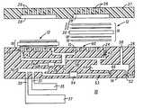
- FIG. 1is a simplified sectional view of a plurality of direct methanol fuel cell devices including an integrated fuel flow field formed on a single base portion including a plurality of microfluidic channels, according to the present invention
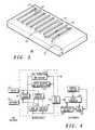
- FIG. 2is a simplified exploded orthogonal view of the flow field ceramic layers, according to the present invention.
- FIG. 3is a simplified orthogonal view, illustrating the fuel flow field according to the present invention.
- FIG. 4is a simplified schematic diagram illustrating the fuel cell device an integrated fuel flow field of the present invention.
- a flow fieldIn fuel cells, a flow field is typically machined or designed in an electrically conductive material, usually graphite or stainless steel. When forming a fuel cell on a ceramic substrate, the flow field can be designed and fabricated to include microchannels for fluidic communication and a conductive paste printed for current collection.
- a serpentine patternis the most common type used in graphite or stainless steel fuel cells. With multilayer ceramic technology, a serpentine pattern can be fabricated, but only to a certain frequency between the channels. When the channels become too close together, the processing becomes very difficult. In order to get the channels closer to each other ( ⁇ 40 mils) a three-dimensional pattern can be utilized.
- FIG. 1illustrates in simplified sectional view a direct methanol fuel cell including an integrated flow field fabricated according to the present invention. Illustrated is a fuel cell system, generally referenced 10 , including a plurality of fuel cell assemblies 12 . Fuel cell assemblies 12 are formed on a base portion. Base portion 14 is designed to be impermeable to the fuel and oxidizer materials that are utilized to power fuel cells 12 . Typically a hydrogen-containing fuel is utilized to power fuel cells 12 . Suitable fuels that are consumed by fuel cells 12 to produce electrical energy are hydrogen-containing materials such as hydrogen, methane and methanol. In this particular example, an aqueous solution of methanol is used as the fuel for fuel cells 12 .
- Base portion 14is typically formed of glass, plastic, silicon, graphite, ceramic, or any other suitable material.
- planar stack 10is composed of a plurality of direct methanol fuel cells 12 each defined by a fuel cell membrane electrode assembly (MEA) (discussed presently).
- MEAfuel cell membrane electrode assembly
- Base portion 14has formed within a plurality of micro-fluidic channels as illustrated. More particularly, base portion 14 has formed a first fluid inlet 30 and a second fluid inlet 31 , in fluidic communication with a fluid supply channel 32 .
- Fluid supply channel 32is formed in base portion 14 utilizing standard techniques, well known in the art, such as multi-layer ceramic technology, micro-machining, or injection molding. Fluid supply channel 32 supplies a fuel-bearing fluid 34 to fuel cell 12 .
- fuel-bearing fluid 34is comprised of methanol and water being delivered directly from a methanol tank 35 and a water tank 37 .
- a mixing chamber 36is formed in base portion 14 in micro-fluidic communication with fluid supply channel 32 as illustrated.
- fuel-bearing fluid 34is preferably 0.5%-4.0% methanol in water (99.5%-96.0%).
- the goalis to pump methanol into the overall assembly 10 at a rate of approximately 0.002 ml/min and pump the water into the assembly 10 at a rate of approximately 0.098 ml/min (2% to 98%).
- the fuel cell assembly 10would also be able to use other fuels, such as hydrogen or ethanol, but it should be noted that ethanol is not as efficient, nor does it produce as much power as does the use of methanol.
- a separate methanol tank 35 and water tank 37are utilized to supply the fuel-bearing fluid 34 .
- the methanolwill be pumped in at a given rate, and the water will be added as needed determined by the efficiency of the integrated water management system (discussed presently), which is monitored by a methanol concentration sensor 39 .
- Methanol concentration sensor 39helps maintain the methanol ratio in the mixture.
- the methanol and waterwill be homogeneously mixed in mixing chamber 36 before equally flowing to fuel cells 12 .
- an exhaust channel 38communicating with fuel cells 12 .
- Exhaust channel 38serves to remove exhaust products 42 from fuel cell 12 , namely carbon dioxide and a water/methanol mixture.
- exhaust productsare separated in a carbon dioxide separation chamber 44 into the water/methanol mixture 46 and a carbon dioxide gas 48 .
- gas 48is expelled through an exhaust outlet 52 , such as a gas permeable membrane and water/methanol mixture 46 is recirculated through a recirculating channel 53 , having included as a part thereof a pump 54 , such as a MEMs-type pump, or check valve type assembly, back to mixing chamber 36 .
- microfluidic communicationin microfluidic communication is a water management system and a water recovery return channel 58 .
- the water management systemserves to recapture water from the cathode side of fuel cell 12 , and direct it toward water recovery return channel 58 , as illustrated.
- Water recovery return channel 58is in micro-fluidic communication with separation chamber 44 and ultimately mixing chamber 36 .
- the fuel delivery systemincludes methanol and water, in the form of methanol tank 35 and water tank 37 , which is to be carried in portable disposable cartridge-like devices, connected through tubing to the base portion 14 .
- Fuel cell 12is comprised of a fuel cell membrane electrode assembly 16 comprised of first electrode 18 , or anode, including a carbon cloth backing 19 , a film 20 , such as a protonically conducting electrolyte membrane, and a second electrode 22 , or cathode, including a carbon cloth backing 23 .
- First and second electrodes 18 and 22are comprised of any metal material, including those selected from the group consisting of platinum, palladium, gold, nickel, tungsten, ruthenium, molybdenum, osmium, iridium, copper, cobalt, iron, and alloys of platinum, palladium, gold, nickel, tungsten, molybdenum, osmium, iridium, copper, cobalt, iron, and ruthenium.
- Other components that may be contained in electrodes 18 and 22are protonically conductive polymer, electrically conductive polymer, and inorganic supports such as carbon and metal oxides.
- Film 20is further described as formed of a Nafion® type material that prevents the permeation of fuel from the anode side (first electrode 18 ) to the cathode side (second electrode 22 ) of each fuel cell 12 .
- Membrane electrode assemblies 16are positioned in a recess 24 formed in an uppermost major surface 26 of a base portion 14 . It is anticipated by this disclosure that membrane electrode assemblies 16 can be positioned on major surface 26 of base portion 14 without the need for the formation of recess 24 . In this instance, a spacer (not shown) would be utilized to avoid complete compression of membrane electrode assembly 16 .
- Base portion 14further includes a current collector 15 .
- Planar stack array 10further includes a top portion, more specifically, in this particular embodiment, a current collector 28 , including a plurality of air flow-throughs 29 positioned to overlay membrane electrode assembly 16 .
- Current collector 28is formed as part of a cap portion, generally referenced 27 .
- Cap portion 27provides for the exposure of second electrode 22 to ambient air.
- fuel cell membrane electrode assembly 16is formed using a hot press method, or other standard method known in the art. More particularly, first electrode 18 is formed or positioned in contact with base portion 14 . Various materials are suitable for the formation of electrode 18 as previously described. In this specific embodiment, and for exemplary purposes, first electrode 18 has a dimension of approximately 2.0 cm ⁇ 2.0 cm.
- Film 20formed of a protonically conducting electrolyte, also referred to as a proton exchange membrane (PEM), is comprised of a Nafion® type material. Film 20 as previously stated serves to limit the permeation of fuel from the anode 18 of each fuel cell 12 to the cathode 22 of each fuel cells 12 .
- PEMproton exchange membrane
- a second electrode 22is formed to be correspondingly cooperating with first electrode 18 .
- Second electrode 22is formed having approximately the same dimension as its corresponding first electrode 18 .
- each fuel cell membrane electrode assembly 16is comprised of first electrode 18 , film 20 , second electrode 22 , and gas diffusion media layers, or more particularly carbon cloth backing layers, 19 and 23 .
- current collector 28is positioned relative to second electrode 22 .
- Current collector 28is formed at least 0.1 mm thick and of a length dependent upon a point of contact on each fuel cell 12 .
- the plurality of fuel cells 12can be electrically interfaced using silver conducting paint deposited by evaporation or sputtering.
- fuel cells 12can be electrically interfaced utilizing either a series connection or a parallel connection, dependent upon the desired resultant voltage. As illustrated in FIG. 1, further included in fuel cell device 10 is the integration of a three-dimensional flow field, generally referenced 60 (discussed presently).
- fuel cell array 10has formed as a part thereof, four individual fuel cells 12 , having an overall base portion 14 dimension of approximately 5.5 cm ⁇ 5.5 cm ⁇ 0.5 cm, and individual fuel cell 12 area of 4 ⁇ 1.5-2.0 cm squares. Each individual fuel cell 12 is capable of generating approximately 0.5 V and 22.5 mA/cm of power. Fuel cells 12 are formed on a base portion 14 , each fuel cell 12 being spaced at least 0.5-1 mm apart from an adjacent fuel cell 12 . It should be understood that dependent upon the required power output, any number of fuel cells 12 and any measurement of distance between fuel cells, can be fabricated to form a planar array of fuel cells, from one single fuel cell, to numerous fuel cells, as illustrated in FIG. 1 .
- Three-dimensional flow field 60is comprised of a plurality of ceramic layers, generally referenced 62 , 64 , and 66 , having formed therein a plurality of three-dimensional microfluidic fuel delivery channels (discussed presently). It should be understood that layers 62 , 64 , and 66 are included as a portion of the ceramic layers, that make up multi-layer ceramic fuel cell device 10 of the present invention and that additional layers where needed may be included to further define flow field 60 .
- a first ceramic layer 62is formed having a fluid inlet 68 for the inlet of fuel 34 from fluid supply channel 32 and a fluid outlet 69 for the exhaust of spent fuel components to exhaust channel 38 .
- Fuel inlet 68 and fuel outlet 69are in fluidic communication with a ceramic layer 64 , having formed therein a plurality of flow returns 70 (described presently) for the three-dimensional flow of fuel 34 through the multi-layers of ceramic.
- a third ceramic layer 66includes a plurality of fuel delivery channels 72 , further defining flow field 60 . It is anticipated that fuel delivery channels 72 are fabricated having a separation between adjoining channels 72 of less than 1000 mils, and having a preferred spacing of approximately 40 mils between adjoining channels 72 .
- the flow of fuel(as illustrated by arrows 34 ) follows flow field 60 along fuel delivery channels 72 .
- the fuel flow 34flows through a flow return 70 , initially in a direction opposite adjacent electrode 18 , as illustrated in FIG. 1 .
- Fuel flow 34flows within flow return 70 until it is returned up to the next fuel delivery channel 72 .
- Fuel flow 34is thus defined as flowing within the plurality of fuel delivery channels 72 in a single direction path as illustrated by arrows 34 . This single direction path aids in the forcing out of carbon dioxide that is produced by electrode assembly 16 as an exhaust by-product.
- carbon dioxide produced at the electrode assembly 16is forced back into flow field 60 , or more particularly into fuel delivery channels 72 . Due to the single direction path of fuel flow 34 within fuel delivery channels 72 , this exhaust carbon dioxide is forced out of fuel delivery channels 72 through fuel outlet 69 toward exhaust channel 38 .
- flow field 60provides for the fabrication of a plurality of fuel delivery channels 72 in closer proximity to each other than has previously been realized. This in turn provides for enhanced fuel distribution to fuel cells 12 , a diminished diffusion span of fuel 34 across gas diffusion layer 19 , and provides for improved carbon dioxide removal as previously described.
- Fuel delivery channels 72are fabricated sufficiently close to each other, more particularly, with less than 125 mils separation, and preferably with less than 40 mils separation between adjoining channels, so that fuel 34 is able to reach the entire surface of the adjacent anode 18 by diffusion through the gas diffusion layer, or more specifically carbon cloth, 19 .
- FIG. 4illustrated is a simplified schematic diagram detailing the system of the present invention. Illustrated are methanol tank 35 and water tank 37 in microfluidic communication with mixing chamber 36 .
- Mixing chamber 36serves to achieve the proper ratio of methanol to water.
- the fuel-bearing fluidflows through the fluid supply channel toward the fuel cell 12 .
- An optional MEMs-type pump 40is utilized to assist with this flow.
- Concentration sensors 39are provided to assist with monitoring the methanol concentration, and the temperature of the fuel-bearing fluid.
- the fuel-bearing fluidnext reaches fuel cell stack 12 and generates power.
- the poweris supplied to a DC—DC converter 80 which converts the generated voltage to a useable voltage for powering a portable electronic device, such as a cell phone 82 and included as a part thereof a rechargeable battery 84 .
- a portable electronic devicesuch as a cell phone 82 and included as a part thereof a rechargeable battery 84 .
- spent fluidis exhausted through the exhaust channel toward a carbon dioxide separation chamber and carbon dioxide vent, generally referenced 44 .
- wateris recovered from the cathode side of the fuel cell 12 , and from the separation chamber 44 and is recirculated through a recirculating channel back to the mixing chamber 36 . This recirculating of fluid provides for the consumption of less water from water tank 37 and thus less replenishment of water tank 37 .
- a fuel cell systemincluding an integrated fuel flow field and method of fabrication which provides for the fabrication of the system, providing for inclusion of a single fuel cell or a plurality of fuel cells to be formed on a planar surface, thus allowing higher voltages and currents to be gained on a single planar surface.
- the designprovides for a simplified system in which fuel is delivered to the anode side of the electrode assembly through a three-dimensional fuel flow field, thus providing for even distribution to the anode and thus enhanced performance.
- the system of the present inventionis a semi-self contained system, and is not orientation sensitive, thus providing for ease in moving the system, such as when providing power to a portable electronic device.
Landscapes
- Life Sciences & Earth Sciences (AREA)
- Engineering & Computer Science (AREA)
- Manufacturing & Machinery (AREA)
- Sustainable Development (AREA)
- Sustainable Energy (AREA)
- Chemical & Material Sciences (AREA)
- Chemical Kinetics & Catalysis (AREA)
- Electrochemistry (AREA)
- General Chemical & Material Sciences (AREA)
- Fuel Cell (AREA)
Abstract
Description
Claims (18)
Priority Applications (6)
| Application Number | Priority Date | Filing Date | Title |
|---|---|---|---|
| US09/738,126US6497975B2 (en) | 2000-12-15 | 2000-12-15 | Direct methanol fuel cell including integrated flow field and method of fabrication |
| CNB018205429ACN100438182C (en) | 2000-12-15 | 2001-11-19 | Direct methanol fuel cell including integrated flow field |
| AU2002241510AAU2002241510A1 (en) | 2000-12-15 | 2001-11-19 | Direct methanol fuel cell including integrated flow field |
| PCT/US2001/044052WO2002049138A2 (en) | 2000-12-15 | 2001-11-19 | Direct methanol fuel cell including integrated flow field |
| JP2002550340AJP4284068B2 (en) | 2000-12-15 | 2001-11-19 | Direct methanol fuel cell system with built-in flow field |
| TW090129664ATW527746B (en) | 2000-12-15 | 2001-11-30 | Direct methanol fuel cell including integrated flow field and method of fabrication |
Applications Claiming Priority (1)
| Application Number | Priority Date | Filing Date | Title |
|---|---|---|---|
| US09/738,126US6497975B2 (en) | 2000-12-15 | 2000-12-15 | Direct methanol fuel cell including integrated flow field and method of fabrication |
Publications (2)
| Publication Number | Publication Date |
|---|---|
| US20020076598A1 US20020076598A1 (en) | 2002-06-20 |
| US6497975B2true US6497975B2 (en) | 2002-12-24 |
Family
ID=24966684
Family Applications (1)
| Application Number | Title | Priority Date | Filing Date |
|---|---|---|---|
| US09/738,126Expired - LifetimeUS6497975B2 (en) | 2000-12-15 | 2000-12-15 | Direct methanol fuel cell including integrated flow field and method of fabrication |
Country Status (6)
| Country | Link |
|---|---|
| US (1) | US6497975B2 (en) |
| JP (1) | JP4284068B2 (en) |
| CN (1) | CN100438182C (en) |
| AU (1) | AU2002241510A1 (en) |
| TW (1) | TW527746B (en) |
| WO (1) | WO2002049138A2 (en) |
Cited By (36)
| Publication number | Priority date | Publication date | Assignee | Title |
|---|---|---|---|---|
| US20020182479A1 (en)* | 2001-05-15 | 2002-12-05 | Mallari Jonathan C. | Fuel cell electrode pair assemblies and related methods |
| US20030031907A1 (en)* | 2001-05-15 | 2003-02-13 | Shimson Gottesfeld | Methods and apparatuses for a pressure driven fuel cell system |
| WO2003071627A1 (en)* | 2002-02-19 | 2003-08-28 | Mti Microfuel Cells, Inc. | Simplified direct oxidation fuel cell system |
| US6660423B2 (en)* | 2000-12-15 | 2003-12-09 | Motorola, Inc. | Direct methanol fuel cell including a water management system and method of fabrication |
| US6696189B2 (en)* | 2000-12-15 | 2004-02-24 | Motorola, Inc. | Direct methanol fuel cell system including an integrated methanol sensor and method of fabrication |
| US6727016B2 (en)* | 2001-08-09 | 2004-04-27 | Motorola, Inc. | Direct methanol fuel cell including a water recovery and re-circulation system and method of fabrication |
| US20040209136A1 (en)* | 2003-04-15 | 2004-10-21 | Xiaoming Ren | Direct oxidation fuel cell operating with direct feed of concentrated fuel under passive water management |
| US20040211054A1 (en)* | 2002-04-24 | 2004-10-28 | Morse Jeffrey D. | Microfluidic systems with embedded materials and structures and method thereof |
| US20040215375A1 (en)* | 2003-04-22 | 2004-10-28 | Joan Andre | Flight control indicator for an aircraft, in particular a transport airplane, intended to supply the thrust generated by at least one engine of the aircraft |
| US20040224207A1 (en)* | 2001-09-25 | 2004-11-11 | Hitachi, Ltd. | Fuel cell power generation equipment and a device using the same |
| US20050026016A1 (en)* | 2003-07-28 | 2005-02-03 | Kearl Daniel A. | Fuel cell with integral manifold |
| US20050053823A1 (en)* | 2003-09-05 | 2005-03-10 | Cho Hye-Jung | Fuel supply device for direct mathanol fuel cells |
| US20050170227A1 (en)* | 2001-03-27 | 2005-08-04 | Corey John A. | Methods and apparatuses for managing effluent products in a fuel cell system |
| US7160637B2 (en) | 2003-05-27 | 2007-01-09 | The Regents Of The University Of California | Implantable, miniaturized microbial fuel cell |
| US20070059565A1 (en)* | 2005-09-15 | 2007-03-15 | Billy Siu | Microbial fuel cell with flexible substrate and micro-pillar structure |
| US20070099037A1 (en)* | 2005-11-03 | 2007-05-03 | Ralf Senner | Cascaded stack with gas flow recycle in the first stage |
| US7282293B2 (en) | 2003-04-15 | 2007-10-16 | Mti Microfuel Cells Inc. | Passive water management techniques in direct methanol fuel cells |
| US20080026265A1 (en)* | 2002-01-14 | 2008-01-31 | Markoski Larry J | Electrochemical cells comprising laminar flow induced dynamic conducting interfaces, electronic devices comprising such cells, and methods employing same |
| US20080160388A1 (en)* | 2006-12-27 | 2008-07-03 | Stmicroelectronics S.A. | Package for a miniature fuel cell |
| US20080248343A1 (en)* | 2007-04-02 | 2008-10-09 | Markoski Larry J | Microfluidic fuel cells |
| US20090036303A1 (en)* | 2007-07-30 | 2009-02-05 | Motorola, Inc. | Method of forming a co-fired ceramic apparatus including a micro-reader |
| US20090324998A1 (en)* | 2008-06-30 | 2009-12-31 | Xerox Corporation | Scalable Microbial Fuel Cell and Method of Manufacture |
| US20100035110A1 (en)* | 2006-04-11 | 2010-02-11 | Anders Lundblad | Electrochemical device |
| US20100092838A1 (en)* | 2007-03-12 | 2010-04-15 | Sony Corporation | Fuel cell, electronic device, fuel supply plate, and fuel supply method |
| US20100151344A1 (en)* | 2005-09-30 | 2010-06-17 | Kyocera Corporation | Fuel cell and electronic device including the fuel cell |
| US7807303B2 (en) | 2008-06-30 | 2010-10-05 | Xerox Corporation | Microbial fuel cell and method |
| US7833645B2 (en) | 2005-11-21 | 2010-11-16 | Relion, Inc. | Proton exchange membrane fuel cell and method of forming a fuel cell |
| US20110020723A1 (en)* | 2008-04-04 | 2011-01-27 | Utc Power Corporation | Fuel cell plate having multi-directional flow field |
| US20110151343A1 (en)* | 2006-10-06 | 2011-06-23 | Ryuji Kohno | Fuel cell system |
| US8003274B2 (en) | 2007-10-25 | 2011-08-23 | Relion, Inc. | Direct liquid fuel cell |
| US8026020B2 (en) | 2007-05-08 | 2011-09-27 | Relion, Inc. | Proton exchange membrane fuel cell stack and fuel cell stack module |
| US8119305B2 (en) | 2004-09-15 | 2012-02-21 | Ini Power Systems, Inc. | Electrochemical cells |
| US8158300B2 (en) | 2006-09-19 | 2012-04-17 | Ini Power Systems, Inc. | Permselective composite membrane for electrochemical cells |
| US8163429B2 (en) | 2009-02-05 | 2012-04-24 | Ini Power Systems, Inc. | High efficiency fuel cell system |
| US8551667B2 (en) | 2007-04-17 | 2013-10-08 | Ini Power Systems, Inc. | Hydrogel barrier for fuel cells |
| US9293778B2 (en) | 2007-06-11 | 2016-03-22 | Emergent Power Inc. | Proton exchange membrane fuel cell |
Families Citing this family (37)
| Publication number | Priority date | Publication date | Assignee | Title |
|---|---|---|---|---|
| US6387559B1 (en)* | 2000-07-18 | 2002-05-14 | Motorola, Inc. | Direct methanol fuel cell system and method of fabrication |
| US6465119B1 (en)* | 2000-07-18 | 2002-10-15 | Motorola, Inc. | Fuel cell array apparatus and method of fabrication |
| US20020189947A1 (en)* | 2001-06-13 | 2002-12-19 | Eksigent Technologies Llp | Electroosmotic flow controller |
| US7465382B2 (en)* | 2001-06-13 | 2008-12-16 | Eksigent Technologies Llc | Precision flow control system |
| JP2003072059A (en)* | 2001-06-21 | 2003-03-12 | Ricoh Co Ltd | Ink jet recording device and copier |
| JP2003031240A (en)* | 2001-07-12 | 2003-01-31 | Kemitsukusu:Kk | Small polymer electrolyte fuel cell and fuel cell separator |
| JP3979097B2 (en)* | 2002-01-22 | 2007-09-19 | 日本板硝子株式会社 | Optical element |
| US7393369B2 (en) | 2002-06-11 | 2008-07-01 | Trulite, Inc. | Apparatus, system, and method for generating hydrogen |
| US7235164B2 (en) | 2002-10-18 | 2007-06-26 | Eksigent Technologies, Llc | Electrokinetic pump having capacitive electrodes |
| US7556660B2 (en) | 2003-06-11 | 2009-07-07 | James Kevin Shurtleff | Apparatus and system for promoting a substantially complete reaction of an anhydrous hydride reactant |
| US20050008924A1 (en)* | 2003-06-20 | 2005-01-13 | Sanjiv Malhotra | Compact multi-functional modules for a direct methanol fuel cell system |
| JP4715083B2 (en)* | 2003-09-29 | 2011-07-06 | カシオ計算機株式会社 | Power generation module |
| US7645537B2 (en)* | 2003-10-15 | 2010-01-12 | Hewlett-Packard Development Company, L.P. | Multi-cell fuel cell layer and system |
| US20050162122A1 (en)* | 2004-01-22 | 2005-07-28 | Dunn Glenn M. | Fuel cell power and management system, and technique for controlling and/or operating same |
| US7521140B2 (en)* | 2004-04-19 | 2009-04-21 | Eksigent Technologies, Llc | Fuel cell system with electrokinetic pump |
| JP2006032200A (en)* | 2004-07-20 | 2006-02-02 | Electric Power Dev Co Ltd | Fuel cell |
| JP4503394B2 (en)* | 2004-08-13 | 2010-07-14 | 富士通株式会社 | FUEL CELL SYSTEM, ELECTRIC DEVICE, AND METHOD OF RECOVERING GENERATED WATER IN FUEL CELL SYSTEM |
| DE602005018940D1 (en)* | 2004-08-20 | 2010-03-04 | Hans Peter Naegeli | HYBRID MOTORCYCLE WITH MUSCLE POWER AND ELECTRIC MOTOR DRIVE WITH POWER GENERATED BY A FUEL CELL |
| AU2005304304B2 (en) | 2004-11-12 | 2009-01-15 | Trulite, Inc. | Hydrogen generator cartridge |
| JP5068658B2 (en)* | 2005-09-30 | 2012-11-07 | 京セラ株式会社 | FUEL CELL AND ELECTRONIC DEVICE HAVING THE FUEL CELL |
| KR100646955B1 (en)* | 2005-11-10 | 2006-11-23 | 삼성에스디아이 주식회사 | Fuel cell peripheral driving method and fuel cell system using same |
| DK1957794T3 (en)* | 2005-11-23 | 2014-08-11 | Eksigent Technologies Llc | Electrokinetic pump designs and drug delivery systems |
| US20070264558A1 (en)* | 2006-05-10 | 2007-11-15 | Hsi-Ming Shu | Flow board with capillary flow structure for fuel cell |
| KR100729071B1 (en) | 2006-05-19 | 2007-06-14 | 삼성에스디아이 주식회사 | Fuel supply housing and peripheral module using the same |
| US7648786B2 (en) | 2006-07-27 | 2010-01-19 | Trulite, Inc | System for generating electricity from a chemical hydride |
| US7651542B2 (en) | 2006-07-27 | 2010-01-26 | Thulite, Inc | System for generating hydrogen from a chemical hydride |
| US7867592B2 (en) | 2007-01-30 | 2011-01-11 | Eksigent Technologies, Inc. | Methods, compositions and devices, including electroosmotic pumps, comprising coated porous surfaces |
| JP2008210679A (en)* | 2007-02-27 | 2008-09-11 | Toshiba Corp | Fuel cell |
| US8357214B2 (en) | 2007-04-26 | 2013-01-22 | Trulite, Inc. | Apparatus, system, and method for generating a gas from solid reactant pouches |
| CN101855769A (en) | 2007-07-25 | 2010-10-06 | 特鲁丽特公司 | Apparatus, system, and method to manage the generation and use of hybrid electric power |
| EP2201631B1 (en)* | 2007-08-20 | 2015-05-27 | myFC AB | An arrangement for interconnecting electrochemical cells, a fuel cell assembly and method of manufacturing a fuel cell device |
| WO2009076134A1 (en)* | 2007-12-11 | 2009-06-18 | Eksigent Technologies, Llc | Electrokinetic pump with fixed stroke volume |
| JP2014519570A (en) | 2011-05-05 | 2014-08-14 | エクシジェント テクノロジーズ, エルエルシー | Gel coupling for electrokinetic delivery system |
| US20130115483A1 (en)* | 2011-10-25 | 2013-05-09 | Point Source Power, Inc. | Shield for high-temperature electrochemical device |
| CN109390604B (en)* | 2018-11-30 | 2023-06-20 | 华南理工大学 | A kind of micro channel flow field plate and its preparation method |
| CN109755606B (en)* | 2019-01-21 | 2021-08-10 | 西安交通大学 | A kind of uniform flow field plate fuel cell and its working method |
| CN109860654B (en)* | 2019-01-21 | 2021-10-15 | 西安交通大学 | A material separation and transmission fuel cell and its working method |
Citations (1)
| Publication number | Priority date | Publication date | Assignee | Title |
|---|---|---|---|---|
| US6387559B1 (en)* | 2000-07-18 | 2002-05-14 | Motorola, Inc. | Direct methanol fuel cell system and method of fabrication |
Family Cites Families (4)
| Publication number | Priority date | Publication date | Assignee | Title |
|---|---|---|---|---|
| US3392058A (en)* | 1963-08-27 | 1968-07-09 | Gen Electric | Heat transfer arrangement within a fuel cell structure |
| JPS63110555A (en)* | 1986-10-29 | 1988-05-16 | Hitachi Ltd | Fuel cell stack |
| US5773162A (en)* | 1993-10-12 | 1998-06-30 | California Institute Of Technology | Direct methanol feed fuel cell and system |
| US6465119B1 (en)* | 2000-07-18 | 2002-10-15 | Motorola, Inc. | Fuel cell array apparatus and method of fabrication |
- 2000
- 2000-12-15USUS09/738,126patent/US6497975B2/ennot_activeExpired - Lifetime
- 2001
- 2001-11-19JPJP2002550340Apatent/JP4284068B2/ennot_activeExpired - Fee Related
- 2001-11-19CNCNB018205429Apatent/CN100438182C/ennot_activeExpired - Fee Related
- 2001-11-19AUAU2002241510Apatent/AU2002241510A1/ennot_activeAbandoned
- 2001-11-19WOPCT/US2001/044052patent/WO2002049138A2/ennot_activeCeased
- 2001-11-30TWTW090129664Apatent/TW527746B/ennot_activeIP Right Cessation
Patent Citations (1)
| Publication number | Priority date | Publication date | Assignee | Title |
|---|---|---|---|---|
| US6387559B1 (en)* | 2000-07-18 | 2002-05-14 | Motorola, Inc. | Direct methanol fuel cell system and method of fabrication |
Cited By (66)
| Publication number | Priority date | Publication date | Assignee | Title |
|---|---|---|---|---|
| US6696189B2 (en)* | 2000-12-15 | 2004-02-24 | Motorola, Inc. | Direct methanol fuel cell system including an integrated methanol sensor and method of fabrication |
| US6660423B2 (en)* | 2000-12-15 | 2003-12-09 | Motorola, Inc. | Direct methanol fuel cell including a water management system and method of fabrication |
| US7205059B2 (en) | 2001-03-27 | 2007-04-17 | Mti Microfuel Cells, Inc. | Methods and apparatuses for managing effluent products in a fuel cell system |
| US20050170227A1 (en)* | 2001-03-27 | 2005-08-04 | Corey John A. | Methods and apparatuses for managing effluent products in a fuel cell system |
| US7118822B2 (en)* | 2001-05-15 | 2006-10-10 | Neah Power Systems, Inc. | Fuel cell electrode pair assemblies and related methods |
| US20040076859A1 (en)* | 2001-05-15 | 2004-04-22 | Shimson Gottesfeld | Methods and apparatuses for a pressure driven fuel cell system |
| US20020182479A1 (en)* | 2001-05-15 | 2002-12-05 | Mallari Jonathan C. | Fuel cell electrode pair assemblies and related methods |
| US20030031907A1 (en)* | 2001-05-15 | 2003-02-13 | Shimson Gottesfeld | Methods and apparatuses for a pressure driven fuel cell system |
| US6811916B2 (en)* | 2001-05-15 | 2004-11-02 | Neah Power Systems, Inc. | Fuel cell electrode pair assemblies and related methods |
| US6686081B2 (en)* | 2001-05-15 | 2004-02-03 | Mti Microfuel Cells, Inc. | Methods and apparatuses for a pressure driven fuel cell system |
| US20050003263A1 (en)* | 2001-05-15 | 2005-01-06 | Mallari Jonathan C. | Fuel cell electrode pair assemblies and related methods |
| US6727016B2 (en)* | 2001-08-09 | 2004-04-27 | Motorola, Inc. | Direct methanol fuel cell including a water recovery and re-circulation system and method of fabrication |
| US20040224207A1 (en)* | 2001-09-25 | 2004-11-11 | Hitachi, Ltd. | Fuel cell power generation equipment and a device using the same |
| US8283090B2 (en)* | 2002-01-14 | 2012-10-09 | The Board Of Trustees Of The University Of Illinois | Electrochemical cells comprising laminar flow induced dynamic conducting interfaces, electronic devices comprising such cells, and methods employing same |
| US20080026265A1 (en)* | 2002-01-14 | 2008-01-31 | Markoski Larry J | Electrochemical cells comprising laminar flow induced dynamic conducting interfaces, electronic devices comprising such cells, and methods employing same |
| WO2003071627A1 (en)* | 2002-02-19 | 2003-08-28 | Mti Microfuel Cells, Inc. | Simplified direct oxidation fuel cell system |
| US20040265680A1 (en)* | 2002-02-19 | 2004-12-30 | Xiaoming Ren | Simplified direct oxidation fuel cell system |
| US20050181271A1 (en)* | 2002-02-19 | 2005-08-18 | Xiaoming Ren | Simplified direct oxidation fuel cell system |
| US6981877B2 (en) | 2002-02-19 | 2006-01-03 | Mti Microfuel Cells Inc. | Simplified direct oxidation fuel cell system |
| US20060068271A1 (en)* | 2002-02-19 | 2006-03-30 | Xiaoming Ren | Simplified direct oxidation fuel cell system |
| US7638215B2 (en) | 2002-02-19 | 2009-12-29 | Mti Microfuel Cells Inc. | Method of controlling delivery of fuel to a direct oxidation fuel cell |
| US7186352B2 (en)* | 2002-04-24 | 2007-03-06 | The Regents Of The University Of California | Microfluidic systems with embedded materials and structures and method thereof |
| US20040211054A1 (en)* | 2002-04-24 | 2004-10-28 | Morse Jeffrey D. | Microfluidic systems with embedded materials and structures and method thereof |
| US7541109B2 (en) | 2003-04-15 | 2009-06-02 | Mti Microfuel Cells, Inc. | Passive water management techniques in direct methanol fuel cells |
| US7407721B2 (en) | 2003-04-15 | 2008-08-05 | Mti Microfuel Cells, Inc. | Direct oxidation fuel cell operating with direct feed of concentrated fuel under passive water management |
| US20080032182A1 (en)* | 2003-04-15 | 2008-02-07 | Mti Microfuel Cells Inc. | Passive water management techniques in direct methanol fuel cells |
| US7282293B2 (en) | 2003-04-15 | 2007-10-16 | Mti Microfuel Cells Inc. | Passive water management techniques in direct methanol fuel cells |
| US20040209136A1 (en)* | 2003-04-15 | 2004-10-21 | Xiaoming Ren | Direct oxidation fuel cell operating with direct feed of concentrated fuel under passive water management |
| US20040215375A1 (en)* | 2003-04-22 | 2004-10-28 | Joan Andre | Flight control indicator for an aircraft, in particular a transport airplane, intended to supply the thrust generated by at least one engine of the aircraft |
| US7160637B2 (en) | 2003-05-27 | 2007-01-09 | The Regents Of The University Of California | Implantable, miniaturized microbial fuel cell |
| US7348087B2 (en) | 2003-07-28 | 2008-03-25 | Hewlett-Packard Development Company, L.P. | Fuel cell with integral manifold |
| US7981560B2 (en) | 2003-07-28 | 2011-07-19 | Eveready Battery Company, Inc. | Fuel cell with integral manifold and laterally spaced electrodes |
| US20100279207A1 (en)* | 2003-07-28 | 2010-11-04 | Kearl Daniel A | Fuel cell with integral manifold |
| US20050026016A1 (en)* | 2003-07-28 | 2005-02-03 | Kearl Daniel A. | Fuel cell with integral manifold |
| US7121308B2 (en) | 2003-09-05 | 2006-10-17 | Samsung Sdi Co., Ltd. | Fuel supply device for direct methanol fuel cells |
| US20050053823A1 (en)* | 2003-09-05 | 2005-03-10 | Cho Hye-Jung | Fuel supply device for direct mathanol fuel cells |
| US8119305B2 (en) | 2004-09-15 | 2012-02-21 | Ini Power Systems, Inc. | Electrochemical cells |
| US20070059565A1 (en)* | 2005-09-15 | 2007-03-15 | Billy Siu | Microbial fuel cell with flexible substrate and micro-pillar structure |
| US7976968B2 (en) | 2005-09-15 | 2011-07-12 | Sweet Power Inc. | Microbial fuel cell with flexible substrate and micro-pillar structure |
| US8481222B2 (en)* | 2005-09-30 | 2013-07-09 | Kyocera Corporation | Fuel cell and electronic device including the fuel cell |
| US20100151344A1 (en)* | 2005-09-30 | 2010-06-17 | Kyocera Corporation | Fuel cell and electronic device including the fuel cell |
| US8007943B2 (en)* | 2005-11-03 | 2011-08-30 | GM Global Technology Operations LLC | Cascaded stack with gas flow recycle in the first stage |
| US20070099037A1 (en)* | 2005-11-03 | 2007-05-03 | Ralf Senner | Cascaded stack with gas flow recycle in the first stage |
| US7833645B2 (en) | 2005-11-21 | 2010-11-16 | Relion, Inc. | Proton exchange membrane fuel cell and method of forming a fuel cell |
| US20100035110A1 (en)* | 2006-04-11 | 2010-02-11 | Anders Lundblad | Electrochemical device |
| US9287570B2 (en)* | 2006-04-11 | 2016-03-15 | Myfc Ab | Planar configuration air breathing polymer electrolyte electrical device including support plate and bearing plate |
| US8158300B2 (en) | 2006-09-19 | 2012-04-17 | Ini Power Systems, Inc. | Permselective composite membrane for electrochemical cells |
| US20110151343A1 (en)* | 2006-10-06 | 2011-06-23 | Ryuji Kohno | Fuel cell system |
| US7662500B2 (en)* | 2006-12-27 | 2010-02-16 | Stmicroelectronics S.A. | Package for a miniature fuel cell |
| US20080160388A1 (en)* | 2006-12-27 | 2008-07-03 | Stmicroelectronics S.A. | Package for a miniature fuel cell |
| US20100092838A1 (en)* | 2007-03-12 | 2010-04-15 | Sony Corporation | Fuel cell, electronic device, fuel supply plate, and fuel supply method |
| US20080248343A1 (en)* | 2007-04-02 | 2008-10-09 | Markoski Larry J | Microfluidic fuel cells |
| US8551667B2 (en) | 2007-04-17 | 2013-10-08 | Ini Power Systems, Inc. | Hydrogel barrier for fuel cells |
| US8192889B2 (en) | 2007-05-08 | 2012-06-05 | Relion, Inc. | Proton exchange membrane fuel cell stack and fuel cell stack module |
| US8597846B2 (en) | 2007-05-08 | 2013-12-03 | Relion, Inc. | Proton exchange membrane fuel cell stack and fuel cell stack module |
| US8026020B2 (en) | 2007-05-08 | 2011-09-27 | Relion, Inc. | Proton exchange membrane fuel cell stack and fuel cell stack module |
| US9293778B2 (en) | 2007-06-11 | 2016-03-22 | Emergent Power Inc. | Proton exchange membrane fuel cell |
| US20090036303A1 (en)* | 2007-07-30 | 2009-02-05 | Motorola, Inc. | Method of forming a co-fired ceramic apparatus including a micro-reader |
| US8003274B2 (en) | 2007-10-25 | 2011-08-23 | Relion, Inc. | Direct liquid fuel cell |
| US20110020723A1 (en)* | 2008-04-04 | 2011-01-27 | Utc Power Corporation | Fuel cell plate having multi-directional flow field |
| US7807303B2 (en) | 2008-06-30 | 2010-10-05 | Xerox Corporation | Microbial fuel cell and method |
| US8304120B2 (en) | 2008-06-30 | 2012-11-06 | Xerox Corporation | Scalable microbial fuel cell and method of manufacture |
| US20090324998A1 (en)* | 2008-06-30 | 2009-12-31 | Xerox Corporation | Scalable Microbial Fuel Cell and Method of Manufacture |
| US7927749B2 (en) | 2008-06-30 | 2011-04-19 | Xerox Corporation | Microbial fuel cell and method |
| US20100330434A1 (en)* | 2008-06-30 | 2010-12-30 | Swift Joseph A | Microbial Fuel Cell and Method |
| US8163429B2 (en) | 2009-02-05 | 2012-04-24 | Ini Power Systems, Inc. | High efficiency fuel cell system |
Also Published As
| Publication number | Publication date |
|---|---|
| CN1836346A (en) | 2006-09-20 |
| CN100438182C (en) | 2008-11-26 |
| JP2004531021A (en) | 2004-10-07 |
| US20020076598A1 (en) | 2002-06-20 |
| TW527746B (en) | 2003-04-11 |
| WO2002049138A2 (en) | 2002-06-20 |
| WO2002049138A3 (en) | 2003-08-21 |
| JP4284068B2 (en) | 2009-06-24 |
| AU2002241510A1 (en) | 2002-06-24 |
Similar Documents
| Publication | Publication Date | Title |
|---|---|---|
| US6497975B2 (en) | Direct methanol fuel cell including integrated flow field and method of fabrication | |
| US6387559B1 (en) | Direct methanol fuel cell system and method of fabrication | |
| US6660423B2 (en) | Direct methanol fuel cell including a water management system and method of fabrication | |
| US6696195B2 (en) | Direct methanol fuel cell including a water recovery and recirculation system and method of fabrication | |
| US6727016B2 (en) | Direct methanol fuel cell including a water recovery and re-circulation system and method of fabrication | |
| US6696189B2 (en) | Direct methanol fuel cell system including an integrated methanol sensor and method of fabrication | |
| EP1366533B1 (en) | Fuel cell array | |
| US20020192517A1 (en) | Apparatus and method for rapidly increasing power output from a direct oxidation fuel cell | |
| EP2173001A1 (en) | Fuel cell, and electronic device | |
| JP2009123441A (en) | Fuel cell | |
| Bostaph | Lijun Bai |
Legal Events
| Date | Code | Title | Description |
|---|---|---|---|
| AS | Assignment | Owner name:MOTOROLA, INC., ILLINOIS Free format text:ASSIGNMENT OF ASSIGNORS INTEREST;ASSIGNORS:BOSTAPH, JOSEPH W.;KORIPELLA, CHOWDARY R.;FISHER, ALLISON M.;AND OTHERS;REEL/FRAME:011417/0355;SIGNING DATES FROM 20001122 TO 20001130 | |
| STCF | Information on status: patent grant | Free format text:PATENTED CASE | |
| FPAY | Fee payment | Year of fee payment:4 | |
| FPAY | Fee payment | Year of fee payment:8 | |
| AS | Assignment | Owner name:MOTOROLA MOBILITY, INC, ILLINOIS Free format text:ASSIGNMENT OF ASSIGNORS INTEREST;ASSIGNOR:MOTOROLA, INC;REEL/FRAME:025673/0558 Effective date:20100731 | |
| AS | Assignment | Owner name:MOTOROLA MOBILITY LLC, ILLINOIS Free format text:CHANGE OF NAME;ASSIGNOR:MOTOROLA MOBILITY, INC.;REEL/FRAME:029216/0282 Effective date:20120622 | |
| FPAY | Fee payment | Year of fee payment:12 | |
| AS | Assignment | Owner name:GOOGLE TECHNOLOGY HOLDINGS LLC, CALIFORNIA Free format text:ASSIGNMENT OF ASSIGNORS INTEREST;ASSIGNOR:MOTOROLA MOBILITY LLC;REEL/FRAME:034453/0001 Effective date:20141028 |