US6497705B2 - Method and apparatus for creating a virtual electrode used for the ablation of tissue - Google Patents
Method and apparatus for creating a virtual electrode used for the ablation of tissueDownload PDFInfo
- Publication number
- US6497705B2 US6497705B2US09/903,274US90327401AUS6497705B2US 6497705 B2US6497705 B2US 6497705B2US 90327401 AUS90327401 AUS 90327401AUS 6497705 B2US6497705 B2US 6497705B2
- Authority
- US
- United States
- Prior art keywords
- outer tube
- inner tube
- index element
- orifices
- orifice
- Prior art date
- Legal status (The legal status is an assumption and is not a legal conclusion. Google has not performed a legal analysis and makes no representation as to the accuracy of the status listed.)
- Expired - Lifetime
Links
- 238000000034methodMethods0.000titleclaimsabstractdescription35
- 238000002679ablationMethods0.000titledescription22
- 239000012530fluidSubstances0.000claimsdescription43
- 238000009826distributionMethods0.000claimsdescription9
- 210000001519tissueAnatomy0.000description87
- 230000003902lesionEffects0.000description18
- 210000004027cellAnatomy0.000description7
- 210000002307prostateAnatomy0.000description7
- 210000005003heart tissueAnatomy0.000description6
- 238000003780insertionMethods0.000description6
- 230000037431insertionEffects0.000description6
- 230000037361pathwayEffects0.000description6
- 238000007674radiofrequency ablationMethods0.000description6
- 230000000694effectsEffects0.000description5
- 238000013153catheter ablationMethods0.000description4
- 230000030833cell deathEffects0.000description4
- 230000001788irregularEffects0.000description4
- 230000007480spreadingEffects0.000description4
- 238000003892spreadingMethods0.000description4
- 238000001356surgical procedureMethods0.000description4
- 206010004446Benign prostatic hyperplasiaDiseases0.000description3
- 206010028980NeoplasmDiseases0.000description3
- 208000004403Prostatic HyperplasiaDiseases0.000description3
- FAPWRFPIFSIZLT-UHFFFAOYSA-MSodium chlorideChemical compound[Na+].[Cl-]FAPWRFPIFSIZLT-UHFFFAOYSA-M0.000description3
- 230000008901benefitEffects0.000description3
- 210000004369bloodAnatomy0.000description3
- 239000008280bloodSubstances0.000description3
- 238000005520cutting processMethods0.000description3
- 238000010438heat treatmentMethods0.000description3
- 239000000523sampleSubstances0.000description3
- 239000011780sodium chlorideSubstances0.000description3
- 238000011282treatmentMethods0.000description3
- 230000000740bleeding effectEffects0.000description2
- 230000000903blocking effectEffects0.000description2
- 210000002421cell wallAnatomy0.000description2
- 238000004140cleaningMethods0.000description2
- 230000001112coagulating effectEffects0.000description2
- 230000006378damageEffects0.000description2
- 238000011161developmentMethods0.000description2
- 239000002184metalSubstances0.000description2
- 238000011160researchMethods0.000description2
- 210000004872soft tissueAnatomy0.000description2
- 230000001225therapeutic effectEffects0.000description2
- 208000027418Wounds and injuryDiseases0.000description1
- 238000013459approachMethods0.000description1
- 230000006793arrhythmiaEffects0.000description1
- 206010003119arrhythmiaDiseases0.000description1
- 210000001992atrioventricular nodeAnatomy0.000description1
- 230000009286beneficial effectEffects0.000description1
- 230000015572biosynthetic processEffects0.000description1
- 210000000601blood cellAnatomy0.000description1
- 238000009835boilingMethods0.000description1
- 201000011510cancerDiseases0.000description1
- 210000005242cardiac chamberAnatomy0.000description1
- 230000000747cardiac effectEffects0.000description1
- 230000008859changeEffects0.000description1
- 239000003795chemical substances by applicationSubstances0.000description1
- 230000002939deleterious effectEffects0.000description1
- 238000001514detection methodMethods0.000description1
- 238000010586diagramMethods0.000description1
- 230000020169heat generationEffects0.000description1
- 230000023597hemostasisEffects0.000description1
- 208000014674injuryDiseases0.000description1
- 238000009413insulationMethods0.000description1
- 239000012212insulatorSubstances0.000description1
- 239000007788liquidSubstances0.000description1
- 238000012423maintenanceMethods0.000description1
- 230000036210malignancyEffects0.000description1
- 239000000463materialSubstances0.000description1
- 238000002324minimally invasive surgeryMethods0.000description1
- 230000000644propagated effectEffects0.000description1
- 231100000241scarToxicity0.000description1
- 238000007790scrapingMethods0.000description1
- 210000001013sinoatrial nodeAnatomy0.000description1
- 239000000779smokeSubstances0.000description1
- 208000024891symptomDiseases0.000description1
- 238000012546transferMethods0.000description1
- 238000013519translationMethods0.000description1
- 238000011277treatment modalityMethods0.000description1
- 208000019553vascular diseaseDiseases0.000description1
- 210000005166vasculatureAnatomy0.000description1
- 238000009423ventilationMethods0.000description1
- 230000000007visual effectEffects0.000description1
- XLYOFNOQVPJJNP-UHFFFAOYSA-NwaterSubstancesOXLYOFNOQVPJJNP-UHFFFAOYSA-N0.000description1
Images


Classifications
- A—HUMAN NECESSITIES
- A61—MEDICAL OR VETERINARY SCIENCE; HYGIENE
- A61B—DIAGNOSIS; SURGERY; IDENTIFICATION
- A61B18/00—Surgical instruments, devices or methods for transferring non-mechanical forms of energy to or from the body
- A61B18/04—Surgical instruments, devices or methods for transferring non-mechanical forms of energy to or from the body by heating
- A61B18/12—Surgical instruments, devices or methods for transferring non-mechanical forms of energy to or from the body by heating by passing a current through the tissue to be heated, e.g. high-frequency current
- A61B18/14—Probes or electrodes therefor
- A61B18/1477—Needle-like probes
- A—HUMAN NECESSITIES
- A61—MEDICAL OR VETERINARY SCIENCE; HYGIENE
- A61B—DIAGNOSIS; SURGERY; IDENTIFICATION
- A61B18/00—Surgical instruments, devices or methods for transferring non-mechanical forms of energy to or from the body
- A61B18/04—Surgical instruments, devices or methods for transferring non-mechanical forms of energy to or from the body by heating
- A61B18/12—Surgical instruments, devices or methods for transferring non-mechanical forms of energy to or from the body by heating by passing a current through the tissue to be heated, e.g. high-frequency current
- A61B18/14—Probes or electrodes therefor
- A61B2018/1472—Probes or electrodes therefor for use with liquid electrolyte, e.g. virtual electrodes
Definitions
- the present inventionrelates generally to an apparatus for creating a virtual electrode. More particularly, the present invention relates to an apparatus for the creation of a virtual electrode that is useful for the ablation of soft tissue and neoplasms.
- radiofrequency or radiofrequency (RF) currentcurrent having a frequency from about 3 kilohertz to about 300 gigahertz, which is generally known as radiofrequency or radiofrequency (RF) current
- RFradiofrequency
- Destruction, that is, killing, of tissue using an RF currentis commonly known as radiofrequency ablation.
- radiofrequency ablationis performed as a minimally invasive procedure and is thus known as radiofrequency catheter ablation because the procedure is performed through and with the use of a catheter.
- radiofrequency catheter ablationhas been used to ablate cardiac tissue responsible for irregular heartbeats or arrhythmias.
- a metal electrodeis applied to the tissue desired to be affected and a generated electric current is passed through the electrode to the tissue.
- a commonly known example of an instrument having such an operating characteristicis an electrosurgical instrument known as a “bovie” knife.
- This instrumentincludes a cutting/coagulating blade electrically attached to a current generator. The blade is applied to the tissue of a patient and the current passes through the blade into the tissue and through the patient's body to a metal base electrode or ground plate usually placed underneath and in electrical contact with the patient. The base electrode is in turn electrically connected to the current generator so as to provide a complete circuit.
- the resistance provided by the tissuecreates heat.
- a sufficient application of power through the bovie knife to the tissuecauses the fluid within the cell to turn to steam, creating a sufficient overpressure so as to burst the cell walls.
- the cellsthen dry up, desiccate, and carbonize, resulting in localized shrinking and an opening in the tissue.
- the bovie knifecan be applied to bleeding vessels to heat and coagulate the blood flowing therefrom and thus stop the bleeding.
- transurethral needle ablationAnother procedure using RF ablation is transurethral needle ablation, or TUNA, which is used to create a lesion in the prostate gland for the treatment of benign prostatic hypertrophy (BPH) or the enlargement of the prostate gland.
- TUNAtransurethral needle ablation
- a needle having an exposed conductive tipis inserted into the prostate gland and current is applied to the prostate gland via the needle.
- the tissue of the prostate glandheats locally surrounding the needle tip as the current passes from the needle to the base electrode.
- a lesionis created as the tissue heats and the destroyed cells may be reabsorbed by the body, infiltrated with scar tissue, or just become non-functional.
- cleaning an electrode/scalpel used in this mannerwill involve simply scraping the dried tissue from the electrode/scalpel by rubbing the scalpel across an abrasive pad to remove the coagulum. This is a tedious procedure for the surgeon and the operating staff since it requires the “real” work of the surgery to be discontinued while the cleaning operation occurs. This procedure can be avoided with the use of specially coated blades that resist the build up of coagulum. Such specialty blades are costly, however.
- a second disadvantage of the dry electrode approachis that the electrical heating of the tissue creates smoke that is now known to include cancer-causing agents.
- preferred uses of such equipmentwill include appropriate ventilation systems, which can themselves become quite elaborate and quite expensive.
- a further, and perhaps the most significant, disadvantage of dry electrode electrosurgical toolsis revealed during cardiac ablation procedures.
- an electrode that is otherwise insulated but having an exposed, current carrying tipis inserted into the heart chamber and brought into contact with the inner or endocardial side of the heart wall where the ablation is to occur.
- the currentis initiated and passes from the current generator to the needle tip electrode and from there into the tissue so that a lesion is created.
- the lesion created by a single insertionis insufficient to cure the irregular heartbeat because the lesion created is of an insufficient size to destroy the errant electrical pathway.
- multiple needle insertions and multiple current applicationsare almost always required to ablate the errant cardiac pathway, prolonging the surgery and thus increasing the potential risk to the patient.
- a typical lesion created with a dry electrode using RF current and a single insertionwill normally not exceed one centimeter in diameter.
- This small sizeoften too small to be of much or any therapeutic benefit—stems from the fact that the tissue surrounding the needle electrode tends to desiccate as the temperature of the tissue increases, leading to the creation of a high resistance to the further passage of current from the needle electrode into the tissue, all as previously noted with regard to the formation of coagulum on an electrosurgical scalpel.
- a typical procedure with a dry electrodemay involve placing the needle electrode at a first desired location; energizing the electrode to ablate the tissue; continue applying current until the generator measures a high impedance and shuts down; moving the needle to a new location closely adjacent to the first location; and applying current again to the tissue through the needle electrode.
- This cycle of electrode placement, electrode energization, generator shut down, electrode re-emplacement, and electrode re-energizationwill be continued until a lesion of the desired size has been created. As noted, this increases the length of the procedure for the patient.
- multiple insertionsincreases the risk of at least one of the placements being in the wrong location and, consequently, the risk that healthy tissue may be undesirably affected while diseased tissue may be left untreated.
- the traditional RF ablation procedure of using a dry ablationtherefore includes several patient risk factors that both patient and physician would prefer to reduce or eliminate.
- RF currentcould be increased if a larger lesion could be created safely with a single positioning of the current-supplying electrode.
- a single positioningwould allow the procedure to be carried out more expeditiously and more efficiently, reducing the time involved in the procedure.
- Larger lesionscan be created in at least two ways. First, simply continuing to apply current to the patient with sufficiently increasing voltage to overcome the impedance rises will create a larger lesion, though almost always with undesirable results to the patient. Second, a larger lesion can be created if the current density, that is, the applied electrical energy, could be spread more efficiently throughout a larger volume of tissue. Spreading the current density over a larger tissue volume would correspondingly cause a larger volume of tissue to heat in the first instance.
- the tissuewould heat more uniformly over a larger volume, which would help to reduce the likelihood of generator shutdown due to high impedance conditions.
- the applied powerthen, will cause the larger volume of tissue to be ablated safely, efficiently, and quickly.
- a virtual electrodecan be created by the introduction of a conductive fluid, such as isotonic or hypertonic saline, into or onto the tissue to be ablated.
- the conductive fluidwill facilitate the spread of the current density substantially equally throughout the extent of the flow of the conductive fluid, thus creating an electrode—a virtual electrode—substantially equal in extent to the size of the delivered conductive fluid.
- RF currentcan then be passed through the virtual electrode into the tissue.
- a virtual electrodecan be substantially larger in volume than the needle tip electrode typically used in RF interstitial ablation procedures and thus can create a larger lesion than can a dry, needle tip electrode. That is, the virtual electrode spreads or conducts the RF current density outward from the RF current source—such as a current carrying needle, forceps or other current delivery device—into or onto a larger volume of tissue than is possible with instruments that rely on the use of a dry electrode. Stated otherwise, the creation of the virtual electrode enables the current to flow with reduced resistance or impedance throughout a larger volume of tissue, thus spreading the resistive heating created by the current flow through a larger volume of tissue and thereby creating a larger lesion than could otherwise be created with a dry electrode.
- the RF current sourcesuch as a current carrying needle, forceps or other current delivery device
- the surgical apparatusincludes an inner tube and an outer tube.
- the inner tubedefines a proximal portion and a distal portion.
- the distal portionforms an orifice for distributing a conductive solution from the inner tube and further forms an electrode.
- the outer tubecoaxially receives the inner tube. More particularly, the outer tube is slidable relative to the inner tube such that the outer tube selectively blocks the orifice.
- the surgical systemincludes a fluid source, a current source and a surgical instrument.
- the fluid sourcemaintains a supply of a conductive solution.
- the current sourceis configured to generate an electrical current.
- the surgical instrumentincludes an inner tube, an outer tube and an electrode.
- the inner tubeis fluidly connected to the fluid source and defines a proximal portion and a distal portion, with the distal portion forming an orifice for releasing the conductive solution from the inner tube.
- the outer tubeis coaxially disposed over the inner tube such that the outer tube is slidable relative to the inner tube to selectively expose the orifice.
- the electrodeis associated with the distal portion and is electrically connected to the current source.
- the methodincludes providing a surgical instrument including an inner tube slidably received within an outer tube.
- the inner tubedefines a proximal portion and a distal portion, the distal portion forming an orifice for distributing a conductive solution from the inner tube and further forming an electrode.
- the distal portionis delivered to a target site.
- the outer tubeis positioned relative to the inner tube such that the orifice is exposed.
- Conductive solutionis distributed from the inner tube via the orifice.
- the outer tubeis repositioned relative to the inner tube such that the orifice is blocked.
- a currentis applied to the distributed conductive solution via the electrode to create a virtual electrode.
- FIG. 1is a block diagram of a virtual electrode ablation system in accordance with the present invention
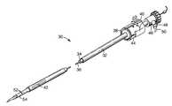
- FIG. 2is a perspective view of a surgical apparatus, with portions cut away, in accordance with the present invention
- FIG. 3is an enlarged, side view of a distal portion of the surgical apparatus of FIG. 2;
- FIGS. 4A and 4Bare schematic views of a portion of the surgical apparatus of FIG. 2;
- FIG. 4Cis an exploded, perspective view of a portion of the surgical apparatus of FIG. 2;
- FIGS. 5-8are side views of a surgical apparatus in accordance with the present invention, depicting various positions of an outer tube relative to an inner tube.
- FIG. 1illustrates in block form a system 10 for RF ablation useful with the present invention.
- the system 10includes a source of radiofrequency alternating electric current 12 , a source of RF ablating fluid 14 , including but not limited to saline and other conductive solutions, and a surgical instrument 16 for delivering RF current and ablation fluid to a tissue site (not shown) for ablation purposes.
- the surgical instrument 16is connected to the current source 12 and the fluid source 14 .
- the current source 12 and the fluid source 14may be combined into a single operational structure controlled by an appropriate microprocessor for a controlled delivery of ablating fluid and a controlled application of RF current, both based upon measured parameters such as but not limited to, flow rate, tissue temperature at the ablation site and at areas surrounding the ablation site, impedance, the rate of change of the impedance, the detection of arcing between the surgical instrument and the tissue, the time period during which the ablation procedure has been operating, and additional factors as desired.
- the surgical instrument 16is shown as being connected to both the current source 12 and the fluid source 14 , the present system is not so limited but could include separate needles or other instruments useful in RF liquid ablation procedures, that is, for example, a single straight or coiled needle having an exposed end and a fluid flow path there through could be used to deliver both fluid and current to the target tissue for ablation purposes. Alternatively, a separate needle could be used to deliver the current and a separate needle or needles could be used to deliver fluid to the target tissue.
- the application of the present systemis not limited to the use of straight needles or helical needles as surgical instruments but could find use with any type of instrument wherein a conductive solution is delivered to a tissue and an RF current is applied to the tissue through the conductive fluid. Such instruments thus would include straight needles, helical needles, forceps, roller balls, instruments for the treatment of vascular disorders, and any other instrument.
- the system 10further includes a second fluid source 18 for delivery of tissue protecting fluid via a delivery instrument 20 , to a tissue whose ablation is not desired.
- the surgical instrument 16may assume a wide variety of forms.
- a surgical apparatus 30 useful in an RF ablation procedureis shown in FIG. 2 .
- the apparatus 30includes an outer thin walled tube 32 , an inner thinner walled tube 34 , and may, if desired, include an inner stylet or probe 36 .
- Tubes 32 and 34 and stylet 36are substantially coaxially mounted relative to each other and are movable in the proximal-distal direction relative to each other.
- the outer tube 32preferably includes a collar 38 with a control knob 40 attached at a proximal end thereof.
- the outer tube 32further preferably includes at least one slot or aperture 42 located at a distal end thereof. If desired, multiple apertures 42 may be disposed in any desired manner about the circumference of the distal end of the outer tube 32 .
- the aperture 42may take on multiple configurations. In the embodiment shown in FIG. 2, the aperture 42 has an elongated oval or elliptical configuration.
- the inner tube 34is configured as a needle electrode.
- the inner tube 34which is slidably received within the outer tube 32 , preferably includes a shutter index element 44 attached adjacent a proximal end thereof.
- the shutter index element 44will be discussed in further detail below.
- Attached to a proximal end of the inner tube 34is a hemostasis valve 46 having a port 48 through which RF ablating fluid, such as but not limited to saline and other conductive solutions, may be supplied from the fluid source 14 (FIG. 1) as indicated by arrow 50 .
- a distal end of the inner tube 34includes a plurality of orifices or apertures 52 of varying sizes and shapes as desired. As shown in FIG.
- each setincludes five apertures increasing in size toward a center of the individual set.
- the bolus of the fluid forming at a particular target sitemay take on a roughly elliptical shape, making allowances for the tissue at the target site and the vasculature that may be implicated by any particular placement.
- the inner tube 34includes at its most distal end an exposed electrode 54 through which RF current can be applied to the tissue.
- the inner tube 34may be metallic or otherwise conductive and insulated along its length except for the exposed electrode 54 .
- the electrode 54is preferably electrically connected to the current source 12 (FIG. 1 ).
- FIG. 3illustrates a plan view of the distal end of the inner tube or needle electrode 34 . It will be understood that the needle electrode 34 will be insulated except at the distal end to prevent electrical current from flowing into the tissue (not shown) at any location except from the distal end thereof.
- the probe 36may take the form of an inner stylet, preferably having a thermocouple (not shown) disposed at the distal end thereof. Because the probe 36 is movable relative to the electrode 54 , the thermocouple may be placed at a desired location away from the electrode to monitor tissue temperature.
- FIGS. 4A-4Cillustrate in greater detail the connections between the control knob 40 and the outer tube 32 on the one hand, and the shutter index element 44 and the inner tube 34 on the other.
- the control knob 40is preferably connected to the collar 38 of the outer tube 32 by a support 56 .
- the outer tube 32 and the control knob 40are rotatable and axially movable relative to the inner tube 34 and the shutter index element 44 .
- the control knob 40can be selectively moved into and out of engagement with a portion of the shutter index element 44 .
- the control knob 40may be rotated from a first engagement position (FIG. 4 A), and then moved axially to a second engagement position (FIG. 4 B).
- the shutter index element 44is preferably configured to form axial slots 58 a - 58 d sized to receive the support 56 .
- Each of the axial slots 58 a - 58 dis connected to at least one circumferential slot, similarly sized to receive and selectively maintain the support 56 .
- the axial slot 58 ais shown as being connected to three circumferential slots 60
- the axial slot 58 bis connected to one circumferential slot 62 . Any other number of circumferential slots is equally acceptable and dictates a desired position(s) of the outer tube 32 relative to the inner tube 34 , as described in greater detail below.
- FIGS. 5-8Translation of the control knob 40 /outer tube 32 relative to the shutter index element 44 /inner tube 34 and the effect on fluid flow is shown in greater detail in FIGS. 5-8.
- the control knob 40(FIG. 4A) has not been shown for purposes of clarity. Instead, only the support 56 , which extends from the control knob 40 to the collar 38 (FIG. 4 A), has been depicted.
- the shutter index element 44is shown as including the axial slot 58 a connected to four circumferential slots 64 a - 64 d.
- the support 56can be maneuvered along the axial slot 58 a into selective engagement with each of the circumferential slots 64 a - 64 d, thereby locating the support 56 within any one of the circumferential slots 64 a - 64 d and resulting in a defined relationship of the outer tube 32 relative to the inner tube 34 .
- the shutter index element 44may further include indicia 66 a - 66 d associated with the circumferential slots 64 a - 64 d, respectively.
- the indicia 66 a - 66 dmay assume a wide variety of forms for providing a user with an indication of outer tube 32 /inner tube 34 positioning.
- the indicia 66 amay be a filled circle (“ ⁇ ”) representing that all of the orifices 52 of the inner tube 34 are open; the indicia 66 b may be a half filled circle (“X”) representing the orifices 52 being partially open; the indicia 66 c may be an open circle (“o”) representing all of the orifices 52 being closed; and the indicia 66 d may be a dash (“—”) representing the slot 42 of the outer tube 32 being open or aligned with the orifices 52 .
- FIG. 5illustrates the situation where the control knob 40 (FIG. 4A) has been moved to a position where the orifices 52 are fully opened and allow RF fluid to flow freely therefrom. That is to say, the support 56 is positioned within the circumferential slot 64 a. At this location, a distal end of the outer tube 32 is proximal the orifices 52 and the electrode 54 . Fluid from the fluid source 14 (FIG. 1) is thereby allowed to flow from the orifices 52 .
- FIG. 6illustrates the partial blocking of the orifices 52 .
- the control knob 40(FIG. 4A) has been rotated relative to the shutter index element 42 and moved distally along the axial slot 58 a so as to move the outer tube 32 distally relative to the inner tube 34 .
- the control knob 40has then been rotated radially to lodge the support 56 in the circumferential slot 64 b. Movement of the outer tube 32 in this manner (e.g., distally) causes the outer tube 32 to partially block at least some of the orifices 52 and thus restrict or stop RF fluid flow therefrom, as identified by the indicia 66 b.
- FIG. 7illustrates the complete blocking of RF fluid flow from all of the apertures 52 . More particularly, the support 56 has been moved into the circumferential slot 66 c, resulting in a distal end of the outer tube 32 being distal the orifices 52 . In FIG. 8, the slot 42 at the distal end of outer tube 32 has been moved such that fluid flows only from the orifices 52 and then through the slot 42 , thus providing in essence a single aperture along a longitudinal length of the outer tube 32 rather than discrete multiple apertures.
- the indicia 66 dprovides visual notice of this relationship to the user.
- the present inventionallows an operator to block the distribution of the RF fluid from the apparatus 30 in a selective manner. This allows the operator to control the volume of the fluid flow and the shape of the bolus or virtual electrode produced in the tissue with some degree of latitude as allowed by the tissue structure in which the apparatus is placed.
Landscapes
- Health & Medical Sciences (AREA)
- Surgery (AREA)
- Engineering & Computer Science (AREA)
- Life Sciences & Earth Sciences (AREA)
- Biomedical Technology (AREA)
- Otolaryngology (AREA)
- Nuclear Medicine, Radiotherapy & Molecular Imaging (AREA)
- Plasma & Fusion (AREA)
- Physics & Mathematics (AREA)
- Heart & Thoracic Surgery (AREA)
- Medical Informatics (AREA)
- Molecular Biology (AREA)
- Animal Behavior & Ethology (AREA)
- General Health & Medical Sciences (AREA)
- Public Health (AREA)
- Veterinary Medicine (AREA)
- Surgical Instruments (AREA)
Abstract
Description
Claims (20)
Priority Applications (1)
| Application Number | Priority Date | Filing Date | Title |
|---|---|---|---|
| US09/903,274US6497705B2 (en) | 1998-07-07 | 2001-07-11 | Method and apparatus for creating a virtual electrode used for the ablation of tissue |
Applications Claiming Priority (3)
| Application Number | Priority Date | Filing Date | Title |
|---|---|---|---|
| US9194898P | 1998-07-07 | 1998-07-07 | |
| US09/347,380US6315777B1 (en) | 1998-07-07 | 1999-07-06 | Method and apparatus for creating a virtual electrode used for the ablation of tissue |
| US09/903,274US6497705B2 (en) | 1998-07-07 | 2001-07-11 | Method and apparatus for creating a virtual electrode used for the ablation of tissue |
Related Parent Applications (1)
| Application Number | Title | Priority Date | Filing Date |
|---|---|---|---|
| US09/347,380ContinuationUS6315777B1 (en) | 1998-07-07 | 1999-07-06 | Method and apparatus for creating a virtual electrode used for the ablation of tissue |
Publications (2)
| Publication Number | Publication Date |
|---|---|
| US20020019628A1 US20020019628A1 (en) | 2002-02-14 |
| US6497705B2true US6497705B2 (en) | 2002-12-24 |
Family
ID=26784501
Family Applications (2)
| Application Number | Title | Priority Date | Filing Date |
|---|---|---|---|
| US09/347,380Expired - LifetimeUS6315777B1 (en) | 1998-07-07 | 1999-07-06 | Method and apparatus for creating a virtual electrode used for the ablation of tissue |
| US09/903,274Expired - LifetimeUS6497705B2 (en) | 1998-07-07 | 2001-07-11 | Method and apparatus for creating a virtual electrode used for the ablation of tissue |
Family Applications Before (1)
| Application Number | Title | Priority Date | Filing Date |
|---|---|---|---|
| US09/347,380Expired - LifetimeUS6315777B1 (en) | 1998-07-07 | 1999-07-06 | Method and apparatus for creating a virtual electrode used for the ablation of tissue |
Country Status (1)
| Country | Link |
|---|---|
| US (2) | US6315777B1 (en) |
Cited By (80)
| Publication number | Priority date | Publication date | Assignee | Title |
|---|---|---|---|---|
| US20040215181A1 (en)* | 2003-04-25 | 2004-10-28 | Medtronic, Inc. | Delivery of fluid during transurethral prostate treatment |
| US20050055019A1 (en)* | 2003-09-05 | 2005-03-10 | Medtronic, Inc. | RF ablation catheter including a virtual electrode assembly |
| US20050228374A1 (en)* | 2002-05-27 | 2005-10-13 | Kai Desinger | Therapy apparatus for thermal sclerosing of body tissue |
| US20050245924A1 (en)* | 2004-04-30 | 2005-11-03 | Medtronic, Inc. | Ion eluting tuna device |
| US20060036235A1 (en)* | 2004-08-10 | 2006-02-16 | Medtronic, Inc. | TUNA device with integrated saline resevoir |
| US20060129144A1 (en)* | 2003-02-19 | 2006-06-15 | Shin Kyong M | Electrode device for high frequency thermotherapy |
| US20070179491A1 (en)* | 2006-01-31 | 2007-08-02 | Medtronic, Inc. | Sensing needle for ablation therapy |
| US7422588B2 (en) | 1995-02-22 | 2008-09-09 | Medtronic, Inc. | Pen-type electrosurgical instrument |
| US20080262491A1 (en)* | 2004-08-10 | 2008-10-23 | Medtronic, Inc. | Tuna Device with Integrated Saline Reservoir |
| US20080269862A1 (en)* | 2007-04-30 | 2008-10-30 | Medtronic, Inc. | Extension and retraction mechanism for a hand-held device |
| US20080275440A1 (en)* | 2007-05-03 | 2008-11-06 | Medtronic, Inc. | Post-ablation verification of lesion size |
| US20080312497A1 (en)* | 2007-06-14 | 2008-12-18 | Medtronic, Inc. | Distal viewing window of a medical catheter |
| US7470272B2 (en) | 1997-07-18 | 2008-12-30 | Medtronic, Inc. | Device and method for ablating tissue |
| US7537595B2 (en) | 2001-12-12 | 2009-05-26 | Tissuelink Medical, Inc. | Fluid-assisted medical devices, systems and methods |
| US7604635B2 (en) | 2000-03-06 | 2009-10-20 | Salient Surgical Technologies, Inc. | Fluid-assisted medical devices, systems and methods |
| US7645277B2 (en) | 2000-09-22 | 2010-01-12 | Salient Surgical Technologies, Inc. | Fluid-assisted medical device |
| US20100042095A1 (en)* | 2008-08-13 | 2010-02-18 | Robert Bigley | Systems and methods for screen electrode securement |
| US7727232B1 (en) | 2004-02-04 | 2010-06-01 | Salient Surgical Technologies, Inc. | Fluid-assisted medical devices and methods |
| US7811282B2 (en) | 2000-03-06 | 2010-10-12 | Salient Surgical Technologies, Inc. | Fluid-assisted electrosurgical devices, electrosurgical unit with pump and methods of use thereof |
| US7815634B2 (en) | 2000-03-06 | 2010-10-19 | Salient Surgical Technologies, Inc. | Fluid delivery system and controller for electrosurgical devices |
| US7860555B2 (en) | 2005-02-02 | 2010-12-28 | Voyage Medical, Inc. | Tissue visualization and manipulation system |
| US7860556B2 (en) | 2005-02-02 | 2010-12-28 | Voyage Medical, Inc. | Tissue imaging and extraction systems |
| US20110077646A1 (en)* | 2009-09-25 | 2011-03-31 | Dahla Robert H | System, method and apparatus for electrosurgical instrument with movable fluid delivery sheath |
| US20110077643A1 (en)* | 2009-09-25 | 2011-03-31 | Dahla Robert H | System, method and apparatus for electrosurgical instrument with movable suction sheath |
| US7918787B2 (en) | 2005-02-02 | 2011-04-05 | Voyage Medical, Inc. | Tissue visualization and manipulation systems |
| US7930016B1 (en) | 2005-02-02 | 2011-04-19 | Voyage Medical, Inc. | Tissue closure system |
| US7951148B2 (en) | 2001-03-08 | 2011-05-31 | Salient Surgical Technologies, Inc. | Electrosurgical device having a tissue reduction sensor |
| US7998140B2 (en) | 2002-02-12 | 2011-08-16 | Salient Surgical Technologies, Inc. | Fluid-assisted medical devices, systems and methods |
| US8050746B2 (en) | 2005-02-02 | 2011-11-01 | Voyage Medical, Inc. | Tissue visualization device and method variations |
| US8048069B2 (en) | 2006-09-29 | 2011-11-01 | Medtronic, Inc. | User interface for ablation therapy |
| US8078266B2 (en) | 2005-10-25 | 2011-12-13 | Voyage Medical, Inc. | Flow reduction hood systems |
| US8131350B2 (en) | 2006-12-21 | 2012-03-06 | Voyage Medical, Inc. | Stabilization of visualization catheters |
| US8137333B2 (en) | 2005-10-25 | 2012-03-20 | Voyage Medical, Inc. | Delivery of biological compounds to ischemic and/or infarcted tissue |
| US8221310B2 (en) | 2005-10-25 | 2012-07-17 | Voyage Medical, Inc. | Tissue visualization device and method variations |
| US8235985B2 (en) | 2007-08-31 | 2012-08-07 | Voyage Medical, Inc. | Visualization and ablation system variations |
| US20120215217A1 (en)* | 2011-02-17 | 2012-08-23 | Horner Shawn K | Surgical instrument with protective sheath |
| US8333012B2 (en) | 2008-10-10 | 2012-12-18 | Voyage Medical, Inc. | Method of forming electrode placement and connection systems |
| US8355799B2 (en) | 2008-12-12 | 2013-01-15 | Arthrocare Corporation | Systems and methods for limiting joint temperature |
| US8475455B2 (en) | 2002-10-29 | 2013-07-02 | Medtronic Advanced Energy Llc | Fluid-assisted electrosurgical scissors and methods |
| US8551088B2 (en) | 2008-03-31 | 2013-10-08 | Applied Medical Resources Corporation | Electrosurgical system |
| US8657805B2 (en) | 2007-05-08 | 2014-02-25 | Intuitive Surgical Operations, Inc. | Complex shape steerable tissue visualization and manipulation catheter |
| US8663216B2 (en) | 1998-08-11 | 2014-03-04 | Paul O. Davison | Instrument for electrosurgical tissue treatment |
| US8694071B2 (en) | 2010-02-12 | 2014-04-08 | Intuitive Surgical Operations, Inc. | Image stabilization techniques and methods |
| US8696659B2 (en) | 2010-04-30 | 2014-04-15 | Arthrocare Corporation | Electrosurgical system and method having enhanced temperature measurement |
| US8709008B2 (en) | 2007-05-11 | 2014-04-29 | Intuitive Surgical Operations, Inc. | Visual electrode ablation systems |
| US8758229B2 (en) | 2006-12-21 | 2014-06-24 | Intuitive Surgical Operations, Inc. | Axial visualization systems |
| WO2014150887A1 (en)* | 2013-03-15 | 2014-09-25 | Cibiem, Inc. | Endovascular catheters for carotid body ablation utilizing an ionic liquid stream |
| US8858609B2 (en) | 2008-02-07 | 2014-10-14 | Intuitive Surgical Operations, Inc. | Stent delivery under direct visualization |
| US8934962B2 (en) | 2005-02-02 | 2015-01-13 | Intuitive Surgical Operations, Inc. | Electrophysiology mapping and visualization system |
| US8945114B2 (en) | 2007-04-26 | 2015-02-03 | Medtronic, Inc. | Fluid sensor for ablation therapy |
| US9055906B2 (en) | 2006-06-14 | 2015-06-16 | Intuitive Surgical Operations, Inc. | In-vivo visualization systems |
| US9089700B2 (en) | 2008-08-11 | 2015-07-28 | Cibiem, Inc. | Systems and methods for treating dyspnea, including via electrical afferent signal blocking |
| US9101735B2 (en) | 2008-07-07 | 2015-08-11 | Intuitive Surgical Operations, Inc. | Catheter control systems |
| US9155452B2 (en) | 2007-04-27 | 2015-10-13 | Intuitive Surgical Operations, Inc. | Complex shape steerable tissue visualization and manipulation catheter |
| USD748259S1 (en) | 2014-12-29 | 2016-01-26 | Applied Medical Resources Corporation | Electrosurgical instrument |
| US9283033B2 (en) | 2012-06-30 | 2016-03-15 | Cibiem, Inc. | Carotid body ablation via directed energy |
| US9320563B2 (en) | 2010-10-01 | 2016-04-26 | Applied Medical Resources Corporation | Electrosurgical instruments and connections thereto |
| US9393070B2 (en) | 2012-04-24 | 2016-07-19 | Cibiem, Inc. | Endovascular catheters and methods for carotid body ablation |
| US9398930B2 (en) | 2012-06-01 | 2016-07-26 | Cibiem, Inc. | Percutaneous methods and devices for carotid body ablation |
| US9402677B2 (en) | 2012-06-01 | 2016-08-02 | Cibiem, Inc. | Methods and devices for cryogenic carotid body ablation |
| US9468364B2 (en) | 2008-11-14 | 2016-10-18 | Intuitive Surgical Operations, Inc. | Intravascular catheter with hood and image processing systems |
| US9510732B2 (en) | 2005-10-25 | 2016-12-06 | Intuitive Surgical Operations, Inc. | Methods and apparatus for efficient purging |
| US9597142B2 (en) | 2014-07-24 | 2017-03-21 | Arthrocare Corporation | Method and system related to electrosurgical procedures |
| US9649148B2 (en) | 2014-07-24 | 2017-05-16 | Arthrocare Corporation | Electrosurgical system and method having enhanced arc prevention |
| US9814522B2 (en) | 2010-04-06 | 2017-11-14 | Intuitive Surgical Operations, Inc. | Apparatus and methods for ablation efficacy |
| US9955946B2 (en) | 2014-03-12 | 2018-05-01 | Cibiem, Inc. | Carotid body ablation with a transvenous ultrasound imaging and ablation catheter |
| US10004388B2 (en) | 2006-09-01 | 2018-06-26 | Intuitive Surgical Operations, Inc. | Coronary sinus cannulation |
| US10064540B2 (en) | 2005-02-02 | 2018-09-04 | Intuitive Surgical Operations, Inc. | Visualization apparatus for transseptal access |
| US10070772B2 (en) | 2006-09-01 | 2018-09-11 | Intuitive Surgical Operations, Inc. | Precision control systems for tissue visualization and manipulation assemblies |
| US10111705B2 (en) | 2008-10-10 | 2018-10-30 | Intuitive Surgical Operations, Inc. | Integral electrode placement and connection systems |
| US10149713B2 (en) | 2014-05-16 | 2018-12-11 | Applied Medical Resources Corporation | Electrosurgical system |
| US10335131B2 (en) | 2006-10-23 | 2019-07-02 | Intuitive Surgical Operations, Inc. | Methods for preventing tissue migration |
| US10420603B2 (en) | 2014-12-23 | 2019-09-24 | Applied Medical Resources Corporation | Bipolar electrosurgical sealer and divider |
| US10441136B2 (en) | 2006-12-18 | 2019-10-15 | Intuitive Surgical Operations, Inc. | Systems and methods for unobstructed visualization and ablation |
| US10792092B2 (en) | 2014-05-30 | 2020-10-06 | Applied Medical Resources Corporation | Electrosurgical seal and dissection systems |
| US11406250B2 (en) | 2005-02-02 | 2022-08-09 | Intuitive Surgical Operations, Inc. | Methods and apparatus for treatment of atrial fibrillation |
| US11478152B2 (en) | 2005-02-02 | 2022-10-25 | Intuitive Surgical Operations, Inc. | Electrophysiology mapping and visualization system |
| US11696796B2 (en) | 2018-11-16 | 2023-07-11 | Applied Medical Resources Corporation | Electrosurgical system |
| US11864812B2 (en) | 2018-09-05 | 2024-01-09 | Applied Medical Resources Corporation | Electrosurgical generator control system |
| US12396786B2 (en) | 2019-03-22 | 2025-08-26 | Stryker Corporation | Systems for ablating tissue |
Families Citing this family (94)
| Publication number | Priority date | Publication date | Assignee | Title |
|---|---|---|---|---|
| US7077842B1 (en)* | 2001-08-03 | 2006-07-18 | Cosman Jr Eric R | Over-the-wire high frequency electrode |
| US7285116B2 (en)* | 2004-05-15 | 2007-10-23 | Irvine Biomedical Inc. | Non-contact tissue ablation device and methods thereof |
| US8974446B2 (en)* | 2001-10-11 | 2015-03-10 | St. Jude Medical, Inc. | Ultrasound ablation apparatus with discrete staggered ablation zones |
| US7306596B2 (en)* | 2004-05-26 | 2007-12-11 | Baylis Medical Company Inc. | Multifunctional electrosurgical apparatus |
| US6887237B2 (en) | 2002-07-22 | 2005-05-03 | Medtronic, Inc. | Method for treating tissue with a wet electrode and apparatus for using same |
| US6926713B2 (en)* | 2002-12-11 | 2005-08-09 | Boston Scientific Scimed, Inc. | Angle indexer for medical devices |
| US20040143262A1 (en)* | 2003-01-21 | 2004-07-22 | Baylis Medical Company Inc. | Surgical perforation device and method with pressure monitoring and staining abilities |
| FR2854052A1 (en)* | 2003-04-25 | 2004-10-29 | Medtronic Inc | Transurethral ablation system, includes catheter with needle emerging to penetrate prostate, fluid distribution system and electrical ablation energy generator |
| US20050096629A1 (en)* | 2003-10-31 | 2005-05-05 | Medtronic, Inc. | Techniques for transurethral delivery of a denervating agent to the prostate gland |
| US20050096549A1 (en)* | 2003-10-31 | 2005-05-05 | Medtronic, Inc. | Techniques for transperineal delivery of a denervating agent to the prostate gland |
| US20050096550A1 (en)* | 2003-10-31 | 2005-05-05 | Medtronic, Inc. | Techniques for transrectal delivery of a denervating agent to the prostate gland |
| US8187268B2 (en)* | 2004-05-26 | 2012-05-29 | Kimberly-Clark, Inc. | Electrosurgical apparatus having a temperature sensor |
| US7261710B2 (en)* | 2004-10-13 | 2007-08-28 | Medtronic, Inc. | Transurethral needle ablation system |
| USD582038S1 (en) | 2004-10-13 | 2008-12-02 | Medtronic, Inc. | Transurethral needle ablation device |
| US7261709B2 (en)* | 2004-10-13 | 2007-08-28 | Medtronic, Inc. | Transurethral needle ablation system with automatic needle retraction |
| US7335197B2 (en)* | 2004-10-13 | 2008-02-26 | Medtronic, Inc. | Transurethral needle ablation system with flexible catheter tip |
| US20060079881A1 (en)* | 2004-10-13 | 2006-04-13 | Christopherson Mark A | Single-use transurethral needle ablation |
| US10548659B2 (en)* | 2006-01-17 | 2020-02-04 | Ulthera, Inc. | High pressure pre-burst for improved fluid delivery |
| US9486274B2 (en) | 2005-09-07 | 2016-11-08 | Ulthera, Inc. | Dissection handpiece and method for reducing the appearance of cellulite |
| US9011473B2 (en) | 2005-09-07 | 2015-04-21 | Ulthera, Inc. | Dissection handpiece and method for reducing the appearance of cellulite |
| US9358033B2 (en) | 2005-09-07 | 2016-06-07 | Ulthera, Inc. | Fluid-jet dissection system and method for reducing the appearance of cellulite |
| US8518069B2 (en) | 2005-09-07 | 2013-08-27 | Cabochon Aesthetics, Inc. | Dissection handpiece and method for reducing the appearance of cellulite |
| US8430863B2 (en)* | 2005-12-02 | 2013-04-30 | Abbott Cardiovascular Systems Inc. | Visualization of a catheter viewed under ultrasound imaging |
| US9248317B2 (en) | 2005-12-02 | 2016-02-02 | Ulthera, Inc. | Devices and methods for selectively lysing cells |
| US7885793B2 (en) | 2007-05-22 | 2011-02-08 | International Business Machines Corporation | Method and system for developing a conceptual model to facilitate generating a business-aligned information technology solution |
| WO2007089675A2 (en)* | 2006-01-27 | 2007-08-09 | Medtronic, Inc. | Ablation device and system for guiding said ablation device into a patient's body |
| US7976542B1 (en)* | 2006-03-02 | 2011-07-12 | Cosman Eric R | Adjustable high frequency electrode |
| US12161390B2 (en) | 2006-09-29 | 2024-12-10 | Boston Scientific Medical Device Limited | Connector system for electrosurgical device |
| US11666377B2 (en) | 2006-09-29 | 2023-06-06 | Boston Scientific Medical Device Limited | Electrosurgical device |
| CN100594008C (en)* | 2007-01-16 | 2010-03-17 | 盛林 | microwave ablation waterjet |
| US8439940B2 (en) | 2010-12-22 | 2013-05-14 | Cabochon Aesthetics, Inc. | Dissection handpiece with aspiration means for reducing the appearance of cellulite |
| CN102271595A (en) | 2008-11-06 | 2011-12-07 | 恩克斯特拉公司 | Systems and methods for treatment of bph |
| CN105434039B (en) | 2008-11-06 | 2019-01-15 | 恩克斯特拉公司 | System and method for treating prostata tissue |
| JP2010213946A (en)* | 2009-03-18 | 2010-09-30 | Fujifilm Corp | High frequency treatment instrument |
| US9833277B2 (en) | 2009-04-27 | 2017-12-05 | Nxthera, Inc. | Systems and methods for prostate treatment |
| US9358064B2 (en) | 2009-08-07 | 2016-06-07 | Ulthera, Inc. | Handpiece and methods for performing subcutaneous surgery |
| US11096708B2 (en) | 2009-08-07 | 2021-08-24 | Ulthera, Inc. | Devices and methods for performing subcutaneous surgery |
| EP2549963B1 (en) | 2010-03-25 | 2023-08-23 | Boston Scientific Scimed, Inc. | Systems for prostate treatment |
| US9486275B2 (en) | 2010-12-30 | 2016-11-08 | Avent, Inc. | Electrosurgical apparatus having a sensor |
| ES2864589T3 (en) | 2011-04-12 | 2021-10-14 | Thermedical Inc | Devices for conformal therapy in fluid-enhanced ablation |
| CN103917200B (en) | 2011-09-13 | 2016-03-30 | 恩克斯特拉公司 | Systems and methods for prostate treatment |
| EP2833815B1 (en) | 2012-04-03 | 2020-11-11 | Boston Scientific Scimed, Inc. | Induction coil vapor generator |
| EP4599879A2 (en) | 2012-05-31 | 2025-08-13 | Boston Scientific Medical Device Limited | Radiofrequency perforation apparatus |
| US10022176B2 (en) | 2012-08-15 | 2018-07-17 | Thermedical, Inc. | Low profile fluid enhanced ablation therapy devices and methods |
| US9439665B2 (en) | 2012-12-20 | 2016-09-13 | Covidien Lp | Pediatric combination surgical device |
| EP2968846B1 (en) | 2013-03-12 | 2022-05-04 | Baylis Medical Company Inc. | Medical device having a support structure |
| US11937873B2 (en) | 2013-03-12 | 2024-03-26 | Boston Scientific Medical Device Limited | Electrosurgical device having a lumen |
| BR112015022358A2 (en) | 2013-03-14 | 2017-07-18 | Nxthera Inc | method for treating abnormal prostate tissue, and, method for treating prostate cancer, and, prostate cancer therapy system |
| US9033972B2 (en) | 2013-03-15 | 2015-05-19 | Thermedical, Inc. | Methods and devices for fluid enhanced microwave ablation therapy |
| US9610396B2 (en) | 2013-03-15 | 2017-04-04 | Thermedical, Inc. | Systems and methods for visualizing fluid enhanced ablation therapy |
| CA3220441A1 (en) | 2013-03-15 | 2015-09-17 | Boston Scientific Medical Device Limited | Electrosurgical device having a distal aperture |
| CN105682726B (en) | 2013-08-07 | 2020-01-03 | 贝利斯医疗公司 | Method and apparatus for puncturing tissue |
| US9968395B2 (en) | 2013-12-10 | 2018-05-15 | Nxthera, Inc. | Systems and methods for treating the prostate |
| US10194970B2 (en) | 2013-12-10 | 2019-02-05 | Nxthera, Inc. | Vapor ablation systems and methods |
| US10661057B2 (en) | 2013-12-20 | 2020-05-26 | Baylis Medical Company Inc. | Steerable medical device handle |
| WO2015153815A1 (en) | 2014-04-01 | 2015-10-08 | Gregory Brucker | Temperature-responsive irrigated ablation electrode with reduced coolant flow and related methods for making and using |
| US10342593B2 (en) | 2015-01-29 | 2019-07-09 | Nxthera, Inc. | Vapor ablation systems and methods |
| CA2982372A1 (en) | 2015-05-13 | 2016-11-17 | Nxthera, Inc. | Systems and methods for treating the bladder with condensable vapor |
| AU2016319002B2 (en) | 2015-09-09 | 2021-05-13 | Boston Scientific Medical Device Limited | Epicardial access system & methods |
| WO2017118948A1 (en) | 2016-01-07 | 2017-07-13 | Baylis Medical Company Inc. | Hybrid transseptal dilator and methods of using the same |
| US9743984B1 (en) | 2016-08-11 | 2017-08-29 | Thermedical, Inc. | Devices and methods for delivering fluid to tissue during ablation therapy |
| CN110114027B (en) | 2016-11-01 | 2022-09-06 | 贝利斯医疗公司 | Method and apparatus for puncturing tissue |
| JP7129980B2 (en) | 2016-12-21 | 2022-09-02 | ボストン サイエンティフィック サイムド,インコーポレイテッド | Steam cautery system and method |
| WO2018129466A1 (en) | 2017-01-06 | 2018-07-12 | Nxthera, Inc. | Transperineal vapor ablation systems and methods |
| BR112020011128A2 (en) | 2017-08-10 | 2021-05-04 | Baylis Medical Company Inc. | heat exchange device and temperature sensor and method of use |
| CN119950019A (en)* | 2017-11-28 | 2025-05-09 | 杭州诺诚医疗器械有限公司 | Ablation needle assembly and ablation system |
| EP3579909B1 (en) | 2017-12-05 | 2020-09-09 | Pedersen, Wesley Robert | Transseptal guide wire puncture system |
| US11083871B2 (en) | 2018-05-03 | 2021-08-10 | Thermedical, Inc. | Selectively deployable catheter ablation devices |
| CN112272574A (en) | 2018-05-08 | 2021-01-26 | 贝利斯医疗公司 | Coupling mechanism for device |
| US11918277B2 (en) | 2018-07-16 | 2024-03-05 | Thermedical, Inc. | Inferred maximum temperature monitoring for irrigated ablation therapy |
| US11432733B2 (en) | 2019-03-13 | 2022-09-06 | Blossom Innovations | Tissue detection devices, systems and methods |
| US12262976B2 (en) | 2019-03-13 | 2025-04-01 | Blossom Innovations Llc | Devices, systems and methods for tissue analysis, location determination and therapy thereof using optical radiation |
| KR20220021468A (en) | 2019-04-29 | 2022-02-22 | 베이리스 메디컬 컴퍼니 아이엔씨. | Transseptal system, device and method |
| US11759190B2 (en) | 2019-10-18 | 2023-09-19 | Boston Scientific Medical Device Limited | Lock for medical devices, and related systems and methods |
| US11801087B2 (en) | 2019-11-13 | 2023-10-31 | Boston Scientific Medical Device Limited | Apparatus and methods for puncturing tissue |
| US11191446B2 (en)* | 2019-11-27 | 2021-12-07 | Blossom Innovations, LLC | Devices, systems and methods for tissue analysis, locaton determination and tissue ablation |
| US11724070B2 (en) | 2019-12-19 | 2023-08-15 | Boston Scientific Medical Device Limited | Methods for determining a position of a first medical device with respect to a second medical device, and related systems and medical devices |
| US11931098B2 (en) | 2020-02-19 | 2024-03-19 | Boston Scientific Medical Device Limited | System and method for carrying out a medical procedure |
| US11986209B2 (en) | 2020-02-25 | 2024-05-21 | Boston Scientific Medical Device Limited | Methods and devices for creation of communication between aorta and left atrium |
| US12082792B2 (en) | 2020-02-25 | 2024-09-10 | Boston Scientific Medical Device Limited | Systems and methods for creating a puncture between aorta and the left atrium |
| US11819243B2 (en) | 2020-03-19 | 2023-11-21 | Boston Scientific Medical Device Limited | Medical sheath and related systems and methods |
| US11826075B2 (en) | 2020-04-07 | 2023-11-28 | Boston Scientific Medical Device Limited | Elongated medical assembly |
| US12011279B2 (en) | 2020-04-07 | 2024-06-18 | Boston Scientific Medical Device Limited | Electro-anatomic mapping system |
| US12420067B2 (en) | 2020-05-12 | 2025-09-23 | Boston Scientific Medical Device Limited | Guidewire assembly |
| CN116437857A (en) | 2020-06-17 | 2023-07-14 | 波士顿科学医疗设备有限公司 | Electroanatomical mapping system |
| US11938285B2 (en) | 2020-06-17 | 2024-03-26 | Boston Scientific Medical Device Limited | Stop-movement device for elongated medical assembly |
| US11937796B2 (en) | 2020-06-18 | 2024-03-26 | Boston Scientific Medical Device Limited | Tissue-spreader assembly |
| US12343042B2 (en) | 2020-07-16 | 2025-07-01 | Boston Scientific Medical Device Limited | Pericardial puncture device and method |
| US12042178B2 (en) | 2020-07-21 | 2024-07-23 | Boston Scientific Medical Device Limited | System of medical devices and method for pericardial puncture |
| US12005202B2 (en) | 2020-08-07 | 2024-06-11 | Boston Scientific Medical Device Limited | Catheter having tissue-engaging device |
| US12396785B2 (en) | 2020-08-12 | 2025-08-26 | Boston Scientific Medical Device Limited | System of medical devices and method for pericardial puncture |
| CA3128527A1 (en) | 2020-09-10 | 2022-03-10 | Baylis Medical Company Inc. | Elongated medical catheter including marker band |
| US11980412B2 (en) | 2020-09-15 | 2024-05-14 | Boston Scientific Medical Device Limited | Elongated medical sheath |
| KR102595891B1 (en)* | 2021-05-07 | 2023-11-01 | 주식회사 스타메드 | Electrode apparatus including high-frequency electrode and multi-function electrode |
Citations (3)
| Publication number | Priority date | Publication date | Assignee | Title |
|---|---|---|---|---|
| US5785706A (en)* | 1996-11-18 | 1998-07-28 | Daig Corporation | Nonsurgical mapping and treatment of cardiac arrhythmia using a catheter contained within a guiding introducer containing openings |
| US5897553A (en)* | 1995-11-02 | 1999-04-27 | Medtronic, Inc. | Ball point fluid-assisted electrocautery device |
| US6328736B1 (en)* | 1995-02-22 | 2001-12-11 | Medtronic, Inc. | Fluid-assisted electrocautery device |
Family Cites Families (23)
| Publication number | Priority date | Publication date | Assignee | Title |
|---|---|---|---|---|
| US5080660A (en)* | 1990-05-11 | 1992-01-14 | Applied Urology, Inc. | Electrosurgical electrode |
| US5542928A (en) | 1991-05-17 | 1996-08-06 | Innerdyne, Inc. | Method and device for thermal ablation having improved heat transfer |
| WO1992020290A1 (en) | 1991-05-17 | 1992-11-26 | Innerdyne Medical, Inc. | Method and device for thermal ablation |
| US5697281A (en) | 1991-10-09 | 1997-12-16 | Arthrocare Corporation | System and method for electrosurgical cutting and ablation |
| US5697909A (en) | 1992-01-07 | 1997-12-16 | Arthrocare Corporation | Methods and apparatus for surgical cutting |
| US5891095A (en) | 1993-05-10 | 1999-04-06 | Arthrocare Corporation | Electrosurgical treatment of tissue in electrically conductive fluid |
| US5676693A (en) | 1992-11-13 | 1997-10-14 | Scimed Life Systems, Inc. | Electrophysiology device |
| DE4338758C2 (en) | 1992-11-13 | 2001-08-09 | Scimed Life Systems Inc | Catheter assembly |
| US6068653A (en)* | 1992-11-13 | 2000-05-30 | Scimed Life Systems, Inc. | Electrophysiology catheter device |
| US5348554A (en) | 1992-12-01 | 1994-09-20 | Cardiac Pathways Corporation | Catheter for RF ablation with cooled electrode |
| US5403311A (en) | 1993-03-29 | 1995-04-04 | Boston Scientific Corporation | Electro-coagulation and ablation and other electrotherapeutic treatments of body tissue |
| US5807395A (en) | 1993-08-27 | 1998-09-15 | Medtronic, Inc. | Method and apparatus for RF ablation and hyperthermia |
| US5431649A (en) | 1993-08-27 | 1995-07-11 | Medtronic, Inc. | Method and apparatus for R-F ablation |
| US5472441A (en)* | 1993-11-08 | 1995-12-05 | Zomed International | Device for treating cancer and non-malignant tumors and methods |
| US5876398A (en) | 1994-09-08 | 1999-03-02 | Medtronic, Inc. | Method and apparatus for R-F ablation |
| US5609151A (en) | 1994-09-08 | 1997-03-11 | Medtronic, Inc. | Method for R-F ablation |
| US5653692A (en) | 1995-09-07 | 1997-08-05 | Innerdyne Medical, Inc. | Method and system for direct heating of fluid solution in a hollow body organ |
| US5904711A (en)* | 1996-02-08 | 1999-05-18 | Heartport, Inc. | Expandable thoracoscopic defibrillation catheter system and method |
| US5895417A (en) | 1996-03-06 | 1999-04-20 | Cardiac Pathways Corporation | Deflectable loop design for a linear lesion ablation apparatus |
| US5800482A (en) | 1996-03-06 | 1998-09-01 | Cardiac Pathways Corporation | Apparatus and method for linear lesion ablation |
| US5913854A (en) | 1997-02-04 | 1999-06-22 | Medtronic, Inc. | Fluid cooled ablation catheter and method for making |
| US5993412A (en)* | 1997-05-19 | 1999-11-30 | Bioject, Inc. | Injection apparatus |
| US6010500A (en)* | 1997-07-21 | 2000-01-04 | Cardiac Pathways Corporation | Telescoping apparatus and method for linear lesion ablation |
- 1999
- 1999-07-06USUS09/347,380patent/US6315777B1/ennot_activeExpired - Lifetime
- 2001
- 2001-07-11USUS09/903,274patent/US6497705B2/ennot_activeExpired - Lifetime
Patent Citations (3)
| Publication number | Priority date | Publication date | Assignee | Title |
|---|---|---|---|---|
| US6328736B1 (en)* | 1995-02-22 | 2001-12-11 | Medtronic, Inc. | Fluid-assisted electrocautery device |
| US5897553A (en)* | 1995-11-02 | 1999-04-27 | Medtronic, Inc. | Ball point fluid-assisted electrocautery device |
| US5785706A (en)* | 1996-11-18 | 1998-07-28 | Daig Corporation | Nonsurgical mapping and treatment of cardiac arrhythmia using a catheter contained within a guiding introducer containing openings |
Cited By (160)
| Publication number | Priority date | Publication date | Assignee | Title |
|---|---|---|---|---|
| US7422588B2 (en) | 1995-02-22 | 2008-09-09 | Medtronic, Inc. | Pen-type electrosurgical instrument |
| US7794460B2 (en) | 1995-02-22 | 2010-09-14 | Medtronic, Inc. | Method of ablating tissue |
| US7470272B2 (en) | 1997-07-18 | 2008-12-30 | Medtronic, Inc. | Device and method for ablating tissue |
| US7678111B2 (en) | 1997-07-18 | 2010-03-16 | Medtronic, Inc. | Device and method for ablating tissue |
| US8663216B2 (en) | 1998-08-11 | 2014-03-04 | Paul O. Davison | Instrument for electrosurgical tissue treatment |
| US7811282B2 (en) | 2000-03-06 | 2010-10-12 | Salient Surgical Technologies, Inc. | Fluid-assisted electrosurgical devices, electrosurgical unit with pump and methods of use thereof |
| US7815634B2 (en) | 2000-03-06 | 2010-10-19 | Salient Surgical Technologies, Inc. | Fluid delivery system and controller for electrosurgical devices |
| US8038670B2 (en) | 2000-03-06 | 2011-10-18 | Salient Surgical Technologies, Inc. | Fluid-assisted medical devices, systems and methods |
| US8048070B2 (en) | 2000-03-06 | 2011-11-01 | Salient Surgical Technologies, Inc. | Fluid-assisted medical devices, systems and methods |
| US7604635B2 (en) | 2000-03-06 | 2009-10-20 | Salient Surgical Technologies, Inc. | Fluid-assisted medical devices, systems and methods |
| US8361068B2 (en) | 2000-03-06 | 2013-01-29 | Medtronic Advanced Energy Llc | Fluid-assisted electrosurgical devices, electrosurgical unit with pump and methods of use thereof |
| US7651494B2 (en) | 2000-09-22 | 2010-01-26 | Salient Surgical Technologies, Inc. | Fluid-assisted medical device |
| US7645277B2 (en) | 2000-09-22 | 2010-01-12 | Salient Surgical Technologies, Inc. | Fluid-assisted medical device |
| US7951148B2 (en) | 2001-03-08 | 2011-05-31 | Salient Surgical Technologies, Inc. | Electrosurgical device having a tissue reduction sensor |
| US7537595B2 (en) | 2001-12-12 | 2009-05-26 | Tissuelink Medical, Inc. | Fluid-assisted medical devices, systems and methods |
| US7998140B2 (en) | 2002-02-12 | 2011-08-16 | Salient Surgical Technologies, Inc. | Fluid-assisted medical devices, systems and methods |
| US20050228374A1 (en)* | 2002-05-27 | 2005-10-13 | Kai Desinger | Therapy apparatus for thermal sclerosing of body tissue |
| US20090299366A1 (en)* | 2002-05-27 | 2009-12-03 | Celon Ag Medical Instruments | Therapy device for thermal sclerosing of body tissue |
| US8475455B2 (en) | 2002-10-29 | 2013-07-02 | Medtronic Advanced Energy Llc | Fluid-assisted electrosurgical scissors and methods |
| US20060129144A1 (en)* | 2003-02-19 | 2006-06-15 | Shin Kyong M | Electrode device for high frequency thermotherapy |
| US7354437B2 (en)* | 2003-02-19 | 2008-04-08 | Taewoong Medical Co., Ltd. | Electrode device for high frequency thermotherapy |
| US20040215181A1 (en)* | 2003-04-25 | 2004-10-28 | Medtronic, Inc. | Delivery of fluid during transurethral prostate treatment |
| US20050055019A1 (en)* | 2003-09-05 | 2005-03-10 | Medtronic, Inc. | RF ablation catheter including a virtual electrode assembly |
| US7104989B2 (en) | 2003-09-05 | 2006-09-12 | Medtronic, Inc. | RF ablation catheter including a virtual electrode assembly |
| US7727232B1 (en) | 2004-02-04 | 2010-06-01 | Salient Surgical Technologies, Inc. | Fluid-assisted medical devices and methods |
| US8075557B2 (en) | 2004-02-04 | 2011-12-13 | Salient Surgical Technologies, Inc. | Fluid-assisted medical devices and methods |
| US7066935B2 (en) | 2004-04-30 | 2006-06-27 | Medtronic, Inc. | Ion eluting tuna device |
| US20050245924A1 (en)* | 2004-04-30 | 2005-11-03 | Medtronic, Inc. | Ion eluting tuna device |
| US7322974B2 (en) | 2004-08-10 | 2008-01-29 | Medtronic, Inc. | TUNA device with integrated saline reservoir |
| US20080077125A1 (en)* | 2004-08-10 | 2008-03-27 | Medtronic, Inc. | Tuna device with integrated saline reservoir |
| US20080262491A1 (en)* | 2004-08-10 | 2008-10-23 | Medtronic, Inc. | Tuna Device with Integrated Saline Reservoir |
| US8911438B2 (en) | 2004-08-10 | 2014-12-16 | Medtronic, Inc. | Tuna device with integrated saline reservoir |
| US8235984B2 (en) | 2004-08-10 | 2012-08-07 | Medtronic, Inc. | Tuna device with integrated saline reservoir |
| US20060036235A1 (en)* | 2004-08-10 | 2006-02-16 | Medtronic, Inc. | TUNA device with integrated saline resevoir |
| US10368729B2 (en) | 2005-02-02 | 2019-08-06 | Intuitive Surgical Operations, Inc. | Methods and apparatus for efficient purging |
| US10064540B2 (en) | 2005-02-02 | 2018-09-04 | Intuitive Surgical Operations, Inc. | Visualization apparatus for transseptal access |
| US7930016B1 (en) | 2005-02-02 | 2011-04-19 | Voyage Medical, Inc. | Tissue closure system |
| US7918787B2 (en) | 2005-02-02 | 2011-04-05 | Voyage Medical, Inc. | Tissue visualization and manipulation systems |
| US8050746B2 (en) | 2005-02-02 | 2011-11-01 | Voyage Medical, Inc. | Tissue visualization device and method variations |
| US9332893B2 (en) | 2005-02-02 | 2016-05-10 | Intuitive Surgical Operations, Inc. | Delivery of biological compounds to ischemic and/or infarcted tissue |
| US11819190B2 (en) | 2005-02-02 | 2023-11-21 | Intuitive Surgical Operations, Inc. | Methods and apparatus for efficient purging |
| US8814845B2 (en) | 2005-02-02 | 2014-08-26 | Intuitive Surgical Operations, Inc. | Delivery of biological compounds to ischemic and/or infarcted tissue |
| US9526401B2 (en) | 2005-02-02 | 2016-12-27 | Intuitive Surgical Operations, Inc. | Flow reduction hood systems |
| US8934962B2 (en) | 2005-02-02 | 2015-01-13 | Intuitive Surgical Operations, Inc. | Electrophysiology mapping and visualization system |
| US10278588B2 (en) | 2005-02-02 | 2019-05-07 | Intuitive Surgical Operations, Inc. | Electrophysiology mapping and visualization system |
| US12329360B2 (en) | 2005-02-02 | 2025-06-17 | Intuitive Surgical Operations, Inc. | Methods and apparatus for treatment of atrial fibrillation |
| US11478152B2 (en) | 2005-02-02 | 2022-10-25 | Intuitive Surgical Operations, Inc. | Electrophysiology mapping and visualization system |
| US7860556B2 (en) | 2005-02-02 | 2010-12-28 | Voyage Medical, Inc. | Tissue imaging and extraction systems |
| US11406250B2 (en) | 2005-02-02 | 2022-08-09 | Intuitive Surgical Operations, Inc. | Methods and apparatus for treatment of atrial fibrillation |
| US12408824B2 (en) | 2005-02-02 | 2025-09-09 | Intuitive Surgical Operations, Inc. | Tissue visualization and manipulation system |
| US11889982B2 (en) | 2005-02-02 | 2024-02-06 | Intuitive Surgical Operations, Inc. | Electrophysiology mapping and visualization system |
| US10772492B2 (en) | 2005-02-02 | 2020-09-15 | Intuitive Surgical Operations, Inc. | Methods and apparatus for efficient purging |
| US10463237B2 (en) | 2005-02-02 | 2019-11-05 | Intuitive Surgical Operations, Inc. | Delivery of biological compounds to ischemic and/or infarcted tissue |
| US7860555B2 (en) | 2005-02-02 | 2010-12-28 | Voyage Medical, Inc. | Tissue visualization and manipulation system |
| US8417321B2 (en) | 2005-02-02 | 2013-04-09 | Voyage Medical, Inc | Flow reduction hood systems |
| US8419613B2 (en) | 2005-02-02 | 2013-04-16 | Voyage Medical, Inc. | Tissue visualization device |
| US8078266B2 (en) | 2005-10-25 | 2011-12-13 | Voyage Medical, Inc. | Flow reduction hood systems |
| US9192287B2 (en) | 2005-10-25 | 2015-11-24 | Intuitive Surgical Operations, Inc. | Tissue visualization device and method variations |
| US8221310B2 (en) | 2005-10-25 | 2012-07-17 | Voyage Medical, Inc. | Tissue visualization device and method variations |
| US8137333B2 (en) | 2005-10-25 | 2012-03-20 | Voyage Medical, Inc. | Delivery of biological compounds to ischemic and/or infarcted tissue |
| US9510732B2 (en) | 2005-10-25 | 2016-12-06 | Intuitive Surgical Operations, Inc. | Methods and apparatus for efficient purging |
| US20070179491A1 (en)* | 2006-01-31 | 2007-08-02 | Medtronic, Inc. | Sensing needle for ablation therapy |
| US10470643B2 (en) | 2006-06-14 | 2019-11-12 | Intuitive Surgical Operations, Inc. | In-vivo visualization systems |
| US9055906B2 (en) | 2006-06-14 | 2015-06-16 | Intuitive Surgical Operations, Inc. | In-vivo visualization systems |
| US12376735B2 (en) | 2006-06-14 | 2025-08-05 | Intuitive Surgical Operations, Inc. | In-vivo visualization systems |
| US11882996B2 (en) | 2006-06-14 | 2024-01-30 | Intuitive Surgical Operations, Inc. | In-vivo visualization systems |
| US10070772B2 (en) | 2006-09-01 | 2018-09-11 | Intuitive Surgical Operations, Inc. | Precision control systems for tissue visualization and manipulation assemblies |
| US10004388B2 (en) | 2006-09-01 | 2018-06-26 | Intuitive Surgical Operations, Inc. | Coronary sinus cannulation |
| US11779195B2 (en) | 2006-09-01 | 2023-10-10 | Intuitive Surgical Operations, Inc. | Precision control systems for tissue visualization and manipulation assemblies |
| US11337594B2 (en) | 2006-09-01 | 2022-05-24 | Intuitive Surgical Operations, Inc. | Coronary sinus cannulation |
| US8758337B2 (en) | 2006-09-29 | 2014-06-24 | Medtronic, Inc. | User interface for ablation therapy |
| US8048069B2 (en) | 2006-09-29 | 2011-11-01 | Medtronic, Inc. | User interface for ablation therapy |
| US10335131B2 (en) | 2006-10-23 | 2019-07-02 | Intuitive Surgical Operations, Inc. | Methods for preventing tissue migration |
| US11369356B2 (en) | 2006-10-23 | 2022-06-28 | Intuitive Surgical Operations, Inc. | Methods and apparatus for preventing tissue migration |
| US10441136B2 (en) | 2006-12-18 | 2019-10-15 | Intuitive Surgical Operations, Inc. | Systems and methods for unobstructed visualization and ablation |
| US10390685B2 (en) | 2006-12-21 | 2019-08-27 | Intuitive Surgical Operations, Inc. | Off-axis visualization systems |
| US9226648B2 (en) | 2006-12-21 | 2016-01-05 | Intuitive Surgical Operations, Inc. | Off-axis visualization systems |
| US8758229B2 (en) | 2006-12-21 | 2014-06-24 | Intuitive Surgical Operations, Inc. | Axial visualization systems |
| US11559188B2 (en) | 2006-12-21 | 2023-01-24 | Intuitive Surgical Operations, Inc. | Off-axis visualization systems |
| US8131350B2 (en) | 2006-12-21 | 2012-03-06 | Voyage Medical, Inc. | Stabilization of visualization catheters |
| US12133631B2 (en) | 2006-12-21 | 2024-11-05 | Intuitive Surgical Operations, Inc. | Off-axis visualization systems |
| US8945114B2 (en) | 2007-04-26 | 2015-02-03 | Medtronic, Inc. | Fluid sensor for ablation therapy |
| US9155452B2 (en) | 2007-04-27 | 2015-10-13 | Intuitive Surgical Operations, Inc. | Complex shape steerable tissue visualization and manipulation catheter |
| US12193638B2 (en) | 2007-04-27 | 2025-01-14 | Intuitive Surgical Operations, Inc. | Complex shape steerable tissue visualization and manipulation catheter |
| US8814856B2 (en) | 2007-04-30 | 2014-08-26 | Medtronic, Inc. | Extension and retraction mechanism for a hand-held device |
| US20080269862A1 (en)* | 2007-04-30 | 2008-10-30 | Medtronic, Inc. | Extension and retraction mechanism for a hand-held device |
| US20080275440A1 (en)* | 2007-05-03 | 2008-11-06 | Medtronic, Inc. | Post-ablation verification of lesion size |
| US10092172B2 (en) | 2007-05-08 | 2018-10-09 | Intuitive Surgical Operations, Inc. | Complex shape steerable tissue visualization and manipulation catheter |
| US8657805B2 (en) | 2007-05-08 | 2014-02-25 | Intuitive Surgical Operations, Inc. | Complex shape steerable tissue visualization and manipulation catheter |
| US8709008B2 (en) | 2007-05-11 | 2014-04-29 | Intuitive Surgical Operations, Inc. | Visual electrode ablation systems |
| US9155587B2 (en) | 2007-05-11 | 2015-10-13 | Intuitive Surgical Operations, Inc. | Visual electrode ablation systems |
| US10624695B2 (en) | 2007-05-11 | 2020-04-21 | Intuitive Surgical Operations, Inc. | Visual electrode ablation systems |
| US20080312497A1 (en)* | 2007-06-14 | 2008-12-18 | Medtronic, Inc. | Distal viewing window of a medical catheter |
| US9186207B2 (en) | 2007-06-14 | 2015-11-17 | Medtronic, Inc. | Distal viewing window of a medical catheter |
| US8235985B2 (en) | 2007-08-31 | 2012-08-07 | Voyage Medical, Inc. | Visualization and ablation system variations |
| US11241325B2 (en) | 2008-02-07 | 2022-02-08 | Intuitive Surgical Operations, Inc. | Stent delivery under direct visualization |
| US10278849B2 (en) | 2008-02-07 | 2019-05-07 | Intuitive Surgical Operations, Inc. | Stent delivery under direct visualization |
| US11986409B2 (en) | 2008-02-07 | 2024-05-21 | Intuitive Surgical Operations, Inc. | Stent delivery under direct visualization |
| US8858609B2 (en) | 2008-02-07 | 2014-10-14 | Intuitive Surgical Operations, Inc. | Stent delivery under direct visualization |
| US8579894B2 (en) | 2008-03-31 | 2013-11-12 | Applied Medical Resources Corporation | Electrosurgical system |
| US11660136B2 (en) | 2008-03-31 | 2023-05-30 | Applied Medical Resources Corporation | Electrosurgical system |
| US8551088B2 (en) | 2008-03-31 | 2013-10-08 | Applied Medical Resources Corporation | Electrosurgical system |
| US8562598B2 (en) | 2008-03-31 | 2013-10-22 | Applied Medical Resources Corporation | Electrosurgical system |
| US8915910B2 (en) | 2008-03-31 | 2014-12-23 | Applied Medical Resources Corporation | Electrosurgical system |
| US10888371B2 (en) | 2008-03-31 | 2021-01-12 | Applied Medical Resources Corporation | Electrosurgical system |
| US8568411B2 (en) | 2008-03-31 | 2013-10-29 | Applied Medical Resources Corporation | Electrosurgical system |
| US12295642B2 (en) | 2008-03-31 | 2025-05-13 | Applied Medical Resources Corporation | Electrosurgical system |
| US10342604B2 (en) | 2008-03-31 | 2019-07-09 | Applied Medical Resources Corporation | Electrosurgical system |
| US9566108B2 (en) | 2008-03-31 | 2017-02-14 | Applied Medical Resources Corporation | Electrosurgical system |
| US9101735B2 (en) | 2008-07-07 | 2015-08-11 | Intuitive Surgical Operations, Inc. | Catheter control systems |
| US11350815B2 (en) | 2008-07-07 | 2022-06-07 | Intuitive Surgical Operations, Inc. | Catheter control systems |
| US9795784B2 (en) | 2008-08-11 | 2017-10-24 | Cibiem, Inc. | Systems and methods for treating dyspnea, including via electrical afferent signal blocking |
| US9089700B2 (en) | 2008-08-11 | 2015-07-28 | Cibiem, Inc. | Systems and methods for treating dyspnea, including via electrical afferent signal blocking |
| US9433784B2 (en) | 2008-08-11 | 2016-09-06 | Cibiem, Inc. | Systems and methods for treating dyspnea, including via electrical afferent signal blocking |
| US8747400B2 (en) | 2008-08-13 | 2014-06-10 | Arthrocare Corporation | Systems and methods for screen electrode securement |
| US20100042095A1 (en)* | 2008-08-13 | 2010-02-18 | Robert Bigley | Systems and methods for screen electrode securement |
| US8333012B2 (en) | 2008-10-10 | 2012-12-18 | Voyage Medical, Inc. | Method of forming electrode placement and connection systems |
| US10111705B2 (en) | 2008-10-10 | 2018-10-30 | Intuitive Surgical Operations, Inc. | Integral electrode placement and connection systems |
| US11950838B2 (en) | 2008-10-10 | 2024-04-09 | Intuitive Surgical Operations, Inc. | Integral electrode placement and connection systems |
| US9468364B2 (en) | 2008-11-14 | 2016-10-18 | Intuitive Surgical Operations, Inc. | Intravascular catheter with hood and image processing systems |
| US11622689B2 (en) | 2008-11-14 | 2023-04-11 | Intuitive Surgical Operations, Inc. | Mapping and real-time imaging a plurality of ablation lesions with registered ablation parameters received from treatment device |
| US12433490B2 (en) | 2008-11-14 | 2025-10-07 | Intuitive Surgical Operations, Inc. | Ablation and imaging catheter with user interface to catalogue ablation parameters and identification labels for lesions |
| US9452008B2 (en) | 2008-12-12 | 2016-09-27 | Arthrocare Corporation | Systems and methods for limiting joint temperature |
| US8355799B2 (en) | 2008-12-12 | 2013-01-15 | Arthrocare Corporation | Systems and methods for limiting joint temperature |
| US8323279B2 (en)* | 2009-09-25 | 2012-12-04 | Arthocare Corporation | System, method and apparatus for electrosurgical instrument with movable fluid delivery sheath |
| US8317786B2 (en)* | 2009-09-25 | 2012-11-27 | AthroCare Corporation | System, method and apparatus for electrosurgical instrument with movable suction sheath |
| US20110077646A1 (en)* | 2009-09-25 | 2011-03-31 | Dahla Robert H | System, method and apparatus for electrosurgical instrument with movable fluid delivery sheath |
| US20110077643A1 (en)* | 2009-09-25 | 2011-03-31 | Dahla Robert H | System, method and apparatus for electrosurgical instrument with movable suction sheath |
| US8694071B2 (en) | 2010-02-12 | 2014-04-08 | Intuitive Surgical Operations, Inc. | Image stabilization techniques and methods |
| US9814522B2 (en) | 2010-04-06 | 2017-11-14 | Intuitive Surgical Operations, Inc. | Apparatus and methods for ablation efficacy |
| US8696659B2 (en) | 2010-04-30 | 2014-04-15 | Arthrocare Corporation | Electrosurgical system and method having enhanced temperature measurement |
| US9320563B2 (en) | 2010-10-01 | 2016-04-26 | Applied Medical Resources Corporation | Electrosurgical instruments and connections thereto |
| US10874452B2 (en) | 2010-10-01 | 2020-12-29 | Applied Medical Resources Corporation | Electrosurgical instruments and connections thereto |
| US12357374B2 (en) | 2010-10-01 | 2025-07-15 | Applied Medical Resources Corporation | Electrosurgical instruments and connections thereto |
| US9962222B2 (en) | 2010-10-01 | 2018-05-08 | Applied Medical Resources Corporation | Electrosurgical instruments and connections thereto |
| US11864823B2 (en) | 2010-10-01 | 2024-01-09 | Applied Medical Resources Corporation | Electrosurgical instruments and connections thereto |
| US20120215217A1 (en)* | 2011-02-17 | 2012-08-23 | Horner Shawn K | Surgical instrument with protective sheath |
| US9168092B2 (en)* | 2011-02-17 | 2015-10-27 | Megadyne Medical Products, Inc. | Surgical instrument with protective sheath |
| US9393070B2 (en) | 2012-04-24 | 2016-07-19 | Cibiem, Inc. | Endovascular catheters and methods for carotid body ablation |
| US9757180B2 (en) | 2012-04-24 | 2017-09-12 | Cibiem, Inc. | Endovascular catheters and methods for carotid body ablation |
| US10219855B2 (en) | 2012-04-24 | 2019-03-05 | Cibiem, Inc. | Endovascular catheters and methods for carotid body ablation |
| US9808303B2 (en) | 2012-06-01 | 2017-11-07 | Cibiem, Inc. | Methods and devices for cryogenic carotid body ablation |
| US9402677B2 (en) | 2012-06-01 | 2016-08-02 | Cibiem, Inc. | Methods and devices for cryogenic carotid body ablation |
| US9398930B2 (en) | 2012-06-01 | 2016-07-26 | Cibiem, Inc. | Percutaneous methods and devices for carotid body ablation |
| US9283033B2 (en) | 2012-06-30 | 2016-03-15 | Cibiem, Inc. | Carotid body ablation via directed energy |
| WO2014150887A1 (en)* | 2013-03-15 | 2014-09-25 | Cibiem, Inc. | Endovascular catheters for carotid body ablation utilizing an ionic liquid stream |
| US9955946B2 (en) | 2014-03-12 | 2018-05-01 | Cibiem, Inc. | Carotid body ablation with a transvenous ultrasound imaging and ablation catheter |
| US11672589B2 (en) | 2014-05-16 | 2023-06-13 | Applied Medical Resources Corporation | Electrosurgical system |
| US10149713B2 (en) | 2014-05-16 | 2018-12-11 | Applied Medical Resources Corporation | Electrosurgical system |
| US10792092B2 (en) | 2014-05-30 | 2020-10-06 | Applied Medical Resources Corporation | Electrosurgical seal and dissection systems |
| US12239359B2 (en) | 2014-05-30 | 2025-03-04 | Applied Medical Resources Corporation | Electrosurgical seal and dissection systems |
| US9597142B2 (en) | 2014-07-24 | 2017-03-21 | Arthrocare Corporation | Method and system related to electrosurgical procedures |
| US9649148B2 (en) | 2014-07-24 | 2017-05-16 | Arthrocare Corporation | Electrosurgical system and method having enhanced arc prevention |
| US12029472B2 (en) | 2014-12-23 | 2024-07-09 | Applied Medical Resources Corporation | Bipolar electrosurgical sealer and divider |
| US10420603B2 (en) | 2014-12-23 | 2019-09-24 | Applied Medical Resources Corporation | Bipolar electrosurgical sealer and divider |
| US11540871B2 (en) | 2014-12-23 | 2023-01-03 | Applied Medical Resources Corporation | Bipolar electrosurgical sealer and divider |
| USD748259S1 (en) | 2014-12-29 | 2016-01-26 | Applied Medical Resources Corporation | Electrosurgical instrument |
| US11864812B2 (en) | 2018-09-05 | 2024-01-09 | Applied Medical Resources Corporation | Electrosurgical generator control system |
| US11696796B2 (en) | 2018-11-16 | 2023-07-11 | Applied Medical Resources Corporation | Electrosurgical system |
| US12396786B2 (en) | 2019-03-22 | 2025-08-26 | Stryker Corporation | Systems for ablating tissue |
Also Published As
| Publication number | Publication date |
|---|---|
| US6315777B1 (en) | 2001-11-13 |
| US20020019628A1 (en) | 2002-02-14 |
Similar Documents
| Publication | Publication Date | Title |
|---|---|---|
| US6497705B2 (en) | Method and apparatus for creating a virtual electrode used for the ablation of tissue | |
| US6962589B2 (en) | Method and apparatus for creating a bi-polar virtual electrode used for the ablation of tissue | |
| US6238393B1 (en) | Method and apparatus for creating a bi-polar virtual electrode used for the ablation of tissue | |
| US6302903B1 (en) | Straight needle apparatus for creating a virtual electrode used for the ablation of tissue | |
| US7699805B2 (en) | Helical coil apparatus for ablation of tissue | |
| US6494902B2 (en) | Method for creating a virtual electrode for the ablation of tissue and for selected protection of tissue during an ablation | |
| US7435250B2 (en) | Method and apparatus for tissue ablation | |
| EP2077786B1 (en) | Electrosurgical device having floating-potential electrode and adapted for use with a resectoscope | |
| US6379350B1 (en) | Surgical instrument for ablation and aspiration | |
| US7357799B2 (en) | Thermal coagulation using hyperconductive fluids | |
| US20020058933A1 (en) | Apparatus and method for creating, maintaining, and controlling a virtual electrode used for the ablation of tissue | |
| Moore et al. | Energy Sources in Hysteroscopy |
Legal Events
| Date | Code | Title | Description |
|---|---|---|---|
| STCF | Information on status: patent grant | Free format text:PATENTED CASE | |
| FPAY | Fee payment | Year of fee payment:4 | |
| AS | Assignment | Owner name:RIVERVEST VENTURE PARTNERS I, LLC,MISSOURI Free format text:SECURITY AGREEMENT;ASSIGNOR:TISSUELINK MEDICAL, INC.;REEL/FRAME:018207/0252 Effective date:20060905 Owner name:RIVERVEST VENTURE PARTNERS I, LLC, MISSOURI Free format text:SECURITY AGREEMENT;ASSIGNOR:TISSUELINK MEDICAL, INC.;REEL/FRAME:018207/0252 Effective date:20060905 | |
| AS | Assignment | Owner name:TISSUELINK MEDICAL, INC.,NEW HAMPSHIRE Free format text:RELEASE BY SECURED PARTY;ASSIGNOR:RIVERVEST VENTURE PARTNERS I, LLC;REEL/FRAME:019407/0213 Effective date:20070212 Owner name:TISSUELINK MEDICAL, INC., NEW HAMPSHIRE Free format text:RELEASE BY SECURED PARTY;ASSIGNOR:RIVERVEST VENTURE PARTNERS I, LLC;REEL/FRAME:019407/0213 Effective date:20070212 | |
| FPAY | Fee payment | Year of fee payment:8 | |
| FPAY | Fee payment | Year of fee payment:12 |