US6497659B1 - System for identifying a cable transmitting a signal from a sensor to an electronic instrument - Google Patents
System for identifying a cable transmitting a signal from a sensor to an electronic instrumentDownload PDFInfo
- Publication number
- US6497659B1 US6497659B1US09/289,792US28979299AUS6497659B1US 6497659 B1US6497659 B1US 6497659B1US 28979299 AUS28979299 AUS 28979299AUS 6497659 B1US6497659 B1US 6497659B1
- Authority
- US
- United States
- Prior art keywords
- cable
- voltage
- signal
- connector
- sensor
- Prior art date
- Legal status (The legal status is an assumption and is not a legal conclusion. Google has not performed a legal analysis and makes no representation as to the accuracy of the status listed.)
- Expired - Fee Related
Links
- 239000003990capacitorSubstances0.000claimsabstractdescription65
- 238000000034methodMethods0.000claimsdescription37
- 230000008878couplingEffects0.000claimsdescription23
- 238000010168coupling processMethods0.000claimsdescription23
- 238000005859coupling reactionMethods0.000claimsdescription23
- 230000008859changeEffects0.000claimsdescription19
- 238000001514detection methodMethods0.000claimsdescription17
- 238000012544monitoring processMethods0.000claimsdescription16
- 230000004044responseEffects0.000claimsdescription13
- 238000005259measurementMethods0.000claimsdescription12
- 238000002106pulse oximetryMethods0.000claimsdescription10
- 238000004891communicationMethods0.000claimsdescription2
- 239000013307optical fiberSubstances0.000claimsdescription2
- 238000010586diagramMethods0.000description13
- 230000008569processEffects0.000description5
- 238000012545processingMethods0.000description4
- CURLTUGMZLYLDI-UHFFFAOYSA-NCarbon dioxideChemical compoundO=C=OCURLTUGMZLYLDI-UHFFFAOYSA-N0.000description2
- QVGXLLKOCUKJST-UHFFFAOYSA-Natomic oxygenChemical compound[O]QVGXLLKOCUKJST-UHFFFAOYSA-N0.000description2
- 239000008280bloodSubstances0.000description2
- 210000004369bloodAnatomy0.000description2
- 238000013461designMethods0.000description2
- 238000004519manufacturing processMethods0.000description2
- 229910052760oxygenInorganic materials0.000description2
- 239000001301oxygenSubstances0.000description2
- 230000036772blood pressureEffects0.000description1
- 229910002092carbon dioxideInorganic materials0.000description1
- 239000001569carbon dioxideSubstances0.000description1
- 239000004020conductorSubstances0.000description1
- 230000007423decreaseEffects0.000description1
- 238000005516engineering processMethods0.000description1
- 238000012986modificationMethods0.000description1
- 230000004048modificationEffects0.000description1
- 230000003287optical effectEffects0.000description1
- 238000001356surgical procedureMethods0.000description1
- 238000012546transferMethods0.000description1
Images


Classifications
- A—HUMAN NECESSITIES
- A61—MEDICAL OR VETERINARY SCIENCE; HYGIENE
- A61B—DIAGNOSIS; SURGERY; IDENTIFICATION
- A61B5/00—Measuring for diagnostic purposes; Identification of persons
- A61B5/145—Measuring characteristics of blood in vivo, e.g. gas concentration or pH-value ; Measuring characteristics of body fluids or tissues, e.g. interstitial fluid or cerebral tissue
- G—PHYSICS
- G01—MEASURING; TESTING
- G01R—MEASURING ELECTRIC VARIABLES; MEASURING MAGNETIC VARIABLES
- G01R31/00—Arrangements for testing electric properties; Arrangements for locating electric faults; Arrangements for electrical testing characterised by what is being tested not provided for elsewhere
- G01R31/50—Testing of electric apparatus, lines, cables or components for short-circuits, continuity, leakage current or incorrect line connections
- G01R31/58—Testing of lines, cables or conductors
- G01R31/60—Identification of wires in a multicore cable
- A—HUMAN NECESSITIES
- A61—MEDICAL OR VETERINARY SCIENCE; HYGIENE
- A61B—DIAGNOSIS; SURGERY; IDENTIFICATION
- A61B2562/00—Details of sensors; Constructional details of sensor housings or probes; Accessories for sensors
- A61B2562/08—Sensors provided with means for identification, e.g. barcodes or memory chips
- A—HUMAN NECESSITIES
- A61—MEDICAL OR VETERINARY SCIENCE; HYGIENE
- A61B—DIAGNOSIS; SURGERY; IDENTIFICATION
- A61B2562/00—Details of sensors; Constructional details of sensor housings or probes; Accessories for sensors
- A61B2562/22—Arrangements of medical sensors with cables or leads; Connectors or couplings specifically adapted for medical sensors
- A61B2562/221—Arrangements of sensors with cables or leads, e.g. cable harnesses
- A61B2562/222—Electrical cables or leads therefor, e.g. coaxial cables or ribbon cables
- A—HUMAN NECESSITIES
- A61—MEDICAL OR VETERINARY SCIENCE; HYGIENE
- A61B—DIAGNOSIS; SURGERY; IDENTIFICATION
- A61B5/00—Measuring for diagnostic purposes; Identification of persons
- A61B5/02—Detecting, measuring or recording for evaluating the cardiovascular system, e.g. pulse, heart rate, blood pressure or blood flow
- A61B5/021—Measuring pressure in heart or blood vessels
- A—HUMAN NECESSITIES
- A61—MEDICAL OR VETERINARY SCIENCE; HYGIENE
- A61B—DIAGNOSIS; SURGERY; IDENTIFICATION
- A61B5/00—Measuring for diagnostic purposes; Identification of persons
- A61B5/02—Detecting, measuring or recording for evaluating the cardiovascular system, e.g. pulse, heart rate, blood pressure or blood flow
- A61B5/024—Measuring pulse rate or heart rate
Definitions
- the present inventionrelates generally to medical instruments, and more particularly, to a system for identifying a cable transmitting a signal from a sensor to an electronic instrument.
- Modem medical practiceemploys a wide variety of sensors for monitoring the condition of a patient during treatment, especially when the patient is undergoing a complex procedure such as surgery.
- the patient's pulse rate, blood pressure, or the level of oxygen or carbon dioxide in the patient's bloodmay be monitored continuously by a sensor during a medical procedure.
- a typical sensoris connected to an electronic instrument by a cable which transmits a signal from the sensor to the instrument to be processed and displayed on a continuous basis.
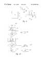
- a conventional system for retrieving, processing, and displaying a signal from a sensoris shown in FIG. 1.
- a sensor 10is connected to a cable 12 at a sensor terminal, and a connector 14 is attached adjacent to a signal terminal of the cable 12 .
- the signal terminalmay extend through the connector 14 or it may rest in a junction in the connector 14 which itself may transfer the signal.
- the cable 12includes a signal conduit between the sensor terminal and the signal terminal which may be an electrically conductive material or an arrangement of optical fibers.
- the connector 14is received by a receptacle 16 in an electronic instrument 18 such that the signal terminal and auxiliary terminals in the connector 14 are placed in electrical contact with circuitry inside the instrument 18 .
- the connector 14 and the receptacle 16may be joined by any suitable mechanical connection.
- the instrument 18includes a display 19 for displaying a processed representation of the signal.
- the display 19may be a tape display or a cathode ray tube or some other means of providing information.
- the system shown in FIG. 1operates in the following manner.
- the sensor 10generates a signal in response to a stimulus from a patient which is applied to the sensor terminal of the cable 12 .
- the signalmay be electrical or optical in nature.
- the signalis transferred by the signal conduit to the signal terminal of the cable 12 , and then to the circuitry in the instrument 18 through the connector 14 and the receptacle 16 .
- the signalis processed in the instrument 18 and presented in the display 19 according to methods appropriate for the particular signal.
- Modem operating roomsare crisscrossed by cables, each cable transmitting a signal from an individual sensor which is monitoring a parameter of the patient.
- Each cableis attached to its own instrument which is adapted to process and display the signal provided by the cable and its sensor. It is of critical importance that the cables and sensors be matched correctly with their corresponding instruments. If two cables were to be accidentally switched to the wrong instruments then the information displayed by those instruments would be meaningless and potentially misleading. The chances for an incorrect connection increase in an emergency when there is little time to carefully consider each connection.
- a system for identifying a cable transmitting a signal from a sensor to an electronic instrumentwhich permits a rapid identification of the cable.
- the cableincludes an elongated signal conduit extending between a sensor terminal adapted to be connected to the sensor and a signal terminal.
- a connectoris attached to the signal conduit adjacent to the signal terminal, and is attachable to the instrument to permit signal communication between the instrument and the sensor.
- a reactance elementsuch as a capacitor or an inductor is coupled between two or more terminals of the connector which are coupled to the instrument.
- the reactance elementas well as other cable identification components, may be packaged in the sensor, the sensor cable, and/or an adapter cable coupling the sensor to the instrument, as well as in connectors for those components.
- the instrumentincludes a measurement circuit adapted to measure characteristics of the reactance element.
- the instrumentincludes a microprocessor coupled to exchange signals with the measurement circuit. The microprocessor may also be coupled to the signal terminal to receive the signal from the sensor, and to generate information as a function of the signal.
- Various operating features or modesmay be selected in the electronic instrument depending upon the nature of the cable and/or sensor connected to the cable, as determined by the characteristics of the reactance element.
- a methodfor identifying a cable having a reactance element such as a capacitor or an inductor.
- a first voltageis provided to the reactance element, and a second voltage in the reactance element is monitored to detect a rate of change of the second voltage.
- the rate of change of the second voltageis compared to a predetermined rate and the cable is identified based on the comparison.
- the reactance elementis coupled to a bridge circuit and an alternating current signal is applied to the bridge circuit. An identification signal is generated when characteristics of the reactance element match predetermined characteristics.
- FIG. 1is a side view of a sensor, a cable, and an electronic instrument according to the prior art.
- FIG. 2is an electrical schematic diagram of a microprocessor and a connector with a capacitor joined by a resistive network and a trigger circuit according to the present invention.
- FIG. 3is an electrical schematic diagram of a microprocessor and a connector with a capacitor and a resistive network, the microprocessor joined to the connector by a conductive coupling and a trigger circuit according to the present invention.
- FIG. 4is a flowchart of a software routine carried out by the microprocessor of FIG. 2 for identifying a cable and processing a signal from a sensor according to the present invention.
- FIG. 5is a flowchart of an interrupt routine carried out by the microprocessor of FIG. 2 in response to a signal from the trigger circuit according to the present invention.
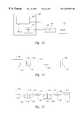
- FIG. 6is an electrical schematic diagram of a microprocessor and a connector with an inductor joined by a resistive network and a trigger circuit according to the present invention.
- FIG. 7is an electrical schematic diagram of a microprocessor and a connector with an inductor and a resistive network, the microprocessor joined to the connector by a conductive coupling and a trigger circuit according to the present invention.
- FIG. 8is an electrical schematic diagram of a microprocessor and a connector with a capacitor, a resistor, and a switch, the microprocessor joined to the connector by a conductive coupling and a current detection circuit according to the present invention.
- FIG. 9is an electrical schematic diagram of a microprocessor and a connector with a capacitor joined by a resistive coupling and a voltage detection circuit according to the present invention.
- FIG. 10is a flowchart of a software routine carried out by the microprocessor of FIG. 9 for identifying a cable and processing a signal from a sensor according to the present invention.
- FIG. 11is an electrical schematic diagram of a microprocessor and a connector with a capacitor and a resistor, the microprocessor joined to the connector by a bridge circuit according to the present invention.
- FIG. 12is an electrical schematic diagram of a connector with a capacitor coupled to a circuit for determining a rate of change of voltage across the capacitor according to the present invention.
- FIG. 13is a block diagram of a monitoring system including a monitor connected to a sensor through a cable in which an operating feature or mode is enabled as a function of the identity of the cable and/or sensor.
- FIG. 14is a block diagram of a monitoring system including a monitor connected to a sensor through a sensor cable showing the various locations in which reactive components and other cable identification components may be packaged.
- FIG. 15is a block diagram of a monitoring system including a monitor connected to a sensor through a sensor cable and an adapter cable showing the various locations in which reactive components and other cable identification components may be packaged.
- FIGS. 2, 3 , 6 - 9 , 11 , and 12Several examples of a system for identifying a cable according to the invention are shown in FIGS. 2, 3 , 6 - 9 , 11 , and 12 .
- Each exampleis shown as an electrical schematic diagram of a microprocessor and a connector joined by a circuit which are part of a larger system for providing information based on a signal from a sensor.
- the larger systemincludes the sensor, a cable, the connector, and an electronic instrument having a receptacle to which the connector is removably attached.
- the instrumenthouses the circuit, the microprocessor, and a display.
- the external structure of the sensor, the cable, the receptacle, the instrument, and the displayhave not been shown in detail in order not to unnecessarily obscure the invention.
- FIGS. 2, 3 , 6 - 9 , 11 , and 12presuppose that the connector is mechanically attached to the receptacle such that terminals in the connector are electrically coupled to the circuit in the instrument.
- a connector 20includes a capacitor 22 connected between two terminals 24 and 26 .
- the terminals 24 and 26are electrically coupled to adjoining terminals of a circuit 28 which includes a resistive network made up of two resistors 32 and 40 and a trigger circuit 36 .
- a microprocessor 30is coupled to the connector 20 through the circuit 28 .
- the resistor 32is coupled between the terminal 24 and a port 34 in the microprocessor 30 .
- the trigger circuit 36which may be a Shmitt trigger circuit, is coupled between a port 38 in the microprocessor 30 and the terminal 24 .
- the resistor 40is coupled between the terminals 24 and 26 , and the terminal 26 is coupled to a ground voltage reference.
- the capacitor 22provides the connector 20 with a reactance having an RC time constant which is unique for the combination of the capacitor 22 and the resistors 32 and 40 .
- the RC time constantgoverns a rate at which a voltage on the capacitor 22 changes when a voltage signal is applied to the combination of the capacitor 22 and the resistors 32 and 40 .
- the connector 20 and a cable attached to itmay be identified by the microprocessor 30 which determines the RC time constant by applying a voltage signal to the resistor 32 and monitoring the voltage on the capacitor 22 .
- capacitor 22is shown packaged in the connector 20 , it will be understood that it may alternatively be packaged in a cable (not shown) or sensor (not shown) attached to the connector 20 .
- a step function voltage signal or some other time-related voltage signalis provided by the microprocessor 30 from the port 34 to charge the capacitor 22 through the resistor 32 and the terminal 24 .
- the voltage on the capacitor 22is monitored at the terminal 24 by the trigger circuit 36 which provides a trigger signal to the port 38 when the voltage on the capacitor 22 reaches a predetermined threshold.
- the microprocessor 30determines an elapsed time between the application of the step function voltage signal and the trigger signal. The elapsed time is governed by the RC time constant. The microprocessor 30 then compares the elapsed time with a predetermined value to identify the cable as being correct or incorrect.
- the microprocessor 30terminates the step function voltage signal and the capacitor 22 discharges through the resistor 40 to the ground voltage reference. If the cable is identified as being the correct cable, then the microprocessor 30 may proceed to process a signal transmitted by the cable and send the results to a display. If the cable is identified as being incorrect, the microprocessor 30 may provide a message indicating such to the display.
- the capacitor 22is discharged to determine the RC time constant.
- the microprocessor 30provides a charging voltage from the port 34 to charge the capacitor 22 through the resistor 32 and the terminal 24 .
- the capacitor 22is charged to a selected voltage and the charging voltage is terminated.
- the capacitor 22discharges through the resistor 40 to the ground voltage reference while the voltage on the capacitor 22 is monitored at the terminal 24 by the trigger circuit 36 .
- the trigger circuit 36provides a trigger signal to the port 38 when the voltage on the capacitor 22 falls below a threshold.
- the microprocessor 30determines an elapsed time between the termination of the charging voltage and the trigger signal which is governed by the RC time constant.
- the microprocessor 30compares the elapsed time with a predetermined value to identify the cable as being correct or incorrect.
- FIG. 3An alternative system for identifying a cable according to another embodiment of the invention is shown in FIG. 3.
- a connector 44is coupled to a microprocessor 46 through a circuit 48 .
- the connector 44includes a capacitor 50 and two resistors 52 and 54 connected between three terminals 56 , 58 , and 60 which are electrically coupled to adjoining terminals of the circuit 48 .
- the capacitor 50 and the resistor 54are connected in parallel between the terminals 56 and 60
- the resistor 52is connected between the terminals 56 and 58 .
- the terminal 58is coupled to a port 62 in the microprocessor 46
- a trigger circuit 64is coupled between the terminal 56 and a port 66 in the microprocessor 46 .
- the terminal 60is coupled to a ground voltage reference.
- FIG. 3is similar to the system shown in FIG. 2 with the exception that a resistive network including the resistors 52 and 54 is located inside the connector 44 rather than between the connector 44 and the microprocessor 46 . Furthermore, all or some of the resistors 52 , 54 and the capacitor 50 may be packaged in a cable (not shown) or sensor (not shown) attached to the connector 44 .
- the system shown in FIG. 3identifies the connector 44 and a cable attached to it in a manner similar to the manner of identification described with respect to the system shown in FIG. 2 .
- FIG. 4is a flowchart of a software routine carried out by the microprocessor 30 shown in FIG. 2 to identify the connector 20 and a cable attached to it.
- the microprocessor 30identifies the cable according to the following steps.
- the microprocessor 30initiates the software routine with step 70 .
- the microprocessor 30initializes a time range with which to identify the connector 20 .
- the microprocessor 30applies a step function voltage signal from the port 34 to the capacitor 22 through the resistor 32 and the terminal 24 and simultaneously starts a counter.
- the microprocessor 30then executes a loop in the software routine beginning with step 76 until an interrupt routine occurs.
- a flowchart of the interrupt routineis shown in FIG. 5 .
- the microprocessor 30sets a flag when the trigger signal is received from the trigger circuit 36 at the port 38 . In other words, the flag is set when the voltage on the capacitor 22 reaches the threshold.
- the microprocessor 30reads a time from the counter.
- the microprocessor 30determines whether the interrupt routine has been executed. If the interrupt routine has not been executed, the microprocessor 30 determines in step 80 whether the time read from the counter in step 76 is greater than the time range initialized in step 72 .
- the microprocessor 30If the time read from the counter exceeds the time range, the cable is incorrect and the microprocessor 30 sends a cable error message to a display in step 82 .
- the microprocessor 30also terminates the step function voltage signal applied to the capacitor 22 and stops the counter in step 82 . If the time read from the counter does not exceed the time range then the microprocessor 30 returns from step 80 to read the time from the counter in step 76 .
- step 78the microprocessor 30 decides in step 84 whether the time read from the counter falls below the time range. If the time read from the counter is less than the time range, then the cable is incorrect and the microprocessor 30 sends a cable error message to the display in step 86 .
- the microprocessor 30also terminates the step function voltage signal applied to the capacitor 22 and stops the counter in step 86 .
- step 84the microprocessor 30 decides that the time read from the counter is within the time range, then the microprocessor 30 terminates the step function voltage signal applied to the capacitor 22 and stops the counter in step 88 .
- the microprocessor 30also processes a signal transmitted by the cable and sends the results to the display in step 88 .
- the microprocessor 30terminates the software routine in step 90 after either one of the steps 82 , 86 , or 88 have been executed.
- a connector 100includes an inductor 102 connected between two terminals 104 and 106 which are electrically coupled to adjoining terminals of a circuit 108 .
- a microprocessoris coupled to the connector 100 through the circuit 108 .
- the circuit 108includes a resistor 112 coupled between the terminal 104 and a port 116 in the microprocessor 110 .
- a trigger circuit 118is coupled between a port 120 of the microprocessor 110 and the terminal 104 .
- a resistor 122is coupled between the terminals 104 and 106 and the terminal 106 is coupled to a ground voltage reference.
- the system shown in FIG. 6is similar to the system shown in FIG. 2 with the exception that the inductor 102 provides a reactance in the connector 100 .
- the connector 100has an RL time constant which is unique for the combination of the inductor 102 and the resistors 112 and 122 .
- the RL time constantgoverns a rate at which a voltage on the inductor 102 changes when a voltage signal is applied to the combination of the inductor 102 and the resistors 112 and 122 .
- the connector 100 and a cable attached to itmay be identified by the microprocessor 110 which determines the RL time constant by applying a voltage signal to the resistor 112 and monitoring the voltage on the inductor 102 .
- the inductor 102is shown packaged in the connector 100 , it may alternatively be packaged in a cable (not shown) or sensor (not shown) attached to the connector 100 .
- a step function voltage signalis provided by the microprocessor 110 from the port 116 to charge the inductor 102 through the resistor 112 and the terminal 104 .
- a voltage on the inductor 102is monitored at the terminal 104 by the trigger circuit 118 , and decreases as a current in the inductor 102 rises in response to the application of the step function voltage signal.
- the trigger circuit 118provides a trigger signal to the port 120 .
- the microprocessor 110determines an elapsed time between the application of the step function voltage signal and the trigger signal which is governed by the RL time constant.
- the microprocessor 110then compares the elapsed time with a predetermined value to identify the cable as being correct or incorrect. Once the cable is identified the microprocessor 110 terminates the step function voltage signal and the inductor 102 discharges through the resistor 122 .
- FIG. 7An alternative system for identifying a cable according to another embodiment of the invention is shown in FIG. 7.
- a connector 130is coupled to a microprocessor 132 through a circuit 134 .
- the connector 130includes an inductor 136 and two resistors 138 and 140 connected between three terminals 142 , 144 , and 146 which are electrically coupled to adjoining terminals of the circuit 134 .
- the inductor 136 and the resistor 140are connected in parallel between the terminals 142 and 146 , and the resistor 138 is connected between the terminals 142 and 144 .
- the terminal 144is coupled to a port 148 in the microprocessor 132
- a trigger circuit 150is coupled between the terminal 142 and a port 152 in the microprocessor 132 .
- the terminal 146is coupled to a ground voltage reference.
- the system shown in FIG. 7is similar to the system shown in FIG. 6 with the exception that a resistive network including the resistors 138 and 140 is located inside the connector 130 rather than between the connector 130 and the microprocessor 132 .
- the resistors 138 and 140 and the inductor 136may alternatively be packaged in or distributed throughout a cable (not shown) or sensor (not shown) coupled to the connector 130 .
- the system shown in FIG. 7identifies the connector 130 and a cable attached to it in a manner similar to the manner of identification described with respect to the system shown in FIG. 6 .
- FIG. 8An alternative system for identifying a cable according to still another embodiment of the invention is shown in FIG. 8.
- a connector 160is coupled to a microprocessor 162 through a circuit 164 .
- the connectorincludes a resistor 166 and a capacitor 168 connected in series between two terminals 170 and 172 which are electrically coupled to adjoining terminals in the circuit 164 .
- An N-channel MOS transistor 174is connected between two terminals 176 and 178 which are also electrically coupled to adjoining terminals in the circuit 164 .
- a control terminal of the transistor 174is connected to a node between the resistor 166 and the capacitor 168 such that a voltage on the capacitor 168 is applied to the control terminal.
- the terminal 170is coupled to a port 180 in the microprocessor 162 , and the terminal 172 is coupled to a ground voltage reference.
- the parallel combination of a resistor 189 and a resistor 182 and a voltage source 184 connected in seriesare connected in series with a resistor 186 and the transistor 174 , which is connected between the terminal 176 and the terminal 178 .
- the junction between the resistor 182 and the resistor 186is connected to a port 188 in the microprocessor 162 .
- the transistor 174is used as a switch to control current in a circuit including the transistor 174 , the resistor 182 , the resistor 189 , the voltage source 184 , and the resistor 186 .
- the transistor 174is rendered conductive when the voltage on the capacitor 168 exceeds a threshold.
- the voltage at the junction between the resistor 182 , 186changes when the transistor 174 is rendered conductive, and this change is detected by the microprocessor 162 through the port 188 .
- the resistor 189may be omitted from the circuit 164 without substantially affecting its operation.
- the above-described cable identification componentsmay be packaged in or distributed throughout a cable (not shown) or sensor (not shown) coupled to the connector 160 .
- the connector 160 and a cable attached to itare identified in the following manner.
- a step function voltage signalis provided by the microprocessor 162 from the port 180 to charge the capacitor 168 through the terminal 170 and the resistor 166 .
- the voltage on the capacitor 168rises according to an RC time constant based on the capacitor 168 and the resistor 166 , and as it rises above the threshold, the transistor 174 is rendered conductive.
- the change in voltage at the node between resistors 182 , 186is then detected by the microprocessor 162 .
- the microprocessor 162determines an elapsed time between the application of the step function voltage signal and the change in voltage, which is governed by the RC time constant.
- the microprocessor 162compares the elapsed time with a predetermined value to identify the cable as being correct or incorrect.
- FIG. 9An alternative system for identifying a cable according to another embodiment of the invention is shown in FIG. 9.
- a connector 190is shown coupled to a microprocessor 192 through a circuit 194 .
- the connector 190includes a capacitor 196 connected between two terminals 198 and 200 which are electrically coupled to adjoining terminals in the circuit 194 .
- a resistor 202is coupled between the terminal 198 and a port 204 in the microprocessor 192 .
- the terminal 200is coupled to a ground voltage reference.
- the terminal 198is coupled to a control terminal of an N-channel MOS transistor 206 which is connected in series with a voltage source 208 , a current detection circuit 210 , and a resistor 212 .
- An output of the current detection circuit 210is connected to provide a trigger signal to a port 214 in the microprocessor 192 .
- an analog switch or another type of transistorsuch as a BJT or a JFET, may be substituted for the transistor 206 .
- the system shown in FIG. 9is similar to the system shown in FIG. 8 with the exception that the transistor 206 is located in the circuit 194 rather than in the connector 190 .
- the capacitormay, of course, be located either in a cable (not shown) or a sensor (not shown) coupled to the connector 190 .
- the system shown in FIG. 9identifies the connector 190 and a cable attached to it in a manner similar to the manner of identification described with respect to the system shown in FIG. 8 .
- FIG. 10is a flowchart of a software routine carried out by the microprocessors 162 or 192 of FIGS. 8 or 9 , respectively, to identify the connector and a cable attached to it.
- the microprocessor 192initiates the software routine in step 220 when the connector 190 is coupled to the circuit 194 .
- the microprocessor 192applies a step function voltage signal to the capacitor 196 through the resistor 202 and the terminal 198 and starts a timer in step 222 .
- the microprocessor 192executes a loop in the software routine including steps 224 and 226 until current is detected by the current detection circuit 210 and the trigger signal is provided to the port 214 .
- the microprocessor 192determines whether the trigger signal has been received in step 224 , and if it has not, a delay step 226 is executed before the microprocessor 192 returns to step 224 . If current is detected by the current detection circuit 210 then the microprocessor 192 stops the timer, stores the time accumulated by the timer, and terminates the step function voltage signal in step 228 . In step 230 , the microprocessor 192 determines whether the stored time is within a range which indicates that the connector 190 and the cable attached to it are correctly identified.
- step 232the microprocessor 192 sends a cable error message to a display in step 232 . If the stored time is within the range then the microprocessor 192 processes a signal transmitted by the cable and sends the results to a display in step 234 . When either step 232 or 234 has been executed, the microprocessor 192 terminates the software routine in step 236 .
- FIG. 11An alternative system for identifying a cable according to a further embodiment of the invention is shown in FIG. 11.
- a connector 250is shown coupled to a microprocessor 252 through a bridge circuit 254 .
- the connector 250includes a capacitor 256 and a resistor 258 connected in parallel between two terminals 260 and 262 which are electrically coupled to adjoining terminals in the bridge circuit 254 .
- the bridge circuit 254includes three impedance elements and a detection circuit connected between four nodes 264 , 266 , 268 , and 270 .
- a first impedance element 272is connected between the nodes 264 and 270
- a second impedance element 274is connected between the nodes 266 and 268
- a third impedance element 276is connected between the nodes 268 and 270 .
- the terminals 260 and 262are coupled to the nodes 264 and 266 , respectively.
- a detection circuit 278is connected between the nodes 266 and 270 , and has an output connected to a port 280 of the microprocessor 252 .
- the detection circuit 278provides a null signal to the microprocessor 252 through the port 280 when a null condition exists between the nodes 266 and 270 .
- the node 264is connected to a port 282 of the microprocessor 252
- the node 268is connected to a port 284 of the microprocessor 252 .
- Either the resistor 258 or the capacitor 256may be removed from the connector 250 and made a part of the bridge circuit 254 .
- some or all of the components of the bridge circuit 254may be located in either or both of a cable (not shown) or sensor (not shown) coupled to the connector 250 .
- the system shown in FIG. 11identifies the connector 250 and a cable attached to it in the following manner.
- the microprocessor 252applies an alternating current signal between the nodes 264 and 268 of the bridge circuit 254 through the ports 282 and 284 . If the impedance provided by the capacitor 256 and the resistor 258 in the connector 250 is the correct impedance then the bridge circuit 254 is in balance and the detection circuit 278 will register a null condition with a null signal provided to the port 280 of the microprocessor 252 . If the impedance is incorrect then the null signal will not be generated and, after a selected period of time, the microprocessor 252 will send a cable error message to a display. If the connector 250 is identified as being correct, the microprocessor 252 processes a signal transmitted by the cable and sends the results to the display.
- bridge circuitsfor evaluating different types of impedances.
- the particular arrangement of the capacitor 256 and the resistor 258 in the connector 250may be replaced by any combination of resistors and a capacitor or an inductor provided that the bridge circuit 254 is suitably modified to evaluate the impedance.
- other meansmay be used in place of the trigger circuit in the embodiments of FIGS. 2-3 and 6 - 7 to detect a predetermined voltage level.
- a voltage comparatormay be used.
- a timerelated characteristic of the reactance circuitmay be measured by means other than detecting a predetermined voltage.
- a differentiatormay be used to directly measure the rate of change of a voltage on the reactance circuit.
- a stimulus signal other than a step functionsuch as a voltage ramp, may be used.
- a connector 300is coupled to a circuit 302 for identifying the connector 300 and a cable attached to it.
- the connector 300includes a capacitor 304 connected between two terminals 306 and 308 which are electrically coupled to adjoining terminals in the circuit 302 .
- the circuit 302includes the following elements.
- a resistor 310is coupled between the terminals 306 and 308 , and the terminal 308 is coupled to a ground voltage reference.
- a control logic circuit 312includes an output which is coupled through a resistor 316 to the terminal 306 , and an input for receiving a control signal from a microprocessor 322 .
- the control logic circuit 312receives a clock signal from a clock signal source 318 , and provides a control signal to a counter 320 .
- the counter 320includes an output connected to the microprocessor 322 .
- the terminal 306is also coupled to an inverting input of a comparator 326 .
- a non-inverting input of the comparator 326is connected to a reference voltage 328 , and an output of the comparator 326 is provided to the microprocessor 322 and to an input of the control logic circuit 312 .
- some or all of the components of the circuit 302may be located in either or both of a cable (not shown) or sensor (not shown) coupled to the connector 300 .
- the system shown in FIG. 12identifies the connector 300 and a cable attached to it in the following manner.
- the control logic circuit 312receives a start signal from the microprocessor 322 and in response starts the counter 320 and provides a charging voltage to charge the capacitor 304 through the resistor 316 and the terminal 306 .
- a voltage on the capacitor 304is monitored by the comparator 326 through the terminal 306 .
- the comparator 326outputs a high signal to the microprocessor 322 and the control logic circuit 312 while the voltage on the capacitor 304 is less than the reference voltage 328 .
- the output of the comparator 326switches to a low signal which indicates to the microprocessor 322 and the control logic circuit 312 that the voltage on the capacitor 304 has reached a threshold.
- the control logic circuit 312terminates the charging voltage provided to the capacitor 304 and stops the counter 320 .
- the microprocessor 322may identify the cable by determining an RC time constant for the capacitor 304 and the resistors 310 and 316 according to the count provided by the counter 320 which indicates an elapsed time between the application of the charging voltage and the low signal received from the comparator 326 . Once the charging voltage is terminated the capacitor is discharged through the resistor 310 and the ground voltage reference.
- the various embodiments of a cable and/or sensor identification system in accordance with the inventionmay be used to enable or select an operating feature or mode of an electronic instrument to which the cable is connected.
- an electronic instrument 400is coupled through a cable 402 to a sensor 404 .
- the sensor 404may be a conventional pulse oximetry sensor, and the cable 402 may be of conventional design except that either the cable 402 or the sensor 404 contains a reactance element 406 and possibly other components, as described above with reference to FIGS. 2-12.
- the electronic instrument 400may be a pulse oximetry monitor, although it may monitor other physiological parameters when used with appropriate sensors other than the pulse oximetry sensor 404 .
- the instrument 400also includes cable identifying circuitry 410 in accordance with one of the embodiments of the invention described above.
- the cable identifying circuitry 410provides an ENABLE signal that is used in the electronic instrument 400 to enable or select one or more operating features or modes of the conventional components 408 .
- the ENABLE signalenables one or more of the artifact or noise rejecting algorithms described in the above-cited patents to Tien et al. In this manner, the operating features or modes of the electronic instrument 400 can be automatically enabled or selected depending upon a characteristic of the cable 402 or the sensor 404 connected to the cable 402 as identified by signals from the reactance element 406 .
- the reactive components and other circuitrymay be included in the connectors for the sensor or the sensor cable. Some of these cable identification components may also be included in an electronic device, such as a monitor, to which the sensor cable is connected. However, in a broader sense, the reactive components and other circuitry may be packaged in other configurations, as shown in FIGS. 14 and 15.
- an electronic instrument 500such as a pulse oximetry monitor, includes an instrument connector 502 that is coupled to a sensor cable 504 through a sensor cable connector 506 .
- the opposite end of the sensor cable 504is connected to a sensor 508 , such as a pulse oximetry sensor.
- the sensor 508may be detachably coupled to the sensor cable 504 through a connector (not shown) or the like.
- One or more reactive componentssuch as a capacitor or an inductor, as well a other cable identification components, are included in one or more of the following locations: as circuitry 520 in the sensor connector 506 , circuitry 522 in the sensor cable 504 , and/or circuitry 524 in the sensor 508 .
- circuitry 528may also be included as circuitry 528 in the instrument 500 or the instrument connector 502 .
- the only requirementis that one or more of these cable identification components must be included in the sensor cable 504 , sensor connector 506 , or sensor 508 so that the instrument 500 can identity the cable 504 , connector 506 , or sensor 508 .
- an electronic instrument 600is coupled to a sensor 602 through an adapter cable 604 and a sensor cable 606 .
- the adapter cable 604includes a first adapter connector 610 coupled to an instrument connector 612 , and a second adapter connector 616 coupled to a sensor connector 618 .
- One or more reactive components and other cable identification componentsare included in one or more of the following locations: as circuitry 630 in the first adapter connector 610 , circuitry 632 in the adapter cable 604 , circuitry 634 in the second adapter connector 616 , circuitry 636 in the sensor connector 618 , circuitry 638 in the sensor cable 606 , and/or circuitry 540 in the sensor 602 .
- Some, but not all, of the reactive components and other circuitrymay also be included in circuitry 644 in the instrument 600 and/or circuitry 648 in the instrument connector 612 .
- the only requirementis that one or more of these cable identification components must be included in a location other than the instrument 600 and connector 612 so that the instrument 600 can identify the adapter cable 604 and/or the sensor cable 606 and sensor 602 .
- the sensor connector 618 , sensor cable 606 , and sensor 602do not contain any of the cable identification components described above. Instead, the sensor 602 and its associated cable 606 and connector 618 are available from a variety of sources. However, the sensor 602 can still be identified by the instrument 600 because the adapter connector 616 is specifically adapted to mate with the sensor connector 618 , and the adapter cable 604 , the connector 610 , and/or the connector 616 contain one or more reactive components and possibly other circuitry that may be identified by the instrument 600 . Various other combinations may, of course, also be used.
- the resistors which provide a resistance for the RC time constant for a connectormay be located within the connector or in a circuit coupled to the connector.
- the reactance elementcan be physically located at the sensor and coupled to the connector through the cable. Numerous variations are well within the scope of this invention. Accordingly, the invention is not limited except as by the appended claims.
Landscapes
- Health & Medical Sciences (AREA)
- Physics & Mathematics (AREA)
- Life Sciences & Earth Sciences (AREA)
- Biomedical Technology (AREA)
- Medical Informatics (AREA)
- Biophysics (AREA)
- Pathology (AREA)
- Engineering & Computer Science (AREA)
- General Physics & Mathematics (AREA)
- Heart & Thoracic Surgery (AREA)
- Optics & Photonics (AREA)
- Molecular Biology (AREA)
- Surgery (AREA)
- Animal Behavior & Ethology (AREA)
- General Health & Medical Sciences (AREA)
- Public Health (AREA)
- Veterinary Medicine (AREA)
- Details Of Connecting Devices For Male And Female Coupling (AREA)
Abstract
Description
Claims (57)
Priority Applications (1)
| Application Number | Priority Date | Filing Date | Title |
|---|---|---|---|
| US09/289,792US6497659B1 (en) | 1999-04-09 | 1999-04-09 | System for identifying a cable transmitting a signal from a sensor to an electronic instrument |
Applications Claiming Priority (1)
| Application Number | Priority Date | Filing Date | Title |
|---|---|---|---|
| US09/289,792US6497659B1 (en) | 1999-04-09 | 1999-04-09 | System for identifying a cable transmitting a signal from a sensor to an electronic instrument |
Publications (1)
| Publication Number | Publication Date |
|---|---|
| US6497659B1true US6497659B1 (en) | 2002-12-24 |
Family
ID=23113123
Family Applications (1)
| Application Number | Title | Priority Date | Filing Date |
|---|---|---|---|
| US09/289,792Expired - Fee RelatedUS6497659B1 (en) | 1999-04-09 | 1999-04-09 | System for identifying a cable transmitting a signal from a sensor to an electronic instrument |
Country Status (1)
| Country | Link |
|---|---|
| US (1) | US6497659B1 (en) |
Cited By (79)
| Publication number | Priority date | Publication date | Assignee | Title |
|---|---|---|---|---|
| US20010041843A1 (en)* | 1999-02-02 | 2001-11-15 | Mark Modell | Spectral volume microprobe arrays |
| US20040167384A1 (en)* | 2003-02-20 | 2004-08-26 | Ge Medical Systems Information Technologies, Inc. | Patient monitoring system |
| US20040206914A1 (en)* | 2003-04-18 | 2004-10-21 | Medispectra, Inc. | Methods and apparatus for calibrating spectral data |
| US6847490B1 (en)* | 1997-01-13 | 2005-01-25 | Medispectra, Inc. | Optical probe accessory device for use in vivo diagnostic procedures |
| US20050074991A1 (en)* | 2003-10-03 | 2005-04-07 | Black William L. | Method and apparatus for determining a position of a location dependent device |
| US20060159734A1 (en)* | 2005-01-04 | 2006-07-20 | Jutaro Shudo | Topical patch cooling preparation and methods for using the same |
| US7127282B2 (en) | 1998-12-23 | 2006-10-24 | Medispectra, Inc. | Optical methods and systems for rapid screening of the cervix |
| US7136518B2 (en) | 2003-04-18 | 2006-11-14 | Medispectra, Inc. | Methods and apparatus for displaying diagnostic data |
| US7147347B1 (en) | 2004-09-09 | 2006-12-12 | Norire Khachakian | Flashing light cable |
| US7187810B2 (en) | 1999-12-15 | 2007-03-06 | Medispectra, Inc. | Methods and systems for correcting image misalignment |
| US7260248B2 (en) | 1999-12-15 | 2007-08-21 | Medispectra, Inc. | Image processing using measures of similarity |
| US20070232603A1 (en)* | 2006-02-15 | 2007-10-04 | Dendreon Corporation | Small-molecule modulators of TRP-P8 activity |
| US7282723B2 (en) | 2002-07-09 | 2007-10-16 | Medispectra, Inc. | Methods and apparatus for processing spectral data for use in tissue characterization |
| US7310547B2 (en) | 2002-07-10 | 2007-12-18 | Medispectra, Inc. | Fluorescent fiberoptic probe for tissue health discrimination |
| US7309867B2 (en) | 2003-04-18 | 2007-12-18 | Medispectra, Inc. | Methods and apparatus for characterization of tissue samples |
| CN100376209C (en)* | 2005-03-10 | 2008-03-26 | 深圳迈瑞生物医疗电子股份有限公司 | Method and device for fault diagnosis of blood oxygen sensor |
| US7377794B2 (en) | 2005-03-01 | 2008-05-27 | Masimo Corporation | Multiple wavelength sensor interconnect |
| US7469160B2 (en) | 2003-04-18 | 2008-12-23 | Banks Perry S | Methods and apparatus for evaluating image focus |
| US7509494B2 (en)* | 2002-03-01 | 2009-03-24 | Masimo Corporation | Interface cable |
| US7595723B2 (en) | 2005-11-14 | 2009-09-29 | Edwards Lifesciences Corporation | Wireless communication protocol for a medical sensor system |
| US7651492B2 (en) | 2006-04-24 | 2010-01-26 | Covidien Ag | Arc based adaptive control system for an electrosurgical unit |
| US7766693B2 (en) | 2003-11-20 | 2010-08-03 | Covidien Ag | Connector systems for electrosurgical generator |
| US20100241023A1 (en)* | 2009-03-19 | 2010-09-23 | Tyco Healthcare Group Lp | System and Method for Return Electrode Monitoring |
| US7834484B2 (en) | 2007-07-16 | 2010-11-16 | Tyco Healthcare Group Lp | Connection cable and method for activating a voltage-controlled generator |
| US7901400B2 (en) | 1998-10-23 | 2011-03-08 | Covidien Ag | Method and system for controlling output of RF medical generator |
| US7927328B2 (en) | 2006-01-24 | 2011-04-19 | Covidien Ag | System and method for closed loop monitoring of monopolar electrosurgical apparatus |
| US7947039B2 (en) | 2005-12-12 | 2011-05-24 | Covidien Ag | Laparoscopic apparatus for performing electrosurgical procedures |
| US7972328B2 (en) | 2006-01-24 | 2011-07-05 | Covidien Ag | System and method for tissue sealing |
| US7972332B2 (en) | 2006-03-03 | 2011-07-05 | Covidien Ag | System and method for controlling electrosurgical snares |
| US8025660B2 (en) | 2004-10-13 | 2011-09-27 | Covidien Ag | Universal foot switch contact port |
| US8080008B2 (en) | 2003-05-01 | 2011-12-20 | Covidien Ag | Method and system for programming and controlling an electrosurgical generator system |
| US8099250B2 (en) | 2005-08-02 | 2012-01-17 | Impedimed Limited | Impedance parameter values |
| US8096961B2 (en) | 2003-10-30 | 2012-01-17 | Covidien Ag | Switched resonant ultrasonic power amplifier system |
| US8105323B2 (en) | 1998-10-23 | 2012-01-31 | Covidien Ag | Method and system for controlling output of RF medical generator |
| US8147485B2 (en) | 2006-01-24 | 2012-04-03 | Covidien Ag | System and method for tissue sealing |
| US8187262B2 (en) | 2006-01-24 | 2012-05-29 | Covidien Ag | Dual synchro-resonant electrosurgical apparatus with bi-directional magnetic coupling |
| US8216220B2 (en) | 2007-09-07 | 2012-07-10 | Tyco Healthcare Group Lp | System and method for transmission of combined data stream |
| US8216223B2 (en) | 2006-01-24 | 2012-07-10 | Covidien Ag | System and method for tissue sealing |
| US8226639B2 (en) | 2008-06-10 | 2012-07-24 | Tyco Healthcare Group Lp | System and method for output control of electrosurgical generator |
| US8233974B2 (en) | 1999-06-22 | 2012-07-31 | Impedimed Limited | Method and device for measuring tissue oedema |
| US8231616B2 (en) | 2006-09-28 | 2012-07-31 | Covidien Ag | Transformer for RF voltage sensing |
| AU2006265762B2 (en)* | 2005-07-01 | 2012-08-16 | Impedimed Limited | Pulmonary monitoring system |
| US8287528B2 (en) | 1998-10-23 | 2012-10-16 | Covidien Ag | Vessel sealing system |
| US8486061B2 (en) | 2009-01-12 | 2013-07-16 | Covidien Lp | Imaginary impedance process monitoring and intelligent shut-off |
| US8487686B2 (en) | 2007-03-30 | 2013-07-16 | Impedimed Limited | Active guarding for reduction of resistive and capacitive signal loading with adjustable control of compensation level |
| US8512332B2 (en) | 2007-09-21 | 2013-08-20 | Covidien Lp | Real-time arc control in electrosurgical generators |
| US8523855B2 (en) | 2002-12-10 | 2013-09-03 | Covidien Ag | Circuit for controlling arc energy from an electrosurgical generator |
| US8548580B2 (en) | 2005-07-01 | 2013-10-01 | Impedimed Limited | Monitoring system |
| US8594781B2 (en) | 2007-01-15 | 2013-11-26 | Impedimed Limited | Monitoring system |
| US8647340B2 (en) | 2003-10-23 | 2014-02-11 | Covidien Ag | Thermocouple measurement system |
| US8663214B2 (en) | 2006-01-24 | 2014-03-04 | Covidien Ag | Method and system for controlling an output of a radio-frequency medical generator having an impedance based control algorithm |
| US8685016B2 (en) | 2006-01-24 | 2014-04-01 | Covidien Ag | System and method for tissue sealing |
| US8734438B2 (en) | 2005-10-21 | 2014-05-27 | Covidien Ag | Circuit and method for reducing stored energy in an electrosurgical generator |
| US20140145708A1 (en)* | 2012-11-28 | 2014-05-29 | Mediatek Inc. | Detecting circuit and related circuit detecting method |
| US8761870B2 (en) | 2006-05-30 | 2014-06-24 | Impedimed Limited | Impedance measurements |
| US8777941B2 (en) | 2007-05-10 | 2014-07-15 | Covidien Lp | Adjustable impedance electrosurgical electrodes |
| US8781544B2 (en) | 2007-03-27 | 2014-07-15 | Cercacor Laboratories, Inc. | Multiple wavelength optical sensor |
| US8801613B2 (en) | 2009-12-04 | 2014-08-12 | Masimo Corporation | Calibration for multi-stage physiological monitors |
| US8836345B2 (en) | 2007-11-05 | 2014-09-16 | Impedimed Limited | Impedance determination |
| US8965471B2 (en) | 2007-04-21 | 2015-02-24 | Cercacor Laboratories, Inc. | Tissue profile wellness monitor |
| US9149235B2 (en) | 2004-06-18 | 2015-10-06 | Impedimed Limited | Oedema detection |
| US9186200B2 (en) | 2006-01-24 | 2015-11-17 | Covidien Ag | System and method for tissue sealing |
| US9392947B2 (en) | 2008-02-15 | 2016-07-19 | Impedimed Limited | Blood flow assessment of venous insufficiency |
| US9474564B2 (en) | 2005-03-31 | 2016-10-25 | Covidien Ag | Method and system for compensating for external impedance of an energy carrying component when controlling an electrosurgical generator |
| US9486271B2 (en) | 2012-03-05 | 2016-11-08 | Covidien Lp | Method and apparatus for identification using capacitive elements |
| US9504406B2 (en) | 2006-11-30 | 2016-11-29 | Impedimed Limited | Measurement apparatus |
| US9585593B2 (en) | 2009-11-18 | 2017-03-07 | Chung Shing Fan | Signal distribution for patient-electrode measurements |
| US9615767B2 (en) | 2009-10-26 | 2017-04-11 | Impedimed Limited | Fluid level indicator determination |
| US9615766B2 (en) | 2008-11-28 | 2017-04-11 | Impedimed Limited | Impedance measurement process |
| US9636165B2 (en) | 2013-07-29 | 2017-05-02 | Covidien Lp | Systems and methods for measuring tissue impedance through an electrosurgical cable |
| US9724012B2 (en) | 2005-10-11 | 2017-08-08 | Impedimed Limited | Hydration status monitoring |
| US9839381B1 (en) | 2009-11-24 | 2017-12-12 | Cercacor Laboratories, Inc. | Physiological measurement system with automatic wavelength adjustment |
| US9872719B2 (en) | 2013-07-24 | 2018-01-23 | Covidien Lp | Systems and methods for generating electrosurgical energy using a multistage power converter |
| US10130382B2 (en) | 2014-03-27 | 2018-11-20 | Medtronic Xomed, Inc. | Powered surgical handpiece having a surgical tool with an RFID tag |
| US10307074B2 (en) | 2007-04-20 | 2019-06-04 | Impedimed Limited | Monitoring system and probe |
| JP2020012770A (en)* | 2018-07-19 | 2020-01-23 | 東亜ディーケーケー株式会社 | Measuring device and main device of measuring device |
| US11660013B2 (en) | 2005-07-01 | 2023-05-30 | Impedimed Limited | Monitoring system |
| US12029586B2 (en) | 2006-10-12 | 2024-07-09 | Masimo Corporation | Oximeter probe off indicator defining probe off space |
| US12226143B2 (en) | 2020-06-22 | 2025-02-18 | Covidien Lp | Universal surgical footswitch toggling |
Citations (12)
| Publication number | Priority date | Publication date | Assignee | Title |
|---|---|---|---|---|
| US4059797A (en)* | 1975-12-30 | 1977-11-22 | Office National D'etudes Et De Recherches Aerospatiales | A.C. capacitance measuring bridge |
| US4856530A (en)* | 1987-05-14 | 1989-08-15 | Becton, Dickinson And Company | Catheter identifier and method |
| US5184059A (en)* | 1991-09-16 | 1993-02-02 | Motorola, Inc. | Expanded battery capacity identification scheme and apparatus |
| US5654712A (en)* | 1995-08-02 | 1997-08-05 | Holtek Microelectronics Inc. | Encoding control device |
| US5660567A (en)* | 1995-11-14 | 1997-08-26 | Nellcor Puritan Bennett Incorporated | Medical sensor connector with removable encoding device |
| US5720293A (en)* | 1991-01-29 | 1998-02-24 | Baxter International Inc. | Diagnostic catheter with memory |
| US5779630A (en)* | 1993-12-17 | 1998-07-14 | Nellcor Puritan Bennett Incorporated | Medical sensor with modulated encoding scheme |
| US5987343A (en)* | 1997-11-07 | 1999-11-16 | Datascope Investment Corp. | Method for storing pulse oximetry sensor characteristics |
| US5995885A (en)* | 1995-04-07 | 1999-11-30 | Robert Bosch Gmbh | Method and arrangement for monitoring the detection of measured values in an electronic power control of a motor of a vehicle |
| US5997343A (en)* | 1998-03-19 | 1999-12-07 | Masimo Corporation | Patient cable sensor switch |
| US6064899A (en)* | 1998-04-23 | 2000-05-16 | Nellcor Puritan Bennett Incorporated | Fiber optic oximeter connector with element indicating wavelength shift |
| US6351658B1 (en)* | 1998-09-29 | 2002-02-26 | Mallinckrodt, Inc. | Multiple-code oximeter calibration element |
- 1999
- 1999-04-09USUS09/289,792patent/US6497659B1/ennot_activeExpired - Fee Related
Patent Citations (12)
| Publication number | Priority date | Publication date | Assignee | Title |
|---|---|---|---|---|
| US4059797A (en)* | 1975-12-30 | 1977-11-22 | Office National D'etudes Et De Recherches Aerospatiales | A.C. capacitance measuring bridge |
| US4856530A (en)* | 1987-05-14 | 1989-08-15 | Becton, Dickinson And Company | Catheter identifier and method |
| US5720293A (en)* | 1991-01-29 | 1998-02-24 | Baxter International Inc. | Diagnostic catheter with memory |
| US5184059A (en)* | 1991-09-16 | 1993-02-02 | Motorola, Inc. | Expanded battery capacity identification scheme and apparatus |
| US5779630A (en)* | 1993-12-17 | 1998-07-14 | Nellcor Puritan Bennett Incorporated | Medical sensor with modulated encoding scheme |
| US5995885A (en)* | 1995-04-07 | 1999-11-30 | Robert Bosch Gmbh | Method and arrangement for monitoring the detection of measured values in an electronic power control of a motor of a vehicle |
| US5654712A (en)* | 1995-08-02 | 1997-08-05 | Holtek Microelectronics Inc. | Encoding control device |
| US5660567A (en)* | 1995-11-14 | 1997-08-26 | Nellcor Puritan Bennett Incorporated | Medical sensor connector with removable encoding device |
| US5987343A (en)* | 1997-11-07 | 1999-11-16 | Datascope Investment Corp. | Method for storing pulse oximetry sensor characteristics |
| US5997343A (en)* | 1998-03-19 | 1999-12-07 | Masimo Corporation | Patient cable sensor switch |
| US6064899A (en)* | 1998-04-23 | 2000-05-16 | Nellcor Puritan Bennett Incorporated | Fiber optic oximeter connector with element indicating wavelength shift |
| US6351658B1 (en)* | 1998-09-29 | 2002-02-26 | Mallinckrodt, Inc. | Multiple-code oximeter calibration element |
Cited By (161)
| Publication number | Priority date | Publication date | Assignee | Title |
|---|---|---|---|---|
| US6847490B1 (en)* | 1997-01-13 | 2005-01-25 | Medispectra, Inc. | Optical probe accessory device for use in vivo diagnostic procedures |
| US9168089B2 (en) | 1998-10-23 | 2015-10-27 | Covidien Ag | Method and system for controlling output of RF medical generator |
| US9113900B2 (en) | 1998-10-23 | 2015-08-25 | Covidien Ag | Method and system for controlling output of RF medical generator |
| US8105323B2 (en) | 1998-10-23 | 2012-01-31 | Covidien Ag | Method and system for controlling output of RF medical generator |
| US7901400B2 (en) | 1998-10-23 | 2011-03-08 | Covidien Ag | Method and system for controlling output of RF medical generator |
| US8287528B2 (en) | 1998-10-23 | 2012-10-16 | Covidien Ag | Vessel sealing system |
| US7127282B2 (en) | 1998-12-23 | 2006-10-24 | Medispectra, Inc. | Optical methods and systems for rapid screening of the cervix |
| US20010041843A1 (en)* | 1999-02-02 | 2001-11-15 | Mark Modell | Spectral volume microprobe arrays |
| US8233974B2 (en) | 1999-06-22 | 2012-07-31 | Impedimed Limited | Method and device for measuring tissue oedema |
| US7187810B2 (en) | 1999-12-15 | 2007-03-06 | Medispectra, Inc. | Methods and systems for correcting image misalignment |
| US7260248B2 (en) | 1999-12-15 | 2007-08-21 | Medispectra, Inc. | Image processing using measures of similarity |
| US7509494B2 (en)* | 2002-03-01 | 2009-03-24 | Masimo Corporation | Interface cable |
| US7282723B2 (en) | 2002-07-09 | 2007-10-16 | Medispectra, Inc. | Methods and apparatus for processing spectral data for use in tissue characterization |
| US7310547B2 (en) | 2002-07-10 | 2007-12-18 | Medispectra, Inc. | Fluorescent fiberoptic probe for tissue health discrimination |
| US8005527B2 (en) | 2002-07-10 | 2011-08-23 | Luma Imaging Corporation | Method of determining a condition of a tissue |
| US8523855B2 (en) | 2002-12-10 | 2013-09-03 | Covidien Ag | Circuit for controlling arc energy from an electrosurgical generator |
| US7277743B2 (en)* | 2003-02-20 | 2007-10-02 | Ge Medical Systems Information Technologies, Inc. | Patient monitoring system |
| US20040167384A1 (en)* | 2003-02-20 | 2004-08-26 | Ge Medical Systems Information Technologies, Inc. | Patient monitoring system |
| US7469160B2 (en) | 2003-04-18 | 2008-12-23 | Banks Perry S | Methods and apparatus for evaluating image focus |
| US20040206914A1 (en)* | 2003-04-18 | 2004-10-21 | Medispectra, Inc. | Methods and apparatus for calibrating spectral data |
| US7459696B2 (en) | 2003-04-18 | 2008-12-02 | Schomacker Kevin T | Methods and apparatus for calibrating spectral data |
| US7136518B2 (en) | 2003-04-18 | 2006-11-14 | Medispectra, Inc. | Methods and apparatus for displaying diagnostic data |
| US7309867B2 (en) | 2003-04-18 | 2007-12-18 | Medispectra, Inc. | Methods and apparatus for characterization of tissue samples |
| US8303580B2 (en) | 2003-05-01 | 2012-11-06 | Covidien Ag | Method and system for programming and controlling an electrosurgical generator system |
| US8080008B2 (en) | 2003-05-01 | 2011-12-20 | Covidien Ag | Method and system for programming and controlling an electrosurgical generator system |
| US8267929B2 (en) | 2003-05-01 | 2012-09-18 | Covidien Ag | Method and system for programming and controlling an electrosurgical generator system |
| US8298223B2 (en) | 2003-05-01 | 2012-10-30 | Covidien Ag | Method and system for programming and controlling an electrosurgical generator system |
| US20050074991A1 (en)* | 2003-10-03 | 2005-04-07 | Black William L. | Method and apparatus for determining a position of a location dependent device |
| US7422440B2 (en)* | 2003-10-03 | 2008-09-09 | Lockheed Martin Corporation | Method and apparatus for determining a position of a location dependent device |
| US8647340B2 (en) | 2003-10-23 | 2014-02-11 | Covidien Ag | Thermocouple measurement system |
| US8485993B2 (en) | 2003-10-30 | 2013-07-16 | Covidien Ag | Switched resonant ultrasonic power amplifier system |
| US9768373B2 (en) | 2003-10-30 | 2017-09-19 | Covidien Ag | Switched resonant ultrasonic power amplifier system |
| US8966981B2 (en) | 2003-10-30 | 2015-03-03 | Covidien Ag | Switched resonant ultrasonic power amplifier system |
| US8113057B2 (en) | 2003-10-30 | 2012-02-14 | Covidien Ag | Switched resonant ultrasonic power amplifier system |
| US8096961B2 (en) | 2003-10-30 | 2012-01-17 | Covidien Ag | Switched resonant ultrasonic power amplifier system |
| US7766693B2 (en) | 2003-11-20 | 2010-08-03 | Covidien Ag | Connector systems for electrosurgical generator |
| US9149235B2 (en) | 2004-06-18 | 2015-10-06 | Impedimed Limited | Oedema detection |
| US7147347B1 (en) | 2004-09-09 | 2006-12-12 | Norire Khachakian | Flashing light cable |
| US8025660B2 (en) | 2004-10-13 | 2011-09-27 | Covidien Ag | Universal foot switch contact port |
| US20060159734A1 (en)* | 2005-01-04 | 2006-07-20 | Jutaro Shudo | Topical patch cooling preparation and methods for using the same |
| US12283374B2 (en) | 2005-03-01 | 2025-04-22 | Willow Laboratories, Inc. | Noninvasive multi-parameter patient monitor |
| US7729733B2 (en) | 2005-03-01 | 2010-06-01 | Masimo Laboratories, Inc. | Configurable physiological measurement system |
| US8050728B2 (en) | 2005-03-01 | 2011-11-01 | Masimo Laboratories, Inc. | Multiple wavelength sensor drivers |
| US9241662B2 (en) | 2005-03-01 | 2016-01-26 | Cercacor Laboratories, Inc. | Configurable physiological measurement system |
| US9167995B2 (en) | 2005-03-01 | 2015-10-27 | Cercacor Laboratories, Inc. | Physiological parameter confidence measure |
| US9131882B2 (en) | 2005-03-01 | 2015-09-15 | Cercacor Laboratories, Inc. | Noninvasive multi-parameter patient monitor |
| US7957780B2 (en) | 2005-03-01 | 2011-06-07 | Masimo Laboratories, Inc. | Physiological parameter confidence measure |
| US7377794B2 (en) | 2005-03-01 | 2008-05-27 | Masimo Corporation | Multiple wavelength sensor interconnect |
| US8130105B2 (en) | 2005-03-01 | 2012-03-06 | Masimo Laboratories, Inc. | Noninvasive multi-parameter patient monitor |
| US7563110B2 (en) | 2005-03-01 | 2009-07-21 | Masimo Laboratories, Inc. | Multiple wavelength sensor interconnect |
| US8190223B2 (en) | 2005-03-01 | 2012-05-29 | Masimo Laboratories, Inc. | Noninvasive multi-parameter patient monitor |
| US8929964B2 (en) | 2005-03-01 | 2015-01-06 | Cercacor Laboratories, Inc. | Multiple wavelength sensor drivers |
| US8912909B2 (en) | 2005-03-01 | 2014-12-16 | Cercacor Laboratories, Inc. | Noninvasive multi-parameter patient monitor |
| US8849365B2 (en) | 2005-03-01 | 2014-09-30 | Cercacor Laboratories, Inc. | Multiple wavelength sensor emitters |
| US9549696B2 (en) | 2005-03-01 | 2017-01-24 | Cercacor Laboratories, Inc. | Physiological parameter confidence measure |
| US8224411B2 (en) | 2005-03-01 | 2012-07-17 | Masimo Laboratories, Inc. | Noninvasive multi-parameter patient monitor |
| US11545263B2 (en) | 2005-03-01 | 2023-01-03 | Cercacor Laboratories, Inc. | Multiple wavelength sensor emitters |
| US9750443B2 (en) | 2005-03-01 | 2017-09-05 | Cercacor Laboratories, Inc. | Multiple wavelength sensor emitters |
| US11430572B2 (en) | 2005-03-01 | 2022-08-30 | Cercacor Laboratories, Inc. | Multiple wavelength sensor emitters |
| US7596398B2 (en) | 2005-03-01 | 2009-09-29 | Masimo Laboratories, Inc. | Multiple wavelength sensor attachment |
| US10123726B2 (en) | 2005-03-01 | 2018-11-13 | Cercacor Laboratories, Inc. | Configurable physiological measurement system |
| US8255027B2 (en) | 2005-03-01 | 2012-08-28 | Cercacor Laboratories, Inc. | Multiple wavelength sensor substrate |
| US8718735B2 (en) | 2005-03-01 | 2014-05-06 | Cercacor Laboratories, Inc. | Physiological parameter confidence measure |
| US8634889B2 (en) | 2005-03-01 | 2014-01-21 | Cercacor Laboratories, Inc. | Configurable physiological measurement system |
| US12230393B2 (en) | 2005-03-01 | 2025-02-18 | Willow Laboratories, Inc. | Multiple wavelength sensor emitters |
| US7764982B2 (en) | 2005-03-01 | 2010-07-27 | Masimo Laboratories, Inc. | Multiple wavelength sensor emitters |
| US10251585B2 (en) | 2005-03-01 | 2019-04-09 | Cercacor Laboratories, Inc. | Noninvasive multi-parameter patient monitor |
| US8301217B2 (en) | 2005-03-01 | 2012-10-30 | Cercacor Laboratories, Inc. | Multiple wavelength sensor emitters |
| US7761127B2 (en) | 2005-03-01 | 2010-07-20 | Masimo Laboratories, Inc. | Multiple wavelength sensor substrate |
| US10984911B2 (en) | 2005-03-01 | 2021-04-20 | Cercacor Laboratories, Inc. | Multiple wavelength sensor emitters |
| US8385996B2 (en) | 2005-03-01 | 2013-02-26 | Cercacor Laboratories, Inc. | Multiple wavelength sensor emitters |
| US8581732B2 (en) | 2005-03-01 | 2013-11-12 | Carcacor Laboratories, Inc. | Noninvasive multi-parameter patient monitor |
| US8483787B2 (en) | 2005-03-01 | 2013-07-09 | Cercacor Laboratories, Inc. | Multiple wavelength sensor drivers |
| US7647083B2 (en) | 2005-03-01 | 2010-01-12 | Masimo Laboratories, Inc. | Multiple wavelength sensor equalization |
| US10856788B2 (en) | 2005-03-01 | 2020-12-08 | Cercacor Laboratories, Inc. | Noninvasive multi-parameter patient monitor |
| US9351675B2 (en) | 2005-03-01 | 2016-05-31 | Cercacor Laboratories, Inc. | Noninvasive multi-parameter patient monitor |
| US10327683B2 (en) | 2005-03-01 | 2019-06-25 | Cercacor Laboratories, Inc. | Multiple wavelength sensor emitters |
| CN100376209C (en)* | 2005-03-10 | 2008-03-26 | 深圳迈瑞生物医疗电子股份有限公司 | Method and device for fault diagnosis of blood oxygen sensor |
| US11013548B2 (en) | 2005-03-31 | 2021-05-25 | Covidien Ag | Method and system for compensating for external impedance of energy carrying component when controlling electrosurgical generator |
| US9474564B2 (en) | 2005-03-31 | 2016-10-25 | Covidien Ag | Method and system for compensating for external impedance of an energy carrying component when controlling an electrosurgical generator |
| US8548580B2 (en) | 2005-07-01 | 2013-10-01 | Impedimed Limited | Monitoring system |
| US11660013B2 (en) | 2005-07-01 | 2023-05-30 | Impedimed Limited | Monitoring system |
| US11737678B2 (en) | 2005-07-01 | 2023-08-29 | Impedimed Limited | Monitoring system |
| AU2006265762B2 (en)* | 2005-07-01 | 2012-08-16 | Impedimed Limited | Pulmonary monitoring system |
| US8099250B2 (en) | 2005-08-02 | 2012-01-17 | Impedimed Limited | Impedance parameter values |
| US11612332B2 (en) | 2005-10-11 | 2023-03-28 | Impedimed Limited | Hydration status monitoring |
| US9724012B2 (en) | 2005-10-11 | 2017-08-08 | Impedimed Limited | Hydration status monitoring |
| US9522032B2 (en) | 2005-10-21 | 2016-12-20 | Covidien Ag | Circuit and method for reducing stored energy in an electrosurgical generator |
| US8734438B2 (en) | 2005-10-21 | 2014-05-27 | Covidien Ag | Circuit and method for reducing stored energy in an electrosurgical generator |
| US7595723B2 (en) | 2005-11-14 | 2009-09-29 | Edwards Lifesciences Corporation | Wireless communication protocol for a medical sensor system |
| US8241278B2 (en) | 2005-12-12 | 2012-08-14 | Covidien Ag | Laparoscopic apparatus for performing electrosurgical procedures |
| US7947039B2 (en) | 2005-12-12 | 2011-05-24 | Covidien Ag | Laparoscopic apparatus for performing electrosurgical procedures |
| US8663214B2 (en) | 2006-01-24 | 2014-03-04 | Covidien Ag | Method and system for controlling an output of a radio-frequency medical generator having an impedance based control algorithm |
| US8267928B2 (en) | 2006-01-24 | 2012-09-18 | Covidien Ag | System and method for closed loop monitoring of monopolar electrosurgical apparatus |
| US9642665B2 (en) | 2006-01-24 | 2017-05-09 | Covidien Ag | Method and system for controlling an output of a radio-frequency medical generator having an impedance based control algorithm |
| US8202271B2 (en) | 2006-01-24 | 2012-06-19 | Covidien Ag | Dual synchro-resonant electrosurgical apparatus with bi-directional magnetic coupling |
| US8187262B2 (en) | 2006-01-24 | 2012-05-29 | Covidien Ag | Dual synchro-resonant electrosurgical apparatus with bi-directional magnetic coupling |
| US7927328B2 (en) | 2006-01-24 | 2011-04-19 | Covidien Ag | System and method for closed loop monitoring of monopolar electrosurgical apparatus |
| US8147485B2 (en) | 2006-01-24 | 2012-04-03 | Covidien Ag | System and method for tissue sealing |
| US8216223B2 (en) | 2006-01-24 | 2012-07-10 | Covidien Ag | System and method for tissue sealing |
| US8685016B2 (en) | 2006-01-24 | 2014-04-01 | Covidien Ag | System and method for tissue sealing |
| US7972328B2 (en) | 2006-01-24 | 2011-07-05 | Covidien Ag | System and method for tissue sealing |
| US10582964B2 (en) | 2006-01-24 | 2020-03-10 | Covidien Lp | Method and system for controlling an output of a radio-frequency medical generator having an impedance based control algorithm |
| US9186200B2 (en) | 2006-01-24 | 2015-11-17 | Covidien Ag | System and method for tissue sealing |
| US8475447B2 (en) | 2006-01-24 | 2013-07-02 | Covidien Ag | System and method for closed loop monitoring of monopolar electrosurgical apparatus |
| US20070232603A1 (en)* | 2006-02-15 | 2007-10-04 | Dendreon Corporation | Small-molecule modulators of TRP-P8 activity |
| US7972332B2 (en) | 2006-03-03 | 2011-07-05 | Covidien Ag | System and method for controlling electrosurgical snares |
| US8556890B2 (en) | 2006-04-24 | 2013-10-15 | Covidien Ag | Arc based adaptive control system for an electrosurgical unit |
| US9119624B2 (en) | 2006-04-24 | 2015-09-01 | Covidien Ag | ARC based adaptive control system for an electrosurgical unit |
| US7651492B2 (en) | 2006-04-24 | 2010-01-26 | Covidien Ag | Arc based adaptive control system for an electrosurgical unit |
| US8761870B2 (en) | 2006-05-30 | 2014-06-24 | Impedimed Limited | Impedance measurements |
| US8231616B2 (en) | 2006-09-28 | 2012-07-31 | Covidien Ag | Transformer for RF voltage sensing |
| US12029586B2 (en) | 2006-10-12 | 2024-07-09 | Masimo Corporation | Oximeter probe off indicator defining probe off space |
| US9504406B2 (en) | 2006-11-30 | 2016-11-29 | Impedimed Limited | Measurement apparatus |
| US8594781B2 (en) | 2007-01-15 | 2013-11-26 | Impedimed Limited | Monitoring system |
| US8781544B2 (en) | 2007-03-27 | 2014-07-15 | Cercacor Laboratories, Inc. | Multiple wavelength optical sensor |
| US8487686B2 (en) | 2007-03-30 | 2013-07-16 | Impedimed Limited | Active guarding for reduction of resistive and capacitive signal loading with adjustable control of compensation level |
| US10307074B2 (en) | 2007-04-20 | 2019-06-04 | Impedimed Limited | Monitoring system and probe |
| US10980457B2 (en) | 2007-04-21 | 2021-04-20 | Masimo Corporation | Tissue profile wellness monitor |
| US12156733B2 (en) | 2007-04-21 | 2024-12-03 | Masimo Corporation | Tissue profile wellness monitor |
| US8965471B2 (en) | 2007-04-21 | 2015-02-24 | Cercacor Laboratories, Inc. | Tissue profile wellness monitor |
| US9848807B2 (en) | 2007-04-21 | 2017-12-26 | Masimo Corporation | Tissue profile wellness monitor |
| US10251586B2 (en) | 2007-04-21 | 2019-04-09 | Masimo Corporation | Tissue profile wellness monitor |
| US11647923B2 (en) | 2007-04-21 | 2023-05-16 | Masimo Corporation | Tissue profile wellness monitor |
| US8777941B2 (en) | 2007-05-10 | 2014-07-15 | Covidien Lp | Adjustable impedance electrosurgical electrodes |
| US8004121B2 (en) | 2007-07-16 | 2011-08-23 | Tyco Healthcare Group Lp | Connection cable and method for activating a voltage-controlled generator |
| US7834484B2 (en) | 2007-07-16 | 2010-11-16 | Tyco Healthcare Group Lp | Connection cable and method for activating a voltage-controlled generator |
| US8216220B2 (en) | 2007-09-07 | 2012-07-10 | Tyco Healthcare Group Lp | System and method for transmission of combined data stream |
| US8353905B2 (en) | 2007-09-07 | 2013-01-15 | Covidien Lp | System and method for transmission of combined data stream |
| US9271790B2 (en) | 2007-09-21 | 2016-03-01 | Coviden Lp | Real-time arc control in electrosurgical generators |
| US8512332B2 (en) | 2007-09-21 | 2013-08-20 | Covidien Lp | Real-time arc control in electrosurgical generators |
| US8836345B2 (en) | 2007-11-05 | 2014-09-16 | Impedimed Limited | Impedance determination |
| US9392947B2 (en) | 2008-02-15 | 2016-07-19 | Impedimed Limited | Blood flow assessment of venous insufficiency |
| US8226639B2 (en) | 2008-06-10 | 2012-07-24 | Tyco Healthcare Group Lp | System and method for output control of electrosurgical generator |
| US9615766B2 (en) | 2008-11-28 | 2017-04-11 | Impedimed Limited | Impedance measurement process |
| US8486061B2 (en) | 2009-01-12 | 2013-07-16 | Covidien Lp | Imaginary impedance process monitoring and intelligent shut-off |
| US8298225B2 (en) | 2009-03-19 | 2012-10-30 | Tyco Healthcare Group Lp | System and method for return electrode monitoring |
| US20100241023A1 (en)* | 2009-03-19 | 2010-09-23 | Tyco Healthcare Group Lp | System and Method for Return Electrode Monitoring |
| US9615767B2 (en) | 2009-10-26 | 2017-04-11 | Impedimed Limited | Fluid level indicator determination |
| US9585593B2 (en) | 2009-11-18 | 2017-03-07 | Chung Shing Fan | Signal distribution for patient-electrode measurements |
| US9839381B1 (en) | 2009-11-24 | 2017-12-12 | Cercacor Laboratories, Inc. | Physiological measurement system with automatic wavelength adjustment |
| US11534087B2 (en) | 2009-11-24 | 2022-12-27 | Cercacor Laboratories, Inc. | Physiological measurement system with automatic wavelength adjustment |
| US10750983B2 (en) | 2009-11-24 | 2020-08-25 | Cercacor Laboratories, Inc. | Physiological measurement system with automatic wavelength adjustment |
| US12127833B2 (en) | 2009-11-24 | 2024-10-29 | Willow Laboratories, Inc. | Physiological measurement system with automatic wavelength adjustment |
| US8801613B2 (en) | 2009-12-04 | 2014-08-12 | Masimo Corporation | Calibration for multi-stage physiological monitors |
| US12186079B2 (en) | 2009-12-04 | 2025-01-07 | Masimo Corporation | Calibration for multi-stage physiological monitors |
| US11571152B2 (en) | 2009-12-04 | 2023-02-07 | Masimo Corporation | Calibration for multi-stage physiological monitors |
| US10729402B2 (en) | 2009-12-04 | 2020-08-04 | Masimo Corporation | Calibration for multi-stage physiological monitors |
| US10278788B2 (en) | 2012-03-05 | 2019-05-07 | Covidien Lp | Method and apparatus for identification using capacitive elements |
| US9486271B2 (en) | 2012-03-05 | 2016-11-08 | Covidien Lp | Method and apparatus for identification using capacitive elements |
| US20140145708A1 (en)* | 2012-11-28 | 2014-05-29 | Mediatek Inc. | Detecting circuit and related circuit detecting method |
| US9588859B2 (en)* | 2012-11-28 | 2017-03-07 | Mediatek Inc. | Detecting circuit and related circuit detecting method |
| US11135001B2 (en) | 2013-07-24 | 2021-10-05 | Covidien Lp | Systems and methods for generating electrosurgical energy using a multistage power converter |
| US9872719B2 (en) | 2013-07-24 | 2018-01-23 | Covidien Lp | Systems and methods for generating electrosurgical energy using a multistage power converter |
| US9636165B2 (en) | 2013-07-29 | 2017-05-02 | Covidien Lp | Systems and methods for measuring tissue impedance through an electrosurgical cable |
| US9655670B2 (en) | 2013-07-29 | 2017-05-23 | Covidien Lp | Systems and methods for measuring tissue impedance through an electrosurgical cable |
| US10130382B2 (en) | 2014-03-27 | 2018-11-20 | Medtronic Xomed, Inc. | Powered surgical handpiece having a surgical tool with an RFID tag |
| US10987121B2 (en) | 2014-03-27 | 2021-04-27 | Medtronic Xomed, Inc. | Powered surgical handpiece having a surgical tool with an RFID tag |
| JP7071635B2 (en) | 2018-07-19 | 2022-05-19 | 東亜ディーケーケー株式会社 | Measuring device and main body of measuring device |
| JP2020012770A (en)* | 2018-07-19 | 2020-01-23 | 東亜ディーケーケー株式会社 | Measuring device and main device of measuring device |
| US12226143B2 (en) | 2020-06-22 | 2025-02-18 | Covidien Lp | Universal surgical footswitch toggling |
Similar Documents
| Publication | Publication Date | Title |
|---|---|---|
| US6497659B1 (en) | System for identifying a cable transmitting a signal from a sensor to an electronic instrument | |
| US5991355A (en) | Device for counting the number of uses of a sensor | |
| US7902810B2 (en) | Cable detection system | |
| EP0498303B1 (en) | Fertility probe | |
| US5781024A (en) | Instrument performance verification system | |
| US8109883B2 (en) | Cable monitoring apparatus | |
| US6792396B2 (en) | Interface device and method for a monitoring network | |
| US5939609A (en) | Multi-use sensor having a controllable number of measurement cycles | |
| EP2449964B1 (en) | Connector for Impedance Measurement System | |
| US5830129A (en) | Process and apparatus for measuring blood flow through an organ or other biological tissue | |
| US7911754B2 (en) | Detection of current leakage through opto-switches | |
| CN104188624B (en) | A kind of medical menitoring system of automatic identification sensor and method | |
| US10918336B2 (en) | Passive catheter identification and self-configuration system | |
| US5766133A (en) | Circuit for testing cables for physiological signal sensing electrodes | |
| US3910258A (en) | Cerebral activity monitor | |
| US5792185A (en) | Apparatus, method, and system which accurately discriminates between defibrillation electrodes and heart monitoring electrodes | |
| US20040005024A1 (en) | Apparatus and method for measuring current flow in an animal or human body | |
| US11555846B2 (en) | Testing electrode quality | |
| CA2295001C (en) | Instrument performance verification system | |
| CN214971179U (en) | Defibrillation electrode plate, defibrillation equipment and information prompting device | |
| US6026146A (en) | Automated voice terminal protocol identification system | |
| CN113679944A (en) | Detecting asymmetry in bidirectional semiconductor devices | |
| CN117647335A (en) | Electrode testing device | |
| AU2011232751B2 (en) | Monitoring system |
Legal Events
| Date | Code | Title | Description |
|---|---|---|---|
| AS | Assignment | Owner name:SPACELABS MEDICAL, INC., WASHINGTON Free format text:ASSIGNMENT OF ASSIGNORS INTEREST;ASSIGNOR:RAFERT, STEPHEN C.;REEL/FRAME:009894/0397 Effective date:19990212 | |
| AS | Assignment | Owner name:BANK OF AMERICA, N.A., CALIFORNIA Free format text:ASSIGNMENT OF ASSIGNORS INTEREST;ASSIGNORS:SPACELABS MEDICAL, INC.;SPACELABS, INC.;REEL/FRAME:012520/0423 Effective date:20020116 | |
| AS | Assignment | Owner name:LIFECLINIC MEDICAL DATA CORPORATION, WASHINGTON Free format text:RELEASE OF SECURITY INTEREST;ASSIGNOR:BANK OF AMERICA, N.A.;REEL/FRAME:013128/0729 Effective date:20020703 Owner name:LIFECLINIC.COM CORPORATION, WASHINGTON Free format text:RELEASE OF SECURITY INTEREST;ASSIGNOR:BANK OF AMERICA, N.A.;REEL/FRAME:013128/0729 Effective date:20020703 Owner name:SPACELABS BURDICK, INC., WASHINGTON Free format text:RELEASE OF SECURITY INTEREST;ASSIGNOR:BANK OF AMERICA, N.A.;REEL/FRAME:013128/0729 Effective date:20020703 Owner name:SPACELABS MEDICAL, INC., WASHINGTON Free format text:RELEASE OF SECURITY INTEREST;ASSIGNOR:BANK OF AMERICA, N.A.;REEL/FRAME:013128/0729 Effective date:20020703 Owner name:VITASTAT MEDICAL SERVICES, INC., WASHINGTON Free format text:RELEASE OF SECURITY INTEREST;ASSIGNOR:BANK OF AMERICA, N.A.;REEL/FRAME:013128/0729 Effective date:20020703 | |
| CC | Certificate of correction | ||
| AS | Assignment | Owner name:SPACELABS MEDICAL, LLC, CALIFORNIA Free format text:ASSIGNMENT OF ASSIGNORS INTEREST;ASSIGNOR:DATEX-OHMEDA, INC.;REEL/FRAME:016418/0873 Effective date:20040319 Owner name:DATEX-OHMEDA, INC., WISCONSIN Free format text:MERGER;ASSIGNOR:SPACELABS MEDICAL, INC.;REEL/FRAME:016418/0866 Effective date:20021216 Owner name:BANK OF THE WEST, A CALIFORNIA BANKING CORPORATION Free format text:SECURITY AGREEMENT;ASSIGNOR:SPACELABS MEDICAL, INC.;REEL/FRAME:016182/0797 Effective date:20050624 | |
| FPAY | Fee payment | Year of fee payment:4 | |
| AS | Assignment | Owner name:WACHOVIA BANK, NATIONAL ASSOCIATION, AS ADMINISTRA Free format text:NOTICE OF GRANT OF SECURITY INTEREST;ASSIGNOR:SPACELABS HEALTHCARE, LLC;REEL/FRAME:019679/0424 Effective date:20070727 | |
| AS | Assignment | Owner name:SPACELABS MEDICAL, INC., WASHINGTON Free format text:MERGER;ASSIGNOR:SPACELABS MEDICAL, LLC;REEL/FRAME:020134/0733 Effective date:20040323 | |
| AS | Assignment | Owner name:SPACELABS HEALTHCARE, LLC, WASHINGTON Free format text:NUNC PRO TUNC ASSIGNMENT;ASSIGNOR:SPACELABS MEDICAL, INC.;REEL/FRAME:020166/0907 Effective date:20071128 | |
| FEPP | Fee payment procedure | Free format text:PAYOR NUMBER ASSIGNED (ORIGINAL EVENT CODE: ASPN); ENTITY STATUS OF PATENT OWNER: LARGE ENTITY | |
| AS | Assignment | Owner name:SPACELABS MEDICAL, INC., WASHINGTON Free format text:TERMINATION OF SECURITY INTEREST IN PATENTS;ASSIGNOR:BANK OF THE WEST;REEL/FRAME:020638/0737 Effective date:20070727 | |
| FPAY | Fee payment | Year of fee payment:8 | |
| AS | Assignment | Owner name:WELLS FARGO BANK, NATIONAL ASSOCIATION, AS ADMINIS Free format text:NOTICE OF GRANT OF SECURITY INTEREST IN PATENTS;ASSIGNOR:SPACELABS HEALTHCARE, LLC;REEL/FRAME:025150/0956 Effective date:20070727 | |
| AS | Assignment | Owner name:SPACELABS HEALTHCARE, LLC, WASHINGTON Free format text:TERMINATION OF SECURITY INTEREST IN PATENTS;ASSIGNOR:WELLS FARGO BANK, NATIONAL ASSOCIATION, SUCCESSOR-BY-MERGER TO WACHOVIA BANK, NATIONAL ASSOCIATION, AS ADMINISTRATIVE AGENT;REEL/FRAME:025169/0269 Effective date:20101015 | |
| REMI | Maintenance fee reminder mailed | ||
| LAPS | Lapse for failure to pay maintenance fees | ||
| STCH | Information on status: patent discontinuation | Free format text:PATENT EXPIRED DUE TO NONPAYMENT OF MAINTENANCE FEES UNDER 37 CFR 1.362 | |
| FP | Lapsed due to failure to pay maintenance fee | Effective date:20141224 |