US6497573B2 - Composite dental abutment - Google Patents
Composite dental abutmentDownload PDFInfo
- Publication number
- US6497573B2 US6497573B2US09/977,773US97777301AUS6497573B2US 6497573 B2US6497573 B2US 6497573B2US 97777301 AUS97777301 AUS 97777301AUS 6497573 B2US6497573 B2US 6497573B2
- Authority
- US
- United States
- Prior art keywords
- core
- abutment
- shield
- cuff
- polymer
- Prior art date
- Legal status (The legal status is an assumption and is not a legal conclusion. Google has not performed a legal analysis and makes no representation as to the accuracy of the status listed.)
- Expired - Lifetime
Links
- 239000002131composite materialSubstances0.000titledescription2
- 229920000642polymerPolymers0.000claimsdescription36
- 239000007943implantSubstances0.000claimsdescription28
- 239000000463materialSubstances0.000claimsdescription23
- 239000000203mixtureSubstances0.000claimsdescription8
- 239000004053dental implantSubstances0.000claimsdescription7
- 229910052751metalInorganic materials0.000claimsdescription7
- 239000002184metalSubstances0.000claimsdescription7
- RTAQQCXQSZGOHL-UHFFFAOYSA-NTitaniumChemical compound[Ti]RTAQQCXQSZGOHL-UHFFFAOYSA-N0.000claimsdescription6
- 239000010936titaniumSubstances0.000claimsdescription6
- 229910052719titaniumInorganic materials0.000claimsdescription6
- 239000004593EpoxySubstances0.000claimsdescription3
- 229920000058polyacrylatePolymers0.000claimsdescription3
- 229920001187thermosetting polymerPolymers0.000claimsdescription3
- 229920001567vinyl ester resinPolymers0.000claimsdescription3
- 239000003999initiatorSubstances0.000claimsdescription2
- 229910001069Ti alloyInorganic materials0.000claims2
- 239000004634thermosetting polymerSubstances0.000claims2
- 239000004615ingredientSubstances0.000claims1
- 239000000919ceramicSubstances0.000description12
- 238000000034methodMethods0.000description9
- 229910052573porcelainInorganic materials0.000description8
- 230000008901benefitEffects0.000description5
- VYPSYNLAJGMNEJ-UHFFFAOYSA-NSilicium dioxideChemical compoundO=[Si]=OVYPSYNLAJGMNEJ-UHFFFAOYSA-N0.000description2
- 239000000853adhesiveSubstances0.000description2
- 230000001070adhesive effectEffects0.000description2
- 239000000956alloySubstances0.000description2
- 229910045601alloyInorganic materials0.000description2
- 229910010293ceramic materialInorganic materials0.000description2
- 239000003086colorantSubstances0.000description2
- 238000004519manufacturing processMethods0.000description2
- 230000013011matingEffects0.000description2
- 238000006116polymerization reactionMethods0.000description2
- 230000008569processEffects0.000description2
- 230000008439repair processEffects0.000description2
- 230000007704transitionEffects0.000description2
- PNEYBMLMFCGWSK-UHFFFAOYSA-Naluminium oxideInorganic materials[O-2].[O-2].[O-2].[Al+3].[Al+3]PNEYBMLMFCGWSK-UHFFFAOYSA-N0.000description1
- 210000000988bone and boneAnatomy0.000description1
- 239000004568cementSubstances0.000description1
- 230000001055chewing effectEffects0.000description1
- 239000000835fiberSubstances0.000description1
- 239000011521glassSubstances0.000description1
- 230000004048modificationEffects0.000description1
- 238000012986modificationMethods0.000description1
- TWNQGVIAIRXVLR-UHFFFAOYSA-Noxo(oxoalumanyloxy)alumaneChemical compoundO=[Al]O[Al]=OTWNQGVIAIRXVLR-UHFFFAOYSA-N0.000description1
- 239000000049pigmentSubstances0.000description1
- 239000002952polymeric resinSubstances0.000description1
- 229920005989resinPolymers0.000description1
- 239000011347resinSubstances0.000description1
- 239000000377silicon dioxideSubstances0.000description1
- 239000002904solventSubstances0.000description1
- 229920003002synthetic resinPolymers0.000description1
Images


Classifications
- A—HUMAN NECESSITIES
- A61—MEDICAL OR VETERINARY SCIENCE; HYGIENE
- A61C—DENTISTRY; APPARATUS OR METHODS FOR ORAL OR DENTAL HYGIENE
- A61C8/00—Means to be fixed to the jaw-bone for consolidating natural teeth or for fixing dental prostheses thereon; Dental implants; Implanting tools
- A61C8/0048—Connecting the upper structure to the implant, e.g. bridging bars
- A61C8/005—Connecting devices for joining an upper structure with an implant member, e.g. spacers
- A61C8/0054—Connecting devices for joining an upper structure with an implant member, e.g. spacers having a cylindrical implant connecting part
- A—HUMAN NECESSITIES
- A61—MEDICAL OR VETERINARY SCIENCE; HYGIENE
- A61C—DENTISTRY; APPARATUS OR METHODS FOR ORAL OR DENTAL HYGIENE
- A61C8/00—Means to be fixed to the jaw-bone for consolidating natural teeth or for fixing dental prostheses thereon; Dental implants; Implanting tools
- A61C8/0048—Connecting the upper structure to the implant, e.g. bridging bars
- A61C8/005—Connecting devices for joining an upper structure with an implant member, e.g. spacers
- A61C8/0059—Connecting devices for joining an upper structure with an implant member, e.g. spacers with additional friction enhancing means
- A—HUMAN NECESSITIES
- A61—MEDICAL OR VETERINARY SCIENCE; HYGIENE
- A61C—DENTISTRY; APPARATUS OR METHODS FOR ORAL OR DENTAL HYGIENE
- A61C8/00—Means to be fixed to the jaw-bone for consolidating natural teeth or for fixing dental prostheses thereon; Dental implants; Implanting tools
- A61C8/0048—Connecting the upper structure to the implant, e.g. bridging bars
- A61C8/005—Connecting devices for joining an upper structure with an implant member, e.g. spacers
- A61C8/0063—Connecting devices for joining an upper structure with an implant member, e.g. spacers with an internal sleeve
- A—HUMAN NECESSITIES
- A61—MEDICAL OR VETERINARY SCIENCE; HYGIENE
- A61C—DENTISTRY; APPARATUS OR METHODS FOR ORAL OR DENTAL HYGIENE
- A61C8/00—Means to be fixed to the jaw-bone for consolidating natural teeth or for fixing dental prostheses thereon; Dental implants; Implanting tools
- A61C8/0048—Connecting the upper structure to the implant, e.g. bridging bars
- A61C8/005—Connecting devices for joining an upper structure with an implant member, e.g. spacers
- A61C8/0069—Connecting devices for joining an upper structure with an implant member, e.g. spacers tapered or conical connection
Definitions
- FIG. 1shows a prior art dental restorative system described in U.S. Pat. No. 5,685,714 entitled “Support Post for Use in Dental Implant System.”
- the systemgenerally includes a dental implant 10 and a support post or abutment 12 .
- the implantis embedded into the jawbone leaving a gingival end 14 exposed through the bone.
- This gingival endincludes a threaded recess 15 and a multi-sided male projection 16 for abutting with the abutment 12 .
- the abutmenthas a cylindrical configuration with an elongated upper portion 18 and a lower transgingival portion 20 .
- the abutmentserves several functions but generally provides a structure for extending the implant above the gum-line. In this regard, one end of the abutment connects to implant while the other end connects to a prosthesis 22 .
- a passageway 24extends through the abutment and provides a recess 26 at the transgingival portion 20 for engaging the projection 16 of the implant.
- a screw 28abuts against a shoulder 30 and engages the threaded recess 15 to hold the abutment to the implant.
- the prosthesis 22is fabricated around the upper portion and typically connects to the abutment with either a separate screw (not shown) or cement.
- the abutmentis made of metal, such as titanium.
- An entirely metallic abutmentcan be visible through the prosthesis and can result in a dark, unattractive shadow within the prosthetic structure.
- the abutment shown in FIG. 1is made from two different materials.
- An outer portion 34is made from ceramic and an inner portion, shown as an insert 36 , is made from titanium or its alloys. The ceramic shields the shadow of the metallic abutment through the prosthesis.
- the restorative system shown in FIG. 1 and other prior abutmentspresent numerous disadvantages.
- the outer portion 34 of the abutmentis made of ceramic, typically aluminum oxide. Ceramic, however, is not always a desirable material for use in an abutment. Ceramics, for example, are very brittle and not easily repaired when damaged. If a ceramic component is damaged, for instance chipped, broken, or scratched, it is replaced with a new component. Furthermore, splinted, multiple-tooth ceramic prostheses are very difficult to fabricate because of the hard, brittle nature of the ceramic material. Ceramic components are also difficult to fabricate with precision because of the shrinkage of the ceramic that occurs as the ceramic material is sintered. Further yet, ceramics have a hardness even greater than that of titanium. Once these materials permanently harden, they cannot thereafter be softened and can be re-shaped only by grinding.
- the prosthesis 22is preferably made of porcelain.
- a porcelain prosthesisbonds well with a ceramic abutment but also is not always a desirable material. Like ceramic, porcelain cannot be easily repaired. If a porcelain prosthesis becomes chipped, for instance, it is replaced and typically not repaired. Additionally, porcelain also permanently hardens once cured. It cannot thereafter be softened and re-shaped. As a further disadvantage, porcelain has a hardness greater than natural teeth. As a result, a porcelain prosthesis will tend to wear an opposing natural tooth during chewing.
- the present inventionsolves the problems discussed above with prior dental restorative systems and provides further advantages.
- the present inventionis directed toward a dental restorative system having an abutment formed from two different materials.
- the abutmentincludes a metallic core and a polymeric cuff.
- the corehas a cylindrical configuration with an end abutting against a gingival end of a dental implant.
- the cuffsurrounds the outer surface of the core and connects to a prosthesis.
- the prosthesisis also formed from a polymer and bonds to or abuts the cuff.
- both the cuff of the abutment and the prosthesisare made from polymer. These components can be readily repaired if they become chipped, broken, or scratched. Such a repair may occur even after the polymer is hardened and the abutment and prosthesis are placed in the mouth of a patient.
- the polymeric prosthesisgenerally will not have a hardness greater than any opposing natural teeth in the patient. As such, the prosthesis will not wear or damage natural teeth as a porcelain prosthesis will.
- the polymeric cuffcan be made to more closely resemble the color of natural teeth than can the traditional metal abutments. As a result, the final restoration will have greatly improved esthetics.
- FIG. 1is a partial cross-sectional view of a prior art dental abutment connected to a prosthesis and implant;
- FIG. 2is a partial cross-sectional view of a dental restorative system according to the present invention.
- FIG. 3is cross-sectional view of another embodiment of a dental abutment
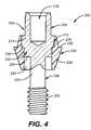
- FIG. 4is a cross-section view of yet another embodiment of a dental abutment
- FIGS. 5A-5Dare an illustration of a method of fabricating a dental prosthesis on a single dental implant abutment according to the present invention.
- FIGS. 6A-6Dare an illustration of a method of fabricating a dental prosthesis on multiple dental implant abutments according to the present invention.
- FIG. 7is a partial cross-sectional view of yet another embodiment of a dental abutment according to the present invention.
- FIG. 2shows a dental restorative system 100 that includes a prosthesis 102 , an abutment 104 , and an implant 106 .
- the abutment and prosthesisare attached together and connected to the implant as illustrated.
- Implant 106has a coronal or gingival end 108 with a threaded bore 110 and a male engaging feature 112 extending upwardly.
- the coronal endextends downwardly along a cylindrical body to a distal or apical end 114 .
- the engaging feature 112connects to the abutment and may be a plurality of upwardly extending tines, a polygon, or other type feature known to those skilled in the art.
- the implantmay have female engaging features that correspond with male projections on the abutment core.
- the implantmay be any one of various implants known in the art, such as those manufactured by Sulzer Calcitek Inc. of Carlsbad, Calif.
- the abutment 104has two different and distinct sections formed from two different materials.
- a core section 120has a cylindrical configuration and extends from a top portion 122 to a bottom portion 124 .
- a passageway 126extends centrally through the core.
- the bottom portion 124abuts against the coronal end 108 of the implant.
- this bottom portionmay be provided with an engaging feature 128 that engages with the engaging feature 112 to provide an anti-rotational connection between the abutment and implant.
- the engaging featureswould have matching configurations to provide the noted anti-rotational connection.
- engaging feature 112is a male hexagonal projection
- engaging feature 128would be a female hexagonal recess.
- the male and female counterpartsmay be located on either the abutment or implant and numerous configurations of engaging features known to those skilled in the art (such as spline tines, octagons, and other polygons) may be used.
- the corealso includes a shoulder 130 located along the interior of the passageway 126 at the top portion 122 .
- a corresponding ledge 132is formed along the exterior surface adjacent the shoulder 130 .
- the coreis made from a biocompatible metal, such as titanium or its alloys. The metallic core provides strength to the abutment and a framework for connecting the prosthesis to the implant.
- a cuff section 140connects to the exterior surface of the core 120 and, preferably, surrounds the entire exterior surface.
- the cuffhas a somewhat cylindrical configuration and extends from an upper portion 142 to a lower portion 144 .
- the cuffcan be shaped around the core to have various configurations, such as a cylindrical or elliptical configuration or an anatomical shape that resembles the cross section of a natural tooth.
- the lower portion 144tapers outwardly away from the coronal end 108 of the implant and forms a frusto-conical shape. This tapering continues to a ledge 146 and then transitions to taper inwardly at the upper portion 142 .
- a shoulder 148is located along the inner surface. This shoulder 148 fits with the mating ledge 132 on the exterior of the core.
- the prosthesis 102is shaped as a natural tooth and includes a passageway 150 that aligns with the passageway 126 of the abutment.
- a screw 152passes into these passageways until a head 154 of the screw abuts against the top portion 122 of the core.
- the lower portion of the headincludes a taper 156 that abuts against the shoulder 130 along the interior of the core.
- the screwincludes a shank 158 extending from the head. This shank has a threaded portion 160 that fits into the coronal end 108 of the implant to engage corresponding threads in threaded bore 110 .
- the screwholds the abutment and attached prosthesis to the implant.
- the head 154also includes a recess 162 . The recess may be provided to engage a tool (not shown) for tightening and loosening the screw or provided to threadable engage another screw (not shown) to secure the prosthesis.
- the cuff 140 of the abutment and the prosthesis 102are both made from polymeric materials.
- Various polymers and polymer combinations of polymersare suitable and known to those skilled in the art. Examples of such polymers include: acrylic polymers; fiber, glass, silica, and alumina reinforced polymers; thermosetting and photosensitive polymers; vinylesters; and epoxy type materials. Suitable polymers are sold under trademarks such as Sculpture® or FibreKor® of Jeneric/Pentron, Inc. or Targis® or Vectris® of Ivoclar, Inc.
- the polymeric cuff section of the abutmentprovides numerous advantages. First, a polymeric abutment or prosthesis can be repaired if damaged. Some polymers, for example, can be softened and re-shaped even after they harden. Further, additional polymeric material can be added to the existing structure if a repair is necessary. As another advantage, the polymer in the cuff can bond with the polymer in the prosthesis to form an integrated prosthetic unit. This unit would include the combination of the prosthesis and the abutment.
- FIG. 3shows an alternate embodiment for an abutment 178 within the scope of the invention.
- the core 180 and screw 182are similar to those described in FIG. 2 .
- the polymer cuff 184has an upper portion 186 that extends substantially above the top portion 188 of the core.
- This upper portion 186has an elongated cylindrical or elliptical configuration for attaching to a polymeric prosthesis.
- An optional shelf 190extends around the exterior of the cuff near the lower portion 192 . This shelf provides a support for building the prosthesis directly onto the abutment. Thus, the prosthesis bonds directly to the cuff.
- FIG. 4another alternate embodiment, shows an abutment 200 that has a single core device 202 .
- This corefunctions as both the core and screw shown in FIG. 2
- Core 202has a top portion 204 and a bottom portion 206 .
- the top portionincludes a bottom surface 208 that abuts against the coronal end of the implant (described in connection with FIG. 2 ).
- the bottom surfaceis not configured to engage the anti-rotational features (e.g:, spline tines, polygons) of the implant. Instead, the bottom portion abuts against the gingival end of the implant and is rotatable about this end.
- This type of connection between the implant and abutmentis primarily used in multiple tooth dental restorations.
- the top portion 204includes a ledge 212 located above the bottom surface and further includes a head portion 214 with a recess 216 .
- This recessserves a similar function to the recess described in connection with FIG. 2 .
- the bottom portionincludes a shank 220 extending from the top portion.
- This shankhas a threaded portion 222 that fits into the coronal end of the implant to engage a corresponding threaded bore (as shown in FIG. 2 ).
- the abutment 200also includes a cuff section 230 .
- This cuffsurrounds a portion of the exterior surface of the top portion 204 .
- the outer surface of the upper head portion 214is not covered.
- the cuffhas a somewhat cylindrical configuration and extends from an upper portion 232 to a lower portion 234 .
- This lower portiontapers outwardly and forms a frusto-conical shape.
- This taperingcontinues to a ledge 236 and then transitions to taper inwardly at the upper portion 232 .
- a shoulder 238is located along the inner surface. This shoulder 238 fits with the mating ledge 212 on the exterior of the core.
- the cuffcould also have other configurations, such as those described in connection with FIG. 2 .
- the lower portion 234 of the cuffextends below the bottom surface 208 of the core.
- a cavity 240thus forms below the bottom surface between the shank 220 and the lower portion. This cavity receives the coronal end of an implant.
- the lower portion 234may, optionally, not extend below the bottom surface 208 of the core such that no cavity 240 is present.
- FIGS. 5A-5Dillustrate a method for fabricating a polymeric dental prosthesis on a polymeric abutment. This method, for example, could be used to fabricate a polymeric prosthesis to be used in a single tooth dental restoration.
- FIG. 5Aillustrates the abutment 178 described in connection with FIG. 3 .
- the external polymeric cuff 184surrounds the internal metal core 180 (not visible).
- the abutment screw 182has been temporarily removed. Although the abutment described in FIG. 3 is used, it will be appreciated that any abutment within the scope of this invention could be used as well.
- the shape of the abutmentmay need to be modified. Typical modifications include cutting the abutment to a shorter height or grinding the abutment to a new shape. In FIG. 5B, the abutment 178 has been cut to reduce its overall height.
- a polymer 250is being applied around the outer surface of the cuff of the abutment. This polymer is being placed directly onto the cuff of the abutment as the prosthesis is being built. This process continues until the desired size and shape of the prosthesis is obtained.
- the desired shapecan be obtained, for example, by applying and contouring multiple layers of the polymer.
- the polymeric material in the cuff 184 and polymer 250bond directly to each other and create a strong, integrated composition.
- Various polymerscan be used to build the prosthesis.
- the composition of the cuff 184 and polymer 250may be the same material, similar materials, or different materials that are compatible for building dental restorations.
- light or heatis used to catalyze polymerization.
- the prosthesismay be colored to enhance esthetics and more closely match surrounding teeth.
- the prosthesis 252is complete and has a size and shape of a natural occurring tooth.
- the prosthesis 252includes a bore 254 for passage of the screw 182 described in FIG. 3 .
- FIGS. 5A-5Dillustrate a method for building the prosthesis directly onto the polymeric abutment.
- the prosthesiscould be formed separately (i.e., not directly on the abutment) using a curable polymeric resin.
- the prosthesiswould be formed with a passageway extending longitudinally through the body of the prosthesis.
- the prosthesiswould be shaped as a natural tooth and then the resin cured. Thereafter, the abutment would be inserted into the passageway.
- the abutment and prosthesiscould be attached using various techniques known to those skilled in the art, such as applying an adhesive or solvent around the cuff of the abutment or along the passageway of the prosthesis. Once the adhesive cured, the prosthesis would be affixed to the implant.
- FIGS. 6A-6Dillustrate another method for fabricating multiple polymeric dental prosthesis on polymeric abutments. This method, for example, could be used to fabricate prostheses to be used in a multiple tooth, multiple implant-borne dental restorations.
- FIG. 6Aillustrates two abutments 178 described in connection with FIG. 3 .
- the external polymeric cuff 184surrounds the internal metal core 180 (not visible).
- the abutment screw 182has been temporarily removed. Although the abutment described in FIG. 3 is used, it will be appreciated that any abutment within the scope of this invention could be used as well.
- the abutments 178have been cut to reduce their overall height. Further, they are placed adjacent each other and splinted together. Preferably, the abutments are splinted together with a polymeric framework 260 .
- the frameworkattaches to the outer surface of the cuff and is preferably made from a reinforced polymer. This polymer preferably would directly bond to the cuffs.
- various meansmay be used (such as light or heat) to catalyze polymerization.
- a polymer 262is being applied around the outer surface of the cuffs and framework. This polymer is being placed directly onto the cuff of the abutment and framework as the prosthesis is being built. This process continues until the desired size and shape of each prosthesis is obtained.
- the desired shapecan be obtained, for example, by applying and contouring multiple layers of the polymer.
- the polymeric material in the cuff 184 , framework 260 , and polymer 262bond directly to each other and create a strong, integrated composition.
- Various polymerscan be used to build the prosthesis.
- the composition of the cuff 184 , framework 260 , and polymer 262may be the same material, similar materials, or different materials that are compatible for building dental restorations.
- the multiple prosthesismay be colored to enhance esthetics and more closely match naturally occurring teeth.
- FIG. 6Dtwo prosthesis 266 are complete and have a size and shape of a two natural occurring teeth.
- Each prosthesisincludes a bore 268 for passage of the screw 182 described in FIG. 3 .
- FIG. 7shows another alternate embodiment for an abutment 270 within the scope of the invention.
- the core 272 , cuff 274 , and screw 276are similar to those described in FIGS. 2 and 3.
- a shield 278is added.
- this shieldextends around the entire outer surface 280 of the core 272 and is formed from an opaque material (as known as opaquers).
- the shield 278masks or hides the core and, in particular, any grayish or metallic color of the core. As such, the abutment 270 is esthetic since unsightly colors or shades of the core are not visible through the cuff 274 .
- the opaque materialis a mixture of several mono and dimethacrylates activated with light initiators. Pigments may be added to the opaque material to provide a variety of colors to best shield or mask the core.
Landscapes
- Health & Medical Sciences (AREA)
- Oral & Maxillofacial Surgery (AREA)
- Orthopedic Medicine & Surgery (AREA)
- Dentistry (AREA)
- Epidemiology (AREA)
- Life Sciences & Earth Sciences (AREA)
- Animal Behavior & Ethology (AREA)
- General Health & Medical Sciences (AREA)
- Public Health (AREA)
- Veterinary Medicine (AREA)
- Dental Prosthetics (AREA)
Abstract
Description
Claims (10)
Priority Applications (1)
| Application Number | Priority Date | Filing Date | Title |
|---|---|---|---|
| US09/977,773US6497573B2 (en) | 1998-07-30 | 2001-10-15 | Composite dental abutment |
Applications Claiming Priority (3)
| Application Number | Priority Date | Filing Date | Title |
|---|---|---|---|
| US12611798A | 1998-07-30 | 1998-07-30 | |
| US79922401A | 2001-03-05 | 2001-03-05 | |
| US09/977,773US6497573B2 (en) | 1998-07-30 | 2001-10-15 | Composite dental abutment |
Related Parent Applications (2)
| Application Number | Title | Priority Date | Filing Date |
|---|---|---|---|
| US12611798AContinuation-In-Part | 1998-07-30 | 1998-07-30 | |
| US79922401AContinuation-In-Part | 1998-07-30 | 2001-03-05 |
Publications (2)
| Publication Number | Publication Date |
|---|---|
| US20020076673A1 US20020076673A1 (en) | 2002-06-20 |
| US6497573B2true US6497573B2 (en) | 2002-12-24 |
Family
ID=26824305
Family Applications (1)
| Application Number | Title | Priority Date | Filing Date |
|---|---|---|---|
| US09/977,773Expired - LifetimeUS6497573B2 (en) | 1998-07-30 | 2001-10-15 | Composite dental abutment |
Country Status (1)
| Country | Link |
|---|---|
| US (1) | US6497573B2 (en) |
Cited By (39)
| Publication number | Priority date | Publication date | Assignee | Title |
|---|---|---|---|---|
| USD477667S1 (en) | 2002-08-05 | 2003-07-22 | George M. Whitehead | Dental abutment |
| USD477876S1 (en) | 2002-08-05 | 2003-07-29 | George M. Whitehead | Dental abutment |
| USD477879S1 (en) | 2002-08-05 | 2003-07-29 | George M. Whitehead | Dental abutment |
| USD477878S1 (en) | 2002-08-05 | 2003-07-29 | George M. Whitehead | Dental abutment |
| USD477877S1 (en) | 2002-08-05 | 2003-07-29 | George M. Whitehead | Dental abutment |
| USD482450S1 (en) | 2002-08-05 | 2003-11-18 | George M. Whitehead | Dental abutment |
| US20050084819A1 (en)* | 2003-10-20 | 2005-04-21 | Sims Lawrence O. | Abutment system and method for preparing the same |
| US20050084821A1 (en)* | 2003-10-20 | 2005-04-21 | Sims Lawrence O. | Abutment system |
| US20050090826A1 (en)* | 2003-01-23 | 2005-04-28 | Waldemar Link (Gmbh & Co.) | Medical implant with a secured bone screw |
| US20050202368A1 (en)* | 2004-03-12 | 2005-09-15 | Robert Ganley | Abutment for dental implant |
| US20050244789A1 (en)* | 2004-04-30 | 2005-11-03 | Crohin Constant C | Aesthetic dental implant fixture and abutment system |
| US20070141532A1 (en)* | 2005-12-20 | 2007-06-21 | Ford Christopher W | Force distributing dental implant assembly |
| US20070141533A1 (en)* | 2005-12-20 | 2007-06-21 | Ford Christopher W | Polymeric dental implant assembly |
| US20080254414A1 (en)* | 2007-04-10 | 2008-10-16 | Mcguire James A | Dental abutment blank with preformed passage |
| US20080274440A1 (en)* | 2004-03-12 | 2008-11-06 | Ivoclar Vivadent Ag | Dental Implant Abutment |
| US20090197218A1 (en)* | 2008-02-05 | 2009-08-06 | Joseph Wiener | Universal transitional abutment |
| US8011926B2 (en) | 2008-05-15 | 2011-09-06 | Ford Christopher W | Polymeric dental implant assembly |
| US8075312B2 (en) | 2005-08-30 | 2011-12-13 | Zimmer Dental, Inc. | Dental implant with improved osseointegration features |
| US20120077149A1 (en)* | 2010-09-29 | 2012-03-29 | Ivoclar Vivadent Ag | Dental Implant System |
| US8231387B2 (en) | 2008-07-02 | 2012-07-31 | Zimmer, Inc. | Porous implant with non-porous threads |
| US8425231B1 (en) | 2012-01-23 | 2013-04-23 | Mark N. Hochman | Soft-tissue preservation temporary (shell) immediate-implant abutment method and device |
| US8562348B2 (en) | 2008-07-02 | 2013-10-22 | Zimmer Dental, Inc. | Modular implant with secured porous portion |
| US8562346B2 (en) | 2005-08-30 | 2013-10-22 | Zimmer Dental, Inc. | Dental implant for a jaw with reduced bone volume and improved osseointegration features |
| US8602782B2 (en) | 2009-11-24 | 2013-12-10 | Zimmer Dental, Inc. | Porous implant device with improved core |
| US8814567B2 (en) | 2005-05-26 | 2014-08-26 | Zimmer Dental, Inc. | Dental implant prosthetic device with improved osseointegration and esthetic features |
| US8851891B2 (en) | 2008-11-06 | 2014-10-07 | Zimmer Dental, Inc. | Expandable bone implant |
| US8882506B2 (en) | 2010-08-17 | 2014-11-11 | Warsaw Orthopedic, Inc. | Implant repair system and method |
| US8899982B2 (en) | 2008-07-02 | 2014-12-02 | Zimmer Dental, Inc. | Implant with structure for securing a porous portion |
| US9095396B2 (en) | 2008-07-02 | 2015-08-04 | Zimmer Dental, Inc. | Porous implant with non-porous threads |
| US9149345B2 (en) | 2007-08-30 | 2015-10-06 | Zimmer Dental, Inc. | Multiple root implant |
| US9271811B1 (en) | 2003-02-27 | 2016-03-01 | Philip Scott Lyren | Method for forming a dental implant with porous body |
| US9452032B2 (en) | 2012-01-23 | 2016-09-27 | Biomet 3I, Llc | Soft tissue preservation temporary (shell) immediate-implant abutment with biological active surface |
| US9474588B2 (en) | 2012-01-23 | 2016-10-25 | Biomet 3I, Llc | Method and apparatus for recording spatial gingival soft tissue relationship to implant placement within alveolar bone for immediate-implant placement |
| JP2016193266A (en)* | 2016-07-22 | 2016-11-17 | 中島 康 | Dental implant |
| US20160338802A1 (en)* | 2014-02-11 | 2016-11-24 | Heraeus Kulzer Gmbh | Dampening insert for dental implants |
| US9700390B2 (en) | 2014-08-22 | 2017-07-11 | Biomet 3I, Llc | Soft-tissue preservation arrangement and method |
| US9707058B2 (en) | 2009-07-10 | 2017-07-18 | Zimmer Dental, Inc. | Patient-specific implants with improved osseointegration |
| US10449018B2 (en) | 2015-03-09 | 2019-10-22 | Stephen J. Chu | Gingival ovate pontic and methods of using the same |
| US11045286B2 (en) | 2014-04-22 | 2021-06-29 | Noga Medical Products Ltd. | Dental implants |
Families Citing this family (24)
| Publication number | Priority date | Publication date | Assignee | Title |
|---|---|---|---|---|
| ATE539698T1 (en)* | 2004-11-16 | 2012-01-15 | Straumann Holding Ag | DENTAL IMPLANT SYSTEM |
| US20070111165A1 (en)* | 2005-05-26 | 2007-05-17 | Michael Wallick | Polymer Core Prosthetic Dental Device with an Esthetic Surface |
| US7682152B2 (en) | 2005-12-20 | 2010-03-23 | Ford Christopher W | Force distributing dental implant assembly |
| AU2007267640A1 (en)* | 2006-05-24 | 2007-12-06 | Zimmer Dental, Inc. | Polymer core prosthetic dental device with an esthetic surface |
| EP1967158A1 (en)* | 2007-03-06 | 2008-09-10 | Astra Tech AB | Dental implant, abutment structure and method for implanting a dental implant |
| US20090123888A1 (en)* | 2007-11-14 | 2009-05-14 | Rosenberg Jeffrey M | Universal dental implant system |
| GR1006227B (en)* | 2007-11-16 | 2009-01-13 | - | ONE-PIECE Ti & ZrO2 TRNASMUCOSAL DENTAL IMPLANT COMBINED WITH A CERAMIC OR GLASS CERAMIC TRANSMUCOSAL ATTACHMENT |
| EP2090263A1 (en)* | 2008-02-13 | 2009-08-19 | Straumann Holding AG | Abutment with inlay for dental implants |
| US8562344B2 (en)* | 2008-03-04 | 2013-10-22 | Grant Dental Technology Corporation | Dental platform assembly and methods |
| US8231388B2 (en)* | 2008-03-04 | 2012-07-31 | Grant Dental Technology Corporation | Dental implant |
| US8287278B2 (en) | 2008-03-04 | 2012-10-16 | Grant Dental Technology Corporation | Dental implant systems and methods |
| US8740616B2 (en) | 2008-03-04 | 2014-06-03 | Grant Dental Technology | Angled dental platform assembly and methods |
| US20100151421A1 (en)* | 2008-12-12 | 2010-06-17 | Plastic Dental Corporation | Dental implant |
| IL196872A0 (en)* | 2009-02-03 | 2009-11-18 | Daniel Baruc | Dental abutment with indentation for inhibition of crestal bone remodeling |
| CN102438543B (en)* | 2009-03-22 | 2015-01-21 | 王茜 | Dental restoration system and method thereof |
| FR2962643B1 (en)* | 2010-07-19 | 2013-04-05 | Assist Publ Hopitaux De Paris | DENTAL IMPLANT COMPRISING AN ADJUSTABLE INTRA-ORAL SECTION |
| EP2827796A1 (en)* | 2012-03-23 | 2015-01-28 | 3M Innovative Properties Company | Housing for dental implants |
| TW201318604A (en)* | 2012-11-14 | 2013-05-16 | Chen Yi Lin | Dental molding suite and dental molding method |
| EP2764843A1 (en)* | 2013-02-08 | 2014-08-13 | Ibrahim Serce | A hybrid abutment system |
| US10016256B2 (en) | 2014-03-07 | 2018-07-10 | Earl Wayne Simmons, Jr. | Methods and apparatus for preparing a dental implant site |
| US12161527B2 (en) | 2014-03-07 | 2024-12-10 | Quadric Biomed, Llc | Dental implant with improved trans-gingival emergence profile |
| US10639132B2 (en)* | 2014-09-12 | 2020-05-05 | Italo Lozada | Dental prosthesis |
| WO2016118661A1 (en)* | 2015-01-22 | 2016-07-28 | Simmons Earl Wayne Jr | Methods and apparatus for implants and reconstruction |
| KR102564812B1 (en)* | 2020-10-12 | 2023-08-08 | 주식회사 하스 | Dental implant having a form in which abutment and the prothesis are integrally combined, and method for manufacturing the same |
Citations (11)
| Publication number | Priority date | Publication date | Assignee | Title |
|---|---|---|---|---|
| US5026280A (en)* | 1988-11-24 | 1991-06-25 | Imz Fertigungs Und Vertriebsgellschaft Fur Dentale Technologie Mbh | Enossal implant with an elastic intermediate element and a metal spacer element |
| US5125839A (en)* | 1990-09-28 | 1992-06-30 | Abraham Ingber | Dental implant system |
| US5174755A (en)* | 1990-10-25 | 1992-12-29 | Olympus Optical Co., Ltd. | Dental implant |
| US5447435A (en)* | 1991-09-18 | 1995-09-05 | Brodbeck; Urs | Device for the reconstruction of teeth |
| US5662473A (en)* | 1993-12-02 | 1997-09-02 | Vident | Adjustable-angulation pattern for making a dental-implant abutment |
| US5685714A (en)* | 1994-06-16 | 1997-11-11 | Implant Innovations, Inc. | Support post for use in dental implant system |
| US5759036A (en)* | 1996-07-29 | 1998-06-02 | Hinds; Kenneth F. | Complete dental implant system and method |
| US5827062A (en)* | 1996-11-06 | 1998-10-27 | Diro, Inc. | Dental implant abutment apparatus |
| US5873722A (en)* | 1996-02-02 | 1999-02-23 | Implant Innovations, Inc. | Emergence profile system having a combined healing abutment and impression coping |
| US5989026A (en)* | 1995-05-25 | 1999-11-23 | Implant Innovations, Inc. | Ceramic two-piece dental abutment |
| US6168435B1 (en)* | 1998-10-26 | 2001-01-02 | Implant Innovations, Inc. | Ceramic dental abutments with a metallic core |
- 2001
- 2001-10-15USUS09/977,773patent/US6497573B2/ennot_activeExpired - Lifetime
Patent Citations (14)
| Publication number | Priority date | Publication date | Assignee | Title |
|---|---|---|---|---|
| US5026280A (en)* | 1988-11-24 | 1991-06-25 | Imz Fertigungs Und Vertriebsgellschaft Fur Dentale Technologie Mbh | Enossal implant with an elastic intermediate element and a metal spacer element |
| US5125839A (en)* | 1990-09-28 | 1992-06-30 | Abraham Ingber | Dental implant system |
| US5174755A (en)* | 1990-10-25 | 1992-12-29 | Olympus Optical Co., Ltd. | Dental implant |
| US5447435A (en)* | 1991-09-18 | 1995-09-05 | Brodbeck; Urs | Device for the reconstruction of teeth |
| US5662473A (en)* | 1993-12-02 | 1997-09-02 | Vident | Adjustable-angulation pattern for making a dental-implant abutment |
| US5947732A (en)* | 1994-06-16 | 1999-09-07 | Implant Innovations, Inc. | Support post for use in dental implant system |
| US5685714A (en)* | 1994-06-16 | 1997-11-11 | Implant Innovations, Inc. | Support post for use in dental implant system |
| US6152737A (en)* | 1994-06-16 | 2000-11-28 | Implant Innovations, Inc. | Support post for use in dental implant system |
| US5989026A (en)* | 1995-05-25 | 1999-11-23 | Implant Innovations, Inc. | Ceramic two-piece dental abutment |
| US5873722A (en)* | 1996-02-02 | 1999-02-23 | Implant Innovations, Inc. | Emergence profile system having a combined healing abutment and impression coping |
| US5759036A (en)* | 1996-07-29 | 1998-06-02 | Hinds; Kenneth F. | Complete dental implant system and method |
| US5827062A (en)* | 1996-11-06 | 1998-10-27 | Diro, Inc. | Dental implant abutment apparatus |
| US6168435B1 (en)* | 1998-10-26 | 2001-01-02 | Implant Innovations, Inc. | Ceramic dental abutments with a metallic core |
| US6343930B1 (en)* | 1998-10-26 | 2002-02-05 | Implant Innovations, Inc. | Ceramic dental abutments with a metallic core |
Cited By (56)
| Publication number | Priority date | Publication date | Assignee | Title |
|---|---|---|---|---|
| USD477667S1 (en) | 2002-08-05 | 2003-07-22 | George M. Whitehead | Dental abutment |
| USD477876S1 (en) | 2002-08-05 | 2003-07-29 | George M. Whitehead | Dental abutment |
| USD477879S1 (en) | 2002-08-05 | 2003-07-29 | George M. Whitehead | Dental abutment |
| USD477878S1 (en) | 2002-08-05 | 2003-07-29 | George M. Whitehead | Dental abutment |
| USD477877S1 (en) | 2002-08-05 | 2003-07-29 | George M. Whitehead | Dental abutment |
| USD482450S1 (en) | 2002-08-05 | 2003-11-18 | George M. Whitehead | Dental abutment |
| US20050090826A1 (en)* | 2003-01-23 | 2005-04-28 | Waldemar Link (Gmbh & Co.) | Medical implant with a secured bone screw |
| US7160303B2 (en)* | 2003-01-23 | 2007-01-09 | Cervitech, Inc. | Medical implant with a secured bone screw |
| US9271811B1 (en) | 2003-02-27 | 2016-03-01 | Philip Scott Lyren | Method for forming a dental implant with porous body |
| US20050084821A1 (en)* | 2003-10-20 | 2005-04-21 | Sims Lawrence O. | Abutment system |
| US7179089B2 (en) | 2003-10-20 | 2007-02-20 | Prosthosolve, Llc | Abutment system and method for preparing the same |
| US20050084819A1 (en)* | 2003-10-20 | 2005-04-21 | Sims Lawrence O. | Abutment system and method for preparing the same |
| US20080274440A1 (en)* | 2004-03-12 | 2008-11-06 | Ivoclar Vivadent Ag | Dental Implant Abutment |
| US20050202368A1 (en)* | 2004-03-12 | 2005-09-15 | Robert Ganley | Abutment for dental implant |
| US8371851B2 (en) | 2004-03-12 | 2013-02-12 | Ivoclar Vivadent Ag | Dental implant abutment |
| WO2005089250A3 (en)* | 2004-03-12 | 2006-08-03 | Ivoclar Vivadent Inc | Abutment for dental implant |
| US8936469B2 (en) | 2004-03-12 | 2015-01-20 | Ivoclar Vivadent Ag | Process for fabrication of a dental implant restoration system |
| US20050244789A1 (en)* | 2004-04-30 | 2005-11-03 | Crohin Constant C | Aesthetic dental implant fixture and abutment system |
| US8814567B2 (en) | 2005-05-26 | 2014-08-26 | Zimmer Dental, Inc. | Dental implant prosthetic device with improved osseointegration and esthetic features |
| US10070945B2 (en) | 2005-08-30 | 2018-09-11 | Zimmer Dental, Inc. | Dental implant for a jaw with reduced bone volume and improved osseointegration features |
| US8899981B2 (en) | 2005-08-30 | 2014-12-02 | Zimmer Dental, Inc. | Dental implant for a jaw with reduced bone volume and improved osseointegration features |
| US8075312B2 (en) | 2005-08-30 | 2011-12-13 | Zimmer Dental, Inc. | Dental implant with improved osseointegration features |
| US8562346B2 (en) | 2005-08-30 | 2013-10-22 | Zimmer Dental, Inc. | Dental implant for a jaw with reduced bone volume and improved osseointegration features |
| US20070141532A1 (en)* | 2005-12-20 | 2007-06-21 | Ford Christopher W | Force distributing dental implant assembly |
| US20070141533A1 (en)* | 2005-12-20 | 2007-06-21 | Ford Christopher W | Polymeric dental implant assembly |
| US20080254414A1 (en)* | 2007-04-10 | 2008-10-16 | Mcguire James A | Dental abutment blank with preformed passage |
| US9149345B2 (en) | 2007-08-30 | 2015-10-06 | Zimmer Dental, Inc. | Multiple root implant |
| US20090197218A1 (en)* | 2008-02-05 | 2009-08-06 | Joseph Wiener | Universal transitional abutment |
| US9044289B2 (en) | 2008-02-05 | 2015-06-02 | Joseph Wiener | Universal transitional abutment |
| WO2009105790A2 (en) | 2008-02-07 | 2009-08-27 | Ivoclar Vivadent, Ag. | Dental implant abutment |
| US8011926B2 (en) | 2008-05-15 | 2011-09-06 | Ford Christopher W | Polymeric dental implant assembly |
| US9066771B2 (en) | 2008-07-02 | 2015-06-30 | Zimmer Dental, Inc. | Modular implant with secured porous portion |
| US8562348B2 (en) | 2008-07-02 | 2013-10-22 | Zimmer Dental, Inc. | Modular implant with secured porous portion |
| US9095396B2 (en) | 2008-07-02 | 2015-08-04 | Zimmer Dental, Inc. | Porous implant with non-porous threads |
| US8231387B2 (en) | 2008-07-02 | 2012-07-31 | Zimmer, Inc. | Porous implant with non-porous threads |
| US8899982B2 (en) | 2008-07-02 | 2014-12-02 | Zimmer Dental, Inc. | Implant with structure for securing a porous portion |
| US9744007B2 (en) | 2008-11-06 | 2017-08-29 | Zimmer Dental, Inc. | Expandable bone implant |
| US8851891B2 (en) | 2008-11-06 | 2014-10-07 | Zimmer Dental, Inc. | Expandable bone implant |
| US9707058B2 (en) | 2009-07-10 | 2017-07-18 | Zimmer Dental, Inc. | Patient-specific implants with improved osseointegration |
| US9439738B2 (en) | 2009-11-24 | 2016-09-13 | Zimmer Dental, Inc. | Porous implant device with improved core |
| US10687919B2 (en) | 2009-11-24 | 2020-06-23 | Zimmer Dental, Inc. | Porous implant device with improved core |
| US8602782B2 (en) | 2009-11-24 | 2013-12-10 | Zimmer Dental, Inc. | Porous implant device with improved core |
| US9901424B2 (en) | 2009-11-24 | 2018-02-27 | Zimmer Dental, Inc. | Porous implant device with improved core |
| US8882506B2 (en) | 2010-08-17 | 2014-11-11 | Warsaw Orthopedic, Inc. | Implant repair system and method |
| US20120077149A1 (en)* | 2010-09-29 | 2012-03-29 | Ivoclar Vivadent Ag | Dental Implant System |
| US8425231B1 (en) | 2012-01-23 | 2013-04-23 | Mark N. Hochman | Soft-tissue preservation temporary (shell) immediate-implant abutment method and device |
| US9452032B2 (en) | 2012-01-23 | 2016-09-27 | Biomet 3I, Llc | Soft tissue preservation temporary (shell) immediate-implant abutment with biological active surface |
| US9474588B2 (en) | 2012-01-23 | 2016-10-25 | Biomet 3I, Llc | Method and apparatus for recording spatial gingival soft tissue relationship to implant placement within alveolar bone for immediate-implant placement |
| US10335254B2 (en) | 2012-01-23 | 2019-07-02 | Evollution IP Holdings Inc. | Method and apparatus for recording spatial gingival soft tissue relationship to implant placement within alveolar bone for immediate-implant placement |
| US20160338802A1 (en)* | 2014-02-11 | 2016-11-24 | Heraeus Kulzer Gmbh | Dampening insert for dental implants |
| US9918809B2 (en)* | 2014-02-11 | 2018-03-20 | Kulzer Gmbh | Dampening insert for dental implants |
| US11045286B2 (en) | 2014-04-22 | 2021-06-29 | Noga Medical Products Ltd. | Dental implants |
| US9700390B2 (en) | 2014-08-22 | 2017-07-11 | Biomet 3I, Llc | Soft-tissue preservation arrangement and method |
| US10449018B2 (en) | 2015-03-09 | 2019-10-22 | Stephen J. Chu | Gingival ovate pontic and methods of using the same |
| US11571282B2 (en) | 2015-03-09 | 2023-02-07 | Keystone Dental, Inc. | Gingival ovate pontic and methods of using the same |
| JP2016193266A (en)* | 2016-07-22 | 2016-11-17 | 中島 康 | Dental implant |
Also Published As
| Publication number | Publication date |
|---|---|
| US20020076673A1 (en) | 2002-06-20 |
Similar Documents
| Publication | Publication Date | Title |
|---|---|---|
| US6497573B2 (en) | Composite dental abutment | |
| KR100537218B1 (en) | Abutment for a implant using a screw-cement retained prosthesis | |
| US6663390B2 (en) | Near net tooth shaped ceramic crown | |
| JP5401475B2 (en) | Dental implant abutment | |
| US5964592A (en) | Nonmetallic dental post and method | |
| US6048203A (en) | Method and device for forming and attaching a non-metal dental prosthesis | |
| US8540512B2 (en) | Dental implant system | |
| US20090123891A1 (en) | Composite dental implant system | |
| US20050136378A1 (en) | Implant system and method of installation thereof | |
| US6280195B1 (en) | Method of treating a partially or totally edentulous patient | |
| US20100151423A1 (en) | Temporary restorations and related methods | |
| JPH03505680A (en) | Dental products and methods using translucent materials | |
| JP2002528169A (en) | Ceramic dental implant with metal core | |
| EP2459106B1 (en) | Abutment for a dental implant | |
| KR101781087B1 (en) | Zirconia implant fixture | |
| KR101307411B1 (en) | Dental implant | |
| US20100119994A1 (en) | Artificial dental prothesis, method for the production of an anchoring part | |
| US20060141419A1 (en) | Method for treating a screw-cement retained prosthesis and adjustment for a screw-cement retained prosthesis | |
| KR100963432B1 (en) | Hole cap for implant super structure | |
| US20050202368A1 (en) | Abutment for dental implant | |
| WO2006084346A1 (en) | Implant system and method of installation thereof, and kit comprising the same | |
| KR200426909Y1 (en) | Implants and Abutments for Implants | |
| JP2013063316A (en) | Dental implant repair system | |
| KR101796018B1 (en) | Rapid-hardening gel composition for connection guide of abutment in dental implant | |
| WO2011127178A1 (en) | Process for fabricating tooth restoration |
Legal Events
| Date | Code | Title | Description |
|---|---|---|---|
| AS | Assignment | Owner name:UBS AG, STAMFORD BRANCH AS SECURITY AGENT FOR THE Free format text:SECURITY INTEREST;ASSIGNORS:CENTERPULSE ORTHOPEDICS INC.;CENTERPULSE USA HOLDING CO., CORPORATION, DELAWARE;CENTERPULSE USA INC., CORPORATION, DELAWARE;AND OTHERS;REEL/FRAME:013467/0328 Effective date:20021029 | |
| AS | Assignment | Owner name:CENTERPULSE DENTAL INC., CALIFORNIA Free format text:CHANGE OF NAME;ASSIGNOR:SULZER DENTAL INC.;REEL/FRAME:013530/0331 Effective date:20020930 | |
| STCF | Information on status: patent grant | Free format text:PATENTED CASE | |
| AS | Assignment | Owner name:CENTERPULSE USA INC., TEXAS Free format text:PATENT RELEASE AGREEMENT;ASSIGNOR:UBS AG, STAMFORD BRANCH;REEL/FRAME:014699/0404 Effective date:20031002 | |
| AS | Assignment | Owner name:ZIMMER DENTAL, INC., CALIFORNIA Free format text:CHANGE OF NAME;ASSIGNOR:CENTERPULSE DENTAL INC.;REEL/FRAME:015629/0191 Effective date:20040108 | |
| FPAY | Fee payment | Year of fee payment:4 | |
| AS | Assignment | Owner name:IVOCLAR VIVADENT AG, LIECHTENSTEIN Free format text:ASSIGNMENT OF ASSIGNORS INTEREST;ASSIGNOR:TYSOWSKY, GEORGE;REEL/FRAME:022231/0076 Effective date:20090121 | |
| FPAY | Fee payment | Year of fee payment:8 | |
| FPAY | Fee payment | Year of fee payment:12 |