US6497572B2 - Apparatus for dental treatment using high pressure liquid jet - Google Patents
Apparatus for dental treatment using high pressure liquid jetDownload PDFInfo
- Publication number
- US6497572B2 US6497572B2US09/844,967US84496701AUS6497572B2US 6497572 B2US6497572 B2US 6497572B2US 84496701 AUS84496701 AUS 84496701AUS 6497572 B2US6497572 B2US 6497572B2
- Authority
- US
- United States
- Prior art keywords
- high velocity
- jet
- dental instrument
- liquid jet
- velocity liquid
- Prior art date
- Legal status (The legal status is an assumption and is not a legal conclusion. Google has not performed a legal analysis and makes no representation as to the accuracy of the status listed.)
- Expired - Lifetime
Links
- 239000007788liquidSubstances0.000titleclaimsabstractdescription75
- 238000011282treatmentMethods0.000titledescription9
- 239000007921spraySubstances0.000claimsdescription8
- 239000010437gemSubstances0.000claimsdescription6
- 229910001751gemstoneInorganic materials0.000claimsdescription6
- 230000037361pathwayEffects0.000claimsdescription2
- 238000012800visualizationMethods0.000claimsdescription2
- 239000012780transparent materialSubstances0.000claims1
- 238000000034methodMethods0.000description48
- 210000004262dental pulp cavityAnatomy0.000description30
- 210000001519tissueAnatomy0.000description28
- 210000004872soft tissueAnatomy0.000description20
- 239000012530fluidSubstances0.000description17
- 239000000243solutionSubstances0.000description11
- 210000004204blood vesselAnatomy0.000description5
- 238000004945emulsificationMethods0.000description5
- 208000015181infectious diseaseDiseases0.000description5
- 239000000463materialSubstances0.000description5
- 230000008569processEffects0.000description5
- XLYOFNOQVPJJNP-UHFFFAOYSA-NwaterSubstancesOXLYOFNOQVPJJNP-UHFFFAOYSA-N0.000description5
- 230000002421anti-septic effectEffects0.000description4
- 238000005520cutting processMethods0.000description4
- 210000004268dentinAnatomy0.000description4
- 210000005036nerveAnatomy0.000description4
- 208000006735PeriostitisDiseases0.000description3
- FAPWRFPIFSIZLT-UHFFFAOYSA-MSodium chlorideChemical compound[Na+].[Cl-]FAPWRFPIFSIZLT-UHFFFAOYSA-M0.000description3
- 239000012984antibiotic solutionSubstances0.000description3
- 230000003115biocidal effectEffects0.000description3
- 208000002925dental cariesDiseases0.000description3
- 210000003298dental enamelAnatomy0.000description3
- 230000000694effectsEffects0.000description3
- 238000000605extractionMethods0.000description3
- 238000000227grindingMethods0.000description3
- 238000009434installationMethods0.000description3
- 210000004126nerve fiberAnatomy0.000description3
- 230000036407painEffects0.000description3
- 210000003460periosteumAnatomy0.000description3
- 238000002360preparation methodMethods0.000description3
- 210000001114tooth apexAnatomy0.000description3
- 238000002604ultrasonographyMethods0.000description3
- 230000002792vascularEffects0.000description3
- 241000894006BacteriaSpecies0.000description2
- BQCADISMDOOEFD-UHFFFAOYSA-NSilverChemical compound[Ag]BQCADISMDOOEFD-UHFFFAOYSA-N0.000description2
- 230000009471actionEffects0.000description2
- 230000000712assemblyEffects0.000description2
- 238000000429assemblyMethods0.000description2
- 239000008280bloodSubstances0.000description2
- 210000004369bloodAnatomy0.000description2
- 210000000988bone and boneAnatomy0.000description2
- 239000003795chemical substances by applicationSubstances0.000description2
- 238000004140cleaningMethods0.000description2
- 230000001427coherent effectEffects0.000description2
- 239000000945fillerSubstances0.000description2
- 238000011049fillingMethods0.000description2
- 210000004195gingivaAnatomy0.000description2
- PCHJSUWPFVWCPO-UHFFFAOYSA-NgoldChemical compound[Au]PCHJSUWPFVWCPO-UHFFFAOYSA-N0.000description2
- 229910052737goldInorganic materials0.000description2
- 239000010931goldSubstances0.000description2
- 230000002458infectious effectEffects0.000description2
- 210000001847jawAnatomy0.000description2
- 238000012986modificationMethods0.000description2
- 230000004048modificationEffects0.000description2
- 230000001338necrotic effectEffects0.000description2
- 210000000944nerve tissueAnatomy0.000description2
- 230000003239periodontal effectEffects0.000description2
- 210000003456pulmonary alveoliAnatomy0.000description2
- 229910052709silverInorganic materials0.000description2
- 239000004332silverSubstances0.000description2
- 239000008223sterile waterSubstances0.000description2
- 230000001954sterilising effectEffects0.000description2
- 238000001356surgical procedureMethods0.000description2
- 210000001036tooth cervixAnatomy0.000description2
- 210000004746tooth rootAnatomy0.000description2
- 229910000497AmalgamInorganic materials0.000description1
- 206010063560Excessive granulation tissueDiseases0.000description1
- 206010061218InflammationDiseases0.000description1
- 241001465754MetazoaSpecies0.000description1
- 206010067268Post procedural infectionDiseases0.000description1
- 208000035965Postoperative ComplicationsDiseases0.000description1
- 229910000831SteelInorganic materials0.000description1
- 238000005299abrasionMethods0.000description1
- 239000003082abrasive agentSubstances0.000description1
- 230000003444anaesthetic effectEffects0.000description1
- 239000003242anti bacterial agentSubstances0.000description1
- 229940088710antibiotic agentDrugs0.000description1
- 229940064004antiseptic throat preparationsDrugs0.000description1
- 238000010420art techniqueMethods0.000description1
- 230000003190augmentative effectEffects0.000description1
- 238000002485combustion reactionMethods0.000description1
- 239000002131composite materialSubstances0.000description1
- 230000008878couplingEffects0.000description1
- 238000010168coupling processMethods0.000description1
- 238000005859coupling reactionMethods0.000description1
- 230000007423decreaseEffects0.000description1
- 239000005548dental materialSubstances0.000description1
- 210000003074dental pulpAnatomy0.000description1
- 238000013461designMethods0.000description1
- 239000000645desinfectantSubstances0.000description1
- 238000006073displacement reactionMethods0.000description1
- 238000005553drillingMethods0.000description1
- 239000003814drugSubstances0.000description1
- 229940079593drugDrugs0.000description1
- 238000002651drug therapyMethods0.000description1
- 210000005069earsAnatomy0.000description1
- 230000001700effect on tissueEffects0.000description1
- 230000008030eliminationEffects0.000description1
- 238000003379elimination reactionMethods0.000description1
- 230000001804emulsifying effectEffects0.000description1
- 230000003628erosive effectEffects0.000description1
- 206010016256fatigueDiseases0.000description1
- 210000003811fingerAnatomy0.000description1
- 230000009969flowable effectEffects0.000description1
- 210000001126granulation tissueAnatomy0.000description1
- 230000036541healthEffects0.000description1
- 229910001385heavy metalInorganic materials0.000description1
- 230000003116impacting effectEffects0.000description1
- 230000001524infective effectEffects0.000description1
- 230000004054inflammatory processEffects0.000description1
- 230000002262irrigationEffects0.000description1
- 238000003973irrigationMethods0.000description1
- 238000005304joiningMethods0.000description1
- 238000002690local anesthesiaMethods0.000description1
- 239000003589local anesthetic agentSubstances0.000description1
- 210000004373mandibleAnatomy0.000description1
- 238000002483medicationMethods0.000description1
- 229910052751metalInorganic materials0.000description1
- 239000002184metalSubstances0.000description1
- 150000002736metal compoundsChemical class0.000description1
- 230000017074necrotic cell deathEffects0.000description1
- 230000003287optical effectEffects0.000description1
- 239000013307optical fiberSubstances0.000description1
- 210000002379periodontal ligamentAnatomy0.000description1
- 229920003023plasticPolymers0.000description1
- 239000002861polymer materialSubstances0.000description1
- 230000001681protective effectEffects0.000description1
- 230000009467reductionEffects0.000description1
- 238000002271resectionMethods0.000description1
- 239000011343solid materialSubstances0.000description1
- 239000010959steelSubstances0.000description1
- 238000004659sterilization and disinfectionMethods0.000description1
- 230000000638stimulationEffects0.000description1
- 239000000126substanceSubstances0.000description1
- 210000003813thumbAnatomy0.000description1
- 231100000331toxicToxicity0.000description1
- 230000002588toxic effectEffects0.000description1
- 238000012795verificationMethods0.000description1
Images


Classifications
- A—HUMAN NECESSITIES
- A61—MEDICAL OR VETERINARY SCIENCE; HYGIENE
- A61C—DENTISTRY; APPARATUS OR METHODS FOR ORAL OR DENTAL HYGIENE
- A61C1/00—Dental machines for boring or cutting ; General features of dental machines or apparatus, e.g. hand-piece design
- A61C1/0061—Air and water supply systems; Valves specially adapted therefor
- A61C1/0084—Supply units, e.g. reservoir arrangements, specially adapted pumps
- A—HUMAN NECESSITIES
- A61—MEDICAL OR VETERINARY SCIENCE; HYGIENE
- A61C—DENTISTRY; APPARATUS OR METHODS FOR ORAL OR DENTAL HYGIENE
- A61C17/00—Devices for cleaning, polishing, rinsing or drying teeth, teeth cavities or prostheses; Saliva removers; Dental appliances for receiving spittle
- A61C17/02—Rinsing or air-blowing devices, e.g. using fluid jets or comprising liquid medication
- A61C17/0208—Rinsing or air-blowing devices, e.g. using fluid jets or comprising liquid medication combined with means providing suction
- A—HUMAN NECESSITIES
- A61—MEDICAL OR VETERINARY SCIENCE; HYGIENE
- A61C—DENTISTRY; APPARATUS OR METHODS FOR ORAL OR DENTAL HYGIENE
- A61C5/00—Filling or capping teeth
- A61C5/40—Implements for surgical treatment of the roots or nerves of the teeth; Nerve needles; Methods or instruments for medication of the roots
Definitions
- the present inventionrelates to instruments for carrying out dental procedures, and more specifically to carrying out such procedures using a high pressure liquid jet.
- a fileis then inserted into the narrow channel(s) to displace and abrade the nerve and blood vessel tissue.
- Increasingly larger filesare inserted, whereby the narrow channel(s) is cleared of all soft tissue.
- the pulp chamber and root channel(s)are filled with a sterile solid material, and the drilled opening is filled with standard gold, silver, or other dental filling preparations.
- Complications known to result from a root canal proceduremay include infection arising from incomplete removal of the diseased tissue within the canal and pulp chamber, or the introduction of other infectious bacteria into those spaces during the procedure.
- the dentistmay inadvertently perforate the tooth; e.g., by driving a file instrument through the apical opening at the base of the root, and the opening thus formed may provide a vector for renewed infection and inflammation.
- drug therapyincluding a strong antibiotic is prescribed after the procedure to forestall these complications.
- Other complicationsinclude broken instruments lodged in the tooth, or fracture of the root or body of the tooth.
- Recent innovations in this dental procedureinclude the use of laser light delivered into the pulp chamber and root channel by an optical fiber.
- the high power optical energyvaporizes the pulp and nerve tissue, and is inherently sterilizing.
- the products of tissue combustionmay contaminate the interior of the chamber and root channel, and the laser pulses may not contact all of the tissue in the narrow root channel, causing very unsatisfactory results.
- there is a tendency to apply an excess of laser energywhich may overheat the tooth and surrounding tissue and cause necrosis.
- laser energy impacting on pre-existing metallic fillingsmay cause dangerous reflected beams and unforeseen damage, as well as vaporized heavy metal compounds, which may be toxic.
- gingivectomy proceduresthe gingiva are usually resected using a scalpel, and scaling and root planing are accomplished with specialized steel tools. These procedures and most other dental procedures are executed with mechanical drills, burrs, and cutting wheels.
- the present inventiongenerally comprises an apparatus and methods for dental treatments that overcome the problems associated with current mechanical and dental techniques and instruments.
- the inventioncomprises a technique for removing the soft tissue from within a human or animal tooth, whereby infectious, inflamed and necrotic tissue may be removed and the tooth and periodontal structures restored to a healthy condition.
- a salient aspect of the inventionis that the invention obviates the need for files and other mechanically abrasive displacement tools, employing instead a high pressure jet of water or other liquid directed at the soft tissue within the tooth to excise, emulsify and aspirate the soft tissue.
- the soft tissuemay comprise the pulp, nerve tissue and blood vessels that extend from the surrounding jaw bone through the apex of each tooth root into the root channel and to the pulp chamber of the tooth.
- the inventionprovides a high velocity liquid jet dental tool having a handpiece and a cannula extending therefrom.
- the cannulais connected to a source of high pressure water or other liquid, and includes a distal orifice to deliver a high velocity jet.
- the pressure range of the high pressure sourceis approximately 500-60,000 psi, and the jet orifice is approximately 10-800 microns in diameter.
- the cannulamay also provide aspiration to remove the fluid and tissue from the target, or aspiration may be provided by a second cannula connected to a vacuum aspiration unit.
- An exemplary deviceis described in U.S. Pat. No. 5,562,692.
- a tooth that is diagnosed as diseased and in need of a pulpectomy/root canal procedureis opened; that is, a hole is made in the crown of the tooth using a standard dental grinding or drilling instrument.
- the toothis then isolated using a dental dam or similar protective shield.
- the cannula of the high velocity liquid jet toolis then directed through the newly formed hole in the crown of the tooth, and a jet of liquid is directed at the pulp and nerve and vascular tissue within the interior chamber of the tooth.
- the fluidmay comprise medical-grade saline solution, and/or a disinfectant solution and/or an antibiotic solution and/or an abrasive solution.
- Aspirationmay be provided by the high velocity liquid jet tool, or by the cannula of a standard dental aspiration device.
- a salient aspect of the method of the inventionis that the high velocity liquid jet easily removes all the soft tissue within the tooth, but is limited in its ability to cut or erode the hard calcified tooth tissue. Likewise, the jet lacks the velocity to cut through the apical root openings through which the nerve fibers and blood vessels enter the root channels from the surrounding jaw tissue. As a result, this process of pulpectomy/root canal progresses to a self-limiting extent and for example, cannot pierce the apical openings if they are naturally closed, whereby a source or complications known to result from prior art procedures. In addition, the use of antiseptic or antibiotic solutions reduce the possibility of post-procedure infection if the apical openings where to be damaged.
- the time required to excise, emulsify, and aspirate all the soft tissue within a typical molaris on the order of 10-240 seconds, so that far less time and labor is expended in the procedure.
- This reduction in time to complete the removal stepreduces the need for local anesthesia, reduces the time that the patient may experience pain (if any), and overall increases throughput in a dental practice.
- the interior chamber of the toothis then completely aspirated and verified for completion of removal of all soft tissue.
- the interior chamberis then packed with an appropriate filler material known in the prior art, and the opening in the top of the tooth is filled or provided with a prosthetic crown, as is known in the dental art.
- the fluid jetmay comprise a pulsed jet formed by a pulse intensifier device in the handpiece of the dental high velocity liquid jet tool, as described in the US patent to Bair referenced above.
- the handpiecemay be connected to a source of high pressure fluid to form a steady stream jet emanating from the orifice.
- the handpiecemay be directed at other surfaces and structures to carry out endodontal, periodontic, surgical, and restorative procedures such as gingivectomy, removal of granulation tissue, muco-osseous surgery, caries removal, scaling and removal of plaque and calculus, and extractions and tissue incisions.
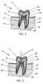
- FIG. 1is a cross-sectional elevation of a typical human tooth prior to undergoing the pulpectomy/root canal procedure of the present invention.
- FIG. 2is a cross-sectional elevation as in FIG. 1, showing the step of creating an opening through the top of the tooth to the pulp chamber within.
- FIG. 3is a cross-sectional elevation as in FIGS. 1 and 2, showing the cannula of the dental high velocity liquid jet tool being extended through the upper opening of the tooth and being actuated to emit a high pressure, high velocity jet.
- FIG. 4is a cross-sectional elevation as in FIGS. 1-3, showing the soft tissue within one root channel and a portion of the pulp chamber emulsified and undergoing aspiration.
- FIG. 5is a cross-sectional elevation as in FIGS. 1-4, showing the soft tissue within both root channels and all the pulp chamber emulsified and undergoing aspiration.
- FIG. 6is a cross-sectional elevation as in FIGS. 1-5, showing the pulp chamber and root channels packed with filler material and the upper opening filled at the completion of the procedure.
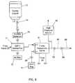
- FIG. 7is a schematic view of the pneumatic system of the present invention.
- FIG. 8is a schematic view of the hydraulic system of the present invention.
- FIG. 9is a plan view of a mechanical layout embodying the pneumatic and hydraulic systems of FIGS. 7 and 8.
- FIG. 10is an exploded view showing a handpiece and two interchangeable tip assemblies of the present invention.
- FIG. 11is an end view showing the quick connect coupling of the handpiece of the invention.
- FIG. 12is an exploded view showing the orifice mount and guide tube assembly of the invention.
- FIG. 13is an end view of the guide tube assembly shown in FIG. 12 .
- FIG. 14is a proximal end view of the orifice mount shown in FIG. 12 .
- FIG. 15is a perspective view of the orifice mount shown in FIG. 12 .
- FIG. 16is a side view showing the jet shroud assembled to the guide tube assembly of the invention.
- FIG. 17is a distal end view of the orifice mount shown in FIG. 12 .
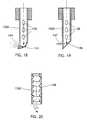
- FIGS. 18-20are cross-sectional side views of further embodiments of the guide tube of the invention.
- the present inventiongenerally comprises an apparatus and methods for dental treatments that overcome the problems associated with current mechanical and dental techniques and instruments.
- the inventioncomprises a technique for carrying out a pulpectomy or root canal: that is, removing the soft tissue within the tooth by excising, emulsifying and aspirating the soft tissue.
- a typical human tooth 10is comprised of a crown 11 extending above the gum tissue 12 , at least one root portion 13 received within a respective alveolus 14 , and a neck portion 16 joining the root and crown at the cemento-enamel junction.
- the alveoliare deep depressions in the bone tissue of the mandible 17 , and are lined with periosteum which is reflected on the tooth at the apex 18 of each root. At the margin of the alveolus the periosteum becomes continuous with the periodontal ligament of the gum tissue 12 .
- the hard tissue of the toothincludes the dentine 21 , which provides the primary structure of the tooth, and the very hard enamel layer 22 which forms a durable grinding surface and covers the crown 11 down to the cemento-enamel junction at the neck 16 .
- a pulp chamber 26Within the dentine layer 21 there is defined a pulp chamber 26 .
- Processes of the pulp chamber 26termed the root canal 27 , are disposed centrally in each root 13 and extend through the respective apex 18 at a minute orifice, the apical foramen 28 .
- the chamber 26 and canal(s) 27contain dental pulp, a soft, vascular tissue containing numerous nerves and blood vessels and other tissue components. The pulp provides enervation and sustenance to the tooth through the epithelial lining of the pulp chamber and canals.
- the method of the present inventionis used to treat a tooth that is diagnosed as diseased and requiring a pulpectomy/root canal procedure.
- the toothis initially opened by employing a dental drill 31 or equivalent burr or grinding tool.
- the resulting opening 32extends through the enamel and dentine to provide access to the pulp chamber 26 and root channels 27 , as shown in FIG. 3.
- a high velocity liquid jet dental tool 35is provided, including a handpiece 33 having a cannula 34 extending therefrom.
- the cannulaincludes a distal orifice adapted to generate a high velocity, high pressure, low volume jet 36 of liquid.
- the handpiecemaneuvered to insert the cannula 34 into the opening 32 to direct the jet 36 at the soft tissue within the chamber 26 and channels 27 .
- the jeteasily cuts through the soft tissue, and the energy and turbulence engendered by the jet causes the tissue to be emulsified upon contact. Moreover, the turbulent liquid easily penetrates into the narrow spaces of the root channels 27 (FIG. 4 ), effecting thorough excision and emulsification of the nerve and vascular tissue therein.
- the cannula 34may also provide vacuum aspiration to remove the emulsified tissue and jet fluid, or a second aspiration cannula may be employed.
- the pressure range of the high pressure jetis approximately 500-60,000 psi, and the jet diameter is approximately 10-800 microns. These parameters are selected to provide a liquid jet that is not capable of cutting nor detrimentally eroding the hard tissue of the tooth. As a result, the excision and emulsification action of the jet 36 cannot pass through the apical foramen 28 of the root, if the foramen is naturally closed, and thus cannot injure the alveolar sac or periosteum at the base of the root. Thus a source of substantial post-operative complications in prior art procedures is completely eliminated by the self-limiting feature of the invention.
- the jet 36acts quickly within the soft tissue, and the time necessary to excise, emulsify, and aspirate all the soft tissue within a typical tooth is approximately 10-240 seconds. Of course, more time is required for teeth such as molars having a plurality of root channels 27 . As shown in FIG. 5, the dental high velocity liquid jet tool 35 may be maneuvered to direct the cannula 34 and jet 36 into each of the root channels to remove all soft tissue therein.
- the liquid which constitutes the jet 36may comprise sterile water or medical grade saline solution, or an antiseptic solution, or an antibiotic solution, or an abrasive solution, or other medications or chemicals, or any combination thereof. Furthermore, more than one of these types of solutions may be used in serial order. For example, saline solution may be used for the excision and emulsification process, followed by an abrasive solution to scour the cavity, an antiseptic solution to eliminate indigenous bacteria and then an antibiotic solution to prevent regrowth of infective agents.
- the fluid jetmay comprise a pulsed jet formed by a pulse intensifier device in the handpiece of the dental high velocity liquid jet tool, as described in the US patent to Bair referenced above. Alternatively, the handpiece may be connected to a source of high pressure fluid to form a steady stream jet emanating from the orifice.
- the pulp chamber and root channelsAfter the pulp chamber and root channels have been fully aspirated and visualized for verification of removal, the pulp chamber and root channels are packed with an inert, aseptic material 41 , as is known in the dental art. Thereafter, the opening 32 is filled using a standard dental material 42 , such as silver amalgam, gold inlay or crown, cured composite material, or the like. The procedure is thus completed.
- a standard dental material 42such as silver amalgam, gold inlay or crown, cured composite material, or the like.
- a preferred embodiment of the apparatus for carryout out the procedure described abovemay include a pneumatic/hydraulic apparatus.
- the pneumatic portion 51 of the apparatusincludes an input connector 52 that is coupled to a pressurized air or gas source, such as a standard 150 psi supply typically available in a dental service installation.
- the input feedis limited by a 175 psi pressure relief valve 53 , and feeds a supply line 59 .
- a mechanical pressure regulator 54Connected to the supply line 59 is a mechanical pressure regulator 54 that is coupled to gauge 57 that may be visualized by the operator.
- the regulatorfeeds 50 psi pneumatic pressure to a pair of solenoid valves 58 A and 58 B.
- the valves 58feed operating pressure to respective ON and OFF sides of a three way hydraulic valve 81 in the hydraulic section of the apparatus, describe below and shown in FIG. 8.
- a 120 psi pressure switch 56is connected to the supply line to assure sufficient pressure to operate the pneumatic system.
- the supply line 59also feeds an electric pressure regulator 61 , which may have an adjustable range of 0-70 psi. which is monitored by a pressure transducer 62 .
- the regulator 61feeds a three way solenoid valve 63 , one output of which is fed to a pressure transducer 64 and hydraulic intensifier 71 (shown in FIG. 8 and described below), the other output being vented to atmosphere.
- the pneumatic systemalso includes an aspiration pump 66 which is coupled through a quick connect 67 to an aspiration hose 68 and thence to the operator's handpiece through tubing 137 , as shown in FIG. 12.
- a collection jar 69is connected between the quick connect and the pump 66 to capture aspirant (liquid, blood, tissue debris, etc.) from the operator's handpiece, as also detailed in the following description.
- the hydraulic system of the inventionincludes a pressure intensifier 71 that receives pneumatic operating pressure from valve 63 and exhausts into muffler 72 .
- the intensifier 71is connected to a liquid supply comprising a liquid reservoir such as a bag 73 of sterile water or the like that may be mixed with agents such as antibiotics, abrasives, antiseptics, and the like.
- the bag 73is connected to a standard irrigation connector 74 similar to an IV setup, and fed to a bubble detector 76 that halts operation of the system when flow is interrupted or the bag 73 is emptied.
- the output of intensifier 71which is a high pressure, sterile liquid stream, is fed to the normally open port of a three way pneumatic valve 81 .
- the valve 81is driven to open and close by pneumatic inputs from valves 58 , so that the relatively low pressure air supply may be used for on/off control of the relatively high pressure output of the intensifier 71 .
- the high pressure output of the valve 81is monitored by a high pressure transducer 82 and connected through a high pressure quick connect 83 to a high pressure supply hose 84 .
- a quick connect 86joins the hose 84 to the operator's handpiece 88 .
- the normally closed output of the valve 81is coupled through quick connect 89 to a vent bag 91 .
- transducers 62 and 64the outputs of the transducers 62 and 64 , pressure switch 56 , transducer 82 , and bubble detector 76 are all connected to a microprocessor (not shown) which is programmed to accept these inputs and control the performance of the combined systems and assure safe operation.
- FIG. 9there is shown a mechanical layout in which the major components are labeled with reference numerals ascribed above.
- the entire systemmay be embodied in a housing 90 that is sufficiently small (i.e., approximately 20 inches square) to be used in a typical dental service installation, or to be used as a portable instrument to service multiple dental treatment rooms.
- the high pressure liquid outputis conducted through pipe 91 to quick connect 83 , and thence through high pressure hose 84 to the handpiece 88 .
- a hook 92extends from the housing to support the vent bag 91 .
- a control input connector 93permits the system to be controlled by a foot switch, such foot switch arrangements being common in the dental arts.
- a bag 73is first connected through bubble detector 76 to the pressure intensifier 71 , and the apparatus is connected to electrical power and a pneumatic air supply.
- the aspiration pump 66is switched on to provide sufficient suction to clear the dental operation site of liquid and tissue debris.
- a handpieceis connected by quick connect 86 through high pressure tube 84 to the output of the valve 81 .
- the foot switchis used by the operator to actuate solenoid valves 58 A and 63 , thereby directing air pressure to the hydraulic intensifier 71 and to open the valve 81 .
- one embodiment of the handpiece 88includes a tubular barrel 101 having a central passage 102 extending axially therethrough.
- the proximal end of the barrel 101terminates in a rectangular projection 103 that is adapted to engage a quick connect fitting 86 .
- a recess 104 extending axially into the projection 103is adapted to receive a ultra-fine filter assembled to the quick connect fitting.
- a concave annular portion 106is provided with a high friction surface 107 to enhance grasping by the opposed finger and thumb of the user.
- a receptacle 108is formed in the distal end of the barrel 101 to receive a complementarily formed end 110 of interchangeable jet tube assemblies.
- jet tube assembly 109includes an angled distal end, and jet tube assembly 111 comprises a shorter, linear tubular shape.
- the ends 110are machined to form a 20 Kpsi metal-to-metal seal with the receptacle 108 , and to be secured therein by frictional engagement that is manually releasable.
- each jet tube assemblyincludes a jet forming arrangement.
- the distal end 116 of a jet tube assemblyis provided with a threaded socket 117 adapted to receive an orifice mount 118 .
- the mount 118is formed similarly to an elongated set screw, with fine external threads 119 to engage the socket 117 and a stepped flow passage 121 extending axially therethrough.
- an annular recess 122is formed to secure a disc-like orifice jewel 123 , which has a central orifice therethrough having a diameter in the range of 20-100 microns.
- the passage 124 of the jet tube assemblysupplies very high pressure liquid to the base of the orifice jewel, and a high velocity jet emanates from the orifice as a highly collimated beam that travels distally through the passage 121 along the axis thereof.
- a beveled proximal surface 126 of the orifice mount-is machined to high tolerances and polished to form an intimate seal with the inner end of the socket 117 and form a high pressure seal therewith.
- the distal end of the orifice mountis provided with a socket 127 adapted to receive a hex key to facilitate installation and adjustment.
- a guide tube assembly 131includes a housing 132 having an hexagonal outer conformation to permit engagement by a standard tool or wrench.
- the tubular interior cavity 133is threaded ( 134 ) from the proximal end to the medial portion thereof and adapted to engage the threads 119 of the orifice mount 118 .
- a guide tube 136extends distally and axially from the housing 132 , and provides a shielded pathway for the high velocity jet emanating from the jewel orifice 123 .
- An aspiration tube 137is coupled to the cavity 133 to apply suction thereto.
- a plurality of aspiration ports 138are provided in the guide tube 136 to apply suction and aspirate flowable materials from the site of the operation (the tissue target of the high velocity jet).
- further aspiration ports 139are formed in the distal end of the housing 132 to provide widespread aspiration that collects widespread sprayed material, and to prevent vacuum buildup if the ports 138 become blocked.
- the guide tube configurationmay vary in size, length, and diameter to accommodate various size teeth, different procedures, and other circumstances. All have one ore more aspiration ports to reduce liquid jet backup pressure and remove fluid build up.
- the housing 132may be adjustably positioned on the orifice mount, whereby the distance from the orifice jewel to the tissue target may be selected, with the housing 132 and the guide tube 136 acting as a standoff. Due to the fact that the jet beam force decreases with the square of the distance traveled from the orifice, the selective positioning of the housing 132 enables the user to control the impact force of the jet beam and thus control the effect on tissue.
- a smooth cylindrical neck portion 141 of the housing 132is provided to support a shroud 142 .
- the shroud 142comprises a curved concave member having a central opening that is received about the neck 141 , the shroud extending about the guide tube 136 to confine spray from the impact site of the jet.
- the shroudmay be formed of transparent plastic or polymer material to permit visualization of the operation site. Note that the aspiration ports 138 and 139 are all functioning within the confines of the shroud to remove aspirant as it is confined and collected.
- a variant of the guide tube 136 Aincludes a distal end 143 that is closed, curved, and angled obliquely.
- An outlet port 144is placed in the side wall of the guide tube.
- the high velocity coherent jet beamimpacts on the end wall 143 and forms a high velocity spray, which is directed through the port 144 .
- the high velocity sprayis useful for procedures other than cutting and emulsification, such as superficial cleaning and the like.
- a variant of the guide tube 136 Bincludes a distal end 146 that is closed, planar, and angled obliquely.
- An outlet port 147is placed in the side wall of the guide tube.
- the high velocity coherent jet beamimpacts on the end wall 146 and forms a high velocity spray, which is directed through the port 147 .
- the guide tubemay be rotatably mounted in the housing 132 to permit the port 144 or 147 to be directed at any angle about the axis of the assembly, thereby providing greater utility in the narrow confines of oral operations.
- a variant of the guide tube 136 Cincludes a distal opening aligned with the axis of the tube, and the interior bore of the tube is provided with a helical surface, similar to a rifling surface, that influences the passing jet beam to impart a turbulent, swirling effect thereto. This effect broadens the impact zone of the jet and reduces the cutting action, while augmenting other aspects of the jet effect, such as abrasion and emulsification.
- the high velocity liquid jet dental instrument disclosed hereinmay be employed to carry out other treatments and procedures in addition to root canal and pulpectomy.
- the fluid jetis exceptionally well suited to carry out removal of calculus and plaque, and for root planing. This process may be enhanced through the use of an abrasive solution as the fluid for the fluid jet.
- the fluid jetmay be used for excision and resection of the gingiva, removal of granulated tissue, as well as muco-osseous surgery.
- the fluid jetmay also be an adjunct to tooth extraction, in that the jet ay be used to sever the fibrous attachments to the tooth root, thereby easing the subsequent extraction. These procedures may be aided by the use of antibiotic solutions to form the fluid jet.
- a fluid jet of sufficient energymay be used to remove various dental tissue, thereby providing simple caries removal and preparation for filling. It has been found that proper choice of jet energy selectively removes the various tissue while the health surrounding enamel and dentine may remain unscathed by the jet. This process may be enhanced through the use of an abrasive solution as the fluid for the fluid jet.
- the high velocity liquid jet dental instrumentprovides all of these treatment options, as well as the root canal/pulpectomy procedure, while creating virtually no heat or vibration at the target site. This characteristic is a notable advance over prior art mechanical tools, ultrasound instruments, and dental lasers.
Landscapes
- Health & Medical Sciences (AREA)
- General Health & Medical Sciences (AREA)
- Veterinary Medicine (AREA)
- Public Health (AREA)
- Dentistry (AREA)
- Epidemiology (AREA)
- Life Sciences & Earth Sciences (AREA)
- Animal Behavior & Ethology (AREA)
- Oral & Maxillofacial Surgery (AREA)
- Engineering & Computer Science (AREA)
- Water Supply & Treatment (AREA)
- Biomedical Technology (AREA)
- Neurology (AREA)
- Neurosurgery (AREA)
- Nuclear Medicine, Radiotherapy & Molecular Imaging (AREA)
- Surgery (AREA)
- Dental Tools And Instruments Or Auxiliary Dental Instruments (AREA)
Abstract
Description
Claims (28)
Priority Applications (1)
| Application Number | Priority Date | Filing Date | Title |
|---|---|---|---|
| US09/844,967US6497572B2 (en) | 1997-07-09 | 2001-04-27 | Apparatus for dental treatment using high pressure liquid jet |
Applications Claiming Priority (2)
| Application Number | Priority Date | Filing Date | Title |
|---|---|---|---|
| US08/890,496US6224378B1 (en) | 1997-07-09 | 1997-07-09 | Method and apparatus for dental treatment using high pressure liquid jet |
| US09/844,967US6497572B2 (en) | 1997-07-09 | 2001-04-27 | Apparatus for dental treatment using high pressure liquid jet |
Related Parent Applications (1)
| Application Number | Title | Priority Date | Filing Date |
|---|---|---|---|
| US08/890,496Continuation-In-PartUS6224378B1 (en) | 1997-07-09 | 1997-07-09 | Method and apparatus for dental treatment using high pressure liquid jet |
Publications (2)
| Publication Number | Publication Date |
|---|---|
| US20010055742A1 US20010055742A1 (en) | 2001-12-27 |
| US6497572B2true US6497572B2 (en) | 2002-12-24 |
Family
ID=46257714
Family Applications (1)
| Application Number | Title | Priority Date | Filing Date |
|---|---|---|---|
| US09/844,967Expired - LifetimeUS6497572B2 (en) | 1997-07-09 | 2001-04-27 | Apparatus for dental treatment using high pressure liquid jet |
Country Status (1)
| Country | Link |
|---|---|
| US (1) | US6497572B2 (en) |
Cited By (102)
| Publication number | Priority date | Publication date | Assignee | Title |
|---|---|---|---|---|
| US6676629B2 (en) | 1995-02-06 | 2004-01-13 | Mark S. Andrew | Tissue liquefaction and aspiration for dental treatment |
| US20040030326A1 (en)* | 2002-04-09 | 2004-02-12 | Altshuler Gregory B. | Method and apparatus for processing hard material |
| US20040202980A1 (en)* | 2003-04-14 | 2004-10-14 | Policicchio Piero A. | Dental prophylaxis and air appliance |
| WO2005065032A2 (en) | 2004-01-08 | 2005-07-21 | Tavtech Ltd. | A high velocity liquid-gas mist tissue abrasion device |
| US7011644B1 (en) | 1995-02-06 | 2006-03-14 | Andrew Mark S | Tissue liquefaction and aspiration for dental treatment |
| US20070248932A1 (en)* | 2006-04-20 | 2007-10-25 | Morteza Gharib | Apparatus and methods for treating root canals of teeth |
| US20070287125A1 (en)* | 2004-06-11 | 2007-12-13 | David Weill | Simplified Cleaning And Filling Device |
| US20080003536A1 (en)* | 2002-04-09 | 2008-01-03 | Altshuler Gregory B | Method and apparatus for processing hard material |
| USD565175S1 (en) | 2006-02-24 | 2008-03-25 | Water Pik, Inc. | Water jet base |
| USD574952S1 (en) | 2006-02-24 | 2008-08-12 | Water Pik, Inc. | Water jet handle |
| US20090101028A1 (en)* | 2007-10-18 | 2009-04-23 | Renzo Melotti | Doctor blade assembly |
| WO2009137815A1 (en) | 2008-05-09 | 2009-11-12 | Dentatek Corporation | Apparatus and methods for root canal treatments |
| US7670141B2 (en) | 2006-07-07 | 2010-03-02 | Water Pik, Inc. | Oral irrigator |
| US20100143861A1 (en)* | 2007-01-25 | 2010-06-10 | Dentatek Corporation | Apparatus and methods for monitoring a tooth |
| USD629884S1 (en) | 2009-12-16 | 2010-12-28 | Water Pik, Inc. | Powered irrigator for sinus cavity rinse |
| WO2011060327A1 (en) | 2009-11-13 | 2011-05-19 | Dentatek Corporation | Liquid jet apparatus and methods for dental treatments |
| US20110150680A1 (en)* | 2009-12-22 | 2011-06-23 | Smith & Nephew, Inc. | Disposable Pumping System and Coupler |
| US20110223555A1 (en)* | 2008-10-07 | 2011-09-15 | Michael Thoms | Jet device |
| US8113832B2 (en) | 2002-12-31 | 2012-02-14 | Water Pik, Inc. | Hand held oral irrigator |
| US20120165724A1 (en)* | 2010-12-22 | 2012-06-28 | Jack Robert Auld | Hydraulic vitrectomy probe |
| US20120237893A1 (en)* | 2010-10-21 | 2012-09-20 | Sonendo, Inc. | Apparatus, methods, and compositions for endodontic treatments |
| USD670373S1 (en) | 2010-12-16 | 2012-11-06 | Water Pik, Inc. | Powered irrigator for sinus cavity rinse |
| US8408483B2 (en) | 2006-02-24 | 2013-04-02 | Water Pik, Inc. | Adjustable flow regulator for dental water jet |
| US20140099597A1 (en)* | 2012-04-13 | 2014-04-10 | Sonendo Inc. | Apparatus and methods for cleaning teeth and gingival pockets |
| USD707350S1 (en) | 2012-10-11 | 2014-06-17 | Water Pik, Inc. | Handheld water flosser |
| US8801667B2 (en) | 2009-12-16 | 2014-08-12 | Water Pik, Inc. | Pump for powered irrigator for sinus cavity rinse |
| USD714929S1 (en) | 2013-03-14 | 2014-10-07 | Water Pik, Inc. | Base for water flosser |
| USD714930S1 (en) | 2013-03-14 | 2014-10-07 | Water Pik, Inc. | Reservoir for water flosser |
| USD717427S1 (en) | 2013-03-14 | 2014-11-11 | Water Pik, Inc. | Handle for water flosser |
| USD725770S1 (en) | 2013-03-14 | 2015-03-31 | Water Pik, Inc. | Reservoir for water flosser |
| US20150173852A1 (en)* | 2013-05-01 | 2015-06-25 | Sonendo, Inc. | Apparatus and methods for treating teeth |
| US9084651B2 (en) | 2012-09-17 | 2015-07-21 | Zohar Laufer | Dental micro-tornado tissue cutting and removal method and apparatus |
| USD745966S1 (en) | 2013-04-15 | 2015-12-22 | Sonendo, Inc. | Dental handpiece |
| USD756122S1 (en) | 2009-01-28 | 2016-05-17 | Water Pik, Inc. | Oral irrigator tip |
| USD772397S1 (en) | 2014-12-01 | 2016-11-22 | Water Pik, Inc. | Oral irrigator with a charging device |
| USD772396S1 (en) | 2014-12-01 | 2016-11-22 | Water Pik, Inc. | Handheld oral irrigator |
| US9504536B2 (en) | 2013-02-04 | 2016-11-29 | Sonendo, Inc. | Dental treatment system |
| USD780908S1 (en) | 2015-11-03 | 2017-03-07 | Water Pik, Inc. | Handheld oral irrigator |
| USD782657S1 (en) | 2016-03-02 | 2017-03-28 | Water Pik, Inc. | Oral irrigator handle |
| USD782656S1 (en) | 2016-01-25 | 2017-03-28 | Water Pik, Inc. | Oral irrigator |
| USD783810S1 (en) | 2016-02-22 | 2017-04-11 | Water Pik, Inc. | Handle for an oral irrigator |
| USD783809S1 (en) | 2016-01-25 | 2017-04-11 | Water Pik, Inc. | Oral irrigator handle |
| USD786422S1 (en) | 2016-01-25 | 2017-05-09 | Water Pik, Inc. | Oral irrigator |
| USD788907S1 (en) | 2013-03-14 | 2017-06-06 | Water Pik, Inc. | Water flosser base unit with reservoir lid |
| US9713511B2 (en) | 2012-04-15 | 2017-07-25 | Fluidfile Ltd. | Apparatus and method for endodontic treatment |
| USD794773S1 (en) | 2016-07-19 | 2017-08-15 | Water Pik, Inc. | Oral irrigator |
| US9743999B2 (en) | 2014-08-29 | 2017-08-29 | Piero A. Policicchio | Dental prophylaxis device and air appliance |
| USD796028S1 (en) | 2016-07-19 | 2017-08-29 | Water Pik, Inc. | Oral irrigator |
| US20170258552A1 (en)* | 2014-11-25 | 2017-09-14 | Ghassan YARED | Dental irrigation, cleaning and debridement system, device and instrument |
| USD802119S1 (en) | 2016-03-02 | 2017-11-07 | Water Pik, Inc. | Oral irrigator |
| USD802120S1 (en) | 2007-02-27 | 2017-11-07 | Water Pik, Inc. | Tip for oral irrigator |
| USD802747S1 (en) | 2016-07-19 | 2017-11-14 | Water Pik, Inc. | Reservoir for oral irrigator |
| USD804016S1 (en) | 2016-02-05 | 2017-11-28 | Water Pik, Inc. | Handheld oral irrigator |
| USD804018S1 (en) | 2016-07-19 | 2017-11-28 | Water Pik, Inc. | Base for an oral irrigator |
| USD807822S1 (en) | 2016-07-19 | 2018-01-16 | Water Pik, Inc. | Power supply cartridge |
| US9877801B2 (en) | 2013-06-26 | 2018-01-30 | Sonendo, Inc. | Apparatus and methods for filling teeth and root canals |
| USD809651S1 (en) | 2016-07-19 | 2018-02-06 | Water Pik, Inc. | Combination base and reservoir for an oral irrigator |
| USD809650S1 (en) | 2016-02-22 | 2018-02-06 | Water Pik, Inc. | Oral irrigator |
| US9980793B2 (en) | 2013-11-27 | 2018-05-29 | Water Pik, Inc. | Oral hygiene system |
| USD819956S1 (en) | 2016-01-25 | 2018-06-12 | Water Pik, Inc. | Kit bag |
| USD822196S1 (en) | 2016-01-14 | 2018-07-03 | Water Pik, Inc. | Oral irrigator |
| US10016254B2 (en) | 2013-12-20 | 2018-07-10 | Water Pik, Inc. | Dental water jet |
| USD822826S1 (en) | 2016-12-15 | 2018-07-10 | Water Pik, Inc. | Oral irrigator base |
| USD822825S1 (en) | 2016-12-15 | 2018-07-10 | Water Pik, Inc. | Oral irrigator unit |
| US10022207B2 (en) | 2013-11-27 | 2018-07-17 | Water Pik, Inc. | Oral irrigator with slide pause switch |
| USD825741S1 (en) | 2016-12-15 | 2018-08-14 | Water Pik, Inc. | Oral irrigator handle |
| USD829886S1 (en) | 2016-12-15 | 2018-10-02 | Water Pik, Inc. | Oral irrigator base |
| USD829887S1 (en) | 2017-02-06 | 2018-10-02 | Water Pik, Inc. | Oral irrigator reservoir |
| US10105201B2 (en) | 2012-10-11 | 2018-10-23 | Water Pik, Inc. | Interdental cleaner using water supply |
| USD832418S1 (en) | 2016-12-15 | 2018-10-30 | Water Pik, Inc. | Oral irrigator base |
| USD832420S1 (en) | 2016-12-15 | 2018-10-30 | Water Pik, Inc. | Oral irrigator base |
| USD832419S1 (en) | 2016-12-15 | 2018-10-30 | Water Pik, Inc. | Oral irrigator unit |
| USD833000S1 (en) | 2016-12-15 | 2018-11-06 | Water Pik, Inc. | Oral irrigator unit |
| USD833602S1 (en) | 2017-02-06 | 2018-11-13 | Water Pik, Inc. | Oral irrigator base |
| USD833601S1 (en) | 2017-02-06 | 2018-11-13 | Water Pik, Inc. | Oral irrigator |
| USD833600S1 (en) | 2016-12-15 | 2018-11-13 | Water Pik, Inc. | Oral irrigator reservoir |
| USD834180S1 (en) | 2016-12-15 | 2018-11-20 | Water Pik, Inc. | Oral irrigator base |
| USD839409S1 (en) | 2016-12-15 | 2019-01-29 | Water Pik, Inc. | Oral irrigator unit |
| USD840023S1 (en) | 2016-12-15 | 2019-02-05 | Water Pik, Inc. | Oral irrigator reservoir |
| USD840022S1 (en) | 2016-12-15 | 2019-02-05 | Water Pik, Inc. | Oral irrigator handle |
| US10258442B2 (en) | 2009-03-20 | 2019-04-16 | Water Pik, Inc. | Oral irrigator appliance with radiant energy delivery for bactericidal effect |
| US10363120B2 (en) | 2012-12-20 | 2019-07-30 | Sonendo, Inc. | Apparatus and methods for cleaning teeth and root canals |
| US20190262109A1 (en)* | 2006-04-20 | 2019-08-29 | Sonendo, Inc. | Apparatus and methods for treating root canals of teeth |
| USD867579S1 (en) | 2016-12-15 | 2019-11-19 | Water Pik, Inc. | Oral irrigator unit |
| USD868243S1 (en) | 2018-03-16 | 2019-11-26 | Water Pik, Inc. | Oral irrigator tip |
| USD877324S1 (en) | 2018-05-17 | 2020-03-03 | Water Pik, Inc. | Oral irrigator handle |
| USD888936S1 (en) | 2019-02-22 | 2020-06-30 | Water Pik, Inc. | Cordless water flosser |
| USD889636S1 (en) | 2019-02-22 | 2020-07-07 | Water Pik, Inc. | Water flosser |
| US10779922B2 (en) | 2016-12-15 | 2020-09-22 | Water Pik, Inc. | Pause valve and swivel assemblies for oral irrigator handle |
| US10806544B2 (en) | 2016-04-04 | 2020-10-20 | Sonendo, Inc. | Systems and methods for removing foreign objects from root canals |
| US10835356B2 (en) | 2016-01-25 | 2020-11-17 | Water Pik, Inc. | Swivel assembly for oral irrigator handle |
| US10993867B2 (en) | 2016-03-02 | 2021-05-04 | Water Pik, Inc. | Actuation assembly for an oral irrigator |
| US11173019B2 (en) | 2012-03-22 | 2021-11-16 | Sonendo, Inc. | Apparatus and methods for cleaning teeth |
| US11213376B2 (en) | 2016-01-25 | 2022-01-04 | Water Pik, Inc. | Reduced form factor oral irrigator |
| US11213375B2 (en) | 2012-12-20 | 2022-01-04 | Sonendo, Inc. | Apparatus and methods for cleaning teeth and root canals |
| US11350993B2 (en) | 2006-08-24 | 2022-06-07 | Pipstek, Llc | Dental and medical treatments and procedures |
| US11389279B2 (en) | 2016-12-15 | 2022-07-19 | Water Pik, Inc. | Oral irrigator with magnetic attachment |
| USD966498S1 (en) | 2020-09-15 | 2022-10-11 | Water Pik, Inc. | Oral irrigator |
| USD997355S1 (en) | 2020-10-07 | 2023-08-29 | Sonendo, Inc. | Dental treatment instrument |
| US11826214B2 (en) | 2014-12-01 | 2023-11-28 | Water Pik, Inc. | Oral irrigator |
| USD1016274S1 (en) | 2021-02-16 | 2024-02-27 | Water Pik, Inc. | Oral irrigator |
| US12114924B2 (en) | 2006-08-24 | 2024-10-15 | Pipstek, Llc | Treatment system and method |
Families Citing this family (3)
| Publication number | Priority date | Publication date | Assignee | Title |
|---|---|---|---|---|
| USD530010S1 (en) | 2004-03-17 | 2006-10-10 | Water Pik, Inc. | Base for an oral implement |
| US20140342318A1 (en)* | 2013-05-16 | 2014-11-20 | Pranadent LLC | Device and Method for Treating Oral Pigmentation |
| WO2015059707A1 (en)* | 2013-10-23 | 2015-04-30 | Fluidfile Ltd. | Apparatus and method for endodontic treatment |
Citations (4)
| Publication number | Priority date | Publication date | Assignee | Title |
|---|---|---|---|---|
| US3561433A (en)* | 1968-07-22 | 1971-02-09 | Leslie J Kovach | Dental cleaning and massaging device |
| US3703170A (en)* | 1971-03-04 | 1972-11-21 | Gen Electric | Oral hygiene apparatus |
| US5620414A (en)* | 1992-06-30 | 1997-04-15 | Campbell, Jr.; Robert M. | Apparatus and method for effecting surgical incision through use of a fluid jet |
| US6159006A (en)* | 1999-01-06 | 2000-12-12 | Conair Corporation | Portable oral irrigator |
- 2001
- 2001-04-27USUS09/844,967patent/US6497572B2/ennot_activeExpired - Lifetime
Patent Citations (4)
| Publication number | Priority date | Publication date | Assignee | Title |
|---|---|---|---|---|
| US3561433A (en)* | 1968-07-22 | 1971-02-09 | Leslie J Kovach | Dental cleaning and massaging device |
| US3703170A (en)* | 1971-03-04 | 1972-11-21 | Gen Electric | Oral hygiene apparatus |
| US5620414A (en)* | 1992-06-30 | 1997-04-15 | Campbell, Jr.; Robert M. | Apparatus and method for effecting surgical incision through use of a fluid jet |
| US6159006A (en)* | 1999-01-06 | 2000-12-12 | Conair Corporation | Portable oral irrigator |
Cited By (213)
| Publication number | Priority date | Publication date | Assignee | Title |
|---|---|---|---|---|
| US6676629B2 (en) | 1995-02-06 | 2004-01-13 | Mark S. Andrew | Tissue liquefaction and aspiration for dental treatment |
| USRE43617E1 (en) | 1995-02-06 | 2012-08-28 | Andrew Mark S | Tissue liquefaction and aspiration |
| US7011644B1 (en) | 1995-02-06 | 2006-03-14 | Andrew Mark S | Tissue liquefaction and aspiration for dental treatment |
| US20040030326A1 (en)* | 2002-04-09 | 2004-02-12 | Altshuler Gregory B. | Method and apparatus for processing hard material |
| US8348933B2 (en) | 2002-04-09 | 2013-01-08 | Laser Abrasive Technologies, Llc | Method and apparatus for processing hard material |
| US7267672B2 (en)* | 2002-04-09 | 2007-09-11 | Gregory B. Altshuler | Method and apparatus for processing hard material |
| US20080021441A1 (en)* | 2002-04-09 | 2008-01-24 | Altshuler Gregory B | Method and apparatus for processing hard material |
| US20080003536A1 (en)* | 2002-04-09 | 2008-01-03 | Altshuler Gregory B | Method and apparatus for processing hard material |
| US8113832B2 (en) | 2002-12-31 | 2012-02-14 | Water Pik, Inc. | Hand held oral irrigator |
| US9980794B2 (en) | 2002-12-31 | 2018-05-29 | Water Pik, Inc. | Irrigating device with variable pressure pulse |
| US10617500B2 (en) | 2002-12-31 | 2020-04-14 | Water Pik, Inc. | Oral irrigator |
| US20040202980A1 (en)* | 2003-04-14 | 2004-10-14 | Policicchio Piero A. | Dental prophylaxis and air appliance |
| WO2005065032A2 (en) | 2004-01-08 | 2005-07-21 | Tavtech Ltd. | A high velocity liquid-gas mist tissue abrasion device |
| US7901373B2 (en) | 2004-01-08 | 2011-03-08 | Tavtech Ltd. | High velocity liquid-gas mist tissue abrasion device |
| US20080319453A1 (en)* | 2004-01-08 | 2008-12-25 | Michael Tavger | High Velocity Liquid-Gas Mist Tissue Abrasion Device |
| US8317514B2 (en)* | 2004-06-11 | 2012-11-27 | David Weill | Simplified cleaning and filling device |
| US20070287125A1 (en)* | 2004-06-11 | 2007-12-13 | David Weill | Simplified Cleaning And Filling Device |
| US11872097B2 (en) | 2006-02-24 | 2024-01-16 | Water Pik, Inc. | Dental water jet with storage container reservoir cover |
| US8408483B2 (en) | 2006-02-24 | 2013-04-02 | Water Pik, Inc. | Adjustable flow regulator for dental water jet |
| USD574952S1 (en) | 2006-02-24 | 2008-08-12 | Water Pik, Inc. | Water jet handle |
| US11197745B2 (en) | 2006-02-24 | 2021-12-14 | Water Pik, Inc. | Removable fluid connection fitting for oral irrigator |
| US8641649B2 (en) | 2006-02-24 | 2014-02-04 | Water Pik, Inc. | Pump for dental water jet |
| USD565175S1 (en) | 2006-02-24 | 2008-03-25 | Water Pik, Inc. | Water jet base |
| US8888727B2 (en) | 2006-02-24 | 2014-11-18 | Water Pik, Inc. | Vibration damping for dental water jet |
| US10010389B2 (en) | 2006-02-24 | 2018-07-03 | Water Pik, Inc. | Dental water jet device |
| US9050157B2 (en) | 2006-02-24 | 2015-06-09 | Water Pik, Inc. | Dental water jet with storage container reservoir cover |
| US8808209B2 (en) | 2006-02-24 | 2014-08-19 | Water Pik, Inc. | Dental water jet irrigator handle |
| US11432916B2 (en) | 2006-02-24 | 2022-09-06 | Water Pik, Inc. | Oral irrigator with handle support |
| US10016263B2 (en)* | 2006-04-20 | 2018-07-10 | Sonendo, Inc. | Apparatus and methods for treating root canals of teeth |
| US10010388B2 (en)* | 2006-04-20 | 2018-07-03 | Sonendo, Inc. | Apparatus and methods for treating root canals of teeth |
| EP2015698A4 (en)* | 2006-04-20 | 2011-10-26 | Sonendo Inc | APPARATUS AND METHODS FOR TREATING RADICULAR CHANNELS OF TEETH |
| EP3311770A1 (en) | 2006-04-20 | 2018-04-25 | Sonendo, Inc. | Apparatus and methods for treating root canals of teeth |
| US10039625B2 (en)* | 2006-04-20 | 2018-08-07 | Sonendo, Inc. | Apparatus and methods for treating root canals of teeth |
| US20230028923A1 (en)* | 2006-04-20 | 2023-01-26 | Sonendo, Inc. | Apparatus and methods for treating root canals of teeth |
| US10835355B2 (en)* | 2006-04-20 | 2020-11-17 | Sonendo, Inc. | Apparatus and methods for treating root canals of teeth |
| US20200069402A1 (en)* | 2006-04-20 | 2020-03-05 | Sonendo, Inc. | Apparatus and methods for treating root canals of teeth |
| US20190262109A1 (en)* | 2006-04-20 | 2019-08-29 | Sonendo, Inc. | Apparatus and methods for treating root canals of teeth |
| EP4272694A2 (en) | 2006-04-20 | 2023-11-08 | Sonendo, Inc. | Apparatus for treating root canals of teeth |
| US10617498B2 (en)* | 2006-04-20 | 2020-04-14 | Sonendo, Inc. | Apparatus and methods for treating root canals of teeth |
| AU2007240780B2 (en)* | 2006-04-20 | 2014-01-16 | Sonendo, Inc. | Apparatus and methods for treating root canals of teeth |
| WO2007124038A3 (en)* | 2006-04-20 | 2008-07-03 | Dentatek Corp | Apparatus and methods for treating root canals of teeth |
| US11918432B2 (en) | 2006-04-20 | 2024-03-05 | Sonendo, Inc. | Apparatus and methods for treating root canals of teeth |
| US20150366634A1 (en)* | 2006-04-20 | 2015-12-24 | Sonendo, Inc. | Apparatus and methods for treating root canals of teeth |
| US8753121B2 (en)* | 2006-04-20 | 2014-06-17 | Sonendo, Inc. | Apparatus and methods for treating root canals of teeth |
| WO2007124038A2 (en) | 2006-04-20 | 2007-11-01 | Dentatek Corporation | Apparatus and methods for treating root canals of teeth |
| US20150132712A1 (en)* | 2006-04-20 | 2015-05-14 | Sonendo, Inc. | Apparatus and methods for treating root canals of teeth |
| US20070248932A1 (en)* | 2006-04-20 | 2007-10-25 | Morteza Gharib | Apparatus and methods for treating root canals of teeth |
| US8403665B2 (en) | 2006-07-07 | 2013-03-26 | Water Pik, Inc. | Oral irrigator |
| USD747464S1 (en) | 2006-07-07 | 2016-01-12 | Water Pik, Inc. | Handheld oral irrigator |
| US7670141B2 (en) | 2006-07-07 | 2010-03-02 | Water Pik, Inc. | Oral irrigator |
| US9775692B2 (en) | 2006-07-07 | 2017-10-03 | Water Pik, Inc. | Oral irrigator with variable pressure |
| US11684421B2 (en) | 2006-08-24 | 2023-06-27 | Pipstek, Llc | Dental and medical treatments and procedures |
| US12213731B2 (en) | 2006-08-24 | 2025-02-04 | Pipstek, Llc | Dental and medical treatments and procedures |
| US12114924B2 (en) | 2006-08-24 | 2024-10-15 | Pipstek, Llc | Treatment system and method |
| US11350993B2 (en) | 2006-08-24 | 2022-06-07 | Pipstek, Llc | Dental and medical treatments and procedures |
| US11426239B2 (en) | 2006-08-24 | 2022-08-30 | Pipstek, Llc | Dental and medical treatments and procedures |
| EP2821027A2 (en) | 2007-01-25 | 2015-01-07 | Sonendo, Inc. | Apparatus for removing organic material from a root canal of a tooth |
| US20100143861A1 (en)* | 2007-01-25 | 2010-06-10 | Dentatek Corporation | Apparatus and methods for monitoring a tooth |
| USD802120S1 (en) | 2007-02-27 | 2017-11-07 | Water Pik, Inc. | Tip for oral irrigator |
| USD867580S1 (en) | 2007-02-27 | 2019-11-19 | Water Pik, Inc. | Oral irrigator tip with bristles |
| US20090101028A1 (en)* | 2007-10-18 | 2009-04-23 | Renzo Melotti | Doctor blade assembly |
| US20110111365A1 (en)* | 2008-05-09 | 2011-05-12 | Dentatek Corporation | Apparatus and methods for root canal treatments |
| WO2009137815A1 (en) | 2008-05-09 | 2009-11-12 | Dentatek Corporation | Apparatus and methods for root canal treatments |
| US20110223555A1 (en)* | 2008-10-07 | 2011-09-15 | Michael Thoms | Jet device |
| USD756122S1 (en) | 2009-01-28 | 2016-05-17 | Water Pik, Inc. | Oral irrigator tip |
| US10258442B2 (en) | 2009-03-20 | 2019-04-16 | Water Pik, Inc. | Oral irrigator appliance with radiant energy delivery for bactericidal effect |
| US11173020B2 (en) | 2009-03-20 | 2021-11-16 | Water Pik, Inc. | Oral irrigator appliance with radiant energy delivery for bactericidal effect |
| US20170273758A1 (en)* | 2009-11-13 | 2017-09-28 | Sonendo, Inc. | Liquid jet apparatus and methods for dental treatments |
| EP3384870A1 (en) | 2009-11-13 | 2018-10-10 | Sonendo, Inc. | Liquid jet apparatus for dental treatments |
| US9492244B2 (en) | 2009-11-13 | 2016-11-15 | Sonendo, Inc. | Liquid jet apparatus and methods for dental treatments |
| CN102724929A (en)* | 2009-11-13 | 2012-10-10 | 索南多股份有限公司 | Liquid jet apparatus and methods for dental treatments |
| CN102724929B (en)* | 2009-11-13 | 2016-04-13 | 索南多股份有限公司 | For liquid jet equipment and the method for dental treatment |
| US20220296346A1 (en)* | 2009-11-13 | 2022-09-22 | Sonendo, Inc. | Liquid jet apparatus and methods for dental treatments |
| EP3878398A2 (en) | 2009-11-13 | 2021-09-15 | Sonendo, Inc. | Dental treatment apparatus |
| US11160645B2 (en)* | 2009-11-13 | 2021-11-02 | Sonendo, Inc. | Liquid jet apparatus and methods for dental treatments |
| WO2011060327A1 (en) | 2009-11-13 | 2011-05-19 | Dentatek Corporation | Liquid jet apparatus and methods for dental treatments |
| US12268565B2 (en)* | 2009-11-13 | 2025-04-08 | Sonendo, Inc. | Liquid jet apparatus and methods for dental treatments |
| US10420630B2 (en)* | 2009-11-13 | 2019-09-24 | Sonendo, Inc. | Liquid jet apparatus and methods for dental treatments |
| US9061096B2 (en) | 2009-12-16 | 2015-06-23 | Water Pik, Inc. | Powered irrigator for sinus cavity rinse |
| US8808245B2 (en) | 2009-12-16 | 2014-08-19 | Water Pik, Inc. | Powered irrigator for sinus cavity rinse with detachable reservoir |
| USD629884S1 (en) | 2009-12-16 | 2010-12-28 | Water Pik, Inc. | Powered irrigator for sinus cavity rinse |
| US8801667B2 (en) | 2009-12-16 | 2014-08-12 | Water Pik, Inc. | Pump for powered irrigator for sinus cavity rinse |
| US8932269B2 (en) | 2009-12-22 | 2015-01-13 | Smith & Nephew, Inc. | Disposable pumping system and coupler |
| US9341184B2 (en) | 2009-12-22 | 2016-05-17 | Smith & Nephew, Inc. | Disposable pumping system and coupler |
| US20110150680A1 (en)* | 2009-12-22 | 2011-06-23 | Smith & Nephew, Inc. | Disposable Pumping System and Coupler |
| US8337175B2 (en) | 2009-12-22 | 2012-12-25 | Smith & Nephew, Inc. | Disposable pumping system and coupler |
| EP3808306A1 (en) | 2010-10-21 | 2021-04-21 | Sonendo, Inc. | Apparatus for endodontic treatments |
| EP4368142A2 (en) | 2010-10-21 | 2024-05-15 | Sonendo, Inc. | Apparatus for endodontic treatments |
| US10702355B2 (en) | 2010-10-21 | 2020-07-07 | Sonendo, Inc. | Apparatus, methods, and compositions for endodontic treatments |
| US10806543B2 (en) | 2010-10-21 | 2020-10-20 | Sonendo, Inc. | Apparatus, methods, and compositions for endodontic treatments |
| US20120237893A1 (en)* | 2010-10-21 | 2012-09-20 | Sonendo, Inc. | Apparatus, methods, and compositions for endodontic treatments |
| US9675426B2 (en)* | 2010-10-21 | 2017-06-13 | Sonendo, Inc. | Apparatus, methods, and compositions for endodontic treatments |
| US12186151B2 (en) | 2010-10-21 | 2025-01-07 | Sonendo, Inc. | Apparatus, methods, and compositions for endodontic treatments |
| USD670373S1 (en) | 2010-12-16 | 2012-11-06 | Water Pik, Inc. | Powered irrigator for sinus cavity rinse |
| USD694398S1 (en) | 2010-12-16 | 2013-11-26 | Water Pik, Inc. | Powered irrigator for sinus cavity rinse |
| US8540743B2 (en)* | 2010-12-22 | 2013-09-24 | Alcon Research, Ltd. | Hydraulic vitrectomy probe |
| US20120165724A1 (en)* | 2010-12-22 | 2012-06-28 | Jack Robert Auld | Hydraulic vitrectomy probe |
| US11173019B2 (en) | 2012-03-22 | 2021-11-16 | Sonendo, Inc. | Apparatus and methods for cleaning teeth |
| EP4403132A2 (en) | 2012-03-22 | 2024-07-24 | Sonendo, Inc. | Apparatus for cleaning teeth |
| US20140099597A1 (en)* | 2012-04-13 | 2014-04-10 | Sonendo Inc. | Apparatus and methods for cleaning teeth and gingival pockets |
| US10631962B2 (en)* | 2012-04-13 | 2020-04-28 | Sonendo, Inc. | Apparatus and methods for cleaning teeth and gingival pockets |
| US10098717B2 (en) | 2012-04-13 | 2018-10-16 | Sonendo, Inc. | Apparatus and methods for cleaning teeth and gingival pockets |
| US11284978B2 (en) | 2012-04-13 | 2022-03-29 | Sonendo, Inc. | Apparatus and methods for cleaning teeth and gingival pockets |
| US10327866B2 (en) | 2012-04-15 | 2019-06-25 | Fluidfile Ltd. | Apparatus and method for endodontic treatment |
| US9713511B2 (en) | 2012-04-15 | 2017-07-25 | Fluidfile Ltd. | Apparatus and method for endodontic treatment |
| US10314671B2 (en) | 2012-04-15 | 2019-06-11 | Fluidfile Ltd. | Apparatus and method for endodontic treatment |
| US9084651B2 (en) | 2012-09-17 | 2015-07-21 | Zohar Laufer | Dental micro-tornado tissue cutting and removal method and apparatus |
| USD707350S1 (en) | 2012-10-11 | 2014-06-17 | Water Pik, Inc. | Handheld water flosser |
| US10105201B2 (en) | 2012-10-11 | 2018-10-23 | Water Pik, Inc. | Interdental cleaner using water supply |
| US11103333B2 (en) | 2012-12-20 | 2021-08-31 | Sonendo, Inc. | Apparatus and methods for cleaning teeth and root canals |
| US10363120B2 (en) | 2012-12-20 | 2019-07-30 | Sonendo, Inc. | Apparatus and methods for cleaning teeth and root canals |
| US11213375B2 (en) | 2012-12-20 | 2022-01-04 | Sonendo, Inc. | Apparatus and methods for cleaning teeth and root canals |
| US9504536B2 (en) | 2013-02-04 | 2016-11-29 | Sonendo, Inc. | Dental treatment system |
| USD798440S1 (en) | 2013-03-14 | 2017-09-26 | Water Pik, Inc. | Water flosser base unit |
| US10945912B2 (en) | 2013-03-14 | 2021-03-16 | Water Pik, Inc. | Oral irrigator with variable output fluid characteristics |
| USD754330S1 (en) | 2013-03-14 | 2016-04-19 | Water Pik, Inc. | Handle for a water flosser |
| USD725770S1 (en) | 2013-03-14 | 2015-03-31 | Water Pik, Inc. | Reservoir for water flosser |
| USD788907S1 (en) | 2013-03-14 | 2017-06-06 | Water Pik, Inc. | Water flosser base unit with reservoir lid |
| USD740936S1 (en) | 2013-03-14 | 2015-10-13 | Water Pik, Inc. | Water flosser base unit |
| US9642677B2 (en) | 2013-03-14 | 2017-05-09 | Water Pik, Inc. | Oral irrigator with massage mode |
| USD718855S1 (en) | 2013-03-14 | 2014-12-02 | Water Pik, Inc. | Base for water flosser |
| USD717427S1 (en) | 2013-03-14 | 2014-11-11 | Water Pik, Inc. | Handle for water flosser |
| USD714929S1 (en) | 2013-03-14 | 2014-10-07 | Water Pik, Inc. | Base for water flosser |
| US9597161B2 (en) | 2013-03-14 | 2017-03-21 | Water Pik, Inc. | Oral irrigator with integrated lid and base |
| USD731640S1 (en) | 2013-03-14 | 2015-06-09 | Water Pik, Inc. | Reservoir for a water flosser |
| USD714930S1 (en) | 2013-03-14 | 2014-10-07 | Water Pik, Inc. | Reservoir for water flosser |
| USD745966S1 (en) | 2013-04-15 | 2015-12-22 | Sonendo, Inc. | Dental handpiece |
| US20150173852A1 (en)* | 2013-05-01 | 2015-06-25 | Sonendo, Inc. | Apparatus and methods for treating teeth |
| US10722325B2 (en)* | 2013-05-01 | 2020-07-28 | Sonendo, Inc. | Apparatus and methods for treating teeth |
| US11701202B2 (en) | 2013-06-26 | 2023-07-18 | Sonendo, Inc. | Apparatus and methods for filling teeth and root canals |
| US9877801B2 (en) | 2013-06-26 | 2018-01-30 | Sonendo, Inc. | Apparatus and methods for filling teeth and root canals |
| US9980793B2 (en) | 2013-11-27 | 2018-05-29 | Water Pik, Inc. | Oral hygiene system |
| US10022207B2 (en) | 2013-11-27 | 2018-07-17 | Water Pik, Inc. | Oral irrigator with slide pause switch |
| US11039906B2 (en) | 2013-11-27 | 2021-06-22 | Water Pik, Inc. | Tip ejection assembly for an oral irrigator |
| US10016254B2 (en) | 2013-12-20 | 2018-07-10 | Water Pik, Inc. | Dental water jet |
| US9743999B2 (en) | 2014-08-29 | 2017-08-29 | Piero A. Policicchio | Dental prophylaxis device and air appliance |
| US10123851B2 (en)* | 2014-11-25 | 2018-11-13 | Ghassan YARED | Dental irrigation, cleaning and debridement system, device and instrument |
| US20170258552A1 (en)* | 2014-11-25 | 2017-09-14 | Ghassan YARED | Dental irrigation, cleaning and debridement system, device and instrument |
| USD819196S1 (en) | 2014-12-01 | 2018-05-29 | Water Pik, Inc. | Handheld oral irrigator |
| US11826214B2 (en) | 2014-12-01 | 2023-11-28 | Water Pik, Inc. | Oral irrigator |
| US12383387B2 (en) | 2014-12-01 | 2025-08-12 | Water Pik, Inc. | Oral irrigator |
| USD772396S1 (en) | 2014-12-01 | 2016-11-22 | Water Pik, Inc. | Handheld oral irrigator |
| USD772397S1 (en) | 2014-12-01 | 2016-11-22 | Water Pik, Inc. | Oral irrigator with a charging device |
| USD780908S1 (en) | 2015-11-03 | 2017-03-07 | Water Pik, Inc. | Handheld oral irrigator |
| USD822196S1 (en) | 2016-01-14 | 2018-07-03 | Water Pik, Inc. | Oral irrigator |
| USD873025S1 (en) | 2016-01-14 | 2020-01-21 | Water Pik, Inc. | Toothbrush handle |
| USD907763S1 (en) | 2016-01-14 | 2021-01-12 | Water Pik, Inc. | Oral irrigator |
| USD880688S1 (en) | 2016-01-14 | 2020-04-07 | Water Pik, Inc. | Oral irrigator handle |
| US11213376B2 (en) | 2016-01-25 | 2022-01-04 | Water Pik, Inc. | Reduced form factor oral irrigator |
| USD782656S1 (en) | 2016-01-25 | 2017-03-28 | Water Pik, Inc. | Oral irrigator |
| US10835356B2 (en) | 2016-01-25 | 2020-11-17 | Water Pik, Inc. | Swivel assembly for oral irrigator handle |
| USD783809S1 (en) | 2016-01-25 | 2017-04-11 | Water Pik, Inc. | Oral irrigator handle |
| US12186147B2 (en) | 2016-01-25 | 2025-01-07 | Water Pik, Inc. | Reduced form factor oral irrigator |
| USD786422S1 (en) | 2016-01-25 | 2017-05-09 | Water Pik, Inc. | Oral irrigator |
| USD819956S1 (en) | 2016-01-25 | 2018-06-12 | Water Pik, Inc. | Kit bag |
| US11642203B2 (en) | 2016-01-25 | 2023-05-09 | Water Pik, Inc. | Oral irrigator handle with hose connector fittings |
| USD815274S1 (en) | 2016-02-05 | 2018-04-10 | Water Pik, Inc. | Handheld oral irrigator |
| USD804016S1 (en) | 2016-02-05 | 2017-11-28 | Water Pik, Inc. | Handheld oral irrigator |
| USD809650S1 (en) | 2016-02-22 | 2018-02-06 | Water Pik, Inc. | Oral irrigator |
| USD839410S1 (en) | 2016-02-22 | 2019-01-29 | Water Pik, Inc. | Oral irrigator |
| USD783810S1 (en) | 2016-02-22 | 2017-04-11 | Water Pik, Inc. | Handle for an oral irrigator |
| USD873409S1 (en) | 2016-02-22 | 2020-01-21 | Water Pik, Inc. | Oral irrigator |
| US11607359B2 (en) | 2016-03-02 | 2023-03-21 | Water Pik, Inc. | Actuation assembly for an oral irrigator |
| US10993867B2 (en) | 2016-03-02 | 2021-05-04 | Water Pik, Inc. | Actuation assembly for an oral irrigator |
| USD802119S1 (en) | 2016-03-02 | 2017-11-07 | Water Pik, Inc. | Oral irrigator |
| USD782657S1 (en) | 2016-03-02 | 2017-03-28 | Water Pik, Inc. | Oral irrigator handle |
| US10806544B2 (en) | 2016-04-04 | 2020-10-20 | Sonendo, Inc. | Systems and methods for removing foreign objects from root canals |
| USD809651S1 (en) | 2016-07-19 | 2018-02-06 | Water Pik, Inc. | Combination base and reservoir for an oral irrigator |
| USD807822S1 (en) | 2016-07-19 | 2018-01-16 | Water Pik, Inc. | Power supply cartridge |
| USD794773S1 (en) | 2016-07-19 | 2017-08-15 | Water Pik, Inc. | Oral irrigator |
| USD796028S1 (en) | 2016-07-19 | 2017-08-29 | Water Pik, Inc. | Oral irrigator |
| USD802747S1 (en) | 2016-07-19 | 2017-11-14 | Water Pik, Inc. | Reservoir for oral irrigator |
| USD804018S1 (en) | 2016-07-19 | 2017-11-28 | Water Pik, Inc. | Base for an oral irrigator |
| USD840022S1 (en) | 2016-12-15 | 2019-02-05 | Water Pik, Inc. | Oral irrigator handle |
| US10779922B2 (en) | 2016-12-15 | 2020-09-22 | Water Pik, Inc. | Pause valve and swivel assemblies for oral irrigator handle |
| USD832420S1 (en) | 2016-12-15 | 2018-10-30 | Water Pik, Inc. | Oral irrigator base |
| USD832418S1 (en) | 2016-12-15 | 2018-10-30 | Water Pik, Inc. | Oral irrigator base |
| USD872855S1 (en) | 2016-12-15 | 2020-01-14 | Water Pik, Inc. | Oral irrigator unit |
| USD870268S1 (en) | 2016-12-15 | 2019-12-17 | Water Pik, Inc. | Oral irrigator handle |
| USD829886S1 (en) | 2016-12-15 | 2018-10-02 | Water Pik, Inc. | Oral irrigator base |
| USD867579S1 (en) | 2016-12-15 | 2019-11-19 | Water Pik, Inc. | Oral irrigator unit |
| USD825741S1 (en) | 2016-12-15 | 2018-08-14 | Water Pik, Inc. | Oral irrigator handle |
| USD833600S1 (en) | 2016-12-15 | 2018-11-13 | Water Pik, Inc. | Oral irrigator reservoir |
| USD822825S1 (en) | 2016-12-15 | 2018-07-10 | Water Pik, Inc. | Oral irrigator unit |
| USD834180S1 (en) | 2016-12-15 | 2018-11-20 | Water Pik, Inc. | Oral irrigator base |
| US11389279B2 (en) | 2016-12-15 | 2022-07-19 | Water Pik, Inc. | Oral irrigator with magnetic attachment |
| USD822826S1 (en) | 2016-12-15 | 2018-07-10 | Water Pik, Inc. | Oral irrigator base |
| USD833000S1 (en) | 2016-12-15 | 2018-11-06 | Water Pik, Inc. | Oral irrigator unit |
| USD839409S1 (en) | 2016-12-15 | 2019-01-29 | Water Pik, Inc. | Oral irrigator unit |
| USD840023S1 (en) | 2016-12-15 | 2019-02-05 | Water Pik, Inc. | Oral irrigator reservoir |
| USD893017S1 (en) | 2016-12-15 | 2020-08-11 | Water Pik, Inc. | Oral irrigator unit |
| USD832419S1 (en) | 2016-12-15 | 2018-10-30 | Water Pik, Inc. | Oral irrigator unit |
| USD833602S1 (en) | 2017-02-06 | 2018-11-13 | Water Pik, Inc. | Oral irrigator base |
| USD829887S1 (en) | 2017-02-06 | 2018-10-02 | Water Pik, Inc. | Oral irrigator reservoir |
| USD833601S1 (en) | 2017-02-06 | 2018-11-13 | Water Pik, Inc. | Oral irrigator |
| USD868243S1 (en) | 2018-03-16 | 2019-11-26 | Water Pik, Inc. | Oral irrigator tip |
| USD890917S1 (en) | 2018-03-16 | 2020-07-21 | Water Pik, Inc. | Oral irrigator tip |
| USD877324S1 (en) | 2018-05-17 | 2020-03-03 | Water Pik, Inc. | Oral irrigator handle |
| USD975843S1 (en) | 2018-05-17 | 2023-01-17 | Water Pik, Inc. | Oral irrigator handle |
| USD950710S1 (en) | 2018-05-17 | 2022-05-03 | Water Pik, Inc. | Oral irrigator handle |
| USD992728S1 (en) | 2019-02-22 | 2023-07-18 | Water Pik, Inc. | Base for water flosser |
| USD956957S1 (en) | 2019-02-22 | 2022-07-05 | Water Pik, Inc. | Reservoir for water flosser |
| USD889636S1 (en) | 2019-02-22 | 2020-07-07 | Water Pik, Inc. | Water flosser |
| USD913486S1 (en) | 2019-02-22 | 2021-03-16 | Water Pik, Inc. | Cordless water flosser |
| USD902385S1 (en) | 2019-02-22 | 2020-11-17 | Water Pik, Inc. | Cordless water flosser |
| USD888936S1 (en) | 2019-02-22 | 2020-06-30 | Water Pik, Inc. | Cordless water flosser |
| USD945601S1 (en) | 2019-02-22 | 2022-03-08 | Water Pik, Inc. | Cordless water flosser |
| USD912241S1 (en) | 2019-02-22 | 2021-03-02 | Water Pik, Inc. | Water flosser |
| USD969994S1 (en) | 2019-02-22 | 2022-11-15 | Water Pik, Inc. | Cordless water flosser |
| USD980414S1 (en) | 2019-02-22 | 2023-03-07 | Water Pik, Inc. | Reservoir for water flosser |
| USD966498S1 (en) | 2020-09-15 | 2022-10-11 | Water Pik, Inc. | Oral irrigator |
| USD997355S1 (en) | 2020-10-07 | 2023-08-29 | Sonendo, Inc. | Dental treatment instrument |
| USD1016274S1 (en) | 2021-02-16 | 2024-02-27 | Water Pik, Inc. | Oral irrigator |
Also Published As
| Publication number | Publication date |
|---|---|
| US20010055742A1 (en) | 2001-12-27 |
Similar Documents
| Publication | Publication Date | Title |
|---|---|---|
| US6497572B2 (en) | Apparatus for dental treatment using high pressure liquid jet | |
| US6224378B1 (en) | Method and apparatus for dental treatment using high pressure liquid jet | |
| US20250281261A1 (en) | Apparatus and methods for treating root canals of teeth | |
| AU766584B2 (en) | Method and apparatus for dental treatment using high pressure liquid jet | |
| US10835355B2 (en) | Apparatus and methods for treating root canals of teeth | |
| US5490779A (en) | Dental irrigating and aspiration system | |
| CA3141333A1 (en) | Apparatus for treating teeth | |
| US20240081949A1 (en) | Endodontic apparatus and method |
Legal Events
| Date | Code | Title | Description |
|---|---|---|---|
| AS | Assignment | Owner name:SURGIJET, INC., CALIFORNIA Free format text:ASSIGNMENT OF ASSIGNORS INTEREST;ASSIGNORS:HOOD, LARRY L.;VALDES, JUAN C.;BALDWIN, STEVEN;AND OTHERS;REEL/FRAME:012274/0903;SIGNING DATES FROM 20010512 TO 20010611 | |
| FEPP | Fee payment procedure | Free format text:ENTITY STATUS SET TO SMALL (ORIGINAL EVENT CODE: SMAL); ENTITY STATUS OF PATENT OWNER: SMALL ENTITY | |
| REMI | Maintenance fee reminder mailed | ||
| FEPP | Fee payment procedure | Free format text:PETITION RELATED TO MAINTENANCE FEES FILED (ORIGINAL EVENT CODE: PMFP); ENTITY STATUS OF PATENT OWNER: SMALL ENTITY | |
| FEPP | Fee payment procedure | Free format text:PETITION RELATED TO MAINTENANCE FEES GRANTED (ORIGINAL EVENT CODE: PMFG); ENTITY STATUS OF PATENT OWNER: SMALL ENTITY | |
| REIN | Reinstatement after maintenance fee payment confirmed | ||
| FPAY | Fee payment | Year of fee payment:4 | |
| SULP | Surcharge for late payment | ||
| FP | Lapsed due to failure to pay maintenance fee | Effective date:20061224 | |
| AS | Assignment | Owner name:JET VENTURES, CALIFORNIA Free format text:CONFIRMATORY ASSIGNMENT;ASSIGNORS:SURGIJET, INC.;DENTAJET;REEL/FRAME:019063/0093 Effective date:20070321 | |
| AS | Assignment | Owner name:DENTATEK, CALIFORNIA Free format text:CONFIRMATORY ASSIGNMENT;ASSIGNOR:VENTURES, JET;REEL/FRAME:019102/0700 Effective date:20070321 | |
| PRDP | Patent reinstated due to the acceptance of a late maintenance fee | Effective date:20070612 | |
| STCF | Information on status: patent grant | Free format text:PATENTED CASE | |
| FPAY | Fee payment | Year of fee payment:8 | |
| AS | Assignment | Owner name:SONENDO, INC., CALIFORNIA Free format text:CHANGE OF NAME;ASSIGNOR:DENTATEK CORPORATION;REEL/FRAME:025979/0849 Effective date:20110302 | |
| AS | Assignment | Owner name:JUDGMENT RECOVERY ASSISTANCE, LLC, CALIFORNIA Free format text:ASSIGNMENT OF ASSIGNORS INTEREST;ASSIGNORS:DOHERTY, REX E.;DENTAJET;SURGIJET, INC.;AND OTHERS;REEL/FRAME:028452/0947 Effective date:20120522 | |
| AS | Assignment | Owner name:SONENDO, INC, CALIFORNIA Free format text:ACKNOWLEDGEMENT OF NO PATENT RIGHTS;ASSIGNOR:JUDGMENT RECOVERY ASSISTANCE, LLC;REEL/FRAME:033102/0933 Effective date:20140605 | |
| AS | Assignment | Owner name:SONENDO, INC., CALIFORNIA Free format text:ASSIGNMENT OF ASSIGNORS INTEREST;ASSIGNOR:JUDGMENT RECOVERY ASSISTANCE, LLC;REEL/FRAME:033057/0468 Effective date:20140605 | |
| FPAY | Fee payment | Year of fee payment:12 | |
| AS | Assignment | Owner name:PERCEPTIVECREDIT HOLDINGS, LP, NEW YORK Free format text:PATENT SECURITY AGREEMENT;ASSIGNOR:SONENDO, INC.;REEL/FRAME:042970/0807 Effective date:20170623 | |
| AS | Assignment | Owner name:PERCEPTIVE CREDIT HOLDINGS III, LP, NEW YORK Free format text:ASSIGNMENT OF PATENT SECURITY AGREEMENT;ASSIGNOR:PERCEPTIVE CREDIT HOLDINGS, LP;REEL/FRAME:057279/0436 Effective date:20210823 |