US6497114B1 - Oil separator - Google Patents
Oil separatorDownload PDFInfo
- Publication number
- US6497114B1 US6497114B1US09/954,871US95487101AUS6497114B1US 6497114 B1US6497114 B1US 6497114B1US 95487101 AUS95487101 AUS 95487101AUS 6497114 B1US6497114 B1US 6497114B1
- Authority
- US
- United States
- Prior art keywords
- swashplate
- inlet
- oil separator
- defining
- communication
- Prior art date
- Legal status (The legal status is an assumption and is not a legal conclusion. Google has not performed a legal analysis and makes no representation as to the accuracy of the status listed.)
- Expired - Lifetime
Links
Images


Classifications
- F—MECHANICAL ENGINEERING; LIGHTING; HEATING; WEAPONS; BLASTING
- F25—REFRIGERATION OR COOLING; COMBINED HEATING AND REFRIGERATION SYSTEMS; HEAT PUMP SYSTEMS; MANUFACTURE OR STORAGE OF ICE; LIQUEFACTION SOLIDIFICATION OF GASES
- F25B—REFRIGERATION MACHINES, PLANTS OR SYSTEMS; COMBINED HEATING AND REFRIGERATION SYSTEMS; HEAT PUMP SYSTEMS
- F25B43/00—Arrangements for separating or purifying gases or liquids; Arrangements for vaporising the residuum of liquid refrigerant, e.g. by heat
- F25B43/02—Arrangements for separating or purifying gases or liquids; Arrangements for vaporising the residuum of liquid refrigerant, e.g. by heat for separating lubricants from the refrigerant
- F—MECHANICAL ENGINEERING; LIGHTING; HEATING; WEAPONS; BLASTING
- F04—POSITIVE - DISPLACEMENT MACHINES FOR LIQUIDS; PUMPS FOR LIQUIDS OR ELASTIC FLUIDS
- F04B—POSITIVE-DISPLACEMENT MACHINES FOR LIQUIDS; PUMPS
- F04B27/00—Multi-cylinder pumps specially adapted for elastic fluids and characterised by number or arrangement of cylinders
- F04B27/08—Multi-cylinder pumps specially adapted for elastic fluids and characterised by number or arrangement of cylinders having cylinders coaxial with, or parallel or inclined to, main shaft axis
- F04B27/10—Multi-cylinder pumps specially adapted for elastic fluids and characterised by number or arrangement of cylinders having cylinders coaxial with, or parallel or inclined to, main shaft axis having stationary cylinders
- F04B27/1036—Component parts, details, e.g. sealings, lubrication
- F04B27/109—Lubrication
- Y—GENERAL TAGGING OF NEW TECHNOLOGICAL DEVELOPMENTS; GENERAL TAGGING OF CROSS-SECTIONAL TECHNOLOGIES SPANNING OVER SEVERAL SECTIONS OF THE IPC; TECHNICAL SUBJECTS COVERED BY FORMER USPC CROSS-REFERENCE ART COLLECTIONS [XRACs] AND DIGESTS
- Y10—TECHNICAL SUBJECTS COVERED BY FORMER USPC
- Y10S—TECHNICAL SUBJECTS COVERED BY FORMER USPC CROSS-REFERENCE ART COLLECTIONS [XRACs] AND DIGESTS
- Y10S494/00—Imperforate bowl: centrifugal separators
- Y10S494/901—Imperforate bowl: centrifugal separators involving mixture containing oil
Definitions
- the present inventionrelates to an oil separator that separates suspended-oil from a gaseous medium. More specifically, the invention relates to an oil separator having multiple angled inlets that facilitate the development of centrifugal force that achieves oil separation.
- a mist containing lubricating oil suspended in the gaseous refrigerant mediumis often discharged from the compressor. That is, the high pressure refrigerant expelled by operation of the compressor frequently comprises a mist containing droplets of oil used to lubricate the moving parts of the compressor. Due to differences in various physical properties between the oil and the refrigerant, any oil that remains suspended in the refrigerant as it travels throughout the refrigeration circuit can reduce the performance of the compressor and refrigeration system. For example, by reducing oil available to the moving parts of the compressor, the compressor is susceptible to increased wear and seizure potential. Also, oil deposits on heat exchangers can reduce their efficiency.
- an oil separatorcan be added to the refrigeration circuit, and is typically positioned between the compressor outlet and condenser inlet.
- the oil separatorfunctions to separate the suspended oil from the gaseous refrigerant.
- Several designshave been proposed for such oil separators. For example, commonly owned U.S. patent application Ser. No. 09/775,283, hereby incorporated by reference in its entirety, describes an oil separator that utilizes a lower portion having a decreasing diameter to increase centrifugal force exerted on a gas/lubricant mixture, and therefore facilitate oil separation.
- the oil separator of the previous applicationhas a single tangential inlet for the gas/refrigerant mixture.
- the present inventionprovides an oil separator that comprises a cylindrical portion, a plurality of inlets disposed on the upper wall and angled with respect to the lengthwise axis of the oil separator, a refrigerant outlet passage having inner and outer openings, a lower portion, and an oil outlet.
- the lower portionprovides a cross-sectional diameter that decreases as the lower portion proceeds from top to bottom.
- the present inventionprovides a swashplate type compressor and a refrigeration circuit that includes such an oil separator.
- FIG. 1is a schematic of a preferred embodiment of an oil separator in accordance with the present invention.
- FIG. 2is a schematic of another preferred embodiment of an oil separator in accordance with the present invention.
- FIG. 3is a schematic of another preferred embodiment of an oil separator in accordance with the present invention.
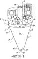
- FIG. 4is a perspective view of a swashplate type compressor that includes an oil separator in accordance with the present invention.
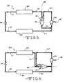
- FIG. 5is a schematic representation of a preferred embodiment of a refrigeration circuit in accordance with the present invention.
- FIG. 6is a schematic representation of an alternate embodiment of a refrigeration circuit in accordance with the present invention.
- FIGS. 1, 2 , and 3illustrate exemplary embodiments of the oil separator of the present invention.
- the present inventionprovides an oil separator, generally indicated in the figures at reference 10 .
- the oil separatorcomprises an upper portion 12 , one or more inlet passages 14 connected to the upper portion 12 , a first outlet passage 16 , a lower portion 18 , and a second outlet passage 20 .
- a mist containing oil suspended in a gaseous mediumis discharged by a compressor and enters the oil separator 10 through the inlet passage(s) 14 .
- the mistbegins to swirl downward in the upper portion 12 of the oil separator 10 .
- the swirlingcreates a centrifugal force on the mist, forcing the heavier oil droplets onto the inner surface of the upper portion 12 , thereby separating the oil from the refrigerant.
- the gaseous refrigerantis able to escape by passing through the first outlet passage 16 .
- a decreasing cross-sectional diameter 22increases the velocity of the swirl, thereby increasing the centrifugal force.
- the separated oileventually exits the oil separator 10 through the second outlet passage 20 .
- the upper portion 12preferably comprises a cylindrical portion.
- the upper portion 12has a circumferential wall 24 and two ends 26 , 28 .
- the first end 26faces the exterior of the oil separator 10 and the second end 28 faces the lower portion 18 .
- An upper wall 30preferably closes the first end 26 of the upper portion 12 , except for the inlet passage(s) 14 .
- the second end 28is preferably completely open.
- the upper portion 12defines an open interior cavity 32 .
- the lower portion 18is in communication with the cavity 32 of the upper portion 12 .
- the entire oil separator 10preferably defines a main interior chamber 34 that comprises the cavity 32 of the upper portion 12 and the interior of the lower portion 18 .
- the inlet passage 14is adapted to communicate with a compressor and the cavity 32 of the upper portion 12 .
- a plurality of inlet passage(s) 14are defined by the upper portion 12 .
- the inlet passages 14are disposed on the upper end 26 of the upper portion 12 .
- each inlet 14comprises a tubular passage having an entry 36 , an exit 38 , and an interior passageway 40 .
- the entry 36is in communication with the compressor, and the exit 38 provides the through opening by which the inlet passage 14 enters the upper portion 12 .
- the inlet passage 14is preferably angled with respect to the upper wall 30 . As shown in FIG.
- each tubular inlet passage 14traverses the upper wall 30 at an angle to the plane of the upper wall 30 .
- the presence of this anglefacilitates swirling within the oil separator by ensuring that the gas and oil mixture is traveling toward the lower portion 18 and second outlet passage 20 .
- the angle of the inlet passage with respect to the upper wallcan vary, but an angle of 30-60° is preferred. Particularly preferred is an angle of approximately 45°.
- FIGS. 2 and 3illustrate oil separators having alternate forms for the inlet passages.
- the oil separator 110 of this embodimentincludes a cylindrical portion 112 , and inlet passage 114 , a first outlet 116 , a lower portion 118 , a second outlet 120 , a decreasing cross-sectional diameter 122 , a circumferential wall 124 , a top end 126 , a bottom end 128 , an upper wall 130 , an interior cavity 132 , an interior chamber 134 , an inlet entry 136 , an inlet exit 138 , an inlet passageway 140 , an inner opening 142 , an outer opening 144 , a wide end 156 , a narrow end 158 , a taper portion 160 , an annular surface 162 , an a through opening 164 .
- the inlet passage 114comprises a slotted opening in the upper wall 130 . Again, a plurality of these inlet passages 114 is preferably disposed on the upper wall 130 .
- the oil separator 210includes a cylindrical portion 212 , an inlet passage 214 , a first outlet 216 , a lower portion 218 , a second outlet 220 , a decreasing cross-sectional diameter 222 , a circumferential wall 224 , a top end 226 , a bottom end 228 , an upper wall 230 , an interior cavity 232 , an interior chamber 234 , an inlet entry 236 , an inlet exit 238 , an inlet passageway 240 , an inner opening 242 , an outer opening 244 , a wide end 256 , a narrow end 258 , a taper portion 260 , an annular surface 262 , and a through opening 264 .
- the inlet passage 214comprises an annular opening having a series of vanes 215 that divide the passage 214 into a plurality of individual passages.
- the inlet passages 114 , 214are preferably angled with respect to the upper wall 130 , 230 , as detailed above.
- the inlet passage 14traverses the upper wall 30 .
- the first outlet passage 16allows the refrigerant to escape the oil separator 10 .
- the first outlet passage 16is disposed within the oil separator 10 and is in communication with both the interior chamber 34 of the oil separator 10 and the exterior of the oil separator 10 .
- the first outlet passage 16has inner 42 and outer 44 openings.
- the inner opening 42allows communication with the interior chamber 34 of the oil separator 10
- the outer opening 44allows communication with the exterior of the oil separator 10 .
- the first outlet passage 16is preferably a tubular shaped member.
- the first outlet passage 16extends through the upper wall 30 into the interior chamber 34 of the oil separator 10 .
- the first outlet passage 16extends coaxially with the axis of the upper portion 12 .
- the first outlet passage 16can be positioned at an angle to the axis.
- the outer opening 44 of the first outlet passage 16can be defined by the upper wall 30 of the upper portion 12 (i.e., the first outlet passage 16 does not extend beyond the upper wall).
- the lower portion 18 of the oil separatoris located below the upper portion 12 relative to the inlet passage 14 .
- the lower portion 18defines a chamber having at least one section that decreases in its cross-sectional size 22 .
- the lower portion 18can take on a variety of shapes, including concave, convex, bulbous, pyramidal, hyperbolic and conical forms.
- the lower portion 18comprises a conical portion.
- the lower portion 18can comprise any shape that has at least a portion with a decreasing cross-sectional size, which allows for an increase in the velocity of the swirl within the oil separator 10 .
- the cross-sectional size 22 of the lower portion 18decreases gradually, such as with a conical or bulbous shape, from the top of the lower portion 18 (i.e., the region adjacent the cylindrical portion 12 ) to the bottom.
- the cross-section 22can decrease in a quantum manner, such as with a chamber having an interior stair-step profile.
- a helical groove in the interior surfacecould be utilized.
- the conical portion 18comprises a wide end 56 and a narrow end 58 with a taper portion 60 between the two ends 56 , 58 .
- the conical shapeprovides a gradually decreasing cross-sectional size 22 to the interior of the oil separator 10 , thereby allowing the swirl of the mixture to increase in velocity as it travels downward in the oil separator 10 .
- the wide end 56 of the conical portion 18is in communication with the interior cavity 32 of the upper portion 12 .
- the interior of the entire oil separator 10except for the refrigerant outlet, essentially comprises a hollow interior chamber 34 .
- the decreasing diameter of the lower portion 18functions to increase the velocity of the swirl within the oil separator 10 .
- various other elementscould be utilized to accomplish this function.
- a swirling gas or fluid within the oil separator 10a rotating blade or propeller, or a fan disposed within the oil separator could all be employed to increase the velocity of the swirl within the oil separator 10 .
- the narrow end 58 of the lower portion 18defines a second outlet passage 20 .
- the second outlet passage 20communicates with the exterior of the oil separator 10 , and provides the means by which the oil leaves the oil separator 10 .
- the second outlet passage 20is in communication with a passageway that allows the oil to ultimately return to the compressor
- the second outlet passagecan be positioned at any point on the lower portion 18 . It is preferred that the second outlet passage 20 be positioned within an area of the lower portion 18 at which a high degree of oil concentration occurs.
- the second outlet passage 20comprises an annular surface 62 with a centrally located through-opening 64 .
- the second outlet passage 20lies on a plane at an angle to the plane defined by the second end of the cylindrical portion.
- the second outlet passage 20can be positioned parallel to this plane.
- the annular surfacecan be eliminated from the second outlet passage.
- the second outlet passagecomprises a through-opening defined by the wall of the lower portion.
- Oil separators in accordance with the present inventioncan be used in conjunction with a variety of compressors.
- Swashplate type compressorsare frequently used in the refrigeration circuit of automobiles. These compressors are known in the art, and will not be described in detail herein.
- Typical swashplate compressorsare described in the following U.S. Patents, each of which is herein incorporated by reference in its entirety: U.S. Pat. No. 4,996,841 to Meijer et al. for a STIRLING CYCLE HEAT PUMP FOR HEATING AND/OR COOLING SYSTEMS, U.S. Pat. No. 5,816,134 to Takenaka et al. for COMPRESSOR PISTON AND PISTON TYPE COMPRESSOR, and U.S.
- FIG. 4illustrates a swashplate type compressor 66 incorporating the oil separator 10 of the present invention.
- the swashplate type compressor 66comprises a housing 68 that defines a swashplate chamber 70 and at least one cylinder bore 72 .
- a rotatable driveshaft 74passes through the housing 68 and into the swashplate chamber 70 .
- the swashplate 76is fixedly attached to the end of the shaft 74 at an angle within the chamber 70 .
- a piston 78is positioned in the cylinder bore 72 and, via shoes 80 , is operably connected to the swashplate 76 such that the rotational movement of the shaft 74 and connected swashplate 76 forces the piston 78 to reciprocate in a linear fashion within the cylinder bore 72 .
- This reciprocating movement of the piston 78results in the compression of gas contained within the cylinder bore 72 as the piston 78 moves between a top dead center position and bottom dead center position.
- a discharge outlet 82is in communication with the cylinder 72 such that the compressed gas is forced into the discharge outlet 82 and can be moved into the remainder of a refrigeration circuit.
- the compressor 66includes an oil return inlet 84 for returning lubricating oil to the swashplate chamber 70 such that it is available for lubricating the moving parts located within the swashplate chamber 70 .
- the oil separator 10is preferably positioned such that the inlet passage 14 is in communication with the discharge outlet 82 and the second outlet passage 20 is in communication with the oil return inlet 84 .
- the first outlet passage 16is connected to the remainder of the refrigeration circuit such that the refrigerant after being separated from the oil, can be moved into the remainder of the circuit. In this fashion, a mist containing oil suspended in a gaseous refrigerant leaves the compressor 66 through the discharge outlet 82 and enters the oil separator 10 through the inlet passage 14 at a flow rate sufficient to enable swirling within the oil separator 10 . While in the oil separator 10 , a swirl and resultant centrifugal force are created and the oil is gradually separated from the refrigerant.
- the refrigerantleaves the oil separator 10 through the first outlet passage 16 and is able to travel through the rest of the refrigeration circuit.
- the oilgradually leaves the oil separator 10 through the second outlet passage 20 , and returns to the compressor 66 through the oil return inlet 84 .
- the oil separator 10 of the present inventionis particularly well suited for incorporation into refrigeration circuits. These circuits are well know in the art and will not be described in detail herein. Typically, such circuits include at least a compressor, a condenser, an expansion device, an evaporator, and communicative elements disposed between these elements.
- FIG. 5illustrates a preferred embodiment of a refrigeration circuit 300 incorporating an oil separator in accordance with the present invention.
- the circuitincludes a compressor 302 , a condenser 304 , an expansion valve 306 , an evaporator 308 , an oil separator 310 in accordance with the present invention, and communicative passageways 312 between these elements.
- the oil separator 310includes a plurality of inlet passages, as in the embodiments illustrated in FIGS. 1, 2 , and 3
- the circuit 300also preferably includes a connector 314 that divides the oil and refrigerant mixture into an appropriate number of separate streams.
- the vanes of the inlet passageas shown in FIG. 3, can comprise the divided passageway.
- the oil separator 310is able to generate high centrifugal force on the oil and refrigerant mixture regardless of the orientation of the oil separator 310 .
- the oil separator 310can be mounted at any orientation with respect to the compressor 302 .
- the oil separator 310is mounted vertically with respect to the compressor 302 .
- the oil separator 310is mounted such that the lengthwise axis 316 of the oil separator 310 is substantially perpendicular to a lengthwise axis 318 of the shaft of the compressor 302 .
- the lengthwise axis 316 of the oil separatorextends from the second outlet passage to the upper wall.
- the lengthwise axis 318 of the compressorrefers to an axis extending along the line of the crankshaft of the compressor.
- the oil separator 310can be mounted at different angles with respect to the compressor 302 .
- the oil separator 310can be mounted horizontally. That is, the oil separator can be mounted such that its lengthwise axis 316 is substantially parallel to the lengthwise axis 318 of the shaft of the compressor 302 .
- the oil separator of the present inventioncan be formed by standard techniques, such as stamping and welding, and secured to the compressor with connections being made to the inlet passage, first outlet passage and second outlet passage.
- the oil separator of the present inventionis integrally formed by the compressor housing.
- the oil separatoris machined into the, housing of the compressor.
- the communicative passageways between the compressor and the inlet, first outlet and second outlet passagescan also be integrally formed by the housing. Alternatively, these communicative passageways can comprise separately attached members.
- the components of the oil compressorcan be fabricated from steel, aluminum, or any other suitable metal or material.
Landscapes
- Engineering & Computer Science (AREA)
- Mechanical Engineering (AREA)
- General Engineering & Computer Science (AREA)
- Chemical & Material Sciences (AREA)
- Analytical Chemistry (AREA)
- Power Engineering (AREA)
- Physics & Mathematics (AREA)
- Thermal Sciences (AREA)
- Compressor (AREA)
- Compressors, Vaccum Pumps And Other Relevant Systems (AREA)
Abstract
Description
Claims (16)
Priority Applications (2)
| Application Number | Priority Date | Filing Date | Title |
|---|---|---|---|
| US09/954,871US6497114B1 (en) | 2001-09-18 | 2001-09-18 | Oil separator |
| DE10244588ADE10244588B4 (en) | 2001-09-18 | 2002-09-17 | oil separator |
Applications Claiming Priority (1)
| Application Number | Priority Date | Filing Date | Title |
|---|---|---|---|
| US09/954,871US6497114B1 (en) | 2001-09-18 | 2001-09-18 | Oil separator |
Publications (1)
| Publication Number | Publication Date |
|---|---|
| US6497114B1true US6497114B1 (en) | 2002-12-24 |
Family
ID=25496045
Family Applications (1)
| Application Number | Title | Priority Date | Filing Date |
|---|---|---|---|
| US09/954,871Expired - LifetimeUS6497114B1 (en) | 2001-09-18 | 2001-09-18 | Oil separator |
Country Status (2)
| Country | Link |
|---|---|
| US (1) | US6497114B1 (en) |
| DE (1) | DE10244588B4 (en) |
Cited By (17)
| Publication number | Priority date | Publication date | Assignee | Title |
|---|---|---|---|---|
| US20040221610A1 (en)* | 2003-05-08 | 2004-11-11 | Yoshinari Yamada | Oil separation structure for refrigerant compressor |
| US20050072307A1 (en)* | 2003-10-06 | 2005-04-07 | Visteon Global Technologies, Inc. | Oil separator for a compressor |
| EP1568955A1 (en)* | 2004-02-25 | 2005-08-31 | Lg Electronics Inc. | Oil separator and cooling-cycle apparatus using the same |
| US20070020132A1 (en)* | 2005-07-06 | 2007-01-25 | Visteon Global Technologies, Inc. | NVH and gas pulsation reduction in AC compressor |
| US20080072750A1 (en)* | 2006-09-27 | 2008-03-27 | Michael Gregory Theodore | Oil separator for a fluid displacement apparatus |
| WO2010097537A1 (en)* | 2009-02-27 | 2010-09-02 | Danfoss Commercial Compressors | Device for separating a lubricant from a refrigerant lubricant/gas mixture discharged from at least one refrigerating compressor |
| US20110011105A1 (en)* | 2007-07-12 | 2011-01-20 | Johnson Controls Technology Company | Oil separator |
| US20110113819A1 (en)* | 2008-06-27 | 2011-05-19 | Yuuichi Matsumoto | Refrigeration Cycle |
| US20110120176A1 (en)* | 2009-11-23 | 2011-05-26 | Denso International America, Inc. | Variable displacement compressor shaft oil separator |
| EP2614216A4 (en)* | 2010-09-09 | 2016-12-14 | Dresser-Rand Company | Flush-enabled controlled flow drain |
| JP2018155485A (en)* | 2017-03-17 | 2018-10-04 | 日冷工業株式会社 | Gas-liquid separator and refrigeration apparatus equipped with gas-liquid separator |
| CN111005873A (en)* | 2019-12-23 | 2020-04-14 | 珠海格力节能环保制冷技术研究中心有限公司 | Oil-gas separator and horizontal compressor with same |
| CN114458419A (en)* | 2022-01-30 | 2022-05-10 | 西北工业大学 | Oil-gas separator with spiral inlet flow channel |
| US11353250B2 (en)* | 2020-01-10 | 2022-06-07 | Heatcraft Refrigeration Products Llc | Vertical oil separator |
| CN115006933A (en)* | 2022-05-13 | 2022-09-06 | 上海铂钺制冷科技有限公司 | Oil-gas separator with built-in blade type fluid director and conical oil collector |
| CN115614279A (en)* | 2021-07-13 | 2023-01-17 | 上海海立电器有限公司 | Compressor |
| CN120487616A (en)* | 2025-07-17 | 2025-08-15 | 珠海凌达压缩机有限公司 | Oil separation structure and compressor |
Families Citing this family (3)
| Publication number | Priority date | Publication date | Assignee | Title |
|---|---|---|---|---|
| JP5413850B2 (en) | 2010-12-24 | 2014-02-12 | サンデン株式会社 | Refrigerant compressor |
| ES2904309T3 (en)* | 2017-09-28 | 2022-04-04 | Mitsubishi Electric Corp | oil separator and air conditioner with the same |
| DE102020200775A1 (en) | 2020-01-23 | 2021-07-29 | Volkswagen Aktiengesellschaft | Gas cyclone oil separator and air conditioning device for a motor vehicle |
Citations (18)
| Publication number | Priority date | Publication date | Assignee | Title |
|---|---|---|---|---|
| US3504804A (en)* | 1967-09-26 | 1970-04-07 | Ajem Lab Inc | Centrifugal separator |
| US4097358A (en)* | 1976-08-30 | 1978-06-27 | Diamond Shamrock Corporation | Apparatus for release of an entrained gas in a liquid medium |
| US4255099A (en) | 1977-12-29 | 1981-03-10 | Seiko Keiki Kabushiki Kaisha | Oil separator for compressor |
| US4906264A (en)* | 1989-09-13 | 1990-03-06 | Vilter Manufacturing Corporation | Oil separator for separating and collecting oil entrained in refrigerant |
| US4996841A (en) | 1989-08-02 | 1991-03-05 | Stirling Thermal Motors, Inc. | Stirling cycle heat pump for heating and/or cooling systems |
| US5159820A (en) | 1989-07-05 | 1992-11-03 | Nippondenso Co., Ltd. | Oil separator integrally mounted on compressor |
| US5404730A (en)* | 1992-08-20 | 1995-04-11 | Ac&R Components, Inc. | Helical oil separator |
| US5636974A (en) | 1995-06-08 | 1997-06-10 | Kabushiki Kaisha Toyoda Jidoshokki Seisakusho | Reciprocating piston type compressor with an oil separator for removing lubricating oil from discharged high pressure refrigerant gas |
| US5718566A (en)* | 1995-05-25 | 1998-02-17 | Kabushiki Kaisha Toyoda Jidoshokki Seisakusho | Drive shaft lubrication arrangement for a swash plate type refrigerant compressor |
| US5795139A (en)* | 1995-03-17 | 1998-08-18 | Kabushiki Kaisha Toyoda Jidoshokki Seisakusho | Swash plate type refrigerant compressor with improved internal lubricating system |
| US5816134A (en) | 1995-06-05 | 1998-10-06 | Kabushiki Kaisha Toyoda Jidoshokki Seisakusho | Compressor piston and piston type compressor |
| US5921756A (en) | 1995-12-04 | 1999-07-13 | Denso Corporation | Swash plate compressor including double-headed pistons having piston sections with different cross-sectional areas |
| US6010320A (en) | 1997-07-30 | 2000-01-04 | Kwon; Hee-Sung | Compressor system having an oil separator |
| US6015269A (en)* | 1996-12-10 | 2000-01-18 | Kabushiki Kaisha Toyoda Jidoshokki Seisakusho | Variable displacement compressor |
| US6129775A (en)* | 1998-08-19 | 2000-10-10 | G.B.D. Corp. | Terminal insert for a cyclone separator |
| US6134898A (en)* | 1998-07-09 | 2000-10-24 | Kabushiki Kaisha Toyoda Jidoshokki Seisakusho | Positive-displacement-type refrigerant compressor with a novel oil-separating and lubricating system |
| US20020025258A1 (en)* | 2000-04-07 | 2002-02-28 | Masaki Ota | Variable displacement compressors |
| US6376732B1 (en)* | 2000-03-08 | 2002-04-23 | Shell Oil Company | Wetted wall vapor/liquid separator |
Family Cites Families (2)
| Publication number | Priority date | Publication date | Assignee | Title |
|---|---|---|---|---|
| DE2650935C3 (en)* | 1976-11-08 | 1981-10-15 | Danfoss A/S, 6430 Nordborg | Refrigeration machine with encapsulated motor compressor |
| US6481240B2 (en)* | 2001-02-01 | 2002-11-19 | Visteon Global Technologies, Inc. | Oil separator |
- 2001
- 2001-09-18USUS09/954,871patent/US6497114B1/ennot_activeExpired - Lifetime
- 2002
- 2002-09-17DEDE10244588Apatent/DE10244588B4/ennot_activeExpired - Lifetime
Patent Citations (18)
| Publication number | Priority date | Publication date | Assignee | Title |
|---|---|---|---|---|
| US3504804A (en)* | 1967-09-26 | 1970-04-07 | Ajem Lab Inc | Centrifugal separator |
| US4097358A (en)* | 1976-08-30 | 1978-06-27 | Diamond Shamrock Corporation | Apparatus for release of an entrained gas in a liquid medium |
| US4255099A (en) | 1977-12-29 | 1981-03-10 | Seiko Keiki Kabushiki Kaisha | Oil separator for compressor |
| US5159820A (en) | 1989-07-05 | 1992-11-03 | Nippondenso Co., Ltd. | Oil separator integrally mounted on compressor |
| US4996841A (en) | 1989-08-02 | 1991-03-05 | Stirling Thermal Motors, Inc. | Stirling cycle heat pump for heating and/or cooling systems |
| US4906264A (en)* | 1989-09-13 | 1990-03-06 | Vilter Manufacturing Corporation | Oil separator for separating and collecting oil entrained in refrigerant |
| US5404730A (en)* | 1992-08-20 | 1995-04-11 | Ac&R Components, Inc. | Helical oil separator |
| US5795139A (en)* | 1995-03-17 | 1998-08-18 | Kabushiki Kaisha Toyoda Jidoshokki Seisakusho | Swash plate type refrigerant compressor with improved internal lubricating system |
| US5718566A (en)* | 1995-05-25 | 1998-02-17 | Kabushiki Kaisha Toyoda Jidoshokki Seisakusho | Drive shaft lubrication arrangement for a swash plate type refrigerant compressor |
| US5816134A (en) | 1995-06-05 | 1998-10-06 | Kabushiki Kaisha Toyoda Jidoshokki Seisakusho | Compressor piston and piston type compressor |
| US5636974A (en) | 1995-06-08 | 1997-06-10 | Kabushiki Kaisha Toyoda Jidoshokki Seisakusho | Reciprocating piston type compressor with an oil separator for removing lubricating oil from discharged high pressure refrigerant gas |
| US5921756A (en) | 1995-12-04 | 1999-07-13 | Denso Corporation | Swash plate compressor including double-headed pistons having piston sections with different cross-sectional areas |
| US6015269A (en)* | 1996-12-10 | 2000-01-18 | Kabushiki Kaisha Toyoda Jidoshokki Seisakusho | Variable displacement compressor |
| US6010320A (en) | 1997-07-30 | 2000-01-04 | Kwon; Hee-Sung | Compressor system having an oil separator |
| US6134898A (en)* | 1998-07-09 | 2000-10-24 | Kabushiki Kaisha Toyoda Jidoshokki Seisakusho | Positive-displacement-type refrigerant compressor with a novel oil-separating and lubricating system |
| US6129775A (en)* | 1998-08-19 | 2000-10-10 | G.B.D. Corp. | Terminal insert for a cyclone separator |
| US6376732B1 (en)* | 2000-03-08 | 2002-04-23 | Shell Oil Company | Wetted wall vapor/liquid separator |
| US20020025258A1 (en)* | 2000-04-07 | 2002-02-28 | Masaki Ota | Variable displacement compressors |
Cited By (30)
| Publication number | Priority date | Publication date | Assignee | Title |
|---|---|---|---|---|
| US7204098B2 (en) | 2003-05-08 | 2007-04-17 | Kabushiki Kaisha Toyota Jidoshokki | Oil separation structure for refrigerant compressor |
| US20040221610A1 (en)* | 2003-05-08 | 2004-11-11 | Yoshinari Yamada | Oil separation structure for refrigerant compressor |
| EP1477670A3 (en)* | 2003-05-08 | 2006-01-11 | Kabushiki Kaisha Toyota Jidoshokki | Oil separation structure for refrigerant compressor |
| SG119219A1 (en)* | 2003-05-08 | 2006-02-28 | Toyota Jidoshokki Kk | Oil separation structure for refrigerant compressor |
| US20050072307A1 (en)* | 2003-10-06 | 2005-04-07 | Visteon Global Technologies, Inc. | Oil separator for a compressor |
| US7060122B2 (en) | 2003-10-06 | 2006-06-13 | Visteon Global Technologies, Inc. | Oil separator for a compressor |
| US7386994B2 (en) | 2004-02-25 | 2008-06-17 | Lg Electronics Inc. | Oil separator and cooling-cycle apparatus using the same |
| US20060112724A1 (en)* | 2004-02-25 | 2006-06-01 | Lg Electronics Inc. | Oil separator and cooling-cycle apparatus using the same |
| EP1568955A1 (en)* | 2004-02-25 | 2005-08-31 | Lg Electronics Inc. | Oil separator and cooling-cycle apparatus using the same |
| US20070020132A1 (en)* | 2005-07-06 | 2007-01-25 | Visteon Global Technologies, Inc. | NVH and gas pulsation reduction in AC compressor |
| US7494328B2 (en) | 2005-07-06 | 2009-02-24 | Visteon Global Technologies, Inc. | NVH and gas pulsation reduction in AC compressor |
| US20080072750A1 (en)* | 2006-09-27 | 2008-03-27 | Michael Gregory Theodore | Oil separator for a fluid displacement apparatus |
| US7520210B2 (en) | 2006-09-27 | 2009-04-21 | Visteon Global Technologies, Inc. | Oil separator for a fluid displacement apparatus |
| US8429930B2 (en)* | 2007-07-12 | 2013-04-30 | Johnson Controls Technology Company | Oil separator |
| US20110011105A1 (en)* | 2007-07-12 | 2011-01-20 | Johnson Controls Technology Company | Oil separator |
| US20110113819A1 (en)* | 2008-06-27 | 2011-05-19 | Yuuichi Matsumoto | Refrigeration Cycle |
| FR2942656A1 (en)* | 2009-02-27 | 2010-09-03 | Danfoss Commercial Compressors | DEVICE FOR SEPARATING LUBRICANT FROM A LUBRICANT-REFRIGERATING GAS MIXTURE |
| WO2010097537A1 (en)* | 2009-02-27 | 2010-09-02 | Danfoss Commercial Compressors | Device for separating a lubricant from a refrigerant lubricant/gas mixture discharged from at least one refrigerating compressor |
| US9207005B2 (en) | 2009-02-27 | 2015-12-08 | Danfoss Commercial Compressors | Device for separating lubricant from a lubricant-refrigerating gas mixture discharged from at least one refrigerant compressor |
| US20110120176A1 (en)* | 2009-11-23 | 2011-05-26 | Denso International America, Inc. | Variable displacement compressor shaft oil separator |
| US8348632B2 (en) | 2009-11-23 | 2013-01-08 | Denso International America, Inc. | Variable displacement compressor shaft oil separator |
| EP2614216A4 (en)* | 2010-09-09 | 2016-12-14 | Dresser-Rand Company | Flush-enabled controlled flow drain |
| JP2018155485A (en)* | 2017-03-17 | 2018-10-04 | 日冷工業株式会社 | Gas-liquid separator and refrigeration apparatus equipped with gas-liquid separator |
| CN111005873A (en)* | 2019-12-23 | 2020-04-14 | 珠海格力节能环保制冷技术研究中心有限公司 | Oil-gas separator and horizontal compressor with same |
| US11353250B2 (en)* | 2020-01-10 | 2022-06-07 | Heatcraft Refrigeration Products Llc | Vertical oil separator |
| CN115614279A (en)* | 2021-07-13 | 2023-01-17 | 上海海立电器有限公司 | Compressor |
| CN114458419A (en)* | 2022-01-30 | 2022-05-10 | 西北工业大学 | Oil-gas separator with spiral inlet flow channel |
| CN115006933A (en)* | 2022-05-13 | 2022-09-06 | 上海铂钺制冷科技有限公司 | Oil-gas separator with built-in blade type fluid director and conical oil collector |
| CN115006933B (en)* | 2022-05-13 | 2023-11-03 | 上海铂钺制冷科技有限公司 | Oil-gas separator with built-in vane type fluid director and conical oil collector |
| CN120487616A (en)* | 2025-07-17 | 2025-08-15 | 珠海凌达压缩机有限公司 | Oil separation structure and compressor |
Also Published As
| Publication number | Publication date |
|---|---|
| DE10244588B4 (en) | 2008-11-27 |
| DE10244588A1 (en) | 2003-04-24 |
Similar Documents
| Publication | Publication Date | Title |
|---|---|---|
| US6497114B1 (en) | Oil separator | |
| KR100266248B1 (en) | Variable volume compressor | |
| US4392788A (en) | Swash-plate type compressor having oil separating function | |
| US5733107A (en) | Lubricant oil separating mechanism for a compressor | |
| US3781135A (en) | Refrigerant compressor for vehicles | |
| US7066722B2 (en) | Discharge valve for compressor | |
| US6481240B2 (en) | Oil separator | |
| EP1798499A2 (en) | Refrigerant compressor having an oil separator | |
| JP2006329621A (en) | Oil separator-muffler structure | |
| KR20020038464A (en) | Capacity variable type compressor | |
| JPH10196540A (en) | Compressor | |
| US6206648B1 (en) | Compressor | |
| US5159820A (en) | Oil separator integrally mounted on compressor | |
| US8991296B2 (en) | Compressor | |
| US20100101269A1 (en) | Compressor with improved oil separation | |
| US6494930B2 (en) | Oil separator having a tortuous path disposed between an inlet and first outlet | |
| US20070175239A1 (en) | Refrigerant compressor | |
| JPH02230979A (en) | Swash plate type compressor | |
| US6726456B2 (en) | Foreign matter removing structure in a fluid circuit and a compressor therewith | |
| US7060122B2 (en) | Oil separator for a compressor | |
| WO2012086347A1 (en) | Refrigerant compressor | |
| US20030210989A1 (en) | Compressors | |
| KR100490320B1 (en) | Reciprocating piston type refrigerant compressor | |
| KR20000047339A (en) | Oil separator including compressor | |
| US6705204B2 (en) | Swash plate-type |
Legal Events
| Date | Code | Title | Description |
|---|---|---|---|
| AS | Assignment | Owner name:VISTEON GLOBAL TECHNOLOGIES, INC., MICHIGAN Free format text:ASSIGNMENT OF ASSIGNORS INTEREST;ASSIGNORS:STRIKIS, GUNTIS VIKTORS;BHATIA, KANWAL;PITLA, SRINIVAS;AND OTHERS;REEL/FRAME:012182/0469;SIGNING DATES FROM 20010802 TO 20010820 | |
| STCF | Information on status: patent grant | Free format text:PATENTED CASE | |
| FPAY | Fee payment | Year of fee payment:4 | |
| AS | Assignment | Owner name:JPMORGAN CHASE BANK, N.A., AS ADMINISTRATIVE AGENT Free format text:SECURITY AGREEMENT;ASSIGNOR:VISTEON GLOBAL TECHNOLOGIES, INC.;REEL/FRAME:020497/0733 Effective date:20060613 | |
| AS | Assignment | Owner name:JPMORGAN CHASE BANK, TEXAS Free format text:SECURITY INTEREST;ASSIGNOR:VISTEON GLOBAL TECHNOLOGIES, INC.;REEL/FRAME:022368/0001 Effective date:20060814 Owner name:JPMORGAN CHASE BANK,TEXAS Free format text:SECURITY INTEREST;ASSIGNOR:VISTEON GLOBAL TECHNOLOGIES, INC.;REEL/FRAME:022368/0001 Effective date:20060814 | |
| AS | Assignment | Owner name:WILMINGTON TRUST FSB, AS ADMINISTRATIVE AGENT, MIN Free format text:ASSIGNMENT OF SECURITY INTEREST IN PATENTS;ASSIGNOR:JPMORGAN CHASE BANK, N.A., AS ADMINISTRATIVE AGENT;REEL/FRAME:022575/0186 Effective date:20090415 Owner name:WILMINGTON TRUST FSB, AS ADMINISTRATIVE AGENT,MINN Free format text:ASSIGNMENT OF SECURITY INTEREST IN PATENTS;ASSIGNOR:JPMORGAN CHASE BANK, N.A., AS ADMINISTRATIVE AGENT;REEL/FRAME:022575/0186 Effective date:20090415 | |
| AS | Assignment | Owner name:THE BANK OF NEW YORK MELLON, AS ADMINISTRATIVE AGE Free format text:ASSIGNMENT OF PATENT SECURITY INTEREST;ASSIGNOR:JPMORGAN CHASE BANK, N.A., A NATIONAL BANKING ASSOCIATION;REEL/FRAME:022974/0057 Effective date:20090715 | |
| FPAY | Fee payment | Year of fee payment:8 | |
| AS | Assignment | Owner name:VISTEON GLOBAL TECHNOLOGIES, INC., MICHIGAN Free format text:RELEASE BY SECURED PARTY AGAINST SECURITY INTEREST IN PATENTS RECORDED AT REEL 022974 FRAME 0057;ASSIGNOR:THE BANK OF NEW YORK MELLON;REEL/FRAME:025095/0711 Effective date:20101001 | |
| AS | Assignment | Owner name:VISTEON GLOBAL TECHNOLOGIES, INC., MICHIGAN Free format text:RELEASE BY SECURED PARTY AGAINST SECURITY INTEREST IN PATENTS RECORDED AT REEL 022575 FRAME 0186;ASSIGNOR:WILMINGTON TRUST FSB, AS ADMINISTRATIVE AGENT;REEL/FRAME:025105/0201 Effective date:20101001 | |
| AS | Assignment | Owner name:MORGAN STANLEY SENIOR FUNDING, INC., AS AGENT, NEW Free format text:SECURITY AGREEMENT;ASSIGNORS:VISTEON CORPORATION;VC AVIATION SERVICES, LLC;VISTEON ELECTRONICS CORPORATION;AND OTHERS;REEL/FRAME:025241/0317 Effective date:20101007 Owner name:MORGAN STANLEY SENIOR FUNDING, INC., AS AGENT, NEW Free format text:SECURITY AGREEMENT (REVOLVER);ASSIGNORS:VISTEON CORPORATION;VC AVIATION SERVICES, LLC;VISTEON ELECTRONICS CORPORATION;AND OTHERS;REEL/FRAME:025238/0298 Effective date:20101001 | |
| AS | Assignment | Owner name:VISTEON CORPORATION, MICHIGAN Free format text:RELEASE BY SECURED PARTY AGAINST SECURITY INTEREST IN PATENTS ON REEL 025241 FRAME 0317;ASSIGNOR:MORGAN STANLEY SENIOR FUNDING, INC.;REEL/FRAME:026178/0412 Effective date:20110406 Owner name:VISTEON INTERNATIONAL HOLDINGS, INC., MICHIGAN Free format text:RELEASE BY SECURED PARTY AGAINST SECURITY INTEREST IN PATENTS ON REEL 025241 FRAME 0317;ASSIGNOR:MORGAN STANLEY SENIOR FUNDING, INC.;REEL/FRAME:026178/0412 Effective date:20110406 Owner name:VISTEON EUROPEAN HOLDING, INC., MICHIGAN Free format text:RELEASE BY SECURED PARTY AGAINST SECURITY INTEREST IN PATENTS ON REEL 025241 FRAME 0317;ASSIGNOR:MORGAN STANLEY SENIOR FUNDING, INC.;REEL/FRAME:026178/0412 Effective date:20110406 Owner name:VISTEON SYSTEMS, LLC, MICHIGAN Free format text:RELEASE BY SECURED PARTY AGAINST SECURITY INTEREST IN PATENTS ON REEL 025241 FRAME 0317;ASSIGNOR:MORGAN STANLEY SENIOR FUNDING, INC.;REEL/FRAME:026178/0412 Effective date:20110406 Owner name:VISTEON GLOBAL TECHNOLOGIES, INC., MICHIGAN Free format text:RELEASE BY SECURED PARTY AGAINST SECURITY INTEREST IN PATENTS ON REEL 025241 FRAME 0317;ASSIGNOR:MORGAN STANLEY SENIOR FUNDING, INC.;REEL/FRAME:026178/0412 Effective date:20110406 Owner name:VISTEON ELECTRONICS CORPORATION, MICHIGAN Free format text:RELEASE BY SECURED PARTY AGAINST SECURITY INTEREST IN PATENTS ON REEL 025241 FRAME 0317;ASSIGNOR:MORGAN STANLEY SENIOR FUNDING, INC.;REEL/FRAME:026178/0412 Effective date:20110406 Owner name:VC AVIATION SERVICES, LLC, MICHIGAN Free format text:RELEASE BY SECURED PARTY AGAINST SECURITY INTEREST IN PATENTS ON REEL 025241 FRAME 0317;ASSIGNOR:MORGAN STANLEY SENIOR FUNDING, INC.;REEL/FRAME:026178/0412 Effective date:20110406 Owner name:VISTEON INTERNATIONAL BUSINESS DEVELOPMENT, INC., Free format text:RELEASE BY SECURED PARTY AGAINST SECURITY INTEREST IN PATENTS ON REEL 025241 FRAME 0317;ASSIGNOR:MORGAN STANLEY SENIOR FUNDING, INC.;REEL/FRAME:026178/0412 Effective date:20110406 Owner name:VISTEON GLOBAL TREASURY, INC., MICHIGAN Free format text:RELEASE BY SECURED PARTY AGAINST SECURITY INTEREST IN PATENTS ON REEL 025241 FRAME 0317;ASSIGNOR:MORGAN STANLEY SENIOR FUNDING, INC.;REEL/FRAME:026178/0412 Effective date:20110406 | |
| AS | Assignment | Owner name:HALLA VISTEON CLIMATE CONTROL CORPORATION, KOREA, Free format text:ASSIGNMENT OF ASSIGNORS INTEREST;ASSIGNOR:VISTEON GLOBAL TECHNOLOGIES, INC.;REEL/FRAME:030935/0969 Effective date:20130726 | |
| FPAY | Fee payment | Year of fee payment:12 | |
| AS | Assignment | Owner name:VISTEON INTERNATIONAL BUSINESS DEVELOPMENT, INC., Free format text:RELEASE OF SECURITY INTEREST IN INTELLECTUAL PROPERTY;ASSIGNOR:MORGAN STANLEY SENIOR FUNDING, INC.;REEL/FRAME:033107/0717 Effective date:20140409 Owner name:VISTEON INTERNATIONAL HOLDINGS, INC., MICHIGAN Free format text:RELEASE OF SECURITY INTEREST IN INTELLECTUAL PROPERTY;ASSIGNOR:MORGAN STANLEY SENIOR FUNDING, INC.;REEL/FRAME:033107/0717 Effective date:20140409 Owner name:VISTEON SYSTEMS, LLC, MICHIGAN Free format text:RELEASE OF SECURITY INTEREST IN INTELLECTUAL PROPERTY;ASSIGNOR:MORGAN STANLEY SENIOR FUNDING, INC.;REEL/FRAME:033107/0717 Effective date:20140409 Owner name:VISTEON ELECTRONICS CORPORATION, MICHIGAN Free format text:RELEASE OF SECURITY INTEREST IN INTELLECTUAL PROPERTY;ASSIGNOR:MORGAN STANLEY SENIOR FUNDING, INC.;REEL/FRAME:033107/0717 Effective date:20140409 Owner name:VISTEON EUROPEAN HOLDINGS, INC., MICHIGAN Free format text:RELEASE OF SECURITY INTEREST IN INTELLECTUAL PROPERTY;ASSIGNOR:MORGAN STANLEY SENIOR FUNDING, INC.;REEL/FRAME:033107/0717 Effective date:20140409 Owner name:VC AVIATION SERVICES, LLC, MICHIGAN Free format text:RELEASE OF SECURITY INTEREST IN INTELLECTUAL PROPERTY;ASSIGNOR:MORGAN STANLEY SENIOR FUNDING, INC.;REEL/FRAME:033107/0717 Effective date:20140409 Owner name:VISTEON CORPORATION, MICHIGAN Free format text:RELEASE OF SECURITY INTEREST IN INTELLECTUAL PROPERTY;ASSIGNOR:MORGAN STANLEY SENIOR FUNDING, INC.;REEL/FRAME:033107/0717 Effective date:20140409 Owner name:VISTEON GLOBAL TECHNOLOGIES, INC., MICHIGAN Free format text:RELEASE OF SECURITY INTEREST IN INTELLECTUAL PROPERTY;ASSIGNOR:MORGAN STANLEY SENIOR FUNDING, INC.;REEL/FRAME:033107/0717 Effective date:20140409 Owner name:VISTEON GLOBAL TREASURY, INC., MICHIGAN Free format text:RELEASE OF SECURITY INTEREST IN INTELLECTUAL PROPERTY;ASSIGNOR:MORGAN STANLEY SENIOR FUNDING, INC.;REEL/FRAME:033107/0717 Effective date:20140409 | |
| AS | Assignment | Owner name:HANON SYSTEMS, KOREA, REPUBLIC OF Free format text:CHANGE OF NAME;ASSIGNOR:HALLA VISTEON CLIMATE CONTROL CORPORATION;REEL/FRAME:037007/0103 Effective date:20150728 |