US6496892B1 - Control device with PCMCIA card for communications with field device - Google Patents
Control device with PCMCIA card for communications with field deviceDownload PDFInfo
- Publication number
- US6496892B1 US6496892B1US09/591,730US59173000AUS6496892B1US 6496892 B1US6496892 B1US 6496892B1US 59173000 AUS59173000 AUS 59173000AUS 6496892 B1US6496892 B1US 6496892B1
- Authority
- US
- United States
- Prior art keywords
- control device
- circuit
- controlling
- housing
- dongle
- Prior art date
- Legal status (The legal status is an assumption and is not a legal conclusion. Google has not performed a legal analysis and makes no representation as to the accuracy of the status listed.)
- Expired - Lifetime
Links
Images


Classifications
- H—ELECTRICITY
- H01—ELECTRIC ELEMENTS
- H01R—ELECTRICALLY-CONDUCTIVE CONNECTIONS; STRUCTURAL ASSOCIATIONS OF A PLURALITY OF MUTUALLY-INSULATED ELECTRICAL CONNECTING ELEMENTS; COUPLING DEVICES; CURRENT COLLECTORS
- H01R9/00—Structural associations of a plurality of mutually-insulated electrical connecting elements, e.g. terminal strips or terminal blocks; Terminals or binding posts mounted upon a base or in a case; Bases therefor
- H01R9/22—Bases, e.g. strip, block, panel
- H01R9/24—Terminal blocks
- H01R9/26—Clip-on terminal blocks for side-by-side rail- or strip-mounting
- H01R9/2625—Clip-on terminal blocks for side-by-side rail- or strip-mounting with built-in electrical component
- H01R9/2658—Clip-on terminal blocks for side-by-side rail- or strip-mounting with built-in electrical component with built-in data-bus connection
- G—PHYSICS
- G05—CONTROLLING; REGULATING
- G05B—CONTROL OR REGULATING SYSTEMS IN GENERAL; FUNCTIONAL ELEMENTS OF SUCH SYSTEMS; MONITORING OR TESTING ARRANGEMENTS FOR SUCH SYSTEMS OR ELEMENTS
- G05B19/00—Programme-control systems
- G05B19/02—Programme-control systems electric
- G05B19/04—Programme control other than numerical control, i.e. in sequence controllers or logic controllers
- G05B19/042—Programme control other than numerical control, i.e. in sequence controllers or logic controllers using digital processors
- G05B19/0423—Input/output
- G—PHYSICS
- G05—CONTROLLING; REGULATING
- G05B—CONTROL OR REGULATING SYSTEMS IN GENERAL; FUNCTIONAL ELEMENTS OF SUCH SYSTEMS; MONITORING OR TESTING ARRANGEMENTS FOR SUCH SYSTEMS OR ELEMENTS
- G05B19/00—Programme-control systems
- G05B19/02—Programme-control systems electric
- G05B19/418—Total factory control, i.e. centrally controlling a plurality of machines, e.g. direct or distributed numerical control [DNC], flexible manufacturing systems [FMS], integrated manufacturing systems [IMS] or computer integrated manufacturing [CIM]
- G05B19/4185—Total factory control, i.e. centrally controlling a plurality of machines, e.g. direct or distributed numerical control [DNC], flexible manufacturing systems [FMS], integrated manufacturing systems [IMS] or computer integrated manufacturing [CIM] characterised by the network communication
- G—PHYSICS
- G05—CONTROLLING; REGULATING
- G05B—CONTROL OR REGULATING SYSTEMS IN GENERAL; FUNCTIONAL ELEMENTS OF SUCH SYSTEMS; MONITORING OR TESTING ARRANGEMENTS FOR SUCH SYSTEMS OR ELEMENTS
- G05B2219/00—Program-control systems
- G05B2219/20—Pc systems
- G05B2219/21—Pc I-O input output
- G05B2219/21103—Connect pc to machine, controller, module via PCMCIA
- G—PHYSICS
- G05—CONTROLLING; REGULATING
- G05B—CONTROL OR REGULATING SYSTEMS IN GENERAL; FUNCTIONAL ELEMENTS OF SUCH SYSTEMS; MONITORING OR TESTING ARRANGEMENTS FOR SUCH SYSTEMS OR ELEMENTS
- G05B2219/00—Program-control systems
- G05B2219/20—Pc systems
- G05B2219/25—Pc structure of the system
- G05B2219/25314—Modular structure, modules
- G—PHYSICS
- G05—CONTROLLING; REGULATING
- G05B—CONTROL OR REGULATING SYSTEMS IN GENERAL; FUNCTIONAL ELEMENTS OF SUCH SYSTEMS; MONITORING OR TESTING ARRANGEMENTS FOR SUCH SYSTEMS OR ELEMENTS
- G05B2219/00—Program-control systems
- G05B2219/20—Pc systems
- G05B2219/25—Pc structure of the system
- G05B2219/25322—Stackthrough modules, modules are stacked, no need for backplane
- G—PHYSICS
- G05—CONTROLLING; REGULATING
- G05B—CONTROL OR REGULATING SYSTEMS IN GENERAL; FUNCTIONAL ELEMENTS OF SUCH SYSTEMS; MONITORING OR TESTING ARRANGEMENTS FOR SUCH SYSTEMS OR ELEMENTS
- G05B2219/00—Program-control systems
- G05B2219/20—Pc systems
- G05B2219/25—Pc structure of the system
- G05B2219/25335—Each module has connections to actuator, sensor and to a fieldbus for expansion
- G—PHYSICS
- G05—CONTROLLING; REGULATING
- G05B—CONTROL OR REGULATING SYSTEMS IN GENERAL; FUNCTIONAL ELEMENTS OF SUCH SYSTEMS; MONITORING OR TESTING ARRANGEMENTS FOR SUCH SYSTEMS OR ELEMENTS
- G05B2219/00—Program-control systems
- G05B2219/20—Pc systems
- G05B2219/25—Pc structure of the system
- G05B2219/25336—Cascaded modules, one module connects to other, I-O, computing expansion
- G—PHYSICS
- G05—CONTROLLING; REGULATING
- G05B—CONTROL OR REGULATING SYSTEMS IN GENERAL; FUNCTIONAL ELEMENTS OF SUCH SYSTEMS; MONITORING OR TESTING ARRANGEMENTS FOR SUCH SYSTEMS OR ELEMENTS
- G05B2219/00—Program-control systems
- G05B2219/20—Pc systems
- G05B2219/25—Pc structure of the system
- G05B2219/25428—Field device
- G—PHYSICS
- G05—CONTROLLING; REGULATING
- G05B—CONTROL OR REGULATING SYSTEMS IN GENERAL; FUNCTIONAL ELEMENTS OF SUCH SYSTEMS; MONITORING OR TESTING ARRANGEMENTS FOR SUCH SYSTEMS OR ELEMENTS
- G05B2219/00—Program-control systems
- G05B2219/30—Nc systems
- G05B2219/31—From computer integrated manufacturing till monitoring
- G05B2219/31121—Fielddevice, field controller, interface connected to fieldbus
- G—PHYSICS
- G05—CONTROLLING; REGULATING
- G05B—CONTROL OR REGULATING SYSTEMS IN GENERAL; FUNCTIONAL ELEMENTS OF SUCH SYSTEMS; MONITORING OR TESTING ARRANGEMENTS FOR SUCH SYSTEMS OR ELEMENTS
- G05B2219/00—Program-control systems
- G05B2219/30—Nc systems
- G05B2219/33—Director till display
- G05B2219/33179—Pcmcia
- G—PHYSICS
- G05—CONTROLLING; REGULATING
- G05B—CONTROL OR REGULATING SYSTEMS IN GENERAL; FUNCTIONAL ELEMENTS OF SUCH SYSTEMS; MONITORING OR TESTING ARRANGEMENTS FOR SUCH SYSTEMS OR ELEMENTS
- G05B2219/00—Program-control systems
- G05B2219/30—Nc systems
- G05B2219/33—Director till display
- G05B2219/33273—DCS distributed, decentralised controlsystem, multiprocessor
- G—PHYSICS
- G05—CONTROLLING; REGULATING
- G05B—CONTROL OR REGULATING SYSTEMS IN GENERAL; FUNCTIONAL ELEMENTS OF SUCH SYSTEMS; MONITORING OR TESTING ARRANGEMENTS FOR SUCH SYSTEMS OR ELEMENTS
- G05B2219/00—Program-control systems
- G05B2219/30—Nc systems
- G05B2219/33—Director till display
- G05B2219/33279—Expansion by using secondary access to each module, extension module
- G—PHYSICS
- G05—CONTROLLING; REGULATING
- G05B—CONTROL OR REGULATING SYSTEMS IN GENERAL; FUNCTIONAL ELEMENTS OF SUCH SYSTEMS; MONITORING OR TESTING ARRANGEMENTS FOR SUCH SYSTEMS OR ELEMENTS
- G05B2219/00—Program-control systems
- G05B2219/30—Nc systems
- G05B2219/34—Director, elements to supervisory
- G05B2219/34436—Interface circuit build into connector, dongle
- Y—GENERAL TAGGING OF NEW TECHNOLOGICAL DEVELOPMENTS; GENERAL TAGGING OF CROSS-SECTIONAL TECHNOLOGIES SPANNING OVER SEVERAL SECTIONS OF THE IPC; TECHNICAL SUBJECTS COVERED BY FORMER USPC CROSS-REFERENCE ART COLLECTIONS [XRACs] AND DIGESTS
- Y02—TECHNOLOGIES OR APPLICATIONS FOR MITIGATION OR ADAPTATION AGAINST CLIMATE CHANGE
- Y02P—CLIMATE CHANGE MITIGATION TECHNOLOGIES IN THE PRODUCTION OR PROCESSING OF GOODS
- Y02P90/00—Enabling technologies with a potential contribution to greenhouse gas [GHG] emissions mitigation
- Y02P90/02—Total factory control, e.g. smart factories, flexible manufacturing systems [FMS] or integrated manufacturing systems [IMS]
- Y—GENERAL TAGGING OF NEW TECHNOLOGICAL DEVELOPMENTS; GENERAL TAGGING OF CROSS-SECTIONAL TECHNOLOGIES SPANNING OVER SEVERAL SECTIONS OF THE IPC; TECHNICAL SUBJECTS COVERED BY FORMER USPC CROSS-REFERENCE ART COLLECTIONS [XRACs] AND DIGESTS
- Y10—TECHNICAL SUBJECTS COVERED BY FORMER USPC
- Y10S—TECHNICAL SUBJECTS COVERED BY FORMER USPC CROSS-REFERENCE ART COLLECTIONS [XRACs] AND DIGESTS
- Y10S439/00—Electrical connectors
- Y10S439/942—Comblike retainer for conductor
Definitions
- the inventionrelates generally to the field of digital data processing systems for distributed monitoring and control in industrial environments, and in particular to a compact, modularly expandable controller (called herein a “field controller”) and internal dongles adapted for use with the controller.
- field controllercompact, modularly expandable controller
- internal donglesadapted for use with the controller.
- Distributed control systemsare often used in a number of commercial, industrial and home applications, in particular to monitor and control operations at manufacturing, chemical processing and similar industrial operations, to monitor and control environmental and other factors and so forth.
- a distributed control systemwill typically control machines which facilitate the manufacture and assembly of the products being manufactured.
- a distributed control systemmay control valves to control rates of flow of chemicals into and out of reaction chambers, and monitoring and/or controlling reaction temperatures and pressures and the like which are required to carry out the chemical process.
- distributed control systemsmay perform bookkeeping operations to keep track of the inventory of inputs required for the manufacturing or chemical process, as well as the inventory of outputs produced by the operation.
- Typical distributed control systemsessentially comprise large, centrally-located and expensive computer systems, which can be expensive to maintain and typically have limited expansion capabilities.
- a control systemmay include one or more PCMCIA cards that each couple to a device in the industrial environment, such as, for example, an instrument, monitor, machine or the like. Often, it is advantageous to include an active or passive circuit in the coupling between the controller and the device.
- the cablemay include the circuit. In one arrangement, called a “dongle,” the cable has an encapsulated end portion that includes the active or passive circuit and a connector.
- the inventionprovides a relatively compact, computationally powerful, easily-extendable and easily serviceable field controller for use in a variety of industrial, commercial and home applications.
- a field controllerfor use in a distributed control system with an area controller manages at least one controlled device in an industrial process operation.
- the field controllerincludes a processor module segment through which it can control a selected number of devices.
- the field controllermay also include one or more expansion module segments, each having at least one PCMCIA card coupled to the process control segment to enable it to control a larger number of controlled devices.
- the processor module segmentincludes a processor module and at least one local interface module for interfacing to a controlled device, and the expansion module segment includes interface modules for interfacing to other controlled devices.
- the processor module and the local interface moduleare interconnected by a bus segment, which is also connected to an upstream off-module connector.
- Each expansion module segmentincludes at least one interface module, and also includes a downstream off-module connector and an upstream off-module connector, which are interconnected by a bus segment.
- the downstream off-module connector of each expansion module segmentis adapted to mate with the upstream off-module connector of the processor module segment and of other expansion module segment, so as to facilitate the interconnection of the processor module segment and a sequence of expansion module segments by establishing a unitary multi-drop bus comprising the processor module's bus segment and the bus segments of expansion module in the sequence.
- the processor modulecontrols each controlled device through the respective local interface module or expansion interface module connected thereto.
- the processor module segment and each expansion module segmentare each mounted in a housing segment which is configured to form a unitary housing when they are interconnected.
- a benefit of this arrangementis that the number of controlled devices which can be controlled by the field controller be easily increased or decreased by adding expansion module segments to, or removing them from, the field controller. Since the bus created by the series of bus segments is an extensible multi-drop bus, the controlled devices can be connected to the field controller through any interface module connected into the field controller along the bus. Since the processor module segment and each expansion module segment also includes an integral housing segment, when the processor module segment and expansion module segments are connected together they provide a unitary, compact housing which is convenient in a commercial, industrial or home environment.
- an industrial computing devicesuch as a field controller, includes a field mountable housing.
- the housingincludes a primary housing with first and second side covers, and a removable front cover.
- the first side coveris structured and arranged to provide access to a processor within the housing from a first lateral side of the primary housing.
- the first side coverincludes a mount on a rear side structured and arranged to mount the housing to a DIN rail.
- the mountis adapted to electrically connect to a ground bus within the primary housing with the first side cover coupled to the primary housing.
- At least one peripheral connector within the housingis adapted to receive at least one PCMCIA card such that when the PCMCIA card is plugged into the peripheral connector, the PCMCIA card is also within the housing and electrically coupled to the processor.
- An expansion connectoris adapted to receive an expansion board which includes at least one more peripheral connector which itself is adapted to receive at least one more PCMCIA card.
- the second removable side coveris structured and arranged to provide access to the expansion connector from a second lateral side of the primary housing.
- the peripheral connector, the expansion connector, the primary housing and the first and second side coversare oriented orthogonal to a mounting plane of the industrial computing device.
- the primary housingincludes I/O structure for mounting at least one I/O connector in a recess of the housing such that it is integral with the housing.
- the recessmay be provided between the front cover and a hinged lid at a top or bottom end of the primary housing.
- a ground busincludes a connector which is structured and arranged to electrically couple to a body of the I/O connecter when mounted to the housing.
- the I/O connectormay be an internal dongle which includes a body including connective structure being arranged to removably attach the body to the primary housing, and a circuit assembly, including an exterior connector on the body for electrically connecting to an external electronic device, a dongle circuit being electrically coupled to the external connector through the body, an electronic cable having a first end electrically coupled to the dongle circuit, and a second end including a connector being structured and arranged to connect to an electronic component within the housing, such as, for example, the PCMCIA card.
- the dongle circuitmay include a passive circuit, an active circuit, or both on a circuit board attached to the body.
- the industrial computing devicemay further include an expansion module which includes the expansion board in an expansion housing.
- the expansion modulemechanically couples between the primary housing and the second side cover and is oriented orthogonal to the mounting plane of the industrial computing device.
- Each of the primary housing and the expansion housingincluding a recess and other structure for mounting at least one I/O connector integral with the primary housing and the expansion housing, respectively.
- the expansion modulemay further include a second expansion connector adapted to receive a second expansion board in a second expansion module.
- the second expansion boardincludes at least one more peripheral connector being adapted to receive at least one more PCMCIA card.
- An addressing circuitautomatically assigns the PCMCIA cards unique addresses wherein individual addressing of the PCMCIA cards is unnecessary.
- FIG. 1is a functional block diagram of a distributed control system which includes a field controller constructed in accordance with the invention
- FIG. 2is a functional block diagram of the field controller subsystem useful in the distributed control system which is depicted in FIG. 1;
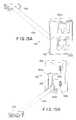
- FIGS. 3 and 4are perspective views of one embodiment of the physical structure of the field controller depicted in FIG. 2;
- FIG. 5is a perspective view of a head unit attached to a side cover
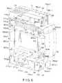
- FIG. 6is a perspective view of a head unit coupled to an expansion module and a side cover;
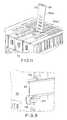
- FIG. 7is a perspective view of a side cover with two expansion modules attached, and a head unit positioned to be attached to one of the expansion units;
- FIG. 8is a rear perspective view of a left side cover
- FIG. 9is a detail of a mounting mechanism
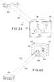
- FIGS. 10A and 10Bare perspective views of one type of internal dongle
- FIGS. 11is a detail of a top portion of field controller 12 (F);
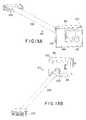
- FIGS. 12-15are perspective views of different embodiments of internal dongles
- FIGS. 16A and 16Bare perspective views of a pass-through dongle
- FIG. 17is a conceptual drawing of a ground bus in a field controller according to the invention.
- FIG. 1is a functional block diagram of a distributed control system 10 which includes a field controller constructed in accordance with the invention.
- the distributed control system 10may be used, for example, in a number of commercial, industrial and home applications, in particular to monitor and control a variety of diverse types of operations.
- the distributed control system 10may, for example, control various machines and robots to facilitate manufacture of those components that are manufactured on site, and transfer of the components from inventory to assembly locations where they are assembled into the final product.
- the distributed control system 10will also receive status information regarding the operational status of the various machines controlled by the system, as well as, for example, the inventory of the various components which may be used in manufacture of the end product and the assembly line, which status information the system 10 may use in controlling the rate of component manufacture and product assembly.
- the distributed control system 10may control the rates of flow of chemicals within the operation, as well as reaction parameters such as temperatures, pressures and the like of the chemical reaction chambers, with the control being exercised in response to corresponding status information the system 10 receives from the controlled components of the processing plant.
- the distributed control system 10may monitor and control a variety of environmental factors, including, for example, heating, air conditioning, ventilation, energy consumption and supply, and so forth.
- the distributed control system 10 depicted in FIG. 1provides for distributed control in a commercial, industrial or home environment operation.
- the distributed control system 10includes an area controller 11 and one or more field controllers 12 (A) through 12 (C) (generally identified by reference numeral 12 (C), which may be conveniently interconnected by a network 13 or other communications arrangement.
- field controllers 12 (A) through 12 (C)generally identified by reference numeral 12 (C)
- the area controller 11maintains overall control of the industrial operation under control, or a portion thereof, thereby maintaining overall control of the manufacturing process.
- each field controller 12 (F)will receive status information preferably from sensors (also not shown) in its assigned portion of the plant which indicate their status in the process under control.
- the field controller 12 (F)may, in response to the status information it receives from the sensors connected thereto, control the machines to perform selected operations as determined by their programming.
- the field controller 12 (F)may notify the area controller 11 if the status information indicates that an operation in its area is outside of a selected operational range, and the area controller 11 may initiate corrective procedures in connection therewith.
- FIG. 2depicts a functional block diagram of a field controller 12 (F) useful in the distributed control system 10 .
- the field controller 12 (F)comprises a plurality of modules, including a processor module 20 and one or more expansion modules 21 ( 1 ) through 21 (N) (generally identified by reference numeral 21 ( e )) whose electrical features are depicted in FIG. 2 .
- the modules 20 and 21 ( e )each have external connections which are positioned and configured to enable them to be connected together in a relatively compact manner.
- the modules 20 and 21 ( e )provide external interfaces to control devices in the factory environment.
- the entire field controllercomprising the processor module 20 , one or more expansion modules 21 ( e ), along with power supply and input/output devices which may be connected thereto (not shown) provides a very compact yet computationally powerful and easily maintainable package, which is convenient and quite useful in an industrial environment.
- the processor module 20comprises a processor submodule 22 and a local communications submodule 23 .
- the processor submodule 22includes a central processor unit (CPU) 24 , a read only memory (ROM) 25 and a random access main memory 26 , all of which are connected to a bus segment, such as, for example, ISA bus 27 , and may also include other components as described below.
- the CPU 24is preferably in the form of a microprocessor.
- the ROM 25provides non-volatile storage which may be used for, for example, a BIOS (basic input/output system) portion of the operating system program that controls the CPU 24 , and may also provide storage for certain other fixed operating information.
- BIOSbasic input/output system
- the main memory 26which may consist of one or more conventional DRAM (dynamic random-access memory) chips, provides storage for programs and data which may be down-loaded be the area controller 11 to enable the field controller 12 (F) to operate, data received from the controlled devices and sensors controlled by the field controller 12 (F), information processed by the CPU 24 , and status information which may be retained for transmission to the area controller.
- DRAMdynamic random-access memory
- processor submodule 22may include one or more external communication ports, such as, for example, serial ports 30 . Ports 30 may be used, for example, for facilitating communications with the area controller 11 .
- Processor submodulealso includes devices such as light emitting diodes (LED) 31 for providing visual status indications, and devices for receiving local control input, such as a reset signal provided by a reset button (RST) 32 .
- Processor submodule 22may also include devices such as speakers (not shown) for generating audible alarm or status indications. All of these elements are indicated as being connected to ISA bus 27 over a system interface bus 33 .
- bus 27conforms to the ISA bus specification, it will be appreciated that other types of busses may be used for a bus segment.
- the bus segmentwill be in the form of a “multi-drop” bus, that is, it will facilitate the interconnection of more than two devices to facilitate the transfer of data and status information.
- the bus segmentwill preferably provide an interrupt facility, by which the central processor unit 24 can receive interrupt requests from other devices that are connected to the bus to notify it of conditions that may occur on an asynchronous or non-periodic basis which require servicing by the central processor unit 24 , as will be described below.
- the processor submodule 22in one embodiment is preferably in the form of a single module having a form factor defined by the PCMCIA (Personal Computer Memory Card International Association) standard, with dimensions generally 3.375 inches long by 2.125 inches wide, by 0.25 inch deep, and having an ISA bus interface preferably along one of its long edges.
- PCMCIAPersonal Computer Memory Card International Association
- a suitable processor sub-module 22is currently sold by S-MOS Corporation as a model CARDIOTM 486 processor module, which provides the above-identified components and including an 80486-class microprocessor as the central processor unit.
- the local communications sub-module 23also includes a bus segment 40 and a plurality of PCMCIA interfaces 41 ( 1 ) through 41 (P) (generally identified by reference numeral 41 ( p )), which are interconnected by an interface controller chip I/F 42 .
- the bus segment 40 of the local communications submodule 23is logically similar to the bus segment 27 of the processor sub-module 22 .
- the local communication sub-module's bus segment 40will also conform to the ISA bus specification.
- the local communications sub-module's bus segment 40connects to the processor sub-module's bus segment 27 through a downstream connector 43 .
- the interface controller chip I/F 42provides a connection from the bus segment 40 to the PCMCIA interfaces 41 ( p ).
- Each PCMCIA interfacein turn, provides a connection to a PCMCIA device, that is, a device which conforms to the electrical interface defined by the PCMCIA specification identified above.
- the PCMCIA specificationdefines, in addition to the PCMCIA form factor described above, an electrical interface which is essentially a point-to-point bus, that is, a bus which interconnects only two devices.
- Each PCMCIA interface 41 ( p )includes an interface connector 44 ( p ) which connects to the interface controller chip 42 , an interface card 45 ( p ), and an external interface 46 ( p ) which provides an interface to a controlled device (not shown) which may be located in the industrial environment, as described above.
- the interface card 45 ( p )is preferably constructed in the PCMCIA form-factor as described above, and provides circuitry which converts between PCMCIA signals provided by the interface controller chip 42 and signals transmitted to and received from the controlled device or sensor connected to the card 45 ( p ). It will be appreciated that the particular circuitry provided in each interface card 45 ( p ) will generally depend on the particular controlled device or sensor to which the card 45 ( p ) is connected.
- the processor module 20provides an interface to two controlled devices through the local communications sub-module 23 .
- one or more expansion modules 21 ( e )may be connected to the processor module 20 .
- the local communications sub-module 23in addition to providing a connector 43 to the processor module 22 , also provides an upstream connector 47 , which may be connected to an expansion module 21 ( 1 ), as shown in FIG. 2 .
- Each expansion module 21 ( e )the physical structure of which will be described below, is electrically and logically similar to the local communications sub-module 23 . That is, it is provided with a downstream connector 50 , a bus segment 51 , an upstream connector 52 , an interface controller chip 53 . and a plurality of PCMCIA interfaces 54 ( 1 ) through 54 (Pe) (generally identified by reference numeral 54 (P)) which include an interface connector 55 ( p ) which connects to the interface controller chip 53 , an interface card 56 ( p ), and an external interface 57 ( p ) which provides an interface to a controlled device (not shown) which may be located in the industrial environment, as described above.
- PCMCIA interfaces 54 ( 1 ) through 54 (Pe)(generally identified by reference numeral 54 (P)) which include an interface connector 55 ( p ) which connects to the interface controller chip 53 , an interface card 56 ( p ), and an external interface 57 ( p ) which provides an interface to
- the maximum number of PCMCIA interfaces 54 ( Pe ) that may be connected in an expansion controllerwhich also corresponds to the number of PCMCIA interfaces 41 ( p ) which can be connected in the processor sub-module 20 , is two, but it will be appreciated that an expansion module 21 ( e ) may provide more or fewer interfaces than the processor module 20 .
- the downstream connector 50 of the first expansion module 21 ( 1 )connects to the external connector 47 of the processor module 20 , to connect the bus segment 51 of the first expansion module 21 ( 1 ) to the bus segment 40 of the local communications sub-module 23 , and thus to facilitate the transfer of signals from the processor sub-module 22 to the first expansion module 21 ( 1 ).
- the bus segment 51couples the signals from the downstream connector 50 to the upstream connector 52 for transfer to a further expansion module 21 ( 2 ) through its downstream connector 50 ( 2 ), if one is provided in the field controller 12 (F).
- the interface controller chip 53couples signals between the bus segment 51 and the PCMCIA interfaces 54 ( Pe ) which are provided in the first expansion module 21 ( 1 ).
- the expansion modules 21 ( e )are all electrically similar (and are similar to the local communications sub-module 23 as described above). Accordingly, for each expansion module 21 ( e ) after the first, the respective downstream connector 50 ( e ) will connect to the upstream connector 52 ( e ⁇ 1) of the preceding expansion module 21 ( e ⁇ 1) in the series, and the upstream connector 52 ( e ) will connect to the downstream connector 50 ( e+ 1) of the next expansion module 21 ( e+ 1) in the series, with the module's bus segment 51 ( e ) coupling signals between the downstream connector 50 ( e ) and the upstream connector 52 ( e ).
- the interface controller chip 53 ( e ) in the respective expansion module 21 ( e )connects to the bus segment 51 and the PCMCIA interfaces 54 ( Pe ) allowing the expansion module 21 ( e ) to connect to a number of controlled devices over respective PCMCIA interfaces (not shown).
- the bus segments 27 . . . 40 . . . 51 ( e )interconnected by respective connectors 43 , 47 , 50 ( 1 ), 52 ( 1 ), 50 ( e ), 52 ( e ), provide a continuous path for carrying data and control signals from the central processor unit CPU 24 of the processor sub-module 22 to the respective local communications sub-module 23 and expansion module 21 ( e ).
- the central processor unit CPU 24is able to control the controlled device(s) through the PCMCIA interfaces 45 ( p ) (as in the case of a controlled device connected to the local communications sub-module 23 ) or 54 ( Pe ) (as in the case of a controlled device connected to an expansion module 21 ( e ).
- the field controller 12 (F)further includes a module selection arrangement, which is described in detail in co-pending co-owned application Ser. No. 08/560,167, filed Nov. 20, 1995, the entire disclosure of which is included herein by reference. It will suffice to mention here that the processor sub-module 22 can select which of the local communications sub-module 23 or expansion module 21 ( e ) is to receive signals transmitted by it (that is, the processor sub-module 22 ) on the respective bus segments 27 . . . 40 . . . 51 ( e ), or which of the local communications sub-module 23 or expansion module 21 ( e ) is to transmit signals to it (that is, the processor sub-module 22 ) onto the respective bus segments 27 . . . 40 . . . 51 ( e ).
- the processor submodule 22includes an addressing circuit that automatically assigns unique addresses to the PCMCIA cards, such that individual addressing of the PCMCIA cards is unnecessary.
- the field controller 12 (F)provides an architecture which may be conveniently implemented in a compact package which can be readily installed and maintained in a factory environment.
- the field controller of the described embodimentmay be mounted on, for example, a vertical support such as a wall, with the processor module 20 (or, as it will be referred to below, the “head unit”) and each expansion module 21 ( e ) being generally configured so that, when an expansion module is added to the field controller 12 (F), it will be connected to the head unit 20 or to previously-provided expansion modules so as to extend the field controller 12 (F) in a direction which is generally parallel to a plane of the vertical support.
- a vertical supportsuch as a wall
- the processor module 20or, as it will be referred to below, the “head unit”
- each expansion module 21 ( e )being generally configured so that, when an expansion module is added to the field controller 12 (F), it will be connected to the head unit 20 or to previously-provided expansion modules so as to extend the field controller 12 (F) in a direction which
- 08/560,167may also be mounted on a vertical support, but the processor module and expansion modules are generally configured so that, when an expansion module is added to the field controller, it will be connected to the processor module or to previously-provided expansion modules so as to extend the field controller 12 (F) in a direction which is generally transverse to a plane of the vertical support.
- a field controller 12 (F)includes at least a head unit 20 and may also include one or more expansion modules 21 ( e ). It will be appreciated that the head unit 20 includes an implementation of the circuit elements of the processor module 20 described above in connection with the schematic diagram in FIG. 2, and the expansion modules 21 ( e ) each include an implementation of the circuit elements of an expansion module 21 ( e ) described above in connection with the schematic diagram in FIG. 2 .
- the field controller 12 (F)includes a segmented chassis having a segmented housing 60 . Housing 60 has a rear mounting bracket 62 for mounting the field controller 12 (F) onto a DIN rail 64 , which may be attached to a wall or free-standing.
- the housing 60includes a left side cover 66 and a right side cover 68 .
- Right side cover 68includes a hinged door 69 which provides access to electrical components inside the field controller 12 (F) as will be described below.
- Sandwiched in between side covers 66 , 68is the head unit 20 and expansion modules 21 ( 1 ), 21 ( 2 ) and 21 ( 3 ), each of which have respective housings.
- Head unit 20includes a head unit housing 70 that extends around top, rear and bottom sides, and a removable front cover 72 that provides access to the inside of head unit housing 70 when removed. Front cover 72 snaps in and out of engagement with connective elements within head unit housing 70 as will be described below.
- Head unit housing 70also includes a top lid 71 which is hinged at its rear end to a primary portion of head unit housing 70 to allow access to the interior of housing 70 from the top when opened.
- a similarly configured bottom lid 73(see FIG. 5) is hinged on a bottom side of housing 70 to allow access to the interior of housing 70 from the bottom when opened.
- Expansion modules 21 ( 1 )- 21 ( 3 )have identically configured expansion housings 74 ( 1 )- 74 ( 3 ), respectively (generally identified by 74 ( e )), which extend around top, rear and bottom sides of expansion modules 21 ( e ).
- Each of the expansion housings 74 ( e )include a removable expansion front cover 76 ( 1 )- 76 ( 3 ) (generally identified by 76 ( e )) which is configured identically to processor front cover 72 .
- Each expansion front cover 76 ( e )snaps in and out of engagement with connective elements within the respective expansion housing 74 as will be described below. Removing an expansion front cover 76 ( e ) provides access to the inside of its expansion housing 74 ( e ).
- Each expansion housing 76 ( e )also includes a hinged top lid 78 ( e ) and a similarly configured hinged bottom lid 75 ( e ) (see FIG. 6 ).
- the top and bottom lids and 75 ( a ) of the expansion housings 74 ( e )provide access to the interiors of the individual expansion housings 74 ( e ) from the top and bottom ends.
- All housing components 66 , 68 , 70 , 71 , 72 , 74 ( e ), 76 ( e ), 78 ( e ) and 75 ( a )are made of a molded thermoplastic, such as, for example Norel 190 , which is supplied by General Electric Corp.
- Each of the head unit housing 70 and expansion unit housings 74 ( e )provide a pair of recesses in which an I/O connector device 79 may be inserted.
- I/O connector device 79A variety of different I/O devices will be described in detail below.
- Each respective housing 70 , 74 ( e )provides a first recess at a top end between the top of its front cover 72 , 76 ( e ) and its respective top lid 71 , 78 ( e ).
- a second recessis provided between the bottom of the front cover 72 , 76 ( e ) and its respective bottom lid 73 , 75 ( e ) (see FIGS. 5 and 6 ).
- Head unit 20includes a head board 80 positioned inside head unit housing 70 .
- the processor submodule 22is mounted on the right side of the head board 80 .
- An SMOS card embodying the processor submodule 22is shown in shadow with broken lines mounted in a connector 84 .
- SMOS card 22is mounted in a plane parallel to the plane defined by headboard 80 .
- Components mounted below connector 84include the reset switch 32 which is accessible through an aperture 86 provided in right side cover 68 (see FIG. 3 ).
- Serial communication ports 30are accessible through door 69 (see FIG. 3 ).
- a block 88 for connecting power, a transformer 82 , and two light pipes 58 which bring light from LEDs 31 to an LED display 59 at the front of right side cover 68(see also FIG. 3 ).
- An RS-232 connector 61is also provided. Notice also, alignment pins 77 ′ which help during assembly to align with apertures (not shown) formed in the inside of right side cover 68 .
- Head unit front cover 72includes connective brackets 90 which snap into and out of engagement with two front stand-offs 92 .
- Head board 80is held in place by the two front and two rear stand-offs 92 , which couple on one side of head board 80 and on the other side of head board 80 to one of the left side cover 66 and an expansion module 21 ( e ) (neither shown in FIG. 5 ).
- Right side cover 68connects to the four stand-offs 92 with four screws (see FIG. 3) that screw into the right-most ends of stand-offs 92 .
- Stand-offs 92are held in place with respect to head unit housing 70 at least in part by ground straps 83 which form portions of a head unit ground bus 85 .
- Head unit housing 70is also held in position with respect to an adjacent expansion module 21 ( e ) or left side cover 66 by receiving alignment pins 77 ′( e ) (see FIGS. 7 and 10) formed on the adjacent expansion module 21 ( e ) or cover 66 into alignment apertures 77 .
- Head unit housing 70also forms alignment pins 77 ′ which fit into apertures 77 ( e ) formed in an adjacent expansion housing 74 ( e ) or the left side cover 66 (see FIGS. 7 and 10 ).
- Ground bus 85is electrically coupled to DIN rail 64 through the stand-offs 92 , which connect to a ground bus in the left side cover 66 that itself connects directly to the DIN rail 64 , as will be described below.
- Two peripheral connectors 94 ( 1 ) and 94 ( 2 )are mounted in parallel, side-by-side arrangement on another side of head board 80 .
- Each of connectors 94 ( 1 ) and 94 ( 2 )are adapted to receive a PCMCIA card 95 , one of which can be seen in dashed line shadow in FIG. 5 .
- Also mounted in parallel alignment with head board 80is an upstream expansion connector 47 for electrically coupling with a mating upstream expansion connector 50 on an expansion module 21 ( e ) (see FIG. 7 ).
- expansion module 21 ( e )is attached to the head unit 20 .
- Expansion module 21 ( e )includes an expansion board, generally identified by 81 ( e ), in the expansion housing 74 ( e ).
- the expansion unit 20 ( e ) illustrated in FIG. 6is mechanically coupled to the head unit 20 between the head unit 20 and the left side cover 66 , although there may be one or more other expansion modules 21 ( e ) between the left side cover 66 and the expansion module located adjacent the head unit 20 , as illustrated in FIGS. 3 and 4.
- expansion modules 21 ( e )are narrow units which are oriented orthogonal to the mounting plane of the field controller 12 (F).
- Expansion board 81 ( e )is held in place by stand-offs, generally identified by 92 ( e ), which connect to stand-offs 92 in head unit 20 in the configuration illustrated in FIG. 6 .
- Expansion housing front cover 76 ( e )has brackets 90 ( e ) which snap in and out of engagement with front stand-offs 92 ( e ).
- Expansion housing 74 ( e )is held in place relative to expansion board 81 ( e ) at least in part by two ground straps (only one visible in FIG.
- ground bus 85 ( e )connects to ground at the DIN rail 64 via the stand-offs 92 ( e ), as does the ground bus 85 in the head unit 22 .
- Each expansion board 81 ( e )includes a pair of peripheral connectors 93 (e 1 ) and 93 (e 2 ) (generally identified by 93 ( e )) positioned on a side facing away from the head unit 20 . Either or both of peripheral connectors 93 ( e ) may receive a PCMCIA card 95 ( e ). Peripheral connectors 93 ( e ) and any attached PCMCIA cards 95 ( e ) are aligned side-by-side in parallel with expansion unit board 81 ( e ). Each expansion board 81 ( e ) also includes an upstream expansion connector 52 on the same side as the peripheral connectors 93 ( e ).
- FIG. 7shows two expansion modules 21 ( 1 ) and 21 ( 2 ) already connected to the left side cover 66 and the head unit 20 aligned to be connected to the right most expansion module 21 ( 2 ).
- a downstream expansion connector 50is positioned on the side of the expansion board 81 ( e ) nearest the head unit 20 .
- Each upstream expansion connector 52is adapted to connect to a downstream expansion connector 50 on another expansion board 81 ( e ) in a different expansion module.
- the downstream expansion connector 50 on the right-most expansion module 21 ( 2 )connects to the upstream expansion connector 47 on the head board 80 .
- the upstream expansion connector on the left-most expansion module 21 ( 1 )does not connect to anything because it is adjacent the left side cover 66 .
- the expansion modules 21 ( 1 ), 21 ( 2 ) and the head unit 20are also coupled together by the stand-offs 92 , 92 ( e ).
- Stand-offs 92 and 92 ( e )each include a threaded left end 97 that screws into the right end of the next left-most stand-off 92 ( e ).
- Standoffs 92 ( e ) of expansion module 21 ( 1 )screw into threaded fittings in left side cover 66 .
- the connected stand-offs 92 , 92 ( e ), which are made of a conductive metal,provide a ground bus that runs through the chassis and electrically couples to a ground line on each expansion board 81 and the head board 80 .
- each of the side covers 66 , 68includes a molded top hook 109 which is adapted to fit over the top edge of the DIN rail 64 .
- top hook 109is placed over the DIN rail 64 , a quarter-turn pawl 107 which extends through bracket 105 is turned upwards to engage the lower end of the DIN rail 64 . Tightening the pawl 107 presses the spring-like portion 101 of the ground strip 97 into electrical engagement with the DIN rail 64 , thereby providing a ground path for the field controller 12 (F).
- I/O connective devices 79 ( 1 ) and 79 ( 2 )are shown installed into head unit 20 .
- I/O devices 79 ( 1 ) and 79 ( 2 )are particularly configured for use with the described embodiment of field controller 12 (F).
- Ffield controller 12
- Donglesusually refer to connecting cables that include a connector at each end and that also include some signal conditioning circuitry.
- I/O devices internal donglesbecause they are structured to be mounted to a device such that their front face forms a portion of the housing of the device and such that their cabling and circuitry are located within the chassis.
- each internal dongle 79includes an injection molded, electrically insulating body 96 having connective structure arranged to removably attach the body 96 to the housing 60 of field controller 12 (F).
- the connective structureincludes a ground socket 98 adapted to connect to a fast-on type ground connector 100 mounted within housing 60 .
- a circuit assemblyincludes an external connector 102 on the body 96 for electrically connecting to a cable (not shown) from a field controllable device.
- the exterior connector 102is of a type for connecting to an Allen-Bradley device.
- a dongle circuitwhich includes connective wiring and may also include passive circuitry 103 ( a ) and active circuitry 103 ( b ) for signal conditioning, is electrically coupled to the external connector 102 through the body 96 .
- Some elements of the dongle circuitare located on a circuit board 104 which is mounted integrally on a rear end of the dongle body 96 .
- An electronic cable 106has one end electrically coupled to the dongle circuit on the circuit board 104 , and its other end terminating with a connector 108 adapted to connect to an electronic component within the field controller housing 60 .
- connector 108is adapted for connecting to a mating connector 110 on a PCMCIA card 95 .
- a cable strap 112helps to relieve mechanical stress at the electrical connections between the circuit board 104 and the cable wires.
- a rectangular-shaped forward facing front surface 114 of the dongle body 96is structured to form, with the head unit housing 70 or an expansion module housing 74 ( e ), a continuous outer surface of the housing 60 when the dongle body 96 is attached to the housing.
- the dongle body 96includes a ground socket 98 which connects to a grounded fast-on type connector 100 within head unit housing 70 or expansion unit housing 74 ( e ).
- Internal dongles 79also include other connective structures for assuring a secure mechanical connection with housing 70 or 74 ( e ).
- One end of the body 96includes a lip 116 that is hooked in a rearward direction to overlap the edge of a plate 118 within the housing 70 or 74 ( e ).
- a surface of the body 96 located approximately opposite from the lip 116forms a groove 120 that is adapted to engage with a bead 122 extending inward from a forward edge of each of the hinged lids 71 , 73 , 75 ( e ), 78 ( e ) when the lid is closed.
- FIG. 11A detail view of a top lid 78 ( e ) is illustrated in FIG. 11.
- a dongle 79 in, for example, expansion housing 74 ( e )can be accessed with lid 78 ( e ) in a raised position.
- One end of lid 78 ( e )is articulated at a rear end from a main portion of expansion housing 74 ( e ) by hinge 124 .
- the bead 122 at the forward end of raised lid 78 ( e )is clearly shown in the drawing.
- a small tab 126extending laterally from the forward end of the lid 78 ( e ) near bead 122 .
- Tab 126snaps into and out of engagement with structure 128 formed in an adjacent module 21 ( e ) or head unit 20 .
- Dongles 79 ( 1 ) and 79 ( 2 )are respectively installed in top and bottom recesses of head unit housing 70 .
- Dongle cables 106(shown in broken line shadow) are brought and rearward and bent around forward inside housing 70 . Cables 106 are then brought around in front of front stand-offs 92 , and brought forward again to couple their connectors 108 to mating connectors 110 on the PCMCIA cards 95 .
- Front cover 72is bowed outward to provide extra space to bring cables 106 around in front of PCMCIA cards 95 .
- a similar cable arrangementis used in the expansion modules 21 ( e ). (In other figures, the dongle cables have been omitted to simplify the illustration.)
- FIG. 17is a conceptual drawing illustrating features of the ground bus for a field controller 12 (F) with four expansion modules 21 ( e ), however, only the expansion board ( 81 e ) of one is shown.
- Faston-type ground plugs 100 , ground straps 85 and 83 ( e ), stand-offs 92 and 92 ( e ), and ground strip 97 on side cover 66are shown. It can be seen that in between each pair of connected stand-offs ( 92 or 92 ( e ) are one ground strap ( 85 or 83 ( e )) and one circuit board (either 80 or 81 ( e )).
- an internal dongle 130having an external connector 132 on its front face for making a connection to an ethernet device.
- the dongle circuitincludes an LED 134 to indicate an active status. Structurally, it is very similar to the Allen-Bradley type dongle 79 illustrated in FIGS. 10A and 10B, having a molded body 96 , a fast-on type ground socket 98 on a rear side of the body 96 , a circuit board 104 , a cable 106 , and a connector 108 for a PCMCIA card at the free end of the cable 106 .
- dongle 130includes active and passive circuitry.
- Dongle 140has an ethernet connector 142 accessible on its front face 144 .
- Dongle 150includes an exterior connector 152 for coupling to a controlled device, a ribbon cable 156 and an RS-232 connector 158 at the free end of the cable 156 .
- Dongle 150may be used in the head unit 20 to connect to the RS-232 connector 61 provided on the head board 80 .
- Dongle 150includes a transceiver.
- Double dongle 160includes a body 168 which is approximately twice the size of other dongle bodies to provide space for two exterior connectors 162 a and 162 b , which connect to two different external cables.
- Each of connectors 162 a , 162 bcouple through body 168 to circuitry that is provided on a respective one of circuit boards 164 a , 164 b .
- the respective circuitsare coupled by wires 166 .
- a single cable 106connects between board 154 b and connector 168 .
- Pass-through dongle 170is not a dongle in the usual sense, but is used to pass a cable through housing 60 .
- Pass-through dongle 170is formed of a single piece of an insulative injection molded material that is fairly rigid but has a degree of resilience and flexibility, such as, for example, hard rubber.
- Pass-through dongle 170includes a substantially rectilinear, solid body 172 , including front and rear ends 174 , 176 , four sides and a groove 178 extending from a side surface 179 into the body 172 from the front 174 to the rear end 176 .
- the front end 174forms a part of the housing 60 exterior when installed.
- pass-through dongle 170includes connective structure adapted to removably connect the body 172 to the housing 60 .
- An aperture 180forms a socket to receive a faston-type ground plug 100 .
- Lip 116 and groove 120are structured as described above with reference to dongle 79 .
- Front end 174forms a sheet 182 of nonconductive material that extends across the groove 178 .
- the sheet 182provides a circular opening 184 sized to allow the cable to pass therethrough.
- a slit 186extends from the side surface 179 to the circular opening 184 .
- the sheet 182being integrally formed with the body 172 , is fabricated of a resilient material structured to allow the cable to be inserted through the slit 186 and into the circular opening 184 such that the cable extends along the groove 178 and extends into the housing 60 from the rear end 176 of the body 172 when the body is connected to the housing 60 .
- the rear end 176 of the body 172forms a shelf or plate 188 adjacent the groove 178 .
- Plate 188has two apertures 190 , 192 adapted to secure the cable with a cable tie or the like on either side of the cable.
- any bus including bus segments 27 , 40 , and 51can be a multi-drop bus so that the PCMCIA interface cards for the various controlled devices can be connected anywhere along the bus.
- new field controller 12 (F)has been described as operating in a distributed control system 10 under control of an area controller 11 , it will be appreciated that, depending on the particular application, area controller may not be necessary and the field controller may operate independently. In addition, it will be appreciated that a variety of devices may be controlled by a field controller as described herein, including other field controllers.
- the internal dongles described aboveare particularly adapted to be used in the described field controller 12 (F).
- Other physical designs for internal dongles adapted to fit other electronic devicesare also within the scope of the invention.
- Internal dongles adapted for making connections to external devices other than those described aboveare also within the spirit and scope of the invention.
Landscapes
- Engineering & Computer Science (AREA)
- Physics & Mathematics (AREA)
- General Physics & Mathematics (AREA)
- Automation & Control Theory (AREA)
- General Engineering & Computer Science (AREA)
- Manufacturing & Machinery (AREA)
- Quality & Reliability (AREA)
- Programmable Controllers (AREA)
- Casings For Electric Apparatus (AREA)
Abstract
Description
Claims (63)
Priority Applications (1)
| Application Number | Priority Date | Filing Date | Title |
|---|---|---|---|
| US09/591,730US6496892B1 (en) | 1995-10-10 | 2000-06-12 | Control device with PCMCIA card for communications with field device |
Applications Claiming Priority (5)
| Application Number | Priority Date | Filing Date | Title |
|---|---|---|---|
| US527995P | 1995-10-10 | 1995-10-10 | |
| US08/560,167US6076124A (en) | 1995-10-10 | 1995-11-20 | Distributed control system including a compact easily-extensible and serviceable field controller |
| US08/725,740US6033257A (en) | 1995-11-20 | 1996-10-04 | I/O connector module for a field controller in a distributed control system |
| US09/317,403US6183289B1 (en) | 1995-11-20 | 1999-05-24 | I/O connector module for a field controller in a distributed control system |
| US09/591,730US6496892B1 (en) | 1995-10-10 | 2000-06-12 | Control device with PCMCIA card for communications with field device |
Related Parent Applications (1)
| Application Number | Title | Priority Date | Filing Date |
|---|---|---|---|
| US09/317,403ContinuationUS6183289B1 (en) | 1995-10-10 | 1999-05-24 | I/O connector module for a field controller in a distributed control system |
Publications (1)
| Publication Number | Publication Date |
|---|---|
| US6496892B1true US6496892B1 (en) | 2002-12-17 |
Family
ID=27072267
Family Applications (3)
| Application Number | Title | Priority Date | Filing Date |
|---|---|---|---|
| US08/725,740Expired - LifetimeUS6033257A (en) | 1995-10-10 | 1996-10-04 | I/O connector module for a field controller in a distributed control system |
| US09/317,403Expired - LifetimeUS6183289B1 (en) | 1995-10-10 | 1999-05-24 | I/O connector module for a field controller in a distributed control system |
| US09/591,730Expired - LifetimeUS6496892B1 (en) | 1995-10-10 | 2000-06-12 | Control device with PCMCIA card for communications with field device |
Family Applications Before (2)
| Application Number | Title | Priority Date | Filing Date |
|---|---|---|---|
| US08/725,740Expired - LifetimeUS6033257A (en) | 1995-10-10 | 1996-10-04 | I/O connector module for a field controller in a distributed control system |
| US09/317,403Expired - LifetimeUS6183289B1 (en) | 1995-10-10 | 1999-05-24 | I/O connector module for a field controller in a distributed control system |
Country Status (3)
| Country | Link |
|---|---|
| US (3) | US6033257A (en) |
| EP (1) | EP0862756A4 (en) |
| WO (1) | WO1997019397A1 (en) |
Cited By (25)
| Publication number | Priority date | Publication date | Assignee | Title |
|---|---|---|---|---|
| US20040122738A1 (en)* | 1993-01-26 | 2004-06-24 | Logic Controls, Inc. | Point-of-sale system and distributed computer network for same |
| WO2005001699A3 (en)* | 2003-06-26 | 2005-02-10 | Endress & Hauser Process Solut | Field bus distribution unit |
| WO2004061535A3 (en)* | 2002-12-23 | 2005-04-14 | Siemens Energy & Automat | Device, system, and method for the automatic configuration of a network communications device |
| US20050083197A1 (en)* | 2003-10-15 | 2005-04-21 | Glenn Gregory M. | Method and apparatus for monitoring conditions |
| US6934788B2 (en)* | 1999-07-08 | 2005-08-23 | Intel Corporation | Port expansion peripheral module system |
| US6968160B2 (en)* | 2000-01-15 | 2005-11-22 | Koninklijke Philips Electronics N.V. | Telemetry system with transmitter holding position assignment |
| US20080022017A1 (en)* | 2006-07-07 | 2008-01-24 | Logic Controls, Inc. | Hybrid industrial networked computer system |
| US20080235416A1 (en)* | 2007-03-19 | 2008-09-25 | Hon Hai Precision Industry Co., Ltd. | Uart interface communication circuit |
| US20080276031A1 (en)* | 2007-02-07 | 2008-11-06 | General Dynamics Advanced Information Systems, Inc. | Method and apparatus for a federation control plane in an orthogonal system |
| US7720944B2 (en) | 1996-08-20 | 2010-05-18 | Invensys Systems, Inc. | Process control system with networked digital data processors and a virtual machine environment |
| US20100144542A1 (en)* | 2005-12-07 | 2010-06-10 | Affymetrix, Inc | Methods for high throughput genotyping |
| US7761923B2 (en) | 2004-03-01 | 2010-07-20 | Invensys Systems, Inc. | Process control methods and apparatus for intrusion detection, protection and network hardening |
| US7860857B2 (en) | 2006-03-30 | 2010-12-28 | Invensys Systems, Inc. | Digital data processing apparatus and methods for improving plant performance |
| US7890927B2 (en) | 1999-05-17 | 2011-02-15 | Invensys Systems, Inc. | Apparatus and method for configuring and editing a control system with live data |
| US20110288657A1 (en)* | 2008-11-21 | 2011-11-24 | Sirti S.P.A. | Method and system for the protection of an electric line for railway signals |
| US8090452B2 (en) | 1999-06-11 | 2012-01-03 | Invensys Systems, Inc. | Methods and apparatus for control using control devices that provide a virtual machine environment and that communicate via an IP network |
| US8127060B2 (en) | 2009-05-29 | 2012-02-28 | Invensys Systems, Inc | Methods and apparatus for control configuration with control objects that are fieldbus protocol-aware |
| US20120155004A1 (en)* | 2010-12-17 | 2012-06-21 | Sony Corporation | Information processing device |
| US8368640B2 (en) | 1999-05-17 | 2013-02-05 | Invensys Systems, Inc. | Process control configuration system with connection validation and configuration |
| US8463964B2 (en) | 2009-05-29 | 2013-06-11 | Invensys Systems, Inc. | Methods and apparatus for control configuration with enhanced change-tracking |
| US8594814B2 (en) | 2008-06-20 | 2013-11-26 | Invensys Systems, Inc. | Systems and methods for immersive interaction with actual and/or simulated facilities for process, environmental and industrial control |
| US20190278341A1 (en)* | 2018-03-09 | 2019-09-12 | Dinkle Enterprise Co., Ltd. | System Comprising Multiple Functional Modules and Addressing Method for Functional Modules thereof |
| US10729031B1 (en)* | 2019-04-15 | 2020-07-28 | Dinkle Enterprise Co., Ltd. | Control system comprising multiple functional modules and addressing method for functional modules thereof |
| USRE48365E1 (en) | 2006-12-19 | 2020-12-22 | Mobile Motherboard Inc. | Mobile motherboard |
| LU101844B1 (en)* | 2020-06-08 | 2021-12-08 | Phoenix Contact Gmbh & Co | Housing for an electrotechnical device |
Families Citing this family (84)
| Publication number | Priority date | Publication date | Assignee | Title |
|---|---|---|---|---|
| US6033257A (en)* | 1995-11-20 | 2000-03-07 | The Foxboro Company | I/O connector module for a field controller in a distributed control system |
| US6076124A (en) | 1995-10-10 | 2000-06-13 | The Foxboro Company | Distributed control system including a compact easily-extensible and serviceable field controller |
| US5909586A (en)* | 1996-11-06 | 1999-06-01 | The Foxboro Company | Methods and systems for interfacing with an interface powered I/O device |
| US6848045B2 (en)* | 1999-01-15 | 2005-01-25 | Rainbow Technologies, Inc. | Integrated USB connector for personal token |
| DE19964156B4 (en)* | 1999-01-25 | 2004-07-15 | Weidmüller Interface Gmbh & Co. | Electric device |
| US7206646B2 (en) | 1999-02-22 | 2007-04-17 | Fisher-Rosemount Systems, Inc. | Method and apparatus for performing a function in a plant using process performance monitoring with process equipment monitoring and control |
| US7562135B2 (en) | 2000-05-23 | 2009-07-14 | Fisher-Rosemount Systems, Inc. | Enhanced fieldbus device alerts in a process control system |
| US8044793B2 (en)* | 2001-03-01 | 2011-10-25 | Fisher-Rosemount Systems, Inc. | Integrated device alerts in a process control system |
| US7346404B2 (en) | 2001-03-01 | 2008-03-18 | Fisher-Rosemount Systems, Inc. | Data sharing in a process plant |
| US6975219B2 (en)* | 2001-03-01 | 2005-12-13 | Fisher-Rosemount Systems, Inc. | Enhanced hart device alerts in a process control system |
| DE59907873D1 (en)* | 1999-10-15 | 2004-01-08 | Flowtec Ag | Programmable field measuring device |
| US6697684B2 (en) | 2000-02-15 | 2004-02-24 | Thomas Gillen | Programmable field measuring instrument |
| JP4524872B2 (en)* | 2000-07-07 | 2010-08-18 | Smc株式会社 | Signal input / output device |
| AT501651B1 (en)* | 2000-09-27 | 2007-02-15 | Omnikey Gmbh | ELECTRONIC MODULE WITH A CONNECTOR TO A HIGH-ORDERED UNIT |
| US7720727B2 (en)* | 2001-03-01 | 2010-05-18 | Fisher-Rosemount Systems, Inc. | Economic calculations in process control system |
| US8073967B2 (en) | 2002-04-15 | 2011-12-06 | Fisher-Rosemount Systems, Inc. | Web services-based communications for use with process control systems |
| US6965806B2 (en) | 2001-03-01 | 2005-11-15 | Fisher-Rosemount Systems Inc. | Automatic work order/parts order generation and tracking |
| US7389204B2 (en)* | 2001-03-01 | 2008-06-17 | Fisher-Rosemount Systems, Inc. | Data presentation system for abnormal situation prevention in a process plant |
| US6954713B2 (en)* | 2001-03-01 | 2005-10-11 | Fisher-Rosemount Systems, Inc. | Cavitation detection in a process plant |
| US6795798B2 (en) | 2001-03-01 | 2004-09-21 | Fisher-Rosemount Systems, Inc. | Remote analysis of process control plant data |
| US20020191102A1 (en)* | 2001-05-31 | 2002-12-19 | Casio Computer Co., Ltd. | Light emitting device, camera with light emitting device, and image pickup method |
| US7162534B2 (en)* | 2001-07-10 | 2007-01-09 | Fisher-Rosemount Systems, Inc. | Transactional data communications for process control systems |
| US20030033463A1 (en)* | 2001-08-10 | 2003-02-13 | Garnett Paul J. | Computer system storage |
| US6998734B1 (en)* | 2002-01-29 | 2006-02-14 | Juniper Networks, Inc. | Systems and methods for providing high density connections for a network device |
| US7600234B2 (en)* | 2002-12-10 | 2009-10-06 | Fisher-Rosemount Systems, Inc. | Method for launching applications |
| US7493310B2 (en) | 2002-12-30 | 2009-02-17 | Fisher-Rosemount Systems, Inc. | Data visualization within an integrated asset data system for a process plant |
| US8935298B2 (en) | 2002-12-30 | 2015-01-13 | Fisher-Rosemount Systems, Inc. | Integrated navigational tree importation and generation in a process plant |
| US7152072B2 (en) | 2003-01-08 | 2006-12-19 | Fisher-Rosemount Systems Inc. | Methods and apparatus for importing device data into a database system used in a process plant |
| US20040158474A1 (en)* | 2003-02-06 | 2004-08-12 | Karschnia Robert J. | Service facility for providing remote diagnostic and maintenance services to a process plant |
| US7953842B2 (en) | 2003-02-19 | 2011-05-31 | Fisher-Rosemount Systems, Inc. | Open network-based data acquisition, aggregation and optimization for use with process control systems |
| US7103427B2 (en) | 2003-02-28 | 2006-09-05 | Fisher-Rosemont Systems, Inc. | Delivery of process plant notifications |
| US6915235B2 (en)* | 2003-03-13 | 2005-07-05 | Csi Technology, Inc. | Generation of data indicative of machine operational condition |
| US7634384B2 (en)* | 2003-03-18 | 2009-12-15 | Fisher-Rosemount Systems, Inc. | Asset optimization reporting in a process plant |
| US20040230328A1 (en)* | 2003-03-21 | 2004-11-18 | Steve Armstrong | Remote data visualization within an asset data system for a process plant |
| US7299415B2 (en)* | 2003-06-16 | 2007-11-20 | Fisher-Rosemount Systems, Inc. | Method and apparatus for providing help information in multiple formats |
| US7030747B2 (en)* | 2004-02-26 | 2006-04-18 | Fisher-Rosemount Systems, Inc. | Method and system for integrated alarms in a process control system |
| US7079984B2 (en)* | 2004-03-03 | 2006-07-18 | Fisher-Rosemount Systems, Inc. | Abnormal situation prevention in a process plant |
| US7676287B2 (en)* | 2004-03-03 | 2010-03-09 | Fisher-Rosemount Systems, Inc. | Configuration system and method for abnormal situation prevention in a process plant |
| US7515977B2 (en)* | 2004-03-30 | 2009-04-07 | Fisher-Rosemount Systems, Inc. | Integrated configuration system for use in a process plant |
| US7536274B2 (en)* | 2004-05-28 | 2009-05-19 | Fisher-Rosemount Systems, Inc. | System and method for detecting an abnormal situation associated with a heater |
| US20050267709A1 (en)* | 2004-05-28 | 2005-12-01 | Fisher-Rosemount Systems, Inc. | System and method for detecting an abnormal situation associated with a heater |
| RU2007101229A (en) | 2004-06-12 | 2008-07-20 | Фишер-Роузмаунт Системз | SYSTEM AND METHOD FOR DETECTING AN ANOMALOUS SITUATION RELATED TO THE DEVELOPMENT OF THE PROCESS OF THE MANAGEMENT CIRCUIT |
| US7181654B2 (en)* | 2004-09-17 | 2007-02-20 | Fisher-Rosemount Systems, Inc. | System and method for detecting an abnormal situation associated with a reactor |
| DE602004012748T2 (en)* | 2004-10-08 | 2009-03-26 | Rockwell Automation Germany Gmbh & Co. Kg | Modular security system with hidden adjustment means |
| US20060126277A1 (en)* | 2004-12-13 | 2006-06-15 | Glen Tomkowiak | Modular power supply |
| US8005647B2 (en) | 2005-04-08 | 2011-08-23 | Rosemount, Inc. | Method and apparatus for monitoring and performing corrective measures in a process plant using monitoring data with corrective measures data |
| US9201420B2 (en) | 2005-04-08 | 2015-12-01 | Rosemount, Inc. | Method and apparatus for performing a function in a process plant using monitoring data with criticality evaluation data |
| DE102005038795B4 (en)* | 2005-08-17 | 2007-08-30 | Adc Gmbh | Connection element with a housing for telecommunication and / or data cable |
| US7272531B2 (en)* | 2005-09-20 | 2007-09-18 | Fisher-Rosemount Systems, Inc. | Aggregation of asset use indices within a process plant |
| US8606544B2 (en) | 2006-07-25 | 2013-12-10 | Fisher-Rosemount Systems, Inc. | Methods and systems for detecting deviation of a process variable from expected values |
| US7657399B2 (en)* | 2006-07-25 | 2010-02-02 | Fisher-Rosemount Systems, Inc. | Methods and systems for detecting deviation of a process variable from expected values |
| US7912676B2 (en)* | 2006-07-25 | 2011-03-22 | Fisher-Rosemount Systems, Inc. | Method and system for detecting abnormal operation in a process plant |
| US8145358B2 (en)* | 2006-07-25 | 2012-03-27 | Fisher-Rosemount Systems, Inc. | Method and system for detecting abnormal operation of a level regulatory control loop |
| CN102789226B (en)* | 2006-09-28 | 2015-07-01 | 费舍-柔斯芒特系统股份有限公司 | Abnormal situation prevention in a heat exchanger |
| US8014880B2 (en) | 2006-09-29 | 2011-09-06 | Fisher-Rosemount Systems, Inc. | On-line multivariate analysis in a distributed process control system |
| US20080188972A1 (en)* | 2006-10-11 | 2008-08-07 | Fisher-Rosemount Systems, Inc. | Method and System for Detecting Faults in a Process Plant |
| US8032340B2 (en) | 2007-01-04 | 2011-10-04 | Fisher-Rosemount Systems, Inc. | Method and system for modeling a process variable in a process plant |
| US8032341B2 (en)* | 2007-01-04 | 2011-10-04 | Fisher-Rosemount Systems, Inc. | Modeling a process using a composite model comprising a plurality of regression models |
| US7827006B2 (en)* | 2007-01-31 | 2010-11-02 | Fisher-Rosemount Systems, Inc. | Heat exchanger fouling detection |
| US10410145B2 (en)* | 2007-05-15 | 2019-09-10 | Fisher-Rosemount Systems, Inc. | Automatic maintenance estimation in a plant environment |
| US8301676B2 (en)* | 2007-08-23 | 2012-10-30 | Fisher-Rosemount Systems, Inc. | Field device with capability of calculating digital filter coefficients |
| US7702401B2 (en) | 2007-09-05 | 2010-04-20 | Fisher-Rosemount Systems, Inc. | System for preserving and displaying process control data associated with an abnormal situation |
| US9323247B2 (en) | 2007-09-14 | 2016-04-26 | Fisher-Rosemount Systems, Inc. | Personalized plant asset data representation and search system |
| US20090088011A1 (en)* | 2007-10-02 | 2009-04-02 | Yen-Chung Hsieh | Cable connector module |
| US8055479B2 (en) | 2007-10-10 | 2011-11-08 | Fisher-Rosemount Systems, Inc. | Simplified algorithm for abnormal situation prevention in load following applications including plugged line diagnostics in a dynamic process |
| US20110228503A1 (en)* | 2010-03-19 | 2011-09-22 | Fsp Technology Inc. | Power structure |
| US8711890B2 (en)* | 2010-07-16 | 2014-04-29 | Broadcom Corporation | Method and system for modularized configurable connector system for ethernet applications |
| USD659650S1 (en)* | 2010-11-02 | 2012-05-15 | Rockwell Automation Technologies, Inc. | Input/output module |
| USD659652S1 (en)* | 2010-11-02 | 2012-05-15 | Rockwell Automation Technologies, Inc. | Automation controller |
| USD659651S1 (en)* | 2010-11-02 | 2012-05-15 | Rockwell Automation Technologies, Inc. | Automation controller |
| US9927788B2 (en) | 2011-05-19 | 2018-03-27 | Fisher-Rosemount Systems, Inc. | Software lockout coordination between a process control system and an asset management system |
| USD716736S1 (en)* | 2011-08-12 | 2014-11-04 | Pilz Gmbh & Co. Kg | Electronic module |
| US9529348B2 (en) | 2012-01-24 | 2016-12-27 | Emerson Process Management Power & Water Solutions, Inc. | Method and apparatus for deploying industrial plant simulators using cloud computing technologies |
| TWI464563B (en)* | 2012-04-20 | 2014-12-11 | Gemtek Technology Co Ltd | Electronic device combination structure |
| US9743795B2 (en)* | 2012-10-25 | 2017-08-29 | Midea Group Co., Ltd. | Electric cooking device |
| USD738829S1 (en)* | 2013-01-16 | 2015-09-15 | Pilz Gmbh & Co. Kg | Programmable controller |
| USD735667S1 (en) | 2013-09-27 | 2015-08-04 | Abb Technology Ag | Industrial control system module |
| USD765031S1 (en) | 2015-01-30 | 2016-08-30 | Abb Technology Ag | Distributed control system module |
| DE102017108183B4 (en)* | 2017-04-18 | 2025-02-20 | Bürkert Werke GmbH & Co. KG | Electronic module for coupling to a module arrangement and module arrangement |
| JP6757385B2 (en)* | 2018-10-23 | 2020-09-16 | 株式会社キーエンス | Programmable logic controller and main unit |
| US11101611B2 (en)* | 2019-01-25 | 2021-08-24 | Fci Usa Llc | I/O connector configured for cabled connection to the midboard |
| EP3754440A1 (en)* | 2019-06-17 | 2020-12-23 | Siemens Aktiengesellschaft | Logic assembly, peripheral system and method for operating an actuator |
| US12080983B2 (en)* | 2019-09-26 | 2024-09-03 | Uop Llc | Apparatus for automated loop checking |
| WO2023164180A1 (en)* | 2022-02-24 | 2023-08-31 | Advanced Rail Systems, Llc | Railroad computing system and device |
Citations (38)
| Publication number | Priority date | Publication date | Assignee | Title |
|---|---|---|---|---|
| DE3603750A1 (en) | 1986-02-06 | 1987-08-13 | Siemens Ag | AUTOMATION DEVICE |
| US4790762A (en) | 1985-07-23 | 1988-12-13 | Honeywell Inc. | Backplane for a modularly expandable programmable controller |
| WO1991014324A1 (en) | 1990-03-16 | 1991-09-19 | Locamation Beheer B.V. | Method and communication system for the bit-serial exchange of data |
| EP0499675A1 (en) | 1991-02-22 | 1992-08-26 | Siemens Aktiengesellschaft | Flexible automation system |
| US5162986A (en) | 1990-10-19 | 1992-11-10 | Allen-Bradley Company, Inc. | Remote downloading and uploading of motion control program information to and from a motion control I/O module in a programmable controller |
| US5301346A (en) | 1991-06-21 | 1994-04-05 | Cad Forms Technology Inc. | Method and apparatus for transferring data between a host device and plurality of portable computers |
| US5310998A (en) | 1989-10-31 | 1994-05-10 | Kabushiki Kaisha Toshiba | Method and system for placing a bus on hold during the insertion/extraction of an IC card into/from a computer |
| US5339362A (en) | 1992-01-07 | 1994-08-16 | Rockford Corporation | Automotive audio system |
| US5349343A (en) | 1989-09-25 | 1994-09-20 | Cabletron Systems, Inc. | Flexible module interconnect system |
| US5410717A (en) | 1991-03-22 | 1995-04-25 | Allen-Bradley Company, Inc. | Removable function card for a programmable controller processor |
| DE4344904A1 (en) | 1993-12-29 | 1995-08-31 | Herion Werke Kg | Connection of activators and sensors to field bus |
| US5501608A (en) | 1993-12-20 | 1996-03-26 | Intel Corporation | Computer system with an interconnection receptacle suitable for different external connectors |
| US5509811A (en) | 1994-01-12 | 1996-04-23 | Dell Usa, L.P. | Computer enclosure with embedded PCMCIA modem card |
| US5531328A (en) | 1994-10-20 | 1996-07-02 | Rochelo; Donald R. | Container for electronic card |
| US5544008A (en) | 1994-06-30 | 1996-08-06 | International Business Machines Corporation | Computer expansion module apparatus |
| US5555510A (en) | 1994-08-02 | 1996-09-10 | Intel Corporation | Automatic computer card insertion and removal algorithm |
| US5564055A (en) | 1994-08-30 | 1996-10-08 | Lucent Technologies Inc. | PCMCIA slot expander and method |
| US5563400A (en) | 1993-10-06 | 1996-10-08 | Gemplus Card International | Multi-applications portable card for personal computer |
| US5579487A (en) | 1992-10-02 | 1996-11-26 | Teletransaction, Inc. | Portable work slate computer with multiple docking positions for interchangeably receiving removable modules |
| US5604871A (en) | 1993-07-15 | 1997-02-18 | Dell Usa, L.P. | Modular host local expansion upgrade |
| US5608608A (en) | 1995-01-04 | 1997-03-04 | International Business Machines Corporation | Cartridge-based design for portable and fixed computers |
| US5608607A (en) | 1995-04-24 | 1997-03-04 | Compaq Computer Corporation | PCMCIA card and associated support and circuitry augmenting apparatus and methods |
| US5611057A (en) | 1994-10-06 | 1997-03-11 | Dell Usa, L.P. | Computer system modular add-in daughter card for an adapter card which also functions as an independent add-in card |
| US5613164A (en) | 1995-03-22 | 1997-03-18 | International Business Machines Corporation | Portable system having data distribution and power distribution removably positioned within portable enclosure during shipping and adapted for repositioning within internal storage space during operation |
| US5642259A (en) | 1996-01-31 | 1997-06-24 | Ma; Hsi-Kuang | Arrangement for connecting an expansion card to a connector socket in a personal computer |
| US5649121A (en) | 1994-11-14 | 1997-07-15 | International Business Machines Corporation | Method and apparatus for providing a remotely located outrigger card electrically coupled to a control card |
| US5655092A (en) | 1993-11-26 | 1997-08-05 | Nokia Mobile Phones Limited | Multiple element interface |
| US5659680A (en) | 1995-06-30 | 1997-08-19 | Micro Processor Systems, Inc. | PC compatible modular based diagnostic system |
| US5671374A (en) | 1994-04-29 | 1997-09-23 | Tps Electronics | PCMCIA interface card coupling input devices such as barcode scanning engines to personal digital assistants and palmtop computers |
| US5716221A (en) | 1995-10-20 | 1998-02-10 | Itt Corporation | Stacked IC card assembly for insertion into stacked receivers |
| US5748912A (en) | 1995-06-13 | 1998-05-05 | Advanced Micro Devices, Inc. | User-removable central processing unit card for an electrical device |
| US5761033A (en) | 1993-02-19 | 1998-06-02 | Sejus Corporation | Open computer system with externally interconnected peripheral modules |
| US5802389A (en) | 1994-12-29 | 1998-09-01 | Siemens Energy & Automation, Inc. | Expansion module address method and apparatus for a programmable logic controller |
| US6008985A (en) | 1995-11-20 | 1999-12-28 | The Foxboro Company | Industrial field controlling device with controller and expansion modules |
| US6033257A (en)* | 1995-11-20 | 2000-03-07 | The Foxboro Company | I/O connector module for a field controller in a distributed control system |
| US6076124A (en) | 1995-10-10 | 2000-06-13 | The Foxboro Company | Distributed control system including a compact easily-extensible and serviceable field controller |
| US6266724B1 (en) | 1993-09-01 | 2001-07-24 | Sandisk Corporation | Removable mother/daughter peripheral card |
| US6272529B1 (en) | 1993-01-26 | 2001-08-07 | Logic Controls, Inc. | Point-of-sale system and distributed computer network for same |
Family Cites Families (14)
| Publication number | Priority date | Publication date | Assignee | Title |
|---|---|---|---|---|
| CA1211543A (en)* | 1982-09-24 | 1986-09-16 | John J. Power | System for monitoring and control of electrical drive devices |
| DE3418844A1 (en)* | 1984-05-21 | 1985-11-21 | Siemens AG, 1000 Berlin und 8000 München | BOXED FLAT ASSEMBLY |
| US4626962A (en)* | 1985-05-30 | 1986-12-02 | Motorola, Inc. | Circuit board assembly with built in wire gripper |
| US4797513A (en)* | 1987-11-25 | 1989-01-10 | Yazaki Corporation | Grommet with wires sealed thereto and method of forming same |
| EP0642094B1 (en)* | 1991-02-22 | 1998-09-02 | Siemens Aktiengesellschaft | Method for programming a logic unit |
| US5243654A (en)* | 1991-03-18 | 1993-09-07 | Pitney Bowes Inc. | Metering system with remotely resettable time lockout |
| US5133668A (en)* | 1991-06-17 | 1992-07-28 | Brown Iv David C | Electrical connector apparatus |
| DE9109977U1 (en)* | 1991-08-12 | 1992-12-24 | Intelligent Solution Services Gmbh, 8051 Marzling | Memory card with copy protection device |
| US5167047A (en)* | 1991-10-01 | 1992-12-01 | Plumley Roger K | Wire management grommet |
| GB9218452D0 (en)* | 1992-08-29 | 1992-10-14 | Abdulhayoglu Melih | Non-copiable software recording medium |
| WO1994011802A1 (en)* | 1992-11-12 | 1994-05-26 | New Media Corporation | Reconfigureable interface between a computer and peripheral devices |
| KR970001366B1 (en)* | 1993-07-07 | 1997-02-05 | 삼성전자 주식회사 | Cable Manager Device for Computer |
| US5540597A (en)* | 1993-12-15 | 1996-07-30 | International Business Machines Corporation | All flex PCMCIA-format cable |
| US5519851A (en)* | 1994-03-14 | 1996-05-21 | Sun Microsystems, Inc. | Portable PCMCIA interface for a host computer |
- 1996
- 1996-10-04USUS08/725,740patent/US6033257A/ennot_activeExpired - Lifetime
- 1996-11-20WOPCT/US1996/018699patent/WO1997019397A1/ennot_activeApplication Discontinuation
- 1996-11-20EPEP96940580Apatent/EP0862756A4/ennot_activeWithdrawn
- 1999
- 1999-05-24USUS09/317,403patent/US6183289B1/ennot_activeExpired - Lifetime
- 2000
- 2000-06-12USUS09/591,730patent/US6496892B1/ennot_activeExpired - Lifetime
Patent Citations (40)
| Publication number | Priority date | Publication date | Assignee | Title |
|---|---|---|---|---|
| US4790762A (en) | 1985-07-23 | 1988-12-13 | Honeywell Inc. | Backplane for a modularly expandable programmable controller |
| DE3603750A1 (en) | 1986-02-06 | 1987-08-13 | Siemens Ag | AUTOMATION DEVICE |
| US5349343A (en) | 1989-09-25 | 1994-09-20 | Cabletron Systems, Inc. | Flexible module interconnect system |
| US5310998A (en) | 1989-10-31 | 1994-05-10 | Kabushiki Kaisha Toshiba | Method and system for placing a bus on hold during the insertion/extraction of an IC card into/from a computer |
| WO1991014324A1 (en) | 1990-03-16 | 1991-09-19 | Locamation Beheer B.V. | Method and communication system for the bit-serial exchange of data |
| US5162986A (en) | 1990-10-19 | 1992-11-10 | Allen-Bradley Company, Inc. | Remote downloading and uploading of motion control program information to and from a motion control I/O module in a programmable controller |
| EP0499675A1 (en) | 1991-02-22 | 1992-08-26 | Siemens Aktiengesellschaft | Flexible automation system |
| US5410717A (en) | 1991-03-22 | 1995-04-25 | Allen-Bradley Company, Inc. | Removable function card for a programmable controller processor |
| US5301346A (en) | 1991-06-21 | 1994-04-05 | Cad Forms Technology Inc. | Method and apparatus for transferring data between a host device and plurality of portable computers |
| US5621890A (en) | 1991-06-21 | 1997-04-15 | John Notarianni | Method and apparatus for transferring data between a host device and a plurality of portable computers |
| US5339362A (en) | 1992-01-07 | 1994-08-16 | Rockford Corporation | Automotive audio system |
| US5579487A (en) | 1992-10-02 | 1996-11-26 | Teletransaction, Inc. | Portable work slate computer with multiple docking positions for interchangeably receiving removable modules |
| US6272529B1 (en) | 1993-01-26 | 2001-08-07 | Logic Controls, Inc. | Point-of-sale system and distributed computer network for same |
| US5761033A (en) | 1993-02-19 | 1998-06-02 | Sejus Corporation | Open computer system with externally interconnected peripheral modules |
| US5604871A (en) | 1993-07-15 | 1997-02-18 | Dell Usa, L.P. | Modular host local expansion upgrade |
| US6266724B1 (en) | 1993-09-01 | 2001-07-24 | Sandisk Corporation | Removable mother/daughter peripheral card |
| US5563400A (en) | 1993-10-06 | 1996-10-08 | Gemplus Card International | Multi-applications portable card for personal computer |
| US5655092A (en) | 1993-11-26 | 1997-08-05 | Nokia Mobile Phones Limited | Multiple element interface |
| US5501608A (en) | 1993-12-20 | 1996-03-26 | Intel Corporation | Computer system with an interconnection receptacle suitable for different external connectors |
| DE4344904A1 (en) | 1993-12-29 | 1995-08-31 | Herion Werke Kg | Connection of activators and sensors to field bus |
| US5509811A (en) | 1994-01-12 | 1996-04-23 | Dell Usa, L.P. | Computer enclosure with embedded PCMCIA modem card |
| US5671374A (en) | 1994-04-29 | 1997-09-23 | Tps Electronics | PCMCIA interface card coupling input devices such as barcode scanning engines to personal digital assistants and palmtop computers |
| US5544008A (en) | 1994-06-30 | 1996-08-06 | International Business Machines Corporation | Computer expansion module apparatus |
| US5555510A (en) | 1994-08-02 | 1996-09-10 | Intel Corporation | Automatic computer card insertion and removal algorithm |
| US5564055A (en) | 1994-08-30 | 1996-10-08 | Lucent Technologies Inc. | PCMCIA slot expander and method |
| US5611057A (en) | 1994-10-06 | 1997-03-11 | Dell Usa, L.P. | Computer system modular add-in daughter card for an adapter card which also functions as an independent add-in card |
| US5531328A (en) | 1994-10-20 | 1996-07-02 | Rochelo; Donald R. | Container for electronic card |
| US5649121A (en) | 1994-11-14 | 1997-07-15 | International Business Machines Corporation | Method and apparatus for providing a remotely located outrigger card electrically coupled to a control card |
| US5802389A (en) | 1994-12-29 | 1998-09-01 | Siemens Energy & Automation, Inc. | Expansion module address method and apparatus for a programmable logic controller |
| US5608608A (en) | 1995-01-04 | 1997-03-04 | International Business Machines Corporation | Cartridge-based design for portable and fixed computers |
| US5613164A (en) | 1995-03-22 | 1997-03-18 | International Business Machines Corporation | Portable system having data distribution and power distribution removably positioned within portable enclosure during shipping and adapted for repositioning within internal storage space during operation |
| US5608607A (en) | 1995-04-24 | 1997-03-04 | Compaq Computer Corporation | PCMCIA card and associated support and circuitry augmenting apparatus and methods |
| US5748912A (en) | 1995-06-13 | 1998-05-05 | Advanced Micro Devices, Inc. | User-removable central processing unit card for an electrical device |
| US5659680A (en) | 1995-06-30 | 1997-08-19 | Micro Processor Systems, Inc. | PC compatible modular based diagnostic system |
| US6076124A (en) | 1995-10-10 | 2000-06-13 | The Foxboro Company | Distributed control system including a compact easily-extensible and serviceable field controller |
| US5716221A (en) | 1995-10-20 | 1998-02-10 | Itt Corporation | Stacked IC card assembly for insertion into stacked receivers |
| US6008985A (en) | 1995-11-20 | 1999-12-28 | The Foxboro Company | Industrial field controlling device with controller and expansion modules |
| US6033257A (en)* | 1995-11-20 | 2000-03-07 | The Foxboro Company | I/O connector module for a field controller in a distributed control system |
| US6183289B1 (en) | 1995-11-20 | 2001-02-06 | The Foxboro Company | I/O connector module for a field controller in a distributed control system |
| US5642259A (en) | 1996-01-31 | 1997-06-24 | Ma; Hsi-Kuang | Arrangement for connecting an expansion card to a connector socket in a personal computer |
Non-Patent Citations (22)
| Title |
|---|
| "100 Hot Products of 1994," EDN Access (Dec. 8, 1994) (web page print-out from http://archives.e-insite.net/archives/ednmag/reg/1994/120894/25dfl.htm). |
| "DAQCard-700 User Manual" Jan. 1996 Edition (C) 1994, 1996 National Instruments Corporation. |
| "DAQCard—700 User Manual" Jan. 1996 Edition © 1994, 1996 National Instruments Corporation. |
| "DeltaV(TM) System Overview: Do More." Brochure issued by Fisher-Rosemount Systems (1998). |
| "DeltaV(tm) System: We Do Smart Plants." Brochure issued by Fisher-Rosemount Systems (1998). |
| "DeltaV™ System Overview: Do More." Brochure issued by Fisher-Rosemount Systems (1998). |
| "New Products," The Scientist (Jun. 13, 1994) p. 20 (web page print-out from http://www.the-scientist.com/yr1994/june/newprods_940613.html). |
| "Signal Conditioners Designed for Fisher-Rosemount Systems Delta V," issued by M-System Co., Ltd. (Dec. 1997). |
| Capetta, L., et al. "From Current Actuators and Transmitters Towards Intelligent Actuation and Measurement PRIAM Approach," BIAS 93. |
| Caro, Richard H. "The Fifth Generation Process Control Architecture," ISA (1988) Paper #88-1487, pp. 659-667. |
| Caro, Richard H. "The Fifth Generation Process Control Architecture," ISA Transactions 28:4 (1989) pp. 23-28. |
| Dezso, Danyi. "Halozati szabalyozas," Meres es Automatika, 37 (1989) pp. 208-213. |
| Holding, David and Wood Graham. "Communications in microprocessor industrial implementation," IPC Business Press 3:10 (Dec. 10, 1979), pp. 443-451. |
| IC Card System & Design. Sep./Oct. 1995. Cover page. |
| Koth, H. and Oeder, K. "The advantages of intelligent field modules for nuclear power plant operation and maintenance," Kerntechnik 60 (1996) 5-6, pp. 215-219. |
| Lenhart, Gerald W. "A Field Bus Approach to Local Control Networks," ISA (1993) Paper #93-281, pp. 357-366. |
| Lenhart, Gerald W. "Fieldbus-Based Local Control Networks," INTECH (Aug. 1994) pp. 31-34. |
| Owen, S., et al. "A modular reconfigurable approach to the creation of flexible manufacturing cells for educational purposes," FAST Reconfiguration of Robotic and Automation Resources Colloquium, University of Nottingham, UK, Oct. 20, 1995, Diges No. 95/174. |
| Pace, Hugh W. "Valve Actuators Ready for Fieldbus," Control Engineering (Oct. 1995) pp. 65-73. |
| The PCMCIA Developers Guide (2nd Edition, Sycard, 1995) pp. 1-5, 225. |
| Tobin, David. "Southeast Paper Installs Largest Foxboro Distributed Control System." |
| Wood, G. G. "Survey of LANs and Standards," Computer Standards & Interfaces 6 (1987) pp. 27-36. |
Cited By (64)
| Publication number | Priority date | Publication date | Assignee | Title |
|---|---|---|---|---|
| US7203728B2 (en)* | 1993-01-26 | 2007-04-10 | Logic Controls, Inc. | Point-of-sale system and distributed computer network for same |
| US20040122738A1 (en)* | 1993-01-26 | 2004-06-24 | Logic Controls, Inc. | Point-of-sale system and distributed computer network for same |
| US7882197B2 (en) | 1996-08-20 | 2011-02-01 | Invensys Systems, Inc. | Control system methods that transfer control apparatus information over IP networks in web page-less transfers |
| US7979488B2 (en) | 1996-08-20 | 2011-07-12 | Invensys Systems, Inc. | Control system methods using value-based transfers |
| US8023500B2 (en) | 1996-08-20 | 2011-09-20 | Invensys Systems, Inc. | Methods for process control with change updates |
| US7739361B2 (en) | 1996-08-20 | 2010-06-15 | Thibault Richard L | Methods for remote process control with networked digital data processors and a virtual machine environment |
| US7720944B2 (en) | 1996-08-20 | 2010-05-18 | Invensys Systems, Inc. | Process control system with networked digital data processors and a virtual machine environment |
| US7899070B2 (en) | 1996-08-20 | 2011-03-01 | Invensys Systems, Inc. | Control system apparatus with change updates |
| US8081584B2 (en) | 1996-08-20 | 2011-12-20 | Invensys Systems, Inc. | Control system apparatus and systems using value-based transfers |
| US8229579B2 (en) | 1999-05-17 | 2012-07-24 | Invensys Systems, Inc. | Control systems and methods with versioning |
| US8028272B2 (en) | 1999-05-17 | 2011-09-27 | Invensys Systems, Inc. | Control system configurator and methods with edit selection |
| US8368640B2 (en) | 1999-05-17 | 2013-02-05 | Invensys Systems, Inc. | Process control configuration system with connection validation and configuration |
| US8225271B2 (en) | 1999-05-17 | 2012-07-17 | Invensys Systems, Inc. | Apparatus for control systems with objects that are associated with live data |
| US8060222B2 (en) | 1999-05-17 | 2011-11-15 | Invensys Systems, Inc. | Control system configurator and methods with object characteristic swapping |
| US7890927B2 (en) | 1999-05-17 | 2011-02-15 | Invensys Systems, Inc. | Apparatus and method for configuring and editing a control system with live data |
| US8028275B2 (en) | 1999-05-17 | 2011-09-27 | Invensys Systems, Inc. | Control systems and methods with smart blocks |
| US7984420B2 (en) | 1999-05-17 | 2011-07-19 | Invensys Systems, Inc. | Control systems and methods with composite blocks |
| US8090452B2 (en) | 1999-06-11 | 2012-01-03 | Invensys Systems, Inc. | Methods and apparatus for control using control devices that provide a virtual machine environment and that communicate via an IP network |
| US6934788B2 (en)* | 1999-07-08 | 2005-08-23 | Intel Corporation | Port expansion peripheral module system |
| US6968160B2 (en)* | 2000-01-15 | 2005-11-22 | Koninklijke Philips Electronics N.V. | Telemetry system with transmitter holding position assignment |
| US20050261026A1 (en)* | 2000-02-17 | 2005-11-24 | Hausman Steven M | Device,system, and method for the automatic configuration of a network communications device |
| US7822878B2 (en) | 2000-02-17 | 2010-10-26 | Siemens Industry, Inc. | Device, system, and method for the automatic configuration of a network communications device |
| WO2004061535A3 (en)* | 2002-12-23 | 2005-04-14 | Siemens Energy & Automat | Device, system, and method for the automatic configuration of a network communications device |
| US7502707B2 (en)* | 2003-06-26 | 2009-03-10 | Endress + Hauser Process Solutions Ag | Field bus distribution unit |
| US7693688B2 (en) | 2003-06-26 | 2010-04-06 | Endress + Hauser Process Solutions Ag | Field bus distribution unit |
| US20090076629A1 (en)* | 2003-06-26 | 2009-03-19 | Endress + Hauser Process Solutions Ag | Field bus distribution unit |
| WO2005001699A3 (en)* | 2003-06-26 | 2005-02-10 | Endress & Hauser Process Solut | Field bus distribution unit |
| US20060282182A1 (en)* | 2003-06-26 | 2006-12-14 | Endress + Hauser Process Solutions Ag | Field bus distribution unit |
| US7683776B2 (en) | 2003-10-15 | 2010-03-23 | Cumulous Communications Corp. | Server system for remote monitoring |
| US10113895B2 (en) | 2003-10-15 | 2018-10-30 | Arthroscopic Surgery Associates Corporation | Remote monitoring for automated flow meter |
| US11402252B2 (en) | 2003-10-15 | 2022-08-02 | Arthroscopic Surgery Associates Corporation | Monitoring remote assets |
| US10473505B2 (en) | 2003-10-15 | 2019-11-12 | Arthroscopic Surgery Associates Corporation | Remote monitoring and control of irrigation pumps |
| US10473504B2 (en) | 2003-10-15 | 2019-11-12 | Arthroscopic Surgery Associates Corporation | Remote monitoring of total liquid intake |
| US10378945B2 (en) | 2003-10-15 | 2019-08-13 | Arthroscopic Surgery Associates Corporation | Monitoring remote environmental conditions |
| US10156466B2 (en) | 2003-10-15 | 2018-12-18 | Arthroscopic Surgery Associates Corporation | Remote monitoring and transparency regarding liquid volume |
| US7902975B2 (en) | 2003-10-15 | 2011-03-08 | Cumulous Communications Corporation | Server system for remote monitoring |
| US9153123B2 (en) | 2003-10-15 | 2015-10-06 | Arthroscopic Surgery Associates Corporation | Remote monitoring system |
| US9013302B2 (en) | 2003-10-15 | 2015-04-21 | Arthroscopic Surgery Associates Corporation | Monitoring remote environmental conditions |
| US8760282B2 (en) | 2003-10-15 | 2014-06-24 | Arthroscopic Surgery Associates Corporation | Monitoring remote environmental conditions |
| US8665082B2 (en) | 2003-10-15 | 2014-03-04 | Arthroscopic Surgery Associates Corporation | Method and apparatus for monitoring conditions |
| US20050083197A1 (en)* | 2003-10-15 | 2005-04-21 | Glenn Gregory M. | Method and apparatus for monitoring conditions |
| US20060028336A1 (en)* | 2003-10-15 | 2006-02-09 | Glenn Gregory M | Remote monitoring system |
| US20060028335A1 (en)* | 2003-10-15 | 2006-02-09 | Glenn Gregory M | Server system for remote monitoring |
| US8228183B2 (en) | 2003-10-15 | 2012-07-24 | Arthroscopic Surgery Associates Corporation | Monitoring remote environmental conditions |
| US7761923B2 (en) | 2004-03-01 | 2010-07-20 | Invensys Systems, Inc. | Process control methods and apparatus for intrusion detection, protection and network hardening |
| US20100144542A1 (en)* | 2005-12-07 | 2010-06-10 | Affymetrix, Inc | Methods for high throughput genotyping |
| US7860857B2 (en) | 2006-03-30 | 2010-12-28 | Invensys Systems, Inc. | Digital data processing apparatus and methods for improving plant performance |
| US20080022017A1 (en)* | 2006-07-07 | 2008-01-24 | Logic Controls, Inc. | Hybrid industrial networked computer system |
| US7984195B2 (en) | 2006-07-07 | 2011-07-19 | Logic Controls, Inc. | Hybrid industrial networked computer system |
| USRE48365E1 (en) | 2006-12-19 | 2020-12-22 | Mobile Motherboard Inc. | Mobile motherboard |
| US20080276031A1 (en)* | 2007-02-07 | 2008-11-06 | General Dynamics Advanced Information Systems, Inc. | Method and apparatus for a federation control plane in an orthogonal system |
| US7802046B2 (en)* | 2007-02-07 | 2010-09-21 | General Dynamics Advanced Information Systems, Inc. | Method and apparatus for a federation control plane in an orthogonal system |
| US20080235416A1 (en)* | 2007-03-19 | 2008-09-25 | Hon Hai Precision Industry Co., Ltd. | Uart interface communication circuit |
| US7650449B2 (en)* | 2007-03-19 | 2010-01-19 | Hon Hai Precision Industry Co., Ltd. | Communication system for devices with UART interfaces |
| US8594814B2 (en) | 2008-06-20 | 2013-11-26 | Invensys Systems, Inc. | Systems and methods for immersive interaction with actual and/or simulated facilities for process, environmental and industrial control |
| US20110288657A1 (en)* | 2008-11-21 | 2011-11-24 | Sirti S.P.A. | Method and system for the protection of an electric line for railway signals |
| US8644958B2 (en)* | 2008-11-21 | 2014-02-04 | Sirti S.P.A. | Method and system for the protection of an electric line for railway signals |
| US8463964B2 (en) | 2009-05-29 | 2013-06-11 | Invensys Systems, Inc. | Methods and apparatus for control configuration with enhanced change-tracking |
| US8127060B2 (en) | 2009-05-29 | 2012-02-28 | Invensys Systems, Inc | Methods and apparatus for control configuration with control objects that are fieldbus protocol-aware |
| US20120155004A1 (en)* | 2010-12-17 | 2012-06-21 | Sony Corporation | Information processing device |
| US20190278341A1 (en)* | 2018-03-09 | 2019-09-12 | Dinkle Enterprise Co., Ltd. | System Comprising Multiple Functional Modules and Addressing Method for Functional Modules thereof |
| US10514734B2 (en)* | 2018-03-09 | 2019-12-24 | Dinkle Enterprise Co., Ltd. | System comprising multiple functional modules and addressing method for functional modules thereof |
| US10729031B1 (en)* | 2019-04-15 | 2020-07-28 | Dinkle Enterprise Co., Ltd. | Control system comprising multiple functional modules and addressing method for functional modules thereof |
| LU101844B1 (en)* | 2020-06-08 | 2021-12-08 | Phoenix Contact Gmbh & Co | Housing for an electrotechnical device |
Also Published As
| Publication number | Publication date |
|---|---|
| WO1997019397A1 (en) | 1997-05-29 |
| EP0862756A1 (en) | 1998-09-09 |
| US6033257A (en) | 2000-03-07 |
| EP0862756A4 (en) | 1998-12-30 |
| US6183289B1 (en) | 2001-02-06 |
Similar Documents
| Publication | Publication Date | Title |
|---|---|---|
| US6496892B1 (en) | Control device with PCMCIA card for communications with field device | |
| US6008985A (en) | Industrial field controlling device with controller and expansion modules | |
| US6418499B1 (en) | Distributed control system including a compact easily-extensible and serviceable field controller | |
| US5541810A (en) | Expandable programmable controller | |
| US5949644A (en) | Computer system capable of easily extending functions | |
| EP2327285B1 (en) | Input/output module for building automation system with mounting plate | |
| US9089067B2 (en) | Modular automation system | |
| KR101734861B1 (en) | Remote I/O apparatus based on CC-LINK | |
| JPS5924513B2 (en) | Fixing and wiring equipment for electrical appliances | |
| WO1997019396A9 (en) | Expandable field controller in a distributed control system | |
| EP0862755A1 (en) | Expandable field controller in a distributed control system | |
| US6496364B1 (en) | Upgradeable system and method for connecting a 1U personal computer | |
| US11991861B2 (en) | Controller and modular control system of an industrial automation system | |
| US6507882B1 (en) | Alternate use of computer storage device bays | |
| EP1795981A1 (en) | Industrial controller and method for providing an industrial controller | |
| US5436794A (en) | Industrial controller card rack with heat transfer across card edges | |
| EP1041478A2 (en) | Industrial computing device for a field control | |
| US6401158B1 (en) | Apparatus for providing a CPU cluster via a disk I/O bus using a CPU brick which fits into a disk cavity | |
| JP3661758B2 (en) | Signal transmission device | |
| US20240032218A1 (en) | Signal processing device | |
| US6812402B1 (en) | Apparatus for securing electrical wiring to a device | |
| KR200343175Y1 (en) | Control module of the communication function for electric equipments having data communication function | |
| JP2002290069A (en) | Module structure of electronic equipment | |
| JP3355301B2 (en) | Remote I/O Devices | |
| JPH02105903A (en) | I/o module |
Legal Events
| Date | Code | Title | Description |
|---|---|---|---|
| AS | Assignment | Owner name:FOXBORO COMPANY, THE, MASSACHUSETTS Free format text:ASSIGNMENT OF ASSIGNORS INTEREST;ASSIGNORS:LAKE, HAROLD;PIPER, CHARLES;PRENTICE, DAVID P.;AND OTHERS;REEL/FRAME:010897/0085;SIGNING DATES FROM 19970303 TO 19970306 | |
| FEPP | Fee payment procedure | Free format text:PAYOR NUMBER ASSIGNED (ORIGINAL EVENT CODE: ASPN); ENTITY STATUS OF PATENT OWNER: LARGE ENTITY | |
| STCF | Information on status: patent grant | Free format text:PATENTED CASE | |
| AS | Assignment | Owner name:INVENSYS SYSTEMS, INC., MASSACHUSETTS Free format text:CHANGE OF NAME;ASSIGNOR:FOXBORO COMPANY, THE;REEL/FRAME:014074/0152 Effective date:20010330 | |
| AS | Assignment | Owner name:DEUTSCHE BANK AG, LONDON, UNITED KINGDOM Free format text:SECURITY INTEREST;ASSIGNOR:INVENSYS SYSTEMS, INC.;REEL/FRAME:015279/0874 Effective date:20040401 Owner name:DEUTSCHE BANK AG, LONDON,UNITED KINGDOM Free format text:SECURITY INTEREST;ASSIGNOR:INVENSYS SYSTEMS, INC.;REEL/FRAME:015279/0874 Effective date:20040401 | |
| FPAY | Fee payment | Year of fee payment:4 | |
| AS | Assignment | Owner name:DEUTSCHE BANK AG, LONDON BRANCH,UNITED KINGDOM Free format text:SECURITY AGREEMENT;ASSIGNOR:INVENSYS SYSTEMS, INC.;REEL/FRAME:017921/0766 Effective date:20060713 Owner name:DEUTSCHE BANK AG, LONDON BRANCH, UNITED KINGDOM Free format text:SECURITY AGREEMENT;ASSIGNOR:INVENSYS SYSTEMS, INC.;REEL/FRAME:017921/0766 Effective date:20060713 | |
| AS | Assignment | Owner name:INVENSYS SYSTEMS, INC., MASSACHUSETTS Free format text:RELEASE AND TERMINATION OF SECURITY INTEREST IN PA;ASSIGNOR:DEUTSCHE BANK AG LONDON;REEL/FRAME:018367/0749 Effective date:20060727 | |
| FPAY | Fee payment | Year of fee payment:8 | |
| AS | Assignment | Owner name:INVENSYS SYSTEMS, INC., MASSACHUSETTS Free format text:RELEASE BY SECURED PARTY;ASSIGNOR:DEUTSCHE BANK, AG, LONDON BRANCH;REEL/FRAME:030982/0663 Effective date:20080723 | |
| FPAY | Fee payment | Year of fee payment:12 | |
| AS | Assignment | Owner name:SCHNEIDER ELECTRIC SYSTEMS USA, INC., MASSACHUSETT Free format text:CHANGE OF NAME;ASSIGNOR:INVENSYS SYSTEMS, INC.;REEL/FRAME:043379/0925 Effective date:20170101 |