US6496739B2 - Electrode positioner for a splint to be used for muscle stimulation - Google Patents
Electrode positioner for a splint to be used for muscle stimulationDownload PDFInfo
- Publication number
- US6496739B2 US6496739B2US09/832,110US83211001AUS6496739B2US 6496739 B2US6496739 B2US 6496739B2US 83211001 AUS83211001 AUS 83211001AUS 6496739 B2US6496739 B2US 6496739B2
- Authority
- US
- United States
- Prior art keywords
- electrode
- splint
- positioner
- positioners
- concave surface
- Prior art date
- Legal status (The legal status is an assumption and is not a legal conclusion. Google has not performed a legal analysis and makes no representation as to the accuracy of the status listed.)
- Expired - Fee Related, expires
Links
Images


Classifications
- A—HUMAN NECESSITIES
- A61—MEDICAL OR VETERINARY SCIENCE; HYGIENE
- A61N—ELECTROTHERAPY; MAGNETOTHERAPY; RADIATION THERAPY; ULTRASOUND THERAPY
- A61N1/00—Electrotherapy; Circuits therefor
- A61N1/02—Details
- A61N1/04—Electrodes
- A61N1/0404—Electrodes for external use
- A61N1/0408—Use-related aspects
- A61N1/0456—Specially adapted for transcutaneous electrical nerve stimulation [TENS]
- A—HUMAN NECESSITIES
- A61—MEDICAL OR VETERINARY SCIENCE; HYGIENE
- A61N—ELECTROTHERAPY; MAGNETOTHERAPY; RADIATION THERAPY; ULTRASOUND THERAPY
- A61N1/00—Electrotherapy; Circuits therefor
- A61N1/02—Details
- A61N1/04—Electrodes
- A61N1/0404—Electrodes for external use
- A61N1/0408—Use-related aspects
- A61N1/0452—Specially adapted for transcutaneous muscle stimulation [TMS]
- A—HUMAN NECESSITIES
- A61—MEDICAL OR VETERINARY SCIENCE; HYGIENE
- A61N—ELECTROTHERAPY; MAGNETOTHERAPY; RADIATION THERAPY; ULTRASOUND THERAPY
- A61N1/00—Electrotherapy; Circuits therefor
- A61N1/02—Details
- A61N1/04—Electrodes
- A61N1/0404—Electrodes for external use
- A61N1/0472—Structure-related aspects
- A61N1/0492—Patch electrodes
- A—HUMAN NECESSITIES
- A61—MEDICAL OR VETERINARY SCIENCE; HYGIENE
- A61N—ELECTROTHERAPY; MAGNETOTHERAPY; RADIATION THERAPY; ULTRASOUND THERAPY
- A61N1/00—Electrotherapy; Circuits therefor
- A61N1/02—Details
- A61N1/04—Electrodes
- A61N1/0404—Electrodes for external use
- A61N1/0472—Structure-related aspects
- A61N1/0476—Array electrodes (including any electrode arrangement with more than one electrode for at least one of the polarities)
- A—HUMAN NECESSITIES
- A61—MEDICAL OR VETERINARY SCIENCE; HYGIENE
- A61N—ELECTROTHERAPY; MAGNETOTHERAPY; RADIATION THERAPY; ULTRASOUND THERAPY
- A61N1/00—Electrotherapy; Circuits therefor
- A61N1/02—Details
- A61N1/04—Electrodes
- A61N1/0404—Electrodes for external use
- A61N1/0472—Structure-related aspects
- A61N1/0484—Garment electrodes worn by the patient
Definitions
- the present inventionrelates to a set of electrode positioners, in particular to electrode positioners for skin-contacting surface electrodes used for electrical muscular stimulation in conjunction with a splint.
- Electrode positioningrequires considerable expertise and a great deal of time, especially when the stimulation system is required to activate several muscles in relatively complex movements, and even more so when the muscles are small and the musculature is crowded.
- limbssuch as the forearm, it is very difficult to position an array of surface electrodes sufficiently accurately to generate a prehension-release pattern in the hand which would facilitate grasp and manipulation of objects and utensils in daily use.
- a set of electrode positioners for skin-contacting surface electrodes used for electrical muscular stimulation in conjunction with a splintcomprising at least one electrode positioner in the form of a scoop-like structure, the concave surface of which substantially fits a first surface of a patient's limb; at least one surface electrode of a predetermined size, location and orientation, fixedly attached to said concave surface; terminal means for connecting said at least one electrode to a source of stimulation current, said terminal means being accessible from the rear side of said concave surface, wherein said electrode positioner is configured to be introducible between the surface of said limb and an interior surface of said splint, means being provided to arrest said positioner in a predetermined and reproducible final position relative to said splint.
- the electrode positioners described beloware designed for use with splints intended for the activation, by electrical stimulation, of flexor and extensor muscles, the motor points of which are located in the palmar, respectively, the dorsal, portions of the forearm. Since any useful limb movement requires the action of a flexor as well as an extensor, it is obvious that such a splint must have stimulation electrodes on both the dorsal and palmar sides of the forearm and therefore requires at least two electrode positioners.
- a forearm splintwas selected by way of example only, splints being feasible also for the lower limbs, the elbow, the shoulder, etc. In such cases, while the mounting and operating principles of the associated electrode positioners remain the same, their specific shape will obviously be dictated by their points of application.
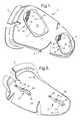
- FIG. 1is a perspective view, electrode side up, of an electrode positioner for the dorsal side of a splint
- FIG. 2is a perspective view of the rear side of the electrode positioner of FIG. 1;
- FIG. 3is a side view of a terminal element of the electrode positioner
- FIG. 4represents a perspective view, electrode side up, of an electrode positioner for the palmar side of a splint
- FIG. 5is a perspective view of the rear side of the electrode positioner of FIG. 4, and
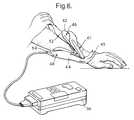
- FIG. 6is a perspective view of a patient's arm wearing a splint, with the positioner of FIG. 1 being introduced between the dorsal portion of the splint and the patient's skin.
- FIG. 1an electrode positioner designed for the dorsal part of a forearm, comprising a scoop-like structure 2 advantageously produced from plastic sheeting by vacuum-forming and provided with beaded rims 4 which, at the wider end of structure 2 , turn into a heel 5 and a flange 6 , which latter is used to facilitate handling of structure 2 .
- two surface electrodes 8comprised of an electrode carrier 10 attached to the concave surface 3 of structure 2 with the aid of a double-faced adhesive patch (not shown), the electrode proper 12 in the form of a fine wire mesh fixedly attached to electrode carrier 10 , and a skin-contacting pad 14 .
- a detailed description of surface electrode 8can be found in co-pending Israel Patent Application No. 135,175. Surface electrodes 8 activate extensor muscles.
- each electrode carrier 10there are two small holes 16 on the rim of each electrode carrier 10 , so disposed that their respective centers are located on the edges of the rims, each hole 16 being located directly opposite index markings 18 provided on the rims. The purpose of these holes will become apparent further below.
- FIG. 2shows the rear side of structure 2 , the surface 20 of which is obviously convex. Seen are two terminal elements 22 , one for each of surface electrodes 8 (FIG. 1 ). An enlarged side view of element 22 is shown in FIG. 3 . There is seen a flat spring 24 prebent to a flat, arch-like shape and carrying a tapered projection 26 . At one of its ends, spring 24 is provided with a tongue-like appendage 28 which, by means of an advantageously hollow rivet 30 , electrically connects terminal element 22 with electrode 12 (pad 14 not shown). At one end, spring 24 is fixedly attached to structure 2 by means of a rivet 32 . The other end of spring 24 is provided with an elongated hole 34 and is held down by a washer 36 that permits spring 24 to stretch when it is flattened by pressure on projection 26 . The purpose of this arrangement will be explained further below.
- FIG. 4illustrates the counterpart of the electrode positioner shown in FIG. 1, namely, the electrode positioner designed for the palmar portion of the forearm.
- Seenis scoop-like structure 2 ′, which is of a slightly different configuration, designed as it is for the palmar section of the splint.
- Beaded rims 4at the wide end of structure 2 ′, turn into a cable duct 38 and an ear-like grip 40 for handling structure 2 ′.
- the single surface electrode 8 ′mounted on concave surface 3 ′, is meant to activate flexor muscles and consists of the same components as surface electrodes 8 seen in FIG. 1 .
- FIG. 5is the analogue of FIG. 2, also showing terminal element 22 .
- the electrode positioners according to the present inventionare advantageously supplied in sets, in which each of the electrodes is of a different size location and orientation.
- each of the electrodesis of a different size location and orientation.
- trial-and-error selection from a set of seven electrode positionersfour for extensors and three for flexors
- sets either larger or smaller, or of different proportions of flexor and extensor positionersare definitely within the scope of the present invention.
- Each setalso includes a number of surface electrodes 8 and 8 ′ of different sizes, ready for mounting by the clinician, as will be described further below.
- the electrode positioneris selected by the clinician, or, as will be explained, by the patient himself, the positioner must be introduced between the patient's skin and the interior surface of the relevant splint member, as seen in FIG. 6 . In either case, two conditions must be met:
- the electrode positionerUpon being fully introduced, the electrode positioner must encounter a definite stop to ensure that its final position relative to the splint is always the same.
- FIG. 6shows one way in which these conditions can be fulfilled.
- Seenis a crocodile-type splint having an upper jaw 42 and a lower jaw 44 , with a bow-like member 45 defining and stabilizing the spatial relationship between limb and splint.
- Further provided in the splintare holes 46 , 47 and 48 .
- the distance between, and location of, holes 46 and 47equals the distance between, and location of, the conical projections 26 of FIG. 2, so that electrode positioner 2 is fully inserted when spring-loaded projections 26 index in holes 46 , 47 , thereby effectively retaining the positioner.
- the stimulation currentcan then be supplied through these holes.
- An alternative way to define the final position of the electrode positioner with splints lacking holes 46 , 47 and 48is to use edges 52 , 54 , respectively, of upper and lower jaws 42 , 44 as stops against which abuts heel 5 (FIGS. 1, 2 ) of the extensor electrode positioner, or rims 41 of the flexor electrode positioner (FIG. 5 ).
- Stimulation currentcan also be supplied by soldering the ends of cables from stimulator 56 into hollow rivets 30 (FIG. 3 ).
- the electrode positioners according to the present inventioncan be used in two different modes:
- the clinicianfits an as yet electrode-less splint onto the patient's forearm and then, in rapid succession, assesses the response of the limb to the different electrode arrays and combinations of the sets of electrode positioners, selecting the pair of positioners that produces the best results. The clinician then removes the splint and, with the selected positioners still in position, proceeds to indicate the future positions of the permanent surface electrodes to be attached to the splint by using a thin marker and marking dots on the inside surfaces of the respective splint sections through holes 16 (FIGS. 1, 4 ).
- the cliniciannow removes the electrode positioners, selects electrodes of the proper size from the electrode set, peels off the protective silicon paper from the adhesive patch at the back of each electrode, and then mounts each permanent electrode so that its index marks (reference numeral 18 in FIGS. 1 and 4) are in alignment with the dots on the splint sections. Electrical connection is provided by piercing the mounted electrode to transfer the location of the threaded metal terminals mounted in holes 46 , 47 , 48 of the splint (FIG. 6) and using a screw driven through the pierced electrode to establish permanent contact.
- the cliniciandoes not mount a permanent electrode, but selects a number of electrode positioners for the patient, who, returning home, can now insert his own choice of positioners according to the limb position he desires, which in turn depends on the activity he wishes to carry out, or the exercise program preferred.
Landscapes
- Health & Medical Sciences (AREA)
- Engineering & Computer Science (AREA)
- Biomedical Technology (AREA)
- Nuclear Medicine, Radiotherapy & Molecular Imaging (AREA)
- Radiology & Medical Imaging (AREA)
- Life Sciences & Earth Sciences (AREA)
- Animal Behavior & Ethology (AREA)
- General Health & Medical Sciences (AREA)
- Public Health (AREA)
- Veterinary Medicine (AREA)
- Electrotherapy Devices (AREA)
- Orthopedics, Nursing, And Contraception (AREA)
Abstract
Description
Claims (9)
Applications Claiming Priority (3)
| Application Number | Priority Date | Filing Date | Title |
|---|---|---|---|
| IL135585 | 2000-04-11 | ||
| IL135585AIL135585A (en) | 2000-04-11 | 2000-04-11 | Electrode positioner for a splint to be used for muscle stimulation |
| IL135,585 | 2000-04-11 |
Publications (2)
| Publication Number | Publication Date |
|---|---|
| US20020032475A1 US20020032475A1 (en) | 2002-03-14 |
| US6496739B2true US6496739B2 (en) | 2002-12-17 |
Family
ID=11074047
Family Applications (1)
| Application Number | Title | Priority Date | Filing Date |
|---|---|---|---|
| US09/832,110Expired - Fee RelatedUS6496739B2 (en) | 2000-04-11 | 2001-04-11 | Electrode positioner for a splint to be used for muscle stimulation |
Country Status (10)
| Country | Link |
|---|---|
| US (1) | US6496739B2 (en) |
| EP (1) | EP1145732B1 (en) |
| JP (1) | JP4044299B2 (en) |
| AT (1) | ATE288299T1 (en) |
| AU (1) | AU771624B2 (en) |
| CA (1) | CA2343273A1 (en) |
| DE (1) | DE60108679T2 (en) |
| ES (1) | ES2237532T3 (en) |
| IL (1) | IL135585A (en) |
| NO (1) | NO20011681L (en) |
Cited By (9)
| Publication number | Priority date | Publication date | Assignee | Title |
|---|---|---|---|---|
| US20070123951A1 (en)* | 2005-05-24 | 2007-05-31 | Leon Boston | Tremor reduction systems suitable for self-application and use in disabled patients |
| US8209022B2 (en) | 2005-11-16 | 2012-06-26 | Bioness Neuromodulation Ltd. | Gait modulation system and method |
| US8209036B2 (en) | 2005-11-16 | 2012-06-26 | Bioness Neuromodulation Ltd. | Orthosis for a gait modulation system |
| US8788049B2 (en) | 2006-05-01 | 2014-07-22 | Bioness Neuromodulation Ltd. | Functional electrical stimulation systems |
| US8868217B2 (en) | 2011-06-27 | 2014-10-21 | Bioness Neuromodulation Ltd. | Electrode for muscle stimulation |
| US8972017B2 (en) | 2005-11-16 | 2015-03-03 | Bioness Neuromodulation Ltd. | Gait modulation system and method |
| US9095417B2 (en) | 2011-02-07 | 2015-08-04 | Bioness Neuromodulation Ltd. | Adjustable orthosis for electrical stimulation of a limb |
| US9867985B2 (en) | 2014-03-24 | 2018-01-16 | Bioness Inc. | Systems and apparatus for gait modulation and methods of use |
| US11077300B2 (en) | 2016-01-11 | 2021-08-03 | Bioness Inc. | Systems and apparatus for gait modulation and methods of use |
Families Citing this family (7)
| Publication number | Priority date | Publication date | Assignee | Title |
|---|---|---|---|---|
| JP2009511567A (en) | 2005-10-14 | 2009-03-19 | ヘナーロ カサス・ハッサン | Natural pesticide |
| ES2580132T3 (en) | 2008-02-05 | 2016-08-19 | Compex Medical S.A. | Stimulation Orthosis |
| US8548558B2 (en) | 2008-03-06 | 2013-10-01 | Covidien Lp | Electrode capable of attachment to a garment, system, and methods of manufacturing |
| US8868216B2 (en)* | 2008-11-21 | 2014-10-21 | Covidien Lp | Electrode garment |
| US11541228B2 (en)* | 2014-01-03 | 2023-01-03 | Axiobionics | Upper extremity biosleeve |
| CA2949359A1 (en)* | 2014-05-16 | 2015-11-19 | Axiobionics | Lower back electrical stimulator |
| CN120456953A (en)* | 2022-12-23 | 2025-08-08 | 诺沃库勒有限责任公司 | System and method for array positioning |
Citations (5)
| Publication number | Priority date | Publication date | Assignee | Title |
|---|---|---|---|---|
| US5330516A (en) | 1991-03-28 | 1994-07-19 | Ben-Gurion University Of The Negev Research & Development Authority | Device for generating hand function |
| WO1995010323A1 (en) | 1993-10-13 | 1995-04-20 | University Of Alberta | Garment for applying controlled electrical stimulation to restore motor function |
| US5540735A (en) | 1994-12-12 | 1996-07-30 | Rehabilicare, Inc. | Apparatus for electro-stimulation of flexing body portions |
| US5766236A (en)* | 1996-04-19 | 1998-06-16 | Detty; Gerald D. | Electrical stimulation support braces |
| WO1998053877A1 (en) | 1997-05-30 | 1998-12-03 | Neuromotion Inc. | Assembly for holding electrodes of a functional electrical stimulation device |
- 2000
- 2000-04-11ILIL135585Apatent/IL135585A/enactiveIP Right Grant
- 2001
- 2001-04-03EPEP01303161Apatent/EP1145732B1/ennot_activeExpired - Lifetime
- 2001-04-03ESES01303161Tpatent/ES2237532T3/ennot_activeExpired - Lifetime
- 2001-04-03DEDE60108679Tpatent/DE60108679T2/ennot_activeExpired - Fee Related
- 2001-04-03ATAT01303161Tpatent/ATE288299T1/ennot_activeIP Right Cessation
- 2001-04-04NONO20011681Apatent/NO20011681L/ennot_activeApplication Discontinuation
- 2001-04-04AUAU33438/01Apatent/AU771624B2/ennot_activeCeased
- 2001-04-05CACA002343273Apatent/CA2343273A1/ennot_activeAbandoned
- 2001-04-11USUS09/832,110patent/US6496739B2/ennot_activeExpired - Fee Related
- 2001-04-11JPJP2001112402Apatent/JP4044299B2/ennot_activeExpired - Fee Related
Patent Citations (5)
| Publication number | Priority date | Publication date | Assignee | Title |
|---|---|---|---|---|
| US5330516A (en) | 1991-03-28 | 1994-07-19 | Ben-Gurion University Of The Negev Research & Development Authority | Device for generating hand function |
| WO1995010323A1 (en) | 1993-10-13 | 1995-04-20 | University Of Alberta | Garment for applying controlled electrical stimulation to restore motor function |
| US5540735A (en) | 1994-12-12 | 1996-07-30 | Rehabilicare, Inc. | Apparatus for electro-stimulation of flexing body portions |
| US5766236A (en)* | 1996-04-19 | 1998-06-16 | Detty; Gerald D. | Electrical stimulation support braces |
| WO1998053877A1 (en) | 1997-05-30 | 1998-12-03 | Neuromotion Inc. | Assembly for holding electrodes of a functional electrical stimulation device |
Cited By (23)
| Publication number | Priority date | Publication date | Assignee | Title |
|---|---|---|---|---|
| US7643882B2 (en) | 2005-05-24 | 2010-01-05 | Leon Boston | Tremor reduction systems suitable for self-application and use in disabled patients |
| US20070123951A1 (en)* | 2005-05-24 | 2007-05-31 | Leon Boston | Tremor reduction systems suitable for self-application and use in disabled patients |
| US10076656B2 (en) | 2005-11-16 | 2018-09-18 | Bioness Neuromodulation Ltd. | Gait modulation system and method |
| US8209022B2 (en) | 2005-11-16 | 2012-06-26 | Bioness Neuromodulation Ltd. | Gait modulation system and method |
| US8209036B2 (en) | 2005-11-16 | 2012-06-26 | Bioness Neuromodulation Ltd. | Orthosis for a gait modulation system |
| US8694110B2 (en) | 2005-11-16 | 2014-04-08 | Bioness Neuromodulation Ltd. | Orthosis for gait modulation |
| US11058867B2 (en) | 2005-11-16 | 2021-07-13 | Bioness Neuromodulation Ltd. | Orthosis for a gait modulation system |
| US8972017B2 (en) | 2005-11-16 | 2015-03-03 | Bioness Neuromodulation Ltd. | Gait modulation system and method |
| US10080885B2 (en) | 2005-11-16 | 2018-09-25 | Bioness Neuromodulation Ltd. | Orthosis for a gait modulation system |
| US10543365B2 (en) | 2006-05-01 | 2020-01-28 | Bioness Neuromodulation Ltd. | Functional electrical stimulation systems |
| US8788049B2 (en) | 2006-05-01 | 2014-07-22 | Bioness Neuromodulation Ltd. | Functional electrical stimulation systems |
| US10016598B2 (en) | 2006-05-01 | 2018-07-10 | Bioness Neuromodulation Ltd. | Functional electrical stimulation systems |
| US9415205B2 (en) | 2006-05-01 | 2016-08-16 | Bioness Neuromodulation Ltd. | Functional electrical stimulation systems |
| US11247048B2 (en) | 2006-05-01 | 2022-02-15 | Bioness Neuromodulation Ltd. | Functional electrical stimulation systems |
| US9095417B2 (en) | 2011-02-07 | 2015-08-04 | Bioness Neuromodulation Ltd. | Adjustable orthosis for electrical stimulation of a limb |
| US8868217B2 (en) | 2011-06-27 | 2014-10-21 | Bioness Neuromodulation Ltd. | Electrode for muscle stimulation |
| US10850098B2 (en) | 2014-03-24 | 2020-12-01 | Bioness Inc. | Systems and apparatus for gait modulation and methods of use |
| US10086196B2 (en) | 2014-03-24 | 2018-10-02 | Bioness Inc. | Systems and apparatus for gait modulation and methods of use |
| US9867985B2 (en) | 2014-03-24 | 2018-01-16 | Bioness Inc. | Systems and apparatus for gait modulation and methods of use |
| US11691009B2 (en) | 2014-03-24 | 2023-07-04 | Bioness Inc. | Systems and apparatus for gait modulation and methods of use |
| US12377266B2 (en) | 2014-03-24 | 2025-08-05 | Bioness Medical Inc. | Systems and apparatus for gait modulation and methods of use |
| US11077300B2 (en) | 2016-01-11 | 2021-08-03 | Bioness Inc. | Systems and apparatus for gait modulation and methods of use |
| US11724106B2 (en) | 2016-01-11 | 2023-08-15 | Bioness Inc. | Systems and apparatus for gait modulation and methods of use |
Also Published As
| Publication number | Publication date |
|---|---|
| AU3343801A (en) | 2001-10-18 |
| DE60108679T2 (en) | 2006-05-11 |
| AU771624B2 (en) | 2004-04-01 |
| ES2237532T3 (en) | 2005-08-01 |
| JP4044299B2 (en) | 2008-02-06 |
| US20020032475A1 (en) | 2002-03-14 |
| DE60108679D1 (en) | 2005-03-10 |
| EP1145732A2 (en) | 2001-10-17 |
| EP1145732B1 (en) | 2005-02-02 |
| JP2001346889A (en) | 2001-12-18 |
| IL135585A (en) | 2006-10-31 |
| CA2343273A1 (en) | 2001-10-11 |
| IL135585A0 (en) | 2001-05-20 |
| EP1145732A3 (en) | 2002-01-02 |
| ATE288299T1 (en) | 2005-02-15 |
| NO20011681L (en) | 2001-10-12 |
| NO20011681D0 (en) | 2001-04-04 |
Similar Documents
| Publication | Publication Date | Title |
|---|---|---|
| US6496739B2 (en) | Electrode positioner for a splint to be used for muscle stimulation | |
| US6438428B1 (en) | Electrical stimulation compress | |
| US8473072B2 (en) | Customizable medical electrode | |
| US5540735A (en) | Apparatus for electro-stimulation of flexing body portions | |
| EP3479870B1 (en) | Electrode for muscle stimulation | |
| US4267838A (en) | Apparatus for electrical impulse acupressure treatment | |
| US6788979B1 (en) | Electrical stimulation compress kit | |
| US11779505B2 (en) | Finger exerciser | |
| GB2457025A (en) | Garment for carrying electrotherapy electrodes | |
| JP3157837U (en) | Finger Suck Type Electrode Body for Low Frequency Therapy Device | |
| WO1992008516A1 (en) | Earpiece for electrical stimulation of acupuncture point | |
| JP2515900B2 (en) | Low frequency therapy device | |
| JP3012868U (en) | Portable massage equipment | |
| JPH063617Y2 (en) | Conductive pad for electric therapy device | |
| WO2024256828A1 (en) | Electrical stimulation system | |
| AU2012277312B2 (en) | Electrode for muscle stimulation | |
| Oskarsdottir et al. | Application of electrode matrix to locate stimulation sites for hand functions of SCI patients | |
| IL113608A (en) | System and method for muscle motor point location and stimulating electrode positioning | |
| JPH08126705A (en) | Electrode material |
Legal Events
| Date | Code | Title | Description |
|---|---|---|---|
| AS | Assignment | Owner name:N.E.S.S. NEUROMUSCULAR ELECTRICAL STIMULATION SYST Free format text:ASSIGNMENT OF ASSIGNORS INTEREST;ASSIGNOR:ARBEL, GIORA;REEL/FRAME:011706/0704 Effective date:20010403 | |
| FEPP | Fee payment procedure | Free format text:PAYOR NUMBER ASSIGNED (ORIGINAL EVENT CODE: ASPN); ENTITY STATUS OF PATENT OWNER: LARGE ENTITY | |
| FPAY | Fee payment | Year of fee payment:4 | |
| AS | Assignment | Owner name:BIONESS NEUROMODULATION LTD., ISRAEL Free format text:CHANGE OF NAME;ASSIGNOR:NESS NEUROMUSCULAR ELECTRICAL STIMULATION SYSTEMS, LTD.;REEL/FRAME:021383/0063 Effective date:20080128 Owner name:BIONESS NEUROMODULATION LTD.,ISRAEL Free format text:CHANGE OF NAME;ASSIGNOR:NESS NEUROMUSCULAR ELECTRICAL STIMULATION SYSTEMS, LTD.;REEL/FRAME:021383/0063 Effective date:20080128 | |
| FEPP | Fee payment procedure | Free format text:PAT HOLDER NO LONGER CLAIMS SMALL ENTITY STATUS, ENTITY STATUS SET TO UNDISCOUNTED (ORIGINAL EVENT CODE: STOL); ENTITY STATUS OF PATENT OWNER: LARGE ENTITY | |
| REMI | Maintenance fee reminder mailed | ||
| LAPS | Lapse for failure to pay maintenance fees | ||
| STCH | Information on status: patent discontinuation | Free format text:PATENT EXPIRED DUE TO NONPAYMENT OF MAINTENANCE FEES UNDER 37 CFR 1.362 | |
| FP | Lapsed due to failure to pay maintenance fee | Effective date:20101217 |