US6496324B1 - Disk drive employing method of unlatching actuator arm using VCM voltage limiting circuit to limit actuator arm velocity - Google Patents
Disk drive employing method of unlatching actuator arm using VCM voltage limiting circuit to limit actuator arm velocityDownload PDFInfo
- Publication number
- US6496324B1 US6496324B1US09/342,795US34279599AUS6496324B1US 6496324 B1US6496324 B1US 6496324B1US 34279599 AUS34279599 AUS 34279599AUS 6496324 B1US6496324 B1US 6496324B1
- Authority
- US
- United States
- Prior art keywords
- vcm
- actuator arm
- node
- coil
- velocity
- Prior art date
- Legal status (The legal status is an assumption and is not a legal conclusion. Google has not performed a legal analysis and makes no representation as to the accuracy of the status listed.)
- Expired - Lifetime
Links
- 230000000670limiting effectEffects0.000titleclaimsabstractdescription78
- 238000000034methodMethods0.000titleclaimsabstractdescription26
- 230000003213activating effectEffects0.000claimsabstractdescription9
- 230000000452restraining effectEffects0.000claimsabstractdescription5
- 238000010586diagramMethods0.000description7
- 230000008569processEffects0.000description7
- 230000004913activationEffects0.000description4
- 238000013461designMethods0.000description4
- 238000004519manufacturing processMethods0.000description4
- 238000010276constructionMethods0.000description3
- 239000002184metalSubstances0.000description3
- 238000001208nuclear magnetic resonance pulse sequenceMethods0.000description3
- 229920006395saturated elastomerPolymers0.000description3
- 238000003491arrayMethods0.000description2
- 230000002860competitive effectEffects0.000description2
- 230000002829reductive effectEffects0.000description2
- 230000004044responseEffects0.000description2
- 230000020347spindle assemblyEffects0.000description2
- 230000001133accelerationEffects0.000description1
- 230000003321amplificationEffects0.000description1
- 238000004458analytical methodMethods0.000description1
- 238000012937correctionMethods0.000description1
- 230000008878couplingEffects0.000description1
- 238000010168coupling processMethods0.000description1
- 238000005859coupling reactionMethods0.000description1
- 238000001514detection methodMethods0.000description1
- 238000003199nucleic acid amplification methodMethods0.000description1
- 238000012545processingMethods0.000description1
- 238000012827research and developmentMethods0.000description1
- 230000002441reversible effectEffects0.000description1
- 230000001360synchronised effectEffects0.000description1
- 230000007704transitionEffects0.000description1
Images


Classifications
- G—PHYSICS
- G11—INFORMATION STORAGE
- G11B—INFORMATION STORAGE BASED ON RELATIVE MOVEMENT BETWEEN RECORD CARRIER AND TRANSDUCER
- G11B5/00—Recording by magnetisation or demagnetisation of a record carrier; Reproducing by magnetic means; Record carriers therefor
- G11B5/48—Disposition or mounting of heads or head supports relative to record carriers ; arrangements of heads, e.g. for scanning the record carrier to increase the relative speed
- G11B5/54—Disposition or mounting of heads or head supports relative to record carriers ; arrangements of heads, e.g. for scanning the record carrier to increase the relative speed with provision for moving the head into or out of its operative position or across tracks
- G—PHYSICS
- G11—INFORMATION STORAGE
- G11B—INFORMATION STORAGE BASED ON RELATIVE MOVEMENT BETWEEN RECORD CARRIER AND TRANSDUCER
- G11B21/00—Head arrangements not specific to the method of recording or reproducing
- G11B21/02—Driving or moving of heads
- G11B21/12—Raising and lowering; Back-spacing or forward-spacing along track; Returning to starting position otherwise than during transducing operation
- G—PHYSICS
- G11—INFORMATION STORAGE
- G11B—INFORMATION STORAGE BASED ON RELATIVE MOVEMENT BETWEEN RECORD CARRIER AND TRANSDUCER
- G11B21/00—Head arrangements not specific to the method of recording or reproducing
- G11B21/16—Supporting the heads; Supporting the sockets for plug-in heads
- G11B21/22—Supporting the heads; Supporting the sockets for plug-in heads while the head is out of operative position
Definitions
- the present inventionrelates to disk drives. More particularly, the present invention relates to a disk drive employing a method of unlatching an actuator arm using a voice coil motor (VCM) voltage limiting circuit to limit actuator arm velocity.
- VCMvoice coil motor
- a hard disk drivemust be relatively inexpensive, and must accordingly embody a design that is adapted for low-cost mass production.
- itmust provide substantial capacity, rapid access to data, and reliable performance.
- Numerous manufacturerscompete in this huge market and collectively conduct substantial research and development, at great annual cost, to design and develop innovative hard disk drives to meet increasingly demanding customer requirements.
- a head disk assembly of a disk driveincludes an actuator assembly having a voice coil motor (VCM), an actuator arm extending from the VCM, and a transducer head disposed at the end of the actuator arm.
- VCMvoice coil motor
- the VCMincludes a coil moving in proximity to a permanent magnet. The VCM swings the actuator arm and the transducer heads back and forth over the disk to access target data tracks on the disk surface.
- the transducer headis parked away from the data tracks to protect the transducer head and the disk surface, and a latch, such as a magnetic latch, typically restrains the actuator arm in place in the head disk assembly.
- a latchsuch as a magnetic latch
- the VCMis controlled to overcome the force of the magnetic latch to move the actuator arm away from the latch, in what is referred to as unlatching the actuator arm, to position the transducer head over the data area of the disk surface.
- the actuator armmust be unlatched so that the transducer head can move radially across the disk surface while the head disk assembly is connected in either the disk drive or a servowriter.
- the actuator armmust be slowed to an actuator arm velocity which will not cause damage to the transducer head or disk surface during impact of the actuator arm against the outer diameter crash stop or the push pin.
- a first series of current pulsesare applied to the VCM in order to move the actuator arm away from the magnetic latch.
- a second series of current pulsesare then applied in the reverse direction to reduce the actuator arm velocity.
- the amplitude and widths of the second series of current pulsescan be ascertained by empirical analysis on a disk drive product.
- An example current pulse sequencecomprises an unlatch pulse period, a coast period, and a brake pulse period.
- the unlatch pulse periodtypically applies positive current to the VCM for a predetermined period of time.
- the coast periodis a predetermined period of time where zero current is applied to the VCM.
- the brake pulse periodtypically applies negative current to the VCM for a predetermined period of time.
- the predetermined time periods and the amount of current applied to the VCM during the unlatch pulse period and during the brake pulse periodmust have sufficient margins to allow for variations in the VCM and latch assembly of the particular disk drive.
- the actuator armmay return to an inner diameter crash stop and become re-latched in the latch.
- the brake pulse periodis typically employed to slow down the actuator arm velocity to a sufficiently slow velocity to permit a servo system in the disk drive to detect the servo information on the disk surface.
- the servo systememploys conventional closed loop servo control to control the actuator arm velocity and the position of the actuator arm over the disk. If the servo system, however, does not detect the servo information, the actuator arm velocity can not be controlled by the closed loop servo system. If the actuator arm velocity is not controlled by the closed loop servo system, the actuator arm velocity when the actuator arm hits the outer diameter crash stop can be at a level which causes damage to the transducer head and/or the disk.
- a disk drive that employs a ramp load designmay include a velocity feedback circuit to control the actuator arm velocity.
- the velocity feedback circuitemploys the back electromotive force (BEMF) of the VCM to monitor and control the actuator arm velocity to thereby control the speed at which the transducer head moves away from the ramp and over the disk surface.
- BEMFback electromotive force
- the velocity feedback circuitincludes complex closed loop circuitry to measure the BEMF and compute actuator arm velocity that is used for controlling the amount of current applied to the VCM.
- the inventioncan be regarded as a method of unlatching an actuator arm from a latch restraining the actuator arm in a disk drive.
- the disk driveincludes a first node, a second node, and a voice coil motor (VCM) coupled to the actuator arm, the VCM including a coil connected between the first node and the second node.
- the methodincludes the step of applying a voltage between the first node and the second node to cause current to flow through the coil in order to move the actuator arm away from the latch at a variable actuator arm velocity.
- the methodalso includes the step of temporarily activating a VCM velocity control signal to enable a VCM voltage limiting circuit connected in parallel with the coil between the first node and the second node.
- the methodalso includes the step of limiting the voltage applied across the coil to a predetermined VCM voltage level with the enabled VCM voltage limiting circuit in order to limit the actuator arm velocity.
- the inventioncan also be regarded as a disk drive connectable to a power supply.
- the disk driveincludes an actuator arm, a latch for restraining the actuator arm, a first node, a second node, and a voice coil motor (VCM) coupled to the actuator arm.
- the VCMhas a coil connected between the first node and the second node.
- the disk drivefurther includes a VCM driver coupled to the power supply for applying a voltage between the first node and the second node to cause current to flow through the coil in order to move the actuator arm away from the latch at a variable actuator arm velocity.
- the disk drivefurther includes control means for temporarily activating a VCM velocity control signal.
- the disk drivefurther includes a VCM voltage limiting circuit connected in parallel with the coil between the first node and the second node.
- the VCM voltage limiting circuitis responsive to the VCM velocity control signal being temporarily activated for limiting the voltage applied across the coil to a predetermined VCM voltage level in order to limit the actuator arm velocity.
- FIG. 1is a block diagram of a hard disk drive employing a method of unlatching an actuator arm using a VCM voltage limiting circuit to limit the actuator arm velocity.
- FIG. 2is a block diagram of a head disk assembly (HDA) placed in a servowriter employing a method of unlatching an actuator arm using a VCM voltage limiting circuit to limit the actuator arm velocity.
- HDAhead disk assembly
- FIG. 3is a more detailed diagram of an HDA that is connectable in the disk drive of FIG. 1 or in the servowriter of FIG. 2 .
- FIG. 4is a schematic diagram of the VCM voltage limiting circuit employed in the servowriter of FIG. 2 .
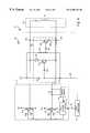
- FIG. 5is a schematic diagram of the VCM voltage limiting circuit employed in the disk drive of FIG. 1 .
- a hard disk drive 30employs a method of unlatching an actuator arm, such as an actuator arm 62 , using a VCM voltage limiting circuit, such as VCM voltage limiting circuit 302 , to limit velocity of the actuator arm.
- Disk drive 30includes a disk controller circuit board 32 and a head disk assembly (HDA) 34 .
- Disk controller circuit board 32includes circuitry and processors which provide an intelligent disk control system interface between a host system 36 and HDA 34 for execution of read and write commands.
- Host system 36can include a microprocessor based data processing system such as a personal computer, or other system capable of performing a sequence of logical operations.
- Host system 36includes a standard power supply 38 which supplies power to disk controller circuit board 32 via a power supply connector 40 . Data is transmitted between host system 36 and disk controller circuit board 32 via a host bus connector 42 .
- HDA 34includes an actuator assembly 44 , a preamplifier 46 , and a disk assembly 48 .
- Disk assembly 48includes a plurality of magnetic media disks, such as indicated at 50 .
- Disks 50are stacked on a spindle assembly 52 .
- Spindle assembly 52is mechanically coupled to a spindle motor 54 for rotating disks 50 at a high rate of speed.
- Each disk 50includes two disk surfaces capable of storing data thereon, such as indicated at 56 and 58 .
- Actuator assembly 44includes a voice coil motor (VCM) 60 and actuator arms 62 extending from VCM 60 .
- Each actuator arm 62corresponds to a respective disk surface such as 56 or 58 .
- VCMvoice coil motor
- a transducer head 64is disposed at the end of each actuator arm 62 , and each transducer head 64 is associated with a disk surface 56 or 58 .
- Transducer heads 64communicate with disk controller circuit board 32 via preamplifier 46 for reading and writing data to the transducer head's associated disk surface.
- Preamplifier 46is electrically coupled to transducer head 64 for receipt and amplification of position signals representative of the position of transducer head 64 .
- Preamplifier 46provides an amplified signal to a read/write channel 68 of disk controller circuit board 32 .
- Read/write channel 68performs encoding and decoding of data written to and read from disks 50 .
- VCM 60includes a coil 70 moving in proximity to a permanent magnet 72 .
- Actuator arms 62are coupled to VCM 60 .
- VCM 60swings actuator arms 62 and their corresponding transducer heads 64 over their associated disk surfaces 56 or 58 to access target data tracks formed on the associated disk surface.
- Disk control circuit board 32includes a host interface and disk controller (HIDC) integrated circuit 74 .
- HIDC 74includes a host interface 76 , a buffer controller 78 , and a disk controller 80 .
- Host interface 76communicates with host system 36 via host bus connector 42 by receiving commands and data from and transmitting status and data back to host system 36 .
- Buffer controller 78controls a buffer memory 82 employed for storing data from host system 36 which is to be written to disks 50 .
- buffer controller 78controls buffer memory 82 for storing read data from disks 50 to be transmitted to host system 36 via host interface 76 .
- Buffer memory 82typically comprises random access memory (RAM), such as dynamic random access memory (DRAM).
- RAMrandom access memory
- DRAMdynamic random access memory
- Disk controller 80sends data to and receives data from read/write channel 68 . Disk controller 80 also provides for error correction and error detection on data transmitted to or read from disk 50 .
- An interface processor 84handles the flow of data and commands received by host interface 76 by sending commands to and reading status from disk controller 80 .
- Interface processor 84ascertains which commands to process from host system 36 and when to process these commands, and directs other tasks performed by disk controller 80 .
- a servo processor 86commands a servo controller 88 to control the position of transducer head 64 over disk 50 at a target data track for subsequent execution of read or write commands.
- Servo processor 86receives a representative form of the position signals sensed by transducer head 64 and amplified by preamplifier 46 via read/write channel 68 and servo controller 88 and performs calculations to position transducer head 64 relative to its associated disk surface.
- Servo processor 86commands a digital-to-analog converter (DAC) 90 in servo controller 88 to provide a corresponding analog signal representing desired VCM coil current on a line 91 to a VCM driver 92 .
- DACdigital-to-analog converter
- VCM driver 92responds to the analog signal on line 91 to provide a current to VCM 60 .
- Poweris supplied from standard power supply 38 through power supply connector 40 to VCM driver 92 via a power line 99 . More specifically, the current from VCM driver 92 is provided to coil 70 of VCM 60 and causes actuator arm 62 to swing and thereby move transducer head 64 over an associated disk surface 56 or 58 to access target data tracks.
- Servo processor 86also provides commands servo controller 88 to control the rotational velocity of spindle motor 54 .
- a DAC 94 in servo controller 88provides an analog signal to a spindle motor driver 96 .
- Spindle motor driver 96responds to the analog signal from DAC 94 to drive and thereby control the speed of spindle motor 54 .
- Spindle motor driver 96also detects a back electromotive force (BEMF) of spindle motor 54 and provides a signal representative of the spin-rate of spindle motor 54 to servo controller 88 which converts the signal into a monitored velocity signal which can be read by servo processor 86 . In this way, servo processor 86 can control the spin-rate of spindle motor 54 via servo controller 88 to maintain a substantially constant spin-rate of rotating disks 50 .
- BEMFback electromotive force
- Disk system operational programsare stored in non-volatile memory 97 , such as read-only memory (ROM) or flash memory, and can be all or partially loaded into RAM 98 for execution from RAM 98 or both RAM 98 and non-volatile memory 97 .
- portions of disk system operational programsare stored on reserve cylinders on disk 50 .
- servo processor 86may have integrated or separate memory (not shown) for storage of servo programs.
- the current track position of transducer head 64is stored by servo processor 86 to determine a required seek distance between the current data track and a target data track. Based on the required seek distance, servo processor 86 retrieves a corresponding read or write seek profile and provides a digital signal command to DAC 90 corresponding to the seek profile. DAC 90 provides a corresponding analog signal to VCM driver 92 representative of the seek profiles. VCM driver 92 provides a current output to coil 70 of VCM 60 for acceleration and/or deceleration of actuator arm 62 to perform a seek operation to move transducer head 64 from the current data track to the target data track.
- a position error signalis provided via preamplifier 46 , read/write channel 68 , and servo controller 88 to servo processor 86 to provide a representative position of transducer head 64 relative to its associated disk surface 56 or 58 .
- a read or write commandis executed to read data from or write data to the target data track.
- HDA 34is placed in a servowriter (servo track writer) 134 employing a method of unlatching an actuator arm, such as an actuator arm 62 , using a VCM voltage limiting circuit, such as VCM voltage limiting circuit 202 , to limit velocity of the actuator arm.
- Servowriter 134is employed for precisely writing servo tracks (i.e., servo sectors) on disk surfaces 56 / 58 in HDA 34 .
- Servowriter 134writes a clock track 178 on disk surface 56 , wherein the clock track provides a continuous stream of reference timing information to servowriter 134 during the servo writing process.
- transducer head 64While positioned within servowriter 134 during the manufacturing process, transducer head 64 communicates with servowriter 134 via preamplifier 46 and a line 160 for writing servo sectors on the associated disk surface 56 .
- Preamplifier 46receives and transmits signals to and from a servowriter pattern generator 172 via a line 102 .
- Servowriter 134includes clock head assembly 166 , clock head preamplifier and pulse detector (pulse detector) 168 , phase locked-loop (PLL) 170 , pattern generator 172 , positioning system 174 , and spindle speed controller 176 .
- Clock head assembly 166initially operates to write clock track 178 on disk surface 56 .
- Clock assembly 166also cooperates with pulse detector 168 and PLL 170 to provide a reference timing clock to pattern generator 172 by reading the clock track 178 .
- Pattern generator 172operates to provide servo information, for writing servo tracks, synchronized to the reference timing clock during rotation of disk 50 , which is rotatably controlled by spindle speed controller 176 .
- Positioning system 174operates to incrementally move the transducer head 64 in an arcuate path from an outer diameter to an inner diameter of the disk for writing each servo track.
- Clock head assembly 166includes clock arm 180 which extends over disk surface 56 .
- a clock head 182is disposed at the end of clock arm 180 .
- Clock head 182is electrically coupled to pulse detector 168 via connecting means 184 .
- Clock head 182communicates with pattern generator 172 via pulse detector 168 and PLL 170 for writing clock track 178 on disk surface 56 and subsequently reading the clock track 178 for providing the reference timing clock to pattern generator 172 .
- Clock head preamplifier and pulse detector 168receives signals from clock head 182 representative of magnetic transitions which form the clock track 178 on disk surface 56 .
- Pulse detector 168is electrically coupled to PLL 170 via connecting means 186 and provides an amplified signal to PLL 170 .
- PLL 170operates to lock onto the reference timing clock provided by the clock track 178 , and provides a reference timing clock to pattern generator 172 which has been adjusted to compensate for any speed variations in the rotation of disk 50 .
- Positioning system 174provides for radial positioning of the transducer head 64 during the servo writing process.
- positioning system 174utilizes a laser interferometer positioning system for precisely and incrementally moving the transducer head 64 in an arcuate path from track to track during the servo writing process.
- Positioning system 174includes a servo processor 186 , a server controller 188 , a VCM driver 192 , a motor driver 196 , and a DC motor 198 .
- Servo processor 186commands servo controller 188 to control the position of the transducer head 64 over disk 50 during the servo writing process.
- Servo processor 186commands a DAC 190 in servo controller 188 to provide a corresponding analog signal representing desired VCM coil current on a line 191 to VCM driver 192 .
- VCM driver 192responds to the analog signal representing desired VCM coil current on line 191 to provide a corresponding DC current to VCM 60 .
- the DC current from VCM drive 192is provided to coil 70 of VCM 60 and causes actuator arm 62 to swing and thereby bias actuator assembly 44 against a push-pin 106 of servowriter 134 .
- Push-pin 106is slideably mounted in a slot 107 during the servo writing process and is moved incrementally via positioning system 174 . Because actuator assembly 44 is biased against push-pin 106 , actuator arm 62 follows push-pin 106 and incrementally moves from track to track.
- Servo processor 186also commands a DAC 194 in servo controller 188 to provide a corresponding analog signal to motor driver 196 .
- Motor driver 196responds to the analog signal from DAC 194 to provide a corresponding DC current to DC motor 198 which is mechanically coupled to push-pin 106 via coupling means 199 .
- DC motor 198is controlled by servo controller 188 to incrementally move push-pin 106 to cause actuator assembly 44 , which is biased against push-pin 106 , to incrementally move from track to track.
- HDA 34includes a crash stop plate 108 which is fixedly fastened to HDA 34 with a screw 109 .
- a magnetic latch 110is attached to crash stop plate 108 .
- Magnetic latch 110includes an inner diameter crash stop 112 attached to crash stop plate 108 and a permanent magnet 114 attached to inner diameter crash stop 112 .
- inner diameter crash stop 112is integral to crash stop plate 108 .
- a metal tab 116is attached to VCM 60 .
- magnetic latch 110holds metal tab 116 with magnetic force to thereby restrain and hold actuator arms 62 at the inner diameter crash stop 112 .
- currentis provided to VCM 60 to release metal tab 116 from magnetic latch 110 and move actuator arm 62 away from magnetic latch 110 to thereby move transducer head 64 towards the outer diameter of disk 50 at a variable actuator arm velocity.
- actuator arm 62When HDA 34 is connected to disk controller circuit board 32 in disk drive 30 , actuator arm 62 is stopped from moving past the outer diameter of disk 50 by an outer diameter crash stop 118 attached to crash stop plate 108 .
- outer diameter crash stop 118is integral to crash stop plate 108 .
- actuator arm 62is stopped from moving past the outer diameter of disk 50 by push-pin 106 .
- the below described embodimentsrefer to employing a VCM voltage limiting circuit to limit actuator arm velocity, such as to a substantially constant and safe actuator arm velocity, after releasing and moving actuator arm 62 away from magnetic latch 110 in head disk assembly 34 .
- the below described VCM voltage limiting circuitscan also be employed to limit the actuator arm velocity after releasing and moving the actuator arm 62 from any type of latch including, but limited to: a solenoid released spring latch; a wind pressure released spring latch; or a ramp load latch.
- the below described VCM voltage limiting circuitsare useful with ramp load latches because as a transducer head flies off the ramp, the actuator arm velocity needs to be controlled so that neither the transducer head nor the disk surface is damaged.
- disk drive 30includes VCM voltage limiting circuit 302 connected in parallel with coil 70 between a first node 306 and a second node 308 .
- Servo processor 86commands DAC 90 in servo controller 88 to provide the corresponding analog signal representing desired VCM coil current on line 91 to VCM driver 92 .
- VCM driver 92responds to the analog signal on line 91 to provide a corresponding current to VCM 60 .
- VCM driver 92is controlled to apply a voltage V (from power supply 38 ) between first node 306 and second node 308 to cause current to flow through coil 70 of VCM 60 in order to release and move actuator arm 62 away from magnetic latch 110 at a variable actuator arm velocity, wherein the current has a magnitude that is preferably determined by servo controller 88 .
- VCM driver 92is controlled so that current is provided to coil 70 of VCM 60 in the form of unlatch current pulses which typically include forward and backward exciting current pulses to provide a torque for releasing and moving actuator arm 62 away from magnetic latch 110 .
- VCM voltage limiting circuit 302is responsive to the activation of the VCM velocity control signal on line 304 for limiting the voltage V applied across coil 70 to a predetermined VCM voltage level in order to limit the actuator arm velocity to a substantially constant and safe actuator arm velocity.
- VCM voltage limiting circuit 302is preferably an open loop circuit that is temporarily activated by the VCM velocity control signal on line 304 in order to limit the actuator velocity.
- the VCM voltage limiting circuit 302responds to the activation of VCM velocity control signal on line 304 to provide a suitably low resistance path in parallel with coil 70 between first node 306 and second node 308 to limit the actuator arm velocity by limiting the BEMF generated N and applied across coil 70 of VCM 60 .
- the voltage V applied across coil 70depends on the low 2 , resistance path in parallel with coil 70 .
- VCM velocity control signal on line 304is activated, the voltage V applied across the low resistance path in parallel with coil 70 defines the predetermined VCM voltage level across coil 70
- activating the VCM velocity control signal on line 304 to provide the low resistance path in parallel with coil 70 of VCM 60reduces and limits the actuator arm velocity to a substantially constant actuator arm velocity.
- Actuator arm 62decelerates until the BEMF of VCM 60 is equivalent to the predetermined VCM voltage level across coil 70 which is defined by the voltage V applied across the low resistance path in parallel with coil 70 between first node 306 and second node 308 .
- actuator arm 62is moving at a substantially constant and safe actuator arm velocity toward outer diameter crash stop 118 .
- the safe substantially constant actuator arm velocitycorresponds to the predetermined VCM voltage level across coil 70 and can be ascertained by knowing the BEMF factor or voltage constant (Ke) of VCM 60 and the voltage Vcoil across coil 70 as shown by the following Equations I:
- BEMFKe*Vel actuator arm ( Vel actuator arm in rad/sec)
- Vel actuator arm( V ⁇ V coil )/ Ke ( Ke in V /rad/sec)
- V coilis the voltage V less the BEMF across coil 70 ;
- Vis the voltage applied from power supply 38 via VCM driver 92 between first node 306 and second node 308 which is equal to (1) the voltage applied from power supply 38 when VCM voltage limiting circuit 302 is not enabled, and (2) the predetermined VCM voltage level across coil 70 when VCM voltage limiting circuit 302 is enabled;
- BEMFis the back electromotive force of the VCM
- I coilis VCM coil current
- R tis the total resistance of the VCM coil and the power FETs driving the VCM coil from the VCM power source to ground;
- Keis the Voltage constant of the VCM i.e. the BEMF factor
- Vel actuator armis the velocity of the actuator arm coupled to the VCM.
- VCM voltage limiting circuit 302is controlled by control means including servo processor 86 and servo controller 88 via the VCM velocity control signal on line 304 , VCM voltage limiting circuit 302 can be temporarily activated at any time during the unlatch mode, and the voltage V applied across coil 70 of VCM 60 can then be held at the predetermined VCM voltage level regardless of the amount of current applied from power supply 38 via VCM driver 92 .
- a low level current from power supply 38is still applied to coil 70 of VCM 60 even after the BEMF of VCM 60 is equivalent to the predetermined VCM voltage level across coil 70 , which depends on the voltage V applied across the low resistance path in parallel with coil 70 .
- the substantially constant actuator arm velocityis a sufficiently slow velocity to permit the VCM servo system of disk drive 30 including read/write channel 68 , servo processor 86 , and servo controller 88 to detect the servo information on disk 50 .
- the VCM servo systememploys conventional closed loop servo control to control the actuator arm velocity and the position of actuator arm 62 over disk 50 .
- the substantially constant actuator arm velocityis a sufficiently slow velocity to permit actuator arm 62 to safely contact outer diameter crash stop 118 without causing damage to transducer head 64 or disk 50 .
- servowriter 134includes a VCM voltage limiting circuit 202 connected in parallel with coil 70 of VCM 60 when HDA 34 is positioned in servowriter 134 .
- VCM voltage limiting circuit 202is connected between a first node 206 and a second node 208 .
- Servo processor 186commands DAC 190 in servo controller 188 to provide a corresponding analog signal representing desired VCM coil current on line 191 to VCM driver 192 .
- VCM driver 192responds to the analog signal on line 191 to provide a corresponding current to VCM 60 .
- VCM driver 192is controlled to apply a voltage V (from an external power supply) between first node 206 and second node 208 to cause current to flow through coil 70 of VCM 60 in order to release and move actuator arm 62 away from magnetic latch 110 at a variable actuator arm velocity, wherein the current has a magnitude that is preferably determined by servo controller 188 .
- VCM driver 192is controlled so that current is provided to coil 70 of VCM 60 in the form of unlatch current pulses which typically include forward and backward exciting current pulses to provide a torque for releasing and moving actuator arm 62 away from magnetic latch 110 .
- VCM voltage limiting circuit 202is responsive to the activation of the VCM velocity control signal on line 204 for limiting the voltage V applied across coil 70 to a predetermined VCM voltage level in order to limit the actuator arm velocity to a substantially constant and safe actuator arm velocity.
- VCM voltage limiting circuit 202is preferably an open loop circuit that is temporarily activated by the VCM velocity control signal in order to limit the actuator velocity.
- the VCM voltage limiting circuit 202responds to the activation of VCM velocity control signal on line 204 to provide a suitably low resistance path in parallel with coil 70 of VCM 60 to limit the actuator arm velocity by limiting the BEMF generated across coil 70 of VCM 60 .
- the voltage V applied across coil 70depends on the low resistance path in parallel with coil 70 .
- VCM velocity control signal on line 204is activated, the voltage V applied across the low resistance path in parallel with coil 70 defines the predetermined VCM voltage level across coil 70 .
- activating the VCM velocity control signal on line 204 to provide the low resistance path in parallel with coil 70 of VCM 60reduces and limits the actuator arm velocity to a substantially constant actuator arm velocity.
- Actuator arm 62decelerates until the BEMF of VCM 60 is equivalent to the predetermined VCM voltage level across coil 70 which is defined by the voltage V applied across the low resistance path in parallel with coil 70 between first node 206 and second node 208 .
- actuator arm 62is moving at a substantially constant and safe actuator arm velocity toward outer diameter crash stop 118 and push pin 106 .
- the safe substantially constant actuator arm velocitycorresponds to the predetermined VCM voltage level across coil 70 and can be ascertained by knowing the BEMF factor (Ke) of VCM 60 and the voltage Vcoil across coil 70 as shown by the above Equations I, where V is the voltage applied from an external power supply via VCM driver 192 between first node 206 and second 208 when using VCM voltage limiting circuit 202 in servowriter 134 .
- VCM voltage limiting circuit 202is controlled by control means including servo processor 186 and servo controller 188 via the VCM velocity control signal on line 204 , VCM voltage limiting circuit 202 can be temporarily activated at any time during the unlatch mode, and the voltage V applied across coil 70 of VCM 60 can then be held at the predetermined VCM voltage level regardless of the amount of current applied from the external power supply via VCM driver 192 .
- a low level current from the external power supplyis still applied to coil 70 of VCM 60 even after the BEMF of VCM 60 is equivalent to the predetermined VCM voltage level across coil 70 , which depends on the voltage V applied across the low resistance path in parallel with coil 70 . This low level current compensates for any windage on disk assembly 48 and flex current bias in coil 70 .
- the substantially constant actuator arm velocityis a sufficiently slow velocity to permit the actuator arm 62 to safely contact push pin 106 without causing damage to transducer head 64 , disk 50 , or push pin 106 .
- FIG. 4is a detailed schematic diagram illustrating the operation of VCM voltage limiting circuit 202 in servowriter 134 when HDA 34 is placed in servowriter 134 .
- Servowriter 134includes first node 206 and second node 208 .
- Coil 70 of VCM 60is coupled between node 206 and node 208 .
- VCM driver 192 of positioning system 174includes a NPN bipolar transistor 210 coupled between a +12 volt power rail and node 206 and includes a PNP bipolar transistor 212 coupled between a ⁇ 12 volt power rail and node 206 .
- VCM driver 192includes a differential amplifier 219 that generates a control signal 195 in response to (1) the analog signal representing desired VCM coil current on line 191 and (2) a current sense signal 193 that represents current flowing through a sense resister 218 and coil 70 .
- a resister 214is coupled between control signal 195 and a base of bipolar transistor 210 .
- a resister 216is coupled between control signal 195 from and a base of bipolar transistor 212 .
- Control signal 195controls transistors 210 and 212 to provide the desired VCM coil current through coil 70 .
- Control signal 195causes one of transistors 210 or 212 to conduct current from the +12 volts power rail through transistor 210 to node 206 or current from the ⁇ 12 volt power rail through transistor 212 to node 206 .
- VCM voltage limiting circuit 202comprises a diode 220 , a NPN bipolar transistor 222 , a resistor 224 , and a resistor 226 .
- Diode 220is coupled between node 206 and a collector of bipolar transistor 222 .
- An emitter of bipolar transistor 222is coupled to node 208 .
- Resistor 226is coupled between a base of bipolar transistor 222 and a node 228 .
- Resistor 224is coupled between the +12 volt power rail and node 228 .
- the VCM velocity control signal from servo controller 188is provided on line 204 to node 228 to control the base of bipolar transistor 222 .
- bipolar transistor 222goes from an off state to a saturated condition which conducts current away from VCM 60 to limit the voltage applied across coil 70 of VCM 60 to a predetermined VCM voltage level in order to limit the actuator arm velocity, such as maintaining the movement of the actuator arm at a substantially constant actuator arm velocity.
- the predetermined voltage level across coil 70 of VCM 60is the voltage drop from first node 206 to second node 208 which is equal to the collector-emitter voltage drop (Vce) of bipolar transistor 222 plus the forward bias voltage drop (Vfwd) of diode 220 .
- Vcecollector-emitter voltage drop
- Vfwdforward bias voltage drop
- the Vce of bipolar transistor 222is approximately 0.2 volts and the Vfwd of diode 220 is approximately 0.7 volts resulting in a total voltage drop from node 206 to node 208 of approximately 0.9 volts.
- Actuator arm 62decelerates until the BEMF of VCM 60 is equivalent to the predetermined VCM voltage level between first node 206 and first node 208 which is equal to Vce of transistor 222 plus Vfwd of diode 220 .
- actuator arm 62is moving at a substantially constant and safe actuator arm velocity toward outer diameter crash stop 118 and push pin 106 .
- the safe substantially constant actuator arm velocitycorresponds to the predetermined VCM voltage level between first node 206 and first node 208 and can be ascertained by knowing the BEMF factor (Ke) of VCM 60 and the voltage Vcoil across coil 70 as shown by the above Equations I.
- VCM voltage limiting circuit 202does not include diode 220 to thereby provide only the Vce of bipolar transistor 222 between nodes 206 and 208 once the VCM velocity control signal on line 204 is activated.
- This alternative embodiment of VCM voltage limiting circuit 202is suitably employed in applications which require a reduced substantially constant actuator arm velocity or where the BEMF factor (Ke) of VCM 60 is quite low.
- VCM voltage limiting circuit 202diode 220 is replaced with a zener diode or a resistor is coupled in series with diode 220 to increase the voltage drop between nodes 206 and 208 once the VCM voltage control signal on line 204 is activated.
- This alternate embodiment of VCM voltage limiting circuit 202is suitably employed in applications which require an increased substantially constant actuator arm velocity once the VCM velocity control signal 204 is activated or where the BEMF factor (Ke) of VCM 60 is quite high.
- VCM voltage limiting circuit 202is suitably implemented in TTL logic using bipolar transistors for an embodiment of servowriter 134 where VCM voltage limiting circuit 202 is implemented in discrete logic on a circuit board of servowriter 134 .
- An alternative embodiment of servowriter 134implements a VCM voltage limiting circuit similar to VCM voltage limiting circuit 202 , but in CMOS logic using FETs in one of the gate arrays mounted on a circuit board of servowriter 134 .
- FIG. 5is a detailed schematic diagram illustrating the operation of VCM voltage limiting circuit 302 in disk drive 30 .
- Disk drive 30includes first node 306 and second node 308 .
- Coil 70 of VCM 60is coupled between first node 306 and second node 308 .
- VCM driver 92 of disk drive 30includes four FETs coupled in a conventional H-Bridge construction across coil 70 of VCM 60 .
- VCM coil 70is coupled to the H-Bridge FETs of VCM driver 92 between first node 306 and second node 308 .
- the H-Bridge FET construction of VCM driver 92includes a P-FET 374 coupled between the +12 volt power rail and node 306 and a P-FET 376 coupled between the +12 volt power rail and second node 308 through a sense resistor 377 .
- the H-Bridge FET construction of VCM driver 92also includes an N-FET 378 coupled between the ground node and first node 306 and an N-FET 380 coupled between second node 308 and the ground node through sense resister 377 .
- VCM driver 92includes a current sensor 379 and a pulse width modulated (PWM) current controller 319 .
- Current sensor 379generates a current sense signal 93 that represents current flowing through sense resister 377 and coil 70 .
- Current controller 319generates control signals 95 a - 95 d in response to current sense signal 93 and the analog signal representing desired VCM coil current on line 91 .
- Current controller 319controls which of FETs 374 , 376 , 378 , and 380 are turned on via lines 91 a , 91 b , 91 c , and 91 d respectively.
- the FETs of VCM driver 92are controlled such that P-FET 374 and N-FET 380 are turned on while P-FET 376 and N-FET 378 are off to thereby conduct current from the +12 volt power rail to first node 306 and to ground node 308 .
- VCM voltage limiting circuit 302 of disk drive 30comprises a diode 320 , a NPN bipolar transistor 322 , a resistor 324 , and a resistor 326 .
- Diode 320is coupled between node 206 and a collector of bipolar transistor 322 .
- An emitter of bipolar transistor 322is coupled to node 208 .
- Resistor 326is coupled between a base of bipolar transistor 322 and a node 328 .
- Resistor 324is coupled between the +12 volt power rail and node 328 .
- VCM voltage limiting circuit 302 of disk drive 30also comprises a diode 330 , a NPN bipolar transistor 332 , a resistor 334 , and a resistor 336 .
- Diode 330is coupled between node 308 and a collector of bipolar transistor 332 .
- An emitter of bipolar transistor 332is coupled to node 306 .
- Resistor 336is coupled between a base of bipolar transistor 332 and a node 328 .
- Resistor 334is coupled between the +12 volt power rail and node 328 .
- the VCM velocity control signal from servo controller 88is provided on line 304 to node 328 to control the bases of bipolar transistors 322 and 332 .
- servo processor 86commands servo controller 88 to temporarily activate the VCM velocity control signal on line 304 two conditions exist in VCM voltage limiting circuit 302 .
- VCM driverapplies the voltage V to first node 306 and grounds second node 308 through sense resister 377 causing diode 320 to be forward biased and diode 330 to be reversed biased, and bipolar transistor 322 goes from an off state to a saturated condition which conducts current away from VCM 60 to limit the voltage V applied across coil 70 of VCM 60 to the predetermined VCM voltage level between first node 306 and second node 308 in order to limit the actuator arm velocity, such as maintaining the movement of the actuator arm at a substantially constant actuator arm velocity.
- VCM driverapplies the voltage V to second node 308 through sense resister 377 and grounds first node 306 causing diode 330 to be forward biased and diode 320 to be reversed biased, and bipolar transistor 332 goes from an off state to a saturated condition which conducts current away from VCM 60 to limit the voltage V applied across coil 70 of VCM 60 to the predetermined VCM voltage level between first node 306 and second node 308 in order to limit the actuator arm velocity, such as maintaining the movement of the actuator arm at a substantially constant actuator arm velocity.
- the predetermined VCM voltage level across coil 70 of VCM 60is the voltage drop from first node 306 to second node 308 which is equal to the Vce of bipolar transistor 322 plus the Vfwd of diode 320 for the first condition where diode 320 is forward biased and is equal to the Vce of bipolar transistor 332 plus the Vfwd of diode 330 for the second condition where diode 330 is forward biased.
- the Vce of bipolar transistors 322 and 332is approximately 0.2 volts and the Vfwd of diodes 320 and 330 is approximately 0.7 volts resulting in a total voltage drop from first node 306 to second node 308 of approximately 0.9 volts.
- Limiting the voltage applied across coil 70 to the predetermined VCM voltage levelreduces the actuator arm velocity to a substantially constant actuator arm velocity.
- Actuator arm 62decelerates until the BEMF of VCM 60 is equivalent to the predetermined VCM voltage level between first node 306 and second node 308 .
- actuator arm 62is moving at a substantially constant and safe actuator arm velocity toward outer diameter crash stop 118 .
- the safe substantially constant actuator arm velocitycorresponds to the predetermined VCM voltage level between first node 306 and second 308 and can be ascertained by knowing the BEMF factor (Ke) of VCM 60 and the voltage Vcoil across coil 70 as shown by the above Equations I.
- VCM voltage limiting circuit 302does not include diode 320 or diode 330 to thereby provide only the Vce of bipolar transistors 322 or 332 between nodes 306 and 308 once the VCM velocity control signal on line 304 is activated.
- This alternate embodiment of VCM voltage limiting circuit 302is suitably employed in applications which require a reduced substantially constant actuator arm velocity or where the BEMF factor (Ke) of VCM 60 is quite low.
- VCM voltage limiting circuit 302diodes 320 and 330 are replaced with zener diodes or resistors are coupled in series with diodes 320 and 330 to increase the voltage drop between nodes 306 and 308 once the VCM voltage control signal on line 304 is activated.
- This alternate embodiment of VCM voltage limiting circuit 302is suitably employed in applications which require an increased substantially constant actuator arm velocity once the VCM velocity control signal 304 is activated or where the BEMF factor (Ke) of VCM 60 is quite high.
- VCM voltage limiting circuit 302is suitably implemented in TTL logic using bipolar transistors for an embodiment of disk drive 30 where VCM voltage limiting circuit 302 is implemented in discrete logic on disk controller circuit board 32 .
- An alternative embodiment of disk drive 30implements a VCM voltage limiting circuit similar to VCM voltage limiting circuit 302 , but in CMOS logic using FETs in one of the gate arrays mounted on disk controller circuit board 32 .
Landscapes
- Moving Of Heads (AREA)
Abstract
Description
Claims (7)
Priority Applications (1)
| Application Number | Priority Date | Filing Date | Title |
|---|---|---|---|
| US09/342,795US6496324B1 (en) | 1999-06-29 | 1999-06-29 | Disk drive employing method of unlatching actuator arm using VCM voltage limiting circuit to limit actuator arm velocity |
Applications Claiming Priority (1)
| Application Number | Priority Date | Filing Date | Title |
|---|---|---|---|
| US09/342,795US6496324B1 (en) | 1999-06-29 | 1999-06-29 | Disk drive employing method of unlatching actuator arm using VCM voltage limiting circuit to limit actuator arm velocity |
Publications (1)
| Publication Number | Publication Date |
|---|---|
| US6496324B1true US6496324B1 (en) | 2002-12-17 |
Family
ID=23343308
Family Applications (1)
| Application Number | Title | Priority Date | Filing Date |
|---|---|---|---|
| US09/342,795Expired - LifetimeUS6496324B1 (en) | 1999-06-29 | 1999-06-29 | Disk drive employing method of unlatching actuator arm using VCM voltage limiting circuit to limit actuator arm velocity |
Country Status (1)
| Country | Link |
|---|---|
| US (1) | US6496324B1 (en) |
Cited By (109)
| Publication number | Priority date | Publication date | Assignee | Title |
|---|---|---|---|---|
| US6754019B2 (en)* | 2000-07-07 | 2004-06-22 | Hitachi Global Storage Technologies Netherlands B.V. | System and method for implementing a rotary memory device |
| US20050117245A1 (en)* | 2003-11-28 | 2005-06-02 | Park Cheol-Hoon | Apparatus and method for unlatching a head within a data storage device |
| US6972540B1 (en)* | 2004-11-19 | 2005-12-06 | Western Digital Technologies, Inc. | Disk drive employing wedge spindle speed control with eccentricity compensation |
| US7251098B1 (en) | 2004-11-19 | 2007-07-31 | Western Digital Technologies, Inc. | Disk drive adjusting write clock frequency to compensate for eccentricity in disk rotation |
| US20090128945A1 (en)* | 2007-11-16 | 2009-05-21 | Seagate Technology Llc | Data protection based on system vibration modes |
| US8693132B1 (en) | 2012-10-16 | 2014-04-08 | Seagate Technology, Llc | Actuator arm unlatching |
| US8824081B1 (en) | 2012-03-13 | 2014-09-02 | Western Digital Technologies, Inc. | Disk drive employing radially coherent reference pattern for servo burst demodulation and fly height measurement |
| US8830617B1 (en) | 2013-05-30 | 2014-09-09 | Western Digital Technologies, Inc. | Disk drive adjusting state estimator to compensate for unreliable servo data |
| US8879191B1 (en) | 2012-11-14 | 2014-11-04 | Western Digital Technologies, Inc. | Disk drive modifying rotational position optimization algorithm to achieve target performance for limited stroke |
| US8891191B1 (en) | 2014-05-06 | 2014-11-18 | Western Digital Technologies, Inc. | Data storage device initializing read signal gain to detect servo seed pattern |
| US8891194B1 (en) | 2013-05-14 | 2014-11-18 | Western Digital Technologies, Inc. | Disk drive iteratively adapting correction value that compensates for non-linearity of head |
| US8896957B1 (en) | 2013-05-10 | 2014-11-25 | Western Digital Technologies, Inc. | Disk drive performing spiral scan of disk surface to detect residual data |
| US8902538B1 (en) | 2013-03-29 | 2014-12-02 | Western Digital Technologies, Inc. | Disk drive detecting crack in microactuator |
| US8902539B1 (en) | 2014-05-13 | 2014-12-02 | Western Digital Technologies, Inc. | Data storage device reducing seek power consumption |
| US8913342B1 (en) | 2014-03-21 | 2014-12-16 | Western Digital Technologies, Inc. | Data storage device adjusting range of microactuator digital-to-analog converter based on operating temperature |
| US8917474B1 (en) | 2011-08-08 | 2014-12-23 | Western Digital Technologies, Inc. | Disk drive calibrating a velocity profile prior to writing a spiral track |
| US8917475B1 (en) | 2013-12-20 | 2014-12-23 | Western Digital Technologies, Inc. | Disk drive generating a disk locked clock using radial dependent timing feed-forward compensation |
| US8922931B1 (en) | 2013-05-13 | 2014-12-30 | Western Digital Technologies, Inc. | Disk drive releasing variable amount of buffered write data based on sliding window of predicted servo quality |
| US8922940B1 (en) | 2014-05-27 | 2014-12-30 | Western Digital Technologies, Inc. | Data storage device reducing spindle motor voltage boost during power failure |
| US8922938B1 (en) | 2012-11-02 | 2014-12-30 | Western Digital Technologies, Inc. | Disk drive filtering disturbance signal and error signal for adaptive feed-forward compensation |
| US8922937B1 (en) | 2012-04-19 | 2014-12-30 | Western Digital Technologies, Inc. | Disk drive evaluating multiple vibration sensor outputs to enable write-protection |
| US8929021B1 (en) | 2012-03-27 | 2015-01-06 | Western Digital Technologies, Inc. | Disk drive servo writing from spiral tracks using radial dependent timing feed-forward compensation |
| US8929022B1 (en) | 2012-12-19 | 2015-01-06 | Western Digital Technologies, Inc. | Disk drive detecting microactuator degradation by evaluating frequency component of servo signal |
| US8934186B1 (en) | 2014-03-26 | 2015-01-13 | Western Digital Technologies, Inc. | Data storage device estimating servo zone to reduce size of track address |
| US8937784B1 (en) | 2012-08-01 | 2015-01-20 | Western Digital Technologies, Inc. | Disk drive employing feed-forward compensation and phase shift compensation during seek settling |
| US8941939B1 (en) | 2013-10-24 | 2015-01-27 | Western Digital Technologies, Inc. | Disk drive using VCM BEMF feed-forward compensation to write servo data to a disk |
| US8941945B1 (en) | 2014-06-06 | 2015-01-27 | Western Digital Technologies, Inc. | Data storage device servoing heads based on virtual servo tracks |
| US8947819B1 (en) | 2012-08-28 | 2015-02-03 | Western Digital Technologies, Inc. | Disk drive implementing hysteresis for primary shock detector based on a more sensitive secondary shock detector |
| US8953271B1 (en) | 2013-05-13 | 2015-02-10 | Western Digital Technologies, Inc. | Disk drive compensating for repeatable run out selectively per zone |
| US8953278B1 (en) | 2011-11-16 | 2015-02-10 | Western Digital Technologies, Inc. | Disk drive selecting disturbance signal for feed-forward compensation |
| US8958169B1 (en) | 2014-06-11 | 2015-02-17 | Western Digital Technologies, Inc. | Data storage device re-qualifying state estimator while decelerating head |
| US8970979B1 (en) | 2013-12-18 | 2015-03-03 | Western Digital Technologies, Inc. | Disk drive determining frequency response of actuator near servo sample frequency |
| US8982501B1 (en) | 2014-09-22 | 2015-03-17 | Western Digital Technologies, Inc. | Data storage device compensating for repeatable disturbance when commutating a spindle motor |
| US8982490B1 (en) | 2014-04-24 | 2015-03-17 | Western Digital Technologies, Inc. | Data storage device reading first spiral track while simultaneously writing second spiral track |
| US8995075B1 (en) | 2012-06-21 | 2015-03-31 | Western Digital Technologies, Inc. | Disk drive adjusting estimated servo state to compensate for transient when crossing a servo zone boundary |
| US8995082B1 (en) | 2011-06-03 | 2015-03-31 | Western Digital Technologies, Inc. | Reducing acoustic noise in a disk drive when exiting idle mode |
| US9001454B1 (en) | 2013-04-12 | 2015-04-07 | Western Digital Technologies, Inc. | Disk drive adjusting phase of adaptive feed-forward controller when reconfiguring servo loop |
| US9007714B1 (en) | 2014-07-18 | 2015-04-14 | Western Digital Technologies Inc. | Data storage device comprising slew rate anti-windup compensation for microactuator |
| US9013824B1 (en) | 2014-06-04 | 2015-04-21 | Western Digital Technologies, Inc. | Data storage device comprising dual read sensors and dual servo channels to improve servo demodulation |
| US9013825B1 (en) | 2014-03-24 | 2015-04-21 | Western Digital Technologies, Inc. | Electronic system with vibration management mechanism and method of operation thereof |
| US9026728B1 (en) | 2013-06-06 | 2015-05-05 | Western Digital Technologies, Inc. | Disk drive applying feed-forward compensation when writing consecutive data tracks |
| US9025269B1 (en) | 2014-01-02 | 2015-05-05 | Western Digital Technologies, Inc. | Disk drive compensating for cycle slip of disk locked clock when reading mini-wedge |
| US9047901B1 (en) | 2013-05-28 | 2015-06-02 | Western Digital Technologies, Inc. | Disk drive measuring spiral track error by measuring a slope of a spiral track across a disk radius |
| US9047932B1 (en) | 2014-03-21 | 2015-06-02 | Western Digital Technologies, Inc. | Data storage device adjusting a power loss threshold based on samples of supply voltage |
| US9047919B1 (en) | 2013-03-12 | 2015-06-02 | Western Digitial Technologies, Inc. | Disk drive initializing servo read channel by reading data preceding servo preamble during access operation |
| US9053727B1 (en) | 2014-06-02 | 2015-06-09 | Western Digital Technologies, Inc. | Disk drive opening spiral crossing window based on DC and AC spiral track error |
| US9053712B1 (en) | 2014-05-07 | 2015-06-09 | Western Digital Technologies, Inc. | Data storage device reading servo sector while writing data sector |
| US9053726B1 (en) | 2014-01-29 | 2015-06-09 | Western Digital Technologies, Inc. | Data storage device on-line adapting disturbance observer filter |
| US9058834B1 (en) | 2013-11-08 | 2015-06-16 | Western Digital Technologies, Inc. | Power architecture for low power modes in storage devices |
| US9058827B1 (en) | 2013-06-25 | 2015-06-16 | Western Digitial Technologies, Inc. | Disk drive optimizing filters based on sensor signal and disturbance signal for adaptive feed-forward compensation |
| US9058826B1 (en) | 2014-02-13 | 2015-06-16 | Western Digital Technologies, Inc. | Data storage device detecting free fall condition from disk speed variations |
| US9064537B1 (en) | 2013-09-13 | 2015-06-23 | Western Digital Technologies, Inc. | Disk drive measuring radial offset between heads by detecting a difference between ramp contact |
| US9076472B1 (en) | 2014-08-21 | 2015-07-07 | Western Digital (Fremont), Llc | Apparatus enabling writing servo data when disk reaches target rotation speed |
| US9076471B1 (en) | 2013-07-31 | 2015-07-07 | Western Digital Technologies, Inc. | Fall detection scheme using FFS |
| US9076490B1 (en) | 2012-12-12 | 2015-07-07 | Western Digital Technologies, Inc. | Disk drive writing radial offset spiral servo tracks by reading spiral seed tracks |
| US9076473B1 (en) | 2014-08-12 | 2015-07-07 | Western Digital Technologies, Inc. | Data storage device detecting fly height instability of head during load operation based on microactuator response |
| US9093105B2 (en) | 2011-12-09 | 2015-07-28 | Western Digital Technologies, Inc. | Disk drive charging capacitor using motor supply voltage during power failure |
| US9099147B1 (en) | 2014-09-22 | 2015-08-04 | Western Digital Technologies, Inc. | Data storage device commutating a spindle motor using closed-loop rotation phase alignment |
| US9111575B1 (en) | 2014-10-23 | 2015-08-18 | Western Digital Technologies, Inc. | Data storage device employing adaptive feed-forward control in timing loop to compensate for vibration |
| US9129630B1 (en) | 2014-12-16 | 2015-09-08 | Western Digital Technologies, Inc. | Data storage device employing full servo sectors on first disk surface and mini servo sectors on second disk surface |
| US9142249B1 (en) | 2013-12-06 | 2015-09-22 | Western Digital Technologies, Inc. | Disk drive using timing loop control signal for vibration compensation in servo loop |
| US9141177B1 (en) | 2014-03-21 | 2015-09-22 | Western Digital Technologies, Inc. | Data storage device employing glitch compensation for power loss detection |
| US9142235B1 (en) | 2009-10-27 | 2015-09-22 | Western Digital Technologies, Inc. | Disk drive characterizing microactuator by injecting sinusoidal disturbance and evaluating feed-forward compensation values |
| US9142225B1 (en) | 2014-03-21 | 2015-09-22 | Western Digital Technologies, Inc. | Electronic system with actuator control mechanism and method of operation thereof |
| US9147428B1 (en) | 2013-04-24 | 2015-09-29 | Western Digital Technologies, Inc. | Disk drive with improved spin-up control |
| US9147418B1 (en) | 2013-06-20 | 2015-09-29 | Western Digital Technologies, Inc. | Disk drive compensating for microactuator gain variations |
| US9153283B1 (en) | 2014-09-30 | 2015-10-06 | Western Digital Technologies, Inc. | Data storage device compensating for hysteretic response of microactuator |
| US9165583B1 (en) | 2014-10-29 | 2015-10-20 | Western Digital Technologies, Inc. | Data storage device adjusting seek profile based on seek length when ending track is near ramp |
| US9171567B1 (en) | 2014-05-27 | 2015-10-27 | Western Digital Technologies, Inc. | Data storage device employing sliding mode control of spindle motor |
| US9171568B1 (en) | 2014-06-25 | 2015-10-27 | Western Digital Technologies, Inc. | Data storage device periodically re-initializing spindle motor commutation sequence based on timing data |
| US9208815B1 (en) | 2014-10-09 | 2015-12-08 | Western Digital Technologies, Inc. | Data storage device dynamically reducing coast velocity during seek to reduce power consumption |
| US9208810B1 (en) | 2014-04-24 | 2015-12-08 | Western Digital Technologies, Inc. | Data storage device attenuating interference from first spiral track when reading second spiral track |
| US9208808B1 (en) | 2014-04-22 | 2015-12-08 | Western Digital Technologies, Inc. | Electronic system with unload management mechanism and method of operation thereof |
| US9214175B1 (en) | 2015-03-16 | 2015-12-15 | Western Digital Technologies, Inc. | Data storage device configuring a gain of a servo control system for actuating a head over a disk |
| US9230593B1 (en) | 2014-12-23 | 2016-01-05 | Western Digital Technologies, Inc. | Data storage device optimizing spindle motor power when transitioning into a power failure mode |
| US9230592B1 (en) | 2014-12-23 | 2016-01-05 | Western Digital Technologies, Inc. | Electronic system with a method of motor spindle bandwidth estimation and calibration thereof |
| US9245560B1 (en) | 2015-03-09 | 2016-01-26 | Western Digital Technologies, Inc. | Data storage device measuring reader/writer offset by reading spiral track and concentric servo sectors |
| US9245540B1 (en) | 2014-10-29 | 2016-01-26 | Western Digital Technologies, Inc. | Voice coil motor temperature sensing circuit to reduce catastrophic failure due to voice coil motor coil shorting to ground |
| US9245577B1 (en) | 2015-03-26 | 2016-01-26 | Western Digital Technologies, Inc. | Data storage device comprising spindle motor current sensing with supply voltage noise attenuation |
| US9251823B1 (en) | 2014-12-10 | 2016-02-02 | Western Digital Technologies, Inc. | Data storage device delaying seek operation to avoid thermal asperities |
| US9269386B1 (en) | 2014-01-29 | 2016-02-23 | Western Digital Technologies, Inc. | Data storage device on-line adapting disturbance observer filter |
| US9286925B1 (en) | 2015-03-26 | 2016-03-15 | Western Digital Technologies, Inc. | Data storage device writing multiple burst correction values at the same radial location |
| US9286927B1 (en) | 2014-12-16 | 2016-03-15 | Western Digital Technologies, Inc. | Data storage device demodulating servo burst by computing slope of intermediate integration points |
| US9343094B1 (en) | 2015-03-26 | 2016-05-17 | Western Digital Technologies, Inc. | Data storage device filtering burst correction values before downsampling the burst correction values |
| US9343102B1 (en) | 2015-03-25 | 2016-05-17 | Western Digital Technologies, Inc. | Data storage device employing a phase offset to generate power from a spindle motor during a power failure |
| US9349401B1 (en) | 2014-07-24 | 2016-05-24 | Western Digital Technologies, Inc. | Electronic system with media scan mechanism and method of operation thereof |
| US9350278B1 (en) | 2014-06-13 | 2016-05-24 | Western Digital Technologies, Inc. | Circuit technique to integrate voice coil motor support elements |
| US9355676B1 (en) | 2015-03-25 | 2016-05-31 | Western Digital Technologies, Inc. | Data storage device controlling amplitude and phase of driving voltage to generate power from a spindle motor |
| US9355667B1 (en) | 2014-11-11 | 2016-05-31 | Western Digital Technologies, Inc. | Data storage device saving absolute position at each servo wedge for previous write operations |
| US9361939B1 (en) | 2014-03-10 | 2016-06-07 | Western Digital Technologies, Inc. | Data storage device characterizing geometry of magnetic transitions |
| US9396751B1 (en) | 2015-06-26 | 2016-07-19 | Western Digital Technologies, Inc. | Data storage device compensating for fabrication tolerances when measuring spindle motor current |
| US9407015B1 (en) | 2014-12-29 | 2016-08-02 | Western Digital Technologies, Inc. | Automatic power disconnect device |
| US9418689B2 (en) | 2014-10-09 | 2016-08-16 | Western Digital Technologies, Inc. | Data storage device generating an operating seek time profile as a function of a base seek time profile |
| US9424868B1 (en) | 2015-05-12 | 2016-08-23 | Western Digital Technologies, Inc. | Data storage device employing spindle motor driving profile during seek to improve power performance |
| US9424871B1 (en) | 2012-09-13 | 2016-08-23 | Western Digital Technologies, Inc. | Disk drive correcting an error in a detected gray code |
| US9437231B1 (en) | 2015-09-25 | 2016-09-06 | Western Digital Technologies, Inc. | Data storage device concurrently controlling and sensing a secondary actuator for actuating a head over a disk |
| US9437237B1 (en) | 2015-02-20 | 2016-09-06 | Western Digital Technologies, Inc. | Method to detect power loss through data storage device spindle speed |
| US9454212B1 (en) | 2014-12-08 | 2016-09-27 | Western Digital Technologies, Inc. | Wakeup detector |
| US9471072B1 (en) | 2013-11-14 | 2016-10-18 | Western Digital Technologies, Inc | Self-adaptive voltage scaling |
| US9484733B1 (en) | 2013-09-11 | 2016-11-01 | Western Digital Technologies, Inc. | Power control module for data storage device |
| US9542966B1 (en) | 2015-07-09 | 2017-01-10 | Western Digital Technologies, Inc. | Data storage devices and methods with frequency-shaped sliding mode control |
| US9564162B1 (en) | 2015-12-28 | 2017-02-07 | Western Digital Technologies, Inc. | Data storage device measuring resonant frequency of a shock sensor by applying differential excitation and measuring oscillation |
| US9581978B1 (en) | 2014-12-17 | 2017-02-28 | Western Digital Technologies, Inc. | Electronic system with servo management mechanism and method of operation thereof |
| US9620160B1 (en) | 2015-12-28 | 2017-04-11 | Western Digital Technologies, Inc. | Data storage device measuring resonant frequency of a shock sensor by inserting the shock sensor into an oscillator circuit |
| US9823294B1 (en) | 2013-10-29 | 2017-11-21 | Western Digital Technologies, Inc. | Negative voltage testing methodology and tester |
| US9886285B2 (en) | 2015-03-31 | 2018-02-06 | Western Digital Technologies, Inc. | Communication interface initialization |
| US9899834B1 (en) | 2015-11-18 | 2018-02-20 | Western Digital Technologies, Inc. | Power control module using protection circuit for regulating backup voltage to power load during power fault |
| US9959204B1 (en) | 2015-03-09 | 2018-05-01 | Western Digital Technologies, Inc. | Tracking sequential ranges of non-ordered data |
| US12223982B1 (en)* | 2023-12-24 | 2025-02-11 | Western Digital Technologies, Inc. | Head velocity derating for data storage devices including disk media |
Citations (3)
| Publication number | Priority date | Publication date | Assignee | Title |
|---|---|---|---|---|
| US5303101A (en)* | 1992-03-10 | 1994-04-12 | Nec Corporation | Active magnetic latch for disk drive and method |
| US5877914A (en)* | 1995-06-06 | 1999-03-02 | Stmicroelectronics, Inc. | Amplifier output clamping scheme |
| US6396652B1 (en)* | 1998-08-12 | 2002-05-28 | Kabushiki Kaisha Toshiba | Apparatus and method for control head unloading on power down in a disk drive |
- 1999
- 1999-06-29USUS09/342,795patent/US6496324B1/ennot_activeExpired - Lifetime
Patent Citations (3)
| Publication number | Priority date | Publication date | Assignee | Title |
|---|---|---|---|---|
| US5303101A (en)* | 1992-03-10 | 1994-04-12 | Nec Corporation | Active magnetic latch for disk drive and method |
| US5877914A (en)* | 1995-06-06 | 1999-03-02 | Stmicroelectronics, Inc. | Amplifier output clamping scheme |
| US6396652B1 (en)* | 1998-08-12 | 2002-05-28 | Kabushiki Kaisha Toshiba | Apparatus and method for control head unloading on power down in a disk drive |
Cited By (117)
| Publication number | Priority date | Publication date | Assignee | Title |
|---|---|---|---|---|
| US6754019B2 (en)* | 2000-07-07 | 2004-06-22 | Hitachi Global Storage Technologies Netherlands B.V. | System and method for implementing a rotary memory device |
| US20050117245A1 (en)* | 2003-11-28 | 2005-06-02 | Park Cheol-Hoon | Apparatus and method for unlatching a head within a data storage device |
| EP1536415A3 (en)* | 2003-11-28 | 2006-08-02 | Samsung Electronics Co., Ltd. | Apparatus and method for unlatching a head within a data storage device |
| US7145743B2 (en) | 2003-11-28 | 2006-12-05 | Samsung Electronics Co., Ltd. | Apparatus and method for unlatching a head within a data storage device |
| US6972540B1 (en)* | 2004-11-19 | 2005-12-06 | Western Digital Technologies, Inc. | Disk drive employing wedge spindle speed control with eccentricity compensation |
| US7251098B1 (en) | 2004-11-19 | 2007-07-31 | Western Digital Technologies, Inc. | Disk drive adjusting write clock frequency to compensate for eccentricity in disk rotation |
| US20090128945A1 (en)* | 2007-11-16 | 2009-05-21 | Seagate Technology Llc | Data protection based on system vibration modes |
| US7760456B2 (en)* | 2007-11-16 | 2010-07-20 | Seagate Technology Llc | Data protection based on system vibration modes |
| US9142235B1 (en) | 2009-10-27 | 2015-09-22 | Western Digital Technologies, Inc. | Disk drive characterizing microactuator by injecting sinusoidal disturbance and evaluating feed-forward compensation values |
| US8995082B1 (en) | 2011-06-03 | 2015-03-31 | Western Digital Technologies, Inc. | Reducing acoustic noise in a disk drive when exiting idle mode |
| US8917474B1 (en) | 2011-08-08 | 2014-12-23 | Western Digital Technologies, Inc. | Disk drive calibrating a velocity profile prior to writing a spiral track |
| US8953278B1 (en) | 2011-11-16 | 2015-02-10 | Western Digital Technologies, Inc. | Disk drive selecting disturbance signal for feed-forward compensation |
| US9093105B2 (en) | 2011-12-09 | 2015-07-28 | Western Digital Technologies, Inc. | Disk drive charging capacitor using motor supply voltage during power failure |
| US9390749B2 (en) | 2011-12-09 | 2016-07-12 | Western Digital Technologies, Inc. | Power failure management in disk drives |
| US8824081B1 (en) | 2012-03-13 | 2014-09-02 | Western Digital Technologies, Inc. | Disk drive employing radially coherent reference pattern for servo burst demodulation and fly height measurement |
| US8934191B1 (en) | 2012-03-27 | 2015-01-13 | Western Digital Technologies, Inc. | Disk drive generating a disk locked clock using radial dependent timing feed-forward compensation |
| US8929021B1 (en) | 2012-03-27 | 2015-01-06 | Western Digital Technologies, Inc. | Disk drive servo writing from spiral tracks using radial dependent timing feed-forward compensation |
| US8922937B1 (en) | 2012-04-19 | 2014-12-30 | Western Digital Technologies, Inc. | Disk drive evaluating multiple vibration sensor outputs to enable write-protection |
| US9454989B1 (en) | 2012-06-21 | 2016-09-27 | Western Digital Technologies, Inc. | Disk drive adjusting estimated servo state to compensate for transient when crossing a servo zone boundary |
| US8995075B1 (en) | 2012-06-21 | 2015-03-31 | Western Digital Technologies, Inc. | Disk drive adjusting estimated servo state to compensate for transient when crossing a servo zone boundary |
| US8937784B1 (en) | 2012-08-01 | 2015-01-20 | Western Digital Technologies, Inc. | Disk drive employing feed-forward compensation and phase shift compensation during seek settling |
| US8947819B1 (en) | 2012-08-28 | 2015-02-03 | Western Digital Technologies, Inc. | Disk drive implementing hysteresis for primary shock detector based on a more sensitive secondary shock detector |
| US9424871B1 (en) | 2012-09-13 | 2016-08-23 | Western Digital Technologies, Inc. | Disk drive correcting an error in a detected gray code |
| US8693132B1 (en) | 2012-10-16 | 2014-04-08 | Seagate Technology, Llc | Actuator arm unlatching |
| US8922938B1 (en) | 2012-11-02 | 2014-12-30 | Western Digital Technologies, Inc. | Disk drive filtering disturbance signal and error signal for adaptive feed-forward compensation |
| US8879191B1 (en) | 2012-11-14 | 2014-11-04 | Western Digital Technologies, Inc. | Disk drive modifying rotational position optimization algorithm to achieve target performance for limited stroke |
| US9076490B1 (en) | 2012-12-12 | 2015-07-07 | Western Digital Technologies, Inc. | Disk drive writing radial offset spiral servo tracks by reading spiral seed tracks |
| US8929022B1 (en) | 2012-12-19 | 2015-01-06 | Western Digital Technologies, Inc. | Disk drive detecting microactuator degradation by evaluating frequency component of servo signal |
| US9047919B1 (en) | 2013-03-12 | 2015-06-02 | Western Digitial Technologies, Inc. | Disk drive initializing servo read channel by reading data preceding servo preamble during access operation |
| US8902538B1 (en) | 2013-03-29 | 2014-12-02 | Western Digital Technologies, Inc. | Disk drive detecting crack in microactuator |
| US9001454B1 (en) | 2013-04-12 | 2015-04-07 | Western Digital Technologies, Inc. | Disk drive adjusting phase of adaptive feed-forward controller when reconfiguring servo loop |
| US9147428B1 (en) | 2013-04-24 | 2015-09-29 | Western Digital Technologies, Inc. | Disk drive with improved spin-up control |
| US8896957B1 (en) | 2013-05-10 | 2014-11-25 | Western Digital Technologies, Inc. | Disk drive performing spiral scan of disk surface to detect residual data |
| US8922931B1 (en) | 2013-05-13 | 2014-12-30 | Western Digital Technologies, Inc. | Disk drive releasing variable amount of buffered write data based on sliding window of predicted servo quality |
| US8953271B1 (en) | 2013-05-13 | 2015-02-10 | Western Digital Technologies, Inc. | Disk drive compensating for repeatable run out selectively per zone |
| US8891194B1 (en) | 2013-05-14 | 2014-11-18 | Western Digital Technologies, Inc. | Disk drive iteratively adapting correction value that compensates for non-linearity of head |
| US9047901B1 (en) | 2013-05-28 | 2015-06-02 | Western Digital Technologies, Inc. | Disk drive measuring spiral track error by measuring a slope of a spiral track across a disk radius |
| US8830617B1 (en) | 2013-05-30 | 2014-09-09 | Western Digital Technologies, Inc. | Disk drive adjusting state estimator to compensate for unreliable servo data |
| US9026728B1 (en) | 2013-06-06 | 2015-05-05 | Western Digital Technologies, Inc. | Disk drive applying feed-forward compensation when writing consecutive data tracks |
| US9147418B1 (en) | 2013-06-20 | 2015-09-29 | Western Digital Technologies, Inc. | Disk drive compensating for microactuator gain variations |
| US9058827B1 (en) | 2013-06-25 | 2015-06-16 | Western Digitial Technologies, Inc. | Disk drive optimizing filters based on sensor signal and disturbance signal for adaptive feed-forward compensation |
| US9076471B1 (en) | 2013-07-31 | 2015-07-07 | Western Digital Technologies, Inc. | Fall detection scheme using FFS |
| US9484733B1 (en) | 2013-09-11 | 2016-11-01 | Western Digital Technologies, Inc. | Power control module for data storage device |
| US9064537B1 (en) | 2013-09-13 | 2015-06-23 | Western Digital Technologies, Inc. | Disk drive measuring radial offset between heads by detecting a difference between ramp contact |
| US8941939B1 (en) | 2013-10-24 | 2015-01-27 | Western Digital Technologies, Inc. | Disk drive using VCM BEMF feed-forward compensation to write servo data to a disk |
| US9823294B1 (en) | 2013-10-29 | 2017-11-21 | Western Digital Technologies, Inc. | Negative voltage testing methodology and tester |
| US9058834B1 (en) | 2013-11-08 | 2015-06-16 | Western Digital Technologies, Inc. | Power architecture for low power modes in storage devices |
| US9471072B1 (en) | 2013-11-14 | 2016-10-18 | Western Digital Technologies, Inc | Self-adaptive voltage scaling |
| US9142249B1 (en) | 2013-12-06 | 2015-09-22 | Western Digital Technologies, Inc. | Disk drive using timing loop control signal for vibration compensation in servo loop |
| US8970979B1 (en) | 2013-12-18 | 2015-03-03 | Western Digital Technologies, Inc. | Disk drive determining frequency response of actuator near servo sample frequency |
| US8917475B1 (en) | 2013-12-20 | 2014-12-23 | Western Digital Technologies, Inc. | Disk drive generating a disk locked clock using radial dependent timing feed-forward compensation |
| US9025269B1 (en) | 2014-01-02 | 2015-05-05 | Western Digital Technologies, Inc. | Disk drive compensating for cycle slip of disk locked clock when reading mini-wedge |
| US9269386B1 (en) | 2014-01-29 | 2016-02-23 | Western Digital Technologies, Inc. | Data storage device on-line adapting disturbance observer filter |
| US9053726B1 (en) | 2014-01-29 | 2015-06-09 | Western Digital Technologies, Inc. | Data storage device on-line adapting disturbance observer filter |
| US9058826B1 (en) | 2014-02-13 | 2015-06-16 | Western Digital Technologies, Inc. | Data storage device detecting free fall condition from disk speed variations |
| US9361939B1 (en) | 2014-03-10 | 2016-06-07 | Western Digital Technologies, Inc. | Data storage device characterizing geometry of magnetic transitions |
| US8913342B1 (en) | 2014-03-21 | 2014-12-16 | Western Digital Technologies, Inc. | Data storage device adjusting range of microactuator digital-to-analog converter based on operating temperature |
| US9047932B1 (en) | 2014-03-21 | 2015-06-02 | Western Digital Technologies, Inc. | Data storage device adjusting a power loss threshold based on samples of supply voltage |
| US9141177B1 (en) | 2014-03-21 | 2015-09-22 | Western Digital Technologies, Inc. | Data storage device employing glitch compensation for power loss detection |
| US9142225B1 (en) | 2014-03-21 | 2015-09-22 | Western Digital Technologies, Inc. | Electronic system with actuator control mechanism and method of operation thereof |
| US9013825B1 (en) | 2014-03-24 | 2015-04-21 | Western Digital Technologies, Inc. | Electronic system with vibration management mechanism and method of operation thereof |
| US8934186B1 (en) | 2014-03-26 | 2015-01-13 | Western Digital Technologies, Inc. | Data storage device estimating servo zone to reduce size of track address |
| US9208808B1 (en) | 2014-04-22 | 2015-12-08 | Western Digital Technologies, Inc. | Electronic system with unload management mechanism and method of operation thereof |
| US8982490B1 (en) | 2014-04-24 | 2015-03-17 | Western Digital Technologies, Inc. | Data storage device reading first spiral track while simultaneously writing second spiral track |
| US9208810B1 (en) | 2014-04-24 | 2015-12-08 | Western Digital Technologies, Inc. | Data storage device attenuating interference from first spiral track when reading second spiral track |
| US8891191B1 (en) | 2014-05-06 | 2014-11-18 | Western Digital Technologies, Inc. | Data storage device initializing read signal gain to detect servo seed pattern |
| US9053712B1 (en) | 2014-05-07 | 2015-06-09 | Western Digital Technologies, Inc. | Data storage device reading servo sector while writing data sector |
| US8902539B1 (en) | 2014-05-13 | 2014-12-02 | Western Digital Technologies, Inc. | Data storage device reducing seek power consumption |
| US8922940B1 (en) | 2014-05-27 | 2014-12-30 | Western Digital Technologies, Inc. | Data storage device reducing spindle motor voltage boost during power failure |
| US9171567B1 (en) | 2014-05-27 | 2015-10-27 | Western Digital Technologies, Inc. | Data storage device employing sliding mode control of spindle motor |
| US9053727B1 (en) | 2014-06-02 | 2015-06-09 | Western Digital Technologies, Inc. | Disk drive opening spiral crossing window based on DC and AC spiral track error |
| US9013824B1 (en) | 2014-06-04 | 2015-04-21 | Western Digital Technologies, Inc. | Data storage device comprising dual read sensors and dual servo channels to improve servo demodulation |
| US8941945B1 (en) | 2014-06-06 | 2015-01-27 | Western Digital Technologies, Inc. | Data storage device servoing heads based on virtual servo tracks |
| US8958169B1 (en) | 2014-06-11 | 2015-02-17 | Western Digital Technologies, Inc. | Data storage device re-qualifying state estimator while decelerating head |
| US9350278B1 (en) | 2014-06-13 | 2016-05-24 | Western Digital Technologies, Inc. | Circuit technique to integrate voice coil motor support elements |
| US9171568B1 (en) | 2014-06-25 | 2015-10-27 | Western Digital Technologies, Inc. | Data storage device periodically re-initializing spindle motor commutation sequence based on timing data |
| US9007714B1 (en) | 2014-07-18 | 2015-04-14 | Western Digital Technologies Inc. | Data storage device comprising slew rate anti-windup compensation for microactuator |
| US9349401B1 (en) | 2014-07-24 | 2016-05-24 | Western Digital Technologies, Inc. | Electronic system with media scan mechanism and method of operation thereof |
| US9076473B1 (en) | 2014-08-12 | 2015-07-07 | Western Digital Technologies, Inc. | Data storage device detecting fly height instability of head during load operation based on microactuator response |
| US9076472B1 (en) | 2014-08-21 | 2015-07-07 | Western Digital (Fremont), Llc | Apparatus enabling writing servo data when disk reaches target rotation speed |
| US9099147B1 (en) | 2014-09-22 | 2015-08-04 | Western Digital Technologies, Inc. | Data storage device commutating a spindle motor using closed-loop rotation phase alignment |
| US8982501B1 (en) | 2014-09-22 | 2015-03-17 | Western Digital Technologies, Inc. | Data storage device compensating for repeatable disturbance when commutating a spindle motor |
| US9153283B1 (en) | 2014-09-30 | 2015-10-06 | Western Digital Technologies, Inc. | Data storage device compensating for hysteretic response of microactuator |
| US9208815B1 (en) | 2014-10-09 | 2015-12-08 | Western Digital Technologies, Inc. | Data storage device dynamically reducing coast velocity during seek to reduce power consumption |
| US9418689B2 (en) | 2014-10-09 | 2016-08-16 | Western Digital Technologies, Inc. | Data storage device generating an operating seek time profile as a function of a base seek time profile |
| US9111575B1 (en) | 2014-10-23 | 2015-08-18 | Western Digital Technologies, Inc. | Data storage device employing adaptive feed-forward control in timing loop to compensate for vibration |
| US9245540B1 (en) | 2014-10-29 | 2016-01-26 | Western Digital Technologies, Inc. | Voice coil motor temperature sensing circuit to reduce catastrophic failure due to voice coil motor coil shorting to ground |
| US9165583B1 (en) | 2014-10-29 | 2015-10-20 | Western Digital Technologies, Inc. | Data storage device adjusting seek profile based on seek length when ending track is near ramp |
| US9355667B1 (en) | 2014-11-11 | 2016-05-31 | Western Digital Technologies, Inc. | Data storage device saving absolute position at each servo wedge for previous write operations |
| US9454212B1 (en) | 2014-12-08 | 2016-09-27 | Western Digital Technologies, Inc. | Wakeup detector |
| US9251823B1 (en) | 2014-12-10 | 2016-02-02 | Western Digital Technologies, Inc. | Data storage device delaying seek operation to avoid thermal asperities |
| US9286927B1 (en) | 2014-12-16 | 2016-03-15 | Western Digital Technologies, Inc. | Data storage device demodulating servo burst by computing slope of intermediate integration points |
| US9129630B1 (en) | 2014-12-16 | 2015-09-08 | Western Digital Technologies, Inc. | Data storage device employing full servo sectors on first disk surface and mini servo sectors on second disk surface |
| US9581978B1 (en) | 2014-12-17 | 2017-02-28 | Western Digital Technologies, Inc. | Electronic system with servo management mechanism and method of operation thereof |
| US9230592B1 (en) | 2014-12-23 | 2016-01-05 | Western Digital Technologies, Inc. | Electronic system with a method of motor spindle bandwidth estimation and calibration thereof |
| US9230593B1 (en) | 2014-12-23 | 2016-01-05 | Western Digital Technologies, Inc. | Data storage device optimizing spindle motor power when transitioning into a power failure mode |
| US9761266B2 (en) | 2014-12-23 | 2017-09-12 | Western Digital Technologies, Inc. | Data storage device optimizing spindle motor power when transitioning into a power failure mode |
| US9407015B1 (en) | 2014-12-29 | 2016-08-02 | Western Digital Technologies, Inc. | Automatic power disconnect device |
| US9437237B1 (en) | 2015-02-20 | 2016-09-06 | Western Digital Technologies, Inc. | Method to detect power loss through data storage device spindle speed |
| US9245560B1 (en) | 2015-03-09 | 2016-01-26 | Western Digital Technologies, Inc. | Data storage device measuring reader/writer offset by reading spiral track and concentric servo sectors |
| US9959204B1 (en) | 2015-03-09 | 2018-05-01 | Western Digital Technologies, Inc. | Tracking sequential ranges of non-ordered data |
| US9214175B1 (en) | 2015-03-16 | 2015-12-15 | Western Digital Technologies, Inc. | Data storage device configuring a gain of a servo control system for actuating a head over a disk |
| US9343102B1 (en) | 2015-03-25 | 2016-05-17 | Western Digital Technologies, Inc. | Data storage device employing a phase offset to generate power from a spindle motor during a power failure |
| US9355676B1 (en) | 2015-03-25 | 2016-05-31 | Western Digital Technologies, Inc. | Data storage device controlling amplitude and phase of driving voltage to generate power from a spindle motor |
| US9286925B1 (en) | 2015-03-26 | 2016-03-15 | Western Digital Technologies, Inc. | Data storage device writing multiple burst correction values at the same radial location |
| US9343094B1 (en) | 2015-03-26 | 2016-05-17 | Western Digital Technologies, Inc. | Data storage device filtering burst correction values before downsampling the burst correction values |
| US9245577B1 (en) | 2015-03-26 | 2016-01-26 | Western Digital Technologies, Inc. | Data storage device comprising spindle motor current sensing with supply voltage noise attenuation |
| US9886285B2 (en) | 2015-03-31 | 2018-02-06 | Western Digital Technologies, Inc. | Communication interface initialization |
| US9424868B1 (en) | 2015-05-12 | 2016-08-23 | Western Digital Technologies, Inc. | Data storage device employing spindle motor driving profile during seek to improve power performance |
| US9396751B1 (en) | 2015-06-26 | 2016-07-19 | Western Digital Technologies, Inc. | Data storage device compensating for fabrication tolerances when measuring spindle motor current |
| US9542966B1 (en) | 2015-07-09 | 2017-01-10 | Western Digital Technologies, Inc. | Data storage devices and methods with frequency-shaped sliding mode control |
| US9437231B1 (en) | 2015-09-25 | 2016-09-06 | Western Digital Technologies, Inc. | Data storage device concurrently controlling and sensing a secondary actuator for actuating a head over a disk |
| US9899834B1 (en) | 2015-11-18 | 2018-02-20 | Western Digital Technologies, Inc. | Power control module using protection circuit for regulating backup voltage to power load during power fault |
| US10127952B2 (en) | 2015-11-18 | 2018-11-13 | Western Digital Technologies, Inc. | Power control module using protection circuit for regulating backup voltage to power load during power fault |
| US9564162B1 (en) | 2015-12-28 | 2017-02-07 | Western Digital Technologies, Inc. | Data storage device measuring resonant frequency of a shock sensor by applying differential excitation and measuring oscillation |
| US9620160B1 (en) | 2015-12-28 | 2017-04-11 | Western Digital Technologies, Inc. | Data storage device measuring resonant frequency of a shock sensor by inserting the shock sensor into an oscillator circuit |
| US12223982B1 (en)* | 2023-12-24 | 2025-02-11 | Western Digital Technologies, Inc. | Head velocity derating for data storage devices including disk media |
Similar Documents
| Publication | Publication Date | Title |
|---|---|---|
| US6496324B1 (en) | Disk drive employing method of unlatching actuator arm using VCM voltage limiting circuit to limit actuator arm velocity | |
| US6498698B1 (en) | Servowriter employing method of unlatching actuator arm using VCM voltage limiting circuit to limit actuator arm velocity | |
| US7023640B1 (en) | Acceleration disturbance detection subsystem for use with disk drives | |
| US7573670B1 (en) | Disk drive seeking to OD track and then ramping velocity to implement fast unload | |
| EP0672287B1 (en) | Voice coil motor control circuit and method | |
| US5909330A (en) | Method and apparatus for detecting head flying height in a disk drive | |
| US4967291A (en) | Method and apparatus for preventing an over-velocity error condition of a hard disk drive system | |
| JP2902619B2 (en) | Head unlatch control method for hard disk drive | |
| JP2002124050A (en) | Disk drive | |
| US20020054451A1 (en) | VCM head position detection and control with back EMF | |
| KR100532481B1 (en) | Apparatus and method for unlatching of hard disk drive | |
| US11900965B2 (en) | Z-height control for disc drive using servo wedge timing | |
| US5315455A (en) | Data recording/reproducing apparatus | |
| US20040100720A1 (en) | Digital processor controlled method and circuit for retracting a head carriage assembly to a parked position in a mass data storage device, or the like | |
| US10803892B1 (en) | Voice coil motor saturation detection | |
| US6271636B1 (en) | Servo control system and method for a data storage device with improved braking | |
| JP2731206B2 (en) | Magnetic disk drive | |
| US7099106B2 (en) | Deceleration of head in disc drive according to a desired deceleration profile | |
| US8611041B2 (en) | Servo control method and apparatus in seek retry condition and disk drive apparatus using the same | |
| US11508403B1 (en) | Reducing the effect of actuator cross-coupling in split actuator drives | |
| US6724551B2 (en) | Preamp fast head switch technique for servo mode | |
| JP3080354B2 (en) | Magnetic latch release method for magnetic disk drive | |
| KR100506262B1 (en) | Actuator Unlatching Control Method | |
| JP2003272331A (en) | Disk device having external magnetic field detection function and method of controlling the same | |
| US20020073379A1 (en) | WUS (unsafe) detection (kick back sensing) |
Legal Events
| Date | Code | Title | Description |
|---|---|---|---|
| AS | Assignment | Owner name:WESTERN DIGITAL CORPORATION, CALIFORNIA Free format text:ASSIGNMENT OF ASSIGNORS INTEREST;ASSIGNORS:GOLOWKA, DANIEL M.;SUCKLING, DAVID M.;REEL/FRAME:010076/0376 Effective date:19990628 | |
| AS | Assignment | Owner name:GENERAL ELECTRIC CAPITAL CORPORATION, CALIFORNIA Free format text:SECURITY AGREEMENT;ASSIGNOR:WESTERN DIGITAL CORPORATION;REEL/FRAME:011170/0948 Effective date:20000920 | |
| AS | Assignment | Owner name:WESTERN DIGITAL TECHNOLOGIES, INC., CALIFORNIA Free format text:AMENDED AND RESTATED CERTIFICATE OF INCORPORATION OF WESTERN DIGITAL CORP.;ASSIGNOR:WESTERN DIGITAL CORPORATION;REEL/FRAME:011967/0481 Effective date:20010406 | |
| STCF | Information on status: patent grant | Free format text:PATENTED CASE | |
| FPAY | Fee payment | Year of fee payment:4 | |
| AS | Assignment | Owner name:WESTERN DIGITAL TECHNOLOGIES, INC., CALIFORNIA Free format text:RELEASE BY SECURED PARTY;ASSIGNOR:GENERAL ELECTRIC CAPITAL CORPORATION, AS AGENT;REEL/FRAME:021502/0451 Effective date:20070809 | |
| FPAY | Fee payment | Year of fee payment:8 | |
| SULP | Surcharge for late payment | Year of fee payment:7 | |
| FPAY | Fee payment | Year of fee payment:12 | |
| SULP | Surcharge for late payment | Year of fee payment:11 | |
| AS | Assignment | Owner name:U.S. BANK NATIONAL ASSOCIATION, AS COLLATERAL AGENT, CALIFORNIA Free format text:SECURITY AGREEMENT;ASSIGNOR:WESTERN DIGITAL TECHNOLOGIES, INC.;REEL/FRAME:038744/0281 Effective date:20160512 Owner name:JPMORGAN CHASE BANK, N.A., AS COLLATERAL AGENT, ILLINOIS Free format text:SECURITY AGREEMENT;ASSIGNOR:WESTERN DIGITAL TECHNOLOGIES, INC.;REEL/FRAME:038744/0481 Effective date:20160512 Owner name:JPMORGAN CHASE BANK, N.A., AS COLLATERAL AGENT, ILLINOIS Free format text:SECURITY AGREEMENT;ASSIGNOR:WESTERN DIGITAL TECHNOLOGIES, INC.;REEL/FRAME:038722/0229 Effective date:20160512 Owner name:JPMORGAN CHASE BANK, N.A., AS COLLATERAL AGENT, IL Free format text:SECURITY AGREEMENT;ASSIGNOR:WESTERN DIGITAL TECHNOLOGIES, INC.;REEL/FRAME:038722/0229 Effective date:20160512 Owner name:JPMORGAN CHASE BANK, N.A., AS COLLATERAL AGENT, IL Free format text:SECURITY AGREEMENT;ASSIGNOR:WESTERN DIGITAL TECHNOLOGIES, INC.;REEL/FRAME:038744/0481 Effective date:20160512 Owner name:U.S. BANK NATIONAL ASSOCIATION, AS COLLATERAL AGEN Free format text:SECURITY AGREEMENT;ASSIGNOR:WESTERN DIGITAL TECHNOLOGIES, INC.;REEL/FRAME:038744/0281 Effective date:20160512 | |
| AS | Assignment | Owner name:WESTERN DIGITAL TECHNOLOGIES, INC., CALIFORNIA Free format text:RELEASE BY SECURED PARTY;ASSIGNOR:U.S. BANK NATIONAL ASSOCIATION, AS COLLATERAL AGENT;REEL/FRAME:045501/0714 Effective date:20180227 | |
| AS | Assignment | Owner name:WESTERN DIGITAL TECHNOLOGIES, INC., CALIFORNIA Free format text:RELEASE OF SECURITY INTEREST AT REEL 038744 FRAME 0481;ASSIGNOR:JPMORGAN CHASE BANK, N.A.;REEL/FRAME:058982/0556 Effective date:20220203 |