US6496062B1 - Predistortion system and method using a pilot signal - Google Patents
Predistortion system and method using a pilot signalDownload PDFInfo
- Publication number
- US6496062B1 US6496062B1US09/904,611US90461101AUS6496062B1US 6496062 B1US6496062 B1US 6496062B1US 90461101 AUS90461101 AUS 90461101AUS 6496062 B1US6496062 B1US 6496062B1
- Authority
- US
- United States
- Prior art keywords
- signal
- predistortion
- pilot signal
- amplifier
- function
- Prior art date
- Legal status (The legal status is an assumption and is not a legal conclusion. Google has not performed a legal analysis and makes no representation as to the accuracy of the status listed.)
- Expired - Lifetime
Links
Images


Classifications
- H—ELECTRICITY
- H03—ELECTRONIC CIRCUITRY
- H03F—AMPLIFIERS
- H03F1/00—Details of amplifiers with only discharge tubes, only semiconductor devices or only unspecified devices as amplifying elements
- H03F1/32—Modifications of amplifiers to reduce non-linear distortion
- H03F1/3241—Modifications of amplifiers to reduce non-linear distortion using predistortion circuits
- H03F1/3247—Modifications of amplifiers to reduce non-linear distortion using predistortion circuits using feedback acting on predistortion circuits
- H—ELECTRICITY
- H03—ELECTRONIC CIRCUITRY
- H03F—AMPLIFIERS
- H03F1/00—Details of amplifiers with only discharge tubes, only semiconductor devices or only unspecified devices as amplifying elements
- H03F1/32—Modifications of amplifiers to reduce non-linear distortion
- H03F1/3241—Modifications of amplifiers to reduce non-linear distortion using predistortion circuits
- H03F1/3282—Acting on the phase and the amplitude of the input signal
- H—ELECTRICITY
- H03—ELECTRONIC CIRCUITRY
- H03F—AMPLIFIERS
- H03F2200/00—Indexing scheme relating to amplifiers
- H03F2200/102—A non-specified detector of a signal envelope being used in an amplifying circuit
Definitions
- This inventionrelates to communications, and, more particularly, to a system and method for reducing distortion using predistortion.
- An ideal power amplifieramplifies an input signal with no waveshape alteration.
- the ideal power amplifieris therefore characterized as having a transfer function (input signal vs. output signal) which is linear with no transfer function discontinuities.
- a power amplifierhas a transfer function with nonlinear and “linear” regions. Whether the power amplifier is operating in a linear or nonlinear region depends in part on the amplitude of the input signal. For the power amplifier to achieve as near to linear operation as possible, the power amplifier is designed to operate within its linear region given the range of possible input signal amplitudes. If the input signal has an amplitude which causes the power amplifier to operate outside the linear region, the power amplifier introduces nonlinear components or distortion to the signal.
- the output signalis clipped or distorted in a nonlinear fashion.
- an amplifieris characterized as having a clipping threshold, and input signals having amplitudes beyond the clipping threshold are clipped at the amplifier output.
- the clipping or nonlinear distortion of the input signalgenerates spectral regrowth or adjacent channel power (ACP) that can interfere with an adjacent frequency.
- TDMAtime division multiple access
- GSMGlobal System for Mobile Communications
- CDMAcode division multiple access
- OFDMorthogonal frequency division multiplexing
- the base station amplifieris inversely related to its linearity.
- the amplifiersare biased to operate in the class A or “slight” class AB (meaning class AB operation that is closer to class A than to class B).
- Maximum AC to DC efficiency achievable for class A operationis 50%, whereas that of a class AB amplifier is between 50 and 78.5% (the latter representing the maximum efficiency of a class B amplifier).
- the class of operationis set in accordance with the gate voltage applied, which controls the quiescent (idle) drain current.
- the gate voltageis set so that the idle drain current is approximately in the middle of the range between cutoff and saturation.
- Class B amplifiersare biased near cutoff, resulting in a rectified drain current waveform.
- Class AB amplifiersare biased in between the bias points of classes A and B.
- Feed-forward correctionis routinely deployed in modern amplifiers to improve the linearity of the main amplifier with various input patterns.
- the essence of the feed-forward correctionis to isolate the distortion generated by the main amplifier on a feed forward path.
- the distortionis provided to a correction amplifier on the feed forward path which amplifies the distortion.
- the distortion on the feed forward pathis combined with the distortion on the main signal path to cancel the distortion on the main signal path.
- Predistortion techniquesare commonly used to improve the performance of RF power amplifiers. Predistortion techniques distort the input signal prior to amplification by taking into account the transfer function characteristics for the amplifier. The desired amplified signal is achieved from the predistorted input signal by intentionally distorting the signal before the amplifier, so the non-linearity of the amplifier can be compensated.
- FIG. 1shows a block diagram of an adaptive power amplifier predistortion system 10 .
- the baseband digital input signal u n on a main signal path 12is input into the predistortion function 14 (A(.)) to produce a predistorted output x n where n is the time index.
- the resulting baseband analog signalis frequency up-converted in an up-conversion process 18 to radio frequency (RF).
- the analog RF signalsare amplified by power amplifier 20 for transmission over the air using antenna 22 .
- a replica of the amplified analog RF signalsis coupled off the main signal path 12 onto a predistortion feedback path 24 .
- the amplified analog RF signals on the predistortion feedback path 24are down-converted by a down-conversion process 26 .
- the down-converted analog signals on the predistortion feedback path 24are provided to an analog to digital (A/D) converter 28 for conversion into the digital domain.
- the resulting digital signalwhich represents the output of the amplifier 20 , is provided to an amplifier characteristics estimation block 30 along with the digital baseband signal x n which represents the corresponding input to the amplifier 20 .
- the amplifier characteristics estimation block 30Given the digital signals x n prior to amplification and the digital signals y n resulting from the amplification of the analog- and frequency-converted versions of the digital signals x n , the amplifier characteristics estimation block 30 can determine the characteristics or model function of the amplifier 20 .
- a predistortion calculation process 34determines the predistortion function as the inverse of the amplifier characteristics function, and the predistortion function 14 (A(.)) applied to the input signal u n is updated based on the predistortion calculation process 34 .
- predistortion techniquesrequire prior understanding of the response of the amplifier.
- Both pure digital and RF/digital predistortion implementationsuse polynomial approximation to predict the amplitude and phase distortion of the RF amplifier from which the predistortion function is determined.
- the predistortion functioncan be directly determined using inputs and outputs of the amplifier 20 .
- adaptive predistortion systemsmonitor the signals prior to and after the power amplifier to determine the predistortion function, for example by updating the coefficients of the amplifier characteristics polynomial and calculating the inverse of the amplifier characteristics polynomial.
- Improving the detection of signals prior to and after the amplifiercan improve the determination of the predistortion function, thereby improving the performance of the predistortion system.
- the improved detection of signals prior to and after the amplifiercan improve the determination of the amplifier characteristics function from which a better inverse function can be obtained.
- the input signal envelopeis detected and used as a pointer to a look-up table which implements the predistortion function.
- the values of the look-up tableare passed to a digital to analog (D/A) converter that modulates or predistorts the input signal to compensate for the distortion of the amplifier. Improvement in amplifier performance is constrained by how well the signals used in the determination of the predistortion system are detected for different input signal levels.
- D/Adigital to analog
- the present inventionis a predistortion system which uses a pilot signal to determine a predistortion function which is used to produce amplitude and/or phase adjustment(s) of an input signal on a signal path.
- a pilot signalis provided on the signal path prior to the distortion generating circuitry. After the distortion generating circuitry, the pilot signal is detected.
- the predistortion systemcan determine the predistortion function by using the generated pilot signal and the detected pilot signal, for example, to provide improved characterization of the amplifier amplitude and/or phase response or to directly improve the determination of the predistortion function.
- the predistortion functionis implemented using a look-up table to produce the amplitude and/or phase adjustment values
- the pilot signalis produced on the signal path by adding the pilot signal to the amplitude and/or phase adjustment values of the look-up table.
- FIG. 1shows a general block diagram of a typical adaptive power amplifier predistortion system
- FIG. 2shows a general block diagram of an adaptive predistortion system according to principles of the present invention.
- Determining the predistortion functioncan include determining a new predistortion function or model, calibrating, updating or making any changes or adjustments to a current predistortion function or model or coefficients thereof, and/or making any changes or adjustments to phase and/or amplitude adjustments made to predistort the signal on the signal path from which distortion is to be reduced.
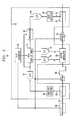
- FIG. 2shows a general block diagram of an adaptive predistortion power amplification system 50 which uses a pilot signal to calibrate predistortion circuitry 52 .
- the predistortion circuitry 52responds to the input signal u n by adjusting the amplitude and/or phase of an input signal u n on a signal path 54 to produce a predistorted signal x n .
- the predistortion circuitry 52adjusts the input signal u n by implementing a predistortion function to compensate for distortion generated by distortion generating circuitry, such as amplifier 55 .
- the predistortion circuitry 52includes a pilot generator 56 which generates a pilot signal, and the pilot signal is placed on the signal path 54 prior to the amplifier 55 .
- the pilot signal(or a signal representative of the pilot signal on the signal path 54 ) is detected by a pilot detector 58 .
- the predistortion circuitry 52calibrates or adjusts the amplitude and/or phase adjustments for the input signal u n .
- the predistortion circuitry 52synchronizes or maps the detected pilot signal with the generated pilot signal and an input signal value. Even though the detected pilot signal is typically very small compared to the input signal, the detected pilot signal can provide phase and/or amplitude response information for the amplifier 55 .
- the predistortion circuitry 52can calibrate or adjust the predistortion function, thereby changing the phase and/or amplitude adjustments made for the input signal value.
- the predistortion functioncan be calibrated for each input signal value.
- an input signal u n on a main signal path 54is provided to the predistortion amplifier system 50 .
- a replica of the input signal u nis coupled off the main signal path 54 onto detection path 65 using coupler 66 , and the input signal envelope is detected using envelope detector 68 .
- the envelope signalis digitized by analog to digital converter (A/D) 70 and used as a pointer for a look-up table 72 , such as a field programmable gate array (FPGA) look-up table, which implements the predistortion function.
- A/Danalog to digital converter
- a look-up table 72such as a field programmable gate array (FPGA) look-up table, which implements the predistortion function.
- the look-up table 72produces values to implement the predistortion function onto the input signal on the signal path 54 .
- the outputs of the lookup tableare passed to respective digital to analog (D/A) converters 74 and 76 .
- a vector modulator 80uses the outputs of the look-up table 74 to modulate the respective phase (P) and amplitude (A) components of the input signal u n on the main signal path 54 , thereby producing the predistorted signal x n such that the distortion produced by amplifier 55 in amplifying the input signal u n is reduced.
- the phase and/or amplitude adjustments needed to distort the input signal according to the predistortion functioncan be calculated by the predistortion circuitry 52 using the predistortion function and given the detected input signal envelope.
- a delay 88delays the input signal on the main signal path 54 .
- the delay 88corresponds to the overall delay of the envelope detector 68 , the A/D 70 , the look-up table 72 and the D/A's 74 and 76 .
- the pilot signalis placed on the signal path 54 prior to the amplifier 55 , and a replica of the pilot signal is coupled off the signal path 54 by coupler 92 and provided to a pilot detection or feedback path 93 after the amplifier 55 .
- the pilot detector 58detects the pilot signal, and the detected pilot signal measurement(s) is provided to the predistortion circuitry 52 .
- the pilot signalcan be detected by filtering at the pilot signal frequency to allow the pilot signal to pass while attenuating the input signal after which phase and/or amplitude measurement(s) can be produced of the pilot signal to the predistortion circuitry 52 .
- the generated pilot signalcould be a spread spectrum pilot signal which is de-spread on the pilot detection path to raise the pilot signal while lowering the input signal after which the phase and/or amplitude measurement(s) are performed.
- the predistortion circuitry 52includes an analog to digital converter 94 which analog-to-digitally converts the detected pilot signal measurement(s).
- the digital representation of the detected pilot signal measurement(s)is provided to processing circuitry 96 .
- the processing circuitry 96also receives the pointers to the look-up table 72 which represent the detected input signal envelopes.
- the processing circuitry 96synchronizes or maps the detected pilot signal measurement(s) with the generated pilot signal and/or the input signal envelope and performs a waveform comparison of the generated pilot signal and the output pilot signal given the detected input signal envelope. In doing so, the processing circuitry 96 can determine a phase and amplitude response for the amplifier and/or the phase and/or amplitude distortion generated by the amplifier 55 .
- the processing circuitry 96can calibrate the look-up table 72 , for example by updating the amplifier characteristics polynomial and/or the predistortion function and calculating and loading the updated values into the table.
- the calibration of the look-up table 72can be done for an input signal value at a time and/or without approximations across an input signal value range as is usually done.
- the calibrationcan also be done with actual input or traffic signals running through the amplifier 55 , allowing the amplifier 55 to be auto-calibrated without disturbing the traffic signals.
- the predistortion functioncan be generated by first estimating the characteristics of the amplifier 55 , for example by finding the coefficients which minimize the error between the expected pilot signal output of the amplifier 55 and the pilot signal output of the amplifier 55 given the input signal u n or x n . After the amplifier characteristics are determined, the predistortion function can be determined and/or updated by finding the inverse to the amplifier characteristics function. Alternatively, the predistortion function can be directly determined using the known pilot signal and the amplifier output pilot signal, for example by minimizing the error between the actual generated pilot signal and the amplifier output pilot signal.
- the pilot signalcan be coupled onto the signal path 64 by a coupler 92 or added to the values in the look-up table 72 .
- the output of the look-up table 72is not only the amplitude and/or phase adjustment values resulting from the predistortion function or table implemented in the look-up table 72 but also the digital representation of the pilot signal which is added to the output of the look-up table 72 .
- the pilot signal valuescan be added to the values output from the look-up table to provide the pilot signal on the main signal path by modulating or adding the pilot signal onto the adjustment values, thereby reducing the circuitry required to inject the pilot signal onto the main signal path 54 .
- the pilot signalcould be directly added to the input signal, for example at baseband in the digital domain.
- the predistortion system and methoduses a pilot signal to determine the predistortion function (which can include updating, calibrating or changing the predistortion function, coefficients and/or adjustment values for a given signal value(s) or range of values). Because the generated pilot signal is known, the calibration of the predistortion generation may be more readily achieved for different signal values. Typically, the input signal envelope is detected prior to the amplifier and the corresponding amplified signal is detected on a feedback path. As would be understood by one of skill in the art, the predistortion function is calibrated based on these measurements, but basing the calibrations or adjustments on a changing input signal and the resulting amplified signal may be more difficult. Instead, a constant or known pilot signal can be used along with the changing signal values to more readily detect or determine the amplitude and/or phase distortion introduced by the amplifier for changing signal values, thereby improving the ability to calibrate the predistortion applied to the signal values.
- a pilot signalcan be used along with the changing signal values to more readily
- the predistortion circuitry 52can be comprised of different components which determine the predistortion function (including updating, calibrating, compensating or changing in any way the manner in which the signal(s) on the main signal path 54 is predistorted for given signal value(s)) based on a measurement or detection of a pilot signal which is input into the main signal path 54 prior to the amplifier 55 and detected or measured after the amplifier 55 .
- phase, amplitude and/or signal envelope detectorscan be located on the path 94 to perform those or other measurements of the input signal and/or the pilot signal prior to the amplifier 55 on the path 54
- phase, amplitude and/or envelope detectorscan be located on the feedback path 93 to perform those and other measurements on the pilot signal and/or the signal output from the amplifier 55 .
- Samples or replicas of signals or pilot signal at different points on the signal path 54 prior to and/or after the amplifier 55can be provided to the predistortion circuitry 52 , including but not limited to the input signal u n , the predistorted signal x n the pilot signal prior to the amplifier 55 and/or the amplified signal or pilot signal.
- the embodiment of the predistortion systemhas been described as being used with a particular adaptive predistortion architecture, but the predistortion system can be used in any predistortion system which is used to reduce the distortion generated by any distortion generating circuitry which acts on a signal.
- different types of pilot signalscan be used by the predistortion system, such as a continuous wave (CW) pilot, a spread spectrum pilot, a modulated pilot, a pilot of varying frequency, or a pilot having different frequency components.
- the predistortion systemcan be positioned in or in addition to a feed forward, or other linearization or efficiency-improving techniques.
- the predistortion calibration system and portions thereofcan be implemented at, baseband, intermediate frequency (IF) and/or radio frequency (RF) in the digital and/or analog domain.
- the predistortion systemhas been further described as a particular configuration, but it should be understood that the calibration system and portions thereof can be implemented in application specific integrated circuits, software-driven processing circuitry, firmware, programmable logic devices, hardware and/or other arrangements of discrete components as would be understood by one of ordinary skill in the art with the benefit of this disclosure. What has been described is merely illustrative of the application of the principles of the present invention. Those skilled in the art will readily recognize that these and various other modifications, arrangements and methods can be made to the present invention without strictly following the exemplary applications illustrated and described herein and without departing from the spirit and scope of the present invention.
Landscapes
- Physics & Mathematics (AREA)
- Nonlinear Science (AREA)
- Engineering & Computer Science (AREA)
- Power Engineering (AREA)
- Amplifiers (AREA)
Abstract
Description
1. Field of the Invention
This invention relates to communications, and, more particularly, to a system and method for reducing distortion using predistortion.
2. Description of Related Art
An ideal power amplifier amplifies an input signal with no waveshape alteration. The ideal power amplifier is therefore characterized as having a transfer function (input signal vs. output signal) which is linear with no transfer function discontinuities. In practice, however, a power amplifier has a transfer function with nonlinear and “linear” regions. Whether the power amplifier is operating in a linear or nonlinear region depends in part on the amplitude of the input signal. For the power amplifier to achieve as near to linear operation as possible, the power amplifier is designed to operate within its linear region given the range of possible input signal amplitudes. If the input signal has an amplitude which causes the power amplifier to operate outside the linear region, the power amplifier introduces nonlinear components or distortion to the signal. When the input signal possesses amplitudes which cause the amplifier to compress, to saturate (no appreciable increase in output amplitude with an increase in input amplitude) or to shut-off (no appreciable decrease in output amplitude with a decrease in input amplitude), the output signal is clipped or distorted in a nonlinear fashion. Generally, an amplifier is characterized as having a clipping threshold, and input signals having amplitudes beyond the clipping threshold are clipped at the amplifier output. In addition to distorting the signal, the clipping or nonlinear distortion of the input signal, generates spectral regrowth or adjacent channel power (ACP) that can interfere with an adjacent frequency.
In wireless communications systems, high power amplification of signals for transmission are commonly encountered with very large peak to average power ratios (PAR). For example, in a time division multiple access (TDMA) system, such as Global System for Mobile Communications (GSM) or North American TDMA, when multiple carrier signals are combined for amplification with a power amplifier, the resulting PAR is about 9-10 dB for a large number of carriers. In a code division multiple access (CDMA) system, a single loaded 1.25 Mhz wide carrier can typically have a PAR of 11.3 dB. For orthogonal frequency division multiplexing (OFDM), multicarrier signals can have a PAR of up to 20 dB. These signals have to be amplified fairly linearly to avoid generating ACP.
Unfortunately, efficiency of the base station amplifier is inversely related to its linearity. To achieve a high degree of linearity, the amplifiers are biased to operate in the class A or “slight” class AB (meaning class AB operation that is closer to class A than to class B). Maximum AC to DC efficiency achievable for class A operation is 50%, whereas that of a class AB amplifier is between 50 and 78.5% (the latter representing the maximum efficiency of a class B amplifier). The closer the particular class AB operation is to class A, the lower the maximum efficiency. For amplifiers employing field effect transistors, the class of operation is set in accordance with the gate voltage applied, which controls the quiescent (idle) drain current. For class A operation, the gate voltage is set so that the idle drain current is approximately in the middle of the range between cutoff and saturation. Class B amplifiers are biased near cutoff, resulting in a rectified drain current waveform. Class AB amplifiers are biased in between the bias points of classes A and B.
Typically, strict linearity requirements in modern wireless communication systems dictate the use of the relatively inefficient class A or slight class AB modes. As a result, significant DC power is dissipated by the amplifiers, thereby generating heat which must be controlled to avoid degrading amplifier performance and reliability. Hence, the use of elaborate heat sinks and fans become a necessary by-product of the high linearity system. Naturally, these measures add to the cost, size and weight of the base station equipment. As the number of wireless communications users continues to grow, so do the number of base stations and the need to keep them small, light and inexpensive. Thus, a great deal of research has focused on the quest to improve amplifier efficiency in these and other systems.
Various linearization methods are used to enable the use of more cost-effective and more power efficient amplifiers while maintaining an acceptable level of linearity. Feed-forward correction is routinely deployed in modern amplifiers to improve the linearity of the main amplifier with various input patterns. The essence of the feed-forward correction is to isolate the distortion generated by the main amplifier on a feed forward path. The distortion is provided to a correction amplifier on the feed forward path which amplifies the distortion. The distortion on the feed forward path is combined with the distortion on the main signal path to cancel the distortion on the main signal path.
Predistortion techniques are commonly used to improve the performance of RF power amplifiers. Predistortion techniques distort the input signal prior to amplification by taking into account the transfer function characteristics for the amplifier. The desired amplified signal is achieved from the predistorted input signal by intentionally distorting the signal before the amplifier, so the non-linearity of the amplifier can be compensated.
FIG. 1 shows a block diagram of an adaptive poweramplifier predistortion system 10. The baseband digital input signal unon amain signal path 12 is input into the predistortion function14 (A(.)) to produce a predistorted output xnwhere n is the time index. After digital to analog conversion by digital to analog (D/A)converter 16, the resulting baseband analog signal is frequency up-converted in an up-conversion process 18 to radio frequency (RF). The analog RF signals are amplified bypower amplifier 20 for transmission over theair using antenna 22. A replica of the amplified analog RF signals is coupled off themain signal path 12 onto apredistortion feedback path 24. The amplified analog RF signals on thepredistortion feedback path 24 are down-converted by a down-conversion process 26.
The down-converted analog signals on thepredistortion feedback path 24 are provided to an analog to digital (A/D)converter 28 for conversion into the digital domain. The resulting digital signal, which represents the output of theamplifier 20, is provided to an amplifiercharacteristics estimation block 30 along with the digital baseband signal xnwhich represents the corresponding input to theamplifier 20. Given the digital signals xnprior to amplification and the digital signals ynresulting from the amplification of the analog- and frequency-converted versions of the digital signals xn, the amplifiercharacteristics estimation block 30 can determine the characteristics or model function of theamplifier 20. Once the characteristics function of theamplifier 20 is estimated, apredistortion calculation process 34 determines the predistortion function as the inverse of the amplifier characteristics function, and the predistortion function14 (A(.)) applied to the input signal unis updated based on thepredistortion calculation process 34.
Thus, predistortion techniques require prior understanding of the response of the amplifier. Both pure digital and RF/digital predistortion implementations use polynomial approximation to predict the amplitude and phase distortion of the RF amplifier from which the predistortion function is determined. Alternatively, the predistortion function can be directly determined using inputs and outputs of theamplifier 20. In any event, adaptive predistortion systems monitor the signals prior to and after the power amplifier to determine the predistortion function, for example by updating the coefficients of the amplifier characteristics polynomial and calculating the inverse of the amplifier characteristics polynomial. Improving the detection of signals prior to and after the amplifier can improve the determination of the predistortion function, thereby improving the performance of the predistortion system. For example, the improved detection of signals prior to and after the amplifier can improve the determination of the amplifier characteristics function from which a better inverse function can be obtained. In a standard predistortion system implementation, the input signal envelope is detected and used as a pointer to a look-up table which implements the predistortion function. The values of the look-up table are passed to a digital to analog (D/A) converter that modulates or predistorts the input signal to compensate for the distortion of the amplifier. Improvement in amplifier performance is constrained by how well the signals used in the determination of the predistortion system are detected for different input signal levels.
The present invention is a predistortion system which uses a pilot signal to determine a predistortion function which is used to produce amplitude and/or phase adjustment(s) of an input signal on a signal path. Rather than simply detecting the input signal envelope before and after distortion generating circuitry, such as an amplifier, a pilot signal is provided on the signal path prior to the distortion generating circuitry. After the distortion generating circuitry, the pilot signal is detected. The predistortion system can determine the predistortion function by using the generated pilot signal and the detected pilot signal, for example, to provide improved characterization of the amplifier amplitude and/or phase response or to directly improve the determination of the predistortion function. In certain embodiments, the predistortion function is implemented using a look-up table to produce the amplitude and/or phase adjustment values, and the pilot signal is produced on the signal path by adding the pilot signal to the amplitude and/or phase adjustment values of the look-up table.
Other aspects and advantages of the present invention may become apparent upon reading the following detailed description and upon reference to the drawings in which:
FIG. 1 shows a general block diagram of a typical adaptive power amplifier predistortion system; and
FIG. 2 shows a general block diagram of an adaptive predistortion system according to principles of the present invention.
An illustrative embodiment of an adaptive predistortion amplifier system is described below according to principles of the present invention which uses a pilot signal to determine the predistortion function. Determining the predistortion function can include determining a new predistortion function or model, calibrating, updating or making any changes or adjustments to a current predistortion function or model or coefficients thereof, and/or making any changes or adjustments to phase and/or amplitude adjustments made to predistort the signal on the signal path from which distortion is to be reduced.
FIG. 2 shows a general block diagram of an adaptive predistortionpower amplification system 50 which uses a pilot signal to calibratepredistortion circuitry 52. In this embodiment, thepredistortion circuitry 52 responds to the input signal unby adjusting the amplitude and/or phase of an input signal unon asignal path 54 to produce a predistorted signal xn. Thepredistortion circuitry 52 adjusts the input signal unby implementing a predistortion function to compensate for distortion generated by distortion generating circuitry, such asamplifier 55.
Thepredistortion circuitry 52 includes apilot generator 56 which generates a pilot signal, and the pilot signal is placed on thesignal path 54 prior to theamplifier 55. After theamplifier 55, the pilot signal (or a signal representative of the pilot signal on the signal path54) is detected by apilot detector 58. In response to the detected pilot signal, thepredistortion circuitry 52 calibrates or adjusts the amplitude and/or phase adjustments for the input signal un. For example, thepredistortion circuitry 52 synchronizes or maps the detected pilot signal with the generated pilot signal and an input signal value. Even though the detected pilot signal is typically very small compared to the input signal, the detected pilot signal can provide phase and/or amplitude response information for theamplifier 55. Using this information, thepredistortion circuitry 52 can calibrate or adjust the predistortion function, thereby changing the phase and/or amplitude adjustments made for the input signal value. Depending on the embodiment, the predistortion function can be calibrated for each input signal value.
In this embodiment, an input signal unon amain signal path 54 is provided to thepredistortion amplifier system 50. A replica of the input signal unis coupled off themain signal path 54 ontodetection path 65 using coupler66, and the input signal envelope is detected usingenvelope detector 68. The envelope signal is digitized by analog to digital converter (A/D)70 and used as a pointer for a look-up table72, such as a field programmable gate array (FPGA) look-up table, which implements the predistortion function. In response to the detected input signal envelope, the look-up table72 produces values to implement the predistortion function onto the input signal on thesignal path 54.
For example, the outputs of the lookup table are passed to respective digital to analog (D/A)converters vector modulator 80 uses the outputs of the look-up table74 to modulate the respective phase (P) and amplitude (A) components of the input signal unon themain signal path 54, thereby producing the predistorted signal xnsuch that the distortion produced byamplifier 55 in amplifying the input signal unis reduced. Alternatively, the phase and/or amplitude adjustments needed to distort the input signal according to the predistortion function can be calculated by thepredistortion circuitry 52 using the predistortion function and given the detected input signal envelope. To align the detected envelope of the input signal with the modulation of the corresponding portion of the input signal unon thesignal path 54, adelay 88 delays the input signal on themain signal path 54. In this embodiment, thedelay 88 corresponds to the overall delay of theenvelope detector 68, the A/D 70, the look-up table72 and the D/A's74 and76.
The pilot signal is placed on thesignal path 54 prior to theamplifier 55, and a replica of the pilot signal is coupled off thesignal path 54 bycoupler 92 and provided to a pilot detection orfeedback path 93 after theamplifier 55. On thepilot detection path 93, thepilot detector 58 detects the pilot signal, and the detected pilot signal measurement(s) is provided to thepredistortion circuitry 52. The pilot signal can be detected by filtering at the pilot signal frequency to allow the pilot signal to pass while attenuating the input signal after which phase and/or amplitude measurement(s) can be produced of the pilot signal to thepredistortion circuitry 52. Depending on the embodiment, the generated pilot signal could be a spread spectrum pilot signal which is de-spread on the pilot detection path to raise the pilot signal while lowering the input signal after which the phase and/or amplitude measurement(s) are performed.
In this embodiment, thepredistortion circuitry 52 includes an analog todigital converter 94 which analog-to-digitally converts the detected pilot signal measurement(s). The digital representation of the detected pilot signal measurement(s) is provided toprocessing circuitry 96. Theprocessing circuitry 96 also receives the pointers to the look-up table72 which represent the detected input signal envelopes. Theprocessing circuitry 96 synchronizes or maps the detected pilot signal measurement(s) with the generated pilot signal and/or the input signal envelope and performs a waveform comparison of the generated pilot signal and the output pilot signal given the detected input signal envelope. In doing so, theprocessing circuitry 96 can determine a phase and amplitude response for the amplifier and/or the phase and/or amplitude distortion generated by theamplifier 55. Using this amplitude and/or phase distortion or response information, theprocessing circuitry 96 can calibrate the look-up table72, for example by updating the amplifier characteristics polynomial and/or the predistortion function and calculating and loading the updated values into the table. Depending on the embodiment, the calibration of the look-up table72 can be done for an input signal value at a time and/or without approximations across an input signal value range as is usually done. The calibration can also be done with actual input or traffic signals running through theamplifier 55, allowing theamplifier 55 to be auto-calibrated without disturbing the traffic signals.
Depending on the embodiment, the predistortion function can be generated by first estimating the characteristics of theamplifier 55, for example by finding the coefficients which minimize the error between the expected pilot signal output of theamplifier 55 and the pilot signal output of theamplifier 55 given the input signal unor xn. After the amplifier characteristics are determined, the predistortion function can be determined and/or updated by finding the inverse to the amplifier characteristics function. Alternatively, the predistortion function can be directly determined using the known pilot signal and the amplifier output pilot signal, for example by minimizing the error between the actual generated pilot signal and the amplifier output pilot signal.
Depending on the embodiment, the pilot signal can be coupled onto the signal path64 by acoupler 92 or added to the values in the look-up table72. In this embodiment and in accordance with certain principles of the present invention, the output of the look-up table72 is not only the amplitude and/or phase adjustment values resulting from the predistortion function or table implemented in the look-up table72 but also the digital representation of the pilot signal which is added to the output of the look-up table72. As such, the pilot signal values can be added to the values output from the look-up table to provide the pilot signal on the main signal path by modulating or adding the pilot signal onto the adjustment values, thereby reducing the circuitry required to inject the pilot signal onto themain signal path 54. Alternatively, the pilot signal could be directly added to the input signal, for example at baseband in the digital domain.
Thus, the predistortion system and method uses a pilot signal to determine the predistortion function (which can include updating, calibrating or changing the predistortion function, coefficients and/or adjustment values for a given signal value(s) or range of values). Because the generated pilot signal is known, the calibration of the predistortion generation may be more readily achieved for different signal values. Typically, the input signal envelope is detected prior to the amplifier and the corresponding amplified signal is detected on a feedback path. As would be understood by one of skill in the art, the predistortion function is calibrated based on these measurements, but basing the calibrations or adjustments on a changing input signal and the resulting amplified signal may be more difficult. Instead, a constant or known pilot signal can be used along with the changing signal values to more readily detect or determine the amplitude and/or phase distortion introduced by the amplifier for changing signal values, thereby improving the ability to calibrate the predistortion applied to the signal values.
In addition to the embodiment described above, alternative configurations of the predistortion calibration system according to the principles of the present invention are possible which omit and/or add components and/or use variations or portions of the described system. Depending on the embodiment, thepredistortion circuitry 52 can be comprised of different components which determine the predistortion function (including updating, calibrating, compensating or changing in any way the manner in which the signal(s) on themain signal path 54 is predistorted for given signal value(s)) based on a measurement or detection of a pilot signal which is input into themain signal path 54 prior to theamplifier 55 and detected or measured after theamplifier 55. Additionally, phase, amplitude and/or signal envelope detectors can be located on thepath 94 to perform those or other measurements of the input signal and/or the pilot signal prior to theamplifier 55 on thepath 54, and phase, amplitude and/or envelope detectors can be located on thefeedback path 93 to perform those and other measurements on the pilot signal and/or the signal output from theamplifier 55. Samples or replicas of signals or pilot signal at different points on thesignal path 54 prior to and/or after theamplifier 55 can be provided to thepredistortion circuitry 52, including but not limited to the input signal un, the predistorted signal xnthe pilot signal prior to theamplifier 55 and/or the amplified signal or pilot signal.
The embodiment of the predistortion system has been described as being used with a particular adaptive predistortion architecture, but the predistortion system can be used in any predistortion system which is used to reduce the distortion generated by any distortion generating circuitry which acts on a signal. Moreover, different types of pilot signals can be used by the predistortion system, such as a continuous wave (CW) pilot, a spread spectrum pilot, a modulated pilot, a pilot of varying frequency, or a pilot having different frequency components. Depending on the application, the predistortion system can be positioned in or in addition to a feed forward, or other linearization or efficiency-improving techniques. The predistortion calibration system and portions thereof can be implemented at, baseband, intermediate frequency (IF) and/or radio frequency (RF) in the digital and/or analog domain.
The predistortion system has been further described as a particular configuration, but it should be understood that the calibration system and portions thereof can be implemented in application specific integrated circuits, software-driven processing circuitry, firmware, programmable logic devices, hardware and/or other arrangements of discrete components as would be understood by one of ordinary skill in the art with the benefit of this disclosure. What has been described is merely illustrative of the application of the principles of the present invention. Those skilled in the art will readily recognize that these and various other modifications, arrangements and methods can be made to the present invention without strictly following the exemplary applications illustrated and described herein and without departing from the spirit and scope of the present invention.
Claims (7)
1. A method of producing predistortion, said method comprising:
producing a pilot signal on a signal path prior to a distortion generating circuit;
detecting said pilot signal after said distortion generating circuit;
determining a predistortion function in response to said detected pilot signal; and
determining for an input signal value an amplitude and/or phase adjustment as a function of an input signal value, said generated pilot signal and said detected pilot signal.
2. The method ofclaim 1 further including:
distorting a signal on said signal path using said predistortion function to produce a predistorted signal on said signal path for said distortion generating circuit.
3. The method ofclaim 2 wherein said step of distorting includes:
adjusting amplitude and/or phase of said signal on said signal path using said predistortion function.
4. The method ofclaim 3 comprising:
determining amplitude and/or phase adjustments for input signal values using said predistortion function.
5. The method ofclaim 1 wherein said step of determining includes:
updating coefficients of an amplifier characteristics function;
calculating an inverse to said amplifier characteristics function as said predistortion function.
6. The method ofclaim 1 comprising mapping said detected pilot signal with a corresponding input signal value.
7. The method ofclaim 1 comprising the step of:
generating a pilot signal.
Priority Applications (1)
| Application Number | Priority Date | Filing Date | Title |
|---|---|---|---|
| US09/904,611US6496062B1 (en) | 2001-07-13 | 2001-07-13 | Predistortion system and method using a pilot signal |
Applications Claiming Priority (1)
| Application Number | Priority Date | Filing Date | Title |
|---|---|---|---|
| US09/904,611US6496062B1 (en) | 2001-07-13 | 2001-07-13 | Predistortion system and method using a pilot signal |
Publications (1)
| Publication Number | Publication Date |
|---|---|
| US6496062B1true US6496062B1 (en) | 2002-12-17 |
Family
ID=25419438
Family Applications (1)
| Application Number | Title | Priority Date | Filing Date |
|---|---|---|---|
| US09/904,611Expired - LifetimeUS6496062B1 (en) | 2001-07-13 | 2001-07-13 | Predistortion system and method using a pilot signal |
Country Status (1)
| Country | Link |
|---|---|
| US (1) | US6496062B1 (en) |
Cited By (32)
| Publication number | Priority date | Publication date | Assignee | Title |
|---|---|---|---|---|
| US20020193087A1 (en)* | 2001-06-07 | 2002-12-19 | Jaehyeong Kim | Method and apparatus for modeling and estimating the characteristics of a power amplifier |
| US20030179831A1 (en)* | 2002-03-21 | 2003-09-25 | Deepnarayan Gupta | Power amplifier linearization |
| US20030223509A1 (en)* | 2002-05-31 | 2003-12-04 | Zhengxiang Ma | system and method for predistorting a signal to reduce out-of-band error |
| US20040032912A1 (en)* | 2002-08-16 | 2004-02-19 | Andrew Corporation | Linearization of amplifiers using baseband detection and non-baseband pre-distortion |
| US20040251961A1 (en)* | 2003-05-07 | 2004-12-16 | Braithwaite Richard Neil | Feed forward amplifier employing positive feedback pilot generation |
| US20040252784A1 (en)* | 2003-06-13 | 2004-12-16 | Walter Honcharenko | Coefficient estimation method and apparatus |
| US20050156662A1 (en)* | 2004-01-16 | 2005-07-21 | Arun Raghupathy | Amplifier predistortion and autocalibration method and apparatus |
| US7184723B2 (en) | 2004-10-22 | 2007-02-27 | Parkervision, Inc. | Systems and methods for vector power amplification |
| US20070076814A1 (en)* | 2003-09-25 | 2007-04-05 | Matsushita Electric Industrial Co., Ltd. | Amplifier circuit and amplifying method |
| US20070222513A1 (en)* | 2006-03-09 | 2007-09-27 | Kossor Michael G | Apparatus and method for processing of amplifier linearization signals |
| US7355470B2 (en) | 2006-04-24 | 2008-04-08 | Parkervision, Inc. | Systems and methods of RF power transmission, modulation, and amplification, including embodiments for amplifier class transitioning |
| US7620129B2 (en) | 2007-01-16 | 2009-11-17 | Parkervision, Inc. | RF power transmission, modulation, and amplification, including embodiments for generating vector modulation control signals |
| US20100248658A1 (en)* | 2007-10-18 | 2010-09-30 | Freescale Semiconductor, Inc. | Method and system of adaptive predistortion of a wireless transmitter |
| RU2406219C2 (en)* | 2004-07-06 | 2010-12-10 | Нокиа Сименс Нетворкс Гмбх Унд Ко. Кг | Method and device for linearisation of power amplifier characteristic |
| US7885682B2 (en) | 2006-04-24 | 2011-02-08 | Parkervision, Inc. | Systems and methods of RF power transmission, modulation, and amplification, including architectural embodiments of same |
| US7911272B2 (en) | 2007-06-19 | 2011-03-22 | Parkervision, Inc. | Systems and methods of RF power transmission, modulation, and amplification, including blended control embodiments |
| EP2341613A1 (en)* | 2009-12-29 | 2011-07-06 | Nera Networks As | A detector for nonlinearities |
| US8013675B2 (en) | 2007-06-19 | 2011-09-06 | Parkervision, Inc. | Combiner-less multiple input single output (MISO) amplification with blended control |
| US8031804B2 (en) | 2006-04-24 | 2011-10-04 | Parkervision, Inc. | Systems and methods of RF tower transmission, modulation, and amplification, including embodiments for compensating for waveform distortion |
| US20120133434A1 (en)* | 2010-11-25 | 2012-05-31 | Samsung Electronics Co., Ltd. | Method and apparatus for improving digital pre-distortion performance |
| US8315336B2 (en) | 2007-05-18 | 2012-11-20 | Parkervision, Inc. | Systems and methods of RF power transmission, modulation, and amplification, including a switching stage embodiment |
| US8334722B2 (en) | 2007-06-28 | 2012-12-18 | Parkervision, Inc. | Systems and methods of RF power transmission, modulation and amplification |
| US8755454B2 (en) | 2011-06-02 | 2014-06-17 | Parkervision, Inc. | Antenna control |
| US20140187183A1 (en)* | 2012-12-28 | 2014-07-03 | Fujitsu Limited | Transmission signal power control device and communication apparatus |
| US9106316B2 (en) | 2005-10-24 | 2015-08-11 | Parkervision, Inc. | Systems and methods of RF power transmission, modulation, and amplification |
| US9595983B1 (en)* | 2016-03-07 | 2017-03-14 | The United States Of America As Represented By The Secretary Of The Air Force | Method and apparatus for digital predistortion of ultra wideband radio frequency upconverters |
| US9608677B2 (en) | 2005-10-24 | 2017-03-28 | Parker Vision, Inc | Systems and methods of RF power transmission, modulation, and amplification |
| US9813085B1 (en)* | 2016-09-23 | 2017-11-07 | Qualcomm Incorporated | Closed loop digital pre-distortion |
| US9906191B1 (en) | 2010-08-02 | 2018-02-27 | Hypres, Inc. | Superconducting multi-bit digital mixer |
| US10278131B2 (en) | 2013-09-17 | 2019-04-30 | Parkervision, Inc. | Method, apparatus and system for rendering an information bearing function of time |
| US11239804B2 (en)* | 2019-05-14 | 2022-02-01 | Empower RF Systems, Inc. | Systems and methods for controlling a power amplifier output |
| CN114039619A (en)* | 2021-09-28 | 2022-02-11 | 三维通信股份有限公司 | Zero intermediate frequency radio frequency front end circuit, system, radio frequency unit protection method and medium |
Citations (2)
| Publication number | Priority date | Publication date | Assignee | Title |
|---|---|---|---|---|
| US5266906A (en)* | 1991-10-29 | 1993-11-30 | Nec Corporation | Linear amplifier performing distortion compensation control |
| US5963090A (en)* | 1996-11-13 | 1999-10-05 | Nec Corporation | Automatic predistortion adjusting circuit having stable non-linear characteristics regardless of input signal frequency |
- 2001
- 2001-07-13USUS09/904,611patent/US6496062B1/ennot_activeExpired - Lifetime
Patent Citations (2)
| Publication number | Priority date | Publication date | Assignee | Title |
|---|---|---|---|---|
| US5266906A (en)* | 1991-10-29 | 1993-11-30 | Nec Corporation | Linear amplifier performing distortion compensation control |
| US5963090A (en)* | 1996-11-13 | 1999-10-05 | Nec Corporation | Automatic predistortion adjusting circuit having stable non-linear characteristics regardless of input signal frequency |
Cited By (97)
| Publication number | Priority date | Publication date | Assignee | Title |
|---|---|---|---|---|
| US20020193087A1 (en)* | 2001-06-07 | 2002-12-19 | Jaehyeong Kim | Method and apparatus for modeling and estimating the characteristics of a power amplifier |
| US6903604B2 (en)* | 2001-06-07 | 2005-06-07 | Lucent Technologies Inc. | Method and apparatus for modeling and estimating the characteristics of a power amplifier |
| US20030179831A1 (en)* | 2002-03-21 | 2003-09-25 | Deepnarayan Gupta | Power amplifier linearization |
| US7313199B2 (en)* | 2002-03-21 | 2007-12-25 | Hypres, Inc. | Power amplifier linearization |
| US20030223509A1 (en)* | 2002-05-31 | 2003-12-04 | Zhengxiang Ma | system and method for predistorting a signal to reduce out-of-band error |
| US7194043B2 (en)* | 2002-05-31 | 2007-03-20 | Lucent Technologies Inc. | System and method for predistorting a signal to reduce out-of-band error |
| US20040032912A1 (en)* | 2002-08-16 | 2004-02-19 | Andrew Corporation | Linearization of amplifiers using baseband detection and non-baseband pre-distortion |
| US7321635B2 (en) | 2002-08-16 | 2008-01-22 | Andrew Corporation | Linearization of amplifiers using baseband detection and non-baseband pre-distortion |
| US7123086B2 (en) | 2003-05-07 | 2006-10-17 | Powerwave Technologies, Inc. | Feed forward amplifier employing positive feedback pilot generation |
| US20040251961A1 (en)* | 2003-05-07 | 2004-12-16 | Braithwaite Richard Neil | Feed forward amplifier employing positive feedback pilot generation |
| US20040252784A1 (en)* | 2003-06-13 | 2004-12-16 | Walter Honcharenko | Coefficient estimation method and apparatus |
| US7720171B2 (en)* | 2003-06-13 | 2010-05-18 | Alcatel-Lucent Usa Inc. | Coefficient estimation method and apparatus |
| US20070076814A1 (en)* | 2003-09-25 | 2007-04-05 | Matsushita Electric Industrial Co., Ltd. | Amplifier circuit and amplifying method |
| US7684513B2 (en)* | 2003-09-25 | 2010-03-23 | Panasonic Corporation | Amplifier circuit and amplifying method |
| RU2336628C2 (en)* | 2004-01-16 | 2008-10-20 | Квэлкомм Инкорпорейтед | Device and method of amplifier pre-distortion and autocalibration |
| US20050156662A1 (en)* | 2004-01-16 | 2005-07-21 | Arun Raghupathy | Amplifier predistortion and autocalibration method and apparatus |
| US7915954B2 (en) | 2004-01-16 | 2011-03-29 | Qualcomm, Incorporated | Amplifier predistortion and autocalibration method and apparatus |
| RU2406219C2 (en)* | 2004-07-06 | 2010-12-10 | Нокиа Сименс Нетворкс Гмбх Унд Ко. Кг | Method and device for linearisation of power amplifier characteristic |
| US7647030B2 (en) | 2004-10-22 | 2010-01-12 | Parkervision, Inc. | Multiple input single output (MISO) amplifier with circuit branch output tracking |
| US8626093B2 (en) | 2004-10-22 | 2014-01-07 | Parkervision, Inc. | RF power transmission, modulation, and amplification embodiments |
| US8280321B2 (en) | 2004-10-22 | 2012-10-02 | Parkervision, Inc. | Systems and methods of RF power transmission, modulation, and amplification, including Cartesian-Polar-Cartesian-Polar (CPCP) embodiments |
| US8406711B2 (en) | 2004-10-22 | 2013-03-26 | Parkervision, Inc. | Systems and methods of RF power transmission, modulation, and amplification, including a Cartesian-Polar-Cartesian-Polar (CPCP) embodiment |
| US7466760B2 (en) | 2004-10-22 | 2008-12-16 | Parkervision, Inc. | Systems and methods of RF power transmission, modulation, and amplification, including transfer function embodiments |
| US7526261B2 (en) | 2004-10-22 | 2009-04-28 | Parkervision, Inc. | RF power transmission, modulation, and amplification, including cartesian 4-branch embodiments |
| US8233858B2 (en) | 2004-10-22 | 2012-07-31 | Parkervision, Inc. | RF power transmission, modulation, and amplification embodiments, including control circuitry for controlling power amplifier output stages |
| US7639072B2 (en) | 2004-10-22 | 2009-12-29 | Parkervision, Inc. | Controlling a power amplifier to transition among amplifier operational classes according to at least an output signal waveform trajectory |
| US8351870B2 (en) | 2004-10-22 | 2013-01-08 | Parkervision, Inc. | Systems and methods of RF power transmission, modulation, and amplification, including cartesian 4-branch embodiments |
| US7672650B2 (en) | 2004-10-22 | 2010-03-02 | Parkervision, Inc. | Systems and methods of RF power transmission, modulation, and amplification, including multiple input single output (MISO) amplifier embodiments comprising harmonic control circuitry |
| US8428527B2 (en) | 2004-10-22 | 2013-04-23 | Parkervision, Inc. | RF power transmission, modulation, and amplification, including direct cartesian 2-branch embodiments |
| US9768733B2 (en) | 2004-10-22 | 2017-09-19 | Parker Vision, Inc. | Multiple input single output device with vector signal and bias signal inputs |
| US9197163B2 (en) | 2004-10-22 | 2015-11-24 | Parkvision, Inc. | Systems, and methods of RF power transmission, modulation, and amplification, including embodiments for output stage protection |
| US9197164B2 (en) | 2004-10-22 | 2015-11-24 | Parkervision, Inc. | RF power transmission, modulation, and amplification, including direct cartesian 2-branch embodiments |
| US7835709B2 (en) | 2004-10-22 | 2010-11-16 | Parkervision, Inc. | RF power transmission, modulation, and amplification using multiple input single output (MISO) amplifiers to process phase angle and magnitude information |
| US7844235B2 (en) | 2004-10-22 | 2010-11-30 | Parkervision, Inc. | RF power transmission, modulation, and amplification, including harmonic control embodiments |
| US7327803B2 (en) | 2004-10-22 | 2008-02-05 | Parkervision, Inc. | Systems and methods for vector power amplification |
| US8433264B2 (en) | 2004-10-22 | 2013-04-30 | Parkervision, Inc. | Multiple input single output (MISO) amplifier having multiple transistors whose output voltages substantially equal the amplifier output voltage |
| US9166528B2 (en) | 2004-10-22 | 2015-10-20 | Parkervision, Inc. | RF power transmission, modulation, and amplification embodiments |
| US9143088B2 (en) | 2004-10-22 | 2015-09-22 | Parkervision, Inc. | Control modules |
| US8447248B2 (en) | 2004-10-22 | 2013-05-21 | Parkervision, Inc. | RF power transmission, modulation, and amplification, including power control of multiple input single output (MISO) amplifiers |
| US7184723B2 (en) | 2004-10-22 | 2007-02-27 | Parkervision, Inc. | Systems and methods for vector power amplification |
| US7932776B2 (en) | 2004-10-22 | 2011-04-26 | Parkervision, Inc. | RF power transmission, modulation, and amplification embodiments |
| US8577313B2 (en) | 2004-10-22 | 2013-11-05 | Parkervision, Inc. | Systems and methods of RF power transmission, modulation, and amplification, including output stage protection circuitry |
| US7945224B2 (en) | 2004-10-22 | 2011-05-17 | Parkervision, Inc. | Systems and methods of RF power transmission, modulation, and amplification, including waveform distortion compensation embodiments |
| US8913974B2 (en) | 2004-10-22 | 2014-12-16 | Parkervision, Inc. | RF power transmission, modulation, and amplification, including direct cartesian 2-branch embodiments |
| US8781418B2 (en) | 2004-10-22 | 2014-07-15 | Parkervision, Inc. | Power amplification based on phase angle controlled reference signal and amplitude control signal |
| US8639196B2 (en) | 2004-10-22 | 2014-01-28 | Parkervision, Inc. | Control modules |
| US7421036B2 (en) | 2004-10-22 | 2008-09-02 | Parkervision, Inc. | Systems and methods of RF power transmission, modulation, and amplification, including transfer function embodiments |
| US9094085B2 (en) | 2005-10-24 | 2015-07-28 | Parkervision, Inc. | Control of MISO node |
| US9106316B2 (en) | 2005-10-24 | 2015-08-11 | Parkervision, Inc. | Systems and methods of RF power transmission, modulation, and amplification |
| US9705540B2 (en) | 2005-10-24 | 2017-07-11 | Parker Vision, Inc. | Control of MISO node |
| US9419692B2 (en) | 2005-10-24 | 2016-08-16 | Parkervision, Inc. | Antenna control |
| US9614484B2 (en) | 2005-10-24 | 2017-04-04 | Parkervision, Inc. | Systems and methods of RF power transmission, modulation, and amplification, including control functions to transition an output of a MISO device |
| US9608677B2 (en) | 2005-10-24 | 2017-03-28 | Parker Vision, Inc | Systems and methods of RF power transmission, modulation, and amplification |
| US20070222513A1 (en)* | 2006-03-09 | 2007-09-27 | Kossor Michael G | Apparatus and method for processing of amplifier linearization signals |
| US7856105B2 (en) | 2006-03-09 | 2010-12-21 | Andrew Llc | Apparatus and method for processing of amplifier linearization signals |
| US8036306B2 (en) | 2006-04-24 | 2011-10-11 | Parkervision, Inc. | Systems and methods of RF power transmission, modulation and amplification, including embodiments for compensating for waveform distortion |
| US7949365B2 (en) | 2006-04-24 | 2011-05-24 | Parkervision, Inc. | Systems and methods of RF power transmission, modulation, and amplification, including architectural embodiments of same |
| US7355470B2 (en) | 2006-04-24 | 2008-04-08 | Parkervision, Inc. | Systems and methods of RF power transmission, modulation, and amplification, including embodiments for amplifier class transitioning |
| US7378902B2 (en) | 2006-04-24 | 2008-05-27 | Parkervision, Inc | Systems and methods of RF power transmission, modulation, and amplification, including embodiments for gain and phase control |
| US7414469B2 (en) | 2006-04-24 | 2008-08-19 | Parkervision, Inc. | Systems and methods of RF power transmission, modulation, and amplification, including embodiments for amplifier class transitioning |
| US7423477B2 (en) | 2006-04-24 | 2008-09-09 | Parkervision, Inc. | Systems and methods of RF power transmission, modulation, and amplification, including embodiments for amplifier class transitioning |
| US8059749B2 (en) | 2006-04-24 | 2011-11-15 | Parkervision, Inc. | Systems and methods of RF power transmission, modulation, and amplification, including embodiments for compensating for waveform distortion |
| US8050353B2 (en) | 2006-04-24 | 2011-11-01 | Parkervision, Inc. | Systems and methods of RF power transmission, modulation, and amplification, including embodiments for compensating for waveform distortion |
| US7750733B2 (en) | 2006-04-24 | 2010-07-06 | Parkervision, Inc. | Systems and methods of RF power transmission, modulation, and amplification, including embodiments for extending RF transmission bandwidth |
| US7885682B2 (en) | 2006-04-24 | 2011-02-08 | Parkervision, Inc. | Systems and methods of RF power transmission, modulation, and amplification, including architectural embodiments of same |
| US7929989B2 (en) | 2006-04-24 | 2011-04-19 | Parkervision, Inc. | Systems and methods of RF power transmission, modulation, and amplification, including architectural embodiments of same |
| US8031804B2 (en) | 2006-04-24 | 2011-10-04 | Parkervision, Inc. | Systems and methods of RF tower transmission, modulation, and amplification, including embodiments for compensating for waveform distortion |
| US9106500B2 (en) | 2006-04-24 | 2015-08-11 | Parkervision, Inc. | Systems and methods of RF power transmission, modulation, and amplification, including embodiments for error correction |
| US8026764B2 (en) | 2006-04-24 | 2011-09-27 | Parkervision, Inc. | Generation and amplification of substantially constant envelope signals, including switching an output among a plurality of nodes |
| US7937106B2 (en) | 2006-04-24 | 2011-05-03 | ParkerVision, Inc, | Systems and methods of RF power transmission, modulation, and amplification, including architectural embodiments of same |
| US8913691B2 (en) | 2006-08-24 | 2014-12-16 | Parkervision, Inc. | Controlling output power of multiple-input single-output (MISO) device |
| US7620129B2 (en) | 2007-01-16 | 2009-11-17 | Parkervision, Inc. | RF power transmission, modulation, and amplification, including embodiments for generating vector modulation control signals |
| US8315336B2 (en) | 2007-05-18 | 2012-11-20 | Parkervision, Inc. | Systems and methods of RF power transmission, modulation, and amplification, including a switching stage embodiment |
| US8548093B2 (en) | 2007-05-18 | 2013-10-01 | Parkervision, Inc. | Power amplification based on frequency control signal |
| US7911272B2 (en) | 2007-06-19 | 2011-03-22 | Parkervision, Inc. | Systems and methods of RF power transmission, modulation, and amplification, including blended control embodiments |
| US8766717B2 (en) | 2007-06-19 | 2014-07-01 | Parkervision, Inc. | Systems and methods of RF power transmission, modulation, and amplification, including varying weights of control signals |
| US8410849B2 (en) | 2007-06-19 | 2013-04-02 | Parkervision, Inc. | Systems and methods of RF power transmission, modulation, and amplification, including blended control embodiments |
| US8461924B2 (en) | 2007-06-19 | 2013-06-11 | Parkervision, Inc. | Systems and methods of RF power transmission, modulation, and amplification, including embodiments for controlling a transimpedance node |
| US8013675B2 (en) | 2007-06-19 | 2011-09-06 | Parkervision, Inc. | Combiner-less multiple input single output (MISO) amplification with blended control |
| US8502600B2 (en) | 2007-06-19 | 2013-08-06 | Parkervision, Inc. | Combiner-less multiple input single output (MISO) amplification with blended control |
| US8334722B2 (en) | 2007-06-28 | 2012-12-18 | Parkervision, Inc. | Systems and methods of RF power transmission, modulation and amplification |
| US8884694B2 (en) | 2007-06-28 | 2014-11-11 | Parkervision, Inc. | Systems and methods of RF power transmission, modulation, and amplification |
| US8238849B2 (en)* | 2007-10-18 | 2012-08-07 | Freescale Semiconductor, Inc. | Method and system of adaptive predistortion of a wireless transmitter |
| US20100248658A1 (en)* | 2007-10-18 | 2010-09-30 | Freescale Semiconductor, Inc. | Method and system of adaptive predistortion of a wireless transmitter |
| EP2341613A1 (en)* | 2009-12-29 | 2011-07-06 | Nera Networks As | A detector for nonlinearities |
| US9906191B1 (en) | 2010-08-02 | 2018-02-27 | Hypres, Inc. | Superconducting multi-bit digital mixer |
| US8624670B2 (en)* | 2010-11-25 | 2014-01-07 | Samsung Electronics Co., Ltd | Method and apparatus for improving digital pre-distortion performance |
| US20120133434A1 (en)* | 2010-11-25 | 2012-05-31 | Samsung Electronics Co., Ltd. | Method and apparatus for improving digital pre-distortion performance |
| US8755454B2 (en) | 2011-06-02 | 2014-06-17 | Parkervision, Inc. | Antenna control |
| US9252714B2 (en)* | 2012-12-28 | 2016-02-02 | Fujitsu Limited | Transmission signal power control device and communication apparatus |
| US20140187183A1 (en)* | 2012-12-28 | 2014-07-03 | Fujitsu Limited | Transmission signal power control device and communication apparatus |
| US10278131B2 (en) | 2013-09-17 | 2019-04-30 | Parkervision, Inc. | Method, apparatus and system for rendering an information bearing function of time |
| US9595983B1 (en)* | 2016-03-07 | 2017-03-14 | The United States Of America As Represented By The Secretary Of The Air Force | Method and apparatus for digital predistortion of ultra wideband radio frequency upconverters |
| US9813085B1 (en)* | 2016-09-23 | 2017-11-07 | Qualcomm Incorporated | Closed loop digital pre-distortion |
| US11239804B2 (en)* | 2019-05-14 | 2022-02-01 | Empower RF Systems, Inc. | Systems and methods for controlling a power amplifier output |
| US12283923B2 (en) | 2019-05-14 | 2025-04-22 | Empower RF Systems, Inc. | Systems and methods for controlling a power amplifier output |
| CN114039619A (en)* | 2021-09-28 | 2022-02-11 | 三维通信股份有限公司 | Zero intermediate frequency radio frequency front end circuit, system, radio frequency unit protection method and medium |
Similar Documents
| Publication | Publication Date | Title |
|---|---|---|
| US6496062B1 (en) | Predistortion system and method using a pilot signal | |
| EP1292019B1 (en) | Multiple stage and/or nested predistortion system and method | |
| US6794936B2 (en) | Equalizer system and method for predistortion | |
| US7091777B2 (en) | Controller for an RF power amplifier | |
| US8620233B2 (en) | Method of power amplifier predistortion adaptation using compression detection | |
| US8126036B2 (en) | Predistortion and post-distortion correction of both a receiver and transmitter during calibration | |
| US7259630B2 (en) | Elimination of peak clipping and improved efficiency for RF power amplifiers with a predistorter | |
| US7634240B2 (en) | Method and apparatus for controlling a supply voltage to a power amplifier | |
| US6809587B2 (en) | Active predistorting linearizer with agile bypass circuit for safe mode operation | |
| US6943627B2 (en) | Calibration of an adaptive signal conditioning system | |
| US7830220B2 (en) | Modulator arrangement and method for signal modulation | |
| US6069530A (en) | Apparatus and method for linear power amplification | |
| US8022763B2 (en) | Amplifier failure detection apparatus | |
| US20120120990A1 (en) | System for predistortion and post-distortion correction of both a receiver and transmitter during calibration | |
| US20020101938A1 (en) | Predistortion type distortion compensation apparatus | |
| US20090174473A1 (en) | Systems, Methods, and Apparatuses for Linear Envelope Elimination and Restoration Transmitters | |
| US20030104792A1 (en) | Distortion compensating circuit for compensating distortion occurring in power amplifier | |
| JPWO2006087864A1 (en) | Predistorter | |
| WO2012096337A1 (en) | Amplifying device | |
| EP1518320B1 (en) | Efficient generation of radio frequency currents | |
| Lin et al. | Dynamically optimum lookup-table spacing for power amplifier predistortion linearization | |
| US20040057533A1 (en) | System and method for performing predistortion at intermediate frequency | |
| US20080146168A1 (en) | Methods of Enhancing Power Amplifier Linearity | |
| JP4841115B2 (en) | Extended predistortion method and apparatus | |
| Kim et al. | Digital predistortion of a Doherty amplifier with a weak memory within a connected solution |
Legal Events
| Date | Code | Title | Description |
|---|---|---|---|
| AS | Assignment | Owner name:LUCENT TECHNOLOGIES INC., NEW JERSEY Free format text:ASSIGNMENT OF ASSIGNORS INTEREST;ASSIGNORS:NITZ, WILLIAM ALLEN;OCENASEK, JOSEF;ZAPPALA, CHRISTOPHER F.;REEL/FRAME:012009/0107 Effective date:20010712 | |
| STCF | Information on status: patent grant | Free format text:PATENTED CASE | |
| FPAY | Fee payment | Year of fee payment:4 | |
| FEPP | Fee payment procedure | Free format text:PAYOR NUMBER ASSIGNED (ORIGINAL EVENT CODE: ASPN); ENTITY STATUS OF PATENT OWNER: LARGE ENTITY | |
| FPAY | Fee payment | Year of fee payment:8 | |
| AS | Assignment | Owner name:CREDIT SUISSE AG, NEW YORK Free format text:SECURITY INTEREST;ASSIGNOR:ALCATEL-LUCENT USA INC.;REEL/FRAME:030510/0627 Effective date:20130130 | |
| FPAY | Fee payment | Year of fee payment:12 | |
| AS | Assignment | Owner name:ALCATEL-LUCENT USA INC., NEW JERSEY Free format text:RELEASE BY SECURED PARTY;ASSIGNOR:CREDIT SUISSE AG;REEL/FRAME:033950/0261 Effective date:20140819 |