US6495992B1 - Method and apparatus for charging batteries utilizing heterogeneous reaction kinetics - Google Patents
Method and apparatus for charging batteries utilizing heterogeneous reaction kineticsDownload PDFInfo
- Publication number
- US6495992B1 US6495992B1US08/832,010US83201097AUS6495992B1US 6495992 B1US6495992 B1US 6495992B1US 83201097 AUS83201097 AUS 83201097AUS 6495992 B1US6495992 B1US 6495992B1
- Authority
- US
- United States
- Prior art keywords
- battery
- charging
- charge acceptance
- slope
- charging current
- Prior art date
- Legal status (The legal status is an assumption and is not a legal conclusion. Google has not performed a legal analysis and makes no representation as to the accuracy of the status listed.)
- Expired - Lifetime
Links
- 238000000034methodMethods0.000titleclaimsabstractdescription97
- 238000006243chemical reactionMethods0.000titledescription2
- 229910052987metal hydrideInorganic materials0.000claimsabstractdescription8
- 239000002253acidSubstances0.000claimsabstractdescription6
- OJIJEKBXJYRIBZ-UHFFFAOYSA-Ncadmium nickelChemical compound[Ni].[Cd]OJIJEKBXJYRIBZ-UHFFFAOYSA-N0.000claimsabstractdescription6
- 230000004044responseEffects0.000claimsdescription18
- 230000001276controlling effectEffects0.000claimsdescription9
- 230000003247decreasing effectEffects0.000claimsdescription7
- 230000001105regulatory effectEffects0.000claimsdescription7
- 230000007423decreaseEffects0.000claimsdescription6
- 238000005259measurementMethods0.000claimsdescription6
- 238000011156evaluationMethods0.000claims8
- 230000000977initiatory effectEffects0.000claims2
- 230000008569processEffects0.000abstractdescription24
- 238000013459approachMethods0.000abstractdescription6
- 230000008859changeEffects0.000description11
- 230000006870functionEffects0.000description8
- 230000033228biological regulationEffects0.000description5
- 238000004886process controlMethods0.000description5
- 238000005070samplingMethods0.000description5
- 238000010586diagramMethods0.000description4
- 230000003750conditioning effectEffects0.000description3
- 238000012545processingMethods0.000description3
- 230000001419dependent effectEffects0.000description2
- 230000000694effectsEffects0.000description2
- 239000003792electrolyteSubstances0.000description2
- 229910052739hydrogenInorganic materials0.000description2
- 239000001257hydrogenSubstances0.000description2
- 239000007787solidSubstances0.000description2
- 238000012546transferMethods0.000description2
- UFHFLCQGNIYNRP-UHFFFAOYSA-NHydrogenChemical compound[H][H]UFHFLCQGNIYNRP-UHFFFAOYSA-N0.000description1
- 206010000210abortionDiseases0.000description1
- 239000011149active materialSubstances0.000description1
- 239000000956alloySubstances0.000description1
- 229910045601alloyInorganic materials0.000description1
- 230000008901benefitEffects0.000description1
- 230000003292diminished effectEffects0.000description1
- 230000003467diminishing effectEffects0.000description1
- 238000003487electrochemical reactionMethods0.000description1
- 230000008030eliminationEffects0.000description1
- 238000003379elimination reactionMethods0.000description1
- 150000002431hydrogenChemical class0.000description1
- 238000002955isolationMethods0.000description1
- 239000000463materialSubstances0.000description1
- 230000007246mechanismEffects0.000description1
- 230000005012migrationEffects0.000description1
- 238000013508migrationMethods0.000description1
- 238000012544monitoring processMethods0.000description1
- 230000008520organizationEffects0.000description1
- 238000013021overheatingMethods0.000description1
- 230000033116oxidation-reduction processEffects0.000description1
- 229920006395saturated elastomerPolymers0.000description1
- 239000004065semiconductorSubstances0.000description1
- 239000000126substanceSubstances0.000description1
Images


Classifications
- H—ELECTRICITY
- H02—GENERATION; CONVERSION OR DISTRIBUTION OF ELECTRIC POWER
- H02J—CIRCUIT ARRANGEMENTS OR SYSTEMS FOR SUPPLYING OR DISTRIBUTING ELECTRIC POWER; SYSTEMS FOR STORING ELECTRIC ENERGY
- H02J7/00—Circuit arrangements for charging or depolarising batteries or for supplying loads from batteries
- H02J7/00032—Circuit arrangements for charging or depolarising batteries or for supplying loads from batteries characterised by data exchange
- H02J7/00038—Circuit arrangements for charging or depolarising batteries or for supplying loads from batteries characterised by data exchange using passive battery identification means, e.g. resistors or capacitors
- H—ELECTRICITY
- H02—GENERATION; CONVERSION OR DISTRIBUTION OF ELECTRIC POWER
- H02J—CIRCUIT ARRANGEMENTS OR SYSTEMS FOR SUPPLYING OR DISTRIBUTING ELECTRIC POWER; SYSTEMS FOR STORING ELECTRIC ENERGY
- H02J7/00—Circuit arrangements for charging or depolarising batteries or for supplying loads from batteries
- H02J7/00047—Circuit arrangements for charging or depolarising batteries or for supplying loads from batteries with provisions for charging different types of batteries
- H—ELECTRICITY
- H02—GENERATION; CONVERSION OR DISTRIBUTION OF ELECTRIC POWER
- H02J—CIRCUIT ARRANGEMENTS OR SYSTEMS FOR SUPPLYING OR DISTRIBUTING ELECTRIC POWER; SYSTEMS FOR STORING ELECTRIC ENERGY
- H02J7/00—Circuit arrangements for charging or depolarising batteries or for supplying loads from batteries
- H02J7/007—Regulation of charging or discharging current or voltage
- H02J7/00711—Regulation of charging or discharging current or voltage with introduction of pulses during the charging process
- H—ELECTRICITY
- H02—GENERATION; CONVERSION OR DISTRIBUTION OF ELECTRIC POWER
- H02J—CIRCUIT ARRANGEMENTS OR SYSTEMS FOR SUPPLYING OR DISTRIBUTING ELECTRIC POWER; SYSTEMS FOR STORING ELECTRIC ENERGY
- H02J7/00—Circuit arrangements for charging or depolarising batteries or for supplying loads from batteries
- H02J7/007—Regulation of charging or discharging current or voltage
- H02J7/00712—Regulation of charging or discharging current or voltage the cycle being controlled or terminated in response to electric parameters
Definitions
- the present inventionrelates to battery charging, and more particularly to a method and apparatus for charging a battery utilizing heterogeneous reaction kinetics.
- Batteriesare devices that convert chemical energy contained in active materials directly into electrical energy by means of an oxidation-reduction electrochemical reaction involving the transfer of electrons from one material to another. Batteries are characterized as primary batteries and secondary batteries. Both types of batteries are widely used. Secondary batteries are particularly popular because they can be recharged, i.e. the state of the battery is restored.
- Rechargeable or secondary batteriesare recharged using chargers which fall into two broad classes: simple chargers, and closed-loop or feedback chargers.
- Simple chargersdeliver a low level charge current to the battery over a timed interval. The current level is chosen to prevent damage to the battery due to overcharging.
- Feedback chargersmonitor the state of the battery in order to control the magnitude of the charge current during the charge cycle.
- the charge cycleis composed of a high current phase and a regulation phase. During the high current phase, the feedback charger applies a high charge current to the battery in order to rapidly charge the battery. The feedback charger continues to monitor the state of the battery and reduces the charging current as the charge state of the battery is restored.
- U.S. Pat. No. 5,179,335assigned to the common owner of the subject invention, a method and apparatus for controlling the charging process through the resistance free voltage was disclosed.
- the resistance free voltagerepresents the charge acceptance voltage of the battery.
- the charge acceptance voltageis calculated during a diagnostic current interruption as disclosed in U.S. Pat. No. 5,179,335 or calculated from the terminal voltage determined from the charging current and the internal charge resistance when the charging current is varied as taught in pending U.S. patent application Ser. No. 08/621,930 also assigned to the common owner of the subject invention.
- the calculated charge acceptance voltageis compared with a temperature compensated reference voltage and the charging current is adjusted so that the measured or calculated charge acceptance voltage does not exceed the set reference voltage which has been temperature compensated.
- the present inventionaddresses these disadvantages by providing a novel method and apparatus for charging batteries.
- the resistance free or charge acceptance voltagecannot be used as the only criterion for representing the charge acceptance ability of a battery, i.e. the capability of a battery to take a maximum charging current without damage.
- the charge acceptance voltageis influenced by many factors such as the internal temperature, battery age and previous charging cycles. The internal temperature parameters, plate and electrolyte, are particularly important and influence the resistance free or charge acceptance voltage readings. It will be appreciated that any attempts to compensate the charge acceptance voltage are limited by the difficulty in measuring the actual internal temperature of the battery. In practical systems only the external battery temperature is available for measurement. Moreover, in a fast charge system, a high charging rate (current) can cause a significant temperature gradient within the battery, thereby magnifying the effect of temperature on the charge acceptance voltage and the control of the charging process.
- the present inventionprovides a method and apparatus which utilizes a new parameter or indicator for assessing battery charge acceptance for controlling the charging process.
- the method and apparatusadvantageously overcomes the problems associated with the dependence of charge acceptance voltage on temperature.
- the battery charge acceptance abilityis determined from a terminal voltage profile taken during a variation in a diagnostic current.
- the variation periodis preferably in the range of 4 to 1800 ms in duration. A larger variation period may be used, but will tend to slow down the charging process.
- the terminal voltage profilewill have distinctive characteristics and two terminal voltage profiles are provided on the basis of the battery chemistry.
- the first group of batteries having a characteristic terminal voltage profilecomprise lead-acid, nickel-cadmium, etc . . . batteries.
- the terminal voltage profileis characterized by an increasing profile slope during the current variation. It is believed that the profile slope is due to the increasing mass transport resistance.
- the voltage profileis almost flat during the current variation. As the battery charges, the slope of the voltage profile increases until the charge acceptance ability of the battery is reached. Once the charge acceptance ability of the battery is reached, the charging current is reduced in order to match the diminished charge acceptance ability of the battery.
- the second group of batteries having a characteristic terminal voltage profilecomprises nickel-metal hydride batteries.
- the terminal voltage profile for the second groupexhibits the greatest slope at the beginning of the charging process, i.e. when the battery is fully discharged. As the battery charges, the slope of the voltage profile decreases, and approaches zero when the charging rate has reached the charge acceptance ability of the battery.
- the mechanism of the voltage profile for these batteriesmay be explained by the hydrogen absorbing alloy becoming saturated as the battery is charged resulting in hydrogen transport rate decrease.
- the slope of the terminal voltage profileis used in the charging process to assess the charge acceptance ability of the battery and thereby control the charging current.
- the slope of the voltage profileis used to control the reference voltage setpoint (SV ref ) so that an optimum value is obtained for the particular battery pack being charged, thereby providing a charge acceptance value based on the actual battery pack.
- the voltage profileis determined during a current variation interval.
- the voltage profileis determined during the charging current ramp-up phase at the beginning of the charging cycle. Once the maximum charging current is reached, the voltage profile is updated periodically or after certain percentages of the terminal voltage rises are achieved to assess the charge acceptance ability of the battery. Once the charge acceptance ability is reached, the charging current is decreased in discrete steps so that the charging current does not exceed the diminishing charge acceptance ability for the battery.
- the step change in the charging currentadvantageously provides a means for determining the voltage profile and thereby the battery charge acceptance ability without further current interruptions.
- the present inventionprovides an apparatus for charging a rechargeable battery, said apparatus comprising generator means for generating a charging current having a variable level, and during a first charging period said current having a level to rapidly charge the battery at a rate in amperes greater than the capacity in ampere-hours of the battery; controller means for controlling said generator means, said controller means including (a) means for varying said charging current for a predetermined variation interval; (b) means for generating a terminal voltage profile for the battery in said variation interval; (c) means for determining a charge acceptance ability for the battery from said terminal voltage profile; and (d) means for controlling the level of said charging current in response to said charge acceptance ability.
- the present inventionprovides a method for charging a rechargeable battery comprising the steps of: (a) generating a charging current having a variable level; (b) maintaining said charging current during a first charging period at a level to rapidly charge the battery at a rate in amperes greater than the capacity in ampere-hours of the battery; (c) changing the level of said charging current for a predetermined interval; (d) generating a terminal voltage profile for the battery in said predetermined interval; (e) determining a charge acceptance ability for the battery from said terminal voltage profile; and (f) controlling the level of said charging current in response to said charge acceptance ability.
- the present inventionprovides a method for determining charge acceptance ability for a battery during the charging cycle when a charging current is applied to a rechargeable battery, said method comprising the steps of: (a) ramping the charging current up to predetermined level; (b) obtaining a first slope reading by measuring the rate of change of the terminal voltage of the battery during said current ramping stage; and (c) determining the charge acceptance ability for the battery from said first slope reading.
- FIG. 1shows in block diagram form a method for regulating a charging current according the present invention
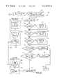
- FIG. 2is a flow chart for a charging method according to the present invention.
- FIG. 3is a flow chart of a ramp-up function for the charging method of FIG. 2;
- FIG. 4is a flow chart of a high current control method for the charging method of FIG. 2;
- FIG. 5is a flow chart of a current regulation method for the charging method of FIG. 2;
- FIG. 6is a flow chart of the method steps for determining charge acceptance ability according to the present invention.
- FIG. 7is a graph showing the relationship between the Ohmic resistance voltage drop and the voltage drop resulting from ion migration through the electrolyte concentration boundary layer
- FIG. 8is a graph showing voltage profiles characteristic of a first class of batteries
- FIG. 9is a graph showing voltage profiles characteristic of a second class of batteries.
- FIG. 10is a graph showing control of the charging current based on the terminal voltage profile.
- FIG. 11is a block diagram of a battery charger suitable for the charging process according to the present invention.
- the charging method according to the present inventionis a closed-loop fast charge method comprising a high current phase and a regulation phase.
- the charging processapplies a high charging current to the battery in order to rapidly charge the battery.
- the charging processreduces the charging current and regulates the charging current to complete the charging cycle for the battery.
- the present inventionprovides a charging method which optimizes the charging cycle to produce a fast charge without damaging the battery.
- FIG. 11shows in block diagram a battery charger 10 for performing the charging method according to the present invention.
- the battery charger 10comprises a controller 12 , a user control interface and display panel 14 , and a programmable power supply 16 .
- the programmable power supply 16generates a charging current I indicated by reference 18 for charging a battery 20 which is coupled to the charger 10 .
- the controller 12is coupled to an analog input on the programmable power supply 16 through a digital-to-analog (D/A) converter 22 .
- the D/A converter 22provides an analog control signal output to the power supply representing the relative level of the charging current I to be applied to the battery 20 .
- the analog inputaccepts a control voltage signal from the D/A converter 22 in the range 0 to 10VDC.
- the control voltage signalrepresents a range of 0% to 100% of the full scale output current capacity of the programmable power supply 16 .
- the programmable supply 16also includes a buffered digital input/output (I/O) interface coupled to respective output and input ports on the controller 12 .
- the programmable power supply 16receives digital control signals issued by the controller 12 for setting the charging current I ON/OFF and for clearing a FAULT condition.
- the power supply 16accepts a digital input signal from the controller 12 which causes the instantaneous shut-down to 0% output charging current I.
- the programmable power supply 16also outputs digital signals to the controller 12 to indicate status and fault conditions, for example, over-temperature, DC bus voltage too high, and DC bus voltage too low.
- One skilled in the artwill be familiar with the implementation of the programmable power supply 16 .
- the controller 12comprises a microprocessor, or processor board, which has been suitably programmed to execute a charging program and control method according to the present invention.
- the charging processis configured by parameters which are entered through the user interface and display panel 14 .
- the user interface and display panel 14preferably comprise a display and a keyboard, or keypad, for entering the charge parameters for a battery type.
- the user interface 14may also include an input device for reading a battery parameter identifier which is associated with certain known types of batteries.
- the controller 12uses the display panel 14 to display battery charge status, charging system status indicators, fault conditions and diagnostic information.
- the display panel 14also includes input keys to start/stop the battery charging process, and display prompts/messages for prompting the user to connect the battery 20 to the charger 1 and enter the charge parameters.
- the charger 10operates as a closed-loop or feedback charging system.
- the charger 10as shown in FIG. 11 includes a sensor module 24 for monitoring various parameters of the battery 20 .
- the sensorsinclude a charging current sensor 26 , a battery voltage sensor 28 , a battery pressure sensor 30 , and a battery temperature sensor 32 .
- the battery temperature sensor 32provides a primarily diagnostic function as the reference voltage setpoint (SV ref ) is determined from the slope of the voltage profile and therefore temperature values for compensating the set-point reference SV ref are not necessary and the temperature sensor 32 merely provides a diagnostic input to the controller 12 .
- the sensors 26 , 28 , 30 , 32comprise analog process measurement circuits and are coupled to respective input ports in the controller 12 through an analog-to-digital (A/D) converter 34 .
- A/Danalog-to-digital
- the charging current sensor 26monitors the charging current I and is implemented using a current transducer, such as the LEM Module LT 500 available from LEM S.A. of Switzerland, connected to a load resistor and an analog amplifier (not shown) for conditioning the signal.
- a current transducersuch as the LEM Module LT 500 available from LEM S.A. of Switzerland
- LEM S.A.available from LEM S.A. of Switzerland
- an analog amplifiernot shown
- the battery voltage sensor 28monitors the output voltage of the battery 20 and preferably comprises a scalable signal conditioning amplifier (not shown) having galvanic isolation, for example, provided by an opto-coupler (not shown).
- the battery pressure sensor 30monitors the internal pressure of the battery 20 and is implemented using a suitable pressure transducer such as the PX302 model available from Omega Engineering Inc.
- the battery temperature sensor 32monitors the internal temperature of the battery 20 and is implemented using a solid state thermal sensor which is placed in contact with the exterior wall of the battery 20 .
- a suitable temperature sensoris the LM335A solid state device available from National Semiconductor of Santa Clara, Calif.
- the temperature sensor 32may include an analog conditioning amplifier (not shown) to condition the output signal from the temperature sensor 32 .
- the output signals from the sensors 26 - 32are fed into the A/D converter 34 and digitized for input by the controller 12 .
- the A/D converter 34comprises a high speed 12-bit converter.
- the digitized signals read by the controller 12 from the A/D converter 34are utilized by the battery charging program and method in conjunction with battery and charge parameters inputted by the user.
- the process control program for the battery charger 10calculates and updates the control commands for the programmable power supply 16 .
- the process control programalso continues to monitor the status and operation of the programmable power supply 16 . If any faults are detected, the battery charging program terminates the charging cycle, i.e. turns off the power supply 16 and indicates the abort or fault status on the user display panel 14 .
- the processing steps embodied in the battery charging program and methodare described in detail below with reference to FIGS. 1 to 10 .
- the maximum rate at which a battery can accept current at any given moment without being overchargedis termed the charge acceptance ability.
- the charge acceptance ability or CAAis a function of the state of charge, temperature, age of battery and previous charging history. It is a feature of the present invention that the charging current I applied to the battery is controlled on the basis of the charge acceptance ability of the battery.
- the charge acceptance abilityis determined from the slope of the terminal voltage profile. According to this aspect of the invention, it has been found that the terminal voltage profile calculated for a battery during a charging cycle will exhibit certain characteristics and these characteristics are used to determine the charge acceptance ability, i.e. the ability of the battery to take the charging current, over the charging cycle.
- FIG. 1shows in block diagram form the organization of a battery charging program 100 according to the present invention.
- the battery charging program 100comprises a charging control module 102 , a user interface module 104 , a charger output module 106 , a charger input module 108 , and a process measurement module 110 .
- the charging control module 102comprises the method steps for controlling the charging of the battery according to the present invention.
- the charging control module 102is described in more detail below with reference to FIGS. 2 to 10 .
- the user interface module 104comprises the functions which control the operation of the user control and display panel 14 (FIG. 11 ).
- the user interface module 104processes inputs entered by the user into charge control parameters 112 which are used by the charge control module 102 as described in more detail below.
- the user interface module 104also displays data from the charging control module 102 on the charging process as process outputs 114 and as diagnostic information 116 on the display panel 14 .
- the charger output module 106controls the operation of the programmable power supply 16 in response to control commands issued by the charging control module 102 .
- the charger output module 106provides the digital control signals to the D/A converter 22 in order to generate the control voltage signal for the programmable power supply 16 .
- the charger output module 106also generates the digital output signals, e.g. charge current ON/OFF and FAULT reset, to control the programmable power supply 16 .
- the charger input module 108receives the status and fault condition signals issued by the programmable power supply 16 .
- the status and fault condition signalsare received on the input port of the controller 12 and transmitted to the charging control module 102 for processing. For example, in response to a high pressure condition, the charging control module 102 aborts charging the battery 20 , the power supply 16 is shut down through the charger output module 106 , and an “abort message” is displayed on the display panel 14 by the user interface module 104 .
- the process measurement module 110oversees the input of signals from the charging current, battery voltage, battery pressure, and battery temperature sensors 26 , 28 , 30 , 32 (FIG. 11 ).
- the analog inputs from the sensorsare then digitized by the A/D converter 34 .
- the digitized information obtained from the sensorsis then stored in memory for use by the charging control module 102 as will be described in more detail below.
- FIG. 2shows the operation of the battery charger 10 and the charging control module 102 according to the present invention.
- the charging control 102reads the battery type identifier in step 103 if the charger 10 includes an input device for reading the battery identifier. If the charger 10 does not include a reader for the battery type, then the user is prompted to input the battery type using the interface 14 .
- the battery type informationi.e. chemistry, is needed to determine the terminal voltage profile. The battery type is also used to select an appropriate Parameter table in step 105 .
- the terminal voltage profile and the Parameter tableare dependent on the type of battery.
- batteriesare categorized, in Group I or Group II.
- Group I batteriescomprise the most common battery types and include lead-acid and nickel-cadmium batteries.
- Group II batterieshave a terminal voltage profile with a slope dV/dt as shown in FIG. 8 .
- the terminal voltage profileis defined as the voltage of the battery when the charging current I is interrupted or varied as will be described below.
- the slope dV/dt for the terminal voltage profileis almost flat as shown by curve 120 a .
- the slope dV/dt of the terminal voltage profileincreases as shown by curves 120 b , 120 c , 120 d .
- the slope dV/dt of the terminal voltage profilereaches its maximum value as shown by curve 122 .
- the maximum slope dV/d t of the terminal voltage profilei.e. curve 122 in FIG. 8, means that charge acceptance ability CAA of the battery has been reached and the charging current I must be reduced in order to avoid overheating and damaging the battery.
- Group II batteriescomprise nickel-metal hydride batteries.
- Group II batterieshave a terminal voltage profile with a slope dV/dt as shown by the curves in FIG. 9 .
- the slope dV/dt of the terminal voltage profilei.e. taken during the current variation interval
- the slope dV/dt of the terminal voltage profiledecreases as shown by curves 124 b , 124 c and 124 d in FIG. 9 .
- the slope dV/dt of the terminal voltage profileapproaches zero as shown by curve 126 in FIG. 9 .
- the Parameter table read in step 105is dependent on the particular type of battery, e.g. nickel-cadmium or lead-acid (Group I) or nickel-metal hydride (Group II).
- the tablepreferably includes charge parameters, safety limits, and a sampling rate or resolution for the input/output timers described in more detail below.
- the parameters for various types of batteries contemplated for the charger 10are stored in non-volatile memory, which is accessible by the controller 12 .
- the data acquisition module 201oversees the input of data from the sensors 26 to 32 (FIG. 11 ).
- the real time process module 202outputs the digital control signals and the current control signal (via the D/A converter 22 ) to the programmable power supply 16 .
- step 203 of the real time process control module 202a time-base for outputting the output control commands is generated.
- step 205the output control commands are sent to the appropriate hardware drivers.
- the loop-back 207provides a “trigger” for the real time data acquisition module 201 as described below.
- the data acquisition module 201generates a time-base for inputting, i.e. sampling, data.
- the sampling ratedepends on the particular hardware being utilized and the desired resolution for the process control as will be appreciated by those skilled in the art. For example, sampling once every 60 microseconds is suitable for the charger.
- the data acquisition module 201collects (at the sampling rate) current readings I 1 , . . . I n from the charging current sensor 26 (FIG. 11 ), voltage readings V 1 , . . . V n from the battery voltage sensor 28 , pressure readings P 1 , . . . P n from the battery pressure sensor 30 , and temperature readings T 1 , . . . T n from the battery temperature sensor 32 .
- step 213values for average voltage V av , average charging current I av , Coulombic charge Q, charge energy E, and elapsed charging time are calculated from the input data.
- the average current I av and average voltage V av valuesare calculated over a selected period. For example, one second.
- the Coulombic charge Qis calculated by integrating the values for the charging current I 1 , . . . and the charge energy E is calculated from the average current I av and the average voltage V av .
- step 211data corresponding to the high value for the charging current I Hi , the low value for the charging current I Low , the high value for the voltage V Hi , the low value for the voltage V Low , are also read in conjunction with the trigger provided on the loop-back path 207 from the real time process control module 202 .
- the trigger for the high charging current I Hicomprises the output command to the programmable power supply 16 to raise the charging current I to the high value.
- the trigger for the low charging current I Lowcomprises the output command to the power supply 16 to lower the charging current I to the low value.
- the values for the high voltage V Hi and the low voltage V Loware read in a similar manner.
- the data generated by the data acquisition module 201is stored in memory for further processing.
- the Ramp Up statusmeans that the charging current I is ramped-up or increased to a HIGH current level. Then during the HIGH current phase of the charging cycle, the charging current I is maintained at a HIGH value until the charge acceptance ability of the battery is reached, at which time the charging current is regulated to complete or finish the charging of the battery.
- step 109the “RAMP UP” status is checked. If the charger 1 is in RAMP UP mode, then a Ramp Up procedure 300 is called in step 111 .
- the function of the Ramp Up procedure 300is to increase or ramp the charging current I to the maximum value I MAX allowed for the particular battery being charged. The maximum current I MAX is conveniently stored in the Parameter table.
- the Ramp Up procedure 300is shown in more detail in FIG. 3 .
- the first operation performed by the Ramp-Up procedure 300is to calculate the charge acceptance ability CAA of the battery being charged.
- a charge acceptance ability procedure 400is called, and the charge acceptance ability procedure 400 is shown in more detail in FIG. 6 .
- the function of the charge acceptance procedure 400is to determine whether the charge acceptance ability of the battery has been reached. If the charge acceptance ability of the battery has not been reached, then the charging current I can be increased to continue the fast charging of the battery.
- the charge acceptance ability CAAis determined from the slope dV/dt of the terminal voltage profile (FIGS. 8 and 9 ).
- the charge acceptance ability procedure 400first checks the mode of operation in step 401 , and more specifically, if the mode is REGULATE. If the mode of operation is not REGULATE, then the charger 10 is in HIGH CURRENT or RAMP UP mode and the battery type is next checked in step 403 .
- the charging method according to the present inventiondistinguishes between Group I and Group II batteries and uses the slope dV/dt of the terminal voltage profile to ascertain the charge acceptance ability CAA of the battery. If the battery is a nickel-metal hydride (NiMH) battery in Group II, then the slope dV/dt for the terminal voltage profile approaches zero (FIG. 9) when the charge acceptance ability is reached, i.e.
- NiMHnickel-metal hydride
- the charge acceptance ability CAAis calculated in step 405 by taking the difference between the maximum value for the slope dV/dt MAX and the present slope dV/dt for the terminal voltage profile.
- the terminal voltage profileis measured during a variation interval in the charging current or calculated from the terminal voltage by means of charging current I and battery internal resistance when the current is not interrupted.
- the charging current Iis interrupted or varied, there is a drop in the terminal voltage (represented by the curve in FIG. 7) comprising two components or phases: voltage V R and voltage V D .
- the voltage V Ris a voltage transpose and occurs almost simultaneously after the charging current I is varied, indicated at time T 1 in FIG. 7 .
- the voltage transpose ⁇ V Ris caused almost entirely by Ohmic losses inside the battery (e.g. Ohmic losses in the posts, plates, intercell wiring and the like).
- the second componentcomprises a voltage charge ⁇ V D in the terminal voltage.
- the voltage charge ⁇ V Dhas a slope dV/dt and according to this aspect of the invention the slope dV/dt of the terminal voltage profile is utilized to determine the charge acceptance ability of the battery.
- the charge acceptance ability CAAis calculated in step 407 .
- the slope dV/dt of the terminal voltage profileapproaches a minimum when the battery is charged.
- the charge acceptance ability CAAis calculated as the difference between the minimum slope dV/dt MIN and the current slope dV/dt of the terminal voltage profile.
- the difference between the minimum slope dV/dt MIN and the slope dV/dtwill approach zero.
- a counter flag “n”is checked in step 409 .
- REGULATE modethe charge acceptance ability CAA is monitored in order to maintain the charging current I at an optimal level.
- the counter flag nis set by the Regulate procedure as will be described below.
- the flag nwill be one and the procedure 400 goes to step 415 .
- a parameter I ⁇ dV/dIis updated.
- the parameter I ⁇ dV/dIrepresents the step changes in the charging current I during the regulation phase and the resulting changes in the voltage dV.
- step 411The relationship between the step decreases in the charging current I and the changes dV in the terminal voltage is shown in FIG. 10 .
- the step size for decreasing the charging current Iis selected so that I/dI is a constant. Accordingly then in step 411 , only the change in voltage dV needs to be measured.
- step 413the charge acceptance ability CAA is calculated as the difference between the first reading (I ⁇ dV/dI) 1 and the present reading (I ⁇ dV/dI) n .
- the first reading (I ⁇ dV/dI) 1corresponds to t he state where CAA is zero, i.e. the battery charge acceptance ability had been reached.
- the procedure 300checks if the charge acceptance ability CAA is greater than zero. If the CAA is greater than zero, then the battery is not fully charged and the charged current I can be increased or ramped-up further. In step 305 , the charging current I is incrementally increased. In step 307 , the setting for charging current I is compared to the maximum allowable current setting I MAX (stored in the Parameter table). If the maximum value for the charging current I is reached, then the status flag is set to HIGH in step 309 to indicate that the charger 10 is operating at high current, and therefore the ramp-up of the charging current I is complete. In step 311 , the Ramp-Up procedure 300 returns to the charger control 100 .
- the Ramp-Up procedure 300checks if the charge acceptance ability CAA is equal to zero in step 313 . If the charge acceptance ability CAA is not equal to zero, i.e. negative, then the charge acceptance ability for the battery has been exceeded and accordingly the charging current I is reduced in step 315 . If the charge acceptance ability CAA is zero (or the maximum charging current has not been reached—step 307 described above), then the Ramp-Up function 300 compares the reading for terminal (e.g. resistance free) voltage V rf (i.e. taken during a variation in the charging current I) to the setpoint voltage SV ref in step 317 .
- terminale.g. resistance free
- the Ramp-Up operationshould be terminated and the status flag is set to “Regulate” in step 319 , and the counter flag “n” is set to zero in step 321 to indicate that the Regulate phase has been commenced. (The counter flag “n” is used by the charge acceptance procedure 400 as described above.) If the terminal voltage V rf is still less than the setpoint voltage SV ref , then the Ramp-Up procedure 300 checks if the time for ramping-up the charging current I has expired in step 323 . For example, if the ramp-up current is not reached within a predetermined time, then there could be a fault and such a condition should be flagged. The Ramp-Up procedure 300 then returns to the calling procedure in step 311 .
- the charging control program 100checks if the status has been set to HIGH in step 113 .
- the statusis set to HIGH by the Ramp-Up procedure 300 when the maximum charging current I MAX is reached as described above. If status is HIGH, then the charging control program 100 calls a High Current Control procedure 500 in step 115 .
- the High Current Control procedure 500controls the charging current I once it has been ramped-up to the maximum value I MAX .
- the first operationinvolves updating the value for the terminal voltage V rf in step 501 .
- the terminal voltage V rfis updated in step 501 based on the current values obtained by the data acquisition module 201 for the voltage V, current I, and resistance R.
- the readings for voltage and currentare taken when the charging current I is interrupted or varied.
- the variation in the charging current Iprovides a window to measure the voltage and current parameters in order to calculate the terminal, i.e. resistance free, voltage V rf for the battery.
- the variations in the charging current Iare regulated by the controller 12 and the programmable power supply 16 (FIG. 11 ). Suitable variations in the current I include a step change (e.g. the current is turned off, decreased to a non-zero value, or increased), a ramped change, a sinusoidal change, an exponential change, a logarithmic change.
- the High Current Control procedure 500checks if the value for the terminal voltage V rf is less than the setpoint voltage SV ref . If the voltage V rf is less than the setpoint voltage SV ref , then the charge acceptance ability CAA of the battery is updated in step 505 . The charge acceptance ability CAA for the battery is calculated as described above with reference to FIG. 6 . If the charge acceptance voltage CAA is greater than zero (step 507 ), then the battery can take more charging current and accordingly the setpoint reference voltage SV ref is increased in step 509 . According to this aspect of the invention, the setpoint voltage SV ref is optimally adjusted using the charge acceptance ability CAA of the battery.
- the setpoint voltage SV ref adjusted in step 509is compared to a maximum setpoint reference voltage (SV ref ) MAX in step 511 . If the maximum setpoint voltage (SV ref ) MAX has been reached, then further charging could damage the battery so the charging status is set to REGULATE in step 513 . Similarly, if the charge acceptance ability CAA is not greater than zero (step 507 ), then the charge status is set to REGULATE in step 513 . Next in step 515 , the counter flag “n” is reset to zero, and High current control procedure returns (step 517 ) to the charging control module 102 .
- SV refmaximum setpoint reference voltage
- the charging control program 102next checks if the status is set for the REGULATE operation in step 117 . (As described above, the High Current Control procedure 500 sets the status to REGULATE.) In step 119 , a Charging Current Regulate procedure 600 is called by the charging control program 102 . The function of the Charging Current Regulate procedure 600 is to regulate the charging current I in order to finish or complete the charging of the battery.
- step 601the Regulate procedure 601 calculates the current value for the terminal, i.e. resistance free, voltage V rf using the voltage, current and resistance readings obtained by the data acquisition module 126 (FIG. 2 ).
- step 603the updated terminal voltage V rf is compared to the setpoint voltage SV ref . If the voltage V rf is greater than the setpoint voltage SV ref , then the Current Regulate procedure 600 ascertains if an equalization operation is to be performed in step 605 .
- An equalization operationinvolves overcharging the battery at the end of a charge cycle with an elevated charging current I.
- the purpose of the elevated charging currentis to bring all the cells in the battery pack to a full charge.
- the equalization operationis typically performed once every fifty charge cycles for a battery pack. If an equalization operation is being conducted, the charging current I is compared to the equalization current value I eq in step 607 . If the charging current I is less than the predetermined equalization current I eq , then the charging current I is set to the equalization value I eq in step 609 and the charge status is set to EQUALIZE in step 611 .
- the Regulate procedure 600then returns to the charging control program 102 in step 613 .
- step 605if equalization has not been selected (step 605 ) or the charging current I exceeds the equalization current (step 607 ), then the counter flag “n” is advanced in step 615 .
- step 617the charging current I is incrementally decreased because the setpoint voltage has been reached.
- step 619the charge acceptance ability CAA is calculated by calling the charge acceptance procedure 400 (as described above with reference to FIG. 6 ).
- the step change in the charging current I in step 617provides a convenient variation in the charging current I for determining the slope dV/dt. If the charge acceptance ability CAA as determined in step 619 is greater than zero (step 621 ), then the battery can take more charge and the setpoint voltage SV ref is checked in step 623 .
- the procedure 600returns control to the charging control program 102 in step 613 .
- the maximum setpoint voltage (SV ref ) MAXhas not been reached, then the setpoint reference voltage SV ref is incrementally increased in step 625 , and control is returned to the charging control program 102 .
- the end of the charging cycleis checked.
- the end of the charging cycleis determined by looking at one or more selected parameters.
- the parametersinclude the elapsed charge time, the value for the Coulombic charge Q, the value for charging current compared to the minimum charging current I MIN , and the rate of change in the battery voltage dV/d ⁇ . For example, if the charging current being applied to the battery has tapered to the minimum value I MIN , then it is assumed that the battery has been charged, i.e. it cannot accept further charge. Similarly, if the rate of change of battery voltage is essentially zero, then it is assumed that the battery is charged.
- a normal end of charge sequenceis initiated in step 123 . If a finishing or equalization charge (FIG. 5) is being applied, then the end of charge corresponds to the termination of the finishing charge sequence.
- the end of charge sequenceincludes an orderly shutdown of the programmable power supply 16 (FIG. 11 ), i.e. the charging current I, and other hardware devices, followed by displaying a notification message on the panel 14 .
- step 125the charging process continues and the safety limits are checked in step 125 .
- the safety check in step 125ensures that the charging cycle is still proceeding within the prescribed safety limits.
- the parameters checked in step 125include the maximum allowable voltage V MAX , the minimum voltage V MIN , the maximum allowable battery temperature T MAX , the maximum allowable Coulombic charge Q MAX , the battery internal resistance R, and the battery pressure P.
- the maximum allowable values for these parametersdepend on the electrochemical characteristics of the battery being charged, and may be conveniently stored in the Parameter table.
- step 125If one of the safety limits is exceeded in step 125 , a fault condition is entered in step 127 , and the charging cycle is terminated in step 129 . The termination of the charging cycle is indicated on the display panel 14 .
- control parameters and dataare updated in step 131 .
- the control parameters and datacontrol the magnitude and application (i.e. variation) of the charging current being applied to the battery.
- the control parametersare then passed to the real time control module 202 in order to control the hardware devices, e.g. the programmable power supply 16 .
Landscapes
- Engineering & Computer Science (AREA)
- Power Engineering (AREA)
- Secondary Cells (AREA)
- Charge And Discharge Circuits For Batteries Or The Like (AREA)
Abstract
Description

Claims (22)
Priority Applications (6)
| Application Number | Priority Date | Filing Date | Title |
|---|---|---|---|
| US08/832,010US6495992B1 (en) | 1996-03-26 | 1997-04-02 | Method and apparatus for charging batteries utilizing heterogeneous reaction kinetics |
| AU69139/98AAU6913998A (en) | 1997-04-02 | 1998-04-02 | Method and apparatus for charging batteries utilizing heterogeneous reaction kinetics |
| CA002285353ACA2285353C (en) | 1997-04-02 | 1998-04-02 | Method and apparatus for charging batteries utilizing heterogeneous reaction kinetics |
| PCT/CA1998/000308WO1998044614A1 (en) | 1997-04-02 | 1998-04-02 | Method and apparatus for charging batteries utilizing heterogeneous reaction kinetics |
| EP98914735AEP0972328B1 (en) | 1997-04-02 | 1998-04-02 | Method and apparatus for charging batteries utilizing heterogeneous reaction kinetics |
| DE69821607TDE69821607T2 (en) | 1997-04-02 | 1998-04-02 | METHOD AND DEVICE FOR CHARGING BATTERIES USING HETEROGENEOUS REACTION KINETICS |
Applications Claiming Priority (2)
| Application Number | Priority Date | Filing Date | Title |
|---|---|---|---|
| US08/621,930US5680031A (en) | 1996-03-26 | 1996-03-26 | Method and apparatus for charging batteries |
| US08/832,010US6495992B1 (en) | 1996-03-26 | 1997-04-02 | Method and apparatus for charging batteries utilizing heterogeneous reaction kinetics |
Related Parent Applications (1)
| Application Number | Title | Priority Date | Filing Date |
|---|---|---|---|
| US08/621,930Continuation-In-PartUS5680031A (en) | 1996-03-26 | 1996-03-26 | Method and apparatus for charging batteries |
Publications (1)
| Publication Number | Publication Date |
|---|---|
| US6495992B1true US6495992B1 (en) | 2002-12-17 |
Family
ID=25260421
Family Applications (1)
| Application Number | Title | Priority Date | Filing Date |
|---|---|---|---|
| US08/832,010Expired - LifetimeUS6495992B1 (en) | 1996-03-26 | 1997-04-02 | Method and apparatus for charging batteries utilizing heterogeneous reaction kinetics |
Country Status (6)
| Country | Link |
|---|---|
| US (1) | US6495992B1 (en) |
| EP (1) | EP0972328B1 (en) |
| AU (1) | AU6913998A (en) |
| CA (1) | CA2285353C (en) |
| DE (1) | DE69821607T2 (en) |
| WO (1) | WO1998044614A1 (en) |
Cited By (37)
| Publication number | Priority date | Publication date | Assignee | Title |
|---|---|---|---|---|
| US20030090239A1 (en)* | 2000-04-13 | 2003-05-15 | Kazuyuki Sakakibara | Adapter for battery charger |
| US20030094927A1 (en)* | 2001-11-20 | 2003-05-22 | Vladimir Pavlovic | Method and apparatus for ameliorating electrolyte stratification during rapid charging |
| US20030102846A1 (en)* | 1999-12-17 | 2003-06-05 | Friedrich Zauner | Battery charger |
| US20040155661A1 (en)* | 2003-02-07 | 2004-08-12 | Field Robert B | Method and system for modeling energy transfer |
| US20040222768A1 (en)* | 2003-05-09 | 2004-11-11 | Moore Stephen W. | System and method for battery charge control based on charge capacity headroom |
| US20040222638A1 (en)* | 2003-05-08 | 2004-11-11 | Vladimir Bednyak | Apparatus and method for providing electrical energy generated from motion to an electrically powered device |
| WO2005043642A3 (en)* | 2003-10-23 | 2005-12-08 | Schumacher Electric Corp | System and methods for charging batteries |
| US20060164043A1 (en)* | 2005-01-26 | 2006-07-27 | Brother Kogyo Kabushiki Kaisha | Electronic Apparatus |
| US20060244424A1 (en)* | 2005-04-28 | 2006-11-02 | Rosemount Inc. | Charging system for field devices |
| US20070105010A1 (en)* | 2005-11-07 | 2007-05-10 | David Cassidy | Lithium polymer battery powered intravenous fluid warmer |
| US20070114970A1 (en)* | 2005-07-15 | 2007-05-24 | Johnson Thomas F | Battery charger and method utilizing alternating DC charging current |
| US20070139008A1 (en)* | 2005-12-15 | 2007-06-21 | Sterz Stephen D | Method and system for charge rate adjustment to enhance battery cycle life |
| US20080238362A1 (en)* | 2007-03-26 | 2008-10-02 | The Gillette Company | Fast Battery Charger Device and Method |
| US20080274772A1 (en)* | 2007-05-02 | 2008-11-06 | Rosemount Inc. | Industrial process field device with improved battery assembly |
| US7795840B2 (en) | 2007-09-12 | 2010-09-14 | Illinois Tool Works, Inc. | Battery charger with a planar bus |
| US7868588B2 (en) | 2007-09-11 | 2011-01-11 | Illinois Tool Works Inc. | Battery charger with wind tunnel cooling |
| EP2089950A4 (en)* | 2006-11-14 | 2011-11-23 | Advanced Analogic Tech Inc | BATTERY CHARGER APPARATUS WITH DIGITAL LOAD REDUCING LOOP |
| US8188708B2 (en) | 2007-09-11 | 2012-05-29 | Illinois Tool Works Inc. | Battery charger with high frequency transformer |
| WO2012128422A1 (en)* | 2011-03-23 | 2012-09-27 | Lo Se Ho | Apparatus and method for charging a lithium battery |
| US20130020994A1 (en)* | 2011-07-20 | 2013-01-24 | Ford Global Technologies, Llc | Method for determining a charge acceptance, and method for charging a rechargeable battery |
| US20130069595A1 (en)* | 2011-09-20 | 2013-03-21 | Marcin Rejman | Hand tool device having at least one charging coil |
| CN103094955A (en)* | 2011-11-07 | 2013-05-08 | 索尼公司 | Charging control system, device and method, and discharging control device |
| US20140084856A1 (en)* | 2012-09-25 | 2014-03-27 | Motorola Mobility Llc | Methods and systems for rapid wireless charging |
| US9419457B2 (en) | 2012-09-04 | 2016-08-16 | Google Technology Holdings LLC | Method and device with enhanced battery capacity savings |
| US9438293B2 (en) | 2014-08-05 | 2016-09-06 | Google Technology Holdings LLC | Tunable circuit elements for dynamic, per element power |
| US9472965B2 (en) | 2014-09-08 | 2016-10-18 | Google Technology Holdings LLC | Battery cycle life through smart overnight charging |
| US9491706B2 (en) | 2013-03-13 | 2016-11-08 | Google Technology Holdings LLC | Reduced-power transmitting from a communications device |
| US9596653B2 (en) | 2013-12-16 | 2017-03-14 | Google Technology Holdings LLC | Remedying power drain via a coverage map |
| US20170294790A1 (en)* | 2015-09-22 | 2017-10-12 | Guangdong Oppo Mobile Telecommunications Corp., Ltd. | Charge control method and device, and electronic device |
| US9812901B2 (en) | 2014-11-19 | 2017-11-07 | Thomas & Betts International Llc | Emergency lighting battery charger |
| US9865897B2 (en) | 2014-06-02 | 2018-01-09 | Google Llc | Stacked electrochemical cell with increased energy density |
| CN110313099A (en)* | 2017-11-13 | 2019-10-08 | 株式会社Lg化学 | Method and apparatus for charging a battery |
| US10732224B2 (en) | 2010-04-22 | 2020-08-04 | Enerdel, Inc. | Monitoring battery state of charge |
| US11677102B2 (en) | 2017-12-07 | 2023-06-13 | Yazami Ip Pte. Ltd. | Adaptive charging protocol for fast charging of batteries and fast charging system implementing this protocol |
| US20230253812A1 (en)* | 2022-02-10 | 2023-08-10 | Calb Co., Ltd. | Battery, electronic device and battery charging method |
| US20230268753A1 (en)* | 2022-02-21 | 2023-08-24 | Lenovo (United States) Inc. | Intelligent battery charging based on history |
| US11848427B2 (en)* | 2017-12-07 | 2023-12-19 | Yazami Ip Pte. Ltd. | Non-linear voltammetry-based method for charging a battery and fast charging system implementing this method |
Families Citing this family (5)
| Publication number | Priority date | Publication date | Assignee | Title |
|---|---|---|---|---|
| JP3936179B2 (en)* | 2001-11-30 | 2007-06-27 | パナソニック・イーブイ・エナジー株式会社 | Battery power supply device and current detection method thereof |
| WO2011060269A2 (en)* | 2009-11-13 | 2011-05-19 | Dresser, Inc. | Recharging electric vehicles |
| US10320216B2 (en)* | 2016-05-05 | 2019-06-11 | Gm Global Technology Operations Llc. | Estimation of charge acceptance capability in a battery assembly |
| WO2023052678A1 (en)* | 2021-09-29 | 2023-04-06 | Kempower Oyj | Charging arrangement and method for controlling charging of electric vehicles and computer program product |
| US20240385251A1 (en)* | 2021-09-30 | 2024-11-21 | Nilar International Ab | A method for generating a status signal indicating a battery condition status of a nimh battery pack, and monitoring unit and a quality control system |
Citations (30)
| Publication number | Priority date | Publication date | Assignee | Title |
|---|---|---|---|---|
| US3517293A (en) | 1967-01-31 | 1970-06-23 | Mcculloch Corp | Rapid charging of batteries |
| US3559025A (en) | 1968-07-15 | 1971-01-26 | Mcculloch Corp | Rapid charging of batteries |
| US3597673A (en) | 1969-06-26 | 1971-08-03 | Mcculloch Corp | Rapid charging of batteries |
| US3609503A (en) | 1969-10-20 | 1971-09-28 | Mcculloch Corp | Termination of rapid charging of batteries |
| US3614583A (en) | 1969-10-20 | 1971-10-19 | Mcculloch Corp | Rapid charging of batteries |
| US3614584A (en) | 1970-03-20 | 1971-10-19 | Mccullock Corp | Termination of battery charging |
| US3614582A (en) | 1970-07-13 | 1971-10-19 | Mcculloch Corp | Rapid charging of batteries |
| US4396880A (en)* | 1981-06-05 | 1983-08-02 | Firing Circuits Inc. | Method and apparatus for charging a battery |
| US4746852A (en) | 1984-10-29 | 1988-05-24 | Christie Electric Corp. | Controller for battery charger |
| US4829225A (en) | 1985-10-23 | 1989-05-09 | Electronic Power Devices, Corp. | Rapid battery charger, discharger and conditioner |
| US5160880A (en)* | 1989-05-10 | 1992-11-03 | Allied-Signal Inc. | Method and apparatus for charging and testing batteries |
| US5179335A (en) | 1987-10-09 | 1993-01-12 | Norvik Inc. | Battery charger |
| US5202617A (en) | 1991-10-15 | 1993-04-13 | Norvik Technologies Inc. | Charging station for electric vehicles |
| US5204611A (en) | 1991-03-13 | 1993-04-20 | Norvik Technologies Inc. | Charging circuits for rechargeable batteries and cells |
| US5206578A (en) | 1991-10-15 | 1993-04-27 | Norvik Technologies Inc. | Monitoring system for batteries during charge and discharge |
| WO1993015544A1 (en) | 1992-01-27 | 1993-08-05 | Batonex, Inc. | Battery charger for charging primary cells |
| WO1993015543A1 (en) | 1992-01-22 | 1993-08-05 | Electronic Power Technology, Inc. | Method and apparatus for charging, thawing, and formatting a battery |
| US5304914A (en)* | 1992-01-27 | 1994-04-19 | Batonex Inc. | Process for charging a battery |
| EP0593196A2 (en) | 1992-10-13 | 1994-04-20 | Gnb Battery Technologies Inc. | Method for optimizing the charging of lead-acid batteries and an interactive charger |
| US5489836A (en)* | 1993-05-05 | 1996-02-06 | Yuen; Tang K. | Battery charging circuit for charging NIMH and NICD batteries |
| US5493196A (en)* | 1992-01-27 | 1996-02-20 | Batonex, Inc. | Battery charger for charging alkaline zinc/manganese dioxide cells |
| US5523667A (en)* | 1992-01-27 | 1996-06-04 | Feldstein; Robert S. | Alkaline battery charger and method of operating same |
| US5523668A (en)* | 1994-04-15 | 1996-06-04 | Feldstein; Robert S. | NiCd/NiMH battery charger |
| US5550453A (en)* | 1994-01-24 | 1996-08-27 | Motorola, Inc. | Battery charging method and apparatus |
| US5583413A (en)* | 1994-09-06 | 1996-12-10 | Cruising Equipment, Inc. | Power conversion equipment monitor/controller method and apparatus |
| US5589757A (en)* | 1994-01-26 | 1996-12-31 | Gnb Battery Technologies, Inc. | Apparatus and method for step-charging batteries to optimize charge acceptance |
| US5656920A (en)* | 1992-10-13 | 1997-08-12 | Gnb Battery Technologies, Inc. | Method and apparatus for charging a lead-acid battery |
| US5680031A (en)* | 1996-03-26 | 1997-10-21 | Norvik Traction Inc. | Method and apparatus for charging batteries |
| US5710506A (en)* | 1995-02-07 | 1998-01-20 | Benchmarq Microelectronics, Inc. | Lead acid charger |
| US6094033A (en)* | 1998-10-02 | 2000-07-25 | Georgia Tech Research Corporation | Battery state of charge detector with rapid charging capability and method |
- 1997
- 1997-04-02USUS08/832,010patent/US6495992B1/ennot_activeExpired - Lifetime
- 1998
- 1998-04-02DEDE69821607Tpatent/DE69821607T2/ennot_activeExpired - Lifetime
- 1998-04-02CACA002285353Apatent/CA2285353C/ennot_activeExpired - Fee Related
- 1998-04-02WOPCT/CA1998/000308patent/WO1998044614A1/enactiveIP Right Grant
- 1998-04-02AUAU69139/98Apatent/AU6913998A/ennot_activeAbandoned
- 1998-04-02EPEP98914735Apatent/EP0972328B1/ennot_activeExpired - Lifetime
Patent Citations (33)
| Publication number | Priority date | Publication date | Assignee | Title |
|---|---|---|---|---|
| US3517293A (en) | 1967-01-31 | 1970-06-23 | Mcculloch Corp | Rapid charging of batteries |
| US3559025A (en) | 1968-07-15 | 1971-01-26 | Mcculloch Corp | Rapid charging of batteries |
| US3597673A (en) | 1969-06-26 | 1971-08-03 | Mcculloch Corp | Rapid charging of batteries |
| US3609503A (en) | 1969-10-20 | 1971-09-28 | Mcculloch Corp | Termination of rapid charging of batteries |
| US3614583A (en) | 1969-10-20 | 1971-10-19 | Mcculloch Corp | Rapid charging of batteries |
| US3614584A (en) | 1970-03-20 | 1971-10-19 | Mccullock Corp | Termination of battery charging |
| US3614582A (en) | 1970-07-13 | 1971-10-19 | Mcculloch Corp | Rapid charging of batteries |
| US4396880A (en)* | 1981-06-05 | 1983-08-02 | Firing Circuits Inc. | Method and apparatus for charging a battery |
| US4746852A (en) | 1984-10-29 | 1988-05-24 | Christie Electric Corp. | Controller for battery charger |
| US4829225A (en) | 1985-10-23 | 1989-05-09 | Electronic Power Devices, Corp. | Rapid battery charger, discharger and conditioner |
| US5179335A (en) | 1987-10-09 | 1993-01-12 | Norvik Inc. | Battery charger |
| US5160880A (en)* | 1989-05-10 | 1992-11-03 | Allied-Signal Inc. | Method and apparatus for charging and testing batteries |
| US5204611A (en) | 1991-03-13 | 1993-04-20 | Norvik Technologies Inc. | Charging circuits for rechargeable batteries and cells |
| US5202617A (en) | 1991-10-15 | 1993-04-13 | Norvik Technologies Inc. | Charging station for electric vehicles |
| US5206578A (en) | 1991-10-15 | 1993-04-27 | Norvik Technologies Inc. | Monitoring system for batteries during charge and discharge |
| WO1993015543A1 (en) | 1992-01-22 | 1993-08-05 | Electronic Power Technology, Inc. | Method and apparatus for charging, thawing, and formatting a battery |
| US5307000A (en)* | 1992-01-22 | 1994-04-26 | Electronic Power Technology, Inc. | Method and apparatus for charging, thawing, and formatting a battery |
| US5523667A (en)* | 1992-01-27 | 1996-06-04 | Feldstein; Robert S. | Alkaline battery charger and method of operating same |
| WO1993015544A1 (en) | 1992-01-27 | 1993-08-05 | Batonex, Inc. | Battery charger for charging primary cells |
| US5291116A (en)* | 1992-01-27 | 1994-03-01 | Batonex, Inc. | Apparatus for charging alkaline zinc-manganese dioxide cells |
| US5304914A (en)* | 1992-01-27 | 1994-04-19 | Batonex Inc. | Process for charging a battery |
| US5493196A (en)* | 1992-01-27 | 1996-02-20 | Batonex, Inc. | Battery charger for charging alkaline zinc/manganese dioxide cells |
| EP0593196A2 (en) | 1992-10-13 | 1994-04-20 | Gnb Battery Technologies Inc. | Method for optimizing the charging of lead-acid batteries and an interactive charger |
| US5469043A (en)* | 1992-10-13 | 1995-11-21 | Gnb Battery Technologies Inc. | Method for optimizing the charging of lead-acid batteries and an interactive charger |
| US5656920A (en)* | 1992-10-13 | 1997-08-12 | Gnb Battery Technologies, Inc. | Method and apparatus for charging a lead-acid battery |
| US5489836A (en)* | 1993-05-05 | 1996-02-06 | Yuen; Tang K. | Battery charging circuit for charging NIMH and NICD batteries |
| US5550453A (en)* | 1994-01-24 | 1996-08-27 | Motorola, Inc. | Battery charging method and apparatus |
| US5589757A (en)* | 1994-01-26 | 1996-12-31 | Gnb Battery Technologies, Inc. | Apparatus and method for step-charging batteries to optimize charge acceptance |
| US5523668A (en)* | 1994-04-15 | 1996-06-04 | Feldstein; Robert S. | NiCd/NiMH battery charger |
| US5583413A (en)* | 1994-09-06 | 1996-12-10 | Cruising Equipment, Inc. | Power conversion equipment monitor/controller method and apparatus |
| US5710506A (en)* | 1995-02-07 | 1998-01-20 | Benchmarq Microelectronics, Inc. | Lead acid charger |
| US5680031A (en)* | 1996-03-26 | 1997-10-21 | Norvik Traction Inc. | Method and apparatus for charging batteries |
| US6094033A (en)* | 1998-10-02 | 2000-07-25 | Georgia Tech Research Corporation | Battery state of charge detector with rapid charging capability and method |
Cited By (68)
| Publication number | Priority date | Publication date | Assignee | Title |
|---|---|---|---|---|
| US20030102846A1 (en)* | 1999-12-17 | 2003-06-05 | Friedrich Zauner | Battery charger |
| US20030090239A1 (en)* | 2000-04-13 | 2003-05-15 | Kazuyuki Sakakibara | Adapter for battery charger |
| US20030094927A1 (en)* | 2001-11-20 | 2003-05-22 | Vladimir Pavlovic | Method and apparatus for ameliorating electrolyte stratification during rapid charging |
| US6965216B2 (en)* | 2001-11-20 | 2005-11-15 | Edison Source | Method and apparatus for ameliorating electrolyte stratification during rapid charging |
| US20040155661A1 (en)* | 2003-02-07 | 2004-08-12 | Field Robert B | Method and system for modeling energy transfer |
| US7358701B2 (en) | 2003-02-07 | 2008-04-15 | Field Robert B | Method and system for modeling energy transfer |
| US20040222638A1 (en)* | 2003-05-08 | 2004-11-11 | Vladimir Bednyak | Apparatus and method for providing electrical energy generated from motion to an electrically powered device |
| US7245107B2 (en)* | 2003-05-09 | 2007-07-17 | Enerdel, Inc. | System and method for battery charge control based on a cycle life parameter |
| US20040222768A1 (en)* | 2003-05-09 | 2004-11-11 | Moore Stephen W. | System and method for battery charge control based on charge capacity headroom |
| CN1950998B (en)* | 2003-10-23 | 2015-03-25 | 舒马克电器公司 | System and method for charging a battery |
| US7808211B2 (en) | 2003-10-23 | 2010-10-05 | Schumacher Electric Corporation | System and method for charging batteries |
| WO2005043642A3 (en)* | 2003-10-23 | 2005-12-08 | Schumacher Electric Corp | System and methods for charging batteries |
| US7528579B2 (en) | 2003-10-23 | 2009-05-05 | Schumacher Electric Corporation | System and method for charging batteries |
| US20060164043A1 (en)* | 2005-01-26 | 2006-07-27 | Brother Kogyo Kabushiki Kaisha | Electronic Apparatus |
| US7741812B2 (en)* | 2005-01-26 | 2010-06-22 | Brother Kogyo Kabushiki Kaisha | Battery charging apparatus including notification control unit |
| US20060244424A1 (en)* | 2005-04-28 | 2006-11-02 | Rosemount Inc. | Charging system for field devices |
| US7560907B2 (en)* | 2005-04-28 | 2009-07-14 | Rosemount Inc. | Charging system for field devices |
| US20070114970A1 (en)* | 2005-07-15 | 2007-05-24 | Johnson Thomas F | Battery charger and method utilizing alternating DC charging current |
| US8947054B2 (en) | 2005-07-15 | 2015-02-03 | Schumacher Electric Corporation | Battery charger and method utilizing alternating DC charging current |
| US9893548B2 (en) | 2005-07-15 | 2018-02-13 | Schumacher Electric Corporation | Battery charger and method utilizing alternating DC charging current |
| US8237412B2 (en) | 2005-07-15 | 2012-08-07 | Schumacher Electric Corporation | Battery charger and method utilizing alternating DC charging current |
| US9450435B2 (en) | 2005-07-15 | 2016-09-20 | Schumacher Electric Corporation | Battery charger and method utilizing alternating DC charging current |
| US7741815B2 (en)* | 2005-11-07 | 2010-06-22 | General Electric Company | Lithium polymer battery powered intravenous fluid warmer |
| US8796997B2 (en) | 2005-11-07 | 2014-08-05 | Vital Signs, Inc. | Lithium polymer battery powered intravenous fluid warmer |
| US20100253288A1 (en)* | 2005-11-07 | 2010-10-07 | David Cassidy | Lithium polymer battery powered intravenous fluid warmer |
| US20070105010A1 (en)* | 2005-11-07 | 2007-05-10 | David Cassidy | Lithium polymer battery powered intravenous fluid warmer |
| US7956583B2 (en) | 2005-11-07 | 2011-06-07 | General Electric Company | Lithium polymer battery powered intravenous fluid warmer |
| US20110238012A1 (en)* | 2005-11-07 | 2011-09-29 | David Cassidy | Lithium polymer battery powered intravenous fluid warmer |
| US7518340B2 (en)* | 2005-12-15 | 2009-04-14 | Dell Products L.P. | Method and system for charge rate adjustment to enhance battery cycle life |
| US20070139008A1 (en)* | 2005-12-15 | 2007-06-21 | Sterz Stephen D | Method and system for charge rate adjustment to enhance battery cycle life |
| EP2089950A4 (en)* | 2006-11-14 | 2011-11-23 | Advanced Analogic Tech Inc | BATTERY CHARGER APPARATUS WITH DIGITAL LOAD REDUCING LOOP |
| US20080238362A1 (en)* | 2007-03-26 | 2008-10-02 | The Gillette Company | Fast Battery Charger Device and Method |
| US20080274772A1 (en)* | 2007-05-02 | 2008-11-06 | Rosemount Inc. | Industrial process field device with improved battery assembly |
| US8031453B2 (en) | 2007-05-02 | 2011-10-04 | Rosemount Inc. | Industrial process field device with improved battery assembly |
| US8188708B2 (en) | 2007-09-11 | 2012-05-29 | Illinois Tool Works Inc. | Battery charger with high frequency transformer |
| US7868588B2 (en) | 2007-09-11 | 2011-01-11 | Illinois Tool Works Inc. | Battery charger with wind tunnel cooling |
| US7795840B2 (en) | 2007-09-12 | 2010-09-14 | Illinois Tool Works, Inc. | Battery charger with a planar bus |
| US10732224B2 (en) | 2010-04-22 | 2020-08-04 | Enerdel, Inc. | Monitoring battery state of charge |
| WO2012128422A1 (en)* | 2011-03-23 | 2012-09-27 | Lo Se Ho | Apparatus and method for charging a lithium battery |
| US20130020994A1 (en)* | 2011-07-20 | 2013-01-24 | Ford Global Technologies, Llc | Method for determining a charge acceptance, and method for charging a rechargeable battery |
| US9499066B2 (en)* | 2011-07-20 | 2016-11-22 | Ford Global Technologies, Llc | Method for determining a charge acceptance, and method for charging a rechargeable battery |
| US20130069595A1 (en)* | 2011-09-20 | 2013-03-21 | Marcin Rejman | Hand tool device having at least one charging coil |
| US10170238B2 (en)* | 2011-09-20 | 2019-01-01 | Robert Bosch Gmbh | Hand tool device having at least one charging coil |
| US20130300346A1 (en)* | 2011-11-07 | 2013-11-14 | Sony Corporation | Charge controlling system, charge controlling apparatus, charge controlling method and discharge controlling apparatus |
| CN103094955B (en)* | 2011-11-07 | 2016-08-17 | 索尼公司 | Charge control system, device and method, and discharge control device |
| CN103094955A (en)* | 2011-11-07 | 2013-05-08 | 索尼公司 | Charging control system, device and method, and discharging control device |
| US9059593B2 (en)* | 2011-11-07 | 2015-06-16 | Sony Corporation | Charge controlling system, charge controlling apparatus, charge controlling method and discharge controlling apparatus |
| US9419457B2 (en) | 2012-09-04 | 2016-08-16 | Google Technology Holdings LLC | Method and device with enhanced battery capacity savings |
| US9356461B2 (en)* | 2012-09-25 | 2016-05-31 | Google Technology Holdings, LLC | Methods and systems for rapid wireless charging where the low state of charge (SOC) temperature dependent charging current and low SOC temperature limit are higher than the high SOC temperature dependent charging current and high SOC temperature limit |
| US20140084856A1 (en)* | 2012-09-25 | 2014-03-27 | Motorola Mobility Llc | Methods and systems for rapid wireless charging |
| US9491706B2 (en) | 2013-03-13 | 2016-11-08 | Google Technology Holdings LLC | Reduced-power transmitting from a communications device |
| US9596653B2 (en) | 2013-12-16 | 2017-03-14 | Google Technology Holdings LLC | Remedying power drain via a coverage map |
| US9949210B2 (en) | 2013-12-16 | 2018-04-17 | Google Technology Holdings LLC | Remedying power drain via a coverage map |
| US9865897B2 (en) | 2014-06-02 | 2018-01-09 | Google Llc | Stacked electrochemical cell with increased energy density |
| US9438293B2 (en) | 2014-08-05 | 2016-09-06 | Google Technology Holdings LLC | Tunable circuit elements for dynamic, per element power |
| US9847661B2 (en) | 2014-09-08 | 2017-12-19 | Google Llc | Extended battery cycle life through smart charging of rechargeable batteries |
| US9472965B2 (en) | 2014-09-08 | 2016-10-18 | Google Technology Holdings LLC | Battery cycle life through smart overnight charging |
| US9812901B2 (en) | 2014-11-19 | 2017-11-07 | Thomas & Betts International Llc | Emergency lighting battery charger |
| US10230264B2 (en) | 2014-11-19 | 2019-03-12 | Thomas & Betts International Llc | Emergency lighting battery charger |
| US20200412139A1 (en)* | 2015-09-22 | 2020-12-31 | Guangdong Oppo Mobile Telecommunications Corp., Ltd. | Charge Control Method and Device, and Electronic Device |
| US20170294790A1 (en)* | 2015-09-22 | 2017-10-12 | Guangdong Oppo Mobile Telecommunications Corp., Ltd. | Charge control method and device, and electronic device |
| US10833518B2 (en)* | 2015-09-22 | 2020-11-10 | Guangdong Oppo Mobile Telecommunications Corp., Ltd. | Charge control method and device, and electronic device |
| CN110313099A (en)* | 2017-11-13 | 2019-10-08 | 株式会社Lg化学 | Method and apparatus for charging a battery |
| CN110313099B (en)* | 2017-11-13 | 2022-07-05 | 株式会社Lg化学 | Method and apparatus for charging a battery |
| US11677102B2 (en) | 2017-12-07 | 2023-06-13 | Yazami Ip Pte. Ltd. | Adaptive charging protocol for fast charging of batteries and fast charging system implementing this protocol |
| US11848427B2 (en)* | 2017-12-07 | 2023-12-19 | Yazami Ip Pte. Ltd. | Non-linear voltammetry-based method for charging a battery and fast charging system implementing this method |
| US20230253812A1 (en)* | 2022-02-10 | 2023-08-10 | Calb Co., Ltd. | Battery, electronic device and battery charging method |
| US20230268753A1 (en)* | 2022-02-21 | 2023-08-24 | Lenovo (United States) Inc. | Intelligent battery charging based on history |
Also Published As
| Publication number | Publication date |
|---|---|
| AU6913998A (en) | 1998-10-22 |
| EP0972328A1 (en) | 2000-01-19 |
| WO1998044614A1 (en) | 1998-10-08 |
| DE69821607D1 (en) | 2004-03-18 |
| EP0972328B1 (en) | 2004-02-11 |
| CA2285353C (en) | 2003-09-16 |
| CA2285353A1 (en) | 1998-10-08 |
| DE69821607T2 (en) | 2004-12-23 |
Similar Documents
| Publication | Publication Date | Title |
|---|---|---|
| US6495992B1 (en) | Method and apparatus for charging batteries utilizing heterogeneous reaction kinetics | |
| EP0890213B1 (en) | Method and apparatus for charging batteries | |
| US6965216B2 (en) | Method and apparatus for ameliorating electrolyte stratification during rapid charging | |
| JP3043808B2 (en) | Method for charging rechargeable batteries particularly quickly | |
| US5864220A (en) | Method and apparatus for controlling the charging of a rechargeable battery to ensure that full charge is achieved without damaging the battery | |
| US5694023A (en) | Control and termination of a battery charging process | |
| JP3198439B2 (en) | Method and apparatus for charging a rechargeable battery | |
| US5686815A (en) | Method and apparatus for controlling the charging of a rechargeable battery to ensure that full charge is achieved without damaging the battery | |
| US5583416A (en) | Apparatus and method for step-charging batteries to optimize charge acceptance | |
| US5489836A (en) | Battery charging circuit for charging NIMH and NICD batteries | |
| US20010000212A1 (en) | Battery system providing indicia of a charging parameter | |
| AU710799B2 (en) | Control and termination of a battery charging process | |
| JP3306188B2 (en) | Rechargeable battery charging method | |
| JPH09308126A (en) | Charger | |
| JP3092394B2 (en) | Secondary battery charging method and device | |
| JPH08149709A (en) | Rechargeable battery charger | |
| KR100620871B1 (en) | How to charge the charger for small rechargeable batteries | |
| JP3298276B2 (en) | Battery charging apparatus and charging method | |
| JPH0530667A (en) | Storage battery charger | |
| JP3484867B2 (en) | Battery charger | |
| NZ204697A (en) | Battery charger with automatic recharge control | |
| JPH0382342A (en) | Battery charger |
Legal Events
| Date | Code | Title | Description |
|---|---|---|---|
| AS | Assignment | Owner name:NORVIK TRACTION INC., CANADA Free format text:ASSIGNMENT OF ASSIGNORS INTEREST;ASSIGNOR:PAVLOVIC, VLADIMIR S.;REEL/FRAME:008523/0205 Effective date:19970326 | |
| STCF | Information on status: patent grant | Free format text:PATENTED CASE | |
| AS | Assignment | Owner name:EDISON SOURCE, CALIFORNIA Free format text:ASSIGNMENT OF ASSIGNORS INTEREST;ASSIGNOR:RICHTER & PARTNERS INC.;REEL/FRAME:014446/0493 Effective date:20000606 Owner name:RICHTER & PARTNERS INC., AS RECEIVER, CANADA Free format text:ORDER APPOINTING A RECEIVER;ASSIGNOR:NORVIK TRACTION, INC.;REEL/FRAME:014446/0459 Effective date:20000606 | |
| FEPP | Fee payment procedure | Free format text:PAT HOLDER NO LONGER CLAIMS SMALL ENTITY STATUS, ENTITY STATUS SET TO UNDISCOUNTED (ORIGINAL EVENT CODE: STOL); ENTITY STATUS OF PATENT OWNER: SMALL ENTITY Free format text:PAYER NUMBER DE-ASSIGNED (ORIGINAL EVENT CODE: RMPN); ENTITY STATUS OF PATENT OWNER: SMALL ENTITY Free format text:PAYOR NUMBER ASSIGNED (ORIGINAL EVENT CODE: ASPN); ENTITY STATUS OF PATENT OWNER: SMALL ENTITY | |
| FPAY | Fee payment | Year of fee payment:4 | |
| AS | Assignment | Owner name:G.H.V. REFRIGERATION, INC., CALIFORNIA Free format text:ASSIGNMENT OF ASSIGNORS INTEREST;ASSIGNOR:EDISON SOURCE;REEL/FRAME:020261/0324 Effective date:20071130 | |
| AS | Assignment | Owner name:BRIDGEPOINT MASTER FUND LTD, GEORGIA Free format text:SECURITY AGREEMENT;ASSIGNORS:ECOTALITY, INC.;ELECTRIC TRANSPORTATION ENGINEERING CORPORATION;G.H.V. REFRIGERATION, INC.;REEL/FRAME:022375/0922 Effective date:20071106 Owner name:ENABLE GROWTH PARTNERS LP, CALIFORNIA Free format text:SECURITY AGREEMENT;ASSIGNORS:ECOTALITY, INC.;ELECTRIC TRANSPORTATION ENGINEERING CORPORATION;G.H.V. REFRIGERATION, INC.;REEL/FRAME:022375/0922 Effective date:20071106 Owner name:ENABLE OPPORTUNITY PARTNERS LP, CALIFORNIA Free format text:SECURITY AGREEMENT;ASSIGNORS:ECOTALITY, INC.;ELECTRIC TRANSPORTATION ENGINEERING CORPORATION;G.H.V. REFRIGERATION, INC.;REEL/FRAME:022375/0922 Effective date:20071106 Owner name:PIERCE DIVERSIFIED STRATEGY MASTER FUND LLC, ENA, Free format text:SECURITY AGREEMENT;ASSIGNORS:ECOTALITY, INC.;ELECTRIC TRANSPORTATION ENGINEERING CORPORATION;G.H.V. REFRIGERATION, INC.;REEL/FRAME:022375/0922 Effective date:20071106 | |
| FPAY | Fee payment | Year of fee payment:8 | |
| AS | Assignment | Owner name:ECOTALITY, INC., ARIZONA Free format text:RELEASE BY SECURED PARTY;ASSIGNORS:BRIDGEPOINTE MASTER FUND LTD.;ENABLE GROWTH PARTNERS LP;ENABLE OPPORTUNITY PARTNERS LP;AND OTHERS;SIGNING DATES FROM 20100714 TO 20100722;REEL/FRAME:024860/0784 Owner name:G.H.V. REFRIGERATION, INC., ARIZONA Free format text:RELEASE BY SECURED PARTY;ASSIGNORS:BRIDGEPOINTE MASTER FUND LTD.;ENABLE GROWTH PARTNERS LP;ENABLE OPPORTUNITY PARTNERS LP;AND OTHERS;SIGNING DATES FROM 20100714 TO 20100722;REEL/FRAME:024860/0784 Owner name:ELECTRIC TRANSPORTATION ENGINEERING CORPORATION, A Free format text:RELEASE BY SECURED PARTY;ASSIGNORS:BRIDGEPOINTE MASTER FUND LTD.;ENABLE GROWTH PARTNERS LP;ENABLE OPPORTUNITY PARTNERS LP;AND OTHERS;SIGNING DATES FROM 20100714 TO 20100722;REEL/FRAME:024860/0784 | |
| AS | Assignment | Owner name:ECOTALITY, INC., ARIZONA Free format text:ASSIGNMENT OF ASSIGNORS INTEREST;ASSIGNOR:G.H.V. REFRIGERATION, INC.;REEL/FRAME:025513/0409 Effective date:20101117 | |
| FEPP | Fee payment procedure | Free format text:PAT HOLDER CLAIMS SMALL ENTITY STATUS, ENTITY STATUS SET TO SMALL (ORIGINAL EVENT CODE: LTOS); ENTITY STATUS OF PATENT OWNER: SMALL ENTITY | |
| AS | Assignment | Owner name:ACCESS CONTROL GROUP, L.L.C.,, NEW JERSEY Free format text:ASSIGNMENT OF ASSIGNORS INTEREST;ASSIGNOR:ECOTALITY, INC.,;REEL/FRAME:032636/0522 Effective date:20140122 | |
| AS | Assignment | Owner name:MINIT CHARGER, LLC, NEW JERSEY Free format text:ASSIGNMENT OF ASSIGNORS INTEREST;ASSIGNOR:ACCESS CONTROL GROUP, LLC;REEL/FRAME:032803/0547 Effective date:20140501 | |
| FPAY | Fee payment | Year of fee payment:12 |