US6494907B1 - Braided stent - Google Patents
Braided stentDownload PDFInfo
- Publication number
- US6494907B1 US6494907B1US09/067,665US6766598AUS6494907B1US 6494907 B1US6494907 B1US 6494907B1US 6766598 AUS6766598 AUS 6766598AUS 6494907 B1US6494907 B1US 6494907B1
- Authority
- US
- United States
- Prior art keywords
- strand
- over
- under
- strands
- catheter
- Prior art date
- Legal status (The legal status is an assumption and is not a legal conclusion. Google has not performed a legal analysis and makes no representation as to the accuracy of the status listed.)
- Expired - Lifetime
Links
- 229910052751metalInorganic materials0.000claimsabstractdescription11
- 239000002184metalSubstances0.000claimsabstractdescription11
- 230000006835compressionEffects0.000claimsabstractdescription6
- 238000007906compressionMethods0.000claimsabstractdescription6
- 230000004044responseEffects0.000claimsabstractdescription5
- 238000000034methodMethods0.000claimsdescription24
- 238000009954braidingMethods0.000claimsdescription6
- 238000002513implantationMethods0.000abstractdescription5
- 239000000463materialSubstances0.000description18
- 208000027418Wounds and injuryDiseases0.000description8
- 238000004519manufacturing processMethods0.000description5
- 229910001000nickel titaniumInorganic materials0.000description5
- 230000002792vascularEffects0.000description5
- 238000003466weldingMethods0.000description5
- 208000031481Pathologic ConstrictionDiseases0.000description4
- 238000002399angioplastyMethods0.000description4
- 239000007787solidSubstances0.000description4
- 230000036262stenosisEffects0.000description4
- 208000037804stenosisDiseases0.000description4
- 238000002224dissectionMethods0.000description3
- 239000007943implantSubstances0.000description3
- HLXZNVUGXRDIFK-UHFFFAOYSA-Nnickel titaniumChemical compound[Ti].[Ti].[Ti].[Ti].[Ti].[Ti].[Ti].[Ti].[Ti].[Ti].[Ti].[Ni].[Ni].[Ni].[Ni].[Ni].[Ni].[Ni].[Ni].[Ni].[Ni].[Ni].[Ni].[Ni].[Ni]HLXZNVUGXRDIFK-UHFFFAOYSA-N0.000description3
- HVYWMOMLDIMFJA-DPAQBDIFSA-NcholesterolChemical compoundC1C=C2C[C@@H](O)CC[C@]2(C)[C@@H]2[C@@H]1[C@@H]1CC[C@H]([C@H](C)CCCC(C)C)[C@@]1(C)CC2HVYWMOMLDIMFJA-DPAQBDIFSA-N0.000description2
- 210000004351coronary vesselAnatomy0.000description2
- 206010002329AneurysmDiseases0.000description1
- 208000037260Atherosclerotic PlaqueDiseases0.000description1
- 241001465754MetazoaSpecies0.000description1
- HZEWFHLRYVTOIW-UHFFFAOYSA-N[Ti].[Ni]Chemical compound[Ti].[Ni]HZEWFHLRYVTOIW-UHFFFAOYSA-N0.000description1
- 230000001154acute effectEffects0.000description1
- 229910045601alloyInorganic materials0.000description1
- 239000000956alloySubstances0.000description1
- 210000003484anatomyAnatomy0.000description1
- 230000004323axial lengthEffects0.000description1
- 239000000560biocompatible materialSubstances0.000description1
- 239000008280bloodSubstances0.000description1
- 210000004369bloodAnatomy0.000description1
- 238000005219brazingMethods0.000description1
- 210000000621bronchiAnatomy0.000description1
- 235000012000cholesterolNutrition0.000description1
- 230000001684chronic effectEffects0.000description1
- 238000007887coronary angioplastyMethods0.000description1
- 230000007797corrosionEffects0.000description1
- 238000005260corrosionMethods0.000description1
- 238000002788crimpingMethods0.000description1
- 230000001186cumulative effectEffects0.000description1
- 230000003247decreasing effectEffects0.000description1
- 229910000701elgiloys (Co-Cr-Ni Alloy)Inorganic materials0.000description1
- 239000004744fabricSubstances0.000description1
- 239000003925fatSubstances0.000description1
- 230000006870functionEffects0.000description1
- 210000000232gallbladderAnatomy0.000description1
- 238000001727in vivoMethods0.000description1
- 208000014674injuryDiseases0.000description1
- 210000004185liverAnatomy0.000description1
- 239000011159matrix materialSubstances0.000description1
- 210000003137popliteal arteryAnatomy0.000description1
- 235000020004porterNutrition0.000description1
- 210000002307prostateAnatomy0.000description1
- 208000037803restenosisDiseases0.000description1
- 238000005476solderingMethods0.000description1
- 239000010935stainless steelSubstances0.000description1
- 229910001220stainless steelInorganic materials0.000description1
- 238000001356surgical procedureMethods0.000description1
- 229910052715tantalumInorganic materials0.000description1
- GUVRBAGPIYLISA-UHFFFAOYSA-Ntantalum atomChemical compound[Ta]GUVRBAGPIYLISA-UHFFFAOYSA-N0.000description1
- 238000002560therapeutic procedureMethods0.000description1
- 210000001519tissueAnatomy0.000description1
- 210000003437tracheaAnatomy0.000description1
- 230000008733traumaEffects0.000description1
- 230000000472traumatic effectEffects0.000description1
- 210000001177vas deferenAnatomy0.000description1
- 238000004804windingMethods0.000description1
Images


Classifications
- A—HUMAN NECESSITIES
- A61—MEDICAL OR VETERINARY SCIENCE; HYGIENE
- A61F—FILTERS IMPLANTABLE INTO BLOOD VESSELS; PROSTHESES; DEVICES PROVIDING PATENCY TO, OR PREVENTING COLLAPSING OF, TUBULAR STRUCTURES OF THE BODY, e.g. STENTS; ORTHOPAEDIC, NURSING OR CONTRACEPTIVE DEVICES; FOMENTATION; TREATMENT OR PROTECTION OF EYES OR EARS; BANDAGES, DRESSINGS OR ABSORBENT PADS; FIRST-AID KITS
- A61F2/00—Filters implantable into blood vessels; Prostheses, i.e. artificial substitutes or replacements for parts of the body; Appliances for connecting them with the body; Devices providing patency to, or preventing collapsing of, tubular structures of the body, e.g. stents
- A61F2/82—Devices providing patency to, or preventing collapsing of, tubular structures of the body, e.g. stents
- A61F2/86—Stents in a form characterised by the wire-like elements; Stents in the form characterised by a net-like or mesh-like structure
- A61F2/90—Stents in a form characterised by the wire-like elements; Stents in the form characterised by a net-like or mesh-like structure characterised by a net-like or mesh-like structure
- A—HUMAN NECESSITIES
- A61—MEDICAL OR VETERINARY SCIENCE; HYGIENE
- A61F—FILTERS IMPLANTABLE INTO BLOOD VESSELS; PROSTHESES; DEVICES PROVIDING PATENCY TO, OR PREVENTING COLLAPSING OF, TUBULAR STRUCTURES OF THE BODY, e.g. STENTS; ORTHOPAEDIC, NURSING OR CONTRACEPTIVE DEVICES; FOMENTATION; TREATMENT OR PROTECTION OF EYES OR EARS; BANDAGES, DRESSINGS OR ABSORBENT PADS; FIRST-AID KITS
- A61F2/00—Filters implantable into blood vessels; Prostheses, i.e. artificial substitutes or replacements for parts of the body; Appliances for connecting them with the body; Devices providing patency to, or preventing collapsing of, tubular structures of the body, e.g. stents
- A61F2/02—Prostheses implantable into the body
- A61F2/04—Hollow or tubular parts of organs, e.g. bladders, tracheae, bronchi or bile ducts
- A61F2/06—Blood vessels
- A61F2/064—Blood vessels with special features to facilitate anastomotic coupling
- A—HUMAN NECESSITIES
- A61—MEDICAL OR VETERINARY SCIENCE; HYGIENE
- A61F—FILTERS IMPLANTABLE INTO BLOOD VESSELS; PROSTHESES; DEVICES PROVIDING PATENCY TO, OR PREVENTING COLLAPSING OF, TUBULAR STRUCTURES OF THE BODY, e.g. STENTS; ORTHOPAEDIC, NURSING OR CONTRACEPTIVE DEVICES; FOMENTATION; TREATMENT OR PROTECTION OF EYES OR EARS; BANDAGES, DRESSINGS OR ABSORBENT PADS; FIRST-AID KITS
- A61F2220/00—Fixations or connections for prostheses classified in groups A61F2/00 - A61F2/26 or A61F2/82 or A61F9/00 or A61F11/00 or subgroups thereof
- A61F2220/0025—Connections or couplings between prosthetic parts, e.g. between modular parts; Connecting elements
- A61F2220/0058—Connections or couplings between prosthetic parts, e.g. between modular parts; Connecting elements soldered or brazed or welded
- A—HUMAN NECESSITIES
- A61—MEDICAL OR VETERINARY SCIENCE; HYGIENE
- A61F—FILTERS IMPLANTABLE INTO BLOOD VESSELS; PROSTHESES; DEVICES PROVIDING PATENCY TO, OR PREVENTING COLLAPSING OF, TUBULAR STRUCTURES OF THE BODY, e.g. STENTS; ORTHOPAEDIC, NURSING OR CONTRACEPTIVE DEVICES; FOMENTATION; TREATMENT OR PROTECTION OF EYES OR EARS; BANDAGES, DRESSINGS OR ABSORBENT PADS; FIRST-AID KITS
- A61F2230/00—Geometry of prostheses classified in groups A61F2/00 - A61F2/26 or A61F2/82 or A61F9/00 or A61F11/00 or subgroups thereof
- A61F2230/0063—Three-dimensional shapes
- A61F2230/0091—Three-dimensional shapes helically-coiled or spirally-coiled, i.e. having a 2-D spiral cross-section
- A—HUMAN NECESSITIES
- A61—MEDICAL OR VETERINARY SCIENCE; HYGIENE
- A61F—FILTERS IMPLANTABLE INTO BLOOD VESSELS; PROSTHESES; DEVICES PROVIDING PATENCY TO, OR PREVENTING COLLAPSING OF, TUBULAR STRUCTURES OF THE BODY, e.g. STENTS; ORTHOPAEDIC, NURSING OR CONTRACEPTIVE DEVICES; FOMENTATION; TREATMENT OR PROTECTION OF EYES OR EARS; BANDAGES, DRESSINGS OR ABSORBENT PADS; FIRST-AID KITS
- A61F2240/00—Manufacturing or designing of prostheses classified in groups A61F2/00 - A61F2/26 or A61F2/82 or A61F9/00 or A61F11/00 or subgroups thereof
- A61F2240/001—Designing or manufacturing processes
Definitions
- the present inventionrelates to intravascular stent implants for maintaining vascular patency in humans and animals and more particularly to a stent in the form of a braided stent.
- Percutaneous transluminal coronary angioplastyis used to increase the lumen diameter of a coronary artery partially or totally obstructed by a build-up of cholesterol fats or atherosclerotic plaque.
- a first guidewire of about 0.038 inches in diameteris steered through the vascular system to the site of therapy.
- a guiding catheterfor example, can then be advanced over the first guidewire to a point just proximal of the stenosis. The first guidewire is then removed.
- a balloon catheter on a smaller 0.014 inch diameter second guidewireis advanced within the guiding catheter to a point just proximal of the stenosis.
- the second guidewireis advanced into the stenosis, followed by the balloon on the distal end of the catheter.
- the balloonis inflated causing the site of the stenosis to widen.
- the dilatation of the occlusioncan form flaps, fissures and dissections which threaten reclosure of the dilated vessel or even perforations in the vessel wall.
- Implantation of a metal stentcan provide support for such flaps and dissections and thereby prevent reclosure of the vessel or provide a patch repair for a perforated vessel wall until corrective surgery can be performed. It has also been shown that the use of intravascular stents can measurably decrease the incidence of restenosis after angioplasty thereby reducing the likelihood that a secondary angioplasty procedure or a surgical bypass operation will be necessary.
- An implanted prosthesissuch as a stent can preclude additional procedures and maintain vascular patency by mechanically supporting dilated vessels to prevent vessel reclosure.
- Stentscan also be used to repair aneurysms, to support artificial vessels as liners of vessels or to repair dissections.
- Stentsare suited to the treatment of any body lumen, including the vas deferens, ducts of the gallbladder, prostate gland, trachea, bronchus and liver.
- the body lumensrange in diameter from small coronary vessels of 3 mm or less to 28 mm in the aortic vessel.
- the inventionapplies to acute and chronic closure or reclosure of body lumens.
- a typical stentis a cylindrically shaped wire formed device intended to act as a permanent prosthesis.
- a typical stentranges from 5 mm to 50 mm in length.
- a stentis deployed in a body lumen from a radially compressed configuration into a radially expanded configuration which allows it to contact and support a body lumen.
- the stentcan be made to be radially self-expanding or expandable by the use of an expansion device.
- the self expanding stentis made from a resilient springy material while the device expandable stent is made from a material which is plastically deformable.
- a plastically deformable stentcan be implanted during a single angioplasty procedure by using a catheter bearing a stent which has been secured to the catheter such as in U.S. Pat. No. 5,372,600 to Beyar et al. which is incorporated herein by reference in its entirety.
- the stentmust be reduced in size to facilitate its delivery to the intended implantation site.
- a coil stentis delivered by winding it into a smaller diameter and fixing it onto a delivery catheter.
- the coilis released from the catheter and it either self-expands by its spring force or it is otherwise mechanically expanded to the specified dimension.
- the firstis the degree of deformation applied to the stent and the second is the thickness of the stent material.
- the strain experienced by a materialis proportional to the thickness of the material. Since it is desirable to deliver a stent on the smallest delivery system possible it follows that the thickness of the stent material should be reduced to keep the strain within acceptable parameters.
- a limitwill be reached where the thickness of material becomes so small that the stent will meet the maximum allowable strain but will no longer have the hoop strength to provide adequate scaffolding.
- U.S. Pat. No. 5,342,348 to Kaplan for “Method and Device for Treating and Enlarging Body Lumens”discloses a single helically wound strand and two counterwound delivery matrix filaments. A two stranded stent is shown in U.S. Pat. No. 5,618,298 to Simon for “Vascular Prosthesis Made of Reasorbable Material”.
- Woven mesh stentstypically have warp and weft members as disclosed in U.S. Pat. No. 4,517,687 to Liebig et al. for “Synthetic Woven Double-Velour Graft”, U.S. Pat. No. 4,530,113 to Matterson for “Vascular Grafts with Cross-Weave Patterns”, U.S. Pat. No. 5,057,092 to Webster for “Braided Catheter with Low Modulus Warp” and EP 122,744 to Silvestrini for “Triaxially-braided Fabric Prosthesis”.
- the warp strandsare typically the strands in the longitudinal direction on a prosthesis.
- the weft strandsare typically the strands which are shuttled through warp strands to form a two dimensional array.
- WO 95/29646 to Sandock for a “Medical Prosthetic Stent and Method of Manufacture”discloses a geometric pattern of cells defined by a series of elongate strands extending to regions of intersection and interlocking joints at regions of intersections formed by a portion of at least one strand being helically wrapped about a portion of another.
- U.S. Pat. No. 4,649,922 to Wiktor for “Catheter Arrangement Having A Variable Diameter Tip and Spring Prosthesis”discloses a linearly expandable spring-like stent.
- U.S. Pat. No. 4,886,062 to Wiktor for “Intravascular Radially Expandable Stent and Method of Implant”discloses a two-dimensional zig-zag form, typically a sinusoidal form.
- Braidingis a well known craft. See Braidmaking by Barbara Pegg, published by A & C Black Ltd, 35 Bedford Row, London WC1R 4JH, pp. 9-16 which is hereby incorporated by reference.
- the present inventionis accomplished by providing an apparatus for a radially expandable stent for implantation within a body vessel, comprising one or more continuous, discrete, metal strands. At least three strands repeatedly cross over each other to form a bundle. The strands are joined at the proximal and distal end such that the strands are free to adjust their position relative to each other in response to compression forces. One or more bundles are wound together to form an elongate hollow tube.
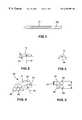
- FIG. 1is a wound down, helical coil stent under strain
- FIG. 2is a strand with an unstrained radius curvature
- FIG. 3is a strand with a strained radius curvature
- FIG. 4is a bundle of strands
- FIG. 5is a cross-section of a four stranded bundle with worst case stacking
- FIG. 6is an helical coil stent
- FIG. 7is a detail of the helical coil stent of FIG. 6 using a four stranded cross-over braid;
- FIG. 8is a cross-section of the detail of the bundle of FIG. 7;
- FIG. 9is a three stranded braid
- FIG. 10is a four stranded cross-over braid
- FIG. 11is a five stranded braid
- FIG. 12is a six stranded round braid
- FIG. 13is an alternate six stranded flat braid
- FIG. 14is an eight stranded alternating braid
- FIG. 15is an eight stranded braid
- FIG. 16is an eight stranded twisted braid
- FIG. 17is a nine stranded double braid
- FIG. 18is an eleven stranded braid
- FIG. 19is an eleven stranded alternating braid
- FIG. 20is a twelve stranded cross-over braid.
- a helical coil stent 10is deformed into a reduced diameter 30 .
- This deformationimposes a strain in the stent material. If the strain is too great, the stent 10 will experience plastic deformation to such an extent that the stent will not recover dimensionally to the specified size during deployment.
- the strain experienced by the stent 10 materialis proportional to the thickness 35 of the stent material.
- the present inventionapplies to any helical coil stent 10 where deformation is limited by the applied strain.
- the stent 10is formed of multiple strands 15 . Each strand is continuous and discrete. Multiple strands 15 of material are formed into a bundle 40 , each strand 15 having a fine thickness.
- the resulting hoop strength of the stent 10 formed of one or more bundles 40will be the cumulative strength of all of the strands 15 in the bundle(s) 40 .
- the strainon the other hand, will be limited to that of a single strand 15 .
- Bundles 40can be formed by braiding or by other means to enable the strands 15 to slide relative to one another when compressed or released; this is necessary to reduce friction. One or more bundles 40 are then formed into the elongate hollow tubular stent 10 .
- the increased deformation capacity of multiple strands 15 which are formed into a bundle 40is possible because strain is proportional to a single strand 15 thickness, not the thickness of the bundle 40 of strands 15 .
- the width of the braided bundle 40 of strandsis significantly greater than that of a round wire. Multiple strands 15 braided together into a bundle 40 provide support to one another, providing resistance to lateral forces as well as to crushing forces. By increasing the number of strands 15 in the braid, the width can be increased resulting in greater lateral strength. The increase in the number of strands 15 also provides increased radial or “hoop” strength.
- the braided wire coil stent 10provides a means to deliver a decreased profile stent while still providing accurate deployment thereby resulting in a less traumatic stent 10 delivery.
- stent 10 deformationwill increase when assembling the stent 10 onto a smaller delivery catheter.
- a limitwill be reached where the following parameters can be optimized no further and the strand 15 thickness can no longer realistically be reduced. These parameters include the delivery catheter size, the hoop strength, the lateral strength.
- the preferred number of strands 15would be unique from one stent application to another. Any number of three or more strands would be possible.
- a larger diameter 20 stent 10would generally require more strands 15 than a smaller diameter 20 stent 10 to provide adequate radial and hoop strength.
- a stent 10might require more strands 15 to increase the resistance to compression, as in a stent 10 intended for implantation in the popliteal artery.
- Some stents 10might require fewer strands 15 to minimize the amount of blood contact with metal.
- Others, such as a biliary stentwould require more strands 15 or a flatter braid pattern to provide total coverage of the orifice being stented to prevent tissue in-growth.
- the balloon expandable stent 10can be made of a round wire or of a flat wire using a springy, inert, biocompatible material with high corrosion resistance that can be plastically deformed at low-moderate stress levels. Acceptable materials include tantalum, stainless steel or elgiloy.
- the preferred embodiment for a self-expanding stent 10includes superelastic (nickel titanium) NiTi such as Nitinol manufactured by Raychem or Forukawa. Any of the braided patterns could be made from a round wire or from a flat wire.
- FIGS. 4-5 and FIGS. 7-20depict braided stents of 3 - 6 strands, 8 - 9 strands, and 11 - 12 strands with alternative 6 (FIGS. 12 and 13 ), alternative 8 (FIGS. 14 and 16) and alternative 11 (FIGS. 18 and 19) stranded embodiments.
- Those skilled in the artwould recognize that these examples are not the only braided patterns that could be used for the bundle of strands stent concept. Potentially any braid pattern could be used, as for example, a seven or a ten stranded braid.
- the braidis a flattened braid which is formed into a stent 10 with a flat side of the braid forming the stent cylinder so as to minimize the delivered profile of the stent and to maximize the luminal diameter of the stent.
- the helical coil stent 10could be formed by affixing the ends of the desired length of strands 15 to each other and wrapping the braided bundle 40 around a conventional mandrel to form the desired diameter 20 .
- the endscan be affixed with any welding technique such as, plasma welding, laser welding, RF welding or TIG welding.
- brazing, soldering or crimpingcould be employed to affix the stent ends to each other.
- the helical coil shapecan be “memory set” into the braided bundle 40 .
- Stents 10are placed in a strained state (see FIGS. 1 and 3) during the assembly process where the stents 10 are taken from a free unstrained state (see FIGS. 6 and 2) and are wound onto a delivery catheter 105 at a much smaller diameter.
- a braided bundle 40is formed into a helical coil, the strands 15 may shift with respect to each other. Induced strain is higher when strands 15 stack exactly on top of each other as in FIG. 5 and less if the strands are offset as in FIG. 4 .
- Strainis highest at the inner edge of the stent coil while in the assembled state (see FIG. 1) and can be represented by the following equation:
- R 1is the unstrained radius of curvature 25
- R 2is the strained radius of curvature 30
- dis the wire strand 35 thickness (wire diameter depending on whether the strand is round or flat) as opposed to the overall stent 10 diameter.
- Three stent designswill be mathematically approximated to, for the smallest diameter stent 10 that can be wound down on a delivery catheter without exceeding the 8% strain permitted with Nitinol as the metal. These examples show that the smallest delivery profile achievable is that of a braided multi strand 15 stent 10 . All three stents have a nominal outer diameter of 9 mm (0.354 inches) and it is assumed will provide adequate hoop and lateral strength. The material in each example is Nitinol which has a maximum 8% allowable strain.
- the first exampleis a helical coil stent 10 formed from a single member round 0.013 inch wire.
- a 9 mm outer diameter 20 stent 10requires a round wire with a minimum diameter of 0.013 inches to provide the necessary hoop strength and lateral stiffness.
- the applied strainis 8%.
- the unstrained radius of ad curvature 25is 0.1705 inches and the outer diameter of the strand 15 is 0.013 inches.
- the second exampleis a 9 mm outer diameter 20 helical coil stent 10 formed from a single strand 10 of 0.008 inch ⁇ 0.025 inch flat wire. This size wire is wide enough to provide lateral stability which is lost when the thickness of the wire is reduced to 0.008 inches.
- the unstrained radius of curvature 25is 0.173 inches and the outer diameter 20 is 0.008 inches.
- the strained radius of curvature 30is therefor 0.087 inches.
- the stentsdid not return to the nominal diameters following deployment as they were undersized, a function of the flattening process during the raw wire manufacture.
- the maximum stent device outer diameter 20 profileis 0.067 inches, with at least a 5.1 French introducer size.
- the third exampleis a helical coil stent 10 formed from multiple braided 0.005 inch strands 15 , as for example five strands 15 seen in FIG. 4 or four strands 15 seen in FIG. 5 .
- R 20.267 the outer diameter
- Braided bundles 40can be of any number of strands.
- FIG. 9is a three stranded braid. Each strand 15 could be a bundle 40 with one to four or more strands.
- FIG. 10is a four stranded cross-over braid. Each strand 15 could be a bundle 40 with one to four or more strands.
- FIG. 11is a five stranded braid.
- FIG. 12is a six stranded round braid.
- FIG. 13is a six stranded flat braid.
- FIG. 14is an eight stranded alternating braid.
- FIG. 15is an eight stranded braid.
- FIG. 16is an eight stranded twisted braid.
- FIG. 17is a nine stranded double braid.
- FIG. 18is an eleven stranded braid.
- FIG. 19is an eleven stranded alternating braid which is braided in the same pattern as the eight stranded FIG. 14 but using three additional strands. Any number of strands, however, could be used in this alternating pattern.
- FIG. 20is a twelve stranded cross-over braid made with four bundles 40 with three strands 15 each and braided in the pattern of FIG. 10 . Any number of strands could be used in the bundle(s).
Landscapes
- Health & Medical Sciences (AREA)
- Engineering & Computer Science (AREA)
- Biomedical Technology (AREA)
- Cardiology (AREA)
- Oral & Maxillofacial Surgery (AREA)
- Transplantation (AREA)
- Heart & Thoracic Surgery (AREA)
- Vascular Medicine (AREA)
- Life Sciences & Earth Sciences (AREA)
- Animal Behavior & Ethology (AREA)
- General Health & Medical Sciences (AREA)
- Public Health (AREA)
- Veterinary Medicine (AREA)
- Media Introduction/Drainage Providing Device (AREA)
Abstract
Description
| No. | |
| 10 | |
| 15 | Strand |
| 20 | D - Outer Diameter of Stent |
| 25 | R1- Unstrained Radius of Curvature |
| 30 | R2- Strained Radius of Curvature |
| 35 | d - |
| 40 | |
| 45 | Strand 1 |
| 50 | Strand 2 |
| 55 | Strand 3 |
| 60 | Strand 4 |
| 65 | Strand 5 |
| 70 | Strand 6 |
| 75 | Strand 7 |
| 80 | |
| 85 | Strand 9 |
| 90 | |
| 95 | Strand 11 |
| 100 | Strand 12 |
| 105 | |
| 110 | |
| 115 | |
| 120 | Third Bundle |
| 125 | Fourth Bundle |
Claims (10)
Priority Applications (3)
| Application Number | Priority Date | Filing Date | Title |
|---|---|---|---|
| US09/067,665US6494907B1 (en) | 1998-04-28 | 1998-04-28 | Braided stent |
| PCT/US1999/009142WO1999055256A1 (en) | 1998-04-28 | 1999-04-28 | Braided stent |
| AU37664/99AAU3766499A (en) | 1998-04-28 | 1999-04-28 | Braided stent |
Applications Claiming Priority (1)
| Application Number | Priority Date | Filing Date | Title |
|---|---|---|---|
| US09/067,665US6494907B1 (en) | 1998-04-28 | 1998-04-28 | Braided stent |
Publications (1)
| Publication Number | Publication Date |
|---|---|
| US6494907B1true US6494907B1 (en) | 2002-12-17 |
Family
ID=22077550
Family Applications (1)
| Application Number | Title | Priority Date | Filing Date |
|---|---|---|---|
| US09/067,665Expired - LifetimeUS6494907B1 (en) | 1998-04-28 | 1998-04-28 | Braided stent |
Country Status (3)
| Country | Link |
|---|---|
| US (1) | US6494907B1 (en) |
| AU (1) | AU3766499A (en) |
| WO (1) | WO1999055256A1 (en) |
Cited By (62)
| Publication number | Priority date | Publication date | Assignee | Title |
|---|---|---|---|---|
| US20030055479A1 (en)* | 1999-11-16 | 2003-03-20 | Iowa-India Investments Company, Limited | Encapsulated stent preform |
| US20040073293A1 (en)* | 1996-04-30 | 2004-04-15 | Thompson Paul J. | Three-dimensional braided covered stent |
| US20040153118A1 (en)* | 2003-01-30 | 2004-08-05 | Clubb Thomas L. | Embolic filters having multiple layers and controlled pore size |
| US20040153117A1 (en)* | 2003-01-30 | 2004-08-05 | Clubb Thomas L. | Embolic filters with controlled pore size |
| US20040167436A1 (en)* | 2003-02-26 | 2004-08-26 | Reynolds Brian R. | Elongate medical device with distal cap |
| US20040193141A1 (en)* | 2003-02-14 | 2004-09-30 | Leopold Eric W. | Intravascular flow modifier and reinforcement device and deployment system for same |
| US20040193246A1 (en)* | 2003-03-25 | 2004-09-30 | Microvention, Inc. | Methods and apparatus for treating aneurysms and other vascular defects |
| US20060167490A1 (en)* | 2003-01-30 | 2006-07-27 | Ev3 Inc. | Embolic filters with a distal loop or no loop |
| US7147660B2 (en) | 2001-12-20 | 2006-12-12 | Boston Scientific Santa Rosa Corp. | Advanced endovascular graft |
| US7147661B2 (en) | 2001-12-20 | 2006-12-12 | Boston Scientific Santa Rosa Corp. | Radially expandable stent |
| US7204847B1 (en)* | 2000-07-28 | 2007-04-17 | C. R. Bard, Inc. | Implant anchor systems |
| US20080200945A1 (en)* | 2004-03-19 | 2008-08-21 | Aga Medical Corporation | Device for occluding vascular defects |
| US20080228028A1 (en)* | 2007-03-12 | 2008-09-18 | Cook Incorporated | Woven fabric with shape memory element strands |
| DE102009052002A1 (en)* | 2009-11-05 | 2011-05-19 | Acandis Gmbh & Co. Kg | A medical device for recanalizing body cavities and set comprising such device |
| US7955351B2 (en) | 2005-02-18 | 2011-06-07 | Tyco Healthcare Group Lp | Rapid exchange catheters and embolic protection devices |
| US20110190886A1 (en)* | 2010-01-29 | 2011-08-04 | Wisconsin Alumni Research Foundation | Braided tertiary nanofibrous structure for ligament, tendon, and muscle tissue implant |
| US8066755B2 (en) | 2007-09-26 | 2011-11-29 | Trivascular, Inc. | System and method of pivoted stent deployment |
| US8083789B2 (en) | 2007-11-16 | 2011-12-27 | Trivascular, Inc. | Securement assembly and method for expandable endovascular device |
| US8226701B2 (en) | 2007-09-26 | 2012-07-24 | Trivascular, Inc. | Stent and delivery system for deployment thereof |
| US8328861B2 (en) | 2007-11-16 | 2012-12-11 | Trivascular, Inc. | Delivery system and method for bifurcated graft |
| US8388679B2 (en) | 2007-01-19 | 2013-03-05 | Maquet Cardiovascular Llc | Single continuous piece prosthetic tubular aortic conduit and method for manufacturing the same |
| US8398670B2 (en) | 2004-03-19 | 2013-03-19 | Aga Medical Corporation | Multi-layer braided structures for occluding vascular defects and for occluding fluid flow through portions of the vasculature of the body |
| US8663309B2 (en) | 2007-09-26 | 2014-03-04 | Trivascular, Inc. | Asymmetric stent apparatus and method |
| US8696741B2 (en) | 2010-12-23 | 2014-04-15 | Maquet Cardiovascular Llc | Woven prosthesis and method for manufacturing the same |
| US8747453B2 (en)* | 2008-02-18 | 2014-06-10 | Aga Medical Corporation | Stent/stent graft for reinforcement of vascular abnormalities and associated method |
| US8777974B2 (en) | 2004-03-19 | 2014-07-15 | Aga Medical Corporation | Multi-layer braided structures for occluding vascular defects |
| US8834552B2 (en) | 2007-12-27 | 2014-09-16 | Cook Medical Technologies Llc | Stent graft having floating yarns |
| US8992595B2 (en) | 2012-04-04 | 2015-03-31 | Trivascular, Inc. | Durable stent graft with tapered struts and stable delivery methods and devices |
| US9023094B2 (en) | 2007-06-25 | 2015-05-05 | Microvention, Inc. | Self-expanding prosthesis |
| US9039724B2 (en) | 2004-03-19 | 2015-05-26 | Aga Medical Corporation | Device for occluding vascular defects |
| US20150238336A1 (en)* | 2013-08-27 | 2015-08-27 | Covidien Lp | Delivery of medical devices |
| US9498363B2 (en) | 2012-04-06 | 2016-11-22 | Trivascular, Inc. | Delivery catheter for endovascular device |
| WO2017127692A1 (en)* | 2016-01-22 | 2017-07-27 | Fort Wayne Metals Research Products Corp. | Woven or braided tubular metal construct |
| US9782186B2 (en) | 2013-08-27 | 2017-10-10 | Covidien Lp | Vascular intervention system |
| USRE46662E1 (en)* | 2004-09-17 | 2018-01-09 | DePuy Synthes Products, Inc. | Vascular occlusion device with an embolic mesh ribbon |
| CN108430396A (en)* | 2015-10-30 | 2018-08-21 | 波士顿科学国际有限公司 | Implantable medical device with binding region |
| US10111670B2 (en) | 2015-05-01 | 2018-10-30 | DePuy Synthes Products, Inc. | Expandable vascular occlusion device with lead framing coil |
| US10159557B2 (en) | 2007-10-04 | 2018-12-25 | Trivascular, Inc. | Modular vascular graft for low profile percutaneous delivery |
| CN109350306A (en)* | 2018-11-21 | 2019-02-19 | 杭州嘉和众邦生物科技有限公司 | A kind of the valve frame and its manufacturing method of surgical implantation type bioprosthetic valves |
| US10213290B2 (en) | 2016-02-17 | 2019-02-26 | Boston Scientific Scimed, Inc. | Braided stent and method of manufacturing a braided stent |
| US10314635B2 (en) | 2014-05-28 | 2019-06-11 | A&E Advanced Closure Systems, Llc | Tensioning instruments |
| CN109893311A (en)* | 2018-12-07 | 2019-06-18 | 上海百心安生物技术有限公司 | A kind of novel biodegradable stent and its manufacturing method |
| US10376396B2 (en) | 2017-01-19 | 2019-08-13 | Covidien Lp | Coupling units for medical device delivery systems |
| US10426532B2 (en) | 2012-11-21 | 2019-10-01 | A&E Advanced Closure Systems, Llc | Bone plate system and method |
| US10456283B2 (en) | 2016-07-13 | 2019-10-29 | Boston Scientific Scimed, Inc. | Apparatus and method for maintaining patency in a vessel adjacent to nearby surgery |
| US10463410B2 (en) | 2016-01-22 | 2019-11-05 | A&E Advanced Closure Systems, Llc | Bone plate having a connector and a connector for a surgical loop |
| US10485600B2 (en) | 2016-07-29 | 2019-11-26 | A&E Advanced Closure Systems, Llc | Surgical cable tensioner |
| US10537452B2 (en) | 2012-02-23 | 2020-01-21 | Covidien Lp | Luminal stenting |
| US10765465B2 (en) | 2012-11-21 | 2020-09-08 | A&E Advanced Closure Systems, Llc | Tensioning instrument |
| US10786377B2 (en) | 2018-04-12 | 2020-09-29 | Covidien Lp | Medical device delivery |
| US10881437B2 (en) | 2013-12-05 | 2021-01-05 | A&E Advanced Closure Systems, Llc | Bone plate system and method |
| US11071637B2 (en) | 2018-04-12 | 2021-07-27 | Covidien Lp | Medical device delivery |
| US11123209B2 (en) | 2018-04-12 | 2021-09-21 | Covidien Lp | Medical device delivery |
| US11266517B2 (en) | 2018-04-09 | 2022-03-08 | Boston Scientific Scimed, Inc. | Stent |
| US11413176B2 (en) | 2018-04-12 | 2022-08-16 | Covidien Lp | Medical device delivery |
| US11413174B2 (en) | 2019-06-26 | 2022-08-16 | Covidien Lp | Core assembly for medical device delivery systems |
| US11559412B2 (en) | 2019-01-07 | 2023-01-24 | Boston Scientific Scimed, Inc. | Stent with anti-migration feature |
| US11918496B2 (en) | 2020-12-02 | 2024-03-05 | Boston Scientific Scimed, Inc. | Stent with improved deployment characteristics |
| US11944558B2 (en) | 2021-08-05 | 2024-04-02 | Covidien Lp | Medical device delivery devices, systems, and methods |
| US12042413B2 (en) | 2021-04-07 | 2024-07-23 | Covidien Lp | Delivery of medical devices |
| US12109137B2 (en) | 2021-07-30 | 2024-10-08 | Covidien Lp | Medical device delivery |
| US12329665B2 (en) | 2020-09-29 | 2025-06-17 | Boston Scientific Scimed, Inc. | Stent with anti-migration features |
Families Citing this family (19)
| Publication number | Priority date | Publication date | Assignee | Title |
|---|---|---|---|---|
| GB9828696D0 (en) | 1998-12-29 | 1999-02-17 | Houston J G | Blood-flow tubing |
| US6368346B1 (en) | 1999-06-03 | 2002-04-09 | American Medical Systems, Inc. | Bioresorbable stent |
| IL140869A0 (en) | 2001-01-11 | 2002-02-10 | Mind Guard Ltd | Implantable expanding stroke preventing device and method of maufacturing |
| US6325822B1 (en) | 2000-01-31 | 2001-12-04 | Scimed Life Systems, Inc. | Braided stent having tapered filaments |
| US6622604B1 (en)* | 2000-01-31 | 2003-09-23 | Scimed Life Systems, Inc. | Process for manufacturing a braided bifurcated stent |
| US6398807B1 (en) | 2000-01-31 | 2002-06-04 | Scimed Life Systems, Inc. | Braided branching stent, method for treating a lumen therewith, and process for manufacture therefor |
| US6652571B1 (en) | 2000-01-31 | 2003-11-25 | Scimed Life Systems, Inc. | Braided, branched, implantable device and processes for manufacture thereof |
| IL137326A0 (en) | 2000-07-17 | 2001-07-24 | Mind Guard Ltd | Implantable braided stroke preventing device and method of manufacturing |
| BE1013757A6 (en)* | 2000-12-12 | 2002-07-02 | Frid Noureddine | Luminal endoprosthesis MODULAR. |
| US8192484B2 (en) | 2000-12-12 | 2012-06-05 | Cardiatis S.A. | Stent for blood flow improvement |
| GB2369797B (en)* | 2001-11-20 | 2002-11-06 | Tayside Flow Technologies Ltd | Helical formations in tubes |
| USD567946S1 (en) | 2003-05-29 | 2008-04-29 | Tayside Flow Technologies Limited | Vascular tube |
| USD524442S1 (en) | 2003-05-29 | 2006-07-04 | Tayside Flow Technologies Limited | Vascular tube |
| GB0315714D0 (en) | 2003-07-04 | 2003-08-13 | Tayside Flow Technologies Ltd | An internal formation for a conduit |
| DE102008036429A1 (en)* | 2008-08-05 | 2010-02-11 | Acandis Gmbh & Co. Kg | Medical implant |
| DE102009042121B3 (en)* | 2009-09-18 | 2011-04-21 | Acandis Gmbh & Co. Kg | Medical device for insertion into a hollow body organ |
| US8353952B2 (en) | 2010-04-07 | 2013-01-15 | Medtronic Vascular, Inc. | Stent with therapeutic substance |
| DE102010048368A1 (en)* | 2010-10-13 | 2012-04-19 | Acandis Gmbh & Co. Kg | Medical device, in particular stent |
| CN115153953B (en)* | 2022-09-08 | 2023-01-03 | 深圳市华和创微医疗科技有限公司 | Three-dimensional braided stent and manufacturing method |
Citations (41)
| Publication number | Priority date | Publication date | Assignee | Title |
|---|---|---|---|---|
| US3868956A (en) | 1972-06-05 | 1975-03-04 | Ralph J Alfidi | Vessel implantable appliance and method of implanting it |
| EP0122744A1 (en) | 1983-04-04 | 1984-10-24 | Pfizer Hospital Products Group, Inc. | Triaxially-braided fabric prosthesis |
| US4517687A (en) | 1982-09-15 | 1985-05-21 | Meadox Medicals, Inc. | Synthetic woven double-velour graft |
| US4530113A (en) | 1983-05-20 | 1985-07-23 | Intervascular, Inc. | Vascular grafts with cross-weave patterns |
| US4553545A (en) | 1981-09-16 | 1985-11-19 | Medinvent S.A. | Device for application in blood vessels or other difficultly accessible locations and its use |
| US4649922A (en) | 1986-01-23 | 1987-03-17 | Wiktor Donimik M | Catheter arrangement having a variable diameter tip and spring prosthesis |
| US4655771A (en) | 1982-04-30 | 1987-04-07 | Shepherd Patents S.A. | Prosthesis comprising an expansible or contractile tubular body |
| US4760849A (en) | 1985-04-10 | 1988-08-02 | Medinvent S.A. | Planar blank and a coil spring manufactured therefrom |
| US4771773A (en) | 1985-06-10 | 1988-09-20 | Medinvent S.A. | Insertion device |
| US4851009A (en) | 1985-12-16 | 1989-07-25 | Corvita Corporation | Crack prevention of implanted prostheses |
| US4886062A (en) | 1987-10-19 | 1989-12-12 | Medtronic, Inc. | Intravascular radially expandable stent and method of implant |
| US4969458A (en) | 1987-07-06 | 1990-11-13 | Medtronic, Inc. | Intracoronary stent and method of simultaneous angioplasty and stent implant |
| WO1991012779A1 (en) | 1990-02-28 | 1991-09-05 | Medtronic, Inc. | Intralumenal drug eluting prosthesis |
| US5057092A (en) | 1990-04-04 | 1991-10-15 | Webster Wilton W Jr | Braided catheter with low modulus warp |
| US5061275A (en) | 1986-04-21 | 1991-10-29 | Medinvent S.A. | Self-expanding prosthesis |
| US5064435A (en) | 1990-06-28 | 1991-11-12 | Schneider (Usa) Inc. | Self-expanding prosthesis having stable axial length |
| US5217495A (en)* | 1989-05-10 | 1993-06-08 | United States Surgical Corporation | Synthetic semiabsorbable composite yarn |
| US5342348A (en) | 1992-12-04 | 1994-08-30 | Kaplan Aaron V | Method and device for treating and enlarging body lumens |
| US5366504A (en) | 1992-05-20 | 1994-11-22 | Boston Scientific Corporation | Tubular medical prosthesis |
| US5370682A (en)* | 1993-04-26 | 1994-12-06 | Meadox Medicals, Inc. | Solid woven tubular prosthesis |
| US5372600A (en) | 1991-10-31 | 1994-12-13 | Instent Inc. | Stent delivery systems |
| US5449372A (en) | 1990-10-09 | 1995-09-12 | Scimed Lifesystems, Inc. | Temporary stent and methods for use and manufacture |
| WO1995029646A1 (en) | 1994-04-29 | 1995-11-09 | Boston Scientific Corporation | Medical prosthetic stent and method of manufacture |
| US5545208A (en)* | 1990-02-28 | 1996-08-13 | Medtronic, Inc. | Intralumenal drug eluting prosthesis |
| EP0740928A2 (en) | 1995-04-12 | 1996-11-06 | Corvita Europe | Self-expanding stent for introducing a medical device in a body cavity and manufacturing process |
| DE19516060A1 (en) | 1995-05-04 | 1996-11-07 | Feichtinger Heinrich K | Endo-vascular implant for influencing blood-flow characteristics |
| US5575818A (en) | 1995-02-14 | 1996-11-19 | Corvita Corporation | Endovascular stent with locking ring |
| US5591222A (en) | 1991-10-18 | 1997-01-07 | Susawa; Takashi | Method of manufacturing a device to dilate ducts in vivo |
| US5597378A (en) | 1983-10-14 | 1997-01-28 | Raychem Corporation | Medical devices incorporating SIM alloy elements |
| US5618298A (en) | 1993-10-23 | 1997-04-08 | Simon; Michael | Vascular prosthesis made of resorbable material |
| WO1997013475A1 (en) | 1995-10-11 | 1997-04-17 | Schneider (Usa) Inc. | Braided composite prosthesis |
| US5632746A (en) | 1989-08-16 | 1997-05-27 | Medtronic, Inc. | Device or apparatus for manipulating matter |
| US5645559A (en) | 1992-05-08 | 1997-07-08 | Schneider (Usa) Inc | Multiple layer stent |
| WO1997025002A1 (en) | 1996-01-05 | 1997-07-17 | Medtronic, Inc. | Expansible endoluminal prostheses |
| WO1997025000A1 (en) | 1996-01-04 | 1997-07-17 | Endo Vascular Technologies, Inc | Flat wire stent |
| US5718159A (en) | 1996-04-30 | 1998-02-17 | Schneider (Usa) Inc. | Process for manufacturing three-dimensional braided covered stent |
| US5749919A (en)* | 1994-01-10 | 1998-05-12 | Microfil Industries S.A. | Resilient prosthesis for widening a channel, particularly a blood vessel, and method for making same |
| US5893867A (en)* | 1996-11-06 | 1999-04-13 | Percusurge, Inc. | Stent positioning apparatus and method |
| US5961547A (en)* | 1995-06-22 | 1999-10-05 | Ali Razavi | Temporary stent |
| US5964797A (en)* | 1996-08-30 | 1999-10-12 | Target Therapeutics, Inc. | Electrolytically deployable braided vaso-occlusion device |
| US6241691B1 (en)* | 1997-12-05 | 2001-06-05 | Micrus Corporation | Coated superelastic stent |
- 1998
- 1998-04-28USUS09/067,665patent/US6494907B1/ennot_activeExpired - Lifetime
- 1999
- 1999-04-28WOPCT/US1999/009142patent/WO1999055256A1/enactiveApplication Filing
- 1999-04-28AUAU37664/99Apatent/AU3766499A/ennot_activeAbandoned
Patent Citations (45)
| Publication number | Priority date | Publication date | Assignee | Title |
|---|---|---|---|---|
| US3868956A (en) | 1972-06-05 | 1975-03-04 | Ralph J Alfidi | Vessel implantable appliance and method of implanting it |
| US4553545A (en) | 1981-09-16 | 1985-11-19 | Medinvent S.A. | Device for application in blood vessels or other difficultly accessible locations and its use |
| US4655771A (en) | 1982-04-30 | 1987-04-07 | Shepherd Patents S.A. | Prosthesis comprising an expansible or contractile tubular body |
| US4655771B1 (en) | 1982-04-30 | 1996-09-10 | Medinvent Ams Sa | Prosthesis comprising an expansible or contractile tubular body |
| US4517687A (en) | 1982-09-15 | 1985-05-21 | Meadox Medicals, Inc. | Synthetic woven double-velour graft |
| EP0122744A1 (en) | 1983-04-04 | 1984-10-24 | Pfizer Hospital Products Group, Inc. | Triaxially-braided fabric prosthesis |
| US4530113A (en) | 1983-05-20 | 1985-07-23 | Intervascular, Inc. | Vascular grafts with cross-weave patterns |
| US5597378A (en) | 1983-10-14 | 1997-01-28 | Raychem Corporation | Medical devices incorporating SIM alloy elements |
| US4760849A (en) | 1985-04-10 | 1988-08-02 | Medinvent S.A. | Planar blank and a coil spring manufactured therefrom |
| US4771773A (en) | 1985-06-10 | 1988-09-20 | Medinvent S.A. | Insertion device |
| US4851009A (en) | 1985-12-16 | 1989-07-25 | Corvita Corporation | Crack prevention of implanted prostheses |
| US4649922A (en) | 1986-01-23 | 1987-03-17 | Wiktor Donimik M | Catheter arrangement having a variable diameter tip and spring prosthesis |
| US5061275A (en) | 1986-04-21 | 1991-10-29 | Medinvent S.A. | Self-expanding prosthesis |
| US4969458A (en) | 1987-07-06 | 1990-11-13 | Medtronic, Inc. | Intracoronary stent and method of simultaneous angioplasty and stent implant |
| US4886062A (en) | 1987-10-19 | 1989-12-12 | Medtronic, Inc. | Intravascular radially expandable stent and method of implant |
| US5217495A (en)* | 1989-05-10 | 1993-06-08 | United States Surgical Corporation | Synthetic semiabsorbable composite yarn |
| US5632746A (en) | 1989-08-16 | 1997-05-27 | Medtronic, Inc. | Device or apparatus for manipulating matter |
| US5871535A (en)* | 1990-02-28 | 1999-02-16 | Medtronic, Inc. | Intralumenal drug eluting prosthesis |
| WO1991012779A1 (en) | 1990-02-28 | 1991-09-05 | Medtronic, Inc. | Intralumenal drug eluting prosthesis |
| US5545208A (en)* | 1990-02-28 | 1996-08-13 | Medtronic, Inc. | Intralumenal drug eluting prosthesis |
| US5057092A (en) | 1990-04-04 | 1991-10-15 | Webster Wilton W Jr | Braided catheter with low modulus warp |
| US5064435A (en) | 1990-06-28 | 1991-11-12 | Schneider (Usa) Inc. | Self-expanding prosthesis having stable axial length |
| US5449372A (en) | 1990-10-09 | 1995-09-12 | Scimed Lifesystems, Inc. | Temporary stent and methods for use and manufacture |
| US5591222A (en) | 1991-10-18 | 1997-01-07 | Susawa; Takashi | Method of manufacturing a device to dilate ducts in vivo |
| US5372600A (en) | 1991-10-31 | 1994-12-13 | Instent Inc. | Stent delivery systems |
| US5645559A (en) | 1992-05-08 | 1997-07-08 | Schneider (Usa) Inc | Multiple layer stent |
| US5674276A (en) | 1992-05-20 | 1997-10-07 | Boston Scientific Corporation | Tubular medical prosthesis |
| US5366504A (en) | 1992-05-20 | 1994-11-22 | Boston Scientific Corporation | Tubular medical prosthesis |
| US5342348A (en) | 1992-12-04 | 1994-08-30 | Kaplan Aaron V | Method and device for treating and enlarging body lumens |
| US5370682A (en)* | 1993-04-26 | 1994-12-06 | Meadox Medicals, Inc. | Solid woven tubular prosthesis |
| US5618298A (en) | 1993-10-23 | 1997-04-08 | Simon; Michael | Vascular prosthesis made of resorbable material |
| US5749919A (en)* | 1994-01-10 | 1998-05-12 | Microfil Industries S.A. | Resilient prosthesis for widening a channel, particularly a blood vessel, and method for making same |
| WO1995029646A1 (en) | 1994-04-29 | 1995-11-09 | Boston Scientific Corporation | Medical prosthetic stent and method of manufacture |
| US5575818A (en) | 1995-02-14 | 1996-11-19 | Corvita Corporation | Endovascular stent with locking ring |
| EP0740928A2 (en) | 1995-04-12 | 1996-11-06 | Corvita Europe | Self-expanding stent for introducing a medical device in a body cavity and manufacturing process |
| DE19516060A1 (en) | 1995-05-04 | 1996-11-07 | Feichtinger Heinrich K | Endo-vascular implant for influencing blood-flow characteristics |
| US5961547A (en)* | 1995-06-22 | 1999-10-05 | Ali Razavi | Temporary stent |
| US5758562A (en)* | 1995-10-11 | 1998-06-02 | Schneider (Usa) Inc. | Process for manufacturing braided composite prosthesis |
| WO1997013475A1 (en) | 1995-10-11 | 1997-04-17 | Schneider (Usa) Inc. | Braided composite prosthesis |
| WO1997025000A1 (en) | 1996-01-04 | 1997-07-17 | Endo Vascular Technologies, Inc | Flat wire stent |
| WO1997025002A1 (en) | 1996-01-05 | 1997-07-17 | Medtronic, Inc. | Expansible endoluminal prostheses |
| US5718159A (en) | 1996-04-30 | 1998-02-17 | Schneider (Usa) Inc. | Process for manufacturing three-dimensional braided covered stent |
| US5964797A (en)* | 1996-08-30 | 1999-10-12 | Target Therapeutics, Inc. | Electrolytically deployable braided vaso-occlusion device |
| US5893867A (en)* | 1996-11-06 | 1999-04-13 | Percusurge, Inc. | Stent positioning apparatus and method |
| US6241691B1 (en)* | 1997-12-05 | 2001-06-05 | Micrus Corporation | Coated superelastic stent |
Non-Patent Citations (1)
| Title |
|---|
| Braidmaking by Barbara Pegg, Published 1990, A&C Black Publishers Ltd., London pp. 9-17. |
Cited By (119)
| Publication number | Priority date | Publication date | Assignee | Title |
|---|---|---|---|---|
| US7052513B2 (en) | 1996-04-30 | 2006-05-30 | Boston Scientific Scimed, Inc. | Three-dimensional braided covered stent |
| US20040073293A1 (en)* | 1996-04-30 | 2004-04-15 | Thompson Paul J. | Three-dimensional braided covered stent |
| US6746478B2 (en)* | 1999-11-16 | 2004-06-08 | Vascular Concepts Holdings Limited | Stent formed from encapsulated stent preforms |
| US20030055479A1 (en)* | 1999-11-16 | 2003-03-20 | Iowa-India Investments Company, Limited | Encapsulated stent preform |
| US7204847B1 (en)* | 2000-07-28 | 2007-04-17 | C. R. Bard, Inc. | Implant anchor systems |
| US7147661B2 (en) | 2001-12-20 | 2006-12-12 | Boston Scientific Santa Rosa Corp. | Radially expandable stent |
| US7147660B2 (en) | 2001-12-20 | 2006-12-12 | Boston Scientific Santa Rosa Corp. | Advanced endovascular graft |
| US7323001B2 (en) | 2003-01-30 | 2008-01-29 | Ev3 Inc. | Embolic filters with controlled pore size |
| US20070135834A1 (en)* | 2003-01-30 | 2007-06-14 | Ev3 Inc. | Embolic filters with controlled pore size |
| US8137376B2 (en) | 2003-01-30 | 2012-03-20 | Tyco Healthcare Group Lp | Embolic filters having multiple layers and controlled pore size |
| US20060167490A1 (en)* | 2003-01-30 | 2006-07-27 | Ev3 Inc. | Embolic filters with a distal loop or no loop |
| US8409242B2 (en) | 2003-01-30 | 2013-04-02 | Covidien Lp | Embolic filters with controlled pore size |
| US20040153118A1 (en)* | 2003-01-30 | 2004-08-05 | Clubb Thomas L. | Embolic filters having multiple layers and controlled pore size |
| US9603692B2 (en) | 2003-01-30 | 2017-03-28 | Covidien Lp | Embolic filters with controlled pore size |
| US20040153117A1 (en)* | 2003-01-30 | 2004-08-05 | Clubb Thomas L. | Embolic filters with controlled pore size |
| US7220271B2 (en) | 2003-01-30 | 2007-05-22 | Ev3 Inc. | Embolic filters having multiple layers and controlled pore size |
| WO2004069098A3 (en)* | 2003-01-30 | 2004-10-21 | Ev3 Inc | Embolic filters with controlled pore size |
| US9011478B2 (en) | 2003-01-30 | 2015-04-21 | Covidien Lp | Embolic filters with a distal loop or no loop |
| US20070198051A1 (en)* | 2003-01-30 | 2007-08-23 | Ev3 Inc. | Embolic filters having multiple layers and controlled pore size |
| US20080021535A1 (en)* | 2003-02-14 | 2008-01-24 | Micrus Corporation, A Delaware Corporation | Intravascular Flow Modifier And Reinforcement Device And Deployment System For Same |
| US8398700B2 (en) | 2003-02-14 | 2013-03-19 | Micrus Corporation | Intravascular flow modifier and reinforcement device and deployment system for same |
| US20040193141A1 (en)* | 2003-02-14 | 2004-09-30 | Leopold Eric W. | Intravascular flow modifier and reinforcement device and deployment system for same |
| US20040167436A1 (en)* | 2003-02-26 | 2004-08-26 | Reynolds Brian R. | Elongate medical device with distal cap |
| US20070114211A1 (en)* | 2003-02-26 | 2007-05-24 | Boston Scientific Scimed, Inc. | Elongated medical device with distal cap |
| US7169118B2 (en) | 2003-02-26 | 2007-01-30 | Scimed Life Systems, Inc. | Elongate medical device with distal cap |
| US8022331B2 (en) | 2003-02-26 | 2011-09-20 | Boston Scientific Scimed, Inc. | Method of making elongated medical devices |
| US20040193246A1 (en)* | 2003-03-25 | 2004-09-30 | Microvention, Inc. | Methods and apparatus for treating aneurysms and other vascular defects |
| US9445798B2 (en) | 2004-03-19 | 2016-09-20 | St. Jude Medical, Cardiology Division, Inc. | Multi-layer braided structures for occluding vascular defects |
| US11134933B2 (en) | 2004-03-19 | 2021-10-05 | St. Jude Medical, Cardiology Division, Inc. | Multi-layer braided structures for occluding vascular defects |
| US9877710B2 (en) | 2004-03-19 | 2018-01-30 | St. Jude Medical, Cardiology Division, Inc. | Multi-layer braided structures for occluding vascular defects and for occluding fluid flow through portions of the vasculature of the body |
| US8313505B2 (en) | 2004-03-19 | 2012-11-20 | Aga Medical Corporation | Device for occluding vascular defects |
| US9445799B2 (en) | 2004-03-19 | 2016-09-20 | St. Jude Medical, Cardiology Division, Inc. | Multi-layer braided structures for occluding vascular defects |
| US9039724B2 (en) | 2004-03-19 | 2015-05-26 | Aga Medical Corporation | Device for occluding vascular defects |
| US8398670B2 (en) | 2004-03-19 | 2013-03-19 | Aga Medical Corporation | Multi-layer braided structures for occluding vascular defects and for occluding fluid flow through portions of the vasculature of the body |
| US20080200945A1 (en)* | 2004-03-19 | 2008-08-21 | Aga Medical Corporation | Device for occluding vascular defects |
| US8777974B2 (en) | 2004-03-19 | 2014-07-15 | Aga Medical Corporation | Multi-layer braided structures for occluding vascular defects |
| USRE46662E1 (en)* | 2004-09-17 | 2018-01-09 | DePuy Synthes Products, Inc. | Vascular occlusion device with an embolic mesh ribbon |
| US7955351B2 (en) | 2005-02-18 | 2011-06-07 | Tyco Healthcare Group Lp | Rapid exchange catheters and embolic protection devices |
| US9456889B2 (en) | 2005-02-18 | 2016-10-04 | Covidien Lp | Rapid exchange catheters and embolic protection devices |
| US10537418B2 (en) | 2005-02-18 | 2020-01-21 | Covidien Lp | Rapid exchange catheters and embolic protection devices |
| US8388679B2 (en) | 2007-01-19 | 2013-03-05 | Maquet Cardiovascular Llc | Single continuous piece prosthetic tubular aortic conduit and method for manufacturing the same |
| US8940041B2 (en) | 2007-03-12 | 2015-01-27 | Cook Medical Technologies Llc | Woven fabric with shape memory element strands |
| US20080228028A1 (en)* | 2007-03-12 | 2008-09-18 | Cook Incorporated | Woven fabric with shape memory element strands |
| US8177834B2 (en)* | 2007-03-12 | 2012-05-15 | Cook Medical Technologies Llc | Woven fabric with shape memory element strands |
| US9427342B2 (en) | 2007-03-12 | 2016-08-30 | Cook Medical Technologies Llc | Woven fabric with shape memory element strands |
| US9023094B2 (en) | 2007-06-25 | 2015-05-05 | Microvention, Inc. | Self-expanding prosthesis |
| US8226701B2 (en) | 2007-09-26 | 2012-07-24 | Trivascular, Inc. | Stent and delivery system for deployment thereof |
| US8066755B2 (en) | 2007-09-26 | 2011-11-29 | Trivascular, Inc. | System and method of pivoted stent deployment |
| US8663309B2 (en) | 2007-09-26 | 2014-03-04 | Trivascular, Inc. | Asymmetric stent apparatus and method |
| US10682222B2 (en) | 2007-10-04 | 2020-06-16 | Trivascular, Inc. | Modular vascular graft for low profile percutaneous delivery |
| US10159557B2 (en) | 2007-10-04 | 2018-12-25 | Trivascular, Inc. | Modular vascular graft for low profile percutaneous delivery |
| US12016766B2 (en) | 2007-10-04 | 2024-06-25 | Trivascular, Inc. | Modular vascular graft for low profile percutaneous delivery |
| US8083789B2 (en) | 2007-11-16 | 2011-12-27 | Trivascular, Inc. | Securement assembly and method for expandable endovascular device |
| US8328861B2 (en) | 2007-11-16 | 2012-12-11 | Trivascular, Inc. | Delivery system and method for bifurcated graft |
| US8834552B2 (en) | 2007-12-27 | 2014-09-16 | Cook Medical Technologies Llc | Stent graft having floating yarns |
| US8747453B2 (en)* | 2008-02-18 | 2014-06-10 | Aga Medical Corporation | Stent/stent graft for reinforcement of vascular abnormalities and associated method |
| DE102009052002B4 (en)* | 2009-11-05 | 2012-09-27 | Acandis Gmbh & Co. Kg | A medical device for recanalizing body cavities and set comprising such device |
| DE102009052002A1 (en)* | 2009-11-05 | 2011-05-19 | Acandis Gmbh & Co. Kg | A medical device for recanalizing body cavities and set comprising such device |
| US20110190886A1 (en)* | 2010-01-29 | 2011-08-04 | Wisconsin Alumni Research Foundation | Braided tertiary nanofibrous structure for ligament, tendon, and muscle tissue implant |
| US9402753B2 (en) | 2010-12-23 | 2016-08-02 | Maquet Cardiovascular Llc | Woven prosthesis and method for manufacturing the same |
| US11517417B2 (en) | 2010-12-23 | 2022-12-06 | Maquet Cardiovascular Llc | Woven prosthesis and method for manufacturing the same |
| US10010401B2 (en) | 2010-12-23 | 2018-07-03 | Maquet Cardiovascular Llc | Woven prosthesis and method for manufacturing the same |
| US10682221B2 (en) | 2010-12-23 | 2020-06-16 | Maquet Cardiovascular Llc | Woven prosthesis and method for manufacturing the same |
| US8696741B2 (en) | 2010-12-23 | 2014-04-15 | Maquet Cardiovascular Llc | Woven prosthesis and method for manufacturing the same |
| US11259946B2 (en) | 2012-02-23 | 2022-03-01 | Covidien Lp | Luminal stenting |
| US10537452B2 (en) | 2012-02-23 | 2020-01-21 | Covidien Lp | Luminal stenting |
| US8992595B2 (en) | 2012-04-04 | 2015-03-31 | Trivascular, Inc. | Durable stent graft with tapered struts and stable delivery methods and devices |
| US9498363B2 (en) | 2012-04-06 | 2016-11-22 | Trivascular, Inc. | Delivery catheter for endovascular device |
| US10765465B2 (en) | 2012-11-21 | 2020-09-08 | A&E Advanced Closure Systems, Llc | Tensioning instrument |
| US10426532B2 (en) | 2012-11-21 | 2019-10-01 | A&E Advanced Closure Systems, Llc | Bone plate system and method |
| US9782186B2 (en) | 2013-08-27 | 2017-10-10 | Covidien Lp | Vascular intervention system |
| US9827126B2 (en) | 2013-08-27 | 2017-11-28 | Covidien Lp | Delivery of medical devices |
| US10265207B2 (en) | 2013-08-27 | 2019-04-23 | Covidien Lp | Delivery of medical devices |
| US10045867B2 (en) | 2013-08-27 | 2018-08-14 | Covidien Lp | Delivery of medical devices |
| US12343273B2 (en) | 2013-08-27 | 2025-07-01 | Covidien Lp | Delivery of medical devices |
| US20150238336A1 (en)* | 2013-08-27 | 2015-08-27 | Covidien Lp | Delivery of medical devices |
| US10695204B2 (en) | 2013-08-27 | 2020-06-30 | Covidien Lp | Delivery of medical devices |
| US11076972B2 (en) | 2013-08-27 | 2021-08-03 | Covidien Lp | Delivery of medical devices |
| US9775733B2 (en)* | 2013-08-27 | 2017-10-03 | Covidien Lp | Delivery of medical devices |
| US10092431B2 (en) | 2013-08-27 | 2018-10-09 | Covidien Lp | Delivery of medical devices |
| US11103374B2 (en) | 2013-08-27 | 2021-08-31 | Covidien Lp | Delivery of medical devices |
| US10881437B2 (en) | 2013-12-05 | 2021-01-05 | A&E Advanced Closure Systems, Llc | Bone plate system and method |
| US11298172B2 (en) | 2014-05-28 | 2022-04-12 | A&E Advanced Closure Systems, Llc | Tensioning instruments |
| US10314635B2 (en) | 2014-05-28 | 2019-06-11 | A&E Advanced Closure Systems, Llc | Tensioning instruments |
| US10111670B2 (en) | 2015-05-01 | 2018-10-30 | DePuy Synthes Products, Inc. | Expandable vascular occlusion device with lead framing coil |
| US11376010B2 (en) | 2015-05-01 | 2022-07-05 | DePuy Synthes Products, Inc. | Expandable vascular occlusion device with lead framing coil |
| US10939917B2 (en) | 2015-05-01 | 2021-03-09 | DePuy Synthes Products, Inc. | Expandable vascular occlusion device with lead framing coil |
| CN108430396A (en)* | 2015-10-30 | 2018-08-21 | 波士顿科学国际有限公司 | Implantable medical device with binding region |
| US11497538B2 (en) | 2016-01-22 | 2022-11-15 | Fort Wayne Metals Research Products, Llc | Woven or braided tubular metal construct |
| US10463410B2 (en) | 2016-01-22 | 2019-11-05 | A&E Advanced Closure Systems, Llc | Bone plate having a connector and a connector for a surgical loop |
| WO2017127692A1 (en)* | 2016-01-22 | 2017-07-27 | Fort Wayne Metals Research Products Corp. | Woven or braided tubular metal construct |
| CN108738305A (en)* | 2016-01-22 | 2018-11-02 | 韦恩堡金属研究产品公司 | Woven or Braided Tubular Metal Construction |
| US11413077B2 (en) | 2016-01-22 | 2022-08-16 | A&E Advanced Closure Systems, Llc | Bone plate having a connector and a connector for a surgical loop |
| US10213290B2 (en) | 2016-02-17 | 2019-02-26 | Boston Scientific Scimed, Inc. | Braided stent and method of manufacturing a braided stent |
| US10456283B2 (en) | 2016-07-13 | 2019-10-29 | Boston Scientific Scimed, Inc. | Apparatus and method for maintaining patency in a vessel adjacent to nearby surgery |
| US10485600B2 (en) | 2016-07-29 | 2019-11-26 | A&E Advanced Closure Systems, Llc | Surgical cable tensioner |
| US11833069B2 (en) | 2017-01-19 | 2023-12-05 | Covidien Lp | Coupling units for medical device delivery systems |
| US10376396B2 (en) | 2017-01-19 | 2019-08-13 | Covidien Lp | Coupling units for medical device delivery systems |
| US10945867B2 (en) | 2017-01-19 | 2021-03-16 | Covidien Lp | Coupling units for medical device delivery systems |
| US11986407B2 (en) | 2018-04-09 | 2024-05-21 | Boston Scientific Scimed, Inc. | Stent |
| US12213899B2 (en) | 2018-04-09 | 2025-02-04 | Boston Scientific Scimed, Inc. | Stent |
| US11266517B2 (en) | 2018-04-09 | 2022-03-08 | Boston Scientific Scimed, Inc. | Stent |
| US12419765B2 (en) | 2018-04-09 | 2025-09-23 | Boston Scientific Scimed, Inc. | Stent |
| US11890212B2 (en) | 2018-04-09 | 2024-02-06 | Boston Scientific Scimed, Inc. | Stent |
| US11413176B2 (en) | 2018-04-12 | 2022-08-16 | Covidien Lp | Medical device delivery |
| US11648140B2 (en) | 2018-04-12 | 2023-05-16 | Covidien Lp | Medical device delivery |
| US11071637B2 (en) | 2018-04-12 | 2021-07-27 | Covidien Lp | Medical device delivery |
| US10786377B2 (en) | 2018-04-12 | 2020-09-29 | Covidien Lp | Medical device delivery |
| US11123209B2 (en) | 2018-04-12 | 2021-09-21 | Covidien Lp | Medical device delivery |
| CN109350306B (en)* | 2018-11-21 | 2024-03-08 | 杭州创心医学科技有限公司 | Surgical implantation type biological valve frame and manufacturing method thereof |
| CN109350306A (en)* | 2018-11-21 | 2019-02-19 | 杭州嘉和众邦生物科技有限公司 | A kind of the valve frame and its manufacturing method of surgical implantation type bioprosthetic valves |
| CN109893311A (en)* | 2018-12-07 | 2019-06-18 | 上海百心安生物技术有限公司 | A kind of novel biodegradable stent and its manufacturing method |
| US11559412B2 (en) | 2019-01-07 | 2023-01-24 | Boston Scientific Scimed, Inc. | Stent with anti-migration feature |
| US11413174B2 (en) | 2019-06-26 | 2022-08-16 | Covidien Lp | Core assembly for medical device delivery systems |
| US12329665B2 (en) | 2020-09-29 | 2025-06-17 | Boston Scientific Scimed, Inc. | Stent with anti-migration features |
| US11918496B2 (en) | 2020-12-02 | 2024-03-05 | Boston Scientific Scimed, Inc. | Stent with improved deployment characteristics |
| US12042413B2 (en) | 2021-04-07 | 2024-07-23 | Covidien Lp | Delivery of medical devices |
| US12109137B2 (en) | 2021-07-30 | 2024-10-08 | Covidien Lp | Medical device delivery |
| US11944558B2 (en) | 2021-08-05 | 2024-04-02 | Covidien Lp | Medical device delivery devices, systems, and methods |
Also Published As
| Publication number | Publication date |
|---|---|
| AU3766499A (en) | 1999-11-16 |
| WO1999055256A1 (en) | 1999-11-04 |
Similar Documents
| Publication | Publication Date | Title |
|---|---|---|
| US6494907B1 (en) | Braided stent | |
| US5913896A (en) | Interwoven dual sinusoidal helix stent | |
| US5591198A (en) | Multiple sinusoidal wave configuration stent | |
| US5843168A (en) | Double wave stent with strut | |
| EP1389069B1 (en) | Expandable coil stent | |
| US5899934A (en) | Dual stent | |
| US5613981A (en) | Bidirectional dual sinusoidal helix stent | |
| US6730116B1 (en) | Medical device for intraluminal endovascular stenting | |
| EP1093771B1 (en) | Flexible medical stent | |
| US7108714B1 (en) | Expandable intraluminal endoprosthesis | |
| JP4278874B2 (en) | Stent having struts with different geometric shapes | |
| US6432132B1 (en) | Expandable intraluminal endoprosthesis | |
| EP1565129B1 (en) | Expandable stents | |
| EP0969777B1 (en) | Coiled sheet stent having helical articulation and methods of use | |
| EP1155664B1 (en) | A helical stent having flat ends | |
| US6117165A (en) | Expandable intraluminal endoprosthesis | |
| EP1208814A2 (en) | Low profile stent | |
| US20110054589A1 (en) | Stent with variable cross section braiding filament and method for making same | |
| CA2223502A1 (en) | Bifurcated endovascular stent | |
| EP1492471A1 (en) | Hybrid stent | |
| US20210378849A1 (en) | Stent with Enhanced Low Crimping Profile | |
| US20090149945A1 (en) | Prosthetic support for flaccid arterial segments | |
| EP0799607A2 (en) | Intravascular stent having flattened profile |
Legal Events
| Date | Code | Title | Description |
|---|---|---|---|
| AS | Assignment | Owner name:MEDTRONIC, INC., MINNESOTA Free format text:ASSIGNMENT OF ASSIGNORS INTEREST;ASSIGNOR:BULVER, JULIE M.;REEL/FRAME:009141/0512 Effective date:19980428 | |
| AS | Assignment | Owner name:INTRATHERAPEUTICS, INC, MINNESOTA Free format text:CERTIFICATE OF OWNERSHIP AND MERGER;ASSIGNOR:INTRATHERAPEUTICS WEST, INC;REEL/FRAME:010359/0661 Effective date:19990430 Owner name:INTRATHERAPEUTICS WEST, INC., MINNESOTA Free format text:CHANGE OF NAME AND CERTIFICATE OF AMENDMENT OF CERTIFICATE OF INCORPORATION;ASSIGNOR:MEDTRONIC INSTENT, INC.;REEL/FRAME:010359/0697 Effective date:19981125 | |
| AS | Assignment | Owner name:MEDTRONIC INSTENT, INC., MINNESOTA Free format text:ASSIGNMENT OF ASSIGNORS INTEREST;ASSIGNOR:MEDTRONIC, INC.;REEL/FRAME:010364/0810 Effective date:19981030 | |
| STCF | Information on status: patent grant | Free format text:PATENTED CASE | |
| AS | Assignment | Owner name:EV3 PERIPHERAL, INC., MINNESOTA Free format text:CHANGE OF NAME;ASSIGNOR:SULZER INTRATHERAPEUTICS, INC.;REEL/FRAME:014327/0092 Effective date:20021227 Owner name:SULZER INTRA THERAPEUTICS, INC., MINNESOTA Free format text:CHANGE OF NAME;ASSIGNOR:INTRA THERAPEUTICS, INC.;REEL/FRAME:014337/0413 Effective date:20010201 | |
| FPAY | Fee payment | Year of fee payment:4 | |
| FPAY | Fee payment | Year of fee payment:8 | |
| FPAY | Fee payment | Year of fee payment:12 |