US6494892B1 - Disposable hub for a surgical cutting instrument - Google Patents
Disposable hub for a surgical cutting instrumentDownload PDFInfo
- Publication number
- US6494892B1 US6494892B1US09/335,153US33515399AUS6494892B1US 6494892 B1US6494892 B1US 6494892B1US 33515399 AUS33515399 AUS 33515399AUS 6494892 B1US6494892 B1US 6494892B1
- Authority
- US
- United States
- Prior art keywords
- hub
- disposed
- lock member
- connection portion
- cutting
- Prior art date
- Legal status (The legal status is an assumption and is not a legal conclusion. Google has not performed a legal analysis and makes no representation as to the accuracy of the status listed.)
- Expired - Lifetime
Links
Images


Classifications
- A—HUMAN NECESSITIES
- A61—MEDICAL OR VETERINARY SCIENCE; HYGIENE
- A61F—FILTERS IMPLANTABLE INTO BLOOD VESSELS; PROSTHESES; DEVICES PROVIDING PATENCY TO, OR PREVENTING COLLAPSING OF, TUBULAR STRUCTURES OF THE BODY, e.g. STENTS; ORTHOPAEDIC, NURSING OR CONTRACEPTIVE DEVICES; FOMENTATION; TREATMENT OR PROTECTION OF EYES OR EARS; BANDAGES, DRESSINGS OR ABSORBENT PADS; FIRST-AID KITS
- A61F9/00—Methods or devices for treatment of the eyes; Devices for putting in contact-lenses; Devices to correct squinting; Apparatus to guide the blind; Protective devices for the eyes, carried on the body or in the hand
- A61F9/007—Methods or devices for eye surgery
- A61F9/00736—Instruments for removal of intra-ocular material or intra-ocular injection, e.g. cataract instruments
- A61F9/00763—Instruments for removal of intra-ocular material or intra-ocular injection, e.g. cataract instruments with rotating or reciprocating cutting elements, e.g. concentric cutting needles
- A—HUMAN NECESSITIES
- A61—MEDICAL OR VETERINARY SCIENCE; HYGIENE
- A61B—DIAGNOSIS; SURGERY; IDENTIFICATION
- A61B17/00—Surgical instruments, devices or methods
- A61B17/16—Instruments for performing osteoclasis; Drills or chisels for bones; Trepans
- A61B17/1613—Component parts
- A61B17/162—Chucks or tool parts which are to be held in a chuck
- A—HUMAN NECESSITIES
- A61—MEDICAL OR VETERINARY SCIENCE; HYGIENE
- A61B—DIAGNOSIS; SURGERY; IDENTIFICATION
- A61B17/00—Surgical instruments, devices or methods
- A61B17/16—Instruments for performing osteoclasis; Drills or chisels for bones; Trepans
- A61B17/1613—Component parts
- A61B17/1633—Sleeves, i.e. non-rotating parts surrounding the bit shaft, e.g. the sleeve forming a single unit with the bit shaft
- A—HUMAN NECESSITIES
- A61—MEDICAL OR VETERINARY SCIENCE; HYGIENE
- A61B—DIAGNOSIS; SURGERY; IDENTIFICATION
- A61B17/00—Surgical instruments, devices or methods
- A61B2017/0023—Surgical instruments, devices or methods disposable
- A—HUMAN NECESSITIES
- A61—MEDICAL OR VETERINARY SCIENCE; HYGIENE
- A61B—DIAGNOSIS; SURGERY; IDENTIFICATION
- A61B17/00—Surgical instruments, devices or methods
- A61B2017/00477—Coupling
Definitions
- the present inventionrelates to minimally invasive surgical instruments for the incision and removable of a wide range of tissues. Specifically, the invention concerns disposable surgical cutting assemblies for operative engagement with powered hand-pieces.
- any incomplete cutting of the fiberscould create retinal traction which could lead to retinal detachment. Incomplete cutting may result from a dull cutting blade, wherein the blade would merely pull the fibers and increase the retinal traction, or from a poor interface of the cutting edges of the outer needle and the cutting blade wherein the shearing effect of the edges passing across one another is reduced.
- imperfect alignment of the cutting blade within the outer tubecould cause the shearing action to be localized at the center of the cutting edges and prevent the outer portion of the cutting edges from interfacing sufficiently close enough for a clean shearing action to occur.
- an inner cutting sleeveis operated within the central bore of an outer cutting sleeve.
- the outer sleevedefines one or more apertures for receiving tissue when suction is applied.
- the inner sleevecan be reciprocated or rotated within the outer sleeve to pass a cutting edge past the aperture to cut tissue.
- Disposable devices and/or sterilization proceduresare employed.
- disposable bladescan be coupled with reusable, sterilizable hand-pieces.
- the disposable surgical bladesare connectable to a hand-piece through a locking collar, spring, and key and groove arrangement.
- locking collars and other componentscan become contaminated with tissue, preventing proper function of the connection mechanism.
- a surgical cutting instrumentincludes a hollow hub having a working portion, which terminates at a working end and a connection portion, which terminates at a connection end.
- the connection portiondefines a cavity and a lock member which projects from an outer surface of the connection portion.
- An outer tubular memberextends from the working end and is sized for insertion into an anatomical space.
- the outer tubular memberdefines a central bore along the length I of the outer tubular member.
- the outer tubular memberhas a proximal end attached to the working end of the hub and a distal end.
- the outer tubular memberfurther defines a cutting opening adjacent the distal end and sized to receive tissue therethrough.
- a cutting memberis slidably disposed within the central bore of the outer tubular member.
- the cutting memberhas a first operational end, which defines a cutting head, and a second engagement end disposed within the cavity of the hub.
- a drive elementis also disposed within the cavity and has a drive mount portion connected to the engagement end of the cutting member.
- the drive elementfurther has a mating portion operationally connectable to a source of motion. The drive element translates motion from the source of motion to the cutting member to move the cutting member relative to the outer tubular member so the cutting head traverses the cutting opening.
- the instrumentincludes a powered hand-piece having a source of motion and an outer shell, which defines an outer gripping portion.
- a hollow hub connectoris provided within the handpiece.
- the connectorhas a cylindrical wall with a hand-piece connection portion and a hub engagement portion.
- the connection portionis disposed within and is connected to the hand-piece.
- the hub engagement portiondefines a chamber for receiving the connection portion of the hub.
- the chamberhas a longitudinal axis A L parallel to the length of the hub connector.
- the hub engagement portionfurther defines a channel through the cylindrical wall for receiving the lock member.
- the channelis in communication with the chamber.
- the channelhas a longitudinal section defined in the wall parallel to the length L of the connector.
- the channelalso has a second transverse section communicating with the longitudinal section.
- a locking recessis defined in the wall perpendicularly to the transverse section, and in communication with the opposite end of the transverse section. The locking recess is sized to receive the lock member.
- connection portion of the hubis slidable within the chamber along the longitudinal axis when the lock member is disposed within the longitudinal section of the channel.
- the connection portion of the hubis rotatable within the chamber when the lock member is disposed within the transverse section of the channel.
- the connection portion of the hubis fixed within the chamber when the lock member is disposed within the locking recess.
- the inventionin another embodiment, includes a spring element disposed on the connection portion of the hub.
- the spring elementurges the lock member into the locking recess wherein the locking member is rotated into the opposite end of the transverse section of the channel.
- the spring elementhas a squeezed position when the lock member is in the transverse section of the channel and a rest position when the lock member is in the locking recess.
- the spring elementis a beam spring disposed at the connection end of the hub.
- the beam springincludes a beam having a first face adjacent the connection end and a second opposite face with a boss projecting from the opposite face.
- the instrumentin still another aspect of the invention, includes a drive connector disposed within the chamber of the hub connector.
- the drive connectoris operably engageable to the source of motion and releasably matable to the mating portion of the drive element when the hub is engaged to the hub connector.
- the mating portionincludes a transverse bar disposed within the cavity of the hub and the drive connector includes a bayonet element matable to the transverse bar.
- the bayonet elementhas a pair of spaced arms each terminating in a hook.
- the bayonet elementis configured to releasably receive the transverse bar when the hub is disposed within the chamber and the lock members received within the longitudinal channel. When the hub is rotated the locking member is disposed within the locking recess, the transverse bar is captured by the hooks to thereby operatively engage the inner tubular member to the source of motion.
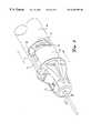
- FIG. 1is a side perspective view of one embodiment of a cutter assembly according to this invention.
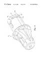
- FIG. 2is a partial sectional view of a surgical cutter including the hub assembly shown in FIG. 1 .
- FIG. 3is a perspective view of a hub according to one embodiment of this invention.
- FIG. 4is a side sectional view of a cutter assembly of this invention.
- FIG. 5is a side sectional view of a cutter assembly of this invention.
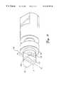
- FIG. 6is a perspective view of one embodiment of a hub connector.
- FIG. 7is an exploded perspective view of a hub and connector assembly according to one embodiment of this invention.
- FIG. 8is a side perspective view of a cutter assembly of this invention with the locking member of the hub at the junction of the longitudinal and transverse sections of the channel of the hub connector.
- FIG. 9is a perspective view of a hub according to one embodiment of this invention.
- FIG. 10is a partial sectional exploded view of the cutter assembly shown in FIG. 1 .
- FIG. 11is a side elevational view of a drive connector according to one embodiment of the present invention.
- the present inventionprovides a surgical cutting instrument 10 in accordance with the preferred embodiment of the invention as depicted in FIGS. 1 and 2.
- the instrument 10includes a disposable surgical cutting assembly 11 operatively connected to a powered hand-piece 40 , which is connected to a source of power such as by electrical cable 41 .
- the disposable assembly 11includes a hollow hub 15 having a working portion 16 terminating at a working end 17 and a connection portion 18 terminating at a connection end 19 as depicted in FIG. 3 .
- the connection portion 18defines a cavity 20 and includes a lock member 22 projecting from an outer surface 21 of the connection portion 18 .
- the disposable assembly 11includes a disposable surgical cutting element
- the disposable surgical elementincludes a surgical cutter of the “tube within a tube” type such as the reciprocating and rotary cutters known in the art.
- the disposable surgical cutting elementincludes an outer tubular member 30 sized for insertion into an anatomical space.
- the outer tubular member 30defines a central bore 31 along the length I of the outer tubular member 30 .
- the outer tubular member 30has a proximal end 32 attached to the working end 17 of the hub 15 and a distal end 33 .
- the outer tubular member 30 of this embodimentdefines a cutting opening 34 adjacent the distal end 33 that is sized to receive tissue therethrough.
- the cutting opening 34has a first cutting edge, such as is disclosed in the Miller patent, U.S. Pat. No. 5,782,849, the entire disclosure of which is hereby incorporated by reference.
- the cutting opening 34is oval shaped; however, any suitably shaped cutting opening is contemplated by this invention.
- the surgical cutting elementincludes an inner tubular member or cutting member 35 slidably disposed within the central bore 31 of the outer tubular member 30 .
- the cutting member 35has a first operational end 36 defining a cutting head 37 and a second engagement end 38 disposed proximal to or within the cavity 20 of the hub 15 .
- the tubular members of this inventionmay have various features that enhance their function.
- the inner tubular member 35 shown in FIG. 4includes a hinge 36 a connecting the cutting edge portion 37 to the body of the cutting member 35 to permit pivoting of the cutting head 37 relative to the rest of the cutting member 35 .
- the cutting head 37contacts tissue drawn into the cutting opening. Resistance from the tissue causes the cutting head 37 to pivot about the hinge to form an essentially zero clearance between the cutting head 37 and the cutting opening 34 of the outer tubular member 30 , as is disclosed in U.S. Pat. No. 5,782,849 to Miller.
- the disposable assembly 11also includes a drive element 50 disposed within the cavity 20 of the hub 15 .
- the drive element 50has a drive mount portion 52 connected to the engagement end 38 of the inner cutting member 35 and a mating portion 55 operationally connectable to a source of motion.
- the drive element 50translates motion from a source of motion, such as a motor, to the cutting member 35 to move the cutting member 35 relative to the outer tubular member 30 so that the cutting head 37 traverses the cutting opening 34 .
- a source of motionsuch as a motor
- the mating portion 55includes a transverse bar 56 that is operatively matable to an element engaged to the source of mating.
- the drive element 50is engaged to the hub by projections 51 that are positioned within slots 24 defined in the hub 15 . In this embodiment, as the drive element 50 reciprocates and the projection 51 travels between the proximal end 25 and the distal end 26 of the slot 24 .
- the disposable surgical cutting assembly 11also includes a hollow hub connector 60 having a length L and a cylindrical wall 61 as shown in FIGS. 2 and 6.
- the hub connector 60includes, in some embodiments, a hand-piece connection portion 62 that is the hand-piece 40 or preferably, is insertable into a shell 45 having a gripping portion 46 to form the hand-piece.
- the hub connectors of this inventionmay include hand-piece connection portions 62 ' that have various features 66 , 67 , 68 that facilitate engagement of the hub connector 60 ' to the hand-piece 40 or the shell 45 .
- the connector 60also includes a hub engagement portion 65 defining a chamber 70 for receiving the connection portion 18 of the hub.
- the chamber 70has a longitudinal axis A L that is parallel to the length L of the hub connector 60 .
- the hub engagement portion 65further defines a channel 75 through the cylindrical wall 61 for receiving the lock member 22 when the hub 15 is disposed within the chamber 70 .
- the channel 75is in communication with the chamber 70 and has an essentially truncated J shape.
- Channel 75has a first longitudinal section 76 defined along the length L of the connector 60 .
- a second transverse section 77communicates with the longitudinal section 76 at junction 80 .
- the transverse section 77has a first end 78 adjacent the junction 80 and an opposite second end 79 .
- a locking recess 81is defined through the wall 62 perpendicular to the transverse section 77 and communicates with the opposite end 79 of the transverse section 17 .
- the locking recess 81is sized to receive and retain the lock member 22 .
- the particular size and configuration of the locking recess 81will be determined by the configuration of the locking member 22 and the particular application of the disposable assembly 11 .
- the locking recess 81is deep enough to retain the locking member 22 during operation of the instrument but shallow enough that the hub can be disengaged by hand
- connection portion 18 of the hub 15is slidable within the chamber 70 along the longitudinal axis A L of the chamber when the lock member 22 is disposed within the longitudinal section 76 of the channel 75 .
- connection portion 18 of the hub 15is rotatable within the chamber 70 , but not slidable along the axis A L when the lock member 22 is disposed within the transverse section 77 of the channel 75 .
- the hub 15is fixed relative to the hub connector 60 when the lock member 22 is disposed within the locking recess 81 as shown in FIG. 1 .
- the disposable assembly 11also preferably includes a spring element that operates to urge the lock member 22 into the lock member recess 81 when the locking member 22 is rotated into the opposite end 79 of the transverse section 77 of the channel 75 .
- the spring elementmost preferably is a beam spring 100 disposed at the connection end 19 of the hub 15 .
- the beam spring 100includes a first beam 101 having a first face 102 adjacent the connection end 19 and a second opposite face 103 .
- the spring elementalso includes a boss 105 projecting from the opposite face 103 of each of the beams 101 .
- the spring elementmay include any number of beams 101 and the embodiments depicted include a pair of beams 101 .
- the lock member 22When the hub 15 is fully inserted into the chamber 70 of the hub connector 60 the lock member 22 bottoms out in the longitudinal section 76 of the channel 75 and the lock member is disposed within the junction 80 of the longitudinal section 76 and the transverse section 77 . In this position, a force F must be exerted in the direction of the arrow F to depress the spring into the squeezed position so that the locking member 22 may enter the transverse section 77 of the channel 75 .
- the boss 105acts against a spring platform 130 disposed within the hub connector 60 or hand-piece 40 .
- the spring platformis located at a spring-loaded distance from the transverse channel 77 .
- the platform 130can constitute a surface of the transverse channel 77 or can be a reduced diameter surface formed on wall 61 , for example.
- the spring elementis resilient enough to be forced into a squeezed position when the lock member 22 is rotated into the transverse section 27 of the channel 75 and a force F is exerted to depress the spring.
- the force S of the springis overcome by the action of the edge 23 of the lock member 22 on the trap surface 77 a of the transverse section.
- the surgical cutting instruments 10 of this inventioninclude a drive connector 120 disposed within the chamber 70 of the hub connector 60 .
- Other arrangementsare contemplated so long as the drive connector 120 is matable to the mating portion 55 of the drive element 50 when the hub 15 is engaged to the hub connector 60 .
- the drive connector 120is operably engageable to the source of motion.
- the mating portion 55 of the drive element 50 and the drive connector 120will be complementary so that the disposable assembly can be releasably matable.
- the drive connector 120includes a bayonet element 125 that is releasably matable to the transverse bar. As shown in FIG.
- the bayonet element 125includes a pair of spaced arms 126 , 128 each terminating in a hook 127 , 129 .
- the bayonet element 125is configured to releasably receive the transverse bar 56 when the hub 15 is disposed within the chamber 70 of the hub connector 60 and the lock member 22 is received within the longitudinal section 76 of the channel 75 .
- the bayonet element 125will capture the transverse bar 56 when the hub 15 is rotated in the direction of arrow R so that the locking member 22 of the hub 15 is disposed within the locking recess 81 .
- the arms 126 , 128are preferably spaced and parallel to form a gap g between the hooks 127 , 129 .
- the gap ghas a longitudinal axis A g .
- the gapis sized for releasably receiving the transverse bar 56 when the bar 56 is disposed within the gap g with the length l b (FIG. 4) of the bar 56 along the longitudinal axis A g of the gap g.
- the bayonet element 125 of this inventionpreferably is provided with a spring platform 130 adjacent the bayonet element 125 and spaced from the hooks 127 , 129 at a spring loaded distance d for the spring element
- the instruments of this inventionalso include various features to facilitate the excision of tissue.
- an aspiration tube 140is disposed within a slot 27 defined in the hub 15 .
- the aspiration tube 140is connected to a suitable vacuum source and tissue collection chamber in a manner well known in the art.
- the devices of this inventionare made from any suitable material, preferably an economical material that makes single use of the disposable components economically feasible.
- the hubs 15 , spring elements 100 and drive mechanismsare preferably formed of molded plastic.
- the molded plasticis polycarbonate, or the like.
- any suitable plastic that is sterilization compatible and structurally stableis contemplated.
- the needles 30 , 35are preferably composed of surgical grade stainless steel.
- the outer cannula 30had a length of 1.220 inches from the proximal end 32 to the distal end 33 with a total length of 1.335 inches with a diameter of about 0.050 inches or less.
- the inner cutter 35had a length of 1.941 inches from the operational end 36 to the engagement end 38 with a diameter of about 0.040 inches.
- the drive element 50had a maximum width of 0.315 inches including the projections 51 and a minimum width of 0.226 inches and a height of 0.047 inches.
- the drive spring 13had an outer diameter of 0.170 inches.
- the hub 15had a length of about 1.01 including the beam spring 100 and each boss 105 was about 0.025 inches.
- the lock member 22had a height of about 1 mm.
- Each beam 101had a length of about 0.041 inches separated by a 0.050 inch cut-away from the hub body 15 .
- the major diameter of the hub 15was 0.510 inches.
- the present inventionprovides disposable surgical cutting assemblies that can be used with powered hand-pieces that are commercially available.
- the assemblies of this inventionprovide an elegant connection mechanism that requires minimal components thus reducing the risk of device malfunction and preventing incorrect connection of the blade to the power source. Proper connection of the disposable component is also assured because all of the moving parts of the assembled surgical cutting instrument are contained within the disposable component.
Landscapes
- Health & Medical Sciences (AREA)
- Ophthalmology & Optometry (AREA)
- Heart & Thoracic Surgery (AREA)
- Surgery (AREA)
- Engineering & Computer Science (AREA)
- Biomedical Technology (AREA)
- Nuclear Medicine, Radiotherapy & Molecular Imaging (AREA)
- Vascular Medicine (AREA)
- Life Sciences & Earth Sciences (AREA)
- Animal Behavior & Ethology (AREA)
- General Health & Medical Sciences (AREA)
- Public Health (AREA)
- Veterinary Medicine (AREA)
- Surgical Instruments (AREA)
Abstract
Description
Claims (11)
Priority Applications (1)
| Application Number | Priority Date | Filing Date | Title |
|---|---|---|---|
| US09/335,153US6494892B1 (en) | 1998-10-20 | 1999-06-17 | Disposable hub for a surgical cutting instrument |
Applications Claiming Priority (2)
| Application Number | Priority Date | Filing Date | Title |
|---|---|---|---|
| US17549198A | 1998-10-20 | 1998-10-20 | |
| US09/335,153US6494892B1 (en) | 1998-10-20 | 1999-06-17 | Disposable hub for a surgical cutting instrument |
Related Parent Applications (1)
| Application Number | Title | Priority Date | Filing Date |
|---|---|---|---|
| US17549198AContinuation | 1998-10-20 | 1998-10-20 |
Publications (1)
| Publication Number | Publication Date |
|---|---|
| US6494892B1true US6494892B1 (en) | 2002-12-17 |
Family
ID=22640428
Family Applications (1)
| Application Number | Title | Priority Date | Filing Date |
|---|---|---|---|
| US09/335,153Expired - LifetimeUS6494892B1 (en) | 1998-10-20 | 1999-06-17 | Disposable hub for a surgical cutting instrument |
Country Status (1)
| Country | Link |
|---|---|
| US (1) | US6494892B1 (en) |
Cited By (80)
| Publication number | Priority date | Publication date | Assignee | Title |
|---|---|---|---|---|
| USD484243S1 (en) | 2002-03-22 | 2003-12-23 | Gyrus Ent L.L.C. | Surgical tool blade holder |
| USD484595S1 (en) | 2002-03-22 | 2003-12-30 | Gyrus Ent L.L.C. | Surgical tool blade holder |
| USD484596S1 (en) | 2002-03-22 | 2003-12-30 | Gyrus Ent L.L.C. | Surgical tool blade holder |
| USD484977S1 (en) | 2002-03-22 | 2004-01-06 | Gyrus Ent L.L.C. | Surgical tool blade holder |
| US20060241665A1 (en)* | 2005-04-08 | 2006-10-26 | Vance Products Incorporated, D/B/A Cook Urological Incorporated | Percutaneous and endoscopic cutters |
| US20070118034A1 (en)* | 2005-11-22 | 2007-05-24 | Mark Joseph L | Surgical site marker delivery system |
| USD549822S1 (en)* | 2006-02-24 | 2007-08-28 | Kci Licensing, Inc. | Male irrigation tubing connector |
| USD551344S1 (en)* | 2006-02-24 | 2007-09-18 | Kci Licensing, Inc. | Female irrigation tubing connector |
| US20070299459A1 (en)* | 2006-06-26 | 2007-12-27 | X-Sten Corp. | Percutaneous Tissue Access Device |
| USD598549S1 (en) | 2008-09-16 | 2009-08-18 | Vertos Medical, Inc. | Surgical trocar |
| US20100270702A1 (en)* | 2008-01-15 | 2010-10-28 | West Pharmaceutical Services, Inc. | Collet mechanism and method of molding cannula to a syringe barrel |
| US20110118730A1 (en)* | 2009-11-16 | 2011-05-19 | Vivant Medical, Inc. | Twin Sealing Chamber Hub |
| US20110230904A1 (en)* | 2001-10-26 | 2011-09-22 | Smith & Nephew, Inc. | Reciprocating rotary arthroscopic surgical instrument |
| US20120209273A1 (en)* | 2010-11-15 | 2012-08-16 | Zaretzka Gary D | Tissue removal system with retention mechanism |
| USD689188S1 (en) | 2012-07-19 | 2013-09-03 | West Pharmaceutical Services, Inc. | Syringe plunger rod |
| USD691718S1 (en) | 2012-08-23 | 2013-10-15 | Gyrus Acmi, Inc. | Microdebrider |
| USD693002S1 (en)* | 2011-09-21 | 2013-11-05 | West Pharmaceutical Services, Inc. | Hub for medical container |
| US20130310864A1 (en)* | 2012-05-16 | 2013-11-21 | Rafal Z. Jezierski | Reusable blade hub assembly |
| US8721603B2 (en) | 2008-01-15 | 2014-05-13 | West Pharmaceutical Services, Inc. | Syringe with co-molded hub and cannula |
| US20140155923A1 (en)* | 2012-11-30 | 2014-06-05 | GYRUS ACMI, INC., d/b/a Olympus Surgical Technologies America | Replacable debrider blade module with latching mechanism |
| WO2014133664A1 (en) | 2013-02-26 | 2014-09-04 | GYRUS ACMI, INC. (d/b/a OLYMPUS SURGICAL TECHNOLOGIES AMERICA) | Replaceable debrider blade module with latching mechanism |
| US8893722B2 (en) | 1997-09-04 | 2014-11-25 | Smith & Nephew, Inc. | Surgical endoscopic cutting device and method for its use |
| US9125550B2 (en) | 2004-08-27 | 2015-09-08 | Smith & Nephew, Inc. | Tissue resecting system |
| US9155454B2 (en) | 2010-09-28 | 2015-10-13 | Smith & Nephew, Inc. | Hysteroscopic system |
| US9226792B2 (en) | 2012-06-12 | 2016-01-05 | Medtronic Advanced Energy Llc | Debridement device and method |
| EP3015082A1 (en)* | 2014-10-31 | 2016-05-04 | Karl Storz GmbH & Co. KG | Dismountable medical instrument |
| US9345541B2 (en) | 2009-09-08 | 2016-05-24 | Medtronic Advanced Energy Llc | Cartridge assembly for electrosurgical devices, electrosurgical unit and methods of use thereof |
| US9358036B2 (en) | 2013-03-12 | 2016-06-07 | Gyrus Acmi, Inc. | Blade positioning device |
| US9387050B2 (en) | 2014-09-15 | 2016-07-12 | Gyrus Acmi Inc. | Surgical system having detachable component and state detection circuit for detection of state of attachment of detachable component |
| US9480484B2 (en) | 2014-08-01 | 2016-11-01 | Smith & Nephew, Inc. | Modular surgical drive hub |
| GB2538646A (en)* | 2014-07-02 | 2016-11-23 | Michael Aman Peter | Sterile ready-to-use Surgical Tool and Attachment System |
| US9566121B2 (en) | 2013-03-15 | 2017-02-14 | Stryker Corporation | End effector of a surgical robotic manipulator |
| EP3207883A1 (en)* | 2012-07-09 | 2017-08-23 | Covidien LP | Surgical adapter assemblies for use between surgical handle assembly and surgical end effectors |
| US9820825B2 (en) | 2015-02-20 | 2017-11-21 | Gyrus Acmi Inc. | Surgical system having plurality of detachably attachable components and circuit for detecting target states of detachably attachable components and performing control based on detected target states, and method for providing surgical system |
| US20170360462A1 (en)* | 2011-11-29 | 2017-12-21 | Covidien Lp | Coupling mechanisms for surgical instruments |
| US10188456B2 (en) | 2015-02-18 | 2019-01-29 | Medtronic Xomed, Inc. | Electrode assembly for RF energy enabled tissue debridement device |
| US10299819B2 (en) | 2016-07-28 | 2019-05-28 | Covidien Lp | Reciprocating rotary surgical cutting device and system for tissue resecting, and method for its use |
| US10299803B2 (en) | 2016-08-04 | 2019-05-28 | Covidien Lp | Self-aligning drive coupler |
| US10376302B2 (en) | 2015-02-18 | 2019-08-13 | Medtronic Xomed, Inc. | Rotating electrical connector for RF energy enabled tissue debridement device |
| US10631889B2 (en) | 2014-12-16 | 2020-04-28 | Covidien Lp | Surgical device with incorporated tissue extraction |
| US10716612B2 (en) | 2015-12-18 | 2020-07-21 | Medtronic Advanced Energy Llc | Electrosurgical device with multiple monopolar electrode assembly |
| US10750931B2 (en) | 2015-05-26 | 2020-08-25 | Covidien Lp | Systems and methods for generating a fluid bearing for an operative procedure |
| US10772652B2 (en) | 2015-01-28 | 2020-09-15 | Covidien Lp | Tissue resection system |
| US10772654B2 (en) | 2017-03-02 | 2020-09-15 | Covidien Lp | Fluid-driven tissue resecting instruments, systems, and methods |
| US10799264B2 (en) | 2015-06-18 | 2020-10-13 | Covidien Lp | Surgical instrument with suction control |
| US10804769B2 (en) | 2015-06-17 | 2020-10-13 | Covidien Lp | Surgical instrument with phase change cooling |
| US10842350B2 (en) | 2015-06-17 | 2020-11-24 | Covidien Lp | Endoscopic device with drip flange and methods of use thereof for an operative procedure |
| US10869684B2 (en) | 2018-02-13 | 2020-12-22 | Covidien Lp | Powered tissue resecting device |
| US10898218B2 (en) | 2019-02-25 | 2021-01-26 | Covidien Lp | Tissue resecting device including a motor cooling assembly |
| US10945752B2 (en) | 2019-03-20 | 2021-03-16 | Covidien Lp | Tissue resecting instrument including a rotation lock feature |
| US10993729B1 (en) | 2014-07-02 | 2021-05-04 | Insurgical, Inc. | Sterile ready-to-use surgical tool and attachment system |
| WO2021102388A1 (en)* | 2019-11-21 | 2021-05-27 | Altaviz, Llc | Soft tip cannula with retractable tip protector |
| US11065147B2 (en) | 2018-10-18 | 2021-07-20 | Covidien Lp | Devices, systems, and methods for pre-heating fluid to be introduced into a patient during a surgical procedure |
| US11083481B2 (en) | 2019-02-22 | 2021-08-10 | Covidien Lp | Tissue resecting instrument including an outflow control seal |
| US11154318B2 (en) | 2019-02-22 | 2021-10-26 | Covidien Lp | Tissue resecting instrument including an outflow control seal |
| US11179172B2 (en) | 2019-12-05 | 2021-11-23 | Covidien Lp | Tissue resecting instrument |
| US11197710B2 (en) | 2018-10-26 | 2021-12-14 | Covidien Lp | Tissue resecting device including a blade lock and release mechanism |
| US11207130B2 (en) | 2015-02-18 | 2021-12-28 | Medtronic Xomed, Inc. | RF energy enabled tissue debridement device |
| US11311291B2 (en) | 2003-10-17 | 2022-04-26 | Covidien Lp | Surgical adapter assemblies for use between surgical handle assembly and surgical end effectors |
| US11317947B2 (en) | 2020-02-18 | 2022-05-03 | Covidien Lp | Tissue resecting instrument |
| US11376032B2 (en) | 2019-12-05 | 2022-07-05 | Covidien Lp | Tissue resecting instrument |
| US11452806B2 (en) | 2019-10-04 | 2022-09-27 | Covidien Lp | Outflow collection vessels, systems, and components thereof for hysteroscopic surgical procedures |
| US11490918B2 (en) | 2012-07-09 | 2022-11-08 | Covidien Lp | Apparatus for endoscopic procedures |
| US11517328B2 (en) | 2019-03-19 | 2022-12-06 | Arthrex, Inc. | Force absorption system for disposable shavers and burrs |
| US11547782B2 (en) | 2020-01-31 | 2023-01-10 | Covidien Lp | Fluid collecting sheaths for endoscopic devices and systems |
| US11547815B2 (en) | 2018-05-30 | 2023-01-10 | Covidien Lp | Systems and methods for measuring and controlling pressure within an internal body cavity |
| US11553977B2 (en) | 2019-05-29 | 2023-01-17 | Covidien Lp | Hysteroscopy systems and methods for managing patient fluid |
| US11571233B2 (en) | 2020-11-19 | 2023-02-07 | Covidien Lp | Tissue removal handpiece with integrated suction |
| US11596429B2 (en) | 2020-04-20 | 2023-03-07 | Covidien Lp | Tissue resecting instrument |
| CN116115307A (en)* | 2023-02-10 | 2023-05-16 | 河北康誉医疗器械有限公司 | Contrast guide wire device for controlling resistance |
| US11737777B2 (en) | 2020-02-05 | 2023-08-29 | Covidien Lp | Tissue resecting instruments |
| US11864735B2 (en) | 2016-05-26 | 2024-01-09 | Covidien Lp | Continuous flow endoscope |
| US11883058B2 (en) | 2019-03-26 | 2024-01-30 | Covidien Lp | Jaw members, end effector assemblies, and ultrasonic surgical instruments including the same |
| US11890237B2 (en) | 2019-10-04 | 2024-02-06 | Covidien Lp | Outflow collection vessels, systems, and components thereof for hysteroscopic surgical procedures |
| US12023082B2 (en) | 2017-10-06 | 2024-07-02 | Medtronic Advanced Energy Llc | Hemostatic thermal sealer |
| US12102348B2 (en) | 2016-09-07 | 2024-10-01 | Vertos Medical, Inc. | Percutaneous lateral recess resection methods and instruments |
| US12156673B2 (en) | 2020-10-07 | 2024-12-03 | Covidien Lp | Temperature measurement device for a handpiece of a surgical instrument |
| US12303109B2 (en) | 2021-12-22 | 2025-05-20 | Covidien Lp | Surgical systems and methods for component cooling while warming fluid to be introduced during a surgical procedure |
| US12324572B2 (en) | 2022-06-16 | 2025-06-10 | Vertos Medical, Inc. | Integrated instrument assembly |
| US12364500B2 (en) | 2021-05-26 | 2025-07-22 | Covidien Lp | Tissue resecting instrument |
Citations (16)
| Publication number | Priority date | Publication date | Assignee | Title |
|---|---|---|---|---|
| US4314560A (en) | 1979-11-28 | 1982-02-09 | Helfgott Maxwell A | Powered handpiece for endophthalmic surgery |
| US4577629A (en) | 1983-10-28 | 1986-03-25 | Coopervision, Inc. | Surgical cutting instrument for ophthalmic surgery |
| US4662869A (en) | 1984-11-19 | 1987-05-05 | Wright Kenneth W | Precision intraocular apparatus |
| US4696298A (en) | 1985-11-19 | 1987-09-29 | Storz Instrument Company | Vitrectomy cutting mechanism |
| US4705038A (en)* | 1985-01-23 | 1987-11-10 | Dyonics, Inc. | Surgical system for powered instruments |
| US4911161A (en) | 1987-04-29 | 1990-03-27 | Noetix, Inc. | Capsulectomy cutting apparatus |
| US5112299A (en)* | 1989-10-25 | 1992-05-12 | Hall Surgical Division Of Zimmer, Inc. | Arthroscopic surgical apparatus and method |
| US5411513A (en) | 1994-02-24 | 1995-05-02 | Danek Medical, Inc. | Transmission mechanism for a surgical cutting instrument |
| US5492527A (en) | 1994-09-09 | 1996-02-20 | Linvatec Corporation | Arthroscopic shaver with rotatable collet and slide aspiration control valve |
| US5569256A (en)* | 1995-02-10 | 1996-10-29 | Midas Rex Pneumatic Tools, Inc. | Surgical resection tool with a double quick release |
| US5601583A (en) | 1995-02-15 | 1997-02-11 | Smith & Nephew Endoscopy Inc. | Surgical instrument |
| US5620447A (en)* | 1993-01-29 | 1997-04-15 | Smith & Nephew Dyonics Inc. | Surgical instrument |
| US5676680A (en) | 1995-10-18 | 1997-10-14 | Linvatec Corporation | Wrenchless and adapterless collet system for surgical blades |
| US5712543A (en) | 1995-10-31 | 1998-01-27 | Smith & Nephew Endoscopy Inc. | Magnetic switching element for controlling a surgical device |
| US5749885A (en)* | 1995-10-02 | 1998-05-12 | Smith & Nephew, Inc. | Surgical instrument with embedded coding element |
| US5833692A (en) | 1993-01-29 | 1998-11-10 | Smith & Nephew, Inc. | Surgical instrument |
- 1999
- 1999-06-17USUS09/335,153patent/US6494892B1/ennot_activeExpired - Lifetime
Patent Citations (16)
| Publication number | Priority date | Publication date | Assignee | Title |
|---|---|---|---|---|
| US4314560A (en) | 1979-11-28 | 1982-02-09 | Helfgott Maxwell A | Powered handpiece for endophthalmic surgery |
| US4577629A (en) | 1983-10-28 | 1986-03-25 | Coopervision, Inc. | Surgical cutting instrument for ophthalmic surgery |
| US4662869A (en) | 1984-11-19 | 1987-05-05 | Wright Kenneth W | Precision intraocular apparatus |
| US4705038A (en)* | 1985-01-23 | 1987-11-10 | Dyonics, Inc. | Surgical system for powered instruments |
| US4696298A (en) | 1985-11-19 | 1987-09-29 | Storz Instrument Company | Vitrectomy cutting mechanism |
| US4911161A (en) | 1987-04-29 | 1990-03-27 | Noetix, Inc. | Capsulectomy cutting apparatus |
| US5112299A (en)* | 1989-10-25 | 1992-05-12 | Hall Surgical Division Of Zimmer, Inc. | Arthroscopic surgical apparatus and method |
| US5620447A (en)* | 1993-01-29 | 1997-04-15 | Smith & Nephew Dyonics Inc. | Surgical instrument |
| US5833692A (en) | 1993-01-29 | 1998-11-10 | Smith & Nephew, Inc. | Surgical instrument |
| US5411513A (en) | 1994-02-24 | 1995-05-02 | Danek Medical, Inc. | Transmission mechanism for a surgical cutting instrument |
| US5492527A (en) | 1994-09-09 | 1996-02-20 | Linvatec Corporation | Arthroscopic shaver with rotatable collet and slide aspiration control valve |
| US5569256A (en)* | 1995-02-10 | 1996-10-29 | Midas Rex Pneumatic Tools, Inc. | Surgical resection tool with a double quick release |
| US5601583A (en) | 1995-02-15 | 1997-02-11 | Smith & Nephew Endoscopy Inc. | Surgical instrument |
| US5749885A (en)* | 1995-10-02 | 1998-05-12 | Smith & Nephew, Inc. | Surgical instrument with embedded coding element |
| US5676680A (en) | 1995-10-18 | 1997-10-14 | Linvatec Corporation | Wrenchless and adapterless collet system for surgical blades |
| US5712543A (en) | 1995-10-31 | 1998-01-27 | Smith & Nephew Endoscopy Inc. | Magnetic switching element for controlling a surgical device |
Non-Patent Citations (1)
| Title |
|---|
| DYONICS,, "Leadership earned in the OR," Smith & Nephew Dyonics, Inc., (Oct. 20, 1991). |
Cited By (150)
| Publication number | Priority date | Publication date | Assignee | Title |
|---|---|---|---|---|
| US8893722B2 (en) | 1997-09-04 | 2014-11-25 | Smith & Nephew, Inc. | Surgical endoscopic cutting device and method for its use |
| US9427247B2 (en) | 1997-09-04 | 2016-08-30 | Smith & Nephew, Inc. | Surgical cutting device and method for its use |
| US9226765B2 (en) | 1997-09-04 | 2016-01-05 | Smith & Nephew, Inc. | Surgical cutting device and method for its use |
| US9226650B2 (en) | 1997-09-04 | 2016-01-05 | Smith & Nephew, Inc. | Surgical cutting device and method for its use |
| US9089358B2 (en) | 1997-09-04 | 2015-07-28 | Smith & Nephew, Inc. | Surgical cutting device and method for its use |
| US9750520B2 (en) | 1997-09-04 | 2017-09-05 | Covidien Lp | Surgical endoscopic cutting device and method for its use |
| US9060800B1 (en) | 2001-10-26 | 2015-06-23 | Smith & Nephew, Inc. | Reciprocating rotary arthroscopic surgical instrument |
| US8663264B2 (en) | 2001-10-26 | 2014-03-04 | Smith & Nephew, Inc. | Reciprocating rotary arthroscopic surgical instrument |
| US9636130B2 (en) | 2001-10-26 | 2017-05-02 | Covidien Lp | Reciprocating rotary arthroscopic surgical instrument |
| US20110230904A1 (en)* | 2001-10-26 | 2011-09-22 | Smith & Nephew, Inc. | Reciprocating rotary arthroscopic surgical instrument |
| US9066745B2 (en) | 2001-10-26 | 2015-06-30 | Smith & Nephew, Inc. | Reciprocating rotary arthroscopic surgical instrument |
| US9060801B1 (en) | 2001-10-26 | 2015-06-23 | Smith & Nephew, Inc. | Reciprocating rotary arthroscopic surgical instrument |
| US10441306B2 (en) | 2001-10-26 | 2019-10-15 | Covidien Lp | Reciprocating rotary arthroscopic surgical instrument |
| USD484595S1 (en) | 2002-03-22 | 2003-12-30 | Gyrus Ent L.L.C. | Surgical tool blade holder |
| USD484596S1 (en) | 2002-03-22 | 2003-12-30 | Gyrus Ent L.L.C. | Surgical tool blade holder |
| USD484977S1 (en) | 2002-03-22 | 2004-01-06 | Gyrus Ent L.L.C. | Surgical tool blade holder |
| USD484243S1 (en) | 2002-03-22 | 2003-12-23 | Gyrus Ent L.L.C. | Surgical tool blade holder |
| US11311291B2 (en) | 2003-10-17 | 2022-04-26 | Covidien Lp | Surgical adapter assemblies for use between surgical handle assembly and surgical end effectors |
| US10561416B2 (en) | 2003-10-17 | 2020-02-18 | Covidien Lp | Surgical adapter assemblies for use between surgical handle assembly and surgical end effectors |
| US9125550B2 (en) | 2004-08-27 | 2015-09-08 | Smith & Nephew, Inc. | Tissue resecting system |
| US10076237B2 (en) | 2004-08-27 | 2018-09-18 | Covidien Lp | Tissue resecting system |
| US9936861B2 (en) | 2004-08-27 | 2018-04-10 | Covidien Lp | Tissue resecting system |
| US10939810B2 (en) | 2004-08-27 | 2021-03-09 | Covidien Lp | Tissue resecting system |
| US20060241665A1 (en)* | 2005-04-08 | 2006-10-26 | Vance Products Incorporated, D/B/A Cook Urological Incorporated | Percutaneous and endoscopic cutters |
| US8688198B2 (en)* | 2005-11-22 | 2014-04-01 | Suros Surgical Sytems, Inc. | Surgical site marker delivery system |
| US20070118034A1 (en)* | 2005-11-22 | 2007-05-24 | Mark Joseph L | Surgical site marker delivery system |
| USD549822S1 (en)* | 2006-02-24 | 2007-08-28 | Kci Licensing, Inc. | Male irrigation tubing connector |
| USD551344S1 (en)* | 2006-02-24 | 2007-09-18 | Kci Licensing, Inc. | Female irrigation tubing connector |
| US20070299459A1 (en)* | 2006-06-26 | 2007-12-27 | X-Sten Corp. | Percutaneous Tissue Access Device |
| US8496862B2 (en) | 2008-01-15 | 2013-07-30 | West Pharmaceutical Services, Inc. | Collet mechanism and method of molding cannula to a syringe barrel |
| US20100270702A1 (en)* | 2008-01-15 | 2010-10-28 | West Pharmaceutical Services, Inc. | Collet mechanism and method of molding cannula to a syringe barrel |
| US9468726B2 (en) | 2008-01-15 | 2016-10-18 | West Pharmaceutical Services, Inc. | Syringe with co-molded hub and cannula |
| US8721603B2 (en) | 2008-01-15 | 2014-05-13 | West Pharmaceutical Services, Inc. | Syringe with co-molded hub and cannula |
| USD598549S1 (en) | 2008-09-16 | 2009-08-18 | Vertos Medical, Inc. | Surgical trocar |
| US11751942B2 (en) | 2009-09-08 | 2023-09-12 | Medtronic Advanced Energy Llc | Surgical device |
| US9345541B2 (en) | 2009-09-08 | 2016-05-24 | Medtronic Advanced Energy Llc | Cartridge assembly for electrosurgical devices, electrosurgical unit and methods of use thereof |
| US8469953B2 (en)* | 2009-11-16 | 2013-06-25 | Covidien Lp | Twin sealing chamber hub |
| US20110118730A1 (en)* | 2009-11-16 | 2011-05-19 | Vivant Medical, Inc. | Twin Sealing Chamber Hub |
| USRE46362E1 (en)* | 2009-11-16 | 2017-04-11 | Covidien Lp | Twin sealing chamber hub |
| US12369788B2 (en) | 2010-09-28 | 2025-07-29 | Covidien Lp | Hysteroscopic system |
| US9155454B2 (en) | 2010-09-28 | 2015-10-13 | Smith & Nephew, Inc. | Hysteroscopic system |
| US11229354B2 (en) | 2010-09-28 | 2022-01-25 | Covidien Lp | Hysteroscopic system |
| US10251539B2 (en) | 2010-09-28 | 2019-04-09 | Covidien Lp | Hysteroscopic system |
| US11889993B2 (en) | 2010-09-28 | 2024-02-06 | Covidien Lp | Hysteroscopic system |
| US9320535B2 (en)* | 2010-11-15 | 2016-04-26 | Spine View, Inc. | Tissue removal system with retention mechanism |
| US20120209273A1 (en)* | 2010-11-15 | 2012-08-16 | Zaretzka Gary D | Tissue removal system with retention mechanism |
| USD693002S1 (en)* | 2011-09-21 | 2013-11-05 | West Pharmaceutical Services, Inc. | Hub for medical container |
| US20170360462A1 (en)* | 2011-11-29 | 2017-12-21 | Covidien Lp | Coupling mechanisms for surgical instruments |
| US11701137B2 (en) | 2012-05-16 | 2023-07-18 | Smith & Nephew, Inc. | Reusable blade hub assembly |
| US10575866B2 (en) | 2012-05-16 | 2020-03-03 | Smith & Nephew, Inc. | Reusable blade hub assembly |
| US9232958B2 (en)* | 2012-05-16 | 2016-01-12 | Smith & Nephew, Inc. | Reusable blade hub assembly |
| US20130310864A1 (en)* | 2012-05-16 | 2013-11-21 | Rafal Z. Jezierski | Reusable blade hub assembly |
| US9226792B2 (en) | 2012-06-12 | 2016-01-05 | Medtronic Advanced Energy Llc | Debridement device and method |
| US10653478B2 (en) | 2012-06-12 | 2020-05-19 | Medtronic Advanced Energy, Llc | Debridement device and method |
| US12329443B2 (en) | 2012-06-12 | 2025-06-17 | Medtronic Advanced Energy Llc | Debridement device and method |
| US11737812B2 (en) | 2012-06-12 | 2023-08-29 | Medtronic Advanced Energy Llc | Debridement device and method |
| US10251644B2 (en) | 2012-07-09 | 2019-04-09 | Covidien Lp | Surgical adapter assemblies for use between surgical handle assembly and surgical end effectors |
| US12303158B2 (en) | 2012-07-09 | 2025-05-20 | Covidien Lp | Apparatus for endoscopic procedures |
| US11490918B2 (en) | 2012-07-09 | 2022-11-08 | Covidien Lp | Apparatus for endoscopic procedures |
| US10022123B2 (en) | 2012-07-09 | 2018-07-17 | Covidien Lp | Surgical adapter assemblies for use between surgical handle assembly and surgical end effectors |
| EP3207883A1 (en)* | 2012-07-09 | 2017-08-23 | Covidien LP | Surgical adapter assemblies for use between surgical handle assembly and surgical end effectors |
| USD689188S1 (en) | 2012-07-19 | 2013-09-03 | West Pharmaceutical Services, Inc. | Syringe plunger rod |
| USD691718S1 (en) | 2012-08-23 | 2013-10-15 | Gyrus Acmi, Inc. | Microdebrider |
| US9452014B2 (en) | 2012-11-30 | 2016-09-27 | Gyrus Acmi, Inc. | Integrated blade assembly and identification circuit |
| US10667859B2 (en) | 2012-11-30 | 2020-06-02 | Gyrus Acmi, Inc. | Replacable debrider blade module with latching mechanism |
| US20140155923A1 (en)* | 2012-11-30 | 2014-06-05 | GYRUS ACMI, INC., d/b/a Olympus Surgical Technologies America | Replacable debrider blade module with latching mechanism |
| US8956355B2 (en) | 2012-11-30 | 2015-02-17 | Gyrus Acmi, Inc. | Integrated blade assembly and identification circuit |
| US9131979B2 (en) | 2012-11-30 | 2015-09-15 | Gyrus Acmi, Inc. | Integrated blade assembly and identification circuit |
| US9844408B2 (en)* | 2012-11-30 | 2017-12-19 | Gyrus Acmi, Inc. | Replacable debrider blade module with latching mechanism |
| WO2014133664A1 (en) | 2013-02-26 | 2014-09-04 | GYRUS ACMI, INC. (d/b/a OLYMPUS SURGICAL TECHNOLOGIES AMERICA) | Replaceable debrider blade module with latching mechanism |
| US11234726B2 (en) | 2013-03-12 | 2022-02-01 | Gyrus Acmi. Inc. | Blade positioning device |
| US9358036B2 (en) | 2013-03-12 | 2016-06-07 | Gyrus Acmi, Inc. | Blade positioning device |
| US11812984B2 (en) | 2013-03-15 | 2023-11-14 | Stryker Corporation | End effector of a surgical robotic manipulator including a grip sensing mechanism for manual operation of the end effector |
| US10675050B2 (en) | 2013-03-15 | 2020-06-09 | Stryker Corporation | End effector with liquid delivery system |
| US9566121B2 (en) | 2013-03-15 | 2017-02-14 | Stryker Corporation | End effector of a surgical robotic manipulator |
| GB2538646A (en)* | 2014-07-02 | 2016-11-23 | Michael Aman Peter | Sterile ready-to-use Surgical Tool and Attachment System |
| US10993729B1 (en) | 2014-07-02 | 2021-05-04 | Insurgical, Inc. | Sterile ready-to-use surgical tool and attachment system |
| US9480484B2 (en) | 2014-08-01 | 2016-11-01 | Smith & Nephew, Inc. | Modular surgical drive hub |
| US9681885B2 (en) | 2014-09-15 | 2017-06-20 | Gyrus Acmi Inc. | Surgical system having detachable component and state detection circuit for detection of state of attachment of detachable component |
| US9387050B2 (en) | 2014-09-15 | 2016-07-12 | Gyrus Acmi Inc. | Surgical system having detachable component and state detection circuit for detection of state of attachment of detachable component |
| US10709493B2 (en)* | 2014-10-31 | 2020-07-14 | Karl Storz Se & Co. Kg | Dismantlable medical instrument |
| EP3015082A1 (en)* | 2014-10-31 | 2016-05-04 | Karl Storz GmbH & Co. KG | Dismountable medical instrument |
| US20160120586A1 (en)* | 2014-10-31 | 2016-05-05 | Karl Storz Gmbh & Co. Kg | Dismantlable Medical Instrument |
| US11871952B2 (en) | 2014-12-16 | 2024-01-16 | Covidien Lp | Surgical device with incorporated tissue extraction |
| US10631889B2 (en) | 2014-12-16 | 2020-04-28 | Covidien Lp | Surgical device with incorporated tissue extraction |
| US11666354B2 (en) | 2015-01-28 | 2023-06-06 | Covidien Lp | Tissue resection system |
| US10772652B2 (en) | 2015-01-28 | 2020-09-15 | Covidien Lp | Tissue resection system |
| US11197714B2 (en) | 2015-02-18 | 2021-12-14 | Medtronic Xomed, Inc. | Electrode assembly for RF energy enabled tissue debridement device |
| US12108978B2 (en) | 2015-02-18 | 2024-10-08 | Medtronic Xomed, Inc. | Rotating electrical connector for RF energy enabled tissue debridement device |
| US10188456B2 (en) | 2015-02-18 | 2019-01-29 | Medtronic Xomed, Inc. | Electrode assembly for RF energy enabled tissue debridement device |
| US10376302B2 (en) | 2015-02-18 | 2019-08-13 | Medtronic Xomed, Inc. | Rotating electrical connector for RF energy enabled tissue debridement device |
| US11207130B2 (en) | 2015-02-18 | 2021-12-28 | Medtronic Xomed, Inc. | RF energy enabled tissue debridement device |
| US9820825B2 (en) | 2015-02-20 | 2017-11-21 | Gyrus Acmi Inc. | Surgical system having plurality of detachably attachable components and circuit for detecting target states of detachably attachable components and performing control based on detected target states, and method for providing surgical system |
| US10750931B2 (en) | 2015-05-26 | 2020-08-25 | Covidien Lp | Systems and methods for generating a fluid bearing for an operative procedure |
| US10804769B2 (en) | 2015-06-17 | 2020-10-13 | Covidien Lp | Surgical instrument with phase change cooling |
| US10842350B2 (en) | 2015-06-17 | 2020-11-24 | Covidien Lp | Endoscopic device with drip flange and methods of use thereof for an operative procedure |
| US11659977B2 (en) | 2015-06-17 | 2023-05-30 | Covidien Lp | Endoscopic device with drip flange and methods of use thereof for an operative procedure |
| US12268412B2 (en) | 2015-06-18 | 2025-04-08 | Covidien Lp | Surgical instrument with suction control |
| US11712262B2 (en) | 2015-06-18 | 2023-08-01 | Covidien Lp | Surgical instrument with suction control |
| US10799264B2 (en) | 2015-06-18 | 2020-10-13 | Covidien Lp | Surgical instrument with suction control |
| US10716612B2 (en) | 2015-12-18 | 2020-07-21 | Medtronic Advanced Energy Llc | Electrosurgical device with multiple monopolar electrode assembly |
| US11864735B2 (en) | 2016-05-26 | 2024-01-09 | Covidien Lp | Continuous flow endoscope |
| US10299819B2 (en) | 2016-07-28 | 2019-05-28 | Covidien Lp | Reciprocating rotary surgical cutting device and system for tissue resecting, and method for its use |
| US11172954B2 (en) | 2016-07-28 | 2021-11-16 | Covidien Lp | Reciprocating rotary surgical cutting device and system for tissue resecting, and method for its use |
| US12076041B2 (en) | 2016-07-28 | 2024-09-03 | Covidien Lp | Reciprocating rotary surgical cutting device and system for tissue resecting, and method for its use |
| US10299803B2 (en) | 2016-08-04 | 2019-05-28 | Covidien Lp | Self-aligning drive coupler |
| US12102348B2 (en) | 2016-09-07 | 2024-10-01 | Vertos Medical, Inc. | Percutaneous lateral recess resection methods and instruments |
| US11622787B2 (en) | 2017-03-02 | 2023-04-11 | Covidien Lp | Fluid-driven tissue resecting instruments, systems, and methods |
| US10772654B2 (en) | 2017-03-02 | 2020-09-15 | Covidien Lp | Fluid-driven tissue resecting instruments, systems, and methods |
| US12023082B2 (en) | 2017-10-06 | 2024-07-02 | Medtronic Advanced Energy Llc | Hemostatic thermal sealer |
| US11806036B2 (en) | 2018-02-13 | 2023-11-07 | Covidien Lp | Powered tissue resecting device |
| US10869684B2 (en) | 2018-02-13 | 2020-12-22 | Covidien Lp | Powered tissue resecting device |
| US12370329B2 (en) | 2018-05-30 | 2025-07-29 | Covidien Lp | Systems and methods for measuring and controlling pressure within an internal body cavity |
| US11547815B2 (en) | 2018-05-30 | 2023-01-10 | Covidien Lp | Systems and methods for measuring and controlling pressure within an internal body cavity |
| US11065147B2 (en) | 2018-10-18 | 2021-07-20 | Covidien Lp | Devices, systems, and methods for pre-heating fluid to be introduced into a patient during a surgical procedure |
| US12324768B2 (en) | 2018-10-18 | 2025-06-10 | Covidien Lp | Devices, systems, and methods for pre-heating fluid to be introduced into a patient during a surgical procedure |
| US11197710B2 (en) | 2018-10-26 | 2021-12-14 | Covidien Lp | Tissue resecting device including a blade lock and release mechanism |
| US12376899B2 (en) | 2018-10-26 | 2025-08-05 | Covidien Lp | Tissue resecting device including a blade lock and release mechanism |
| US11083481B2 (en) | 2019-02-22 | 2021-08-10 | Covidien Lp | Tissue resecting instrument including an outflow control seal |
| US11744606B2 (en) | 2019-02-22 | 2023-09-05 | Covidien Lp | Tissue resecting instrument including an outflow control seal |
| US11154318B2 (en) | 2019-02-22 | 2021-10-26 | Covidien Lp | Tissue resecting instrument including an outflow control seal |
| US10898218B2 (en) | 2019-02-25 | 2021-01-26 | Covidien Lp | Tissue resecting device including a motor cooling assembly |
| US11871950B2 (en) | 2019-02-25 | 2024-01-16 | Covidien Lp | Tissue resecting device including a motor cooling assembly |
| US11517328B2 (en) | 2019-03-19 | 2022-12-06 | Arthrex, Inc. | Force absorption system for disposable shavers and burrs |
| US12285186B2 (en) | 2019-03-20 | 2025-04-29 | Covidien Lp | Tissue resecting instrument including a rotation lock feature |
| US11819234B2 (en) | 2019-03-20 | 2023-11-21 | Covidien Lp | Tissue resecting instrument including a rotation lock feature |
| US10945752B2 (en) | 2019-03-20 | 2021-03-16 | Covidien Lp | Tissue resecting instrument including a rotation lock feature |
| US11883058B2 (en) | 2019-03-26 | 2024-01-30 | Covidien Lp | Jaw members, end effector assemblies, and ultrasonic surgical instruments including the same |
| US11553977B2 (en) | 2019-05-29 | 2023-01-17 | Covidien Lp | Hysteroscopy systems and methods for managing patient fluid |
| US11890237B2 (en) | 2019-10-04 | 2024-02-06 | Covidien Lp | Outflow collection vessels, systems, and components thereof for hysteroscopic surgical procedures |
| US11452806B2 (en) | 2019-10-04 | 2022-09-27 | Covidien Lp | Outflow collection vessels, systems, and components thereof for hysteroscopic surgical procedures |
| WO2021102388A1 (en)* | 2019-11-21 | 2021-05-27 | Altaviz, Llc | Soft tip cannula with retractable tip protector |
| US11701254B2 (en) | 2019-11-21 | 2023-07-18 | Altaviz, Llc | Soft tip cannula with retractable tip protector |
| US11980382B2 (en) | 2019-12-05 | 2024-05-14 | Covidien Lp | Tissue resecting instrument |
| US11376032B2 (en) | 2019-12-05 | 2022-07-05 | Covidien Lp | Tissue resecting instrument |
| US11179172B2 (en) | 2019-12-05 | 2021-11-23 | Covidien Lp | Tissue resecting instrument |
| US11547782B2 (en) | 2020-01-31 | 2023-01-10 | Covidien Lp | Fluid collecting sheaths for endoscopic devices and systems |
| US11737777B2 (en) | 2020-02-05 | 2023-08-29 | Covidien Lp | Tissue resecting instruments |
| US12076049B2 (en) | 2020-02-18 | 2024-09-03 | Covidien Lp | Tissue resecting instrument |
| US11317947B2 (en) | 2020-02-18 | 2022-05-03 | Covidien Lp | Tissue resecting instrument |
| US11596429B2 (en) | 2020-04-20 | 2023-03-07 | Covidien Lp | Tissue resecting instrument |
| US12226115B2 (en) | 2020-04-20 | 2025-02-18 | Covidien Lp | Tissue resecting instrument |
| US12156673B2 (en) | 2020-10-07 | 2024-12-03 | Covidien Lp | Temperature measurement device for a handpiece of a surgical instrument |
| US11571233B2 (en) | 2020-11-19 | 2023-02-07 | Covidien Lp | Tissue removal handpiece with integrated suction |
| US12364500B2 (en) | 2021-05-26 | 2025-07-22 | Covidien Lp | Tissue resecting instrument |
| US12303109B2 (en) | 2021-12-22 | 2025-05-20 | Covidien Lp | Surgical systems and methods for component cooling while warming fluid to be introduced during a surgical procedure |
| US12324572B2 (en) | 2022-06-16 | 2025-06-10 | Vertos Medical, Inc. | Integrated instrument assembly |
| US12342999B2 (en) | 2022-06-16 | 2025-07-01 | Vertos Medical, Inc. | Integrated instrument assembly |
| CN116115307B (en)* | 2023-02-10 | 2023-09-22 | 河北康誉医疗器械有限公司 | Contrast guide wire device for controlling resistance |
| CN116115307A (en)* | 2023-02-10 | 2023-05-16 | 河北康誉医疗器械有限公司 | Contrast guide wire device for controlling resistance |
Similar Documents
| Publication | Publication Date | Title |
|---|---|---|
| US6494892B1 (en) | Disposable hub for a surgical cutting instrument | |
| US5327896A (en) | Suction downbiter | |
| US5730752A (en) | Tubular surgical cutters having aspiration flow control ports | |
| US5176695A (en) | Surgical cutting means | |
| US5749886A (en) | Disposable guarded finger scalpel for inserting a line in a patient and blade therefor | |
| EP0807413B1 (en) | Endoscopic or open lipectomy instrument | |
| AU776599B2 (en) | Device for improving the aqueous humour outflow in the eye of a living thing | |
| US6053923A (en) | Method and apparatus for abrading tissue | |
| EP1702573A1 (en) | Endoscopic rotary abrader | |
| EP1733707A1 (en) | Infusion Cannula System | |
| US4693245A (en) | Nucleus splitter | |
| JPH10508772A (en) | Improved surgical rongeur | |
| JPS62254752A (en) | Needle probe for removing eye tissue | |
| US4885004A (en) | Rotating stylus cystitome | |
| WO1995001755A1 (en) | Disposable aspiration tip for a cautery handpiece | |
| US8821459B2 (en) | Removable suction assembly for medical handpieces | |
| EP2768407A1 (en) | Trocar system | |
| CN110101433B (en) | Negative pressure suction type tumor excision device | |
| US20110066122A1 (en) | Removable suction assembly for medical handpieces | |
| EP3831319B1 (en) | Tissue resecting instrument | |
| EP4230174A2 (en) | Tissue resecting instrument | |
| EP1682057B1 (en) | Phacoemulsification needle | |
| US11903573B2 (en) | Trocar-cannula assembly cap | |
| EP0401778A1 (en) | Endoscope, in particular resectoscope | |
| WO2012082644A2 (en) | Medical suction clearing apparatus |
Legal Events
| Date | Code | Title | Description |
|---|---|---|---|
| AS | Assignment | Owner name:PROMEX, INC., INDIANA Free format text:ASSIGNMENT OF ASSIGNORS INTEREST;ASSIGNOR:BAUSCH & LOMB;REEL/FRAME:010642/0018 Effective date:20000209 | |
| AS | Assignment | Owner name:SUROS SURGICAL SYSTEMS, INC., A CORP. OF INDIANA, Free format text:ASSIGNMENT OF ASSIGNORS INTEREST;ASSIGNOR:PROMEX, INC.;REEL/FRAME:013480/0544 Effective date:20021104 | |
| STCF | Information on status: patent grant | Free format text:PATENTED CASE | |
| CC | Certificate of correction | ||
| FPAY | Fee payment | Year of fee payment:4 | |
| AS | Assignment | Owner name:GOLDMAN SACHS CREDIT PARTNERS L.P., NEW JERSEY Free format text:PATENT SECURITY AGREEMENT;ASSIGNOR:SUROS SURGICAL SYSTEMS, INC.;REEL/FRAME:020018/0912 Effective date:20071022 | |
| AS | Assignment | Owner name:GOLDMAN SACHS CREDIT PARTNERS L.P., AS COLLATERAL Free format text:PATENT SECURITY AGREEMENT;ASSIGNOR:SUROS SURGICAL SYSTEMS, INC.;REEL/FRAME:021311/0201 Effective date:20080717 | |
| FPAY | Fee payment | Year of fee payment:8 | |
| AS | Assignment | Owner name:CYTYC SURGICAL PRODUCTS II LIMITED PARTNERSHIP, MA Free format text:TERMINATION OF PATENT SECURITY AGREEMENTS AND RELEASE OF SECURITY INTERESTS;ASSIGNOR:GOLDMAN SACHS CREDIT PARTNERS, L.P., AS COLLATERAL AGENT;REEL/FRAME:024944/0315 Effective date:20100819 Owner name:THIRD WAVE TECHNOLOGIES, INC., WISCONSIN Free format text:TERMINATION OF PATENT SECURITY AGREEMENTS AND RELEASE OF SECURITY INTERESTS;ASSIGNOR:GOLDMAN SACHS CREDIT PARTNERS, L.P., AS COLLATERAL AGENT;REEL/FRAME:024944/0315 Effective date:20100819 Owner name:CYTYC CORPORATION, MASSACHUSETTS Free format text:TERMINATION OF PATENT SECURITY AGREEMENTS AND RELEASE OF SECURITY INTERESTS;ASSIGNOR:GOLDMAN SACHS CREDIT PARTNERS, L.P., AS COLLATERAL AGENT;REEL/FRAME:024944/0315 Effective date:20100819 Owner name:R2 TECHNOLOGY, INC., CALIFORNIA Free format text:TERMINATION OF PATENT SECURITY AGREEMENTS AND RELEASE OF SECURITY INTERESTS;ASSIGNOR:GOLDMAN SACHS CREDIT PARTNERS, L.P., AS COLLATERAL AGENT;REEL/FRAME:024944/0315 Effective date:20100819 Owner name:HOLOGIC, INC., MASSACHUSETTS Free format text:TERMINATION OF PATENT SECURITY AGREEMENTS AND RELEASE OF SECURITY INTERESTS;ASSIGNOR:GOLDMAN SACHS CREDIT PARTNERS, L.P., AS COLLATERAL AGENT;REEL/FRAME:024944/0315 Effective date:20100819 Owner name:BIOLUCENT, LLC, CALIFORNIA Free format text:TERMINATION OF PATENT SECURITY AGREEMENTS AND RELEASE OF SECURITY INTERESTS;ASSIGNOR:GOLDMAN SACHS CREDIT PARTNERS, L.P., AS COLLATERAL AGENT;REEL/FRAME:024944/0315 Effective date:20100819 Owner name:CYTYC SURGICAL PRODUCTS LIMITED PARTNERSHIP, MASSA Free format text:TERMINATION OF PATENT SECURITY AGREEMENTS AND RELEASE OF SECURITY INTERESTS;ASSIGNOR:GOLDMAN SACHS CREDIT PARTNERS, L.P., AS COLLATERAL AGENT;REEL/FRAME:024944/0315 Effective date:20100819 Owner name:SUROS SURGICAL SYSTEMS, INC., INDIANA Free format text:TERMINATION OF PATENT SECURITY AGREEMENTS AND RELEASE OF SECURITY INTERESTS;ASSIGNOR:GOLDMAN SACHS CREDIT PARTNERS, L.P., AS COLLATERAL AGENT;REEL/FRAME:024944/0315 Effective date:20100819 Owner name:CYTYC PRENATAL PRODUCTS CORP., MASSACHUSETTS Free format text:TERMINATION OF PATENT SECURITY AGREEMENTS AND RELEASE OF SECURITY INTERESTS;ASSIGNOR:GOLDMAN SACHS CREDIT PARTNERS, L.P., AS COLLATERAL AGENT;REEL/FRAME:024944/0315 Effective date:20100819 Owner name:CYTYC SURGICAL PRODUCTS III, INC., MASSACHUSETTS Free format text:TERMINATION OF PATENT SECURITY AGREEMENTS AND RELEASE OF SECURITY INTERESTS;ASSIGNOR:GOLDMAN SACHS CREDIT PARTNERS, L.P., AS COLLATERAL AGENT;REEL/FRAME:024944/0315 Effective date:20100819 Owner name:DIRECT RADIOGRAPHY CORP., DELAWARE Free format text:TERMINATION OF PATENT SECURITY AGREEMENTS AND RELEASE OF SECURITY INTERESTS;ASSIGNOR:GOLDMAN SACHS CREDIT PARTNERS, L.P., AS COLLATERAL AGENT;REEL/FRAME:024944/0315 Effective date:20100819 | |
| AS | Assignment | Owner name:GOLDMAN SACHS BANK USA, NEW YORK Free format text:SECURITY AGREEMENT;ASSIGNORS:HOLOGIC, INC.;BIOLUCENT, LLC;CYTYC CORPORATION;AND OTHERS;REEL/FRAME:028810/0745 Effective date:20120801 | |
| FPAY | Fee payment | Year of fee payment:12 | |
| AS | Assignment | Owner name:CYTYC SURGICAL PRODUCTS, LIMITED PARTNERSHIP, MASSACHUSETTS Free format text:SECURITY INTEREST RELEASE REEL/FRAME 028810/0745;ASSIGNOR:GOLDMAN SACHS BANK USA, AS COLLATERAL AGENT;REEL/FRAME:035820/0239 Effective date:20150529 Owner name:SUROS SURGICAL SYSTEMS, INC., MASSACHUSETTS Free format text:SECURITY INTEREST RELEASE REEL/FRAME 028810/0745;ASSIGNOR:GOLDMAN SACHS BANK USA, AS COLLATERAL AGENT;REEL/FRAME:035820/0239 Effective date:20150529 Owner name:THIRD WAVE TECHNOLOGIES, INC., MASSACHUSETTS Free format text:SECURITY INTEREST RELEASE REEL/FRAME 028810/0745;ASSIGNOR:GOLDMAN SACHS BANK USA, AS COLLATERAL AGENT;REEL/FRAME:035820/0239 Effective date:20150529 Owner name:BIOLUCENT, LLC, MASSACHUSETTS Free format text:SECURITY INTEREST RELEASE REEL/FRAME 028810/0745;ASSIGNOR:GOLDMAN SACHS BANK USA, AS COLLATERAL AGENT;REEL/FRAME:035820/0239 Effective date:20150529 Owner name:CYTYC CORPORATION, MASSACHUSETTS Free format text:SECURITY INTEREST RELEASE REEL/FRAME 028810/0745;ASSIGNOR:GOLDMAN SACHS BANK USA, AS COLLATERAL AGENT;REEL/FRAME:035820/0239 Effective date:20150529 Owner name:CYTYC SURGICAL PRODUCTS, LIMITED PARTNERSHIP, MASS Free format text:SECURITY INTEREST RELEASE REEL/FRAME 028810/0745;ASSIGNOR:GOLDMAN SACHS BANK USA, AS COLLATERAL AGENT;REEL/FRAME:035820/0239 Effective date:20150529 Owner name:GEN-PROBE INCORPORATED, MASSACHUSETTS Free format text:SECURITY INTEREST RELEASE REEL/FRAME 028810/0745;ASSIGNOR:GOLDMAN SACHS BANK USA, AS COLLATERAL AGENT;REEL/FRAME:035820/0239 Effective date:20150529 Owner name:HOLOGIC, INC., MASSACHUSETTS Free format text:SECURITY INTEREST RELEASE REEL/FRAME 028810/0745;ASSIGNOR:GOLDMAN SACHS BANK USA, AS COLLATERAL AGENT;REEL/FRAME:035820/0239 Effective date:20150529 | |
| AS | Assignment | Owner name:BANK OF AMERICA, N.A., AS COLLATERAL AGENT, NORTH CAROLINA Free format text:SECURITY AGREEMENT;ASSIGNORS:HOLOGIC, INC.;BIOLUCENT, LLC;CYTYC CORPORATION;AND OTHERS;REEL/FRAME:036307/0199 Effective date:20150529 Owner name:BANK OF AMERICA, N.A., AS COLLATERAL AGENT, NORTH Free format text:SECURITY AGREEMENT;ASSIGNORS:HOLOGIC, INC.;BIOLUCENT, LLC;CYTYC CORPORATION;AND OTHERS;REEL/FRAME:036307/0199 Effective date:20150529 | |
| AS | Assignment | Owner name:CYTYC SURGICAL PRODUCTS, LIMITED PARTNERSHIP, MASSACHUSETTS Free format text:CORRECTIVE ASSIGNMENT TO CORRECT THE INCORRECT PATENT NO. 8081301 PREVIOUSLY RECORDED AT REEL: 035820 FRAME: 0239. ASSIGNOR(S) HEREBY CONFIRMS THE SECURITY INTEREST RELEASE;ASSIGNOR:GOLDMAN SACHS BANK USA, AS COLLATERAL AGENT;REEL/FRAME:044727/0529 Effective date:20150529 Owner name:GOLDMAN SACHS BANK USA, NEW YORK Free format text:CORRECTIVE ASSIGNMENT TO CORRECT THE INCORRECT PATENT NO. 8081301 PREVIOUSLY RECORDED AT REEL: 028810 FRAME: 0745. ASSIGNOR(S) HEREBY CONFIRMS THE SECURITY AGREEMENT;ASSIGNORS:HOLOGIC, INC.;BIOLUCENT, LLC;CYTYC CORPORATION;AND OTHERS;REEL/FRAME:044432/0565 Effective date:20120801 Owner name:HOLOGIC, INC., MASSACHUSETTS Free format text:CORRECTIVE ASSIGNMENT TO CORRECT THE INCORRECT PATENT NO. 8081301 PREVIOUSLY RECORDED AT REEL: 035820 FRAME: 0239. ASSIGNOR(S) HEREBY CONFIRMS THE SECURITY INTEREST RELEASE;ASSIGNOR:GOLDMAN SACHS BANK USA, AS COLLATERAL AGENT;REEL/FRAME:044727/0529 Effective date:20150529 Owner name:BIOLUCENT, LLC, MASSACHUSETTS Free format text:CORRECTIVE ASSIGNMENT TO CORRECT THE INCORRECT PATENT NO. 8081301 PREVIOUSLY RECORDED AT REEL: 035820 FRAME: 0239. ASSIGNOR(S) HEREBY CONFIRMS THE SECURITY INTEREST RELEASE;ASSIGNOR:GOLDMAN SACHS BANK USA, AS COLLATERAL AGENT;REEL/FRAME:044727/0529 Effective date:20150529 Owner name:SUROS SURGICAL SYSTEMS, INC., MASSACHUSETTS Free format text:CORRECTIVE ASSIGNMENT TO CORRECT THE INCORRECT PATENT NO. 8081301 PREVIOUSLY RECORDED AT REEL: 035820 FRAME: 0239. ASSIGNOR(S) HEREBY CONFIRMS THE SECURITY INTEREST RELEASE;ASSIGNOR:GOLDMAN SACHS BANK USA, AS COLLATERAL AGENT;REEL/FRAME:044727/0529 Effective date:20150529 Owner name:GEN-PROBE INCORPORATED, MASSACHUSETTS Free format text:CORRECTIVE ASSIGNMENT TO CORRECT THE INCORRECT PATENT NO. 8081301 PREVIOUSLY RECORDED AT REEL: 035820 FRAME: 0239. ASSIGNOR(S) HEREBY CONFIRMS THE SECURITY INTEREST RELEASE;ASSIGNOR:GOLDMAN SACHS BANK USA, AS COLLATERAL AGENT;REEL/FRAME:044727/0529 Effective date:20150529 Owner name:THIRD WAVE TECHNOLOGIES, INC., MASSACHUSETTS Free format text:CORRECTIVE ASSIGNMENT TO CORRECT THE INCORRECT PATENT NO. 8081301 PREVIOUSLY RECORDED AT REEL: 035820 FRAME: 0239. ASSIGNOR(S) HEREBY CONFIRMS THE SECURITY INTEREST RELEASE;ASSIGNOR:GOLDMAN SACHS BANK USA, AS COLLATERAL AGENT;REEL/FRAME:044727/0529 Effective date:20150529 Owner name:CYTYC SURGICAL PRODUCTS, LIMITED PARTNERSHIP, MASS Free format text:CORRECTIVE ASSIGNMENT TO CORRECT THE INCORRECT PATENT NO. 8081301 PREVIOUSLY RECORDED AT REEL: 035820 FRAME: 0239. ASSIGNOR(S) HEREBY CONFIRMS THE SECURITY INTEREST RELEASE;ASSIGNOR:GOLDMAN SACHS BANK USA, AS COLLATERAL AGENT;REEL/FRAME:044727/0529 Effective date:20150529 Owner name:CYTYC CORPORATION, MASSACHUSETTS Free format text:CORRECTIVE ASSIGNMENT TO CORRECT THE INCORRECT PATENT NO. 8081301 PREVIOUSLY RECORDED AT REEL: 035820 FRAME: 0239. ASSIGNOR(S) HEREBY CONFIRMS THE SECURITY INTEREST RELEASE;ASSIGNOR:GOLDMAN SACHS BANK USA, AS COLLATERAL AGENT;REEL/FRAME:044727/0529 Effective date:20150529 |