US6494881B1 - Apparatus and method for electrode-surgical tissue removal having a selectively insulated electrode - Google Patents
Apparatus and method for electrode-surgical tissue removal having a selectively insulated electrodeDownload PDFInfo
- Publication number
- US6494881B1 US6494881B1US08/940,665US94066597AUS6494881B1US 6494881 B1US6494881 B1US 6494881B1US 94066597 AUS94066597 AUS 94066597AUS 6494881 B1US6494881 B1US 6494881B1
- Authority
- US
- United States
- Prior art keywords
- electrode
- electro
- surgical device
- coating
- elongated body
- Prior art date
- Legal status (The legal status is an assumption and is not a legal conclusion. Google has not performed a legal analysis and makes no representation as to the accuracy of the status listed.)
- Expired - Fee Related
Links
Images


Classifications
- A—HUMAN NECESSITIES
- A61—MEDICAL OR VETERINARY SCIENCE; HYGIENE
- A61B—DIAGNOSIS; SURGERY; IDENTIFICATION
- A61B18/00—Surgical instruments, devices or methods for transferring non-mechanical forms of energy to or from the body
- A61B18/04—Surgical instruments, devices or methods for transferring non-mechanical forms of energy to or from the body by heating
- A61B18/12—Surgical instruments, devices or methods for transferring non-mechanical forms of energy to or from the body by heating by passing a current through the tissue to be heated, e.g. high-frequency current
- A61B18/14—Probes or electrodes therefor
- A61B18/149—Probes or electrodes therefor bow shaped or with rotatable body at cantilever end, e.g. for resectoscopes, or coagulating rollers
- A—HUMAN NECESSITIES
- A61—MEDICAL OR VETERINARY SCIENCE; HYGIENE
- A61B—DIAGNOSIS; SURGERY; IDENTIFICATION
- A61B18/00—Surgical instruments, devices or methods for transferring non-mechanical forms of energy to or from the body
- A61B18/04—Surgical instruments, devices or methods for transferring non-mechanical forms of energy to or from the body by heating
- A61B18/042—Surgical instruments, devices or methods for transferring non-mechanical forms of energy to or from the body by heating using additional gas becoming plasma
- A—HUMAN NECESSITIES
- A61—MEDICAL OR VETERINARY SCIENCE; HYGIENE
- A61B—DIAGNOSIS; SURGERY; IDENTIFICATION
- A61B17/00—Surgical instruments, devices or methods
- A61B2017/00831—Material properties
- A61B2017/0088—Material properties ceramic
- A—HUMAN NECESSITIES
- A61—MEDICAL OR VETERINARY SCIENCE; HYGIENE
- A61B—DIAGNOSIS; SURGERY; IDENTIFICATION
- A61B18/00—Surgical instruments, devices or methods for transferring non-mechanical forms of energy to or from the body
- A61B2018/00053—Mechanical features of the instrument of device
- A61B2018/00059—Material properties
- A61B2018/00071—Electrical conductivity
- A61B2018/00083—Electrical conductivity low, i.e. electrically insulating
- A—HUMAN NECESSITIES
- A61—MEDICAL OR VETERINARY SCIENCE; HYGIENE
- A61B—DIAGNOSIS; SURGERY; IDENTIFICATION
- A61B18/00—Surgical instruments, devices or methods for transferring non-mechanical forms of energy to or from the body
- A61B2018/00053—Mechanical features of the instrument of device
- A61B2018/00107—Coatings on the energy applicator
- A61B2018/00136—Coatings on the energy applicator with polymer
- A—HUMAN NECESSITIES
- A61—MEDICAL OR VETERINARY SCIENCE; HYGIENE
- A61B—DIAGNOSIS; SURGERY; IDENTIFICATION
- A61B18/00—Surgical instruments, devices or methods for transferring non-mechanical forms of energy to or from the body
- A61B2018/00315—Surgical instruments, devices or methods for transferring non-mechanical forms of energy to or from the body for treatment of particular body parts
- A61B2018/00547—Prostate
- A—HUMAN NECESSITIES
- A61—MEDICAL OR VETERINARY SCIENCE; HYGIENE
- A61B—DIAGNOSIS; SURGERY; IDENTIFICATION
- A61B18/00—Surgical instruments, devices or methods for transferring non-mechanical forms of energy to or from the body
- A61B2018/00315—Surgical instruments, devices or methods for transferring non-mechanical forms of energy to or from the body for treatment of particular body parts
- A61B2018/00559—Female reproductive organs
- A—HUMAN NECESSITIES
- A61—MEDICAL OR VETERINARY SCIENCE; HYGIENE
- A61B—DIAGNOSIS; SURGERY; IDENTIFICATION
- A61B18/00—Surgical instruments, devices or methods for transferring non-mechanical forms of energy to or from the body
- A61B2018/00571—Surgical instruments, devices or methods for transferring non-mechanical forms of energy to or from the body for achieving a particular surgical effect
- A61B2018/00577—Ablation
- A—HUMAN NECESSITIES
- A61—MEDICAL OR VETERINARY SCIENCE; HYGIENE
- A61B—DIAGNOSIS; SURGERY; IDENTIFICATION
- A61B18/00—Surgical instruments, devices or methods for transferring non-mechanical forms of energy to or from the body
- A61B18/04—Surgical instruments, devices or methods for transferring non-mechanical forms of energy to or from the body by heating
- A61B18/12—Surgical instruments, devices or methods for transferring non-mechanical forms of energy to or from the body by heating by passing a current through the tissue to be heated, e.g. high-frequency current
- A61B18/1206—Generators therefor
- A61B2018/1213—Generators therefor creating an arc
- A—HUMAN NECESSITIES
- A61—MEDICAL OR VETERINARY SCIENCE; HYGIENE
- A61B—DIAGNOSIS; SURGERY; IDENTIFICATION
- A61B18/00—Surgical instruments, devices or methods for transferring non-mechanical forms of energy to or from the body
- A61B18/04—Surgical instruments, devices or methods for transferring non-mechanical forms of energy to or from the body by heating
- A61B18/12—Surgical instruments, devices or methods for transferring non-mechanical forms of energy to or from the body by heating by passing a current through the tissue to be heated, e.g. high-frequency current
- A61B18/1206—Generators therefor
- A61B2018/1246—Generators therefor characterised by the output polarity
- A61B2018/126—Generators therefor characterised by the output polarity bipolar
- A—HUMAN NECESSITIES
- A61—MEDICAL OR VETERINARY SCIENCE; HYGIENE
- A61B—DIAGNOSIS; SURGERY; IDENTIFICATION
- A61B18/00—Surgical instruments, devices or methods for transferring non-mechanical forms of energy to or from the body
- A61B18/04—Surgical instruments, devices or methods for transferring non-mechanical forms of energy to or from the body by heating
- A61B18/12—Surgical instruments, devices or methods for transferring non-mechanical forms of energy to or from the body by heating by passing a current through the tissue to be heated, e.g. high-frequency current
- A61B18/14—Probes or electrodes therefor
- A61B2018/1405—Electrodes having a specific shape
- A61B2018/1417—Ball
- A—HUMAN NECESSITIES
- A61—MEDICAL OR VETERINARY SCIENCE; HYGIENE
- A61B—DIAGNOSIS; SURGERY; IDENTIFICATION
- A61B2218/00—Details of surgical instruments, devices or methods for transferring non-mechanical forms of energy to or from the body
- A61B2218/001—Details of surgical instruments, devices or methods for transferring non-mechanical forms of energy to or from the body having means for irrigation and/or aspiration of substances to and/or from the surgical site
- A61B2218/002—Irrigation
- A—HUMAN NECESSITIES
- A61—MEDICAL OR VETERINARY SCIENCE; HYGIENE
- A61B—DIAGNOSIS; SURGERY; IDENTIFICATION
- A61B2218/00—Details of surgical instruments, devices or methods for transferring non-mechanical forms of energy to or from the body
- A61B2218/001—Details of surgical instruments, devices or methods for transferring non-mechanical forms of energy to or from the body having means for irrigation and/or aspiration of substances to and/or from the surgical site
- A61B2218/007—Aspiration
Definitions
- This inventionrelates to electro-surgical devices, and more particularly to improved electro-surgical devices having selectively insulated portions for use in resection and cauterization procedures.
- a transurethral resectioning of the prostateis performed to treat benign or cancerous prostatic hyperplasia.
- Transurethral resectioningmay also be performed in the bladder (TURB).
- the obstructing tissuecan be resected, ablated, or coagulated with any number of electro-cautery devices which are inserted into the urethra through a resectroscope. An electric current heats the tissue sufficiently to break inter-cellular bonds, cutting the tissue, or denaturing the tissue in order to remove or perform coagulation on tissue.
- Extensive bleedingcan occur as a result of electro-resectioning, which can obstruct the physician's view and lead to dangerous blood loss levels. Additionally, during these procedures a pressure differential exists between the urinary tract and the circulatory system. This pressure differential may result in an uptake of ambient fluid during the procedure, possibly causing complications.
- the bleedingcan be treated or avoided by coagulating the tissue in the treatment area with an electro-coagulator that applies a low level current to denature cells to a sufficient depth without breaking intercellular bonds.
- the present inventionfeatures an electrosurgical device that is made more efficient and safer than conventional electrosurgical probes by selectively coating portions of the electrode in the device with an insulative or dielectric coating.
- the present inventionprovides an appropriate insulative coating that is capable of remaining adhered to an electrode during a resectioning procedure, in which the electrode is subjected to extremely high temperatures and voltages.
- Various polymer materials including Teflon, and ceramic materialshave been tried as insulative coatings, however, such materials have been known to crack under a high temperature environment and therefore are unsuitable as coating materials for resecting electrodes.
- the inventionfeatures an electro-surgical device, having an elongated body, a pair of arms extending from a distal end of the elongated body, and a loop electrode connecting the pair of arms.
- the elongated bodyis adapted to be coupled to a source of energy at a proximal end.
- the loop electrodedefines a pair of end sections and a base section, and is formed of a conductive material.
- Each end sectionis coupled to an aim and comprises the conductive material having an insulative coating disposed thereon.
- the base section disposed between the end sectionscomprises the conductive material free of the insulative coating, thereby focusing energy emission to the tissue undergoing resection and cauterization.
- the insulative coating on the end sectionscan be a diamond-like coating or other coating having sufficient properties permitting it to withstand high voltages and temperatures.
- the diamond-like coatingcan be vapor deposited onto the end sections.
- the insulative coatingcan have a thickness up to about 10 microns.
- the electro-surgical devicecomprises an elongated body, a pair of arms extending from a distal end of the elongated body, and an electrode in communication with the pair of arms.
- the elongated bodyis adapted to be coupled to a source of energy at a proximal end.
- the electrodehas a first region covered with an insulative coating and a second region covered with a sacrificial material. The sacrificial material covering the second region disintegrates during the application of normal energy levels, exposing a conductive region underneath.
- the insulative coatingcan be vapor deposited on the first region, and the sacrificial material can be deposited on the second region by dipping, spraying, or brushing.
- the insulative coatingis capable of remaining adhered to the first region upon application of a voltage of up to from about 1000 volts to about 2000 volts (rms) at mains frequency.
- the insulative coatingcan be a diamond-like coating.
- the electro-surgical devicecomprises an elongated body, a pair of arms extending from a distal end of the elongated body, and an electrode in communication with the pair of arms.
- the elongated bodyis adapted to be coupled to a source of energy at a proximal end.
- the electrodehas a non-uniformly deposited insulative coating capable of remaining adhered to the electrode upon application of a voltage of up to about 200 volts (rms), wherein the areas where the coating is thinner can degrade exposing the portion of the electrode which comprises the second region, focusing energy emission.
- the insulative coatingcan have a hardness of greater than 1000 kg/mm 2 , a dielectric strength of greater than about 100 volts (rms) per ⁇ m and an electrical resistivity in the range from 10 2 ohm-cm to 10 2 ohm-cm.
- the electrodecan be a cylindrical roller electrode, or a spherical roller electrode.
- the inventionfeatures a resectoscope assembly.
- the assemblyincludes a resectoscope having a channel and an electro-surgical device insertable through the channel.
- the electro-surgical deviceincludes an elongated body, a pair of arms in communication with the elongated body and a distal electrode in communication with the pair of arms.
- the electrodehas a first region coated with an insulative coating and a second region for focusing energy emission.
- the insulative coatingis capable of remaining adhered to the electrode upon application of a voltage of up to 500 volts (rms) at mains frequency.
- the inventionfeatures a method for performing selective cauterization.
- An electro-surgical deviceis positioned along a treatment path near tissue to be resected.
- the electro-surgical deviceincludes an elongated body, a pair of arms in communication with the elongated body and a distal electrode in communication with the pair of arms.
- the electrodehas a first region coated with an insulative coating and a second region for focusing energy emission.
- the insulative coatingis capable of remaining adhered to the electrode upon application of a voltage of up to 500 volts (rms) at mains frequency.
- the tissueis flushed with a non-osmotic fluid.
- a plasma fieldis generated near the second region of the electrode and the tissue.
- the electro-surgical deviceis moved along the treatment path to resect and coagulate the tissue.
- the electro-surgical devicecan be efficiently used with a non-osmotic fluid, such as, for example, saline, glycine or sorbitol.
- a non-osmotic fluidsuch as, for example, saline, glycine or sorbitol.
- the electro-surgical device of the present inventioncan be used in saline, an electrolytic, non-osmotic fluid without a considerable loss of energy to the tissue undergoing treatment or the fluid.
- the present inventionavoids the use of high currents to deliver energy to the treatment site, as energy is effectively focused in the conductive section or sections of the electrode. The result is higher current density, which promotes the generation of a plasma field.
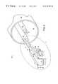
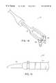
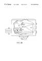
- FIG. 1 ais a perspective view of an electro-surgical device positioned within a resectoscope.
- FIG. 1 bis a perspective view of the electro-surgical device of FIG. 1 a.
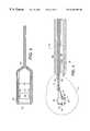
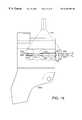
- FIG. 2is an enlarged perspective view of a-distal portion of the electro-surgical device of FIG. 1 a.
- FIG. 3is an enlarged top view of the distal portion of the electro-surgical device of FIG. 1 .
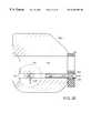
- FIG. 4is an enlarged cross-sectional side view of the distal portion of the electro-surgical device of FIG. 1 a.
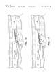
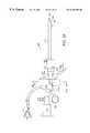
- FIGS. 5-9are cross-sectional side views of the distal portion of the electro-surgical device of FIG. 1 a in use within a urethra.
- FIGS. 10 and 11are cross-sectional side views illustrating structure and use of another embodiment of an electro-surgical device.
- FIG. 12is a side view of another embodiment of a resectoscope.
- FIG. 13is an exploded, side view of the resectoscope of FIG. 12 .
- FIG. 14is an enlarged perspective view of a distal portion of an electro-surgical device used in conjunction with the resectoscope of FIG. 12 .
- FIG. 15is an enlarged side view of a proximal portion of the electro-surgical device used lo in conjunction with the resectoscope of FIG. 12 .
- FIG. 16is an enlarged partially cross-sectional view of a portion of the handle of the resectoscope of FIG. 12 and a bipolar power connector adaptor.
- FIG. 17is a perspective view of another bipolar power connector adaptor that can be used in conjunction with the resectoscope of FIG. 12 .
- FIG. 18is an enlarged side view of a portion of the handle of the resectoscope of FIG. 12 in combination with the bipolar power connector adaptor of FIG. 17 .
- FIG. 19is a perspective view of a power connector adaptor for use in conjunction with another type of resectoscope.
- FIG. 20is an enlarged side view, shown in partial cross-section, of the power connector adaptor of FIG. 18 and a portion of the handle of a resectoscope.
- FIGS. 21 a - 21 care cross-sectional side views of the electro-surgical device of FIG. 12 in use within a urethra.
- FIG. 22is a side view of another electro-surgical device that can be used in conjunction with the resectoscope of FIG. 12 .
- FIG. 23is a side view of another electro-surgical device in a retracted position within a distal portion of a resectoscope.
- FIG. 24is a side view of the electro-surgical device of FIG. 23 in an extended position within the distal portion of the resectoscope.
- FIG. 25is a cross-sectional view of the electro-surgical device of FIG. 23 within the distal portion of the resectoscope.
- FIG. 26is a side view of another electro-surgical device in an extended position within the distal end of a resectoscope.
- FIG. 27 ais a perspective view of an electro-surgical device having a loop electrode.
- FIG. 27 bis an enlarged perspective view of a distal portion of the electro-surgical device of FIG. 27 a.
- FIG. 28is a cross-sectional view of a dual ion beam deposition chamber for depositing an insulative coating on an electrode.
- FIG. 29 ais a perspective view of another electro-surgical device having a loop electrode.
- FIG. 29 bis an enlarged perspective view of a distal portion of the electro-surgical device of FIG. 29 a.
- FIG. 30 ais a perspective view of an electro-surgical device having a cylindrical roller electrode.
- FIG. 30 bis a perspective view of an electro-surgical device having a spherical roller electrode.
- FIG. 31 ais a perspective view of another electro-surgical device having a loop electrode.
- FIG. 31 bis an enlarged perspective view from a proximal side of a distal portion of the electro-surgical device of FIG. 31 a.
- FIG. 32is a side view illustrating selective resection and cauterization of prostate tissue using the electro-surgical device of the present invention.
- FIG. 33 ais a side view of a biopsy forcep—, and —FIG. 33 b is an enlarged perspective view of a distal end of the biopsy forcep of FIG. 33 a.
- a transurethral resection assembly 10including a resectoscope 28 and a bipolar electro-surgical device 11 having a loop-form resecting electrode 12 and a coagulating electrode 14 .
- the larger surface area of coagulating electrode 14diffuses current to coagulate tissue over a large region while the smaller surface area of resecting electrode 12 concentrates current to resect immediately adjacent tissue. Since the coagulating electrode 14 is positioned ahead of the cutting electrode 12 along a line of resection 24 , tissue is coagulated just prior to resection.
- Coagulating electrode 14pivots (arrow 23 ) with respect to resecting electrode 12 through cantilever joint region 15 which controls the depth of resection and coagulation.
- the width W 2 of mounting fork 46 of coagulating electrode 14 and the width W 1 of mounting fork 48 of resecting electrode 12are substantially similar.
- mounting fork 48engages mounting fork 46 to limit the maximum depth of resection to avoid resection of tissue beyond the coagulation zone, as will be described in more detail below.
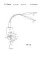
- Resecting electrode 12 and coagulating electrode 14are connected by wire leads that extend through electrical insulator jackets 16 , 18 , to a power source 21 (RF generator).
- the insulated leadsextend in close proximity through metal jacket 20 and are axially fixed relative to each other and jacket 20 by epoxy fill 17 .
- Metal jacket 20terminates proximally in articulation ring 22 a as shown in FIGS. 1 a and 1 b .
- Ring 22 b shown in FIG. 1 ais connected to resectoscope 28 .
- Rings 22 a and 22 bare electrically insulated from the electrodes 12 , 14 and enable a physician to move metal jacket 20 and, hence, the electrodes 12 , 14 within lumenal space 26 of resectoscope 28 in an axial direction along the resecting path 24 .
- the resectoscope 28also includes a telescope 30 that images and illuminates resecting path 24 .
- Telescope 30is attached to metal jacket 20 through clip 32 .
- separate lumens, one for metal jacket 20 and one for telescope 30are provided within resectoscope 28 .
- lumenal space 26is used to irrigate and displace fluid, such as urine in the urethra, in the area of resection.
- lumenal space 26is filled with a non-osmotic, non-electrolytic, high impedance fluid such as glycine (not shown).
- the non-osmotic nature of glycinereduces damaging cellular fluid absorption, and the non-electrolytic and high impedance nature of glycine insures that the current passed between the electrodes 12 , 14 is focused in the tissue between the two electrodes 12 , 14 .
- distilled wateri.e., deionized water
- distilled wateris non-electrolytic.
- distilled wateris osmotic.
- the substantially bloodless nature of the proceduresignificantly reduces the amount of fluid absorbed by the patient. Hence, the osmotic nature of distilled water does not typically pose a danger.
- resecting electrode 12is tungsten and coagulating electrode 14 is a silver/copper alloy
- the lead wires (not shown) within insulating jackets 16 , 18 , respectively,may be made of many materials, including brass, a copper alloy, or a silver alloy.
- Resecting electrode 12has a loopwire diameter d 1 of 0.012 inches as shown in FIG. 4, a length L 1 of 0.30 inches and a height H of 0.325 inches as shown in FIG. 2 .
- Coagulating electrode 14is a cylindrical roller with a diameter d 2 of about 0.125 to 0.187 inches as shown in FIG. 4 and a length L 2 of between 0.187-0.25 inches as shown in FIG. 2 . Electrodes 12 and 14 are separated by a distance d 3 of approximately 0.187 inches as shown in FIG. 4 .
- Pivoting action of the electrodes 12 , 14can be facilitated by making the mounting fork 48 of resecting electrode 12 stiffer than the mounting fork of coagulating electrode 14 , for example, by using a stiffer wire within insulating jacket 18 .
- Metal jacket 20is made of stainless steel and has an outer diameter of about 0.068 inches, a wall thickness of about 0.005 inches, and an axial length of about 8.0 inches.
- the power sourceis a surgical radio frequency (RF) generator, generating a continuous sine wave (i.e., cut waveform) and operating at a typical frequency of 1 MHz and at typical power levels of 100-300 Watts.
- RFradio frequency
- electro-surgical device 11will be described with regard to a transurethral resectioning procedure (TURP).
- the patientis prepared by inserting a resectoscope 28 to the region of treatment.
- the physicianwith a telescope and irrigation, inspects the region.
- the regionis then flushed with glycine or distilled water.
- the device 11is inserted into the patient's urethra 40 through the resectoscope 28 such that resecting electrode 12 and coagulating electrode 14 extend from resectoscope 28 .
- cantilever joint 15When first inserted, cantilever joint 15 is fully open such that coagulating electrode 14 rests on the surface of tissue to be resected and resecting electrode 12 is suspended a slight distance d 4 , approximately 0.040 inches, above the surface of the tissue to be resected.
- the separationis a safety factor since, if power is accidentally applied, current will not pass between the electrodes 12 , 14 in a glycine or distilled water environment until both electrodes 12 , 14 contact the tissue surface.
- both electrodes 12 , 14are in contact with the surface of the tissue to be cut, the physician applies power to the electrodes 12 , 14 through hand or foot controls (not shown). As discussed, both electrodes 12 and 14 must contact the tissue because the surrounding glycine or distilled water will not conduct current. Current 50 flows through the tissue between the two electrodes 12 , 14 .
- the projected surface area (i.e., shadow or tissue contact area) of coagulating electrode 14is about 2-5 times larger than the projected surface area of resecting electrode 12 . As a result, the current density at resecting electrode 12 is larger than the current density at coagulating electrode 14 .
- the larger surface area of coagulating electrode 14disburses current over a wide, deep area 29 and causes heating in the area sufficient only to coagulate the tissue (i.e., approximately 60-100° C.).
- the small surface area of resecting electrode 12concentrates the current density and causes heating in adjacent tissue sufficient to resect the tissue.
- the heatinginduces a vigorous vaporization in the area immediately adjacent the electrode surface.
- a plasma arcmay be generated in the area immediately adjacent the electrode 12 with temperatures of approximately 1000° C. and above. However, lower temperatures, without arcing, can be used for resection.
- the electrodes 12 , 14pivot bringing electrically insulated forks 46 , 48 in contact and causing resecting electrode 12 to resect the tissue to its maximum depth M 1 as shown in FIG. 7 .
- the length L 2 , shown in FIG. 3 of coagulating electrode 14can be less than the width W 1 of fork 48 , the contact of both insulated forks limits the maximum depth of resection. The maximum depth of resection is limited to prevent resection beyond the depth of coagulation.
- forks 46 , 48are in contact, approximately half of coagulating electrode 14 extends between the tines of fork 48 .
- the large surface area and low current density of coagulating electrode 14keeps coagulating electrode 14 from plunging into the tissue.
- Electrode 12 , 14Approximately 100-300 Watts of power applied to the electrodes 12 , 14 causes resecting electrode 12 to resect to a maximum depth M 1 of about 0.20 inches (0.5 cm) and coagulating electrode 14 to coagulate to a maximum depth M 2 of about 0.4 inches (1 cm). Coagulating 0.20 inches deeper than resection insures substantially bloodless resection.
- the physiciansqueezes articulation rings 22 a and 22 b together to pull the device 11 proximally.
- Coagulating electrode 14rolls, as indicated by arrow 50 , along resecting path 24 and resecting electrode 12 carves a chip 52 of tissue from urethra 40 .
- the resecting pathis from the bladder to the verumontanum in the prostate (approximately 1.5-10 inches).
- resectoscope 28When the physician has reached the end of resection path 24 such as, for example, the point where the physician wishes to stop resecting, he either stops applying upward pressure to resectoscope 28 allowing urethra 40 to cause resectoscope 28 to move in a downward direction, indicated by arrow 54 , or directly applies a downward force to move the resectoscope 28 in the downward direction.
- coagulating electrode 14travels ahead of resecting electrode 12 along the resecting path 24 , a small portion of coagulated tissue 58 remains in place, that is, the tissue is not resected.
- the resected chipsare normally kept in the patient's bladder, and once the resection is completed, the patient's bladder is evacuated to ensure removal all of the resected chips.
- another transurethral resection assembly 100includes an resectoscope, manufactured by Circon ACMI, 102 and a bipolar electro-surgical device 104 having two closely spaced, substantially similar loop-form electrodes 106 , 108 .
- the thickness T 1approximately 0.027′′, of loop electrode 106 is slightly smaller than the thickness T 2 , approximately 0.030′′, of loop electrode 108 .
- loop electrode 106is the hot or cutting electrode while loop electrode 108 is the cold or return electrode.
- Loop electrode 106can be a wedge-shaped electrode of the type described in Hahnen, U.S. Pat. No. 5,569,244, the entire disclosure of which is hereby incorporated herein by reference.
- loop electrode 106concentrates the current density and causes heating in adjacent tissue sufficient to resect the tissue.
- the current 107 passing between the electrodes 106 , 108is dispersed over a region of tissue in the area of the incision and causes heating in the region sufficient only to coagulate the tissue in the region.
- excessive powerapproximately 125-300 Watts
- the tissue in the area of the incisionmay be coagulated to a depth sufficient, to minimize or eliminate bleeding.
- ElectrodesSpacing two substantially similar loop electrodes a small distance d 5 , e.g., 0.027′′, apart provides a low impedance path between the loop electrodes and insures that the current passing between the loop electrodes is confined to a short path. Confining the current path permits safe high power, e.g., 125-300 Watts, electro-surgery. Additionally, the electrodes are capable of resecting tissue in a conductive liquid environment, e.g., saline, because the current is focused in the tissue between the electrodes and is not disbursed through the conductive liquid.
- a conductive liquid environmente.g., saline
- tissue absorptionmay still occur.
- a tumoris resected from the uterus wall.
- the uterusPrior to tissue resectioning, the uterus is pressure distended with fluid which significantly increases the likelihood of excessive fluid absorption.
- Excessive absorption of non-ionic fluids such as glycinecan lead to life-threatening electrolyte imbalance.
- Resecting tissue in an ionic liquid environment such as salinereduces the risk of electrolyte imbalance.
- loop electrodes 106 , 108are connected by wire leads that extend through electrical insulator jackets 110 , 112 to platinum electrical contact ring 114 and brass or bronze electrical contact pin 1 16 , respectively, which are mounted on the nylon shaft of bipolar electro-surgical device 104 .
- Pin 116includes a slot 220 that can be grasped by a knife edge lock in handle portion 126 a , as described below.
- the insulated leadsare axially fixed in parallel relative to each other.
- Bipolar electro-surgical device 104is inserted into resectoscope 102 through a distal end 123 of a metal jacket 124 in resectoscope 102 .
- a power connector 118electrically couples ring 114 and pin 116 with banana plugs 120 , 122 , respectively. During operation, the banana plugs 120 , 122 are connected to an RF generator (not shown).
- power connect 118is mounted on handle portion 126 a of the resectoscope.
- Handle portion 126 aincludes an internal knife-edge lock (not shown) that grasps bipolar electro-surgical device 104 once it has been inserted into aperture 125 of handle portion 126 a .
- a push-button release mechanism 133operates through an aperture 135 in handle portion 126 a to release bipolar electro-surgical device 104 from the knife edge lock so that it can be removed from handle portion 126 a.
- FIGS. 17 and 18illustrate one example of power connector 118 (note that the power connector shown in FIGS. 17 and 18 has a slightly different shape from the power connector shown in FIGS. 12, 13 , 16 , and 21 a - 21 c ).
- Power connector 118(shown in dashed lines in FIG. 18) is an adaptor power connector that is attachable to an ACMI resectoscope, which is designed for use with a monopolar electro-surgical device, to allow a physician to perform bipolar electro-surgery.
- the adaptor power connector 118may be an insert molded part.
- Arm 210 of power connector adaptor 118fits into a hole 218 in handle portion 126 a of the resectoscope. As shown, hole 218 is designed to permit an electrical connection to be made to the proximal tip of a monopolar electro-surgical device.
- Arm 206 of power connector adaptor 118fits immediately adjacent to the distal edge of handle portion 126 a.
- Pin 116 of bipolar electro-surgical device 104is inserted through hole 204 in arm 206 of power connector adaptor 118 , into an aperture 125 in handle portion 126 a of resectoscope 102 , and through hole 208 in arm 210 of power connector adaptor 118 .
- Handle portion 126 a of the resectoscopeincludes a knife edge lock 129 for grasping a slot in pin 116 .
- push-button release mechanism 133 in handle portion 126 areleases pin 116 from knife edge lock 129 so that bipolar electro-surgical device 104 can be removed from handle portion 126 a .
- Arm 210 of power connector adaptor 118includes a leaf spring connector 214 for grasping bullet tip 216 of pin 116 and electrically connecting to pin 116
- arm 206 of power connector adaptor 118includes a leaf spring connector 131 for grasping ring 114 and electrically connecting to ring 114 .
- An O-ring or a silicone membrane, such as, for example, a diaphragm or septum 200is placed at the opening 202 of hole 204 in power connector adaptor 118 to prevent liquid from entering the power connector adaptor 118 and handle portion 126 a and forming a conductive path between pin 116 and ring 114 .
- Pin 116is passed through the O-ring, diaphragm, or septum when the bipolar electro-surgical device is inserted within the power connector adaptor.
- bipolar electro-surgical device 104is removed from the resectoscope 102 using the push-button release and may be thrown away or cleaned. Prior to the next procedure, a physician may insert a new or cleaned electro-surgical device 104 within the resectoscope 102 .
- another power connector adaptor 118is configured for use in conjunction with a Storz resectoscope rather than an ACMI resectoscope.
- Handle portion 126 a of the Storz resectoscopeincludes a built-in mechanism (not shown) for electrically connecting to pin 116 of bipolar electro-surgical device 104
- power connector adaptor 118includes a leaf spring connector 131 for grasping ring 114 and electrically connecting to ring 114 .
- Pin 116is inserted through 204 in arm 206 of power connector adaptor 118 and intake aperture 125 in handle portion 126 a of resectoscope 102 .
- Handle portion 126 a of the resectoscopeincludes a push-button release mechanism 133 that operates through an aperture in handle portion 126 a to release pin 116 from knife edge lock 129 .
- An O-ring or a silicone membrane (i.e., diaphragm or septum) 200is placed at the opening 202 of hole 204 in power connector adaptor 118 to prevent liquid from entering the power connector adaptor and handle portion 126 a and forming a conductive path between pin 116 and ring 114 .
- the patientis prepared by inserting a bullet-nosed obturator (not shown) within a sheath 101 (FIG. 13) to the region of treatment.
- the obturatoris then removed from the sheath while leaving the sheath within the patient, and a resectoscope 102 and bipolar electro-surgical device 104 assembly is then inserted into the sheath 101 .
- the assemblyincludes a telescope 160 that is inserted through rail 134 and a metal jacket 162 (FIG. 13) of resectoscope 102 .
- With telescope 160 and irrigationthe physician inspects the region. The region is then flushed with saline.
- Resectoscope 102includes a two-piece handle having a proximal thumb piece 126 a and a distal finger piece 126 b .
- Power connector adaptor 118is attached to thumb piece 126 a .
- a physicianinserts his thumb through ring 128 in thumb piece 126 a and lays his fingers across indentations 130 a , 130 b , 130 c in finger piece 126 b and squeezes to slide (arrow 132 , FIG. 21 a ) the thumb piece along rails 134 , 136 against a force (arrow 138 ) provided by a spring 140 .
- the physicianapplies power to the loop electrodes 106 , 108 by turning on the RF generator and applies an upward pressure to the external end of resectoscope 102 , as indicated by arrow 147 , to bring the electrodes 106 , 108 in contact with tissue 155 .
- the physicianthen slowly releases his grip on the two-piece handle to allow the thumb piece to move away from (arrow 148 , FIG. 21 c ) the finger piece 126 b and the electrodes 106 , 108 to move back toward (arrow 150 ) the distal end of the sheath 101 .
- Electrodes 106 , 108are moved back toward the sheath 101 , cutting electrode 106 resects a chip 152 of tissue from a resecting path 154 within the patient's urethra 156 , and current 154 passing between the electrodes 106 , 108 coagulates tissue in the area 157 of the incision.
- the electrodes 106 , 108are pulled back into the sheath and chip 152 is cut off against a lower portion 158 of the distal end of the sheath.
- the physicianthen either stops applying upward pressure to resectoscope 102 allowing urethra 156 to cause the resectoscope 102 to move in a downward direction, indicated by arrow 159 , or directly applies a downward force to move the resectoscope 102 in the downward direction.
- the length L 2 of coagulating electrode 14can be cut with grooves (not shown) to increase the traction coagulating electrode 14 has with the tissue surface.
- the surface of coagulating electrode 14can be polished to prevent debris from sticking to coagulating electrode 14 .
- a sled electrodei.e., does not roll, not shown
- Coagulating electrode 14is preferred, however, because as coagulating electrode 14 rolls (i.e., turns in direction 50 ) it prevents the build up of debris along resecting path 24 .
- a resilient coil wirewith substantial “give” and with the same surface area could be used.
- a fluid flow directly over the electrodesmay be provided to wash away char that could interfere with current flow.
- the flowcould be provided by, for example, a small tube running through metal jacket 20 that terminates in a nozzle-form directed onto the electrode surfaces.
- the electrode and electrode leadcould be hollow allowing fluid to flow and the working surface perforated such that fluid weeps from the electrode to wash away char.
- the fluidmay be saline or another conductive fluid that does not inhibit current flow. Washing fluid flow can be initiated and terminated by a foot pedal, which may be the same foot pedal that turns on power.
- electrodes 12 and 14can be configured to move in an axial direction, that is, along resection path 24 independent of each other. This axial action can be achieved by passing the insulated leads to the resecting and coagulation electrodes 12 , 14 through separate lumens within sheath 20 .
- the physicianuses a mechanism to independently push coagulating electrode 14 back along resecting path 24 in an axial direction, indicated by arrow 60 , until coagulating electrode 14 is on an opposite side of resecting electrode 12 .
- coagulated tissue region 58is removed as part of chip 52 .
- the width W 2 (FIG. 2) of coagulating electrode 14 fork 46is much smaller than the width W 1 of resecting electrode 12 fork 48 . Additionally, to prevent the two electrodes 12 , 14 from coming in contact with each other, the length L 2 of coagulating electrode 14 is made less than the length L 1 of resecting electrode 12 .
- Allowing electrodes 12 and 14 to move in an axial direction independent of each othercan also be used to change the direction of resection.
- Urging coagulating electrode 14 to an opposite side of resecting electrode 12allows for coagulation and resection along a resecting path in a direction opposite to resecting path 24 . Because a physician normally carves out several chips out of the urethra in transurethral procedure, by changing the direction of the resecting path, the physician carves a chip out with each push and then with each pull of the device.
- the electrodes 12 , 14may also include a flushing apparatus to remove char.
- a tube 70extending from outside the device, terminates in a nozzle 72 that directs a flow of saline onto the roller.
- the resecting electrodeis a hollow-form with perforations 74 through which saline can be delivered to the working surface.
- Coupling and pivoting mechanismsother than the fork 46 , 48 arrangement, can be employed.
- the maximum depth of resectionmay not be limited by a stop engagement.
- the resecting electrode 12can be constructed such that the coagulation electrode 14 can pass beyond the mounting for the resecting electrode 12 . If the width of the fork of the coagulating electrode 14 is less than the width between the two loop halves of the resecting electrode 12 , the depth of resection is not limited.
- the physiciancan manually control the maximum depth of resection. Coagulation may be carried out just after resection, by reversing the orientation of the electrodes.
- the electro-surgical devicescan be constructed for use in various procedures, including endoscopic, laparoscopic (i.e., the electrode configuration extends through a trocar), and cystoscopic procedures.
- the devicecan have a flexible shaft for delivery deep into the body.
- the devicescan be configured for removal or debuiking of tumors in, e.g., the esophagus, cervix, or uterus (myomectomy), or for removal of liver lobe sections or removal of any protruding vascular tissue.
- the devicesmay also be configured to resect the lining of the uterus (endometrioma) or for use in transurethral resectioning of the bladder (TURB).
- the devicescan be constructed to carry multiple different resecting and/or coagulating electrodes among which power can be switched to vary the depth or width of treatment.
- the devicemay carry two resecting loops arranged and of different size to allow cutting to different maximum depths.
- Differently shaped coagulating electrodescan be carried to vary the coagulation pattern.
- the different electrodescan be arranged in parallel about or in series along the device axis.
- the power applied to the devicecan be varied with device construction and purpose (tissue type). Small scale devices, e.g., for use in the brain, may use lower power settings, e.g., 10 Watts.
- the arrangementcan be adapted for a hand-held device for use in open surgery.
- the resecting electrodecan be replaced with a different shaped small surface area resecting electrode
- the coagulating electrodecan be replaced with a different shaped larger surface area coagulating electrode.
- the device 104includes a loop electrode 106 but instead of providing a coagulating electrode (electrode 108 in FIG. 13 ), insulator jacket 112 is constructed to allow a steady stream of saline solution to be injected into the area to be coagulated. Current 107 passes between the electrode 106 and the saline stream. Insulator jacket 112 is constructed so as to maintain the saline solution in electrical contact with ring 114 or pin 116 at the proximal end of the bipolar electro-surgical device 104 .
- the steady stream of saline solutionfunctions as the equivalent of a thin, small diameter wire and coagulates tissue in a manner similar to, and with the same effect as, the embodiment of FIG. 13 .
- the embodiment of FIG. 22has the advantage that the initial impedance across the output leads of the RF generator can be higher than the initial impedance in the embodiment of FIG. 13 . This is important because certain RF generators are constructed, for safety reasons, to assume that if the initial impedance across the output leads is relatively low, a short circuit might be present. Under such conditions, the output current starts out low and then builds up as the RF generator learns that there is in fact no short circuit. The embodiment of FIG. 22, in contrast can avoid this current build-up time.
- FIGS. 23-25there is shown another bipolar electro-surgical device, having wedge-like resecting electrode 222 and loop return electrode 224 positioned at the ends of insulated wires 228 and 230 .
- the bipolar electro-surgical deviceis positioned within an electrically conductive environment such as a saline field 232 that is injected through resectoscope sheath 226 .
- a saline field 232that is injected through resectoscope sheath 226 .
- resectoscope sheath 226If the resectoscope sheath 226 is conductive, current passes from resecting electrode 222 through the tissue to resectoscope sheath 226 , and then from the resectoscope sheath 226 through saline 232 to return electrode 224 .
- An alternative embodimentis shown in FIG. 26, in which resecting electrode 222 is a wedge-like electrode as in FIGS. 23-25 but return electrode 224 is an exposed wire rather than a loop.
- the present inventionfurther contemplates the use of monopolar and bipolar electro-surgical devices for performing tissue resection.
- a monopolar electro-surgical deviceuses a single resecting electrode along with a surface return electrode.
- the monopolar electro-surgical deviceperforms both resection and coagulation.
- poweris applied to the monopolar resecting electrode, current density is concentrated at the tip of the resecting electrode, and a plasma field is generated as the electrode contacts the tissue. Generation of the plasma field causes heating of the tissue sufficient to resect the tissue.
- the electro-surgical devicescan be efficiently used with liquid mediums such as water, saline, glycine, or sorbitol.
- liquid mediumssuch as water, saline, glycine, or sorbitol.
- salinea fluid which is electrolytic, isotonic and non-osmotic can be used.
- salinea fluid which is electrolytic, isotonic and non-osmotic can be used.
- the use of saline with monopolar electro-surgical devicesposes several problems. Because saline is conductive, it is often difficult to generate a plasma field at the tip of the monopolar resecting electrode as current applied to the electrode quickly diffuses toward the saline and does not focus at the electrode tip.
- an RF generator in communication with the electrodewill sense that a short circuit is present at the electrode tip, because saline provides a low initial impedance across the output leads. Therefore, the output voltage starts low and then builds up as the RF generator learns that an impedance exists at the tip. The impedance builds up as the electrode is heated, causing the fluid in contact with the electrode to vaporize. The result is then an increase in the impedance of the system.
- the RF generatorresponds by increasing the amount of power delivered. This continues in the manufacturer's specified working impedance range. Above this range, the RF generator delivers decreasing amounts of power.
- the electro-surgical devices of the present inventionovercome these problems by being able to focus energy emission towards the tissue, preventing energy loss to the resected chips or the fluid delivered to the tissue site, while avoiding the need for higher power levels to achieve such an effect.
- the end effectis the increase in current density at the electrode.
- the resecting electrodes of the present inventionare capable of generating plasma fields in a tissue being irrigated with fluid, such as, for example, a non-osmotic fluid such as saline, glycine or sorbitol, without being embedded, within tissue.
- fluidsuch as, for example, a non-osmotic fluid such as saline, glycine or sorbitol
- lower power levelscan be used with the electro-surgical devices of the present invention in performing resection procedures, since diffusion of energy at the distal tip of the resecting electrode has been reduced.
- an electro-surgical deviceincludes an elongated body 300 , a pair of arms 302 extending from a distal end of the elongated body 300 , and a loop electrode 308 connecting the pair of arms 302 .
- the proximal end of the elongated body 300is adapted to be coupled to an energy source (not shown).
- Suitable conductive materials for the loop electrode 308can include, for example, stainless steel, tungsten, titanium, aluminum, brass, silver alloy, copper alloy, as well as other materials exhibiting conductive properties.
- the loop electrode 308comprises inner and outer flat surfaces 303 a , 303 b , and proximal and distal edges 301 a , 301 b .
- the proximal edge 301 acan be sharp to aid in performing resection.
- the loop electrode 308defines a pair of end sections 304 and a base section 306 .
- Each end section 304is coupled to an arm 302 and can comprise the conductive material having an insulative coating or sheath disposed thereon as further described.
- the base section 306lies between the end sections 304 and, in the present embodiment comprises the conductive material without an insulative coating.
- the base section 306is the first region to be contacting the target tissue.
- the electro-surgical devicecan further include a sheath or tubular member enclosing the elongated body 300 and for delivering fluid such as saline, glycine or sorbitol to a treatment path. In this embodiment, energy applied to the electrode 308 remains focused at the base section 306 when the probe is used along with an electrolytic fluid such as, for example, saline.
- the insulative coating disposed on the end sections 304comprises a material capable of remaining adhered to the conductive material forming the loop electrode 308 , upon application of a voltage of up to about 1000 volts to 2000 volts and upon generation of a plasma field near the electrode 308 .
- the pair of arms 302can be surrounded by an insulation sheath, or, in an alternative embodiment, the pair of arms 302 can have the same insulative coating covering the end sections 304 in addition to or instead of the insulation sheath. It is to be appreciated that finding the appropriate insulator for the coating is not a trivial matter as most insulators can disintegrate upon generation of plasma fields.
- a preferred insulator used in the present embodimentcan have superior electrical resistivity, dielectric strength, and hardness, in addition to having good adhesion to the conductive material forming the loop electrode 308 .
- the insulative coating disposed on the end sections 304can be a diamond-like carbon (DLC) coating sold under the trademark Diamonex® by Diamonex, a unit of Monsanto Company (Allentown, Pa.).
- DLCis an amorphous diamond material which resembles properties of a naturally occurring diamond.
- DLChas a hardness in the range from 1000 to 5000 kg/mm 2 , an electrical resistivity in the range from 10 4 to 10 12 ohms-cm, a dielectric constant of approximately 100 volts (rms) at mains frequency and good adhesion to a substrate.
- synthetic polycrystalline diamondcan be used as insulative coating on the end sections 304 .
- Polycrystalline diamondhas a thermal conductivity greater than 1000 W/m° K, an electrical resistivity of greater than 10 11 ohm-cm, a thermal expansion of about 2 ⁇ 10 ⁇ 6 /° C. between 25° C. and 200° C., a dielectric constant of about 5.7, a dielectric strength of about 300+V/ ⁇ m, and a shear strength of about 10 8 N/m 2 .
- DLCis vapor deposited onto the loop electrode 308 .
- the DLCcan be deposited by ion beam deposition, RF plasma deposition and by the process of polycrystalline growth.
- vapor depositionis a microfabrication technology well known to those skilled in the electronics fabrication art. Ion beam deposition technique is described in U.S. Pat. No. 5,508,368, which is incorporated herein by reference.
- DLCis deposited using a hot filament chemical vapor deposition technique.
- the DLC coating on the base section 306is then removed by etching or other removal processes, such as grinding and EDM (Electrical Discharge Machining) while the DLC coating on the end sections 304 remains.
- the base section 306is masked while DLC is vapor deposited on the loop electrode 308 , such that DLC is prevented from depositing on the base section 306 .
- plasmais generated by applying a mixture of hydrocarbon and argon gases 360 , 362 to each ion source 364 .
- Electrically charged grids 366are placed at one end of the ion source 364 .
- the grids 366extract and accelerate the hydrocarbon and argon ions 368 toward a substrate 370 to be coated.
- the substrate 370is maintained at a temperature between 20° C. and 50° C. as the substrate 370 is sufficiently remote from the plasma within the ion source 364 .
- the accelerated ions 368combine on the surface of the substrate 370 to produce an amorphous carbon coating. The process causes some of the ions to embed in the substrate 370 thereby providing excellent adhesion.
- the DLC coating placed on the end sections 304can have a thickness up to about 10 microns. It is to be appreciated that this thickness can vary depending on the intended application of the device. For example, in one embodiment, the film is evenly deposited and the thickness of the film can vary from about 6 microns to about 10 microns.
- the electro-surgical device 310includes an elongated body 312 , a pair of arms 314 extending from a distal end of the elongated body 312 , and an electrode 316 in communication with the pair of arms 314 .
- the electrode 316has a plurality of randomly dispersed conductive regions 318 .
- the conductive regions 318are created by a non-uniformly deposited insulative coating 320 on the electrode 316 .
- Such non-uniform depositionallows energy emission to preferentially breakthrough the thinner coated regions.
- the thickness of the filmcan be as small as 1 micron, for example and as large as, for example, about 10 microns.
- the thickness of the film in other embodiment'scan be greater than 10 microns or less than 1 micron.
- the conductive regions 318are dispersed, the conductive regions 318 are capable of transmitting a current of up to 2 Amps to tissue disposed near the conductive regions 318 in order to perform resection. It is to be appreciated that higher currents can be supplied depending on the intended application.
- the conductive regions 318can comprise a plurality of pin holes created by the process of vapor deposition of the insulative coating 320 on the electrode, described above.
- the electro-surgical devicecan further include a sheath for carrying the elongated body 312 and for delivering an electrolytic non-osmotic fluid such as saline, to a treatment path.
- energy applied to the electrode 316remains focused at the conductive regions 318 when used in conjunction with an electrolytic fluid.
- the electrode 316comprises a substantially U-shaped loop electrode.
- the insulative coatingmay be placed on other types of electrodes such as a cylindrical roller electrode or a spherical roller electrode, as shown in FIGS. 30 a and 30 b , respectively.
- the electro-surgical deviceincludes an elongated body 321 , a pair of arms 323 in communication with the distal end of the elongated body 321 , and a cylindrical roller electrode 322 connected to the pair of arms 323 .
- the arms 323can have an insulative sheath 324 or coating disposed thereon, and the roller electrode 322 can be completely or partially conductive.
- the roller electrode 322can be coated with a DLC or other coating having a certain resistance to cracking at high temperatures and high voltages.
- energyis focused in the middle of the roller electrode 325 b .
- the roller electrode 327can include an uneven deposition of insulative coating such as that shown in FIG. 30 b.
- an electro-surgical deviceincludes an elongated body 328 in communication with a pair of arms 326 at a distal end, and a spherical roller ball electrode 327 connecting the pair of arms 326 .
- the spherical rollerball electrode 327operates in a similar fashion as described in the embodiment of FIGS. 29 a and 29 b .
- the uneven deposition of a DLC or other coating 329 ballows energy to be focused at the conductive regions 329 a of the roller ball electrode 327 .
- the embodiments described in FIG. 30 a and FIG. 30 bcan further include a sheath enclosing the elongated body 321 , 328 for delivering fluid to the treatment site.
- the electro-surgical device 330includes an elongated body 332 , a pair of arms 334 extending from a distal end of the elongated body 332 , and an electrode 340 in communication with the pair of arms 334 .
- the pair of arms 334can have an insulative sheath or coating, as described above.
- the electrode 340has a first region 336 covered with an insulative coating and a second region 338 covered with graphite. By coating the second region 338 with graphite, the second region 338 is masked while the first region is subsequently coated with the insulative coating, such as DLC or other insulative material.
- Graphiteis placed on the second region 338 by dipping, brushing, and spraying.
- the graphite coveringdoes not allow the insulator to bond to it, and thus leaves the second region 338 free of insulative coating.
- the graphite that remains on the second region 338thereafter disintegrates upon the application of a voltage of greater than 100 volts (peak to peak) at RF frequency to the electrode 340 and exposes a conductive region underneath. Thus the conductive region is exposed and energy is focused at the conductive region during a resection procedure.
- the electrode 340is a loop electrode having a sharp proximal edge 341 used in resection.
- the second region 338comprises an area immediately adjacent the sharp proximal edge 341
- the first region 336comprises the remainder of the electrode 340 .
- the electro-surgical device 330can further include a sheath for carrying the elongated body 332 and for delivering a non-osmotic fluid such as saline, glycine or sorbitol to a treatment path.
- energy applied to the electrode 340remains focused at the second region 318 when used in conjunction with a fluid.
- a resectoscope assembly 343includes a resectoscope 342 defining a channel (not shown) and an electro-surgical device 344 insertable through the channel.
- the electro-surgical device 344may be of any embodiment described above with reference to FIGS. 27 a to 30 b .
- a return electrode 348is positioned on a surface of the body 350 and the resectoscope assembly 342 is inserted inside the urethra 352 .
- the electro-surgical device 344is inserted through the channel of the resectoscope 342 and positioned along a treatment path near prostate tissue 354 to be resected.
- the resectoscope 342includes a telescope 356 at a distal end, such that the electro-surgical device 344 can be positioned under observation.
- the tissue to be resectedis flushed with a non-osmotic fluid introduced through a luer port 358 for injecting fluid.
- the non-osmotic fluidcan be a non-osmotic, electrolytic fluid such as saline.
- the non-osmotic fluidcan be a non-osmotic, non-electrolytic fluid such as glycine or sorbitol.
- a voltage in the range from about 1000 volts to 2000 volts (peak to peak)is applied across the resecting electrode 346 and the return electrode 348 to generate a plasma field, without embedding the resecting electrode 346 inside the prostate tissue 354 .
- the resecting electrode 346is moved along the treatment path to resect and coagulate the prostate tissue 354 .
- the resectoscope assembly 343can be inserted deeper into the bladder 360 to resect bladder tissues.
- the resectoscope assembly 343can be inserted inside a female patient to resect a tumor from the walls of the uterus or to resect an endometrium lining.
- bipolar electrodes in addition to monopolar electrodescan be selectively coated with an insulative coating for limiting current distribution according to the invention.
- biopsy forcepscan be selectively coated with an insulative coating to prevent the biopsy sample from being damaged.
- the inner surfaces of the biopsy forcep that comes in contact with the removed biopsy samplecan be coated with the insulative coating, while the outer surfaces of the forceps used to remove the sample can remain conductive.
Landscapes
- Health & Medical Sciences (AREA)
- Surgery (AREA)
- Engineering & Computer Science (AREA)
- Life Sciences & Earth Sciences (AREA)
- Biomedical Technology (AREA)
- Otolaryngology (AREA)
- Nuclear Medicine, Radiotherapy & Molecular Imaging (AREA)
- Plasma & Fusion (AREA)
- Physics & Mathematics (AREA)
- Heart & Thoracic Surgery (AREA)
- Medical Informatics (AREA)
- Molecular Biology (AREA)
- Animal Behavior & Ethology (AREA)
- General Health & Medical Sciences (AREA)
- Public Health (AREA)
- Veterinary Medicine (AREA)
- Surgical Instruments (AREA)
Abstract
Description
Claims (12)
Priority Applications (11)
| Application Number | Priority Date | Filing Date | Title |
|---|---|---|---|
| US08/940,665US6494881B1 (en) | 1997-09-30 | 1997-09-30 | Apparatus and method for electrode-surgical tissue removal having a selectively insulated electrode |
| PCT/US1998/020112WO1999016371A1 (en) | 1997-09-30 | 1998-09-25 | Apparatus for electro-surgical tissue removal |
| CA002304737ACA2304737C (en) | 1997-09-30 | 1998-09-25 | Apparatus for electro-surgical tissue removal |
| DE69834825TDE69834825T2 (en) | 1997-09-30 | 1998-09-25 | ELECTRO-SURGICAL DEVICE FOR TISSUE REMOVAL |
| JP2000513517AJP4108928B2 (en) | 1997-09-30 | 1998-09-25 | Device for electrosurgical tissue removal |
| EP98949513AEP1018960B1 (en) | 1997-09-30 | 1998-09-25 | Apparatus for electro-surgical tissue removal |
| AU95820/98AAU740103B2 (en) | 1997-09-30 | 1998-09-25 | Apparatus for electro-surgical tissue removal |
| IL13535498AIL135354A0 (en) | 1997-09-30 | 1998-09-25 | Apparatus for electro-surgical tissue removal |
| IL135354AIL135354A (en) | 1997-09-30 | 2000-03-29 | Apparatus for electro-surgical tissue removal |
| US10/292,162US20030130653A1 (en) | 1997-09-30 | 2002-11-12 | Electrosurgical tissue removal with a selectively insulated electrode |
| US12/027,859US20080221567A1 (en) | 1997-09-30 | 2008-02-07 | Electrosurgical tissue removal with a selectively insulated electrode |
Applications Claiming Priority (1)
| Application Number | Priority Date | Filing Date | Title |
|---|---|---|---|
| US08/940,665US6494881B1 (en) | 1997-09-30 | 1997-09-30 | Apparatus and method for electrode-surgical tissue removal having a selectively insulated electrode |
Related Child Applications (1)
| Application Number | Title | Priority Date | Filing Date |
|---|---|---|---|
| US35933599AContinuation-In-Part | 1997-09-30 | 1999-07-21 |
Publications (1)
| Publication Number | Publication Date |
|---|---|
| US6494881B1true US6494881B1 (en) | 2002-12-17 |
Family
ID=25475225
Family Applications (1)
| Application Number | Title | Priority Date | Filing Date |
|---|---|---|---|
| US08/940,665Expired - Fee RelatedUS6494881B1 (en) | 1997-09-30 | 1997-09-30 | Apparatus and method for electrode-surgical tissue removal having a selectively insulated electrode |
Country Status (8)
| Country | Link |
|---|---|
| US (1) | US6494881B1 (en) |
| EP (1) | EP1018960B1 (en) |
| JP (1) | JP4108928B2 (en) |
| AU (1) | AU740103B2 (en) |
| CA (1) | CA2304737C (en) |
| DE (1) | DE69834825T2 (en) |
| IL (2) | IL135354A0 (en) |
| WO (1) | WO1999016371A1 (en) |
Cited By (153)
| Publication number | Priority date | Publication date | Assignee | Title |
|---|---|---|---|---|
| US20020072688A1 (en)* | 1998-03-03 | 2002-06-13 | Senorx, Inc. | Breast biopsy system and methods |
| US20020111564A1 (en)* | 1998-04-08 | 2002-08-15 | Senorx, Inc. | Tissue acquisition system and method of use |
| US20030176812A1 (en)* | 1998-03-03 | 2003-09-18 | Senorx, Inc. | Tissue specimen encapsulation device and method thereof |
| US20040039249A1 (en)* | 2002-04-12 | 2004-02-26 | Olympus Optical Co., Ltd. | Incising device for use with an endoscope |
| US20040092986A1 (en)* | 2000-06-15 | 2004-05-13 | Issac-Jacques Kadoch | Cutting tool for tissue surgical resection |
| US20040167428A1 (en)* | 2003-02-24 | 2004-08-26 | Senorx, Inc. | Biopsy device with inner cutting member |
| US20040215187A1 (en)* | 1998-03-03 | 2004-10-28 | Senorx, Inc. | Apparatus and method for accessing a body site |
| US20040254571A1 (en)* | 2003-01-31 | 2004-12-16 | Kobi Iki | Cartilage treatment probe |
| US20050070895A1 (en)* | 2003-09-30 | 2005-03-31 | Thomas Ryan | Electrosurgical instrument and method for transecting an organ |
| US20050234442A1 (en)* | 1999-09-01 | 2005-10-20 | Michael Spears | Electrosurgical cutting and cauterizing device |
| US7118528B1 (en)* | 2004-03-16 | 2006-10-10 | Gregory Piskun | Hemorrhoids treatment method and associated instrument assembly including anoscope and cofunctioning tissue occlusion device |
| US7134381B2 (en) | 2003-08-21 | 2006-11-14 | Nissan Motor Co., Ltd. | Refrigerant compressor and friction control process therefor |
| US20060264706A1 (en)* | 2004-03-16 | 2006-11-23 | Gregory Piskun | Endoluminal treatment method and associated surgical assembly including tissue occlusion device |
| US7146956B2 (en) | 2003-08-08 | 2006-12-12 | Nissan Motor Co., Ltd. | Valve train for internal combustion engine |
| US20070034211A1 (en)* | 2003-06-17 | 2007-02-15 | Bernhard Hug | Electrosurgical instrument for an endoscopre or a catheter |
| US20070066976A1 (en)* | 2004-10-05 | 2007-03-22 | Olympus Corporation | High-frequency treatment apparatus |
| US20070093812A1 (en)* | 2004-10-05 | 2007-04-26 | Olympus Corporation | High-frequency treatment apparatus |
| US7228786B2 (en) | 2003-06-06 | 2007-06-12 | Nissan Motor Co., Ltd. | Engine piston-pin sliding structure |
| US20070156127A1 (en)* | 2005-12-29 | 2007-07-05 | Boston Scientific Scimed, Inc. | Foam electrode and method of use thereof during tissue resection |
| US7255083B2 (en) | 2002-10-16 | 2007-08-14 | Nissan Motor Co., Ltd. | Sliding structure for automotive engine |
| US20070203489A1 (en)* | 2003-04-28 | 2007-08-30 | Olympus Corporation | High-frequency current treatment tool |
| US7273655B2 (en) | 1999-04-09 | 2007-09-25 | Shojiro Miyake | Slidably movable member and method of producing same |
| US7282034B2 (en) | 1998-09-01 | 2007-10-16 | Senorx, Inc. | Tissue accessing and anchoring device and method |
| US7284525B2 (en) | 2003-08-13 | 2007-10-23 | Nissan Motor Co., Ltd. | Structure for connecting piston to crankshaft |
| WO2006108163A3 (en)* | 2005-04-06 | 2007-11-01 | Canady Technology Llc | Apc dual mode leep apparatus and method |
| US7318514B2 (en) | 2003-08-22 | 2008-01-15 | Nissan Motor Co., Ltd. | Low-friction sliding member in transmission, and transmission oil therefor |
| US7322749B2 (en) | 2002-11-06 | 2008-01-29 | Nissan Motor Co., Ltd. | Low-friction sliding mechanism |
| US7329228B2 (en) | 1998-03-03 | 2008-02-12 | Senorx, Inc. | Methods and apparatus for securing medical instruments to desired locations in a patient's body |
| US7357801B2 (en) | 1998-04-08 | 2008-04-15 | Senorx, Inc. | Tissue specimen isolating and damaging device and method |
| US7377902B2 (en) | 1998-04-08 | 2008-05-27 | Senorx, Inc. | Biopsy anchor device with cutter |
| US7406940B2 (en) | 2003-05-23 | 2008-08-05 | Nissan Motor Co., Ltd. | Piston for internal combustion engine |
| US7427162B2 (en) | 2003-05-27 | 2008-09-23 | Nissan Motor Co., Ltd. | Rolling element |
| US7458585B2 (en) | 2003-08-08 | 2008-12-02 | Nissan Motor Co., Ltd. | Sliding member and production process thereof |
| US7500472B2 (en) | 2003-04-15 | 2009-03-10 | Nissan Motor Co., Ltd. | Fuel injection valve |
| US7572236B2 (en) | 2005-08-05 | 2009-08-11 | Senorx, Inc. | Biopsy device with fluid delivery to tissue specimens |
| US7572200B2 (en) | 2003-08-13 | 2009-08-11 | Nissan Motor Co., Ltd. | Chain drive system |
| US7625347B2 (en) | 1998-03-03 | 2009-12-01 | Senorx, Inc. | Electrosurgical biopsy device and method |
| US20090306642A1 (en)* | 2008-06-10 | 2009-12-10 | Vankov Alexander B | Method for low temperature electrosugery and rf generator |
| US7641651B2 (en) | 2005-07-28 | 2010-01-05 | Aragon Surgical, Inc. | Devices and methods for mobilization of the uterus |
| US20100010485A1 (en)* | 2008-07-10 | 2010-01-14 | Hs West Investments, Llc | Electrosurgical instrument with an ablation mode and a coagulation mode |
| US7651467B2 (en) | 1998-04-08 | 2010-01-26 | Senorx, Inc | Dilation devices and methods for removing tissue specimens |
| US20100106153A1 (en)* | 2008-07-10 | 2010-04-29 | Hs West Investments, Llc | Electrosurgical instrument with an ablation mode and a coagulation mode |
| US7771821B2 (en) | 2003-08-21 | 2010-08-10 | Nissan Motor Co., Ltd. | Low-friction sliding member and low-friction sliding mechanism using same |
| US7794461B2 (en) | 2006-03-08 | 2010-09-14 | Aragon Surgical, Inc. | Method and apparatus for surgical electrocautery |
| US7797056B2 (en) | 2005-09-06 | 2010-09-14 | Nmt Medical, Inc. | Removable intracardiac RF device |
| US20100268224A1 (en)* | 2009-04-17 | 2010-10-21 | Trevor Landon | Bipolar electrosurgical tool with active and return electrodes shaped to foster diffuse current flow in the tissue adjacent the return electrode |
| US7857827B2 (en) | 2006-04-14 | 2010-12-28 | Ethicon Endo-Surgery, Inc. | Endoscopic device |
| US7862565B2 (en) | 2005-05-12 | 2011-01-04 | Aragon Surgical, Inc. | Method for tissue cauterization |
| US20110172491A1 (en)* | 2009-10-01 | 2011-07-14 | Macroplata, Inc. | Detachable balloon catheter |
| US7988690B2 (en) | 2004-01-30 | 2011-08-02 | W.L. Gore & Associates, Inc. | Welding systems useful for closure of cardiac openings |
| US7998167B2 (en) | 2006-04-14 | 2011-08-16 | Ethicon Endo-Surgery, Inc. | End effector and method of manufacture |
| US8066700B2 (en)* | 2003-01-31 | 2011-11-29 | Smith & Nephew, Inc. | Cartilage treatment probe |
| US8066689B2 (en) | 2007-07-11 | 2011-11-29 | Apollo Endosurgery, Inc. | Methods and systems for submucosal implantation of a device for diagnosis and treatment with a therapeutic agent |
| US20120004657A1 (en)* | 2010-06-30 | 2012-01-05 | Salient Surgical Technologies, Inc. | Electrosurgical Devices with Wire Electrode And Methods of Use Thereof |
| US8096205B2 (en) | 2003-07-31 | 2012-01-17 | Nissan Motor Co., Ltd. | Gear |
| US8128592B2 (en) | 2007-07-11 | 2012-03-06 | Apollo Endosurgery, Inc. | Methods and systems for performing submucosal medical procedures |
| US20120116378A1 (en)* | 2010-04-26 | 2012-05-10 | Minerva Surgical, Inc. | Endometrial ablation with a device that conforms to symmetric or asymmetric uterine cavities |
| US8206035B2 (en) | 2003-08-06 | 2012-06-26 | Nissan Motor Co., Ltd. | Low-friction sliding mechanism, low-friction agent composition and method of friction reduction |
| US8282573B2 (en) | 2003-02-24 | 2012-10-09 | Senorx, Inc. | Biopsy device with selectable tissue receiving aperture orientation and site illumination |
| US8313500B2 (en) | 2006-04-14 | 2012-11-20 | Ethicon Endo-Surgery, Inc. | Endoscopic device |
| US8317771B2 (en) | 2007-07-11 | 2012-11-27 | Apollo Endosurgery, Inc. | Methods and systems for performing submucosal medical procedures |
| US8317725B2 (en) | 2005-08-05 | 2012-11-27 | Senorx, Inc. | Biopsy device with fluid delivery to tissue specimens |
| US20120330098A1 (en)* | 2011-06-24 | 2012-12-27 | Richard Wolf Gmbh | Working insert for an endoscopic hollow shank instrument |
| US8343071B2 (en) | 2004-12-16 | 2013-01-01 | Senorx, Inc. | Biopsy device with aperture orientation and improved tip |
| US8419727B2 (en) | 2010-03-26 | 2013-04-16 | Aesculap Ag | Impedance mediated power delivery for electrosurgery |
| US8506479B2 (en) | 2009-12-16 | 2013-08-13 | Macroplata, Inc. | Substantially rigid and stable endoluminal surgical suite for treating a gastrointestinal lesion |
| US20130267951A1 (en)* | 2012-04-06 | 2013-10-10 | Tyco Healthcare Group Lp | Spindle Assembly With Mechanical Fuse for Surgical Instruments |
| US8574229B2 (en) | 2006-05-02 | 2013-11-05 | Aesculap Ag | Surgical tool |
| WO2013167693A1 (en)* | 2012-05-09 | 2013-11-14 | Inp Greifswald - Leibniz-Institut Für Plasmaforschung Und Technologie E. V. | Device for the plasma treatment of human, animal or plant surfaces, in particular of skin or mucous membrane areas |
| US8632458B2 (en) | 2011-10-26 | 2014-01-21 | Macroplata Inc. | Gentle hemorrhoid treatment offering a substantially painless healing |
| US8696662B2 (en) | 2005-05-12 | 2014-04-15 | Aesculap Ag | Electrocautery method and apparatus |
| US8728072B2 (en) | 2005-05-12 | 2014-05-20 | Aesculap Ag | Electrocautery method and apparatus |
| US20140188105A1 (en)* | 2010-06-30 | 2014-07-03 | Medtronic Advanced Energy Llc | Bipolar electrosurgical device |
| USD709613S1 (en)* | 2012-11-07 | 2014-07-22 | Karl Storz Gmbh & Co. Kg | Cutting electrode |
| USD712032S1 (en)* | 2012-11-07 | 2014-08-26 | Karl Storz Gmbh & Co. Kg | Cutting electrode |
| US8827992B2 (en) | 2010-03-26 | 2014-09-09 | Aesculap Ag | Impedance mediated control of power delivery for electrosurgery |
| US8870867B2 (en) | 2008-02-06 | 2014-10-28 | Aesculap Ag | Articulable electrosurgical instrument with a stabilizable articulation actuator |
| US8929988B2 (en) | 2007-07-11 | 2015-01-06 | Apollo Endosurgery, Inc. | Methods and systems for submucosal implantation of a device for diagnosis and treatment of a body |
| US8932211B2 (en) | 2012-06-22 | 2015-01-13 | Macroplata, Inc. | Floating, multi-lumen-catheter retractor system for a minimally-invasive, operative gastrointestinal treatment |
| US8968275B2 (en) | 2010-04-26 | 2015-03-03 | Covidien Lp | Apparatus and method for effecting at least one anatomical structure |
| US20150066018A1 (en)* | 2013-08-30 | 2015-03-05 | Karl Storz Gmbh & Co. Kg | Medical Instrument And Electrosurgical System |
| US8998897B2 (en) | 2011-08-19 | 2015-04-07 | Cook Medical Technologies Llc | Ablation cap |
| US9168092B2 (en) | 2011-02-17 | 2015-10-27 | Megadyne Medical Products, Inc. | Surgical instrument with protective sheath |
| US9173698B2 (en) | 2010-09-17 | 2015-11-03 | Aesculap Ag | Electrosurgical tissue sealing augmented with a seal-enhancing composition |
| US9186131B2 (en) | 2009-12-16 | 2015-11-17 | Macroplata, Inc. | Multi-lumen-catheter retractor system for a minimally-invasive, operative gastrointestinal treatment |
| US20150359585A1 (en)* | 2014-06-11 | 2015-12-17 | Tdm Surgitech, Inc. | Apparatus, systems, and methods for dissection and modification of tissues |
| US9259267B2 (en) | 2005-09-06 | 2016-02-16 | W.L. Gore & Associates, Inc. | Devices and methods for treating cardiac tissue |
| US9339327B2 (en) | 2011-06-28 | 2016-05-17 | Aesculap Ag | Electrosurgical tissue dissecting device |
| US9339323B2 (en) | 2005-05-12 | 2016-05-17 | Aesculap Ag | Electrocautery method and apparatus |
| US9408592B2 (en) | 2003-12-23 | 2016-08-09 | Senorx, Inc. | Biopsy device with aperture orientation and improved tip |
| US20160317213A1 (en)* | 2014-03-26 | 2016-11-03 | Olympus Winter & Ibe Gmbh | Urological instrument |
| RU2603296C2 (en)* | 2010-11-02 | 2016-11-27 | Ю.С. Пейтент Инновейшнс | System and method for electrosurgical conductive gas cutting for improving eschar, sealing vessels and tissues |
| US9526570B2 (en) | 2012-10-04 | 2016-12-27 | Cook Medical Technologies Llc | Tissue cutting cap |
| WO2017016761A1 (en) | 2015-07-27 | 2017-02-02 | Hochschule Für Angewandte Wissenschaft Und Kunst Hildesheim/Holzminden/Göttingen | Electrode arrangement and plasma-treatment apparatus for surface-treating a body |
| US9565998B2 (en) | 2009-12-16 | 2017-02-14 | Boston Scientific Scimed, Inc. | Multi-lumen-catheter retractor system for a minimally-invasive, operative gastrointestinal treatment |
| US20170189053A1 (en)* | 2015-12-31 | 2017-07-06 | Terumo Kabushiki Kaisha | Medical device and method |
| WO2017141192A1 (en)* | 2016-02-19 | 2017-08-24 | Medident Technologies Inc. | Tissue treatment with plasma arc stream |
| US20170273733A1 (en)* | 2016-03-26 | 2017-09-28 | Paul Joseph Weber | Apparatus, systems and methods for minimally invasive dissection of tissues |
| US20170333114A1 (en)* | 2016-05-23 | 2017-11-23 | Gyrus Medical Limited | Electrode assembly |
| US9827037B2 (en)* | 2011-04-11 | 2017-11-28 | Boston Scientific Scimed, Inc. | Tissue extraction devices and methods |
| GB2551117A (en)* | 2016-05-31 | 2017-12-13 | Creo Medical Ltd | Electrosurgical apparatus and method |
| US9848763B2 (en) | 2008-05-15 | 2017-12-26 | Apollo Endosurgery Us, Inc. | Access systems and methods of intra-abdominal surgery |
| US9872724B2 (en) | 2012-09-26 | 2018-01-23 | Aesculap Ag | Apparatus for tissue cutting and sealing |
| US9877769B2 (en)* | 2008-07-22 | 2018-01-30 | Covidien Lp | Electrosurgical devices, systems and methods of using the same |
| US9918778B2 (en) | 2006-05-02 | 2018-03-20 | Aesculap Ag | Laparoscopic radiofrequency surgical device |
| CN108186109A (en)* | 2018-02-02 | 2018-06-22 | 云南省肿瘤医院 | Trans- hook-shaped bladder tumor cutting electrode |
| US10201267B2 (en)* | 2016-05-24 | 2019-02-12 | Phoenix Spine Holdings, Inc. | Methods and apparatus for facilitating direct visualized rhizotomy |
| US10376382B2 (en) | 2016-11-16 | 2019-08-13 | Phoenix Spine Holdings, Inc. | Methods and apparatus for facilitating a posterior lumbar interbody fusion procedure |
| US10531869B2 (en) | 2009-12-16 | 2020-01-14 | Boston Scientific Scimed, Inc. | Tissue retractor for minimally invasive surgery |
| US10595711B2 (en) | 2009-12-16 | 2020-03-24 | Boston Scientific Scimed, Inc. | System for a minimally-invasive, operative gastrointestinal treatment |
| US10758116B2 (en) | 2009-12-16 | 2020-09-01 | Boston Scientific Scimed, Inc. | System for a minimally-invasive, operative gastrointestinal treatment |
| CN111629682A (en)* | 2018-01-10 | 2020-09-04 | 美敦力公司 | Directionally focused ablation device |
| DE102019107321A1 (en)* | 2019-03-21 | 2020-09-24 | Relyon Plasma Gmbh | Device for generating a plasma and method for plasma treatment of a surface |
| US10893899B2 (en) | 2016-03-26 | 2021-01-19 | Paul Weber | Apparatus and systems for minimally invasive dissection of tissues |
| US10966701B2 (en) | 2009-12-16 | 2021-04-06 | Boston Scientific Scimed, Inc. | Tissue retractor for minimally invasive surgery |
| US11071534B2 (en) | 2016-12-30 | 2021-07-27 | Boston Scientific Scimed, Inc. | System for a minimally-invasive treatment within a body lumen |
| US11076902B2 (en) | 2018-02-22 | 2021-08-03 | Phoenix Spine Holdings, Inc. | Locking screw assembly for facilitating direct lateral interbody fusion procedures |
| US20210236188A1 (en)* | 2020-02-05 | 2021-08-05 | Covidien Lp | Electrosurgical device for cutting tissue |
| CN113453605A (en)* | 2018-12-27 | 2021-09-28 | 奥林巴斯株式会社 | Electrode unit and endoscope system |
| CN113473930A (en)* | 2018-12-14 | 2021-10-01 | 奥林巴斯株式会社 | Electrode unit and endoscope system |
| CN113645916A (en)* | 2019-01-28 | 2021-11-12 | 奥林巴斯株式会社 | Electrode unit and endoscope system |
| USRE48850E1 (en) | 2009-12-16 | 2021-12-14 | Boston Scientific Scimed, Inc. | Multi-lumen-catheter retractor system for a minimally-invasive, operative gastrointestinal treatment |
| US11241560B2 (en) | 2017-03-18 | 2022-02-08 | Boston Scientific Scimed, Inc. | System for a minimally-invasive treatment within a body lumen |
| US20220280219A1 (en)* | 2019-07-23 | 2022-09-08 | Erbe Elektromedizin Gmbh | Electrode arrangement |
| US11510730B2 (en) | 2016-03-26 | 2022-11-29 | Paul Joseph Weber | Apparatus and methods for minimally invasive dissection and modification of tissues |
| US20220409263A1 (en)* | 2021-06-25 | 2022-12-29 | Medtronic Advanced Energy Llc | Plasma coring tool with endpoint detection |
| US20230022232A1 (en)* | 2019-12-23 | 2023-01-26 | Medtecton Gmbh | Device for the Enucleation of Intracorporeal Tissue Regions |
| US11596467B2 (en) | 2020-02-04 | 2023-03-07 | Covidien Lp | Articulating tip for bipolar pencil |
| US20230081374A1 (en)* | 2021-08-25 | 2023-03-16 | Eximis Surgical Inc. | Segmentation instrument and controller |
| US20230096656A1 (en)* | 2021-09-29 | 2023-03-30 | Kester Julian Batchelor | Resistive coating device and method |
| US11648046B2 (en) | 2020-04-29 | 2023-05-16 | Covidien Lp | Electrosurgical instrument for cutting tissue |
| US11684413B2 (en) | 2020-05-22 | 2023-06-27 | Covidien Lp | Smoke mitigation assembly for bipolar pencil |
| US11696798B2 (en)* | 2017-06-15 | 2023-07-11 | Conmed Corporation | Coated electrosurgical vessel sealer electrodes |
| US11712285B2 (en) | 2020-04-23 | 2023-08-01 | Covidien Lp | Dual-threaded tensioning mechanism for bipolar pencil |
| US11779394B2 (en) | 2020-01-30 | 2023-10-10 | Covidien Lp | Single-sided low profile end effector for bipolar pencil |
| US11826091B2 (en)* | 2016-08-16 | 2023-11-28 | Xcellanxe Medical Technologies Pvt Ltd | Bipolar electrosurgical cutting and coagulation instrument |
| US11832789B2 (en) | 2019-12-13 | 2023-12-05 | Boston Scientific Scimed, Inc. | Devices, systems, and methods for minimally invasive surgery in a body lumen |
| US11864817B2 (en) | 2020-02-13 | 2024-01-09 | Covidien Lp | Low profile single pole tip for bipolar pencil |
| US11864818B2 (en) | 2020-06-12 | 2024-01-09 | Covidien Lp | End effector assembly for bipolar pencil |
| US11864815B2 (en) | 2020-02-06 | 2024-01-09 | Covidien Lp | Electrosurgical device for cutting tissue |
| US11883626B2 (en) | 2019-06-27 | 2024-01-30 | Boston Scientific Scimed, Inc. | Detection of an endoscope to a fluid management system |
| US11918182B2 (en) | 2011-08-19 | 2024-03-05 | Cook Medical Technologies Llc | Cap for attachment to an endoscope |
| US12048448B2 (en) | 2020-05-06 | 2024-07-30 | Evalve, Inc. | Leaflet grasping and cutting device |
| US12089830B2 (en) | 2009-12-16 | 2024-09-17 | Boston Scientific Scimed, Inc. | Multi-lumen-catheter retractor system for a minimally-invasive, operative gastrointestinal treatment |
| US12102531B2 (en) | 2018-10-22 | 2024-10-01 | Evalve, Inc. | Tissue cutting systems, devices and methods |
| US12137961B2 (en) | 2019-03-25 | 2024-11-12 | Covidien Lp | Electrosurgical pencil with a protective guard |
| US12171486B2 (en) | 2020-05-06 | 2024-12-24 | Evalve, Inc. | Devices and methods for clip separation |
| US12171485B2 (en) | 2020-05-06 | 2024-12-24 | Evalve, Inc. | Systems and methods for leaflet cutting using a hook catheter |
| US12213661B2 (en) | 2014-03-17 | 2025-02-04 | Evalve, Inc. | Mitral valve fixation device removal devices and methods |
| US12376737B1 (en) | 2009-12-16 | 2025-08-05 | Boston Scientific Scimed, Inc. | Tissue retractor for minimally invasive surgery |
| US12408917B2 (en) | 2016-07-06 | 2025-09-09 | Evalve, Inc. | Methods and devices for valve clip excision |
| US12414811B2 (en) | 2020-05-06 | 2025-09-16 | Evalve, Inc. | Devices and methods for leaflet cutting |
| US12440089B2 (en) | 2024-04-23 | 2025-10-14 | Boston Scientific Scimed, Inc. | Endoluminal device with retractor system |
Families Citing this family (17)
| Publication number | Priority date | Publication date | Assignee | Title |
|---|---|---|---|---|
| US7811282B2 (en) | 2000-03-06 | 2010-10-12 | Salient Surgical Technologies, Inc. | Fluid-assisted electrosurgical devices, electrosurgical unit with pump and methods of use thereof |
| EP1435867B1 (en) | 2001-09-05 | 2010-11-17 | Salient Surgical Technologies, Inc. | Fluid-assisted medical devices and systems |
| AU2002363864A1 (en)* | 2001-12-06 | 2003-06-17 | Gfd-Gesellschaft Fur Diamantprodukte Mbh | Ablation instrument and method for cutting, fragmenting and/or removing material |
| EP1321104A1 (en)* | 2001-12-06 | 2003-06-25 | GFD-Gesellschaft für Diamantprodukte MBH | Ablation tool and process for cutting, fragmenting and/or removing material |
| DE10224153A1 (en)* | 2002-05-27 | 2003-12-11 | Celon Ag Medical Instruments | therapy device |
| WO2003105707A1 (en) | 2002-06-18 | 2003-12-24 | オリンパス光学工業株式会社 | Resectoscope |
| EP1529495B1 (en) | 2002-06-18 | 2016-10-05 | Olympus Corporation | Resectoscope |
| DE10258730A1 (en) | 2002-12-06 | 2004-07-15 | Karl Storz Gmbh & Co. Kg | Bipolar medical instrument and electrosurgical system with such an instrument |
| JP4197983B2 (en)* | 2003-04-28 | 2008-12-17 | オリンパス株式会社 | High frequency treatment tool |
| DE102011107783B4 (en)* | 2011-07-15 | 2023-02-23 | Olympus Winter & Ibe Gmbh | Bipolar resectoscope and carriage and cable therefor |
| DE102011121159A1 (en)* | 2011-12-15 | 2013-06-20 | Olympus Winter & Ibe Gmbh | Resectoscope with a shaft |
| WO2014207640A1 (en)* | 2013-06-27 | 2014-12-31 | Paul Weber | Apparatus, systems and methods for dissection and modification of tissues |
| ES2727963T3 (en)* | 2014-07-22 | 2019-10-21 | Eximis Surgical Llc | Large volume tissue reduction and extraction system |
| JP2021516139A (en)* | 2017-10-27 | 2021-07-01 | 上海諾英医療器械有限公司Neowing Medical Co., Ltd. | Low temperature plasma type peeling female device, system and method |
| US12178444B2 (en)* | 2020-05-06 | 2024-12-31 | Evalve, Inc. | Clip removal systems and methods |
| DE102020118265A1 (en) | 2020-07-10 | 2022-01-13 | Karl Storz Se & Co. Kg | Medical instrument and electrosurgical system |
| DE102022129542A1 (en)* | 2022-11-08 | 2024-05-08 | Olympus Winter & Ibe Gmbh | Electrode for an electrosurgical hand instrument and method for producing an electrode |
Citations (109)
| Publication number | Priority date | Publication date | Assignee | Title |
|---|---|---|---|---|
| US1814791A (en) | 1928-05-04 | 1931-07-14 | Frank M Ende | Diathermy |
| US1930214A (en) | 1931-03-23 | 1933-10-10 | Wappler Frederick Charles | Surgical electrode |
| US1963636A (en) | 1934-06-19 | Endqscopic instrument and elec | ||
| US2056377A (en) | 1933-08-16 | 1936-10-06 | Wappler Frederick Charles | Electrodic instrument |
| US2090923A (en) | 1937-08-24 | Electrodic endoscopic instrtjment | ||
| US2101913A (en) | 1936-01-15 | 1937-12-14 | Edwin L Meyer | Pyrographic pencil |
| US2487502A (en) | 1945-09-26 | 1949-11-08 | American Cystoscope Makers Inc | Instrument for electrosurgical resection |
| US3149633A (en) | 1961-06-15 | 1964-09-22 | Frank G Zingale | Resectoscope |
| US3910279A (en) | 1973-06-20 | 1975-10-07 | Olympus Optical Co | Electrosurgical instrument |
| US3939839A (en) | 1974-06-26 | 1976-02-24 | American Cystoscope Makers, Inc. | Resectoscope and electrode therefor |
| US3973568A (en) | 1972-01-21 | 1976-08-10 | Iglesias Jose J | Stabilized cutting loop for resectoscope with unimpaired vision of the operative field |
| US3982542A (en) | 1975-03-12 | 1976-09-28 | Ford John L | Electroresectroscope and method of laparoscopic tubal sterilization |
| US3985137A (en) | 1974-09-27 | 1976-10-12 | Donohue Brian T | Tip for veterinary surgical cauterization instrument |
| US4051855A (en) | 1976-02-06 | 1977-10-04 | Ipco Hospital Supply Corporation, Whaledent International Division | Electrosurgical unit |
| US4060087A (en) | 1975-06-11 | 1977-11-29 | Richard Wolf Gmbh | Single or double-shank cutting loop device for resectoscopes |
| US4103688A (en) | 1976-04-29 | 1978-08-01 | John Edwards | Method and apparatus for sterilization |
| US4116198A (en) | 1975-05-15 | 1978-09-26 | Delma, Elektro Und Medizinische Apparatebaugesellschaft M.B.H. | Electro - surgical device |
| US4134406A (en) | 1976-10-19 | 1979-01-16 | Iglesias Jose J | Cutting loop for suction resectoscopes |
| US4149538A (en) | 1977-08-15 | 1979-04-17 | American Hospital Supply Corporation | Resectoscope electrode assembly with non-conductive bearing tube and method of making the same |
| US4190051A (en) | 1978-06-06 | 1980-02-26 | Iglesias Jose J | Lithotrite for electrohydraulic cystolithotripsy |
| US4333467A (en) | 1979-12-12 | 1982-06-08 | Corning Glass Works | Nonstick conductive coating |
| US4347849A (en) | 1980-11-25 | 1982-09-07 | Norland Corporation | Cardiac pacer having quick-connect lead terminals |
| US4538610A (en) | 1982-01-14 | 1985-09-03 | Olympus Optical Co., Ltd. | Resectoscope |
| US4648399A (en) | 1984-01-09 | 1987-03-10 | Olympus Optical Co., Ltd. | Resectoscope |
| US4649917A (en) | 1983-12-26 | 1987-03-17 | Olympus Optical Co., Ltd. | Resectoscope with matching markers and method of assembly |
| US4674499A (en) | 1980-12-08 | 1987-06-23 | Pao David S C | Coaxial bipolar probe |
| FR2594322A1 (en) | 1986-02-17 | 1987-08-21 | Cleef Jean Francois Van | Composite needle for single-pole electrocoagulation |
| DE3707821A1 (en) | 1987-03-11 | 1988-09-22 | Bayerische Motoren Werke Ag | Device for displaying the brake lining wear of a floating calliper disc brake |
| US4848346A (en) | 1987-12-02 | 1989-07-18 | Siemens-Pacesetter, Inc. | Pacemaker connector system |
| US4862890A (en) | 1988-02-29 | 1989-09-05 | Everest Medical Corporation | Electrosurgical spatula blade with ceramic substrate |
| US4917082A (en) | 1988-06-02 | 1990-04-17 | Circon Corporation | Resectoscope electrode |
| US4919131A (en) | 1988-06-02 | 1990-04-24 | Circon Corporation | Resectoscope with improved guide block and electrical plug connection |
| US4934367A (en) | 1988-04-22 | 1990-06-19 | Medtronic, Inc. | In-line pacemaker connector system |
| US4936301A (en) | 1987-06-23 | 1990-06-26 | Concept, Inc. | Electrosurgical method using an electrically conductive fluid |
| US4976711A (en) | 1989-04-13 | 1990-12-11 | Everest Medical Corporation | Ablation catheter with selectively deployable electrodes |
| US4994062A (en) | 1988-09-16 | 1991-02-19 | Olympus Optical Co., Ltd. | Resectoscope apparatus |
| US5007902A (en) | 1988-03-09 | 1991-04-16 | B. Braun Melsungen Ag | Catheter set for plexus anesthesia |
| US5007907A (en) | 1987-10-07 | 1991-04-16 | Olympus Optical Co., Ltd. | Resectoscope apparatus |
| US5013312A (en) | 1990-03-19 | 1991-05-07 | Everest Medical Corporation | Bipolar scalpel for harvesting internal mammary artery |
| US5019076A (en) | 1986-09-12 | 1991-05-28 | Yamanashi William S | Radio frequency surgical tool and method |
| US5029573A (en) | 1990-03-30 | 1991-07-09 | Chow James C | System for endoscopic surgery |
| US5041111A (en) | 1988-10-22 | 1991-08-20 | Richard Wolf Gmbh | Operating insert for a resectoscope with sealing means |
| US5047027A (en) | 1990-04-20 | 1991-09-10 | Everest Medical Corporation | Tumor resector |
| USD320446S (en) | 1988-06-02 | 1991-10-01 | Circon Corporation | Resectoscope electrode |
| US5064424A (en) | 1989-05-18 | 1991-11-12 | Richard Wolf Gmbh | Electro-surgical instrument |
| US5078717A (en) | 1989-04-13 | 1992-01-07 | Everest Medical Corporation | Ablation catheter with selectively deployable electrodes |
| US5080660A (en) | 1990-05-11 | 1992-01-14 | Applied Urology, Inc. | Electrosurgical electrode |
| US5085658A (en) | 1989-09-05 | 1992-02-04 | Percutaneous Technologies | Neurosurgical pathological tissue removing device |
| US5088998A (en) | 1988-09-16 | 1992-02-18 | Olympus Optical Co., Ltd. | Resectoscope apparatus |
| US5098431A (en) | 1989-04-13 | 1992-03-24 | Everest Medical Corporation | RF ablation catheter |
| US5100402A (en) | 1990-10-05 | 1992-03-31 | Megadyne Medical Products, Inc. | Electrosurgical laparoscopic cauterization electrode |
| GB2213381B (en) | 1987-12-12 | 1992-06-03 | Univ Wales Medicine | Surgical diathermy instruments |
| US5122138A (en) | 1990-11-28 | 1992-06-16 | Manwaring Kim H | Tissue vaporizing accessory and method for an endoscope |
| US5125928A (en) | 1989-04-13 | 1992-06-30 | Everest Medical Corporation | Ablation catheter with selectively deployable electrodes |
| US5171311A (en) | 1990-04-30 | 1992-12-15 | Everest Medical Corporation | Percutaneous laparoscopic cholecystectomy instrument |
| US5192280A (en) | 1991-11-25 | 1993-03-09 | Everest Medical Corporation | Pivoting multiple loop bipolar cutting device |
| US5196011A (en) | 1990-10-15 | 1993-03-23 | Olympus Winter & Ibe Gmbh | Cutting electrode for medical resectoscope |
| US5197964A (en) | 1991-11-12 | 1993-03-30 | Everest Medical Corporation | Bipolar instrument utilizing one stationary electrode and one movable electrode |
| US5252090A (en) | 1992-09-30 | 1993-10-12 | Telectronics Pacing Systems, Inc. | Self-locking implantable stimulating lead connector |
| US5258006A (en) | 1992-08-21 | 1993-11-02 | Everest Medical Corporation | Bipolar electrosurgical forceps |
| US5269780A (en) | 1990-10-12 | 1993-12-14 | Delma Elektro- Und Medizinische Apparatebau Gesellschaft Mbh | Electro-surgical devices |
| US5277696A (en) | 1991-11-19 | 1994-01-11 | Delma Elektro- Und Medizinische Apparatebau Gesellschaft Mbh | Medical high frequency coagulation instrument |
| US5318564A (en) | 1992-05-01 | 1994-06-07 | Hemostatic Surgery Corporation | Bipolar surgical snare and methods of use |
| US5330470A (en) | 1991-07-04 | 1994-07-19 | Delma Elektro-Und Medizinische Apparatebau Gesellschaft Mbh | Electro-surgical treatment instrument |
| US5366443A (en) | 1992-01-07 | 1994-11-22 | Thapliyal And Eggers Partners | Method and apparatus for advancing catheters through occluded body lumens |
| US5380320A (en) | 1993-11-08 | 1995-01-10 | Advanced Surgical Materials, Inc. | Electrosurgical instrument having a parylene coating |
| US5395363A (en) | 1993-06-29 | 1995-03-07 | Utah Medical Products | Diathermy coagulation and ablation apparatus and method |
| US5396900A (en) | 1991-04-04 | 1995-03-14 | Symbiosis Corporation | Endoscopic end effectors constructed from a combination of conductive and non-conductive materials and useful for selective endoscopic cautery |
| US5403311A (en) | 1993-03-29 | 1995-04-04 | Boston Scientific Corporation | Electro-coagulation and ablation and other electrotherapeutic treatments of body tissue |
| US5405373A (en)* | 1993-02-12 | 1995-04-11 | Siemens-Elema Ab | Electrode device for intracorporeal tissue stimulation |
| US5423812A (en) | 1994-01-31 | 1995-06-13 | Ellman; Alan G. | Electrosurgical stripping electrode for palatopharynx tissue |
| US5451224A (en) | 1992-02-27 | 1995-09-19 | G2 Design Limited | Apparatus for radio frequency bipolar electrosurgery |
| US5484435A (en) | 1992-01-15 | 1996-01-16 | Conmed Corporation | Bipolar electrosurgical instrument for use in minimally invasive internal surgical procedures |
| US5506038A (en) | 1990-09-27 | 1996-04-09 | Diamonex, Incorporated | Abrasion wear resistant coated substrate product |
| US5508368A (en) | 1994-03-03 | 1996-04-16 | Diamonex, Incorporated | Ion beam process for deposition of highly abrasion-resistant coatings |
| US5527331A (en) | 1993-10-13 | 1996-06-18 | Femrx | Method for prostatic tissue resection |
| US5540685A (en) | 1995-01-06 | 1996-07-30 | Everest Medical Corporation | Bipolar electrical scissors with metal cutting edges and shearing surfaces |
| US5569244A (en)* | 1995-04-20 | 1996-10-29 | Symbiosis Corporation | Loop electrodes for electrocautery probes for use with a resectoscope |
| US5574130A (en) | 1993-05-11 | 1996-11-12 | Basf Aktiengesellschaft | Functionalized polylactide |
| US5593406A (en) | 1992-05-01 | 1997-01-14 | Hemostatic Surgery Corporation | Endoscopic instrument with auto-regulating heater and method of using same |
| DE3707820C2 (en) | 1986-03-12 | 1997-02-13 | Olympus Optical Co | High frequency medical treatment instrument |
| USD385351S (en) | 1995-12-06 | 1997-10-21 | Northgate Technologies Incorporated | Tip portion of a resectoscope electrode |
| US5681282A (en) | 1992-01-07 | 1997-10-28 | Arthrocare Corporation | Methods and apparatus for ablation of luminal tissues |
| US5683443A (en) | 1995-02-07 | 1997-11-04 | Intermedics, Inc. | Implantable stimulation electrodes with non-native metal oxide coating mixtures |
| US5683366A (en) | 1992-01-07 | 1997-11-04 | Arthrocare Corporation | System and method for electrosurgical tissue canalization |
| US5693052A (en) | 1995-09-01 | 1997-12-02 | Megadyne Medical Products, Inc. | Coated bipolar electrocautery |
| US5697926A (en) | 1992-12-17 | 1997-12-16 | Megadyne Medical Products, Inc. | Cautery medical instrument |
| US5697900A (en) | 1996-05-31 | 1997-12-16 | Baxter International Inc. | Solution delivery system with individual integrated final packaging and a method for packaging the same |
| US5697281A (en) | 1991-10-09 | 1997-12-16 | Arthrocare Corporation | System and method for electrosurgical cutting and ablation |
| US5697882A (en) | 1992-01-07 | 1997-12-16 | Arthrocare Corporation | System and method for electrosurgical cutting and ablation |
| US5709680A (en) | 1993-07-22 | 1998-01-20 | Ethicon Endo-Surgery, Inc. | Electrosurgical hemostatic device |
| US5718709A (en) | 1988-09-24 | 1998-02-17 | Considine; John | Apparatus for removing tumours from hollow organs of the body |
| US5720745A (en) | 1992-11-24 | 1998-02-24 | Erbe Electromedizin Gmbh | Electrosurgical unit and method for achieving coagulation of biological tissue |
| US5746746A (en)* | 1996-08-30 | 1998-05-05 | Garito; Jon C. | Electrosurgical electrode and method for skin resurfacing |
| US5755717A (en) | 1996-01-16 | 1998-05-26 | Ethicon Endo-Surgery, Inc. | Electrosurgical clamping device with improved coagulation feedback |
| US5766170A (en) | 1991-06-07 | 1998-06-16 | Hemostatic Surgery Corporation | Electrosurgical endoscopic instruments and methods of use |
| US5766171A (en) | 1994-02-09 | 1998-06-16 | Keravision, Inc. | Electrosurgical procedure for the treatment of the cornea |
| US5779701A (en) | 1995-04-27 | 1998-07-14 | Symbiosis Corporation | Bipolar endoscopic surgical scissor blades and instrument incorporating the same |
| USH1745H (en) | 1995-09-29 | 1998-08-04 | Paraschac; Joseph F. | Electrosurgical clamping device with insulation limited bipolar electrode |
| US5810811A (en) | 1993-07-22 | 1998-09-22 | Ethicon Endo-Surgery, Inc. | Electrosurgical hemostatic device |
| US5827274A (en) | 1995-07-18 | 1998-10-27 | Richard Wolf Gmbh | Electrode for vaporizing tissue |
| US5830214A (en) | 1994-11-08 | 1998-11-03 | Heartport, Inc. | Fluid-evacuating electrosurgical device |
| US5833689A (en)* | 1994-10-26 | 1998-11-10 | Snj Company, Inc. | Versatile electrosurgical instrument capable of multiple surgical functions |
| US5843019A (en)* | 1992-01-07 | 1998-12-01 | Arthrocare Corporation | Shaped electrodes and methods for electrosurgical cutting and ablation |
| US5846241A (en) | 1995-12-19 | 1998-12-08 | Johns Hopkins University | Bipolar electrocautery valvulotome |
| US5860976A (en) | 1996-01-30 | 1999-01-19 | Utah Medical Products, Inc. | Electrosurgical cutting device |
| US5888198A (en) | 1992-01-07 | 1999-03-30 | Arthrocare Corporation | Electrosurgical system for resection and ablation of tissue in electrically conductive fluids |
| US5919191A (en) | 1995-01-30 | 1999-07-06 | Boston Scientific Corporation | Electro-surgical tissue removal |
| US6033400A (en) | 1996-04-19 | 2000-03-07 | Circon Corporation | Shaped electrode for a resectoscope |
Family Cites Families (2)
| Publication number | Priority date | Publication date | Assignee | Title |
|---|---|---|---|---|
| DE2514501A1 (en)* | 1975-04-03 | 1976-10-21 | Karl Storz | Bipolar coagulation instrument for endoscopes - has two high frequency electrodes looped over central insulating piece |
| US5785705A (en)* | 1994-10-11 | 1998-07-28 | Oratec Interventions, Inc. | RF method for controlled depth ablation of soft tissue |
- 1997
- 1997-09-30USUS08/940,665patent/US6494881B1/ennot_activeExpired - Fee Related
- 1998
- 1998-09-25JPJP2000513517Apatent/JP4108928B2/ennot_activeExpired - Fee Related
- 1998-09-25AUAU95820/98Apatent/AU740103B2/ennot_activeCeased
- 1998-09-25DEDE69834825Tpatent/DE69834825T2/ennot_activeExpired - Lifetime
- 1998-09-25EPEP98949513Apatent/EP1018960B1/ennot_activeExpired - Lifetime
- 1998-09-25ILIL13535498Apatent/IL135354A0/ennot_activeIP Right Cessation
- 1998-09-25CACA002304737Apatent/CA2304737C/ennot_activeExpired - Fee Related
- 1998-09-25WOPCT/US1998/020112patent/WO1999016371A1/enactiveIP Right Grant
- 2000
- 2000-03-29ILIL135354Apatent/IL135354A/enunknown
Patent Citations (116)
| Publication number | Priority date | Publication date | Assignee | Title |
|---|---|---|---|---|
| US1963636A (en) | 1934-06-19 | Endqscopic instrument and elec | ||
| US2090923A (en) | 1937-08-24 | Electrodic endoscopic instrtjment | ||
| US1814791A (en) | 1928-05-04 | 1931-07-14 | Frank M Ende | Diathermy |
| US1930214A (en) | 1931-03-23 | 1933-10-10 | Wappler Frederick Charles | Surgical electrode |
| US2056377A (en) | 1933-08-16 | 1936-10-06 | Wappler Frederick Charles | Electrodic instrument |
| US2101913A (en) | 1936-01-15 | 1937-12-14 | Edwin L Meyer | Pyrographic pencil |
| US2487502A (en) | 1945-09-26 | 1949-11-08 | American Cystoscope Makers Inc | Instrument for electrosurgical resection |
| US3149633A (en) | 1961-06-15 | 1964-09-22 | Frank G Zingale | Resectoscope |
| US3973568A (en) | 1972-01-21 | 1976-08-10 | Iglesias Jose J | Stabilized cutting loop for resectoscope with unimpaired vision of the operative field |
| US3910279A (en) | 1973-06-20 | 1975-10-07 | Olympus Optical Co | Electrosurgical instrument |
| US3939839A (en) | 1974-06-26 | 1976-02-24 | American Cystoscope Makers, Inc. | Resectoscope and electrode therefor |
| US3985137A (en) | 1974-09-27 | 1976-10-12 | Donohue Brian T | Tip for veterinary surgical cauterization instrument |
| US3982542A (en) | 1975-03-12 | 1976-09-28 | Ford John L | Electroresectroscope and method of laparoscopic tubal sterilization |
| US4116198A (en) | 1975-05-15 | 1978-09-26 | Delma, Elektro Und Medizinische Apparatebaugesellschaft M.B.H. | Electro - surgical device |
| US4060087A (en) | 1975-06-11 | 1977-11-29 | Richard Wolf Gmbh | Single or double-shank cutting loop device for resectoscopes |
| US4051855A (en) | 1976-02-06 | 1977-10-04 | Ipco Hospital Supply Corporation, Whaledent International Division | Electrosurgical unit |
| US4103688A (en) | 1976-04-29 | 1978-08-01 | John Edwards | Method and apparatus for sterilization |
| US4134406A (en) | 1976-10-19 | 1979-01-16 | Iglesias Jose J | Cutting loop for suction resectoscopes |
| US4149538A (en) | 1977-08-15 | 1979-04-17 | American Hospital Supply Corporation | Resectoscope electrode assembly with non-conductive bearing tube and method of making the same |
| US4190051A (en) | 1978-06-06 | 1980-02-26 | Iglesias Jose J | Lithotrite for electrohydraulic cystolithotripsy |
| US4333467A (en) | 1979-12-12 | 1982-06-08 | Corning Glass Works | Nonstick conductive coating |
| US4347849A (en) | 1980-11-25 | 1982-09-07 | Norland Corporation | Cardiac pacer having quick-connect lead terminals |
| US4674499A (en) | 1980-12-08 | 1987-06-23 | Pao David S C | Coaxial bipolar probe |
| US4538610A (en) | 1982-01-14 | 1985-09-03 | Olympus Optical Co., Ltd. | Resectoscope |
| US4649917A (en) | 1983-12-26 | 1987-03-17 | Olympus Optical Co., Ltd. | Resectoscope with matching markers and method of assembly |
| US4648399A (en) | 1984-01-09 | 1987-03-10 | Olympus Optical Co., Ltd. | Resectoscope |
| FR2594322A1 (en) | 1986-02-17 | 1987-08-21 | Cleef Jean Francois Van | Composite needle for single-pole electrocoagulation |
| DE3707820C2 (en) | 1986-03-12 | 1997-02-13 | Olympus Optical Co | High frequency medical treatment instrument |
| US5019076A (en) | 1986-09-12 | 1991-05-28 | Yamanashi William S | Radio frequency surgical tool and method |
| DE3707821A1 (en) | 1987-03-11 | 1988-09-22 | Bayerische Motoren Werke Ag | Device for displaying the brake lining wear of a floating calliper disc brake |
| US4936301A (en) | 1987-06-23 | 1990-06-26 | Concept, Inc. | Electrosurgical method using an electrically conductive fluid |
| US5007907A (en) | 1987-10-07 | 1991-04-16 | Olympus Optical Co., Ltd. | Resectoscope apparatus |
| US4848346A (en) | 1987-12-02 | 1989-07-18 | Siemens-Pacesetter, Inc. | Pacemaker connector system |
| GB2213381B (en) | 1987-12-12 | 1992-06-03 | Univ Wales Medicine | Surgical diathermy instruments |
| US4862890A (en) | 1988-02-29 | 1989-09-05 | Everest Medical Corporation | Electrosurgical spatula blade with ceramic substrate |
| US5007902A (en) | 1988-03-09 | 1991-04-16 | B. Braun Melsungen Ag | Catheter set for plexus anesthesia |
| US4934367A (en) | 1988-04-22 | 1990-06-19 | Medtronic, Inc. | In-line pacemaker connector system |
| US4919131A (en) | 1988-06-02 | 1990-04-24 | Circon Corporation | Resectoscope with improved guide block and electrical plug connection |
| US4917082A (en) | 1988-06-02 | 1990-04-17 | Circon Corporation | Resectoscope electrode |
| USD320446S (en) | 1988-06-02 | 1991-10-01 | Circon Corporation | Resectoscope electrode |
| US4994062A (en) | 1988-09-16 | 1991-02-19 | Olympus Optical Co., Ltd. | Resectoscope apparatus |
| US5088998A (en) | 1988-09-16 | 1992-02-18 | Olympus Optical Co., Ltd. | Resectoscope apparatus |
| US5718709A (en) | 1988-09-24 | 1998-02-17 | Considine; John | Apparatus for removing tumours from hollow organs of the body |
| US5041111A (en) | 1988-10-22 | 1991-08-20 | Richard Wolf Gmbh | Operating insert for a resectoscope with sealing means |
| US5125928A (en) | 1989-04-13 | 1992-06-30 | Everest Medical Corporation | Ablation catheter with selectively deployable electrodes |
| US4976711A (en) | 1989-04-13 | 1990-12-11 | Everest Medical Corporation | Ablation catheter with selectively deployable electrodes |
| US5078717A (en) | 1989-04-13 | 1992-01-07 | Everest Medical Corporation | Ablation catheter with selectively deployable electrodes |
| US5098431A (en) | 1989-04-13 | 1992-03-24 | Everest Medical Corporation | RF ablation catheter |
| US5064424A (en) | 1989-05-18 | 1991-11-12 | Richard Wolf Gmbh | Electro-surgical instrument |
| US5085658A (en) | 1989-09-05 | 1992-02-04 | Percutaneous Technologies | Neurosurgical pathological tissue removing device |
| US5013312A (en) | 1990-03-19 | 1991-05-07 | Everest Medical Corporation | Bipolar scalpel for harvesting internal mammary artery |
| US5029573A (en) | 1990-03-30 | 1991-07-09 | Chow James C | System for endoscopic surgery |
| US5047027A (en) | 1990-04-20 | 1991-09-10 | Everest Medical Corporation | Tumor resector |
| US5171311A (en) | 1990-04-30 | 1992-12-15 | Everest Medical Corporation | Percutaneous laparoscopic cholecystectomy instrument |
| US5080660A (en) | 1990-05-11 | 1992-01-14 | Applied Urology, Inc. | Electrosurgical electrode |
| US5506038A (en) | 1990-09-27 | 1996-04-09 | Diamonex, Incorporated | Abrasion wear resistant coated substrate product |
| US5100402A (en) | 1990-10-05 | 1992-03-31 | Megadyne Medical Products, Inc. | Electrosurgical laparoscopic cauterization electrode |
| US5269780A (en) | 1990-10-12 | 1993-12-14 | Delma Elektro- Und Medizinische Apparatebau Gesellschaft Mbh | Electro-surgical devices |
| US5196011A (en) | 1990-10-15 | 1993-03-23 | Olympus Winter & Ibe Gmbh | Cutting electrode for medical resectoscope |
| US5122138A (en) | 1990-11-28 | 1992-06-16 | Manwaring Kim H | Tissue vaporizing accessory and method for an endoscope |
| US5396900A (en) | 1991-04-04 | 1995-03-14 | Symbiosis Corporation | Endoscopic end effectors constructed from a combination of conductive and non-conductive materials and useful for selective endoscopic cautery |
| US5810808A (en) | 1991-06-07 | 1998-09-22 | Hemostatic Surgery Corporation | Hemostatic bi-polar electrosurgical cutting apparatus and methods of use |
| US5766170A (en) | 1991-06-07 | 1998-06-16 | Hemostatic Surgery Corporation | Electrosurgical endoscopic instruments and methods of use |
| US5776128A (en) | 1991-06-07 | 1998-07-07 | Hemostatic Surgery Corporation | Hemostatic bi-polar electrosurgical cutting apparatus |
| US5330470A (en) | 1991-07-04 | 1994-07-19 | Delma Elektro-Und Medizinische Apparatebau Gesellschaft Mbh | Electro-surgical treatment instrument |
| US5697281A (en) | 1991-10-09 | 1997-12-16 | Arthrocare Corporation | System and method for electrosurgical cutting and ablation |
| US5290286A (en) | 1991-11-12 | 1994-03-01 | Everest Medical Corporation | Bipolar instrument utilizing one stationary electrode and one movable electrode |
| US5197964A (en) | 1991-11-12 | 1993-03-30 | Everest Medical Corporation | Bipolar instrument utilizing one stationary electrode and one movable electrode |
| US5277696A (en) | 1991-11-19 | 1994-01-11 | Delma Elektro- Und Medizinische Apparatebau Gesellschaft Mbh | Medical high frequency coagulation instrument |
| EP0544392A1 (en) | 1991-11-25 | 1993-06-02 | Everest Medical Corporation | Pivoting double loop bipolar cutting device |
| US5192280A (en) | 1991-11-25 | 1993-03-09 | Everest Medical Corporation | Pivoting multiple loop bipolar cutting device |
| US5681282A (en) | 1992-01-07 | 1997-10-28 | Arthrocare Corporation | Methods and apparatus for ablation of luminal tissues |
| US5888198A (en) | 1992-01-07 | 1999-03-30 | Arthrocare Corporation | Electrosurgical system for resection and ablation of tissue in electrically conductive fluids |
| US5871469A (en) | 1992-01-07 | 1999-02-16 | Arthro Care Corporation | System and method for electrosurgical cutting and ablation |
| US5843019A (en)* | 1992-01-07 | 1998-12-01 | Arthrocare Corporation | Shaped electrodes and methods for electrosurgical cutting and ablation |
| US5810764A (en) | 1992-01-07 | 1998-09-22 | Arthrocare Corporation | Resecting loop electrode and method for electrosurgical cutting and ablation |
| US5697882A (en) | 1992-01-07 | 1997-12-16 | Arthrocare Corporation | System and method for electrosurgical cutting and ablation |
| US5697536A (en) | 1992-01-07 | 1997-12-16 | Arthrocare Corporation | System and method for electrosurgical cutting and ablation |
| US5366443A (en) | 1992-01-07 | 1994-11-22 | Thapliyal And Eggers Partners | Method and apparatus for advancing catheters through occluded body lumens |
| US5683366A (en) | 1992-01-07 | 1997-11-04 | Arthrocare Corporation | System and method for electrosurgical tissue canalization |
| US5484435A (en) | 1992-01-15 | 1996-01-16 | Conmed Corporation | Bipolar electrosurgical instrument for use in minimally invasive internal surgical procedures |
| US5451224A (en) | 1992-02-27 | 1995-09-19 | G2 Design Limited | Apparatus for radio frequency bipolar electrosurgery |
| US5593406A (en) | 1992-05-01 | 1997-01-14 | Hemostatic Surgery Corporation | Endoscopic instrument with auto-regulating heater and method of using same |
| US5318564A (en) | 1992-05-01 | 1994-06-07 | Hemostatic Surgery Corporation | Bipolar surgical snare and methods of use |
| US5258006A (en) | 1992-08-21 | 1993-11-02 | Everest Medical Corporation | Bipolar electrosurgical forceps |
| US5252090A (en) | 1992-09-30 | 1993-10-12 | Telectronics Pacing Systems, Inc. | Self-locking implantable stimulating lead connector |
| US5720745A (en) | 1992-11-24 | 1998-02-24 | Erbe Electromedizin Gmbh | Electrosurgical unit and method for achieving coagulation of biological tissue |
| US5697926A (en) | 1992-12-17 | 1997-12-16 | Megadyne Medical Products, Inc. | Cautery medical instrument |
| US5405373A (en)* | 1993-02-12 | 1995-04-11 | Siemens-Elema Ab | Electrode device for intracorporeal tissue stimulation |
| US5403311A (en) | 1993-03-29 | 1995-04-04 | Boston Scientific Corporation | Electro-coagulation and ablation and other electrotherapeutic treatments of body tissue |
| US5574130A (en) | 1993-05-11 | 1996-11-12 | Basf Aktiengesellschaft | Functionalized polylactide |
| US5395363A (en) | 1993-06-29 | 1995-03-07 | Utah Medical Products | Diathermy coagulation and ablation apparatus and method |
| US5810811A (en) | 1993-07-22 | 1998-09-22 | Ethicon Endo-Surgery, Inc. | Electrosurgical hemostatic device |
| US5709680A (en) | 1993-07-22 | 1998-01-20 | Ethicon Endo-Surgery, Inc. | Electrosurgical hemostatic device |
| US5527331A (en) | 1993-10-13 | 1996-06-18 | Femrx | Method for prostatic tissue resection |
| US5380320A (en) | 1993-11-08 | 1995-01-10 | Advanced Surgical Materials, Inc. | Electrosurgical instrument having a parylene coating |
| US5423812A (en) | 1994-01-31 | 1995-06-13 | Ellman; Alan G. | Electrosurgical stripping electrode for palatopharynx tissue |
| US5766171A (en) | 1994-02-09 | 1998-06-16 | Keravision, Inc. | Electrosurgical procedure for the treatment of the cornea |
| US5508368A (en) | 1994-03-03 | 1996-04-16 | Diamonex, Incorporated | Ion beam process for deposition of highly abrasion-resistant coatings |
| US5833689A (en)* | 1994-10-26 | 1998-11-10 | Snj Company, Inc. | Versatile electrosurgical instrument capable of multiple surgical functions |
| US5830214A (en) | 1994-11-08 | 1998-11-03 | Heartport, Inc. | Fluid-evacuating electrosurgical device |
| US5540685A (en) | 1995-01-06 | 1996-07-30 | Everest Medical Corporation | Bipolar electrical scissors with metal cutting edges and shearing surfaces |
| US5919191A (en) | 1995-01-30 | 1999-07-06 | Boston Scientific Corporation | Electro-surgical tissue removal |
| US5683443A (en) | 1995-02-07 | 1997-11-04 | Intermedics, Inc. | Implantable stimulation electrodes with non-native metal oxide coating mixtures |
| US5569244A (en)* | 1995-04-20 | 1996-10-29 | Symbiosis Corporation | Loop electrodes for electrocautery probes for use with a resectoscope |
| US5779701A (en) | 1995-04-27 | 1998-07-14 | Symbiosis Corporation | Bipolar endoscopic surgical scissor blades and instrument incorporating the same |
| US5827274A (en) | 1995-07-18 | 1998-10-27 | Richard Wolf Gmbh | Electrode for vaporizing tissue |
| US5693052A (en) | 1995-09-01 | 1997-12-02 | Megadyne Medical Products, Inc. | Coated bipolar electrocautery |
| USH1745H (en) | 1995-09-29 | 1998-08-04 | Paraschac; Joseph F. | Electrosurgical clamping device with insulation limited bipolar electrode |
| USD385351S (en) | 1995-12-06 | 1997-10-21 | Northgate Technologies Incorporated | Tip portion of a resectoscope electrode |
| US5846241A (en) | 1995-12-19 | 1998-12-08 | Johns Hopkins University | Bipolar electrocautery valvulotome |
| US5755717A (en) | 1996-01-16 | 1998-05-26 | Ethicon Endo-Surgery, Inc. | Electrosurgical clamping device with improved coagulation feedback |
| US5860976A (en) | 1996-01-30 | 1999-01-19 | Utah Medical Products, Inc. | Electrosurgical cutting device |
| US6033400A (en) | 1996-04-19 | 2000-03-07 | Circon Corporation | Shaped electrode for a resectoscope |
| US5697900A (en) | 1996-05-31 | 1997-12-16 | Baxter International Inc. | Solution delivery system with individual integrated final packaging and a method for packaging the same |
| US5746746A (en)* | 1996-08-30 | 1998-05-05 | Garito; Jon C. | Electrosurgical electrode and method for skin resurfacing |
Non-Patent Citations (7)
| Title |
|---|
| American ACMI, "ACMI Adult Resectoscopes Operating & Maintenance Manual", Jun. 1984. |
| DLC-14: Diamonex(R) Product Brochure, by Diamonex(R) Performance Products, A Unit of Monsanto Company, 33 pages; 1997. |
| DLC-14: Diamonex® Product Brochure, by Diamonex® Performance Products, A Unit of Monsanto Company, 33 pages; 1997. |
| International Search Report for PCT/US98/20112, 9 pages, Feb. 8, 1999. |
| Products for Electrosurgery Product Brochure, by Microvasive, Boston Scientific Corporation, 2 pages. |
| The Gray Sheet, "Arthrocare Urological, Gynecological Electrosurgery Systems Under Review by FDA, Firm says in IPO Filing: Launch of Core Arthroscopic Systems Begins", FDC Acc. No. 01220040006, vol. 22, Iss. 4, Jan. 22, 1996. |
| US 5,688,268, 11/1997, Billings (withdrawn) |
Cited By (295)
| Publication number | Priority date | Publication date | Assignee | Title |
|---|---|---|---|---|
| US7229418B2 (en) | 1998-03-03 | 2007-06-12 | Senorx, Inc. | Tissue specimen encapsulation device and method thereof |
| US7322939B2 (en) | 1998-03-03 | 2008-01-29 | Senorx, Inc. | Breast biopsy system and methods |
| US20030176812A1 (en)* | 1998-03-03 | 2003-09-18 | Senorx, Inc. | Tissue specimen encapsulation device and method thereof |
| US7625347B2 (en) | 1998-03-03 | 2009-12-01 | Senorx, Inc. | Electrosurgical biopsy device and method |
| US20080077045A1 (en)* | 1998-03-03 | 2008-03-27 | Senorx, Inc. | Tissue specimen encapsulation device and method thereof |
| US7329228B2 (en) | 1998-03-03 | 2008-02-12 | Senorx, Inc. | Methods and apparatus for securing medical instruments to desired locations in a patient's body |
| US20040167432A1 (en)* | 1998-03-03 | 2004-08-26 | Senorx, Inc. | Breast biopsy system and methods |
| US7229439B2 (en) | 1998-03-03 | 2007-06-12 | Senorx, Inc. | Apparatus and method for accessing a body site |
| US20040171967A1 (en)* | 1998-03-03 | 2004-09-02 | Senorx, Inc. | Breast biopsy system and methods |
| US20040215187A1 (en)* | 1998-03-03 | 2004-10-28 | Senorx, Inc. | Apparatus and method for accessing a body site |
| US7322938B2 (en) | 1998-03-03 | 2008-01-29 | Senorx, Inc. | Breast biopsy system and methods |
| US20050004492A1 (en)* | 1998-03-03 | 2005-01-06 | Senorx, Inc. | Breast biopsy system and methods |
| US20050010131A1 (en)* | 1998-03-03 | 2005-01-13 | Senorx, Inc. | Breast biopsy system and methods |
| US7322940B2 (en) | 1998-03-03 | 2008-01-29 | Senorx, Inc. | Breast biopsy system and methods |
| US20050187490A1 (en)* | 1998-03-03 | 2005-08-25 | Xerox Corporation | Breast biopsy system and methods |
| US20050197593A1 (en)* | 1998-03-03 | 2005-09-08 | Senorx, Inc. | Breast biopsy system and methods |
| US20020072688A1 (en)* | 1998-03-03 | 2002-06-13 | Senorx, Inc. | Breast biopsy system and methods |
| US20040167431A1 (en)* | 1998-03-03 | 2004-08-26 | Burbank Fred H. | Breast biopsy system and methods |
| US8147487B2 (en) | 1998-03-03 | 2012-04-03 | Senorx, Inc. | Apparatus and method for accessing a body site |
| US8152737B2 (en) | 1998-03-03 | 2012-04-10 | Senorx, Inc. | Tissue specimen encapsulation device and method thereof |
| US7651467B2 (en) | 1998-04-08 | 2010-01-26 | Senorx, Inc | Dilation devices and methods for removing tissue specimens |
| US7488295B2 (en)* | 1998-04-08 | 2009-02-10 | Senorx, Inc. | Tissue acquisition system and method of use |
| US7357801B2 (en) | 1998-04-08 | 2008-04-15 | Senorx, Inc. | Tissue specimen isolating and damaging device and method |
| US20020111564A1 (en)* | 1998-04-08 | 2002-08-15 | Senorx, Inc. | Tissue acquisition system and method of use |
| US7377902B2 (en) | 1998-04-08 | 2008-05-27 | Senorx, Inc. | Biopsy anchor device with cutter |
| US8229553B2 (en) | 1998-09-01 | 2012-07-24 | Senorx, Inc. | Methods and apparatus for securing medical instruments to desired locations in a patient's body |
| US9216012B2 (en) | 1998-09-01 | 2015-12-22 | Senorx, Inc | Methods and apparatus for securing medical instruments to desired locations in a patient's body |
| US7282034B2 (en) | 1998-09-01 | 2007-10-16 | Senorx, Inc. | Tissue accessing and anchoring device and method |
| US8636734B2 (en) | 1999-01-27 | 2014-01-28 | Senorx, Inc. | Tissue specimen isolating and damaging device and method |
| US9510809B2 (en) | 1999-01-27 | 2016-12-06 | Senorx, Inc. | Tissue specimen isolating and damaging device and method |
| US7273655B2 (en) | 1999-04-09 | 2007-09-25 | Shojiro Miyake | Slidably movable member and method of producing same |
| US20050234442A1 (en)* | 1999-09-01 | 2005-10-20 | Michael Spears | Electrosurgical cutting and cauterizing device |
| US20040092986A1 (en)* | 2000-06-15 | 2004-05-13 | Issac-Jacques Kadoch | Cutting tool for tissue surgical resection |
| US7338489B2 (en)* | 2000-06-15 | 2008-03-04 | Isaac-Jacques Kadoch | Cutting tool for tissue surgical resection |
| US6949099B2 (en)* | 2002-04-12 | 2005-09-27 | Olympus Corporation | Incising device for use with an endoscope |
| US20040039249A1 (en)* | 2002-04-12 | 2004-02-26 | Olympus Optical Co., Ltd. | Incising device for use with an endoscope |
| US7255083B2 (en) | 2002-10-16 | 2007-08-14 | Nissan Motor Co., Ltd. | Sliding structure for automotive engine |
| US7322749B2 (en) | 2002-11-06 | 2008-01-29 | Nissan Motor Co., Ltd. | Low-friction sliding mechanism |
| US8152377B2 (en) | 2002-11-06 | 2012-04-10 | Nissan Motor Co., Ltd. | Low-friction sliding mechanism |
| US8377058B2 (en) | 2003-01-31 | 2013-02-19 | Smith & Nephew, Inc. | Cartilage treatment probe |
| US7951142B2 (en)* | 2003-01-31 | 2011-05-31 | Smith & Nephew, Inc. | Cartilage treatment probe |
| US8066700B2 (en)* | 2003-01-31 | 2011-11-29 | Smith & Nephew, Inc. | Cartilage treatment probe |
| US20040254571A1 (en)* | 2003-01-31 | 2004-12-16 | Kobi Iki | Cartilage treatment probe |
| US8500734B2 (en) | 2003-01-31 | 2013-08-06 | Smith & Nephew, Inc. | Cartilage treatment probe |
| US11534147B2 (en) | 2003-02-24 | 2022-12-27 | Senorx, Inc. | Biopsy device with a removable sample recieving cartridge |
| US10231715B2 (en) | 2003-02-24 | 2019-03-19 | Senorx, Inc. | Biopsy device with inner cutting member |
| US20040167428A1 (en)* | 2003-02-24 | 2004-08-26 | Senorx, Inc. | Biopsy device with inner cutting member |
| US10335127B2 (en) | 2003-02-24 | 2019-07-02 | Senorx, Inc. | Biopsy device with selectable tissue receiving aperature orientation and site illumination |
| US10172595B2 (en) | 2003-02-24 | 2019-01-08 | Senorx, Inc. | Biopsy device with selectable tissue receiving aperture orientation and site illumination |
| US9044215B2 (en) | 2003-02-24 | 2015-06-02 | Senorx, Inc. | Biopsy device with selectable tissue receiving aperature orientation and site illumination |
| US8460204B2 (en) | 2003-02-24 | 2013-06-11 | Senorx, Inc. | Biopsy device with inner cutting member |
| US11589849B2 (en) | 2003-02-24 | 2023-02-28 | Senorx, Inc. | Biopsy device with selectable tissue receiving aperature orientation and site illumination |
| US8282573B2 (en) | 2003-02-24 | 2012-10-09 | Senorx, Inc. | Biopsy device with selectable tissue receiving aperture orientation and site illumination |
| US7819819B2 (en) | 2003-02-24 | 2010-10-26 | Senorx, Inc. | Biopsy device with inner cutting member |
| US9204866B2 (en) | 2003-02-24 | 2015-12-08 | Senorx, Inc. | Biopsy device with selectable tissue receiving aperture orientation and site illumination |
| US7500472B2 (en) | 2003-04-15 | 2009-03-10 | Nissan Motor Co., Ltd. | Fuel injection valve |
| US8123746B2 (en) | 2003-04-28 | 2012-02-28 | Olympus Corporation | High-frequency current treatment tool |
| US20070203489A1 (en)* | 2003-04-28 | 2007-08-30 | Olympus Corporation | High-frequency current treatment tool |
| US7406940B2 (en) | 2003-05-23 | 2008-08-05 | Nissan Motor Co., Ltd. | Piston for internal combustion engine |
| US7427162B2 (en) | 2003-05-27 | 2008-09-23 | Nissan Motor Co., Ltd. | Rolling element |
| US7228786B2 (en) | 2003-06-06 | 2007-06-12 | Nissan Motor Co., Ltd. | Engine piston-pin sliding structure |
| US20070034211A1 (en)* | 2003-06-17 | 2007-02-15 | Bernhard Hug | Electrosurgical instrument for an endoscopre or a catheter |
| US8096205B2 (en) | 2003-07-31 | 2012-01-17 | Nissan Motor Co., Ltd. | Gear |
| US8206035B2 (en) | 2003-08-06 | 2012-06-26 | Nissan Motor Co., Ltd. | Low-friction sliding mechanism, low-friction agent composition and method of friction reduction |
| US7146956B2 (en) | 2003-08-08 | 2006-12-12 | Nissan Motor Co., Ltd. | Valve train for internal combustion engine |
| US8575076B2 (en) | 2003-08-08 | 2013-11-05 | Nissan Motor Co., Ltd. | Sliding member and production process thereof |
| US7458585B2 (en) | 2003-08-08 | 2008-12-02 | Nissan Motor Co., Ltd. | Sliding member and production process thereof |
| US7572200B2 (en) | 2003-08-13 | 2009-08-11 | Nissan Motor Co., Ltd. | Chain drive system |
| US7284525B2 (en) | 2003-08-13 | 2007-10-23 | Nissan Motor Co., Ltd. | Structure for connecting piston to crankshaft |
| US7771821B2 (en) | 2003-08-21 | 2010-08-10 | Nissan Motor Co., Ltd. | Low-friction sliding member and low-friction sliding mechanism using same |
| US7134381B2 (en) | 2003-08-21 | 2006-11-14 | Nissan Motor Co., Ltd. | Refrigerant compressor and friction control process therefor |
| US7650976B2 (en) | 2003-08-22 | 2010-01-26 | Nissan Motor Co., Ltd. | Low-friction sliding member in transmission, and transmission oil therefor |
| US7318514B2 (en) | 2003-08-22 | 2008-01-15 | Nissan Motor Co., Ltd. | Low-friction sliding member in transmission, and transmission oil therefor |
| US7135018B2 (en)* | 2003-09-30 | 2006-11-14 | Ethicon, Inc. | Electrosurgical instrument and method for transecting an organ |
| US20050070895A1 (en)* | 2003-09-30 | 2005-03-31 | Thomas Ryan | Electrosurgical instrument and method for transecting an organ |
| US9408592B2 (en) | 2003-12-23 | 2016-08-09 | Senorx, Inc. | Biopsy device with aperture orientation and improved tip |
| US7988690B2 (en) | 2004-01-30 | 2011-08-02 | W.L. Gore & Associates, Inc. | Welding systems useful for closure of cardiac openings |
| US10492815B2 (en) | 2004-03-16 | 2019-12-03 | Boston Scientific Scimed, Inc. | Endoluminal treatment method and associated surgical assembly |
| US10485567B2 (en) | 2004-03-16 | 2019-11-26 | Boston Scientific Scimed, Inc. | Endoluminal treatment method and associated surgical assembly |
| US8715166B2 (en) | 2004-03-16 | 2014-05-06 | Macroplata Inc. | Gentle method of treating a hemorrhoid |
| US10245061B2 (en) | 2004-03-16 | 2019-04-02 | Covidien Lp | Treatment method including tissue occlusion device |
| US9039601B2 (en) | 2004-03-16 | 2015-05-26 | Macroplata, Inc. | Endoluminal treatment method and associated surgical assembly including tissue occlusion device |
| US9661984B2 (en) | 2004-03-16 | 2017-05-30 | Macroplata, Inc. | Endoluminal treatment method and associated surgical assembly |
| US8430808B2 (en) | 2004-03-16 | 2013-04-30 | Maeroplata, Inc. | Endoscopic method and device for avoiding cutting of rectal tissue in the treatment of hemorrhoids |
| US7118528B1 (en)* | 2004-03-16 | 2006-10-10 | Gregory Piskun | Hemorrhoids treatment method and associated instrument assembly including anoscope and cofunctioning tissue occlusion device |
| US20060264706A1 (en)* | 2004-03-16 | 2006-11-23 | Gregory Piskun | Endoluminal treatment method and associated surgical assembly including tissue occlusion device |
| US20100056870A1 (en)* | 2004-03-16 | 2010-03-04 | Macroplata Systems, Llc | Endoluminal treatment method and associated surgical assembly including tissue occlusion device |
| US20100010296A1 (en)* | 2004-03-16 | 2010-01-14 | Macroplata Systems, Llc | Endoluminal treatment method and associated surgical assembly including tissue occlusion device |
| US9867633B2 (en) | 2004-03-16 | 2018-01-16 | Covidien Lp | Endoluminal treatment method and associated surgical assembly including tissue occlusion device |
| US20100010297A1 (en)* | 2004-03-16 | 2010-01-14 | Macroplata Systems, Llc | Endoluminal treatment method and associated surgical assembly including tissue occlusion device |
| US8100822B2 (en) | 2004-03-16 | 2012-01-24 | Macroplata Systems, Llc | Anoscope for treating hemorrhoids without the trauma of cutting or the use of an endoscope |
| US20090318940A1 (en)* | 2004-03-16 | 2009-12-24 | Macroplata Systems, Llc | Endoluminal treatment method and associated surgical assembly including tissue occlusion device |
| EP1797838A4 (en)* | 2004-10-05 | 2010-05-26 | Olympus Corp | High-frequency treatment device |
| US20070066976A1 (en)* | 2004-10-05 | 2007-03-22 | Olympus Corporation | High-frequency treatment apparatus |
| US20070093812A1 (en)* | 2004-10-05 | 2007-04-26 | Olympus Corporation | High-frequency treatment apparatus |
| US7867229B2 (en)* | 2004-10-05 | 2011-01-11 | Olympus Corporation | High-frequency treatment apparatus |
| US7682359B2 (en)* | 2004-10-05 | 2010-03-23 | Olympus Corporation | High-frequency treatment apparatus |
| CN100558309C (en)* | 2004-10-05 | 2009-11-11 | 奥林巴斯株式会社 | High frequency treatment device |
| US11246574B2 (en) | 2004-12-16 | 2022-02-15 | Senorx, Inc. | Biopsy device with aperture orientation and improved tip |
| US10105125B2 (en) | 2004-12-16 | 2018-10-23 | Senorx, Inc. | Biopsy device with aperture orientation and improved tip |
| US8360990B2 (en) | 2004-12-16 | 2013-01-29 | Senorx, Inc. | Biopsy device with aperture orientation and improved tip |
| US8343071B2 (en) | 2004-12-16 | 2013-01-01 | Senorx, Inc. | Biopsy device with aperture orientation and improved tip |
| WO2006108163A3 (en)* | 2005-04-06 | 2007-11-01 | Canady Technology Llc | Apc dual mode leep apparatus and method |
| US7862565B2 (en) | 2005-05-12 | 2011-01-04 | Aragon Surgical, Inc. | Method for tissue cauterization |
| US8728072B2 (en) | 2005-05-12 | 2014-05-20 | Aesculap Ag | Electrocautery method and apparatus |
| US9339323B2 (en) | 2005-05-12 | 2016-05-17 | Aesculap Ag | Electrocautery method and apparatus |
| US7942874B2 (en) | 2005-05-12 | 2011-05-17 | Aragon Surgical, Inc. | Apparatus for tissue cauterization |
| US8696662B2 (en) | 2005-05-12 | 2014-04-15 | Aesculap Ag | Electrocautery method and apparatus |
| US8888770B2 (en) | 2005-05-12 | 2014-11-18 | Aesculap Ag | Apparatus for tissue cauterization |
| US10314642B2 (en) | 2005-05-12 | 2019-06-11 | Aesculap Ag | Electrocautery method and apparatus |
| US7641651B2 (en) | 2005-07-28 | 2010-01-05 | Aragon Surgical, Inc. | Devices and methods for mobilization of the uterus |
| US7572236B2 (en) | 2005-08-05 | 2009-08-11 | Senorx, Inc. | Biopsy device with fluid delivery to tissue specimens |
| US8317725B2 (en) | 2005-08-05 | 2012-11-27 | Senorx, Inc. | Biopsy device with fluid delivery to tissue specimens |
| US10064609B2 (en) | 2005-08-05 | 2018-09-04 | Senorx, Inc. | Method of collecting one or more tissue specimens |
| US8915864B2 (en) | 2005-08-05 | 2014-12-23 | Senorx, Inc. | Biopsy device with fluid delivery to tissue specimens |
| US12178463B2 (en) | 2005-08-05 | 2024-12-31 | Boston Scientific Scimed, Inc. | Endoluminal treatment method and associated surgical assembly including tissue occlusion device |
| US7981051B2 (en) | 2005-08-05 | 2011-07-19 | Senorx, Inc. | Biopsy device with fluid delivery to tissue specimens |
| WO2007019321A3 (en)* | 2005-08-05 | 2007-08-16 | Gregory Piskun | Endoluminal treatment method and associated surgical assembly including tissue occlusion device |
| US10874381B2 (en) | 2005-08-05 | 2020-12-29 | Senorx, Inc. | Biopsy device with fluid delivery to tissue specimens |
| US7797056B2 (en) | 2005-09-06 | 2010-09-14 | Nmt Medical, Inc. | Removable intracardiac RF device |
| US8795329B2 (en) | 2005-09-06 | 2014-08-05 | W.L. Gore & Associates, Inc. | Removable intracardiac RF device |
| US10368942B2 (en) | 2005-09-06 | 2019-08-06 | W. L. Gore & Associates, Inc. | Devices and methods for treating cardiac tissue |
| US9259267B2 (en) | 2005-09-06 | 2016-02-16 | W.L. Gore & Associates, Inc. | Devices and methods for treating cardiac tissue |
| US7744591B2 (en)* | 2005-12-29 | 2010-06-29 | Boston Scientific Scimed, Inc. | Foam electrode and method of use thereof during tissue resection |
| US20100256631A1 (en)* | 2005-12-29 | 2010-10-07 | Boston Scientific Scimed, Inc. | Foam electrode and method of use thereof during tissue resection |
| US20070156127A1 (en)* | 2005-12-29 | 2007-07-05 | Boston Scientific Scimed, Inc. | Foam electrode and method of use thereof during tissue resection |
| US8016826B2 (en) | 2005-12-29 | 2011-09-13 | Boston Scientific Scimed, Inc. | Foam electrode and method of use thereof during tissue resection |
| US7794461B2 (en) | 2006-03-08 | 2010-09-14 | Aragon Surgical, Inc. | Method and apparatus for surgical electrocautery |
| US7803156B2 (en) | 2006-03-08 | 2010-09-28 | Aragon Surgical, Inc. | Method and apparatus for surgical electrocautery |
| US8313500B2 (en) | 2006-04-14 | 2012-11-20 | Ethicon Endo-Surgery, Inc. | Endoscopic device |
| US7998167B2 (en) | 2006-04-14 | 2011-08-16 | Ethicon Endo-Surgery, Inc. | End effector and method of manufacture |
| US7857827B2 (en) | 2006-04-14 | 2010-12-28 | Ethicon Endo-Surgery, Inc. | Endoscopic device |
| US8740853B2 (en) | 2006-04-14 | 2014-06-03 | Ethicon Endo-Surgery, Inc. | Endoscopic device and method of packaging |
| US8574229B2 (en) | 2006-05-02 | 2013-11-05 | Aesculap Ag | Surgical tool |
| US9918778B2 (en) | 2006-05-02 | 2018-03-20 | Aesculap Ag | Laparoscopic radiofrequency surgical device |
| US11058478B2 (en) | 2006-05-02 | 2021-07-13 | Aesculap Ag | Laparoscopic radiofrequency surgical device |
| US8491472B2 (en) | 2007-07-11 | 2013-07-23 | Apollo Endosurgery, Inc. | Methods and systems for submucosal implantation of a device for diagnosis and treatment with a therapeutic agent |
| US8929988B2 (en) | 2007-07-11 | 2015-01-06 | Apollo Endosurgery, Inc. | Methods and systems for submucosal implantation of a device for diagnosis and treatment of a body |
| US8911467B2 (en) | 2007-07-11 | 2014-12-16 | Mayo Foundation For Medical Education And Research | Methods and systems for performing submucosal medical procedures |
| US8317771B2 (en) | 2007-07-11 | 2012-11-27 | Apollo Endosurgery, Inc. | Methods and systems for performing submucosal medical procedures |
| US8906051B2 (en) | 2007-07-11 | 2014-12-09 | Apollo Endosurgery, Inc. | Methods and systems for performing submucosal medical procedures |
| US12426917B2 (en) | 2007-07-11 | 2025-09-30 | Boston Scientific Scimed, Inc. | Methods and systems for performing submucosal medical procedures |
| US8066689B2 (en) | 2007-07-11 | 2011-11-29 | Apollo Endosurgery, Inc. | Methods and systems for submucosal implantation of a device for diagnosis and treatment with a therapeutic agent |
| US8128592B2 (en) | 2007-07-11 | 2012-03-06 | Apollo Endosurgery, Inc. | Methods and systems for performing submucosal medical procedures |
| US8870867B2 (en) | 2008-02-06 | 2014-10-28 | Aesculap Ag | Articulable electrosurgical instrument with a stabilizable articulation actuator |
| US9848763B2 (en) | 2008-05-15 | 2017-12-26 | Apollo Endosurgery Us, Inc. | Access systems and methods of intra-abdominal surgery |
| US20090306642A1 (en)* | 2008-06-10 | 2009-12-10 | Vankov Alexander B | Method for low temperature electrosugery and rf generator |
| US20100010485A1 (en)* | 2008-07-10 | 2010-01-14 | Hs West Investments, Llc | Electrosurgical instrument with an ablation mode and a coagulation mode |
| US20100106153A1 (en)* | 2008-07-10 | 2010-04-29 | Hs West Investments, Llc | Electrosurgical instrument with an ablation mode and a coagulation mode |
| US8394088B2 (en)* | 2008-07-10 | 2013-03-12 | Hs West Investments, Llc | Electrosurgical instrument with an ablation mode and a coagulation mode |
| US8361065B2 (en)* | 2008-07-10 | 2013-01-29 | HS West Investements, LLC | Electrosurgical instrument with an ablation mode and a coagulation mode |
| US20180132921A1 (en)* | 2008-07-22 | 2018-05-17 | Covidien Lp | Electrosurgical devices, systems and methods of using the same |
| US9877769B2 (en)* | 2008-07-22 | 2018-01-30 | Covidien Lp | Electrosurgical devices, systems and methods of using the same |
| US10524850B2 (en)* | 2008-07-22 | 2020-01-07 | Covidien Lp | Electrosurgical devices, systems and methods of using the same |
| US20100268224A1 (en)* | 2009-04-17 | 2010-10-21 | Trevor Landon | Bipolar electrosurgical tool with active and return electrodes shaped to foster diffuse current flow in the tissue adjacent the return electrode |
| US20110172491A1 (en)* | 2009-10-01 | 2011-07-14 | Macroplata, Inc. | Detachable balloon catheter |
| US10758116B2 (en) | 2009-12-16 | 2020-09-01 | Boston Scientific Scimed, Inc. | System for a minimally-invasive, operative gastrointestinal treatment |
| US8506479B2 (en) | 2009-12-16 | 2013-08-13 | Macroplata, Inc. | Substantially rigid and stable endoluminal surgical suite for treating a gastrointestinal lesion |
| USRE48850E1 (en) | 2009-12-16 | 2021-12-14 | Boston Scientific Scimed, Inc. | Multi-lumen-catheter retractor system for a minimally-invasive, operative gastrointestinal treatment |
| US11272836B2 (en) | 2009-12-16 | 2022-03-15 | Boston Scientific Scimed, Inc. | Substantially rigid and stable endoluminal surgical suite for treating a gastrointestinal lesion |
| USRE48800E1 (en) | 2009-12-16 | 2021-11-02 | Boston Scientific Scimed, Inc. | Endoluminal system for gastrointestinal treatment |
| US10517580B2 (en) | 2009-12-16 | 2019-12-31 | Boston Scientific Scimed, Inc. | Multi-lumen-catheter retractor system for a minimally invasive, operative gastrointestinal treatment |
| US11330976B2 (en) | 2009-12-16 | 2022-05-17 | Boston Scientific Scimed, Inc. | Substantially rigid and stable endoluminal surgical suite for treating a gastrointestinal lesion |
| USRE48750E1 (en) | 2009-12-16 | 2021-09-28 | Boston Scientific Scimed, Inc. | Substaintially rigid and stable endoluminal surgical suite for treating a gastrointestinal lesion |
| US9554690B2 (en) | 2009-12-16 | 2017-01-31 | Boston Scientific Scimed, Inc. | Endoluminal device with retractor system |
| US10531869B2 (en) | 2009-12-16 | 2020-01-14 | Boston Scientific Scimed, Inc. | Tissue retractor for minimally invasive surgery |
| US11122970B2 (en) | 2009-12-16 | 2021-09-21 | Boston Scientific Scimed | Substantially rigid and stable endoluminal surgical suite for treating a gastrointestinal lesion |
| US9565998B2 (en) | 2009-12-16 | 2017-02-14 | Boston Scientific Scimed, Inc. | Multi-lumen-catheter retractor system for a minimally-invasive, operative gastrointestinal treatment |
| US9655506B2 (en) | 2009-12-16 | 2017-05-23 | Boston Scientific Scimed, Inc. | Endoluminal device with retractor system |
| USRE48729E1 (en) | 2009-12-16 | 2021-09-14 | Boston Scientific Scimed, Inc. | Endoluminal system for gastrointestinal treatment |
| USRE48684E1 (en) | 2009-12-16 | 2021-08-17 | Boston Scientific Scimed, Inc. | Endoluminal device with retractor system |
| US9713416B2 (en) | 2009-12-16 | 2017-07-25 | Boston Scientific Scimed, Inc. | Endoluminal system and method for gastrointestinal treatment |
| US9737194B2 (en) | 2009-12-16 | 2017-08-22 | Boston Scientific Scimed, Inc. | Endoluminal system for gastrointestinal treatment |
| USRE48597E1 (en) | 2009-12-16 | 2021-06-22 | Boston Scientific Scimed, Inc. | Endoluminal system and method for gastrointestinal treatment |
| US10966701B2 (en) | 2009-12-16 | 2021-04-06 | Boston Scientific Scimed, Inc. | Tissue retractor for minimally invasive surgery |
| US12376737B1 (en) | 2009-12-16 | 2025-08-05 | Boston Scientific Scimed, Inc. | Tissue retractor for minimally invasive surgery |
| USRE48485E1 (en) | 2009-12-16 | 2021-03-30 | Boston Scientific Scimed, Inc. | Endoluminal device with retractor system |
| US9125636B2 (en) | 2009-12-16 | 2015-09-08 | Macroplata, Inc. | Endoluminal device with retractor system |
| US10537238B2 (en) | 2009-12-16 | 2020-01-21 | Boston Scientific Scimed, Inc. | Substantially rigid and stable endoluminal surgical suite for treating a gastrointestinal lesion |
| US9186130B2 (en) | 2009-12-16 | 2015-11-17 | Macroplata Inc. | Endoluminal system for gastrointestinal treatment |
| US9186131B2 (en) | 2009-12-16 | 2015-11-17 | Macroplata, Inc. | Multi-lumen-catheter retractor system for a minimally-invasive, operative gastrointestinal treatment |
| US11992194B2 (en) | 2009-12-16 | 2024-05-28 | Boston Scientific Scimed, Inc. | Substantially rigid and stable endoluminal surgical suite for treating a gastrointestinal lesion |
| US12059138B2 (en) | 2009-12-16 | 2024-08-13 | Boston Scientific Scimed, Inc. | System for a minimally-invasive, operative gastrointestinal treatment background |
| US10716464B2 (en) | 2009-12-16 | 2020-07-21 | Boston Scientific Scimed, Inc. | Endoluminal device with retractor system |
| US12089830B2 (en) | 2009-12-16 | 2024-09-17 | Boston Scientific Scimed, Inc. | Multi-lumen-catheter retractor system for a minimally-invasive, operative gastrointestinal treatment |
| US10595711B2 (en) | 2009-12-16 | 2020-03-24 | Boston Scientific Scimed, Inc. | System for a minimally-invasive, operative gastrointestinal treatment |
| US10595841B2 (en) | 2009-12-16 | 2020-03-24 | Boston Scientific Scimed, Inc. | Multi-lumen-catheter retractor system for a minimally-invasive, operative gastrointestinal treatment |
| US9161746B2 (en) | 2009-12-16 | 2015-10-20 | Macroplata, Inc. | Substaintially rigid and stable endoluminal surgical suite for treating a gastrointestinal lesion |
| US10588504B2 (en) | 2009-12-16 | 2020-03-17 | Boston Scientific Scimed, Inc. | Multi-lumen-catheter system for a minimally-invasive treatment |
| US10588489B2 (en) | 2009-12-16 | 2020-03-17 | Boston Scientific Scimed, Inc. | Endoluminal system and method for gastrointestinal treatment |
| US10548582B2 (en) | 2009-12-16 | 2020-02-04 | Boston Scientific Scimed, Inc. | Multi-lumen-catheter retractor system for a minimally-invasive, operative gastrointestinal treatment |
| US10537315B2 (en) | 2009-12-16 | 2020-01-21 | Boston Scientific Scimed, Inc. | Multi-lumen-catheter retractor system for a minimally-invasive, operative gastrointestinal treatment |
| US11992180B2 (en) | 2009-12-18 | 2024-05-28 | Boston Scientific Scimed, Inc. | Endoluminal device with retractor system |
| US8827992B2 (en) | 2010-03-26 | 2014-09-09 | Aesculap Ag | Impedance mediated control of power delivery for electrosurgery |
| US8419727B2 (en) | 2010-03-26 | 2013-04-16 | Aesculap Ag | Impedance mediated power delivery for electrosurgery |
| US10130411B2 (en) | 2010-03-26 | 2018-11-20 | Aesculap Ag | Impedance mediated control of power delivery for electrosurgery |
| US9277962B2 (en) | 2010-03-26 | 2016-03-08 | Aesculap Ag | Impedance mediated control of power delivery for electrosurgery |
| US9833250B2 (en) | 2010-04-26 | 2017-12-05 | Covidien Lp | Apparatus and method for effecting at least one anatomical structure |
| US9883879B2 (en) | 2010-04-26 | 2018-02-06 | Covidien Lp | Apparatus for treating hemorrhoids |
| US8968275B2 (en) | 2010-04-26 | 2015-03-03 | Covidien Lp | Apparatus and method for effecting at least one anatomical structure |
| US9011317B2 (en) | 2010-04-26 | 2015-04-21 | Covidien Lp | Gentle hemorrhoid treatment offering a substantially painless healing |
| US9949631B2 (en) | 2010-04-26 | 2018-04-24 | Covidien Lp | Gentle hemorrhoid treatment offering a substantially painless healing |
| US20120116378A1 (en)* | 2010-04-26 | 2012-05-10 | Minerva Surgical, Inc. | Endometrial ablation with a device that conforms to symmetric or asymmetric uterine cavities |
| US20120004657A1 (en)* | 2010-06-30 | 2012-01-05 | Salient Surgical Technologies, Inc. | Electrosurgical Devices with Wire Electrode And Methods of Use Thereof |
| US8906012B2 (en)* | 2010-06-30 | 2014-12-09 | Medtronic Advanced Energy Llc | Electrosurgical devices with wire electrode |
| US20140188105A1 (en)* | 2010-06-30 | 2014-07-03 | Medtronic Advanced Energy Llc | Bipolar electrosurgical device |
| US9445858B2 (en)* | 2010-06-30 | 2016-09-20 | Medtronic Advanced Energy Llc | Bipolar electrosurgical device |
| US9173698B2 (en) | 2010-09-17 | 2015-11-03 | Aesculap Ag | Electrosurgical tissue sealing augmented with a seal-enhancing composition |
| US12137958B2 (en) | 2010-11-02 | 2024-11-12 | U.S. Patent Innovations, LLC | System and method for electrosurgical conductive gas cutting for improving eschar, sealing vessels and tissues |
| RU2603296C2 (en)* | 2010-11-02 | 2016-11-27 | Ю.С. Пейтент Инновейшнс | System and method for electrosurgical conductive gas cutting for improving eschar, sealing vessels and tissues |
| US10052146B2 (en) | 2010-11-02 | 2018-08-21 | U.S. Patent Innovations, LLC | System and method for electrosurgical conductive gas cutting for improving eschar, sealing vessels and tissues |
| US10765468B2 (en) | 2010-11-02 | 2020-09-08 | Us Patent Innovations, Llc | System and method for electrosurgical conductive gas cutting for improving eschar, sealing vessels and tissues |
| US9168092B2 (en) | 2011-02-17 | 2015-10-27 | Megadyne Medical Products, Inc. | Surgical instrument with protective sheath |
| US12310649B2 (en) | 2011-04-11 | 2025-05-27 | Minerva Surgical, Inc. | Tissue extraction devices and methods |
| US20180132930A1 (en)* | 2011-04-11 | 2018-05-17 | Boston Scientific Scimed, Inc. | Tissue extraction devices and methods |
| US9827037B2 (en)* | 2011-04-11 | 2017-11-28 | Boston Scientific Scimed, Inc. | Tissue extraction devices and methods |
| US11832874B2 (en)* | 2011-04-11 | 2023-12-05 | Minerva Surgical, Inc. | Tissue extraction devices and methods |
| US20120330098A1 (en)* | 2011-06-24 | 2012-12-27 | Richard Wolf Gmbh | Working insert for an endoscopic hollow shank instrument |
| US10004555B2 (en) | 2011-06-28 | 2018-06-26 | Aesculap Ag | Electrosurgical tissue dissecting device |
| US9339327B2 (en) | 2011-06-28 | 2016-05-17 | Aesculap Ag | Electrosurgical tissue dissecting device |
| US11918182B2 (en) | 2011-08-19 | 2024-03-05 | Cook Medical Technologies Llc | Cap for attachment to an endoscope |
| US8998897B2 (en) | 2011-08-19 | 2015-04-07 | Cook Medical Technologies Llc | Ablation cap |
| US8632458B2 (en) | 2011-10-26 | 2014-01-21 | Macroplata Inc. | Gentle hemorrhoid treatment offering a substantially painless healing |
| US20130267951A1 (en)* | 2012-04-06 | 2013-10-10 | Tyco Healthcare Group Lp | Spindle Assembly With Mechanical Fuse for Surgical Instruments |
| US10045816B2 (en) | 2012-04-06 | 2018-08-14 | Covidien Lp | Spindle assembly with mechanical fuse for surgical instruments |
| US10278773B2 (en) | 2012-04-06 | 2019-05-07 | Covidien Lp | Spindle assembly with mechanical fuse for surgical instruments |
| US9526563B2 (en)* | 2012-04-06 | 2016-12-27 | Covidien Lp | Spindle assembly with mechanical fuse for surgical instruments |
| WO2013167693A1 (en)* | 2012-05-09 | 2013-11-14 | Inp Greifswald - Leibniz-Institut Für Plasmaforschung Und Technologie E. V. | Device for the plasma treatment of human, animal or plant surfaces, in particular of skin or mucous membrane areas |
| US10363429B2 (en) | 2012-05-09 | 2019-07-30 | Leibniz-Institut für Plasmaforschung und Technologie e.V. | Device for the plasma treatment of human, animal or plant surfaces, in particular of skin or mucous membrane areas |
| US8932211B2 (en) | 2012-06-22 | 2015-01-13 | Macroplata, Inc. | Floating, multi-lumen-catheter retractor system for a minimally-invasive, operative gastrointestinal treatment |
| US9872724B2 (en) | 2012-09-26 | 2018-01-23 | Aesculap Ag | Apparatus for tissue cutting and sealing |
| US9526570B2 (en) | 2012-10-04 | 2016-12-27 | Cook Medical Technologies Llc | Tissue cutting cap |
| USD709613S1 (en)* | 2012-11-07 | 2014-07-22 | Karl Storz Gmbh & Co. Kg | Cutting electrode |
| USD712032S1 (en)* | 2012-11-07 | 2014-08-26 | Karl Storz Gmbh & Co. Kg | Cutting electrode |
| US20150066018A1 (en)* | 2013-08-30 | 2015-03-05 | Karl Storz Gmbh & Co. Kg | Medical Instrument And Electrosurgical System |
| US10022184B2 (en)* | 2013-08-30 | 2018-07-17 | Karl Storz Se & Co. Kg | Medical instrument and electrosurgical system |
| US12213661B2 (en) | 2014-03-17 | 2025-02-04 | Evalve, Inc. | Mitral valve fixation device removal devices and methods |
| US20160317213A1 (en)* | 2014-03-26 | 2016-11-03 | Olympus Winter & Ibe Gmbh | Urological instrument |
| US20150359585A1 (en)* | 2014-06-11 | 2015-12-17 | Tdm Surgitech, Inc. | Apparatus, systems, and methods for dissection and modification of tissues |
| DE102015112200A1 (en)* | 2015-07-27 | 2017-02-02 | Hochschule Für Angewandte Wissenschaft Und Kunst Hildesheim/Holzminden/Göttingen | Electrode assembly and plasma treatment device for a surface treatment of a body |
| WO2017016761A1 (en) | 2015-07-27 | 2017-02-02 | Hochschule Für Angewandte Wissenschaft Und Kunst Hildesheim/Holzminden/Göttingen | Electrode arrangement and plasma-treatment apparatus for surface-treating a body |
| US20170189053A1 (en)* | 2015-12-31 | 2017-07-06 | Terumo Kabushiki Kaisha | Medical device and method |
| WO2017141192A1 (en)* | 2016-02-19 | 2017-08-24 | Medident Technologies Inc. | Tissue treatment with plasma arc stream |
| US10893899B2 (en) | 2016-03-26 | 2021-01-19 | Paul Weber | Apparatus and systems for minimally invasive dissection of tissues |
| US12053228B2 (en) | 2016-03-26 | 2024-08-06 | Paul J. Weber | Apparatus and systems for minimally invasive dissection of tissues |
| US11890048B2 (en) | 2016-03-26 | 2024-02-06 | Paul J. Weber | Apparatus and systems for minimally invasive dissection of tissues |
| US10603101B2 (en)* | 2016-03-26 | 2020-03-31 | Paul Joseph Weber | Apparatus, systems and methods for minimally invasive dissection of tissues |
| US11510730B2 (en) | 2016-03-26 | 2022-11-29 | Paul Joseph Weber | Apparatus and methods for minimally invasive dissection and modification of tissues |
| US11771489B2 (en) | 2016-03-26 | 2023-10-03 | Paul J. Weber | Apparatus and systems for minimally invasive dissection of tissues |
| US20170273733A1 (en)* | 2016-03-26 | 2017-09-28 | Paul Joseph Weber | Apparatus, systems and methods for minimally invasive dissection of tissues |
| US10758299B2 (en)* | 2016-05-23 | 2020-09-01 | Gyrus Medical Limited | Electrode assembly |
| US20170333114A1 (en)* | 2016-05-23 | 2017-11-23 | Gyrus Medical Limited | Electrode assembly |
| US10201267B2 (en)* | 2016-05-24 | 2019-02-12 | Phoenix Spine Holdings, Inc. | Methods and apparatus for facilitating direct visualized rhizotomy |
| US11564741B2 (en) | 2016-05-31 | 2023-01-31 | Creo Medical Limited | Electrosurgical apparatus and method |
| GB2551117A (en)* | 2016-05-31 | 2017-12-13 | Creo Medical Ltd | Electrosurgical apparatus and method |
| US12064176B2 (en) | 2016-05-31 | 2024-08-20 | Creo Medical Limited | Electrosurgical apparatus and method |
| US12408917B2 (en) | 2016-07-06 | 2025-09-09 | Evalve, Inc. | Methods and devices for valve clip excision |
| US11826091B2 (en)* | 2016-08-16 | 2023-11-28 | Xcellanxe Medical Technologies Pvt Ltd | Bipolar electrosurgical cutting and coagulation instrument |
| US10376382B2 (en) | 2016-11-16 | 2019-08-13 | Phoenix Spine Holdings, Inc. | Methods and apparatus for facilitating a posterior lumbar interbody fusion procedure |
| US11071534B2 (en) | 2016-12-30 | 2021-07-27 | Boston Scientific Scimed, Inc. | System for a minimally-invasive treatment within a body lumen |
| US11241560B2 (en) | 2017-03-18 | 2022-02-08 | Boston Scientific Scimed, Inc. | System for a minimally-invasive treatment within a body lumen |
| US11696798B2 (en)* | 2017-06-15 | 2023-07-11 | Conmed Corporation | Coated electrosurgical vessel sealer electrodes |
| CN111629682A (en)* | 2018-01-10 | 2020-09-04 | 美敦力公司 | Directionally focused ablation device |
| CN108186109A (en)* | 2018-02-02 | 2018-06-22 | 云南省肿瘤医院 | Trans- hook-shaped bladder tumor cutting electrode |
| CN108186109B (en)* | 2018-02-02 | 2024-02-20 | 李俊 | Trans-hook transurethral bladder tumor electrotome electrode |
| US11076902B2 (en) | 2018-02-22 | 2021-08-03 | Phoenix Spine Holdings, Inc. | Locking screw assembly for facilitating direct lateral interbody fusion procedures |
| US12102531B2 (en) | 2018-10-22 | 2024-10-01 | Evalve, Inc. | Tissue cutting systems, devices and methods |
| CN113473930A (en)* | 2018-12-14 | 2021-10-01 | 奥林巴斯株式会社 | Electrode unit and endoscope system |
| CN113453605A (en)* | 2018-12-27 | 2021-09-28 | 奥林巴斯株式会社 | Electrode unit and endoscope system |
| CN113453605B (en)* | 2018-12-27 | 2024-07-16 | 奥林巴斯株式会社 | Electrode unit and endoscope system |
| CN113645916A (en)* | 2019-01-28 | 2021-11-12 | 奥林巴斯株式会社 | Electrode unit and endoscope system |
| DE102019107321A1 (en)* | 2019-03-21 | 2020-09-24 | Relyon Plasma Gmbh | Device for generating a plasma and method for plasma treatment of a surface |
| US12137961B2 (en) | 2019-03-25 | 2024-11-12 | Covidien Lp | Electrosurgical pencil with a protective guard |
| US11883626B2 (en) | 2019-06-27 | 2024-01-30 | Boston Scientific Scimed, Inc. | Detection of an endoscope to a fluid management system |
| US20220280219A1 (en)* | 2019-07-23 | 2022-09-08 | Erbe Elektromedizin Gmbh | Electrode arrangement |
| US11832789B2 (en) | 2019-12-13 | 2023-12-05 | Boston Scientific Scimed, Inc. | Devices, systems, and methods for minimally invasive surgery in a body lumen |
| US20230022232A1 (en)* | 2019-12-23 | 2023-01-26 | Medtecton Gmbh | Device for the Enucleation of Intracorporeal Tissue Regions |
| US11779394B2 (en) | 2020-01-30 | 2023-10-10 | Covidien Lp | Single-sided low profile end effector for bipolar pencil |
| US11596467B2 (en) | 2020-02-04 | 2023-03-07 | Covidien Lp | Articulating tip for bipolar pencil |
| US11944367B2 (en)* | 2020-02-05 | 2024-04-02 | Covidien Lp | Electrosurgical device for cutting tissue |
| US20210236188A1 (en)* | 2020-02-05 | 2021-08-05 | Covidien Lp | Electrosurgical device for cutting tissue |
| US11864815B2 (en) | 2020-02-06 | 2024-01-09 | Covidien Lp | Electrosurgical device for cutting tissue |
| US11864817B2 (en) | 2020-02-13 | 2024-01-09 | Covidien Lp | Low profile single pole tip for bipolar pencil |
| US11712285B2 (en) | 2020-04-23 | 2023-08-01 | Covidien Lp | Dual-threaded tensioning mechanism for bipolar pencil |
| US11648046B2 (en) | 2020-04-29 | 2023-05-16 | Covidien Lp | Electrosurgical instrument for cutting tissue |
| US12414811B2 (en) | 2020-05-06 | 2025-09-16 | Evalve, Inc. | Devices and methods for leaflet cutting |
| US12171486B2 (en) | 2020-05-06 | 2024-12-24 | Evalve, Inc. | Devices and methods for clip separation |
| US12171485B2 (en) | 2020-05-06 | 2024-12-24 | Evalve, Inc. | Systems and methods for leaflet cutting using a hook catheter |
| US12048448B2 (en) | 2020-05-06 | 2024-07-30 | Evalve, Inc. | Leaflet grasping and cutting device |
| US11684413B2 (en) | 2020-05-22 | 2023-06-27 | Covidien Lp | Smoke mitigation assembly for bipolar pencil |
| US11864818B2 (en) | 2020-06-12 | 2024-01-09 | Covidien Lp | End effector assembly for bipolar pencil |
| US20220409263A1 (en)* | 2021-06-25 | 2022-12-29 | Medtronic Advanced Energy Llc | Plasma coring tool with endpoint detection |
| US20230081374A1 (en)* | 2021-08-25 | 2023-03-16 | Eximis Surgical Inc. | Segmentation instrument and controller |
| US20230096656A1 (en)* | 2021-09-29 | 2023-03-30 | Kester Julian Batchelor | Resistive coating device and method |
| US12440089B2 (en) | 2024-04-23 | 2025-10-14 | Boston Scientific Scimed, Inc. | Endoluminal device with retractor system |
Also Published As
| Publication number | Publication date |
|---|---|
| IL135354A (en) | 2006-04-10 |
| EP1018960A1 (en) | 2000-07-19 |
| JP4108928B2 (en) | 2008-06-25 |
| WO1999016371A1 (en) | 1999-04-08 |
| CA2304737C (en) | 2006-09-26 |
| EP1018960B1 (en) | 2006-06-07 |
| IL135354A0 (en) | 2001-05-20 |
| DE69834825T2 (en) | 2007-05-24 |
| JP2001517529A (en) | 2001-10-09 |
| CA2304737A1 (en) | 1999-04-08 |
| AU740103B2 (en) | 2001-11-01 |
| AU9582098A (en) | 1999-04-23 |
| DE69834825D1 (en) | 2006-07-20 |
Similar Documents
| Publication | Publication Date | Title |
|---|---|---|
| US6494881B1 (en) | Apparatus and method for electrode-surgical tissue removal having a selectively insulated electrode | |
| US5919191A (en) | Electro-surgical tissue removal | |
| US8348944B2 (en) | Electrosurgical device having floating-potential electrode and bubble trap | |
| US20080221567A1 (en) | Electrosurgical tissue removal with a selectively insulated electrode | |
| EP0527848B1 (en) | Electrosurgical electrode | |
| EP1079746B1 (en) | Systems for electrosurgical treatment of the digestive system | |
| US7195630B2 (en) | Converting cutting and coagulating electrosurgical device and method | |
| KR19990077133A (en) | Underwater Electrosurgical Surgical Instruments | |
| US6033400A (en) | Shaped electrode for a resectoscope | |
| JP2002301088A (en) | Endoscopic treatment device | |
| JP2000506405A (en) | Underwater electrosurgical instrument | |
| JP2000512525A (en) | Underwater treatment | |
| EP1072230A1 (en) | A bipolar ablation/coagulation electrode | |
| US20250235253A1 (en) | Medical devices and related methods for delivering energy and/or fluid | |
| CN1207027A (en) | An underwater electrosurgical instrument | |
| CA2559942A1 (en) | Electro-surgical tissue removal |
Legal Events
| Date | Code | Title | Description |
|---|---|---|---|
| AS | Assignment | Owner name:BOSTON SCIENTIFIC CORPORATION, MASSACHUSETTS Free format text:ASSIGNMENT OF ASSIGNORS INTEREST;ASSIGNORS:SIXTO, ROBERT JR.;CALHOUN, MICHAEL W.;BALES, THOMAS O.;AND OTHERS;REEL/FRAME:009029/0923;SIGNING DATES FROM 19971022 TO 19980112 | |
| FEPP | Fee payment procedure | Free format text:PAYOR NUMBER ASSIGNED (ORIGINAL EVENT CODE: ASPN); ENTITY STATUS OF PATENT OWNER: LARGE ENTITY | |
| AS | Assignment | Owner name:SCIMED LIFE SYSTEMS, INC., MINNESOTA Free format text:ASSIGNMENT OF ASSIGNORS INTEREST;ASSIGNOR:BOSTON SCIENTIFIC CORPORATION;REEL/FRAME:013449/0528 Effective date:20021028 | |
| CC | Certificate of correction | ||
| FPAY | Fee payment | Year of fee payment:4 | |
| AS | Assignment | Owner name:BOSTON SCIENTIFIC SCIMED, INC., MINNESOTA Free format text:CHANGE OF NAME;ASSIGNOR:SCIMED LIFE SYSTEMS, INC.;REEL/FRAME:018505/0868 Effective date:20050101 Owner name:BOSTON SCIENTIFIC SCIMED, INC.,MINNESOTA Free format text:CHANGE OF NAME;ASSIGNOR:SCIMED LIFE SYSTEMS, INC.;REEL/FRAME:018505/0868 Effective date:20050101 | |
| FPAY | Fee payment | Year of fee payment:8 | |
| REMI | Maintenance fee reminder mailed | ||
| LAPS | Lapse for failure to pay maintenance fees | ||
| STCH | Information on status: patent discontinuation | Free format text:PATENT EXPIRED DUE TO NONPAYMENT OF MAINTENANCE FEES UNDER 37 CFR 1.362 | |
| FP | Lapsed due to failure to pay maintenance fee | Effective date:20141217 |