US6494835B1 - Method and apparatus for intravascular brachytherapy treatment planning - Google Patents
Method and apparatus for intravascular brachytherapy treatment planningDownload PDFInfo
- Publication number
- US6494835B1 US6494835B1US09/505,388US50538800AUS6494835B1US 6494835 B1US6494835 B1US 6494835B1US 50538800 AUS50538800 AUS 50538800AUS 6494835 B1US6494835 B1US 6494835B1
- Authority
- US
- United States
- Prior art keywords
- radiation
- image
- ultrasound system
- intravascular ultrasound
- catheter
- Prior art date
- Legal status (The legal status is an assumption and is not a legal conclusion. Google has not performed a legal analysis and makes no representation as to the accuracy of the status listed.)
- Expired - Fee Related
Links
- 238000000034methodMethods0.000titleclaimsabstractdescription19
- 238000002725brachytherapyMethods0.000titleabstractdescription10
- 230000005855radiationEffects0.000claimsabstractdescription66
- 238000002608intravascular ultrasoundMethods0.000claimsabstractdescription46
- 239000003550markerSubstances0.000claimsabstractdescription17
- 238000010606normalizationMethods0.000claimsabstractdescription7
- 238000002604ultrasonographyMethods0.000claimsdescription5
- 230000000007visual effectEffects0.000claimsdescription3
- 230000005055memory storageEffects0.000claims2
- 230000004044responseEffects0.000claims1
- 230000011664signalingEffects0.000claims1
- 230000004913activationEffects0.000description7
- 230000000694effectsEffects0.000description5
- 208000031481Pathologic ConstrictionDiseases0.000description3
- 238000002399angioplastyMethods0.000description3
- 230000036541healthEffects0.000description3
- 208000037804stenosisDiseases0.000description3
- 230000036262stenosisEffects0.000description3
- 230000008901benefitEffects0.000description2
- 238000010586diagramMethods0.000description2
- 208000037803restenosisDiseases0.000description2
- 230000000250revascularizationEffects0.000description2
- 238000004088simulationMethods0.000description2
- 206010002329AneurysmDiseases0.000description1
- 102000010834Extracellular Matrix ProteinsHuman genes0.000description1
- 108010037362Extracellular Matrix ProteinsProteins0.000description1
- 208000034827NeointimaDiseases0.000description1
- 238000002679ablationMethods0.000description1
- 230000003213activating effectEffects0.000description1
- 230000009286beneficial effectEffects0.000description1
- 238000004364calculation methodMethods0.000description1
- 230000004663cell proliferationEffects0.000description1
- 238000013479data entryMethods0.000description1
- 210000003038endotheliumAnatomy0.000description1
- 210000002744extracellular matrixAnatomy0.000description1
- PCHJSUWPFVWCPO-UHFFFAOYSA-NgoldChemical compound[Au]PCHJSUWPFVWCPO-UHFFFAOYSA-N0.000description1
- 230000002401inhibitory effectEffects0.000description1
- 238000004519manufacturing processMethods0.000description1
- 238000005259measurementMethods0.000description1
- 238000012986modificationMethods0.000description1
- 230000004048modificationEffects0.000description1
- 230000017074necrotic cell deathEffects0.000description1
- 230000008569processEffects0.000description1
- 238000011160researchMethods0.000description1
- 229910052702rheniumInorganic materials0.000description1
- WUAPFZMCVAUBPE-UHFFFAOYSA-Nrhenium atomChemical compound[Re]WUAPFZMCVAUBPE-UHFFFAOYSA-N0.000description1
- 210000000329smooth muscle myocyteAnatomy0.000description1
- 230000004936stimulating effectEffects0.000description1
- 238000006467substitution reactionMethods0.000description1
- WFKWXMTUELFFGS-UHFFFAOYSA-NtungstenChemical compound[W]WFKWXMTUELFFGS-UHFFFAOYSA-N0.000description1
- 229910052721tungstenInorganic materials0.000description1
- 239000010937tungstenSubstances0.000description1
Images


Classifications
- A—HUMAN NECESSITIES
- A61—MEDICAL OR VETERINARY SCIENCE; HYGIENE
- A61N—ELECTROTHERAPY; MAGNETOTHERAPY; RADIATION THERAPY; ULTRASOUND THERAPY
- A61N5/00—Radiation therapy
- A61N5/10—X-ray therapy; Gamma-ray therapy; Particle-irradiation therapy
- A61N5/1001—X-ray therapy; Gamma-ray therapy; Particle-irradiation therapy using radiation sources introduced into or applied onto the body; brachytherapy
- A61N5/1002—Intraluminal radiation therapy
- A61N2005/1005—Intraluminal radiation therapy with asymmetrical radiation pattern
- A—HUMAN NECESSITIES
- A61—MEDICAL OR VETERINARY SCIENCE; HYGIENE
- A61N—ELECTROTHERAPY; MAGNETOTHERAPY; RADIATION THERAPY; ULTRASOUND THERAPY
- A61N5/00—Radiation therapy
- A61N5/10—X-ray therapy; Gamma-ray therapy; Particle-irradiation therapy
- A61N5/1048—Monitoring, verifying, controlling systems and methods
- A61N5/1049—Monitoring, verifying, controlling systems and methods for verifying the position of the patient with respect to the radiation beam
- A61N2005/1058—Monitoring, verifying, controlling systems and methods for verifying the position of the patient with respect to the radiation beam using ultrasound imaging
- A—HUMAN NECESSITIES
- A61—MEDICAL OR VETERINARY SCIENCE; HYGIENE
- A61N—ELECTROTHERAPY; MAGNETOTHERAPY; RADIATION THERAPY; ULTRASOUND THERAPY
- A61N5/00—Radiation therapy
- A61N5/10—X-ray therapy; Gamma-ray therapy; Particle-irradiation therapy
- A61N2005/1092—Details
- A61N2005/1094—Shielding, protecting against radiation
- A—HUMAN NECESSITIES
- A61—MEDICAL OR VETERINARY SCIENCE; HYGIENE
- A61N—ELECTROTHERAPY; MAGNETOTHERAPY; RADIATION THERAPY; ULTRASOUND THERAPY
- A61N5/00—Radiation therapy
- A61N5/10—X-ray therapy; Gamma-ray therapy; Particle-irradiation therapy
- A61N5/1048—Monitoring, verifying, controlling systems and methods
Definitions
- This inventionrelates in general to the field of intravascular brachytherapy, and more particularly, to a method and apparatus for providing intravascular bracytherapy treatment planning.
- intravascular radiation treatmentalso known as intravascular brachytherapy
- intravascular brachytherapymay inhibit restenosis in vessels that have undergone angioplasty or other coronary revascularization procedures (e.g., atherectomy, ablations, etc.). This is a welcome sign for patients who have undergone angioplasty or other revascularization procedures, given that brachytherapy may avoid patients from having to undergo subsequent procedures.
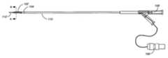
- FIG. 1shows a directional radiation delivery catheter that can be used with the present invention.
- FIG. 2shows a cross-sectional view of the radiation delivery catheter of FIG. 1 taken along line A—A.
- FIG. 3shows a radiation source wire that can be inserted into the radiation delivery catheter of FIG. 1 .
- FIG. 4shows a simplified block diagram of an intravascular ultrasound (IVUS) system in accordance with the present invention.
- IVUSintravascular ultrasound
- FIG. 5shows an IVUS image along with makers used in accordance with the present invention.
- FIG. 7shows an IVUS image having a reference radiation isodose curve in accordance with one embodiment of the present invention.
- FIG. 8shows a simplified flowchart highlighting the steps taken in accordance with the present invention.
- Catheter 100includes a catheter shaft 110 , an IVUS transducer assembly 104 mounted on the shaft and a directional radiation shield 102 located at the distal end of the catheter.
- a radiation lumen 108extends along the majority of the catheter's length.
- An electrical connector 106interconnects the IVUS transducer assembly 104 to an IVUS system (shown in FIG. 4 ).
- a swivel tip 112having a guide wire lumen.
- the swivel tip 112minimizes torquing of the catheter 100 during movement of the catheter through tight vessel bends.
- the preferred directional radiation delivery catheter 100is described in a U.S. patent application entitled “An Intravascular Radiation Delivery Device”, having Ser. No. 08/827,489 and filed on Mar. 28, 1997, to Ciezki, et al. which is hereby incorporated by reference as if fully set forth herein.
- Radiation delivery catheter 100includes a shield or attenuator section 102 shown in cross section in FIG. 2 .
- Shield 102is provided along a predefined length (e.g., 25 millimeters) and is wrapped around a portion of the catheter (e.g., about 235 degrees around the catheter).
- the shield 102can comprise a piece of gold foil located within the catheter body.
- a window or non-shielded portion 202(e.g., 125 degrees) allows for the radiation to be directed or focused as explained in detail in the above noted patent application.
- FIG. 3there is shown a radiation source wire 300 that can be inserted into the catheter lumen 108 , the radiation source wire 300 is fed into catheter 100 until radiation coil 308 reaches the radiation delivery area located at the distal end of the catheter close to shield 102 .
- Source wire 300includes a tapered core wire 302 and a source tip 306 .
- a radiopague source band 304allows an IVUS system operator to determine that the source wire has been properly inserted into catheter 100 .
- a radiation source coil 308preferably formed from Rhenium or Tungsten is activated with radiation as is known in the art.
- the inventionwill automatically adjust the dose rates for the particular source wire used, since the activation date of the source wire is entered into the IVUS system 400 as will be described further below.
- the IVUS image collectedis provided with two radiation shield marker lines 502 that indicate the boundaries of the unshielded area 514 of catheter 100 when the radiation boundaries are activated.
- the radiation shield maker lines 502can be activated on the display by performing a command key sequence via the IVUS system keyboard. Marker lines 502 bound the window area 202 of the catheter and allow the attending physician to know where the shielded portion 516 and unshielded portion 514 of the directional catheter lie in relation to the gathered image.
- the attending physiciancan then torque the catheter in order to adjust the IVUS image according to the stenosis that has been detected.
- the shielded portion 516 of the catheterwill typically be torqued so that it is closest to the area of the lumen that is closest to the vessel wall. This allows the non-shielded or window portion 514 to be pointed or directed to the area of the vessel that has the most occlusion.
- the physicianenters the radiation measurement mode and selects a reference or normalization point dose level 508 (denoted as “R”) on the image. This can be done by using the track ball or mouse which is part of user controls 404 which moves a on-screen cursor to a particular area on the image.
- a prompt window 602 as shown in FIG. 6is displayed on monitor 406 .
- the windowprompts the physician to enter the activation date of the radiation source wire 300 , the activity level of the wire and the dosage level at the reference point that is being selected. This helps to serve as a redundant check of the source delivery carton, which displays the activation date and activity level of the source wire 300 .
- the date and time of creation of the source wire 300can be stored in the catheter's EPROM, which is located within electrical connector 106 . This assumes that the radiation delivery catheter is matched to a particular source wire 300 .
- a default reference dosage level for the reference point 508is set to a default level of 30 Gray (Gy) in the system, which has been found to be an acceptable dosage level ceiling.
- GrayGray
- the radiation dosage level at the reference pointcan be adjusted via widow 602 .
- the physicianwill typically select an area on the vessel as shown in the image 500 that he wants to use as the dosage ceiling, in the example shown, it could be the external elastic lamina (EEL) nearest the catheter.
- EELexternal elastic lamina
- one or more isodose curves 704are added to the image that is displayed.
- the reference dosage curve for marker 508is shown
- This isodose curvecan be generated based on simulation files for the particular radiation source that will be applied (e.g., 188 W/ 188 Re, etc.). These simulation files can be stored in memory section 414 . This reference dosage level curve will help the physician visualize along what part of the image, the reference dosage level of 30 Gy will be applied.
- step 806several other points/markers 504 , 506 and 510 are selected and placed on the IVUS image or images. These markers can be placed on the same IVUS image 500 or other images that have been collected of the targeted site. These other points allow a physician to see the dosage levels that will be applied to several points of interest at one time. The markers can be moved and the dosage rates 522 , 520 and 518 associated with the markers can be immediately updated on the screen.
- one or more isodose curvessuch as curve 704 , can also be displayed over the IVUS image(s).
- the IVUS systemwill prompt the physician to insert the source wire 300 into the patient via the delivery catheter 100 .
- the systemwill let him know how long to maintain the source wire placed in the patient in order to achieve the desired dosage levels previously selected.
- the system 400will notify the physician to remove the source wire, this alert can be audible via speaker 412 and/or visual using display 406 .
- the present inventionallows physicians to get a quick understanding of the dosage levels that will be applied at different points of interest in a treatment site.
- the dosage information displayed at the different points of interest on an IVUS imageallow the physician to adjust the treatment dosage in a quick and easy fashion, using well known point and click steps.
- the dosage table(s) 416 for different source wires 300can be stored in the memory section 414 of system 400 , an intravascular brachytherapy lab can use different radiation source wires and still take advantage of the present invention.
- the dosage tables 416can be linked to different catheters either via manual entry as discussed above, or by automatically reading information stored in either the delivery catheter 100 or source wire 300 . As discussed, the dosage tables can take into account the shielding effects of directional shields 102 found in some radiation delivery catheters, such as catheter 300 .
- the use of directional cathetersis not required to practice all aspects of the present invention, they are beneficial to use given that most stenosis are typically non-centered with respect to the vessel lumen.
- Overall the present inventionprovides a simple and easy to use radiation treatment planning aid that can reduce the time physicians take per brachytherapy procedure.
- the dose table informationis automatically updated by system 400 given the remaining half life of the source wire 300 at the time of use.
- the visual presentation of dose levels at selected point in IVUS image(s) coupled with the automatic dose table updatinghelps reduce the time it takes to formulate a treatment plan.
- the inclusion of on-screen markershelps the physician visualize the dosage levels at critical or important point of the stenosis.
- the displaying of the dosage levels at these selected pointscan help the physician adjust the treatment plan quickly by simply dragging the markers to different location in the image(s). Given this, the present invention can help reduce health care costs, and minimize the inconvenience to patients.
Landscapes
- Health & Medical Sciences (AREA)
- Engineering & Computer Science (AREA)
- Biomedical Technology (AREA)
- Pathology (AREA)
- Nuclear Medicine, Radiotherapy & Molecular Imaging (AREA)
- Radiology & Medical Imaging (AREA)
- Life Sciences & Earth Sciences (AREA)
- Animal Behavior & Ethology (AREA)
- General Health & Medical Sciences (AREA)
- Public Health (AREA)
- Veterinary Medicine (AREA)
- Radiation-Therapy Devices (AREA)
- Ultra Sonic Daignosis Equipment (AREA)
Abstract
Description
Claims (13)
Priority Applications (1)
| Application Number | Priority Date | Filing Date | Title |
|---|---|---|---|
| US09/505,388US6494835B1 (en) | 2000-02-16 | 2000-02-16 | Method and apparatus for intravascular brachytherapy treatment planning |
Applications Claiming Priority (1)
| Application Number | Priority Date | Filing Date | Title |
|---|---|---|---|
| US09/505,388US6494835B1 (en) | 2000-02-16 | 2000-02-16 | Method and apparatus for intravascular brachytherapy treatment planning |
Publications (1)
| Publication Number | Publication Date |
|---|---|
| US6494835B1true US6494835B1 (en) | 2002-12-17 |
Family
ID=24010106
Family Applications (1)
| Application Number | Title | Priority Date | Filing Date |
|---|---|---|---|
| US09/505,388Expired - Fee RelatedUS6494835B1 (en) | 2000-02-16 | 2000-02-16 | Method and apparatus for intravascular brachytherapy treatment planning |
Country Status (1)
| Country | Link |
|---|---|
| US (1) | US6494835B1 (en) |
Cited By (16)
| Publication number | Priority date | Publication date | Assignee | Title |
|---|---|---|---|---|
| US20040068157A1 (en)* | 2002-10-04 | 2004-04-08 | Scimed Life Systems, Inc. | Method and apparatus for the delivery of brachytherapy |
| DE102004008373B3 (en)* | 2004-02-20 | 2005-09-29 | Siemens Ag | Apparatus for performing and monitoring endovascular brachytherapy |
| US20050261541A1 (en)* | 2004-05-20 | 2005-11-24 | Henderson Douglass L | Directionally emitting radioactive sources for brachytherapy |
| WO2007060050A1 (en)* | 2005-11-24 | 2007-05-31 | Siemens Aktiengesellschaft | Device for x-ray brachytherapy, and method for positioning a probe introduced into a body for x-ray brachytherapy |
| WO2007060051A1 (en)* | 2005-11-24 | 2007-05-31 | Siemens Aktiengesellschaft | Device for x-ray brachytherapy, and method for positioning a probe introduced into a body for x-ray brachytherapy |
| US7255678B2 (en) | 2002-10-10 | 2007-08-14 | Visualsonics Inc. | High frequency, high frame-rate ultrasound imaging system |
| US20090248034A1 (en)* | 2008-03-28 | 2009-10-01 | Medtronic Vascular, Inc. | Method of Diagnosing and Treating Benign Prostatic Hyperplasia |
| US20100036471A1 (en)* | 2008-08-05 | 2010-02-11 | Medtronic Vascular, Inc. | Method of Diagnosing and Treating Lower Urinary Tract Symptoms |
| US7674228B2 (en) | 2004-03-01 | 2010-03-09 | Sunnybrook And Women's College Health Sciences Centre | System and method for ECG-triggered retrospective color flow ultrasound imaging |
| WO2010138463A1 (en)* | 2009-05-29 | 2010-12-02 | Boston Scientific Scimed, Inc. | Systems and methods for implementing a data management system for catheter-based imaging systems |
| DE102010020352A1 (en)* | 2010-05-12 | 2011-11-17 | Carl Zeiss Surgical Gmbh | Method for generating and / or providing data for a tissue treatment |
| US8641210B2 (en) | 2011-11-30 | 2014-02-04 | Izi Medical Products | Retro-reflective marker including colored mounting portion |
| US8661573B2 (en) | 2012-02-29 | 2014-03-04 | Izi Medical Products | Protective cover for medical device having adhesive mechanism |
| US8663210B2 (en) | 2009-05-13 | 2014-03-04 | Novian Health, Inc. | Methods and apparatus for performing interstitial laser therapy and interstitial brachytherapy |
| US20150182144A1 (en)* | 2012-08-04 | 2015-07-02 | Koninklijke Philips N.V. | Quantifying Probe Deflection For Improved Catheter Identification |
| US11744640B2 (en)* | 2021-06-24 | 2023-09-05 | Gradient Denervation Technologies Sas | Systems and methods for applying energy to denervate a pulmonary artery |
Citations (4)
| Publication number | Priority date | Publication date | Assignee | Title |
|---|---|---|---|---|
| US5651366A (en)* | 1994-09-19 | 1997-07-29 | Board Of Trustees Of The Leland Stanford Junior University | Forward viewing ultrasonic imaging catheter |
| US5840008A (en)* | 1995-11-13 | 1998-11-24 | Localmed, Inc. | Radiation emitting sleeve catheter and methods |
| US5882291A (en)* | 1996-12-10 | 1999-03-16 | Neocardia, Llc | Device and method for controlling dose rate during intravascular radiotherapy |
| US6077213A (en)* | 1997-03-28 | 2000-06-20 | Navius Corporation | Intravascular radiation delivery device |
- 2000
- 2000-02-16USUS09/505,388patent/US6494835B1/ennot_activeExpired - Fee Related
Patent Citations (4)
| Publication number | Priority date | Publication date | Assignee | Title |
|---|---|---|---|---|
| US5651366A (en)* | 1994-09-19 | 1997-07-29 | Board Of Trustees Of The Leland Stanford Junior University | Forward viewing ultrasonic imaging catheter |
| US5840008A (en)* | 1995-11-13 | 1998-11-24 | Localmed, Inc. | Radiation emitting sleeve catheter and methods |
| US5882291A (en)* | 1996-12-10 | 1999-03-16 | Neocardia, Llc | Device and method for controlling dose rate during intravascular radiotherapy |
| US6077213A (en)* | 1997-03-28 | 2000-06-20 | Navius Corporation | Intravascular radiation delivery device |
Cited By (39)
| Publication number | Priority date | Publication date | Assignee | Title |
|---|---|---|---|---|
| US7041047B2 (en)* | 2002-10-04 | 2006-05-09 | Boston Scientific Scimed, Inc. | Method and apparatus for the delivery of brachytherapy |
| US20040068157A1 (en)* | 2002-10-04 | 2004-04-08 | Scimed Life Systems, Inc. | Method and apparatus for the delivery of brachytherapy |
| US8827907B2 (en) | 2002-10-10 | 2014-09-09 | Fujifilm Sonosite, Inc. | High frequency, high frame-rate ultrasound imaging system |
| US7255678B2 (en) | 2002-10-10 | 2007-08-14 | Visualsonics Inc. | High frequency, high frame-rate ultrasound imaging system |
| DE102004008373B3 (en)* | 2004-02-20 | 2005-09-29 | Siemens Ag | Apparatus for performing and monitoring endovascular brachytherapy |
| US8231516B2 (en) | 2004-02-20 | 2012-07-31 | Siemens Aktiengesellschaft | Device for applying and monitoring of endovascular brachytherapy |
| US7674228B2 (en) | 2004-03-01 | 2010-03-09 | Sunnybrook And Women's College Health Sciences Centre | System and method for ECG-triggered retrospective color flow ultrasound imaging |
| US20050261541A1 (en)* | 2004-05-20 | 2005-11-24 | Henderson Douglass L | Directionally emitting radioactive sources for brachytherapy |
| WO2005115543A1 (en)* | 2004-05-20 | 2005-12-08 | Wisconsin Alumni Research Foundation | Directionally emitting radioactive sources for brachytherapy |
| US7762940B2 (en)* | 2004-05-20 | 2010-07-27 | Wisconsin Alumni Research Foundation | Directionally emitting radioactive sources for brachytherapy |
| WO2007060051A1 (en)* | 2005-11-24 | 2007-05-31 | Siemens Aktiengesellschaft | Device for x-ray brachytherapy, and method for positioning a probe introduced into a body for x-ray brachytherapy |
| US20090131789A1 (en)* | 2005-11-24 | 2009-05-21 | Jens Fehre | Device for x-ray brachytherapy, and method for positioning a probe introduced into a body for x-ray brachytherapy |
| US20080275341A1 (en)* | 2005-11-24 | 2008-11-06 | Siemens Aktiengesellschaft | Device for X-Ray Brachytherapy, and Method for Positioning a Probe Introduced Into a Body for X-Ray Brachytherapy |
| US9162080B2 (en)* | 2005-11-24 | 2015-10-20 | Siemens Aktiengesellschaft | Device for X-ray brachytherapy, and method for positioning a probe introduced into a body for X-ray brachytherapy |
| WO2007060050A1 (en)* | 2005-11-24 | 2007-05-31 | Siemens Aktiengesellschaft | Device for x-ray brachytherapy, and method for positioning a probe introduced into a body for x-ray brachytherapy |
| US20090248034A1 (en)* | 2008-03-28 | 2009-10-01 | Medtronic Vascular, Inc. | Method of Diagnosing and Treating Benign Prostatic Hyperplasia |
| US20100036471A1 (en)* | 2008-08-05 | 2010-02-11 | Medtronic Vascular, Inc. | Method of Diagnosing and Treating Lower Urinary Tract Symptoms |
| US8663210B2 (en) | 2009-05-13 | 2014-03-04 | Novian Health, Inc. | Methods and apparatus for performing interstitial laser therapy and interstitial brachytherapy |
| US20100305442A1 (en)* | 2009-05-29 | 2010-12-02 | Boston Scientific Scimed, Inc. | Systems and methods for implementing a data management system for catheter-based imaging systems |
| WO2010138463A1 (en)* | 2009-05-29 | 2010-12-02 | Boston Scientific Scimed, Inc. | Systems and methods for implementing a data management system for catheter-based imaging systems |
| US20130058460A1 (en)* | 2010-05-12 | 2013-03-07 | Carl Zeiss Meditec Ag | Method of generating and/or providing data for tissue treatment |
| US9108046B2 (en)* | 2010-05-12 | 2015-08-18 | Carl Zeiss Meditec Ag | Method of generating and/or providing data for tissue treatment |
| DE102010020352A1 (en)* | 2010-05-12 | 2011-11-17 | Carl Zeiss Surgical Gmbh | Method for generating and / or providing data for a tissue treatment |
| US8668344B2 (en) | 2011-11-30 | 2014-03-11 | Izi Medical Products | Marker sphere including edged opening to aid in molding |
| US8641210B2 (en) | 2011-11-30 | 2014-02-04 | Izi Medical Products | Retro-reflective marker including colored mounting portion |
| US8651274B2 (en) | 2011-11-30 | 2014-02-18 | Izi Medical Products | Packaging for retro-reflective markers |
| US8668345B2 (en) | 2011-11-30 | 2014-03-11 | Izi Medical Products | Retro-reflective marker with snap on threaded post |
| US8668343B2 (en) | 2011-11-30 | 2014-03-11 | Izi Medical Products | Reflective marker with alignment feature |
| US8668342B2 (en) | 2011-11-30 | 2014-03-11 | Izi Medical Products | Material thickness control over retro-reflective marker |
| US8672490B2 (en) | 2011-11-30 | 2014-03-18 | Izi Medical Products | High reflectivity retro-reflective marker |
| US8662684B2 (en) | 2011-11-30 | 2014-03-04 | Izi Medical Products | Radiopaque core |
| US9964649B2 (en) | 2011-11-30 | 2018-05-08 | Izi Medical Products | Packaging for retro-reflective markers |
| US9085401B2 (en) | 2011-11-30 | 2015-07-21 | Izi Medical Products | Packaging for retro-reflective markers |
| US8646921B2 (en) | 2011-11-30 | 2014-02-11 | Izi Medical Products | Reflective marker being radio-opaque for MRI |
| US8661573B2 (en) | 2012-02-29 | 2014-03-04 | Izi Medical Products | Protective cover for medical device having adhesive mechanism |
| US20150182144A1 (en)* | 2012-08-04 | 2015-07-02 | Koninklijke Philips N.V. | Quantifying Probe Deflection For Improved Catheter Identification |
| US11109776B2 (en)* | 2012-08-04 | 2021-09-07 | Koninklijke Philips N.V. | Quantifying probe deflection for improved catheter identification |
| US11744640B2 (en)* | 2021-06-24 | 2023-09-05 | Gradient Denervation Technologies Sas | Systems and methods for applying energy to denervate a pulmonary artery |
| US11950842B2 (en)* | 2021-06-24 | 2024-04-09 | Gradient Denervation Technologies Sas | Systems and methods for applying energy to denervate a pulmonary artery |
Similar Documents
| Publication | Publication Date | Title |
|---|---|---|
| US6494835B1 (en) | Method and apparatus for intravascular brachytherapy treatment planning | |
| US5199939A (en) | Radioactive catheter | |
| US12150796B2 (en) | System and method for controlling x-ray frame rate of an imaging system | |
| US6283910B1 (en) | Method of treating a body vessel or duct with radiation from within the lumen | |
| US6746393B2 (en) | Retrievable, shielded radiotherapy implant | |
| EP1341443B1 (en) | System for positioning a device in a tubular organ | |
| US20030092956A1 (en) | Brachytherapy device assembly and method of use | |
| US10271910B2 (en) | Robotic catheter system with FFR integration | |
| DE102004058008A1 (en) | Guidewire for vascular catheter with improved tracking and navigation | |
| JP2016501085A (en) | Positioning tool | |
| US20080228079A1 (en) | Clinical utilization of contrast agents to define specific areas within the myocardial wall to provide guidance and localization for ablation, cyroablation, or other techniques in patients with post myocardial infarction | |
| Zelefsky et al. | Real-time intraoperative evaluation of implant quality and dose correction during prostate brachytherapy consistently improves target coverage using a novel image fusion and optimization program | |
| EP4197593A1 (en) | Method and apparatus to detect and respond to radiation treatment plan spot weight edits | |
| EP1954352B1 (en) | Device for x-ray brachytherapy | |
| US20030135102A1 (en) | Method and system for registration and guidance of intravascular treatment | |
| Mansour | The new operating room environment | |
| Carlier et al. | Comparison of brachytherapy strategies based on dose-volume histograms derived from quantitative intravascular ultrasound | |
| JP3091328B2 (en) | Medical guidewire | |
| CL Lim | Antegrade techniques for chronic total occlusions | |
| Umans et al. | The mechanism of directional coronary atherectomy | |
| Baumgart et al. | Successful reduction of in-stent restenosis in long lesions using β-radiation—subanalysis from the RENO registry | |
| Carlier et al. | Clinical decision making tools for IVUS-based treatment planning clinical decision making tools for IVUS-based treatment planning | |
| Kirisits et al. | Dose–volume histograms based on serial intravascular ultrasound: a calculation model for radioactive stents | |
| Bloch et al. | Dosimetry for an Sr90/Y90 source train used for intravascular radiation of a hemodialysis graft | |
| Chudow et al. | Decrease in radiation exposure during cardiac implantable electronic device (CIED) implantation with modern imaging platform |
Legal Events
| Date | Code | Title | Description |
|---|---|---|---|
| AS | Assignment | Owner name:ENDOSONICS CORPORATION, CALIFORNIA Free format text:ASSIGNMENT OF ASSIGNORS INTEREST;ASSIGNOR:BLEAM, DAVID;REEL/FRAME:010846/0731 Effective date:20000525 Owner name:CLEVELAND CLINIC FOUNDATION, THE A NON-PROFIT CORP Free format text:ASSIGNMENT OF ASSIGNORS INTEREST;ASSIGNORS:CIEZKI, JAY P.;URS, HAFELI;REEL/FRAME:010846/0722 Effective date:20000523 | |
| AS | Assignment | Owner name:JOMED INC., CALIFORNIA Free format text:CHANGE OF NAME;ASSIGNOR:ENDOSONICS CORPORATION;REEL/FRAME:013296/0056 Effective date:20001201 | |
| AS | Assignment | Owner name:VOLCANO THERAPEUTICS, INC., CALIFORNIA Free format text:ASSIGNMENT OF ASSIGNORS INTEREST;ASSIGNOR:JOMED INC.;REEL/FRAME:014539/0729 Effective date:20030717 Owner name:VOLCANO THERAPEUTICS, INC.,CALIFORNIA Free format text:ASSIGNMENT OF ASSIGNORS INTEREST;ASSIGNOR:JOMED INC.;REEL/FRAME:014539/0729 Effective date:20030717 | |
| REMI | Maintenance fee reminder mailed | ||
| LAPS | Lapse for failure to pay maintenance fees | ||
| STCH | Information on status: patent discontinuation | Free format text:PATENT EXPIRED DUE TO NONPAYMENT OF MAINTENANCE FEES UNDER 37 CFR 1.362 | |
| FP | Lapsed due to failure to pay maintenance fee | Effective date:20061217 |