US6494270B1 - Apparatus and method for mulching and cultivating agricultural fields - Google Patents
Apparatus and method for mulching and cultivating agricultural fieldsDownload PDFInfo
- Publication number
- US6494270B1 US6494270B1US09/636,364US63636400AUS6494270B1US 6494270 B1US6494270 B1US 6494270B1US 63636400 AUS63636400 AUS 63636400AUS 6494270 B1US6494270 B1US 6494270B1
- Authority
- US
- United States
- Prior art keywords
- drum
- blades
- drums
- frame
- rotation
- Prior art date
- Legal status (The legal status is an assumption and is not a legal conclusion. Google has not performed a legal analysis and makes no representation as to the accuracy of the status listed.)
- Expired - Lifetime
Links
Images


Classifications
- A—HUMAN NECESSITIES
- A01—AGRICULTURE; FORESTRY; ANIMAL HUSBANDRY; HUNTING; TRAPPING; FISHING
- A01B—SOIL WORKING IN AGRICULTURE OR FORESTRY; PARTS, DETAILS, OR ACCESSORIES OF AGRICULTURAL MACHINES OR IMPLEMENTS, IN GENERAL
- A01B39/00—Other machines specially adapted for working soil on which crops are growing
- A01B39/12—Other machines specially adapted for working soil on which crops are growing for special purposes, e.g. for special culture
- A01B39/16—Other machines specially adapted for working soil on which crops are growing for special purposes, e.g. for special culture for working in vineyards, orchards, or the like ; Arrangements for preventing damage to vines
- A01B39/163—Other machines specially adapted for working soil on which crops are growing for special purposes, e.g. for special culture for working in vineyards, orchards, or the like ; Arrangements for preventing damage to vines comprising rotating tools
- A—HUMAN NECESSITIES
- A01—AGRICULTURE; FORESTRY; ANIMAL HUSBANDRY; HUNTING; TRAPPING; FISHING
- A01B—SOIL WORKING IN AGRICULTURE OR FORESTRY; PARTS, DETAILS, OR ACCESSORIES OF AGRICULTURAL MACHINES OR IMPLEMENTS, IN GENERAL
- A01B35/00—Other machines for working soil not specially adapted for working soil on which crops are growing
- A01B35/20—Tools; Details
- A01B35/28—Rotating tools; Mounting rotating tools
- A—HUMAN NECESSITIES
- A01—AGRICULTURE; FORESTRY; ANIMAL HUSBANDRY; HUNTING; TRAPPING; FISHING
- A01B—SOIL WORKING IN AGRICULTURE OR FORESTRY; PARTS, DETAILS, OR ACCESSORIES OF AGRICULTURAL MACHINES OR IMPLEMENTS, IN GENERAL
- A01B39/00—Other machines specially adapted for working soil on which crops are growing
- A01B39/08—Other machines specially adapted for working soil on which crops are growing with rotating tools such as weeding machines
Definitions
- the present inventionrelates to agricultural machines and operations, and in particular to a ground driven apparatus and method for mulching fodder remaining within valley portions of an agricultural bed as in a sugar cane field which has had sugar cane cut and harvested.
- Shwezdiscloses an agricultural implement that cuts and shreds the stalks of plants by bending and pressing the stalks onto the ground and subsequently shredding them with swinging motor driven, hinged cutter blades. Cultivating the unplanted soil between crop rows to control weed growth, to mulch, and to aerate the soil is desirable for optimum plant growth, as described in U.S. Pat. No.
- an apparatuscomprising a frame adapted for moving across an agricultural field and at least two drums rotatably carried by the frame.
- Each of the drumsis freely rotatable about an axis of rotation, and each includes a rolling surface for operating on a ground surface above which the frame is moving.
- a plurality of bladesextends outward from the rolling surface for penetrating the ground surface.
- Each of the plurality of bladeshas an edge in spaced relation to the rolling surface and is oriented at an angle between zero degrees and ninety degrees to the axis of rotation.
- One of the at least two drumsincludes the plurality of blades having one angle which differs from the angle for the plurality of blades of a second of the at least two drums.
- One embodiment of the apparatusincludes the at least two drums, in combination, forming a drum pair, with one drum pair carried at a forward portion of the frame and a second drum pair carried at an aft portion of the frame.
- the weight of the frame and drumsare generally sufficient to allow the blades to penetrate the ground with the rolling surface of the drum freely rolling on the ground surface. With extremely hard or compact soils, the drums may be filled with water for adding weight to the apparatus.
- a method aspect of the inventioncomprises freely rotating first and second drums about their respective axis of rotation, wherein each of the first and second drums includes a rolling surface for operating over a ground surface and a plurality of blades extending from the rolling surface for penetrating the ground surface.
- the first drumhas the blades angled orthogonal to the blades on the second drum.
- the first and second drumsare straddled transversely across and proximate the crop row for permitting the first and second drums to freely roll on opposing sides of the crop row.
- the drumsare then freely rolled over the ground surface for having the plurality of blades to mulch within opposing ground portions on each side of the crop row.
- FIG. 1is a right front perspective view of one embodiment for a mulching and cultivating apparatus in accordance with the present invention
- FIG. 2is a rear elevation view of a rotating drum pair of the embodiment of FIG. 1, the front being a mirror image;
- FIG. 3is a side view of the embodiment of FIG. 1, illustrating a transportation wheel assembly in a transporting position
- FIG. 4is the side view of FIG. 3, illustrating a retracted transportation wheel assembly during use of the apparatus in a mulching and cultivating operation with a tongue assembly positioned for a weight biasing onto a rear drum pair;
- FIG. 5is the side view of FIG. 3, illustrating a retracted transportation wheel assembly during use of the apparatus in a mulching and cultivating operation with a tongue assembly positioned for a weight biasing onto a front drum pair;
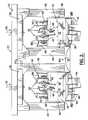
- FIG. 6is a cross-section view of an agricultural field illustrating, by way of example, crop rows of a sugar can bed and space between crop rows typically containing cut cane stems after a sugar cane harvesting;
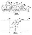
- FIG. 7is a partial illustrative plan view of a sugar cane bed illustrating a crop row and bed middles/valley portions, thereof.
- the apparatus 10comprises a frame 12 and a tongue assembly 14 which provides means for attaching the frame to a tractor, by way of example, using a tractor hitch 16 .
- the apparatus 10 herein described by way of exampleis adapted to be pulled by the tractor but as will become clear to one skilled in the art, alternate driving means including harvesting type self driven vehicles, or a vehicle adapted to push the apparatus 10 may also be used, in addition to a self propelled version without departing from the intent and teachings of the present invention.
- the apparatus 10further includes a first carriage 18 and a second carriage 20 moveably carried by the frame 12 for affixing thereto at a preselected orientation 22 .
- each of the first and second carriages 18 , 20have first and second arms, 24 , 26 , and 28 , 30 , respectively, in a spaced relation for receiving a drum 32 , 34 therebetween.
- the first drum 32 and the second drum 34carried by the first and second carriages 18 , 20 , respectively, are each freely rotatable on first and second axles 36 , 38 extending between the first and second arms 24 , 26 and 28 , 30 of each carriage.
- the drums 32 , 34are cylindrical in shape and define a rolling surface 40 , 42 for preferably operating on a ground surface 44 above which the frame 12 is moving. As illustrated by way of example with reference again to FIGS.
- the first carriage 18is spaced from the second carriage 20 and carried by the frame 12 generally transverse to a direction of travel 46 for the frame, thus permitting the drums 32 , 34 to freely roll in contact with the ground surface 44 on opposing interspace sides, or valley portions 48 , 50 of a crop row 52 , as illustrated again with reference to FIG. 2 .
- the shape of the crop row 52 and interspace ground 48 , 50are herein described for discussion only and are not intended to be exact.
- the first and second carriage 18 , 20are slidably as shown by arrows 51 and rotatably as shown by arrows 53 carried by the frame 12 for securing each carriage 18 , 20 and thus each drum 32 , 34 at the preselected orientation 22 desired for mulching and cultivating the ground surface 44 within the valley portions 48 , 50 .
- each drum 32 , 34includes a plurality of blades 54 , 56 carried on the rolling surface 40 , 42 , respectively.
- each of the plurality of blades 54 , 56extends radially outward from the axle 36 , 38 and includes a cutting edge 58 , 60 oriented at first and second non-zero angles 62 , 64 to the respective axle (axes of rotation).
- the first non-zero angle 62 for the first drum 32differs from the second non-zero angle 64 of the second drum 34 , placing the blades 54 of the first drum orthogonal to the blades 56 on the second drum.
- the blades 54 , 56are formed from a plate 55 having a tapered cutting edge 59 for penetrating the ground surface 44 and an opposing edge 61 welded to the rolling surface 40 , 42 of each drum 32 , 34 .
- a gusset 63 welded to the plate 55 and the rolling surface 40 , 42provides added strength and stiffness to the plate and the attachment of the plate to the rolling surface.
- one embodiment of the present inventionincludes the first and second carriages 18 , 20 and drums 32 , 34 , in combination, forming a drum pair, with the apparatus 10 including one drum pair 66 carried at a forward portion 68 of the frame 12 and a second drum pair 70 carried at an aft portion 72 of the frame.
- the one drum pair 66 and the second drum pair 70have their respective drums 32 , 34 within one valley portion 48 , by way of example, and include blades 54 , 56 that are orthogonal to each other.
- first drum 32 of the first drum pair 66rolls within the same valley portion 48 as the second drum 34 of the second drum pair 70 allowing the blades of the first drum pair to throw ground material to the left and the blades of the second drum pair to throw ground material to the right, by way of example.
- the apparatus 10further comprises a wheel assembly 74 rotatably carried by the frame 12 for movement of the wheel assembly from a transporting position 76 , wherein a wheel 78 carried by the wheel assemble contacts a roadway 80 for transporting the apparatus thereover with the cutting edges 58 , 60 of the blades 54 , 56 out of contact with the roadway, to a retracted position 82 , wherein the wheel 78 is positioned for allowing the blades 54 , 56 to be placed in contact with the ground surface 44 being cultivated.
- a tandem wheel assembly having multiple wheelsis employed with a hydraulic drive mechanism 84 operable with the wheel assembly 74 for providing movement thereto.
- the tongue assembly 14provides means for attaching the frame 12 to a tractor for pulling the apparatus 10 .
- the tongue assembly 14is pivotal with respect to the frame 12 for providing a shift in the center of gravity between the forward to the aft portions 68 , 72 as desired, thus allowing a preselected load onto the ground surface 44 for the one drum pair 66 and the second drum pair 70 .
- the tongue assembly 14includes an elongate member 86 having a proximal end 88 pivotally attached to the frame 12 and a distal end 90 having the tractor hitch 16 adapted to be connected to the tractor.
- a telescoping arm 92is pivotally connected between the elongate member 86 and the frame 12 , wherein a preselected telescoping length adjustment of the arm 92 causes the frame to be set at a desired pitch ranging between a forward pitch to an aft pitch, and thus a biasing of weight distribution through the movement of the center of gravity.
- a second hydraulic drive mechanism 94is used to provide telescoping length adjustments.
- each drum 32 , 34is a hollow cylinder having a chamber which is filled with water through a bung 100 in a side wall 102 of the drum 32 , 34 when added weight is desired for the apparatus 10 operating in extremely compacted soil.
- drums 32 , 34 of the one drum pair 66 and the second drum pair 70have their rolling surface 40 , 42 roll on the ground surface 44 to permit full penetration of the blades 54 , 56 .
- Adding weight to the apparatus 10 by carrying water within the drums 32 , 34allows the blades to penetrate more compacted soils.
- a method of mulching and cultivating the valley portions 48 , 50 of crop rows 52 , 53 where sugar cane 104 has been cut and harvested resulting in the fodder 106 including cane stalks 108 undesirably dispersed over the valley portions on the opposing sides 48 , 50 as earlier described with reference to FIG. 2,includes freely rotating the drums 32 , 34 for operating over the valley portions 48 , 50 and causing the plurality of blades 54 , 56 , orthogonally carried within a single valley portion 48 , 50 as earlier described, to penetrate the ground surface 44 cutting the cane stalks 108 and mulching the ground material/soil within the valley portions 48 , 50 .
- the carriages 18 , 20may be rotated at an acute angle to the direction of travel 46 along the crop row 52 and fixed at the acute angle to further angle the blades and enhance the cultivating by having the blades be more or less aggressive in throwing the dirt during the free rotation of the drums 32 , 34 .
- the fodder 106is cut into small pieces which encourages a large percentage to rot.
- the blades 54 , 56penetrate depths into the ground 44 that fractures a full width of the valley portions 48 , 50 or middle between the crop row 52 , thus avoiding standing water, permitting fertilizer to seep in, and water to seep in, all encouraging roots to desirably grow downward toward the water and nutrients instead of growing into only the first few inches of soil.
- Use of the embodiment of the present invention herein describedhas eliminated the need to disk cane fields upwards of eight to eleven passes in order to adequately cut-up fodder and then have to chisel plow the field.
- the apparatusavoids fodder balling up, enables mulching to a desired level within a single pass, provides a wider soil fracture zone than typically seen using the discing method, fracturing 18′′ to 24′′ deep into the ground using ten inch long blades.
- the apparatus herein describedhas resulted in a consistent leveling and fracturing for a full width of the interspace between sugar cane beds which allows for an even and consistent flow of water during flood irrigation. Fodder is cut and the fodder is mixed into the soil to enhance rotting procedure and build humus in soil.
- the apparatus 10effectively operates at pulling speeds of 7-11 mph making the single pass even more efficient especially when one concedes that disking speeds are generally at 3-5 mph and need up to eleven passes to cultivate the same field.
- the diameter of the drums and length of bladesmay be varied to achieve a desired speed of rotation of the drums and ground penetration for the blades.
Landscapes
- Life Sciences & Earth Sciences (AREA)
- Engineering & Computer Science (AREA)
- Mechanical Engineering (AREA)
- Soil Sciences (AREA)
- Environmental Sciences (AREA)
- Soil Working Implements (AREA)
Abstract
Description
Claims (45)
Priority Applications (1)
| Application Number | Priority Date | Filing Date | Title |
|---|---|---|---|
| US09/636,364US6494270B1 (en) | 1999-08-13 | 2000-08-11 | Apparatus and method for mulching and cultivating agricultural fields |
Applications Claiming Priority (2)
| Application Number | Priority Date | Filing Date | Title |
|---|---|---|---|
| US14878599P | 1999-08-13 | 1999-08-13 | |
| US09/636,364US6494270B1 (en) | 1999-08-13 | 2000-08-11 | Apparatus and method for mulching and cultivating agricultural fields |
Publications (1)
| Publication Number | Publication Date |
|---|---|
| US6494270B1true US6494270B1 (en) | 2002-12-17 |
Family
ID=26846165
Family Applications (1)
| Application Number | Title | Priority Date | Filing Date |
|---|---|---|---|
| US09/636,364Expired - LifetimeUS6494270B1 (en) | 1999-08-13 | 2000-08-11 | Apparatus and method for mulching and cultivating agricultural fields |
Country Status (1)
| Country | Link |
|---|---|
| US (1) | US6494270B1 (en) |
Cited By (14)
| Publication number | Priority date | Publication date | Assignee | Title |
|---|---|---|---|---|
| US6923267B1 (en)* | 2002-12-18 | 2005-08-02 | Abc Groff, Inc. | Linear turf aeration apparatus |
| US6968907B1 (en)* | 2003-12-29 | 2005-11-29 | The United States Of America As Represented By The Secretary Of Agriculture | Smooth rolling cover crop roller |
| US20060048952A1 (en)* | 2004-09-09 | 2006-03-09 | Larry Classen | Turf aerator |
| US20060070750A1 (en)* | 2004-09-09 | 2006-04-06 | Schiller-Pfieffer, Inc. | Turf aerator |
| US20070089888A1 (en)* | 2005-10-26 | 2007-04-26 | Condrey Tommy H | Single pass plow |
| FR2943502A1 (en)* | 2009-03-31 | 2010-10-01 | Hubert Gerber | Plant i.e. vine, folding and plucking device for use with tractor, has cylinder whose external surface comprises blades, which are placed in zig-zag manner with respect to each other |
| WO2011151376A1 (en) | 2010-06-01 | 2011-12-08 | Pubert Henri Sas | Implement with retractable transport wheel |
| ITPN20110064A1 (en)* | 2011-10-03 | 2012-01-02 | Agrimec 3 Snc Di Baraldo Iris & C | ROLL FOR WORKING THE LAND |
| US8201638B1 (en)* | 2011-05-02 | 2012-06-19 | Carl Badger | Agricultural implement |
| CN103583100A (en)* | 2013-11-14 | 2014-02-19 | 安徽淮化股份有限公司 | Cultivator |
| US8714276B2 (en) | 2011-03-11 | 2014-05-06 | Great Plains Manufacturing, Inc. | Soil chopping and leveling system |
| US20150189835A1 (en)* | 2014-01-08 | 2015-07-09 | Deere & Company | Pitched profile pre-cutter tine |
| US20150216105A1 (en)* | 2014-02-05 | 2015-08-06 | University Of Tennessee Research Foundation | Flex roller-crimper for improved management and termination of cover crops and other plant material |
| US10531602B2 (en)* | 2013-03-14 | 2020-01-14 | Claussen Technology, Llc | Implements for displacing ground material |
Citations (20)
| Publication number | Priority date | Publication date | Assignee | Title |
|---|---|---|---|---|
| US2659188A (en) | 1950-03-31 | 1953-11-17 | Haban Joseph | Farm row crop shredder |
| US2663131A (en)* | 1950-08-18 | 1953-12-22 | Clarence A Johnson | Undergrowth destroyer |
| US2870850A (en)* | 1955-06-20 | 1959-01-27 | Dethlefsen Borghild Hartmann | Combined rotary soil cultivator and branch crusher |
| US3193021A (en)* | 1962-08-23 | 1965-07-06 | Roy M Lane | Stalk mulching and disintegrating machine |
| US3538987A (en) | 1964-11-03 | 1970-11-10 | Leslie Ford Williams | Agricultural apparatus for shaped beds |
| US3750758A (en) | 1970-11-13 | 1973-08-07 | J Bancel | Farming implement for ridging |
| US3794123A (en)* | 1972-05-18 | 1974-02-26 | Kelly Mfg Co | Cultivator |
| US3860075A (en)* | 1973-01-11 | 1975-01-14 | Morris Rod Weeder Co Ltd | Row crop rotary rod weeder |
| US4044841A (en) | 1972-12-27 | 1977-08-30 | Smitty's Incorporated | Rotary tiller device adapted for chopping |
| US4260027A (en) | 1978-04-17 | 1981-04-07 | W.E.F.C.O., Inc. | Flail-type mulcher cultivator |
| US4508177A (en)* | 1983-04-29 | 1985-04-02 | Wiser Thayne B | Soil pitting and damming implement and process |
| US4518043A (en) | 1982-08-09 | 1985-05-21 | Jack F. Anderson | Tool apparatus with control to move tool when object approached |
| US4619329A (en)* | 1985-03-12 | 1986-10-28 | Cleon Gorbett | Soil aerator |
| US4690224A (en) | 1985-12-23 | 1987-09-01 | Mark Shwez | Agricultural implement for disposal of crop residue |
| JPH04316401A (en)* | 1991-04-15 | 1992-11-06 | Iseki & Co Ltd | Row spacing adjustment device for multiple tillage equipment |
| WO1993009659A1 (en)* | 1991-11-21 | 1993-05-27 | Humphreys James R | Mulching apparatus |
| US5267517A (en)* | 1992-01-27 | 1993-12-07 | Farmers Tractor And Equipment | Multi function tillage or planting implement |
| US5316088A (en)* | 1992-02-04 | 1994-05-31 | Ries Robert H | Rotary hoe mounting unit for row crop cultivator |
| US5318134A (en)* | 1992-09-17 | 1994-06-07 | Philip Jensen | Irrigation furrow and raised seed bed forming machine |
| US5474135A (en)* | 1994-02-22 | 1995-12-12 | Schlagel Manufacturing, Inc. | Minimum tillage implement |
- 2000
- 2000-08-11USUS09/636,364patent/US6494270B1/ennot_activeExpired - Lifetime
Patent Citations (20)
| Publication number | Priority date | Publication date | Assignee | Title |
|---|---|---|---|---|
| US2659188A (en) | 1950-03-31 | 1953-11-17 | Haban Joseph | Farm row crop shredder |
| US2663131A (en)* | 1950-08-18 | 1953-12-22 | Clarence A Johnson | Undergrowth destroyer |
| US2870850A (en)* | 1955-06-20 | 1959-01-27 | Dethlefsen Borghild Hartmann | Combined rotary soil cultivator and branch crusher |
| US3193021A (en)* | 1962-08-23 | 1965-07-06 | Roy M Lane | Stalk mulching and disintegrating machine |
| US3538987A (en) | 1964-11-03 | 1970-11-10 | Leslie Ford Williams | Agricultural apparatus for shaped beds |
| US3750758A (en) | 1970-11-13 | 1973-08-07 | J Bancel | Farming implement for ridging |
| US3794123A (en)* | 1972-05-18 | 1974-02-26 | Kelly Mfg Co | Cultivator |
| US4044841A (en) | 1972-12-27 | 1977-08-30 | Smitty's Incorporated | Rotary tiller device adapted for chopping |
| US3860075A (en)* | 1973-01-11 | 1975-01-14 | Morris Rod Weeder Co Ltd | Row crop rotary rod weeder |
| US4260027A (en) | 1978-04-17 | 1981-04-07 | W.E.F.C.O., Inc. | Flail-type mulcher cultivator |
| US4518043A (en) | 1982-08-09 | 1985-05-21 | Jack F. Anderson | Tool apparatus with control to move tool when object approached |
| US4508177A (en)* | 1983-04-29 | 1985-04-02 | Wiser Thayne B | Soil pitting and damming implement and process |
| US4619329A (en)* | 1985-03-12 | 1986-10-28 | Cleon Gorbett | Soil aerator |
| US4690224A (en) | 1985-12-23 | 1987-09-01 | Mark Shwez | Agricultural implement for disposal of crop residue |
| JPH04316401A (en)* | 1991-04-15 | 1992-11-06 | Iseki & Co Ltd | Row spacing adjustment device for multiple tillage equipment |
| WO1993009659A1 (en)* | 1991-11-21 | 1993-05-27 | Humphreys James R | Mulching apparatus |
| US5267517A (en)* | 1992-01-27 | 1993-12-07 | Farmers Tractor And Equipment | Multi function tillage or planting implement |
| US5316088A (en)* | 1992-02-04 | 1994-05-31 | Ries Robert H | Rotary hoe mounting unit for row crop cultivator |
| US5318134A (en)* | 1992-09-17 | 1994-06-07 | Philip Jensen | Irrigation furrow and raised seed bed forming machine |
| US5474135A (en)* | 1994-02-22 | 1995-12-12 | Schlagel Manufacturing, Inc. | Minimum tillage implement |
Non-Patent Citations (1)
| Title |
|---|
| Lawson, Lawson Cattle & Equipment Inc.: The Finest in Pasture Aeration and Brush Clearing, USA, 1995. |
Cited By (22)
| Publication number | Priority date | Publication date | Assignee | Title |
|---|---|---|---|---|
| US6923267B1 (en)* | 2002-12-18 | 2005-08-02 | Abc Groff, Inc. | Linear turf aeration apparatus |
| US6968907B1 (en)* | 2003-12-29 | 2005-11-29 | The United States Of America As Represented By The Secretary Of Agriculture | Smooth rolling cover crop roller |
| US20060048952A1 (en)* | 2004-09-09 | 2006-03-09 | Larry Classen | Turf aerator |
| US20060070750A1 (en)* | 2004-09-09 | 2006-04-06 | Schiller-Pfieffer, Inc. | Turf aerator |
| US7100702B2 (en)* | 2004-09-09 | 2006-09-05 | Schiller-Pfeiffer, Inc. | Turf aerator |
| US7341114B2 (en) | 2004-09-09 | 2008-03-11 | Schiller-Pfeiffer, Inc. | Turf aerator |
| US20080149357A1 (en)* | 2004-09-09 | 2008-06-26 | Schiller-Pfeiffer, Inc. | Turf Aerator |
| US7487842B2 (en) | 2004-09-09 | 2009-02-10 | Schiller-Pfeiffer, Inc. | Turf aerator |
| US8235132B2 (en) | 2005-10-26 | 2012-08-07 | Mod-Track Corporation | Single pass plow |
| US20070089888A1 (en)* | 2005-10-26 | 2007-04-26 | Condrey Tommy H | Single pass plow |
| FR2943502A1 (en)* | 2009-03-31 | 2010-10-01 | Hubert Gerber | Plant i.e. vine, folding and plucking device for use with tractor, has cylinder whose external surface comprises blades, which are placed in zig-zag manner with respect to each other |
| WO2011151376A1 (en) | 2010-06-01 | 2011-12-08 | Pubert Henri Sas | Implement with retractable transport wheel |
| CN103118526A (en)* | 2010-06-01 | 2013-05-22 | 皮贝尔亨利股份有限公司 | Equipment with retractable transport wheels |
| CN103118526B (en)* | 2010-06-01 | 2016-10-05 | 皮贝尔亨利股份有限公司 | Equipment with retractable transport wheels |
| US8714276B2 (en) | 2011-03-11 | 2014-05-06 | Great Plains Manufacturing, Inc. | Soil chopping and leveling system |
| US8201638B1 (en)* | 2011-05-02 | 2012-06-19 | Carl Badger | Agricultural implement |
| ITPN20110064A1 (en)* | 2011-10-03 | 2012-01-02 | Agrimec 3 Snc Di Baraldo Iris & C | ROLL FOR WORKING THE LAND |
| US10531602B2 (en)* | 2013-03-14 | 2020-01-14 | Claussen Technology, Llc | Implements for displacing ground material |
| CN103583100A (en)* | 2013-11-14 | 2014-02-19 | 安徽淮化股份有限公司 | Cultivator |
| US20150189835A1 (en)* | 2014-01-08 | 2015-07-09 | Deere & Company | Pitched profile pre-cutter tine |
| US9144200B2 (en)* | 2014-01-08 | 2015-09-29 | Deere & Company | Pitched profile pre-cutter tine |
| US20150216105A1 (en)* | 2014-02-05 | 2015-08-06 | University Of Tennessee Research Foundation | Flex roller-crimper for improved management and termination of cover crops and other plant material |
Similar Documents
| Publication | Publication Date | Title |
|---|---|---|
| US5953895A (en) | Method and apparatus for pulling and chopping plant stalks | |
| US5460229A (en) | Field aerator apparatus | |
| US4187916A (en) | Soil conditioning and seed bed preparing apparatus | |
| US3170421A (en) | Submulcher and planter in combination therewith | |
| US6431287B1 (en) | Soil tiller assembly and method for tilling soil | |
| US4624197A (en) | Minimum tillage toolbar and method for using same | |
| US6494270B1 (en) | Apparatus and method for mulching and cultivating agricultural fields | |
| US4212254A (en) | Tiller planter with modified seed bed finishing implement | |
| CA2375838C (en) | Low-till harrow implement | |
| CA2969875C (en) | Variable tooth coulter blade with sized inserts | |
| GB1601779A (en) | Method and device for mechanically producing seed or plant drills | |
| Singh | Farm machinery | |
| Salokhe et al. | Effect of rotation direction of a rotary tiller on draft and power requirements in a Bangkok clay soil | |
| CA1138700A (en) | Method and implement for loosening the soil | |
| US4199030A (en) | Method and apparatus for farming row crops | |
| Fenster | Stubble mulching with various types of machinery | |
| US4117889A (en) | Apparatus for guiding row crop processing implements | |
| US5303662A (en) | Minimum tillage tool bar and method for using same | |
| US4331204A (en) | Tillage implement | |
| US4884391A (en) | Stalk cutting apparatus | |
| US20220159890A1 (en) | Farm and agriculture equipment | |
| US2669067A (en) | Method of cultivating row crops | |
| WO2019145373A1 (en) | Apparatus for tilling agricultural soils, particularly for preparing for sowing or transplantation, vibrating frame and toothed disk for such apparatus | |
| RU184890U1 (en) | Combined Tillage | |
| US10820462B2 (en) | Variable tooth coulter blade with sized inserts |
Legal Events
| Date | Code | Title | Description |
|---|---|---|---|
| AS | Assignment | Owner name:LAWSON CATTLE & EQUIPMENT, INC., FLORIDA Free format text:ASSIGNMENT OF ASSIGNORS INTEREST;ASSIGNOR:LAWSON, MARCUS G.;REEL/FRAME:011319/0531 Effective date:20001025 | |
| STCF | Information on status: patent grant | Free format text:PATENTED CASE | |
| FPAY | Fee payment | Year of fee payment:4 | |
| AS | Assignment | Owner name:LAWSON MANUFACTURING, INC., FLORIDA Free format text:ASSIGNMENT OF ASSIGNORS INTEREST;ASSIGNOR:LAWSON CATTLE & EQUIPMENT, INC.;REEL/FRAME:018891/0444 Effective date:20070123 | |
| AS | Assignment | Owner name:MARCUS G. LAWSON TRUST (CATHERINE P. LAWSON, TRUST Free format text:ASSIGNMENT OF ASSIGNORS INTEREST;ASSIGNOR:LAWSON MANUFACTURING, INC.;REEL/FRAME:020762/0179 Effective date:20080318 Owner name:CATHERINE P. LAWSON TRUST (CATHERINE P. LAWSON, TR Free format text:ASSIGNMENT OF ASSIGNORS INTEREST;ASSIGNOR:LAWSON MANUFACTURING, INC.;REEL/FRAME:020762/0179 Effective date:20080318 | |
| FPAY | Fee payment | Year of fee payment:8 | |
| FPAY | Fee payment | Year of fee payment:12 |