US6494079B1 - Method and apparatus for characterizing materials by using a mechanical resonator - Google Patents
Method and apparatus for characterizing materials by using a mechanical resonatorDownload PDFInfo
- Publication number
- US6494079B1 US6494079B1US09/800,819US80081901AUS6494079B1US 6494079 B1US6494079 B1US 6494079B1US 80081901 AUS80081901 AUS 80081901AUS 6494079 B1US6494079 B1US 6494079B1
- Authority
- US
- United States
- Prior art keywords
- resonator
- mechanical
- conduit
- fluid composition
- tuning fork
- Prior art date
- Legal status (The legal status is an assumption and is not a legal conclusion. Google has not performed a legal analysis and makes no representation as to the accuracy of the status listed.)
- Expired - Lifetime
Links
- 238000000034methodMethods0.000titleclaimsabstractdescription46
- 239000000463materialSubstances0.000titledescription17
- 239000000203mixtureSubstances0.000claimsabstractdescription102
- 239000012530fluidSubstances0.000claimsabstractdescription76
- 230000004044responseEffects0.000claimsabstractdescription62
- 238000005259measurementMethods0.000claimsabstractdescription33
- 230000000704physical effectEffects0.000claimsabstractdescription9
- 230000001419dependent effectEffects0.000claimsdescription10
- 239000012528membraneSubstances0.000claimsdescription5
- 238000010897surface acoustic wave methodMethods0.000claimsdescription3
- 239000007788liquidSubstances0.000description99
- 239000000126substanceSubstances0.000description31
- 239000010453quartzSubstances0.000description16
- VYPSYNLAJGMNEJ-UHFFFAOYSA-Nsilicon dioxideInorganic materialsO=[Si]=OVYPSYNLAJGMNEJ-UHFFFAOYSA-N0.000description16
- 150000001875compoundsChemical class0.000description14
- 230000008859changeEffects0.000description12
- 238000000576coating methodMethods0.000description12
- 239000011248coating agentSubstances0.000description11
- 230000008878couplingEffects0.000description10
- 238000010168coupling processMethods0.000description10
- 238000005859coupling reactionMethods0.000description10
- 239000013078crystalSubstances0.000description10
- 229920000642polymerPolymers0.000description10
- 238000012360testing methodMethods0.000description9
- 239000003990capacitorSubstances0.000description8
- 230000035945sensitivityEffects0.000description8
- YXFVVABEGXRONW-UHFFFAOYSA-NTolueneChemical compoundCC1=CC=CC=C1YXFVVABEGXRONW-UHFFFAOYSA-N0.000description7
- 230000010355oscillationEffects0.000description6
- 238000006116polymerization reactionMethods0.000description6
- 238000010586diagramMethods0.000description5
- 230000008569processEffects0.000description5
- 239000002904solventSubstances0.000description5
- GQPLMRYTRLFLPF-UHFFFAOYSA-NNitrous OxideChemical compound[O-][N+]#NGQPLMRYTRLFLPF-UHFFFAOYSA-N0.000description4
- 230000005684electric fieldEffects0.000description4
- 239000000499gelSubstances0.000description4
- 238000012544monitoring processMethods0.000description4
- 238000012216screeningMethods0.000description4
- 238000001228spectrumMethods0.000description4
- 230000000007visual effectEffects0.000description4
- RWSOTUBLDIXVET-UHFFFAOYSA-NDihydrogen sulfideChemical compoundSRWSOTUBLDIXVET-UHFFFAOYSA-N0.000description3
- 239000000654additiveSubstances0.000description3
- 238000004458analytical methodMethods0.000description3
- 238000006243chemical reactionMethods0.000description3
- 230000002596correlated effectEffects0.000description3
- 230000000875corresponding effectEffects0.000description3
- 238000005260corrosionMethods0.000description3
- 230000007797corrosionEffects0.000description3
- 230000000694effectsEffects0.000description3
- 238000007306functionalization reactionMethods0.000description3
- 229910000037hydrogen sulfideInorganic materials0.000description3
- 239000004793PolystyreneSubstances0.000description2
- 229920000297RayonPolymers0.000description2
- 230000002411adverseEffects0.000description2
- 230000006835compressionEffects0.000description2
- 238000007906compressionMethods0.000description2
- 238000001514detection methodMethods0.000description2
- 229920001971elastomerPolymers0.000description2
- 239000007789gasSubstances0.000description2
- 239000012535impuritySubstances0.000description2
- 238000004519manufacturing processMethods0.000description2
- 238000012986modificationMethods0.000description2
- 230000004048modificationEffects0.000description2
- 239000001272nitrous oxideSubstances0.000description2
- 210000001331noseAnatomy0.000description2
- 229920002223polystyrenePolymers0.000description2
- 235000012431wafersNutrition0.000description2
- XLYOFNOQVPJJNP-UHFFFAOYSA-NwaterSubstancesOXLYOFNOQVPJJNP-UHFFFAOYSA-N0.000description2
- 239000004593EpoxySubstances0.000description1
- 229920006311Urethane elastomerPolymers0.000description1
- 230000002730additional effectEffects0.000description1
- 230000000996additive effectEffects0.000description1
- 229940058344antitrematodals organophosphorous compoundDrugs0.000description1
- 238000013459approachMethods0.000description1
- 230000015572biosynthetic processEffects0.000description1
- 238000001311chemical methods and processMethods0.000description1
- 230000000052comparative effectEffects0.000description1
- 239000012141concentrateSubstances0.000description1
- 238000013016dampingMethods0.000description1
- 238000007598dipping methodMethods0.000description1
- 239000003344environmental pollutantSubstances0.000description1
- 125000003700epoxy groupChemical group0.000description1
- 230000005284excitationEffects0.000description1
- 230000001747exhibiting effectEffects0.000description1
- 238000002474experimental methodMethods0.000description1
- 210000000887faceAnatomy0.000description1
- 230000002209hydrophobic effectEffects0.000description1
- 230000006872improvementEffects0.000description1
- 238000011005laboratory methodMethods0.000description1
- 150000002605large moleculesChemical class0.000description1
- 229920002521macromoleculePolymers0.000description1
- 150000002903organophosphorus compoundsChemical class0.000description1
- 230000000737periodic effectEffects0.000description1
- 239000000575pesticideSubstances0.000description1
- 231100000719pollutantToxicity0.000description1
- 229920000647polyepoxidePolymers0.000description1
- 239000002952polymeric resinSubstances0.000description1
- 230000000379polymerizing effectEffects0.000description1
- 230000000644propagated effectEffects0.000description1
- 102000004169proteins and genesHuman genes0.000description1
- 108090000623proteins and genesProteins0.000description1
- 239000007787solidSubstances0.000description1
- 238000009494specialized coatingMethods0.000description1
- 238000005507sprayingMethods0.000description1
- 229910001220stainless steelInorganic materials0.000description1
- 239000010935stainless steelSubstances0.000description1
- 238000003786synthesis reactionMethods0.000description1
- 230000002194synthesizing effectEffects0.000description1
- 229920003002synthetic resinPolymers0.000description1
- 230000009897systematic effectEffects0.000description1
- 230000008685targetingEffects0.000description1
Images


Classifications
- G—PHYSICS
- G01—MEASURING; TESTING
- G01H—MEASUREMENT OF MECHANICAL VIBRATIONS OR ULTRASONIC, SONIC OR INFRASONIC WAVES
- G01H13/00—Measuring resonant frequency
- G—PHYSICS
- G01—MEASURING; TESTING
- G01N—INVESTIGATING OR ANALYSING MATERIALS BY DETERMINING THEIR CHEMICAL OR PHYSICAL PROPERTIES
- G01N11/00—Investigating flow properties of materials, e.g. viscosity, plasticity; Analysing materials by determining flow properties
- G01N11/10—Investigating flow properties of materials, e.g. viscosity, plasticity; Analysing materials by determining flow properties by moving a body within the material
- G01N11/16—Investigating flow properties of materials, e.g. viscosity, plasticity; Analysing materials by determining flow properties by moving a body within the material by measuring damping effect upon oscillatory body
- G—PHYSICS
- G01—MEASURING; TESTING
- G01N—INVESTIGATING OR ANALYSING MATERIALS BY DETERMINING THEIR CHEMICAL OR PHYSICAL PROPERTIES
- G01N29/00—Investigating or analysing materials by the use of ultrasonic, sonic or infrasonic waves; Visualisation of the interior of objects by transmitting ultrasonic or sonic waves through the object
- G01N29/02—Analysing fluids
- G01N29/022—Fluid sensors based on microsensors, e.g. quartz crystal-microbalance [QCM], surface acoustic wave [SAW] devices, tuning forks, cantilevers, flexural plate wave [FPW] devices
- G—PHYSICS
- G01—MEASURING; TESTING
- G01N—INVESTIGATING OR ANALYSING MATERIALS BY DETERMINING THEIR CHEMICAL OR PHYSICAL PROPERTIES
- G01N29/00—Investigating or analysing materials by the use of ultrasonic, sonic or infrasonic waves; Visualisation of the interior of objects by transmitting ultrasonic or sonic waves through the object
- G01N29/02—Analysing fluids
- G01N29/036—Analysing fluids by measuring frequency or resonance of acoustic waves
- G—PHYSICS
- G01—MEASURING; TESTING
- G01N—INVESTIGATING OR ANALYSING MATERIALS BY DETERMINING THEIR CHEMICAL OR PHYSICAL PROPERTIES
- G01N29/00—Investigating or analysing materials by the use of ultrasonic, sonic or infrasonic waves; Visualisation of the interior of objects by transmitting ultrasonic or sonic waves through the object
- G01N29/22—Details, e.g. general constructional or apparatus details
- G01N29/30—Arrangements for calibrating or comparing, e.g. with standard objects
- G—PHYSICS
- G01—MEASURING; TESTING
- G01N—INVESTIGATING OR ANALYSING MATERIALS BY DETERMINING THEIR CHEMICAL OR PHYSICAL PROPERTIES
- G01N29/00—Investigating or analysing materials by the use of ultrasonic, sonic or infrasonic waves; Visualisation of the interior of objects by transmitting ultrasonic or sonic waves through the object
- G01N29/34—Generating the ultrasonic, sonic or infrasonic waves, e.g. electronic circuits specially adapted therefor
- G01N29/348—Generating the ultrasonic, sonic or infrasonic waves, e.g. electronic circuits specially adapted therefor with frequency characteristics, e.g. single frequency signals, chirp signals
- G—PHYSICS
- G01—MEASURING; TESTING
- G01N—INVESTIGATING OR ANALYSING MATERIALS BY DETERMINING THEIR CHEMICAL OR PHYSICAL PROPERTIES
- G01N29/00—Investigating or analysing materials by the use of ultrasonic, sonic or infrasonic waves; Visualisation of the interior of objects by transmitting ultrasonic or sonic waves through the object
- G01N29/36—Detecting the response signal, e.g. electronic circuits specially adapted therefor
- G01N29/42—Detecting the response signal, e.g. electronic circuits specially adapted therefor by frequency filtering or by tuning to resonant frequency
- G—PHYSICS
- G01—MEASURING; TESTING
- G01N—INVESTIGATING OR ANALYSING MATERIALS BY DETERMINING THEIR CHEMICAL OR PHYSICAL PROPERTIES
- G01N29/00—Investigating or analysing materials by the use of ultrasonic, sonic or infrasonic waves; Visualisation of the interior of objects by transmitting ultrasonic or sonic waves through the object
- G01N29/44—Processing the detected response signal, e.g. electronic circuits specially adapted therefor
- G01N29/4409—Processing the detected response signal, e.g. electronic circuits specially adapted therefor by comparison
- G01N29/4418—Processing the detected response signal, e.g. electronic circuits specially adapted therefor by comparison with a model, e.g. best-fit, regression analysis
- G—PHYSICS
- G01—MEASURING; TESTING
- G01N—INVESTIGATING OR ANALYSING MATERIALS BY DETERMINING THEIR CHEMICAL OR PHYSICAL PROPERTIES
- G01N29/00—Investigating or analysing materials by the use of ultrasonic, sonic or infrasonic waves; Visualisation of the interior of objects by transmitting ultrasonic or sonic waves through the object
- G01N29/44—Processing the detected response signal, e.g. electronic circuits specially adapted therefor
- G01N29/4409—Processing the detected response signal, e.g. electronic circuits specially adapted therefor by comparison
- G01N29/4427—Processing the detected response signal, e.g. electronic circuits specially adapted therefor by comparison with stored values, e.g. threshold values
- G—PHYSICS
- G01—MEASURING; TESTING
- G01N—INVESTIGATING OR ANALYSING MATERIALS BY DETERMINING THEIR CHEMICAL OR PHYSICAL PROPERTIES
- G01N29/00—Investigating or analysing materials by the use of ultrasonic, sonic or infrasonic waves; Visualisation of the interior of objects by transmitting ultrasonic or sonic waves through the object
- G01N29/44—Processing the detected response signal, e.g. electronic circuits specially adapted therefor
- G01N29/4409—Processing the detected response signal, e.g. electronic circuits specially adapted therefor by comparison
- G01N29/4436—Processing the detected response signal, e.g. electronic circuits specially adapted therefor by comparison with a reference signal
- G—PHYSICS
- G01—MEASURING; TESTING
- G01N—INVESTIGATING OR ANALYSING MATERIALS BY DETERMINING THEIR CHEMICAL OR PHYSICAL PROPERTIES
- G01N9/00—Investigating density or specific gravity of materials; Analysing materials by determining density or specific gravity
- G01N9/002—Investigating density or specific gravity of materials; Analysing materials by determining density or specific gravity using variation of the resonant frequency of an element vibrating in contact with the material submitted to analysis
- G—PHYSICS
- G01—MEASURING; TESTING
- G01N—INVESTIGATING OR ANALYSING MATERIALS BY DETERMINING THEIR CHEMICAL OR PHYSICAL PROPERTIES
- G01N9/00—Investigating density or specific gravity of materials; Analysing materials by determining density or specific gravity
- G01N9/32—Investigating density or specific gravity of materials; Analysing materials by determining density or specific gravity by using flow properties of fluids, e.g. flow through tubes or apertures
- G01N9/34—Investigating density or specific gravity of materials; Analysing materials by determining density or specific gravity by using flow properties of fluids, e.g. flow through tubes or apertures by using elements moving through the fluid, e.g. vane
- G—PHYSICS
- G10—MUSICAL INSTRUMENTS; ACOUSTICS
- G10K—SOUND-PRODUCING DEVICES; METHODS OR DEVICES FOR PROTECTING AGAINST, OR FOR DAMPING, NOISE OR OTHER ACOUSTIC WAVES IN GENERAL; ACOUSTICS NOT OTHERWISE PROVIDED FOR
- G10K11/00—Methods or devices for transmitting, conducting or directing sound in general; Methods or devices for protecting against, or for damping, noise or other acoustic waves in general
- G10K11/02—Mechanical acoustic impedances; Impedance matching, e.g. by horns; Acoustic resonators
- B—PERFORMING OPERATIONS; TRANSPORTING
- B01—PHYSICAL OR CHEMICAL PROCESSES OR APPARATUS IN GENERAL
- B01J—CHEMICAL OR PHYSICAL PROCESSES, e.g. CATALYSIS OR COLLOID CHEMISTRY; THEIR RELEVANT APPARATUS
- B01J2219/00—Chemical, physical or physico-chemical processes in general; Their relevant apparatus
- B01J2219/00274—Sequential or parallel reactions; Apparatus and devices for combinatorial chemistry or for making arrays; Chemical library technology
- B01J2219/0068—Means for controlling the apparatus of the process
- B01J2219/00702—Processes involving means for analysing and characterising the products
- B01J2219/00704—Processes involving means for analysing and characterising the products integrated with the reactor apparatus
- G—PHYSICS
- G01—MEASURING; TESTING
- G01N—INVESTIGATING OR ANALYSING MATERIALS BY DETERMINING THEIR CHEMICAL OR PHYSICAL PROPERTIES
- G01N9/00—Investigating density or specific gravity of materials; Analysing materials by determining density or specific gravity
- G01N9/002—Investigating density or specific gravity of materials; Analysing materials by determining density or specific gravity using variation of the resonant frequency of an element vibrating in contact with the material submitted to analysis
- G01N2009/006—Investigating density or specific gravity of materials; Analysing materials by determining density or specific gravity using variation of the resonant frequency of an element vibrating in contact with the material submitted to analysis vibrating tube, tuning fork
- G—PHYSICS
- G01—MEASURING; TESTING
- G01N—INVESTIGATING OR ANALYSING MATERIALS BY DETERMINING THEIR CHEMICAL OR PHYSICAL PROPERTIES
- G01N2291/00—Indexing codes associated with group G01N29/00
- G01N2291/01—Indexing codes associated with the measuring variable
- G01N2291/014—Resonance or resonant frequency
- G—PHYSICS
- G01—MEASURING; TESTING
- G01N—INVESTIGATING OR ANALYSING MATERIALS BY DETERMINING THEIR CHEMICAL OR PHYSICAL PROPERTIES
- G01N2291/00—Indexing codes associated with group G01N29/00
- G01N2291/02—Indexing codes associated with the analysed material
- G01N2291/022—Liquids
- G01N2291/0224—Mixtures of three or more liquids
- G—PHYSICS
- G01—MEASURING; TESTING
- G01N—INVESTIGATING OR ANALYSING MATERIALS BY DETERMINING THEIR CHEMICAL OR PHYSICAL PROPERTIES
- G01N2291/00—Indexing codes associated with group G01N29/00
- G01N2291/02—Indexing codes associated with the analysed material
- G01N2291/025—Change of phase or condition
- G01N2291/0255—(Bio)chemical reactions, e.g. on biosensors
- G—PHYSICS
- G01—MEASURING; TESTING
- G01N—INVESTIGATING OR ANALYSING MATERIALS BY DETERMINING THEIR CHEMICAL OR PHYSICAL PROPERTIES
- G01N2291/00—Indexing codes associated with group G01N29/00
- G01N2291/02—Indexing codes associated with the analysed material
- G01N2291/025—Change of phase or condition
- G01N2291/0256—Adsorption, desorption, surface mass change, e.g. on biosensors
- G—PHYSICS
- G01—MEASURING; TESTING
- G01N—INVESTIGATING OR ANALYSING MATERIALS BY DETERMINING THEIR CHEMICAL OR PHYSICAL PROPERTIES
- G01N2291/00—Indexing codes associated with group G01N29/00
- G01N2291/02—Indexing codes associated with the analysed material
- G01N2291/028—Material parameters
- G01N2291/02818—Density, viscosity
- G—PHYSICS
- G01—MEASURING; TESTING
- G01N—INVESTIGATING OR ANALYSING MATERIALS BY DETERMINING THEIR CHEMICAL OR PHYSICAL PROPERTIES
- G01N2291/00—Indexing codes associated with group G01N29/00
- G01N2291/04—Wave modes and trajectories
- G01N2291/042—Wave modes
- G01N2291/0422—Shear waves, transverse waves, horizontally polarised waves
- G—PHYSICS
- G01—MEASURING; TESTING
- G01N—INVESTIGATING OR ANALYSING MATERIALS BY DETERMINING THEIR CHEMICAL OR PHYSICAL PROPERTIES
- G01N2291/00—Indexing codes associated with group G01N29/00
- G01N2291/04—Wave modes and trajectories
- G01N2291/042—Wave modes
- G01N2291/0423—Surface waves, e.g. Rayleigh waves, Love waves
- G—PHYSICS
- G01—MEASURING; TESTING
- G01N—INVESTIGATING OR ANALYSING MATERIALS BY DETERMINING THEIR CHEMICAL OR PHYSICAL PROPERTIES
- G01N2291/00—Indexing codes associated with group G01N29/00
- G01N2291/04—Wave modes and trajectories
- G01N2291/042—Wave modes
- G01N2291/0427—Flexural waves, plate waves, e.g. Lamb waves, tuning fork, cantilever
Definitions
- the present inventionis directed to using mechanical oscillators for measuring various properties of fluids (including both liquids and vapors), and more particularly to a method and system using a mechanical oscillator (resonator) for measuring physical, electrical and/or chemical properties of a fluid based on the resonator's response in the fluid to a variable frequency input signal.
- a mechanical oscillatorresonator
- Combinatorial chemistryinvolves creating a large number of chemical compounds by reacting a known set of starting chemicals in all possible combinations and then analyzing the properties of each compound systematically to locate compounds having specific desired properties. See, for example, U.S. patent application Ser. No. 08/327,513 (published as WO 96/11878), filed Oct. 18, 1994, entitled “The Combinatorial Synthesis of Novel Materials”, the disclosure of which is incorporated by reference.
- the present inventionincludes a method for measuring a property of a fluid composition using a tuning fork resonator, the method comprising:
- the methodcan also measure a plurality of fluid compositions, wherein the fluid compositions are liquid compositions, using a plurality of tuning fork resonators, wherein the method further comprises:
- the present inventionis directed primarily to a method using a mechanical piezoelectric quartz resonator (“mechanical resonator”) for measuring physical and electrical properties, such as the viscosity density product, the dielectric constant, and the conductivity of sample liquid compositions in a combinatorial chemistry process.
- mechanical resonatorfor measuring physical and electrical properties, such as the viscosity density product, the dielectric constant, and the conductivity of sample liquid compositions in a combinatorial chemistry process.
- TSMthickness shear mode
- tuning fork resonatorscan be used, such as tridents, cantilevers, torsion bars, bimorphs, or membrane resonators.
- Both the TSM resonator and the tuning fork resonatorcan be used to measure a plurality of compounds in a liquid composition, but the tuning fork resonator has desirable properties that make it more versatile than the TSM resonator.
- the mechanical resonatoris connected to a measuring circuit that sends a variable frequency input signal, such as a sinusoidal wave, that sweeps over a predetermined frequency range, preferably in the 25-30 kHz range for the tuning fork resonator and in a higher range for the TSM resonator.
- a variable frequency input signalsuch as a sinusoidal wave
- the resonator response over the frequency rangeis then monitored to determine selected physical and electrical properties of the liquid being tested.
- the tuning fork resonatoris an improvement over the TSM resonator because of the tuning fork's unique response characteristics and high sensitivity.
- Both the TSM resonator and the tuning fork resonatorcan be used in combinatorial chemistry applications according to the present invention.
- the small size and quick response of the tuning fork resonatorin particular makes it especially suitable for use in combinatorial chemistry applications, where the properties of a vast number of chemicals must be analyzed and screened in a short time period.
- a plurality of sample wells containing a plurality of liquid compositionsare disposed on an array.
- a plurality of TSM or tuning fork resonatorsare dipped into the liquid compositions, preferably one resonator per composition, and then oscillated via the measuring circuit.
- the tuning forkscan be oscillated at a lower frequency range than TSM resonators, making the tuning forks more applicable to real-world applications and more suitable for testing a wide variety of compositions, including high molecular weight liquids.
- the mechanical resonatoris coated with a material to change the resonator's characteristics.
- the materialcan be a general coating to protect the resonator from corrosion or other problems affecting the resonator's performance, or it can be a specialized “functionalization”coating that changes the resonator's response if a selected substance is present in the composition being tested by the resonator.
- multiple resonators having different resonator characteristicscan be connected together as a single sensor for measuring the fluid composition.
- the resonator responses from all of the resonators in the sensorcan then be correlated to obtain additional information about the composition being tested.
- the fluid compositioncan be tested over a wider frequency range than a single resonator.
- a single resonator that can be operated in multiple mechanical modese.g. shear mode, torsion mode, etc.
- the resonator responses corresponding to each modewould be correlated to obtain the additional information about the composition.
- the mechanical resonator system of the present inventioncan also be used to monitor changes in a particular liquid by keeping the resonator in the liquid composition as it undergoes a physical and/or chemical change, such as a polymerization reaction.
- the inventionis not limited to measuring liquids, however; the quick response of the tuning fork resonator makes it suitable for measuring the composition of fluid compositions, both liquid and vaporous, that are flowing through a conduit to monitor the composition of the fluid.
- FIGS. 1 a and 1 bare cross-sectional views of a TSM resonator plate and a tuning fork resonator tine used in preferred embodiments of the present invention, respectively;
- FIG. 2is a block diagram illustrating an example of a composition testing system of the present invention
- FIG. 3is a representative diagram illustrating oscillation characteristics of the tuning fork resonator used in a preferred embodiment of the present invention
- FIGS. 4 a and 4 bare simplified schematic diagrams illustrating a tuning fork resonator connection with the measurement circuit in a preferred embodiment of the present invention
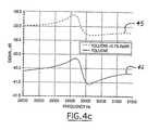
- FIG. 4 cillustrates a sample response of the representative circuit shown in FIG. 4 b
- FIGS. 5 a and 5 bare examples of traces comparing the frequency responses of the TSM resonator and the tuning fork resonator of the present invention, respectively;
- FIGS. 6 a and 6 bare examples of graphs illustrating the relationship between the viscosity density product and the equivalent serial resistance of the TSM resonator and the tuning fork resonator of the present invention, respectively;
- FIGS. 7 a and 7 bare examples of graphs illustrating the relationship between the dielectric constant and the equivalent parallel capacitance of the TSM resonator and the tuning fork resonator of the present invention, respectively;
- FIGS. 8 a and 8 bare examples of graphs illustrating the relationship between the molecular weight of a sample composition and the equivalent serial resistance of the TSM resonator and the tuning fork resonator of the present invention, respectively, in a polymerization reaction;
- FIGS. 9 a and 9 billustrate another embodiment of the invention using a resonator that is treated with a coating for targeting detection of specific chemicals
- FIGS. 10 a, 10 b and 10 cillustrate examples of different multiple resonator sensors of yet another embodiment of the present invention.
- the method and apparatus of the present inventionfocuses on using a mechanical resonator to generate and receive oscillations in a fluid composition for testing its characteristics in a combinatorial chemistry process or other process requiring analysis of the fluid composition's physical and/or chemical properties.
- the detailed descriptionfocuses on combinatorial chemistry and the measurement of a liquid composition's characteristics
- the inventioncan be used in any application requiring measurement of characteristics of a fluid composition, whether the fluid is in liquid or vapor form.
- the fluid compositionitself can be any type of fluid, such as a solution, a liquid containing suspended particulates, or, in some embodiments, even a vapor containing a particular chemical or a mixture of chemicals. It can also include a liquid composition undergoing a physical and/or chemical change (e.g. an increase in viscosity).
- TSM quartz resonators 10are used in the present invention for measuring various physical properties of fluid compositions, such as a liquid's viscosity, molecular weight, specific weight, etc., in a combinatorial chemistry setting or other liquid measurement application.
- TSM resonators 10usually have a flat, plate-like structure where a quartz crystal 12 is sandwiched in between two electrodes 14 .
- the userfirst generates a “library”, or large collection, of compounds in a liquid composition. Normally, each liquid composition is placed into its own sample well.
- a TSM resonator 10 connected to an input signal source (not shown)is placed into each liquid composition, and a variable frequency input signal is sent to each TSM resonator 10 , causing the TSM resonator 10 to oscillate.
- the input signal frequencyis swept over a predetermined range to generate a unique TSM resonator 10 response for each particular liquid. Because every compound has a different chemical structure and consequently different properties, the TSM resonator 10 response will be also be different for each compound.
- the TSM resonator responseis then processed to generated a visual trace of the liquid composition being tested. An example of traces generated by the TSM resonator 10 for multiple liquid compositions is shown in FIG. 5 a. Screening and analysis of each compound's properties can then be conducted by comparing the visual traces of each compound with a reference and/or with other compounds. In this type of application, the TSM resonator 10 serves both as the wave source and the receiver.
- acoustic wavesTwo types can be excited in liquids: compression waves (also called acoustic waves), which tend to radiate a large distance, on the order of hundreds of wavelengths, from the wave-generating source; and viscose shear waves, which decay almost completely only one wavelength away from the wave-generating source.
- compression wavesalso called acoustic waves
- viscose shear waveswhich decay almost completely only one wavelength away from the wave-generating source.
- acoustic wavesshould be kept to a minimum because they will create false readings when received by the resonator due to their long decay characteristics.
- the resonator oscillationcreates acoustic waves that radiate in all directions from the resonator, bounce off the sides of the sample well, and adversely affect the resonator response.
- the resonator responsewill not only reflect the properties of the liquid being measured, but also the effects of the acoustic waves reflecting from the walls of the sample well holding the liquid, thereby creating false readings.
- Using a sample well that is much greater than the acoustic wavelengthdoes minimize the negative effects of acoustic waves somewhat, but supplying thousands of sample wells having such large dimensions tends to be impractical.
- TSM resonators 10primarily generate viscose shear waves and are therefore a good choice for liquid property measurement in combinatorial chemistry applications because they do not generate acoustic waves that could reflect off the sides of the sample wells and generate false readings.
- the sample wells used with the TSM resonators 10can be kept relatively small, making it feasible to construct an array of sample wells for rapid, simultaneous testing of many liquids.
- the high stiffness of TSM resonators 10require them to be operated at relatively high frequencies, on the order of 8-10 MHz. This stiffness does not adversely affect measurement accuracy for many applications, though, making the TSM resonator an appropriate choice for measuring numerous liquid compositions.
- TSM resonators 10can be somewhat insensitive to the physical properties of certain liquids because the load provided by the surrounding liquid is less than the elasticity of the resonator. More particularly, the high operating frequencies of TSM resonators 10 make them a less desirable choice for measuring properties of certain liquid compositions, particularly high-molecular weight materials such as polymers. When high frequency waves are propagated through high molecular-weight liquids, the liquids tend to behave like gels because the rates at which such large molecules move correspond to frequencies that are less than that of the TSM resonator's oscillations. This causes the TSM resonator 10 to generate readings that sometimes do not reflect the properties at which the liquids will actually be used (most materials are used in applications where the low-frequency dynamic response is most relevant).
- the stiffness of the TSM resonator 10 and its resulting high operating frequenciescan make operation at lower frequencies rather difficult. Further, even when the TSM resonator 10 can accurately measure a liquid's properties, the differences in the visual traces associated with different compositions are relatively slight, making it difficult to differentiate between compositions having similar structures, as shown in FIG. 5 a.
- TSM resonators and other plate-type resonatorsmay not always be the best choice for measuring the electrical characteristics, such as the dielectric constant, of the liquid composition being measured.
- the cross-section of a TSM resonator 10has the same structure as a flat capacitor, resulting in relatively little coupling between the electric field of the resonator and the surrounding composition. While there can be enough electrical coupling between the resonator and the composition to measure the composition's electrical properties, a greater amount of electrical coupling is more desirable for increased measurement accuracy. Electrical coupling will be explained in greater detail below when comparing the electrical characteristics between the TSM resonator 10 and the tuning fork resonator 20 .
- FIGS. 1 a and 1 bshow a cross-section of a TSM resonator plate 10 and a tuning fork tine 22 , respectively.
- the tuning fork resonator 20is preferably made from a quartz crystal 24 and has two tines 22 , as represented in FIG. 2, each tine having the quartz crystal center 24 and at least one electrode 26 connected to the quartz crystal 24 .
- the tuning fork tines 22 in the preferred structurehave a square or rectangular cross-section such that the quartz crystal center 24 of each tine has four faces.
- the electrodes 26are then attached to each face of the quartz crystal center 24 , as shown in FIG. 1 b.
- the method and system of the present inventioncan use any type of tuning fork resonator, such as a trident (three-prong) tuning fork or tuning forks of different sizes, without departing from the spirit and scope of the invention.
- the cross-sectional views of the TSM resonator 10 and the tuning fork resonator 20 shown in FIGS. 1 a and 1 balso illustrate the relative differences between the electric coupling of each resonator with the surrounding liquid.
- the structure of the TSM resonator 10is very flat, making it close to a perfect capacitor when it is placed in the liquid to be measured.
- the quartz crystal 12 in the TSM resonator 10is sandwiched between two electrodes 14 , causing most of an electric field 16 to travel between the two electrodes through the quartz crystal 12 .
- each tuning fork tine 22allows much greater electrical coupling between the tine 22 and the surrounding liquid because the tuning fork tine's cross-sectional structure has a much different structure than a flat capacitor. Because the tuning fork tine 22 is submerged within the liquid being tested, an electric field 27 associated with each tine 22 does not concentrate in between the electrodes 24 or within the quartz crystal 24 , but instead interacts outside the tine 22 with the surrounding liquid. This increased electrical coupling allows the tuning fork 20 to measure accurately the electrical properties of the liquid as well as its physical properties, and it can measure both types of properties simultaneously if so desired.
- tuning fork resonator 20One unexpected result of the tuning fork resonator 20 is its ability to suppress the generation of acoustic waves in a liquid being tested, ensuring that the resonator's 20 physical response will be based only on the liquid's physical properties and not on acoustic wave interference or the shape of the sample well holding the liquid.
- TSM resonators 10minimize excitation of acoustic waves because it generates shear oscillations, which do not excite waves normal to the resonator's surface.
- the TSM resonator 10requires high frequency operation and is not suitable for many measurement applications, particularly those involving high-molecular weight liquids.
- tuning fork resonator 20used in the present invention virtually eliminates the effects of acoustic waves without having to increase the size of the sample wells to avoid wave reflection.
- Tuning fork resonators 20because of their shape and their orientation in the liquid being tested, contain velocity components normal to the vibrating surface. Thus, it was assumed in the art that tuning fork resonators were unsuitable for measuring liquid properties because they would generate acoustic waves causing false readings. In reality, however, tuning fork resonators 20 are very effective in suppressing the generation of acoustic waves for several reasons.
- the preferred size of the tuning fork resonator 20 used in the inventionis much smaller than the wavelength of the acoustic waves that are normally generated in a liquid, as much as one-tenth to one-hundredth the size.
- the tines 22 of the tuning fork resonator 20oscillate in opposite directions, each tine 22 acting as a separate potential acoustic wave generator. In other words, the tines 22 either move toward each other or away from each other. Because the tines 22 oscillate in opposite directions and opposite phases, however, the waves that end up being generated locally by each tine 22 tend to cancel each other out, resulting in virtually no acoustic wave generation from the tuning fork resonator 22 as a whole.
- FIG. 2A simplified diagram of one example of the inventive mechanical resonator 20 system is shown in FIG. 2 .
- the TSM resonator 10 described abovecan also be used for the same purpose.
- the tuning fork resonator 20is simply submerged in the liquid to be tested.
- a variable frequency input signalis then sent to the tuning fork resonator using any known means to oscillate the tuning fork, and the input signal frequency is swept over a predetermined range.
- the tuning fork resonator's responseis monitored and recorded.
- the tuning fork resonator 20is placed inside a well 26 containing a liquid to be tested.
- This liquidcan be one of many liquids for comparison and screening or it can simply be one liquid whose properties are to be analyzed independently. Further, if there are multiple liquids to be tested, they can be placed in an array and measured simultaneously with a plurality of tuning fork resonators to test many liquids in a given amount of time.
- the liquidcan also be a liquid that is undergoing a polymerization reaction or a liquid flowing through a conduit.
- the tuning fork resonator 20is preferably coupled with a network analyzer 28 , such as a Hewlett-Packard 8751A network analyzer, which sends a variable frequency input signal to the tuning fork resonator 20 to generate the resonator oscillations and to receive the resonator response at different frequencies.
- the resonator outputthen passes through a high impedance buffer 30 before being measured by a wide band receiver 32 .
- the inventionis not limited to this specific type of network analyzer, however; any other analyzer that generates and monitors the resonator's response over a selected frequency range can be used without departing from the scope of the invention.
- a sweep generator and AC voltmetercan be used in place of the network analyzer.
- FIGS. 4 a and 4 bAn equivalent circuit of the tuning fork resonator 20 and its associated measurement circuit is represented in FIGS. 4 a and 4 b .
- FIG. 4 arepresents an illustrative tuning fork resonator system that measures a liquid's viscosity and dielectric constant simultaneously
- FIG. 4 brepresents a tuning fork resonator system that can also measure a liquid's conductivity as well.
- the measurement circuitincludes a variable frequency input signal source 42
- the resonator equivalent circuit 43contains series capacitor Cs, resistor Rs, inductor L, and parallel capacitor Cp.
- the resonator equivalent circuit 43explicitly illustrates the fact that the quartz crystal 24 in the tuning fork resonator 20 acts like a capacitor Cp.
- the representative circuit 40also includes input capacitor Cin, input resistor Rin and an output buffer 44 .
- the representative circuit shown in FIG. 4 badds a parallel resistor Rp in parallel to capacitor Cp to illustrate a circuit that measures conductivity as well as dielectric constant and viscosity, preferably by comparing the equivalent resistance found in a given liquid with a known resistance found via calibration.
- Rprepresents the conductivity of the liquid being tested.
- the resistancecan be calibrated using a set of liquids having known conductivity and then used to measure the conductivity of a given liquid.
- FIG. 4 cshows a sample trace comparing the resonator response in pure toluene and in KaBr toluene solution.
- a liquid having greater conductivitytends to shift the resonator response upward on the graph, similar to liquids having higher dielectric constants. However, unlike liquids with higher dielectric constants, a liquid having greater conductivity will also cause the resonator response to level out somewhat in the frequency sweep, as can be seen in the upper trace 45 between 30 and 31.5 kHz. In the example shown in FIG. 4 c, the difference between the upper trace 45 and the lower trace 46 indicates that the equivalent resistance Rp caused by the additional KaBr in solution was about 8 mega-ohms.
- FIGS. 5 a-b, 6 a-b, 7 a-b and 8 a-bare examples demonstrating the effectiveness of the invention. These figures show some differences between the frequency responses, for various liquid compositions, of the plate-type TSM resonator 10 and the tuning fork resonator 20 .
- FIGS. 5 a, 6 a, 7 a and 8 aare examples using the TSM resonator 10
- FIGS. 5 b, 6 b, 7 b and 8 bare examples using the tuning fork resonator 20 .
- the experimental conditions for generating the example tuning fork resonator traces in FIGS. 5 b, 6 b, 7 b, and 8 bare described below.
- the experimental conditions for generating the comparative TSM resonator traces in FIGS. 5 a, 6 a, 7 a and 8 aare generally similar to, if not the same as, the conditions for the tuning fork resonator except for, if needed, minor modifications to accommodate the TSM resonator's particular geometry. Therefore, for simplicity and clarity, the TSM resonator's particular experimental conditions will not be described separately.
- the tuning fork resonator response in airwas measured as a reference.
- the actual testing processeswere conducted in a temperature-controlled laboratory set at around 20 degrees Centigrade. Once the liquid was delivered to the well, the tuning fork was placed in the well and the system was left alone to allow the temperature to stabilize. Alternatively, the tuning fork can be built into a wall portion or a bottom portion of the well with equally accurate results. The tuning fork was then oscillated using the network analyzer. The resonator response was recorded during each measurement and stored in a computer memory. The measured response curve was fitted to a model curve using an equivalent circuit, which provided specific values for the equivalent circuit components described above with respect to FIGS. 4 a and 4 b and the traces in FIGS. 6 a through 8 b.
- the resonatorwas kept in the well and pure solvent was poured inside the well to dissolve any polymer residue or coating in the well and on the tuning fork.
- the well and tuning forkwere blown dry using dry air, and the tuning fork response in air was measured again and compared with the initial tuning fork measurement to ensure that the tuning fork was completely clean; a clean tuning fork would give the same response as the initial tuning fork response.
- the tuning fork resonator 20has wider application than the TSM resonator 10 and is considered by the inventors to be the preferred embodiment for most measurement applications because of its sensitivity, availability and relatively low cost.
- the frequency sweep for the TSM resonator 10is in the 8 MHz range
- the frequency sweep for the tuning fork resonator 20 of the present inventionis in the 25-30 kHz range, several orders of magnitude less than the TSM resonator frequency sweep range.
- the operating frequency of the tuning fork resonator 20varies according to the resonator's geometry; more particularly, the resonance frequency of the tuning fork 20 depends on the ratio between the tine cross-sectional area and the tine's length. Theoretically, it is possible to construct a tuning fork resonator 20 of any length for a given frequency by changing the tuning fork's cross-sectional area to keep the ratio between the length and the cross-section constant. In practice, however, tuning fork resonators 20 are manufactured from quartz wafers having a few selected standard thicknesses.
- the cross-sectional area of the tuning fork 20tends to be limited based on the standard quartz wafer thicknesses, forcing the manufacturer to change the tuning fork's resonating frequency by changing the tine length.
- These manufacturing limitationsmust be taken into account when selecting a tuning fork resonator 20 that is small enough to fit in minimal-volume sample wells (because the chemicals used are quite expensive) and yet operates at a frequency low enough to prevent the tested liquids from acting like gels.
- the overall size of the tuning fork resonator 20is not as crucial, allowing greater flexibility in selecting the size and dimensions of the tuning fork resonator 20 . Selecting the actual tuning fork dimensions and designing a tuning fork resonator in view of manufacturing limitations are tasks that can be conducted by those of skill in the art after reviewing this specification.
- the solutions used as examples in FIGS. 5 a and 5 bhave somewhat similar structures and weights.
- the TSM resonator responses for each solutionshown in FIG. 5 a, create very similar traces in the same general range. Because the traces associated with the TSM resonator 10 overlap each other to such a great extent, it is difficult to isolate and compare the differences between the responses associated with each solution.
- the increased sensitivity of the tuning fork resonator 20causes small differences in the chemical structure to translate into significant differences in the resonator response. Because the traces generated by the tuning fork resonator 20 are so distinct and spaced apart, they are much easier to analyze and compare.
- Using a tuning fork resonator 20 to measure properties of liquidsalso results in greater linearity in the relationship between the square root of the product of the liquid's viscosity density and the equivalent serial resistance Rs (FIGS. 6 a and 6 b ) as well as in the relationship between the dielectric constant and the equivalent parallel capacitance Cp (FIGS. 7 a and 7 b ) compared to TSM resonators 10 .
- the relationship between the liquid viscosity and serial resistance for a tuning fork resonator 20is much more linear than that for the TSM resonator, as shown in FIG. 6 a.
- the relationship between the dielectric constant and the equivalent parallel capacitanceis more linear for a tuning fork resonator 20 , as shown in FIGS. 7 a and 7 b.
- This improved linear relationshipis primarily due to the relatively low frequencies at which the tuning fork resonator 20 operates; because many liquids exhibit different behavior at the operating frequencies required by the TSM resonator 10 , the TSM resonator 10 will tend not to generate testing results that agree with known data about the liquids'characteristics.
- FIGS. 8 a and 8 billustrate sample results from real-time monitoring of polymerization reactions by a TSM resonator and a tuning fork resonator, respectively.
- the graphsplot the equivalent resistance Rs of the resonators oscillating in 10 and 20 mg/ml polystyrene-toluene solutions versus the average molecular weight of polystyrene. As explained above, high molecular weight solutions often exhibit different physical characteristics, such as viscosity, at higher frequencies.
- the size and shape of the TSM resonator 10make the resonator suitable, but not as accurate, for real-time monitoring of polymerization reactions compared with the tuning fork resonator 20 .
- a high operating frequency TSM resonatoris not very sensitive in monitoring the molecular weight of the polystyrene solution used in the illustrated example.
- a tuning fork resonatorby contrast, has greater sensitivity to the molecular weight of the solution being measured, as shown in FIG. 8 b. This sensitivity and accuracy makes it possible, for many reactions, to estimate the amount of converted solution in the polymerization reaction and use the conversion data to estimate the average molecular weight of the polymer being produced.
- the resonatorcan also be treated with a “functionality” (a specialized coating) so that it is more sensitive to certain chemicals.
- the resonatormay also be treated with a general coating to protect the resonator from corrosion or other problems that could impede its performance.
- a representative diagram of an embodiment having a functionalized resonatoris shown in FIGS. 9 a and 9 b.
- FIGS. 9 a and 9 bas well as the following description focuses on coating or functionalizing a tuning fork resonator, any other mechanical resonator can also be used without departing from the scope of the invention.
- the tuning fork resonator 20can be coated with a selected material to change how the resonator 20 is affected by a fluid composition (which, as explained earlier, includes both liquid and vapor compositions).
- a fluid compositionwhich, as explained earlier, includes both liquid and vapor compositions.
- one optionis a general coating for providing the tuning fork resonator 20 with additional properties such as corrosion resistance, chemical resistance, electrical resistance, and the like.
- Another option, as noted above,is using a “functionality”, which coats the tines with materials that are designed for a specific application, such as proteins to allow the tuning fork resonator 20 to be used as a pH meter or receptors that attract specific substances in the fluid composition to detect the presence of those substances.
- the coating or functionalitycan be applied onto the tuning fork resonator 20 using any known method, such as spraying or dipping. Further, the specific material selected for the coating or functionality will depend on the specific application in which the tuning fork resonator 20 is to be used. J. Hlavay and G. G. Guilbault described various coating and functionalization methods and materials to adapt piezoelectric crystal detectors for specific applications in “Applications of the Piezoelectric Crystal Detector in Analytical Chemistry,” Analytical Chemistry, Vol. 49, No. 13, November 1977, p. 1890, incorporated herein by reference. For example, applying different inorganic functionalities to the tuning fork resonator 20 allows the resonator to detect organophosphorous compounds and pesticides.
- FIGS. 9 a and 9 bAn example of a tuning fork resonator that has undergone a functionalization treatment is illustrated in FIGS. 9 a and 9 b.
- FIG. 9 arepresents a tuning fork tine 22 that has been treated by absorbing, coating, or otherwise surrounding the tine 22 with a functionality designed to change the tuning fork's resonance frequency after being exposed to a selected target chemical.
- the tuning fork tine 22is covered with receptor molecules 90 , represented in FIGS. 9 a and 9 b by Y-shaped members, designed to bond with specific target molecules.
- the resonance frequency and the damping of the tuning fork resonatordepends on the effective mass of the tine 22 and the amount of “drag” of the tine 22 within the fluid, any change in the tine's mass or the amount of drag will change the tuning fork's resonance response. More specifically, the resonance frequency of the tuning fork resonator is proportional to the square root of the inverse of the tuning fork's mass. An increase in the tuning fork's mass will therefore reduce the tuning fork's resonance frequency.
- This mass-frequency relationshipis used to detect the presence of a specific target chemical in a fluid composition in this example.
- the receptors 90 on the tuning fork tine 22will chemically bond with molecules of the target chemical 92 , as shown in FIG. 9 b.
- the resonance frequency of the tuning fork resonatorwill consequently decrease because of the increased mass and the additional drag created by the additional molecules 92 attached to the tuning fork tines 22 via the receptor molecules 90 .
- only the fluid compositions containing the target chemicalwill cause the tuning fork's resonance frequency to change.
- the tuning fork tines 22can be functionalized with a material that physically changes when exposed to molecules of a selected chemical such that the material changes the mechanical drag on the tuning fork tine 22 when it is exposed to the selected chemical.
- adding a hydrophobic or hydrophilic functionality to the tuning fork tine 22allows the tine 22 to attract or repel selected substances in the medium being analyzed, changing the mass or effective mass of the tuning fork and thereby changing its resonance frequency.
- multiple mechanical resonatorscan be attached together in a single sensor to measure a wider range of responses for a given fluid composition, as shown in FIGS. 10 a, 10 b and 10 c.
- the multiple resonator sensorcan be fabricated from a single quartz piece such that all of the resonators are attached together by a common base, as shown in the figures.
- the multi-resonator sensorcould also be attached to multiple frequency generating circuits, such as multiple network analyzers 28 , to measure properties of the fluid compositions over multiple frequency sweeps so that the generated data can be correlated to obtain additional information about the liquid compositions.
- FIGS. 10 a, 10 b and 10 cshow specific examples of possible multi-resonator configurations, but those of skill in the art would understand that sensors having any combination of resonators can be constructed without departing from the scope of the invention.
- FIG. 10 aillustrates one possible sensor 100 configuration containing both a tuning fork resonator 102 and a TSM resonator 104 .
- This type of sensor 100can be used to, for example, measure the mechanical and electrical properties of very thick liquids such as polymer resins and epoxies.
- This sensor 100can also be used to monitor a material as it polymerizes and hardens.
- the sensor 100can be placed in a liquid composition containing urethane rubber in its diluted state so that the tuning fork 102 is used initially to measure both the composition's density viscosity product and its dielectric constant. As the rubber changes to a gel and finally to a solid, the sensor 100 can switch to using the TSM resonator 104 to measure the rubber's mechanical properties, leaving the tuning fork resonator 102 to operate as a dielectric sensor only.
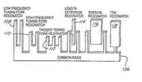
- a sensor 106 for observing a fluid composition over a wide frequency rangeis shown in FIG. 10 b.
- High polydispersity polymer solutionsare ideally measured over a wide frequency spectrum, but most resonators have optimum performance within a relatively limited frequency range.
- By combining different resonators having different resonance frequencies and different response characteristicsit is possible to obtain a more complete spectrum of resonator responses for analyzing the fluid's characteristics under many different conditions. For example, due to the wide spectrum of polydisperse solution relaxation times, it is generally predicted that high molecular weight compositions will react at lower frequencies than lighter molecular weight compositions.
- By changing the temperature, observing the frequency response of different resonators, and correlating the different resonator responsesit is possible to obtain a more accurate picture of a composition's relaxation spectrum than from a single resonator.
- the resonators in the multi-resonator sensor 106can also include a trident tuning fork resonator 112 , a length extension resonator 114 , a torsion resonator 116 , and a TSM resonator 118 , membrane oscillators, bimorphs, unimorphs, and various surface acoustic wave devices, as well as any combination thereof, or even a single resonator structure than can operate in multiple mechanical modes (e.g. compression mode, axial mode, torsion mode).
- a trident tuning fork resonator 112e.g., a length extension resonator 114 , a torsion resonator 116 , and a TSM resonator 118 , membrane oscillators, bimorphs, unimorphs, and various surface acoustic wave devices, as well as any combination thereof, or even a single resonator structure than can operate in multiple mechanical modes (e.g
- multiple resonators having the same structure but different coatings and/or functionalitiescan be incorporated into one sensor 120 , as shown in FIG. 10 c.
- a plurality of tuning fork resonators 122 , 124 , 126have the same structure but have different functionalities, each functionality designed to, for example, bond with a different target molecule.
- the high sensitivity of the tuning fork resonators 122 , 124 , 126makes them particularly suitable for “artificial noses” that can detect the presence of an environmentally-offending molecule, such as hydrogen sulfide or nitrous oxide, in industrial emissions.
- one tuning fork resonator 122can, for example, be functionalized with a material designed to bond with hydrogen sulfide while another resonator 124 can be functionalized with a material designed to bond with nitrous oxide.
- the presence of either one of these molecules in the fluid composition being testedwill cause the corresponding tuning fork resonator 122 , 124 to change its resonance frequency, as explained with respect to FIGS. 9 a and 9 b.
- the tuning fork resonators 122 , 124 , 126can also be functionalized with a polymer layer or other selective absorbing layer to detect the presence of specific molecules in a vapor. Because the tuning fork resonators 122 , 124 , 126 are highly sensitive to the dielectric constant of the surrounding fluid, the tuning fork resonators 122 , 124 , 126 can easily detect changes in the dielectric constant of the fluid and recognize a set of solvents with different dielectric constants in the fluid. This information, combined with other observable parameters, makes tuning fork resonators particularly adaptable for use in artificial noses.
- the method and system of the present inventionhas been described above in the combinatorial chemistry context, but it is not limited to such an application. Because the resonators in the method and system of the present invention have high sensitivities and quick response times, it can be also be used for in-line monitoring of fluid compositions flowing through conduits or pipelines.
- the inventioncan be used in a feedback system to monitor properties of liquids flowing through a gas or oil pipeline to monitor and control the concentration of additives in the gas or oil, or to detect the presence of impurities in water flowing through a water pipe. The additives or impurities will change the physical and electrical characteristics of the liquid flowing through the conduit.
- a functionalized tuning fork resonator 20can further detect the presence of a specific chemical in a fluid composition, whether it is a liquid or a vapor, and can be used to monitor the presence of, for example, a known chemical pollutant in a smokestack.
- the circuitry and system used to generate the visual traces from the resonator's responsecan be the same as described above or be any other equivalent resonator analysis system.
- TSM resonatorsany other mechanical resonators exhibiting similar characteristics can be used.
- Tridents, cantilevers, torsion bars, bimorphs, and/or membrane resonatorscan be substituted for the TSM resonator or tuning fork resonator without departing from the scope of the claimed invention.
Landscapes
- Physics & Mathematics (AREA)
- General Physics & Mathematics (AREA)
- Immunology (AREA)
- Pathology (AREA)
- Chemical & Material Sciences (AREA)
- Analytical Chemistry (AREA)
- Biochemistry (AREA)
- General Health & Medical Sciences (AREA)
- Health & Medical Sciences (AREA)
- Life Sciences & Earth Sciences (AREA)
- Engineering & Computer Science (AREA)
- Acoustics & Sound (AREA)
- Signal Processing (AREA)
- Multimedia (AREA)
- Investigating Or Analyzing Materials By The Use Of Electric Means (AREA)
- Investigating Or Analyzing Materials By The Use Of Ultrasonic Waves (AREA)
Abstract
Description
Claims (14)
Priority Applications (5)
| Application Number | Priority Date | Filing Date | Title |
|---|---|---|---|
| US09/800,819US6494079B1 (en) | 2001-03-07 | 2001-03-07 | Method and apparatus for characterizing materials by using a mechanical resonator |
| US10/201,181US7334452B2 (en) | 1997-10-08 | 2002-07-23 | Method for characterizing materials by using a mechanical resonator |
| US10/266,047US6904786B2 (en) | 1997-10-08 | 2002-10-07 | Method and apparatus for characterizing materials by using a mechanical resonator |
| US10/685,962US6957565B2 (en) | 1997-10-08 | 2003-10-15 | Method and apparatus for characterizing materials by using a mechanical resonator |
| US10/686,444US7073370B2 (en) | 1997-10-08 | 2003-10-15 | Method and apparatus for characterizing materials by using a mechanical resonator |
Applications Claiming Priority (1)
| Application Number | Priority Date | Filing Date | Title |
|---|---|---|---|
| US09/800,819US6494079B1 (en) | 2001-03-07 | 2001-03-07 | Method and apparatus for characterizing materials by using a mechanical resonator |
Related Parent Applications (1)
| Application Number | Title | Priority Date | Filing Date |
|---|---|---|---|
| US09/133,171DivisionUS6393895B1 (en) | 1997-10-08 | 1998-08-12 | Method and apparatus for characterizing materials by using a mechanical resonator |
Related Child Applications (2)
| Application Number | Title | Priority Date | Filing Date |
|---|---|---|---|
| US10/201,181ContinuationUS7334452B2 (en) | 1997-10-08 | 2002-07-23 | Method for characterizing materials by using a mechanical resonator |
| US10/266,047ContinuationUS6904786B2 (en) | 1997-10-08 | 2002-10-07 | Method and apparatus for characterizing materials by using a mechanical resonator |
Publications (1)
| Publication Number | Publication Date |
|---|---|
| US6494079B1true US6494079B1 (en) | 2002-12-17 |
Family
ID=25179453
Family Applications (5)
| Application Number | Title | Priority Date | Filing Date |
|---|---|---|---|
| US09/800,819Expired - LifetimeUS6494079B1 (en) | 1997-10-08 | 2001-03-07 | Method and apparatus for characterizing materials by using a mechanical resonator |
| US10/201,181Expired - Fee RelatedUS7334452B2 (en) | 1997-10-08 | 2002-07-23 | Method for characterizing materials by using a mechanical resonator |
| US10/266,047Expired - Fee RelatedUS6904786B2 (en) | 1997-10-08 | 2002-10-07 | Method and apparatus for characterizing materials by using a mechanical resonator |
| US10/685,962Expired - LifetimeUS6957565B2 (en) | 1997-10-08 | 2003-10-15 | Method and apparatus for characterizing materials by using a mechanical resonator |
| US10/686,444Expired - Fee RelatedUS7073370B2 (en) | 1997-10-08 | 2003-10-15 | Method and apparatus for characterizing materials by using a mechanical resonator |
Family Applications After (4)
| Application Number | Title | Priority Date | Filing Date |
|---|---|---|---|
| US10/201,181Expired - Fee RelatedUS7334452B2 (en) | 1997-10-08 | 2002-07-23 | Method for characterizing materials by using a mechanical resonator |
| US10/266,047Expired - Fee RelatedUS6904786B2 (en) | 1997-10-08 | 2002-10-07 | Method and apparatus for characterizing materials by using a mechanical resonator |
| US10/685,962Expired - LifetimeUS6957565B2 (en) | 1997-10-08 | 2003-10-15 | Method and apparatus for characterizing materials by using a mechanical resonator |
| US10/686,444Expired - Fee RelatedUS7073370B2 (en) | 1997-10-08 | 2003-10-15 | Method and apparatus for characterizing materials by using a mechanical resonator |
Country Status (1)
| Country | Link |
|---|---|
| US (5) | US6494079B1 (en) |
Cited By (53)
| Publication number | Priority date | Publication date | Assignee | Title |
|---|---|---|---|---|
| US20020178805A1 (en)* | 2001-05-15 | 2002-12-05 | Baker Hughes Inc. | Method and apparatus for downhole fluid characterization using flexural mechanical resonators |
| US20030000291A1 (en)* | 2001-06-06 | 2003-01-02 | Symyx Technologies, Inc. | Flow detectors having mechanical oscillators, and use thereof in flow characterization systems |
| US20030101822A1 (en)* | 2000-03-27 | 2003-06-05 | Eric Atherton | Sensor apparatus |
| US20030218467A1 (en)* | 2002-05-24 | 2003-11-27 | Symyx Technologies, Inc. | High throughput microbalance and methods of using same |
| US20040074302A1 (en)* | 1997-10-08 | 2004-04-22 | Symyx Technologies, Inc. | Method and apparatus for characterizing materials by using a mechanical resonator |
| US20040107055A1 (en)* | 2002-10-18 | 2004-06-03 | Symyx Technologies, Inc. | Application specific integrated circuitry for controlling analysis of a fluid |
| US20040150428A1 (en)* | 2002-12-26 | 2004-08-05 | Atsushi Itoh | Analysis method using piezoelectric resonator |
| US20040236512A1 (en)* | 2001-05-15 | 2004-11-25 | Baker Hughes Inc. | Method and apparatus for chemometric estimations of fluid density, viscosity, dielectric constant, and resistivity from mechanical resonator data |
| US20050016276A1 (en)* | 2003-06-06 | 2005-01-27 | Palo Alto Sensor Technology Innovation | Frequency encoding of resonant mass sensors |
| US20050054116A1 (en)* | 2003-09-05 | 2005-03-10 | Potyrailo Radislav A. | Method of manufacturing and evaluating sensor coatings and the sensors derived therefrom |
| WO2004086027A3 (en)* | 2003-03-21 | 2005-06-09 | Symyx Technologies Inc | Mechanical resonator |
| US20050209796A1 (en)* | 2003-03-21 | 2005-09-22 | Symyx Technologies, Inc. | Integrated circuitry for controlling analysis of a fluid |
| US20050241373A1 (en)* | 2003-07-21 | 2005-11-03 | Aria Analytics, Inc. | Method and apparatus for determination of food quality and authenticity |
| US20050247119A1 (en)* | 2001-05-15 | 2005-11-10 | Baker Hughes Incorporated | Method and apparatus for downhole fluid characterization using flexural mechanical resonators |
| US20050262926A1 (en)* | 2003-07-21 | 2005-12-01 | Aria Analytics, Inc. | Method and apparatus for determination of medical diagnostics utilizing biological fluids |
| US20050262944A1 (en)* | 2004-04-21 | 2005-12-01 | Symyx Technologies, Inc. | Flexural resonator sensing device and method |
| US7043969B2 (en) | 2002-10-18 | 2006-05-16 | Symyx Technologies, Inc. | Machine fluid sensor and method |
| US20060137873A1 (en)* | 2004-12-23 | 2006-06-29 | Derek Caudwell | Apparatus and method for formation evaluation |
| US20060186897A1 (en)* | 2005-02-18 | 2006-08-24 | Markus Niemann | Method and device for detecting two parameters of a fluid |
| JP2006520906A (en)* | 2003-03-21 | 2006-09-14 | サイミックス テクノロジーズ, インコーポレイテッド | Application specific integrated circuits for fluid analysis control |
| US20070017291A1 (en)* | 2005-04-01 | 2007-01-25 | Symyx Technologies, Inc. | Monitoring and controlling unit operations |
| US7194902B1 (en) | 2004-12-23 | 2007-03-27 | Schlumberger Technology Corporation | Apparatus and method for formation evaluation |
| US20070068493A1 (en)* | 2005-09-22 | 2007-03-29 | Igor Pavlovsky | Hydrogen sensor |
| EP1804048A1 (en)* | 2005-12-30 | 2007-07-04 | Services Pétroliers Schlumberger | A density and viscosity sensor |
| US7260980B2 (en) | 2003-03-11 | 2007-08-28 | Adams Jesse D | Liquid cell and passivated probe for atomic force microscopy and chemical sensing |
| US7272525B2 (en) | 2004-04-21 | 2007-09-18 | Visyx Technologies, Inc. | Portable fluid sensing device and method |
| US20070240491A1 (en)* | 2003-06-03 | 2007-10-18 | Nano-Proprietary, Inc. | Hydrogen Sensor |
| US20070251296A1 (en)* | 2004-08-12 | 2007-11-01 | Baker Hughes Incorporated | Method and apparatus for downhole detection of co2 and h2s using resonators coated with co2 and h2s sorbents |
| US7350367B2 (en) | 2002-10-18 | 2008-04-01 | Visyx Technologies, Inc. | Environmental control system fluid sensing system and method |
| US20080215245A1 (en)* | 2007-01-19 | 2008-09-04 | Baker Hughes Incorporated | System and method for determining producibility of a formation using flexural mechanical resonator measurements |
| US7521257B2 (en) | 2003-02-11 | 2009-04-21 | The Board Of Regents Of The Nevada System Of Higher Education On Behalf Of The University Of Nevada, Reno | Chemical sensor with oscillating cantilevered probe and mechanical stop |
| US20090100925A1 (en)* | 2006-10-27 | 2009-04-23 | Baker Hughes Incorporated | System and method for coating flexural mechanical resonators |
| DE102007053221A1 (en)* | 2007-11-06 | 2009-05-07 | Endress + Hauser Gmbh + Co. Kg | Method for determining and / or monitoring the growth of a biological substance in a medium |
| US20090133474A1 (en)* | 2003-06-03 | 2009-05-28 | Nano-Proprietary, Inc. | Method and apparatus for sensing hydrogen gas |
| US7634937B2 (en) | 2005-07-01 | 2009-12-22 | Symyx Solutions, Inc. | Systems and methods for monitoring solids using mechanical resonator |
| US20100005853A1 (en)* | 2005-08-03 | 2010-01-14 | Nano-Proprietary, Inc. | Continuous Range Hydrogen Sensor |
| US7694346B2 (en) | 2004-10-01 | 2010-04-06 | Board Of Regents Of The Nevada System Of Higher Education On Behalf Of The University Of Nevada | Cantilevered probe detector with piezoelectric element |
| US20100107735A1 (en)* | 2005-09-22 | 2010-05-06 | Igor Pavlovsky | Gas Sensor |
| US7721590B2 (en) | 2003-03-21 | 2010-05-25 | MEAS France | Resonator sensor assembly |
| US8409875B2 (en) | 2010-10-20 | 2013-04-02 | Rapid Diagnostek, Inc. | Measurement of binding kinetics with a resonating sensor |
| US8524501B2 (en) | 2003-10-17 | 2013-09-03 | Board Of Regents Of The Nevada System Of Higher Education | Self-sensing array of microcantilevers for chemical detection |
| WO2014066433A1 (en)* | 2012-10-22 | 2014-05-01 | Goodbread Joseph H | Method and device for measuring fluid properties |
| US8878548B2 (en) | 2010-06-11 | 2014-11-04 | Baker Hughes Incorporated | Method for treating and sealing piezoelectric tuning forks |
| US9752911B2 (en) | 2014-12-29 | 2017-09-05 | Concentric Meter Corporation | Fluid parameter sensor and meter |
| US9995666B2 (en) | 2012-10-22 | 2018-06-12 | Rheonics Gmbh | Resonant sensors for fluid properties measurement |
| US9995715B2 (en) | 2014-04-13 | 2018-06-12 | Rheonics Gmbh | Electromagnetic transducer for exciting and sensing vibrations of resonant structures |
| US10107784B2 (en) | 2014-12-29 | 2018-10-23 | Concentric Meter Corporation | Electromagnetic transducer |
| US10126266B2 (en) | 2014-12-29 | 2018-11-13 | Concentric Meter Corporation | Fluid parameter sensor and meter |
| US10281423B1 (en)* | 2017-11-14 | 2019-05-07 | United Arab Emirates University | Fuel quality sensor |
| RU2722975C1 (en)* | 2019-10-08 | 2020-06-05 | Федеральное государственное бюджетное учреждение науки Институт физической химии и электрохимии им. А.Н. Фрумкина РАН (ИФХЭ РАН) | Piezoelectric resonance sensor of substances microconcentration |
| US11360012B2 (en)* | 2017-12-19 | 2022-06-14 | Endress+Hauser SE+Co. KG | Vibronic sensor |
| US11768178B2 (en) | 2020-02-28 | 2023-09-26 | Baker Hughes Oilfield Operations Llc | Embedded electrode tuning fork |
| US11781961B1 (en)* | 2020-03-26 | 2023-10-10 | Rheonics Gmbh | Method and device for monitoring transformation processes of fluids |
Families Citing this family (81)
| Publication number | Priority date | Publication date | Assignee | Title |
|---|---|---|---|---|
| US7075347B2 (en)* | 2000-08-10 | 2006-07-11 | University Of Southern California | Multiphase resonant pulse generators |
| EP1423685B1 (en)* | 2001-06-20 | 2011-08-24 | M.S. Tech Ltd. | Array of piezoelectric resonators for the detection of trace amounts of a substance |
| US7148683B2 (en) | 2001-10-25 | 2006-12-12 | Intematix Corporation | Detection with evanescent wave probe |
| US20030101819A1 (en)* | 2001-12-04 | 2003-06-05 | Mutz Mitchell W. | Acoustic assessment of fluids in a plurality of reservoirs |
| EP1517140A3 (en)* | 2003-03-19 | 2005-04-06 | TF Instruments GmbH | Method and device for diagnostic investigation of biological samples |
| EP1664731B1 (en)* | 2003-03-21 | 2012-02-22 | MEAS France | Resonator sensor assembly |
| EP1646864B1 (en) | 2003-07-18 | 2018-11-07 | Rosemount Inc. | Process diagnostics |
| US20050095717A1 (en)* | 2003-10-31 | 2005-05-05 | Wollenberg Robert H. | High throughput screening methods for lubricating oil compositions |
| US20050095714A1 (en) | 2003-10-31 | 2005-05-05 | Wollenberg Robert H. | High throughput preparation of lubricating oil compositions for combinatorial libraries |
| US7579192B2 (en) | 2003-10-31 | 2009-08-25 | Chevron Oronite Company Llc | High throughput screening methods for lubricating oil compositions |
| US7069203B2 (en)* | 2003-10-31 | 2006-06-27 | Chevron Oronite Company Llc | Method and system of product development process for chemical compositions using high volume modeling |
| US7150182B2 (en)* | 2003-10-31 | 2006-12-19 | Chevron Oronite Company, Llc | High throughput screening methods for lubricating oil compositions |
| US7462490B2 (en) | 2003-10-31 | 2008-12-09 | Chevron Oronite Company Llc | Combinatorial lubricating oil composition libraries |
| US20090288479A1 (en)* | 2003-11-17 | 2009-11-26 | Woody Shane C | Standing wave fluidic and biological tools |
| EP1695046B1 (en)* | 2003-12-18 | 2011-10-12 | Endress + Hauser GmbH + Co. KG | Method and device for producing a measuring device for determining and/or monitoring a process variable, and corresponding measuring device |
| US7985592B2 (en)* | 2004-02-13 | 2011-07-26 | Chevron Oronite Company Llc | High throughput screening methods for lubricating oil compositions |
| US7306948B2 (en)* | 2004-02-13 | 2007-12-11 | Chevron Oronite Company Llc | High throughput screening methods for lubricating oil compositions |
| US8249816B2 (en)* | 2004-02-13 | 2012-08-21 | Chevron Oronite Company, Llc | High throughput screening methods for fuel compositions |
| US7137289B2 (en) | 2004-02-13 | 2006-11-21 | Chevron Oronite Company, Llc | High throughput screening methods for lubricating oil compositions |
| US8215170B2 (en)* | 2004-05-10 | 2012-07-10 | Arizona Board Of Regents | Chemical and biological sensing using tuning forks |
| US7866211B2 (en)* | 2004-07-16 | 2011-01-11 | Rosemount Inc. | Fouling and corrosion detector for process control industries |
| DE202004017677U1 (en)* | 2004-11-15 | 2005-01-05 | Elektromanufaktur Zangenstein Hanauer Gmbh & Co. Kgaa | Apparatus for detecting a conductance of a fluid |
| JP2006260090A (en)* | 2005-03-16 | 2006-09-28 | Fuji Xerox Co Ltd | Sheet, display medium unit, sheet attachment unit and sheet detachment unit |
| DE102005012453A1 (en)* | 2005-03-18 | 2006-09-21 | Robert Bosch Gmbh | Method and device for measuring the viscosity of non-Newtonian fluids, in particular engine fuels |
| US8794062B2 (en)* | 2005-08-01 | 2014-08-05 | Baker Hughes Incorporated | Early kick detection in an oil and gas well |
| US9109433B2 (en) | 2005-08-01 | 2015-08-18 | Baker Hughes Incorporated | Early kick detection in an oil and gas well |
| US7614302B2 (en)* | 2005-08-01 | 2009-11-10 | Baker Hughes Incorporated | Acoustic fluid analysis method |
| US7523640B2 (en)* | 2005-08-01 | 2009-04-28 | Baker Hughes Incorporated | Acoustic fluid analyzer |
| US7148611B1 (en)* | 2005-10-11 | 2006-12-12 | Honeywell International Inc. | Multiple function bulk acoustic wave liquid property sensor |
| US7313945B2 (en)* | 2005-10-31 | 2008-01-01 | Hewlett-Packard Development Company, L.P. | Cantilevers for sensing fluid properties |
| US7647965B2 (en)* | 2005-10-31 | 2010-01-19 | Baker Hughes Incorporated | Method and apparatus for insulating a resonator downhole |
| US7694734B2 (en)* | 2005-10-31 | 2010-04-13 | Baker Hughes Incorporated | Method and apparatus for insulating a resonator downhole |
| US20070137287A1 (en)* | 2005-12-16 | 2007-06-21 | Honeywell International Inc. | Acoustic wave particulate sensor |
| US7681449B2 (en)* | 2006-02-28 | 2010-03-23 | Exxonmobil Research And Engineering Company | Metal loss rate sensor and measurement using a mechanical oscillator |
| US7555940B2 (en)* | 2006-07-25 | 2009-07-07 | Veeco Instruments, Inc. | Cantilever free-decay measurement system with coherent averaging |
| US10018613B2 (en)* | 2006-11-16 | 2018-07-10 | General Electric Company | Sensing system and method for analyzing a fluid at an industrial site |
| US10539524B2 (en)* | 2006-11-16 | 2020-01-21 | General Electric Company | Resonant sensing system and method for monitoring properties of an industrial fluid |
| US8050875B2 (en)* | 2006-12-26 | 2011-11-01 | Rosemount Inc. | Steam trap monitoring |
| US8845968B2 (en)* | 2006-12-28 | 2014-09-30 | Highland Biosciences Limited | Biosensor |
| EP1950550A1 (en)* | 2007-01-25 | 2008-07-30 | Flamac | Method and apparatus for measuring viscosity and surface tension |
| WO2008112631A1 (en)* | 2007-03-09 | 2008-09-18 | The Board Of Regents Of The University Of Oklahoma | Test cell for applying a shear stress to a test specimen |
| US20100275689A1 (en)* | 2007-06-15 | 2010-11-04 | Exxonmobil Research And Engineering Company | Tuning Fork Oscillator Activated or Deactivated by a Predetermined Condition |
| US7721605B2 (en)* | 2007-06-15 | 2010-05-25 | Exxonmobil Research And Engineering Company | Mechanical oscillator activated or deactivated by a predetermined condition |
| GB0716542D0 (en)* | 2007-08-24 | 2007-10-03 | Highland Biosciences Ltd | Endotoxin biosensor |
| RU2380662C2 (en)* | 2007-08-24 | 2010-01-27 | Государственное образовательное учреждение высшего профессионального образования "Казанский государственный университет им. В.И. Ульянова-Ленина" | Device for investigating oscillatory phenomena and method of using said device |
| US20100086735A1 (en)* | 2008-10-03 | 2010-04-08 | The United States Of America As Represented By The Secretary Of The Navy | Patterned Functionalization of Nanomechanical Resonators for Chemical Sensing |
| US8217667B2 (en)* | 2009-01-16 | 2012-07-10 | Hill-Rom Services, Inc. | Method and apparatus for piezoelectric sensor status assessment |
| US8676543B2 (en)* | 2009-06-23 | 2014-03-18 | Exxonmobil Research And Engineering Company | Determining the resonance parameters for mechanical oscillators |
| EE05570B1 (en)* | 2009-08-12 | 2012-08-15 | Tartu Ülikool | Method and apparatus for measuring the concentration and the viscosity and surface tension of chemical and biological agents |
| DE102009029002B3 (en)* | 2009-08-28 | 2011-01-27 | Fraunhofer-Gesellschaft zur Förderung der angewandten Forschung e.V. | Photoacoustic sensor and method for its production and use |
| US9140667B2 (en)* | 2010-08-15 | 2015-09-22 | Vlad Novotny | Chemical and biomedical NanoSensors |
| US20120085161A1 (en)* | 2010-10-07 | 2012-04-12 | Baker Hughes Incorporated | Torsionally vibrating viscosity and density sensor for downhole applications |
| FR2971336B1 (en)* | 2011-02-08 | 2013-03-01 | Commissariat Energie Atomique | METHOD FOR DETECTING AND IDENTIFYING AN ANALYTE PRESENT IN A GASEOUS MEDIUM |
| US8511165B2 (en)* | 2011-03-24 | 2013-08-20 | Borja Lopez Jauregui | Electromagnetic acoustic transducer (EMAT) combined with piezoelectric transducer (PZT) for dual mode ultrasonic inspection |
| US9366133B2 (en) | 2012-02-21 | 2016-06-14 | Baker Hughes Incorporated | Acoustic standoff and mud velocity using a stepped transmitter |
| EP2650668A1 (en)* | 2012-04-12 | 2013-10-16 | Openfield | Density and viscosity sensor and measuring method |
| US10641412B2 (en) | 2012-09-28 | 2020-05-05 | Rosemount Inc. | Steam trap monitor with diagnostics |
| DE102012222487B4 (en)* | 2012-12-06 | 2015-03-12 | Robert Bosch Gmbh | Measuring method and apparatus for characterizing an adhesive |
| CN105051517A (en)* | 2013-04-03 | 2015-11-11 | 高准公司 | Vibration sensor and method |
| ITTO20130280A1 (en) | 2013-04-08 | 2014-10-09 | Start Italiana S P A | MAGNETOSTRITIVE LEVEL PROBE WITH INTEGRATED QUALITY SENSOR. |
| US10502677B2 (en)* | 2013-10-14 | 2019-12-10 | Exxonmobil Research And Engineering Company | Detection of corrosion rates in processing pipes and vessels |
| US10444133B2 (en) | 2015-03-06 | 2019-10-15 | National Institute For Materials Science | Molecular weight measurement method and molecular weight measurement apparatus |
| JP2018517914A (en)* | 2015-04-17 | 2018-07-05 | レオニクス ゲゼルシャフト ミット ベシュレンクテル ハフツングRheonics GmbH | Corrosion time profile measuring device |
| US20160356731A1 (en)* | 2015-06-05 | 2016-12-08 | Probe Holdings, Inc. | Thermal conductivity quartz transducer with waste-heat management system |
| CN107849916B (en) | 2015-08-07 | 2021-07-06 | 沙特阿拉伯石油公司 | Method and apparatus for measuring fluid properties using electromechanical resonators |
| US10291199B2 (en) | 2015-09-04 | 2019-05-14 | Ut-Battelle, Llc | Direct write sensors |
| KR101820101B1 (en)* | 2016-06-30 | 2018-01-18 | 서강대학교산학협력단 | Measuring apparatus and micro-tube manufacturing method in the same |
| US11333015B2 (en) | 2016-08-04 | 2022-05-17 | Saudi Arabian Oil Company | Method for capacitive cancellation of tuning fork for fluid property measurements |
| US11641168B2 (en)* | 2017-07-17 | 2023-05-02 | Georgia Tech Research Corporation | Parametric resonator for electrical transduction |
| GB2568946A (en)* | 2017-12-01 | 2019-06-05 | Hydramotion Ltd | Fluid property measurement by reflection of vibrational waves |
| US11378708B2 (en) | 2017-12-22 | 2022-07-05 | Baker Hughes, A Ge Company, Llc | Downhole fluid density and viscosity sensor based on ultrasonic plate waves |
| US11187636B1 (en)* | 2018-01-26 | 2021-11-30 | Kelvin Innovations LLC | Dielectrostriction measurement with electrical excitation frequency sweep method and rheo-dielectric coefficient for process monitoring, quality examination, and material characterization |
| CN108593763B (en)* | 2018-03-26 | 2021-03-30 | 山东大学 | Real-time detection device for multi-component gas based on quartz tuning fork frequency division demodulation |
| WO2020122901A1 (en)* | 2018-12-12 | 2020-06-18 | Micro Motion, Inc. | Planar vibratory viscometer, viscometer member, and related method |
| US20220011209A1 (en)* | 2018-12-12 | 2022-01-13 | Micro Motion, Inc. | Planar vibratory densitometer, densitometer member, and related method |
| US11035789B2 (en)* | 2019-04-03 | 2021-06-15 | Picomole Inc. | Cavity ring-down spectroscopy system and method of modulating a light beam therein |
| CN110132406B (en)* | 2019-06-04 | 2021-03-23 | 中车工业研究院有限公司 | Permanent magnet direct-drive electric locomotive coupler vibration detection method and system |
| KR20240108584A (en)* | 2019-08-20 | 2024-07-09 | 마이크로 모우션, 인코포레이티드 | Stabilized mode splitting fin sensor |
| US11169117B2 (en) | 2019-09-30 | 2021-11-09 | Afton Chemical Corporation | Methods to analyze hydrocarbon solutions |
| KR102853644B1 (en)* | 2019-12-27 | 2025-09-02 | 후지필름 가부시키가이샤 | Management method, measurement method, measuring device, crystal oscillator sensor, and, set |
| JP2024525364A (en) | 2021-06-29 | 2024-07-12 | ドナルドソン カンパニー,インコーポレイティド | Fluid condition sensing system and method |
Citations (51)
| Publication number | Priority date | Publication date | Assignee | Title |
|---|---|---|---|---|
| US3622968A (en) | 1969-05-15 | 1971-11-23 | Amoco Prod Co | Elastic-wave holography using reflections |
| US3718032A (en) | 1970-09-18 | 1973-02-27 | Hoffmann La Roche | Ultrasonic visualization |
| US3778757A (en) | 1972-09-01 | 1973-12-11 | Gen Electric | Method and apparatus for visual imaging ultrasonic echo signals utilizing multiple transmitters for reduced specular reflection effects |
| US3902365A (en) | 1970-04-24 | 1975-09-02 | Rotron Inc | Mass flow monitoring system and method |
| US4312228A (en)* | 1979-07-30 | 1982-01-26 | Henry Wohltjen | Methods of detection with surface acoustic wave and apparati therefor |
| US4342936A (en) | 1980-12-19 | 1982-08-03 | Eastman Kodak Company | High deflection bandwidth product polymeric piezoelectric flexure mode device and method of making same |
| US4349881A (en) | 1980-07-14 | 1982-09-14 | International Telephone And Telegraph Corporation | Vibration instruments |
| US4370662A (en) | 1980-12-02 | 1983-01-25 | Ricoh Company, Ltd. | Ink jet array ultrasonic simulation |
| US4391338A (en) | 1980-04-04 | 1983-07-05 | Harvey Patashnick | Microbalance and method for measuring the mass of matter suspended within a fluid medium |
| US4526480A (en)* | 1983-06-21 | 1985-07-02 | Quartztronics, Inc. | Fluid density temperature measurement apparatus and method |
| US4543829A (en) | 1983-01-21 | 1985-10-01 | Siemens Ag | Ultrasonic imaging system |
| US4596697A (en) | 1984-09-04 | 1986-06-24 | The United States Of America As Represented By The Secretary Of The Army | Chemical sensor matrix |
| US4721874A (en) | 1986-10-06 | 1988-01-26 | Emmert Sans W | Apparatus and method for determining the viscosity of a fluid sample |
| US4729237A (en) | 1985-12-12 | 1988-03-08 | Chichibu Cement Kabushiki Kaisha | Tuning fork vibration-type viscosity measuring apparatus |
| US4734609A (en) | 1986-07-25 | 1988-03-29 | Calogic Corporation | Gas density transducer |
| US4741200A (en) | 1986-07-11 | 1988-05-03 | Ford Motor Company | Method and apparatus for measuring viscosity in a liquid utilizing a piezoelectric sensor |
| US4760351A (en) | 1986-08-22 | 1988-07-26 | Northern Illinois University | Multiple oscillator device having plural quartz resonators in a common quartz substrate |
| US4767719A (en) | 1986-05-20 | 1988-08-30 | Amersham International Plc | Assay apparatus having piezoelectric slab generating effective diffraction grating in applied analyte-specific film |
| EP0282251A2 (en) | 1987-03-11 | 1988-09-14 | Solartron Group Limited | Fluid transducer |
| US4779451A (en) | 1986-02-17 | 1988-10-25 | Hitachi, Ltd. | System for measuring foreign materials in liquid |
| US4812698A (en) | 1986-09-29 | 1989-03-14 | Mitsubishi Chemical Industries Limited | Piezoelectric bending actuator |
| US4910523A (en) | 1987-11-06 | 1990-03-20 | Millitech Corporation | Micrometer wave imaging device |
| US5179028A (en) | 1990-04-20 | 1993-01-12 | Hughes Aircraft Company | Antibody coated crystal chemical sensor |
| US5191791A (en) | 1989-01-10 | 1993-03-09 | Gerardi Joseph J | Piezoelectric sensor |
| US5201215A (en)* | 1991-10-17 | 1993-04-13 | The United States Of America As Represented By The United States Department Of Energy | Method for simultaneous measurement of mass loading and fluid property changes using a quartz crystal microbalance |
| US5224174A (en) | 1990-11-07 | 1993-06-29 | Niagara Technology Incorporated | Surface feature mapping using high resolution c-scan ultrasonography |
| US5253530A (en) | 1991-08-12 | 1993-10-19 | Letcher Iii John H | Method and apparatus for reflective ultrasonic imaging |
| US5283037A (en) | 1988-09-29 | 1994-02-01 | Hewlett-Packard Company | Chemical sensor utilizing a surface transverse wave device |
| US5296374A (en) | 1989-10-20 | 1994-03-22 | University Of Strathclyde | Apparatus for assessing a particular property in a medium |
| US5306644A (en) | 1988-09-29 | 1994-04-26 | Hewlett-Packard Company | Mass sensor method for measuring analytes in a sample |
| US5357964A (en) | 1993-02-08 | 1994-10-25 | Spivey Brett A | Doppler imaging device |
| US5375470A (en) | 1990-12-20 | 1994-12-27 | Fujitsu Limited | Acoustic imaging system |
| US5454045A (en) | 1994-04-15 | 1995-09-26 | Battelle Memorial Institute | Apparatus and method for identification and recognition of an item with ultrasonic patterns from item subsurface micro-features |
| US5455475A (en) | 1993-11-01 | 1995-10-03 | Marquette University | Piezoelectric resonant sensor using the acoustoelectric effect |
| EP0676638A2 (en) | 1994-04-11 | 1995-10-11 | Tektronix, Inc. | Time-interleaved method for efficient operation of an acoustic wave sensor array |
| US5469369A (en)* | 1992-11-02 | 1995-11-21 | The United States Of America As Represented By The Secretary Of The Navy | Smart sensor system and method using a surface acoustic wave vapor sensor array and pattern recognition for selective trace organic vapor detection |
| US5524636A (en) | 1992-12-21 | 1996-06-11 | Artann Corporation Dba Artann Laboratories | Method and apparatus for elasticity imaging |
| US5533402A (en)* | 1994-05-11 | 1996-07-09 | Artann Corporation | Method and apparatus for measuring acoustic parameters in liquids using cylindrical ultrasonic standing waves |
| US5571401A (en) | 1995-03-27 | 1996-11-05 | California Institute Of Technology | Sensor arrays for detecting analytes in fluids |
| US5653939A (en) | 1991-11-19 | 1997-08-05 | Massachusetts Institute Of Technology | Optical and electrical methods and apparatus for molecule detection |
| US5705399A (en) | 1994-05-20 | 1998-01-06 | The Cooper Union For Advancement Of Science And Art | Sensor and method for detecting predetermined chemical species in solution |
| US5734098A (en)* | 1996-03-25 | 1998-03-31 | Nalco/Exxon Energy Chemicals, L.P. | Method to monitor and control chemical treatment of petroleum, petrochemical and processes with on-line quartz crystal microbalance sensors |
| US5741961A (en)* | 1993-08-18 | 1998-04-21 | Sandia Corporation | Quartz resonator fluid density and viscosity monitor |
| US5744902A (en) | 1995-05-16 | 1998-04-28 | The United States Of America As Represented By The Secretary Of The Army | Chemical and biological sensor based on microresonators |
| US5770038A (en) | 1994-06-29 | 1998-06-23 | Sanyo Electric Co., Ltd. | Method for detecting chemical substances |
| US5776359A (en) | 1994-10-18 | 1998-07-07 | Symyx Technologies | Giant magnetoresistive cobalt oxide compounds |
| US5827952A (en)* | 1996-03-26 | 1998-10-27 | Sandia National Laboratories | Method of and apparatus for determining deposition-point temperature |
| US5852229A (en) | 1996-05-29 | 1998-12-22 | Kimberly-Clark Worldwide, Inc. | Piezoelectric resonator chemical sensing device |
| US5889351A (en) | 1994-11-25 | 1999-03-30 | Ngk Insulators, Ltd. | Device for measuring viscosity and device for measuring characteristics of fluid |
| US6044694A (en) | 1996-08-28 | 2000-04-04 | Videojet Systems International, Inc. | Resonator sensors employing piezoelectric benders for fluid property sensing |
| US6182499B1 (en) | 1996-10-09 | 2001-02-06 | Symyx Technologies | Systems and methods for characterization of materials and combinatorial libraries with mechanical oscillators |
Family Cites Families (155)
| Publication number | Priority date | Publication date | Assignee | Title |
|---|---|---|---|---|
| US3273377A (en) | 1963-08-12 | 1966-09-20 | Phillips Petroleum Co | Fluid oscillator analyzer and method |
| GB1229871A (en) | 1967-08-24 | 1971-04-28 | ||
| US3762197A (en) | 1970-09-14 | 1973-10-02 | Phillips Petroleum Co | Acoustical detecting apparatus |
| GB1385488A (en) | 1971-08-13 | 1975-02-26 | Oertling Ltd | Furnace for a thermogravimetric microbalance |
| GB1418181A (en) | 1973-02-27 | 1975-12-17 | Cole E M | Ultrasonic detection of inclusions in a fluid flowing within a tube |
| US3903732A (en)* | 1974-06-17 | 1975-09-09 | Honeywell Inc | Viscosimeter and densitometer apparatus |
| US3926271A (en) | 1975-02-03 | 1975-12-16 | Rupprecht Georg | Microbalance |
| JPS536091A (en) | 1976-07-07 | 1978-01-20 | Tdk Corp | Humidity sensor |
| US4145922A (en) | 1976-12-06 | 1979-03-27 | Westinghouse Electric Corp. | Thermal power measurement apparatus |
| US4361026A (en) | 1980-06-24 | 1982-11-30 | Muller Richard S | Method and apparatus for sensing fluids using surface acoustic waves |
| GB2114745B (en) | 1982-02-12 | 1985-03-06 | Bestobell | Electromagnetically driven tuning fork for determining fluid properties |
| DE3229050C2 (en) | 1982-08-04 | 1984-11-08 | Bopp & Reuther Gmbh, 6800 Mannheim | Density meter for gases |
| JPS59107236A (en) | 1982-12-13 | 1984-06-21 | Chichibu Cement Co Ltd | Viscosity measuring method |
| JPS59126931A (en) | 1983-01-12 | 1984-07-21 | Nippon Soken Inc | Measuring device of characteristic of fluid |
| US4644803A (en) | 1983-06-21 | 1987-02-24 | Quartztronics, Inc. | Force measurement apparatus and method |
| US4535620A (en) | 1983-08-12 | 1985-08-20 | Internorth, Inc. | Method for automatically measuring the amount of water in a natural gas pipeline with the aid of a computer controlled gas chromatograph |
| US4549427A (en)* | 1983-09-19 | 1985-10-29 | The United States Of America As Represented By The Secretary Of The Air Force | Electronic nerve agent detector |
| JPS60134617U (en) | 1984-02-20 | 1985-09-07 | 土井 彦正 | Synthetic resin board with horizontal board inside |
| US4624129A (en) | 1985-04-15 | 1986-11-25 | Haynes Joel E | Acoustical dry product density sensor |
| CH669671A5 (en) | 1986-02-24 | 1989-03-31 | Hatschek Rudolf A | |
| US4696181A (en) | 1986-04-10 | 1987-09-29 | Rupprecht & Patashnick Co., Inc. | Decoupling suspension system for an oscillating element microbalance |
| DE3633372A1 (en) | 1986-10-01 | 1988-04-14 | Deere & Co | METHOD FOR SHIFTING A TRANSMISSION CONSISTING OF SEVERAL TRANSMISSION UNITS |
| US5332961A (en) | 1986-11-06 | 1994-07-26 | Ford Motor Company | Resistive oil quality sensor |
| US4802370A (en) | 1986-12-29 | 1989-02-07 | Halliburton Company | Transducer and sensor apparatus and method |
| US4783987A (en) | 1987-02-10 | 1988-11-15 | The Board Of Regents Of The University Of Washington | System for sustaining and monitoring the oscillation of piezoelectric elements exposed to energy-absorptive media |
| US4782332A (en) | 1987-06-29 | 1988-11-01 | Allied-Signal Inc. | Lubricant oil monitoring system, sensor for monitoring lubricant oil quality and method of manufacturing sensor for monitoring lubricant oil quality |
| US4862384A (en) | 1987-08-03 | 1989-08-29 | Rockwell International Corporation | Method of measuring the dynamic viscosity of a viscous fluid utilizing acoustic transducer |
| GB8720355D0 (en) | 1987-08-28 | 1987-10-07 | Emi Plc Thorn | Measuring fluid density |
| US4812689A (en) | 1987-08-28 | 1989-03-14 | Hypres, Inc. | Incremental time delay generator |
| JPH01132931A (en)* | 1987-11-18 | 1989-05-25 | Chichibu Cement Co Ltd | Method for analyzing physical properties of sample by viscometer |
| US4904978A (en) | 1988-04-29 | 1990-02-27 | Solartron Electronics, Inc. | Mechanical sensor for high temperature environments |
| US4893496A (en) | 1988-10-14 | 1990-01-16 | Panametrics, Inc. | Torsional wave fluid sensor and system |
| US5006845A (en) | 1989-06-13 | 1991-04-09 | Honeywell Inc. | Gas kick detector |
| WO1991002975A1 (en) | 1989-08-21 | 1991-03-07 | The Board Of Regents Of The University Of Washington | Multiple-probe diagnostic sensor |
| US4970492A (en) | 1990-02-08 | 1990-11-13 | Ford Motor Company | Method and apparatus for determining excessive engine oil usage |
| AT394784B (en) | 1990-11-22 | 1992-06-25 | Hans Dr Stabinger | DEVICE FOR DETERMINING THE DENSITY OF LIQUIDS AND GAS FROM THE PERIOD OF A VIBRATOR FILLED WITH A PREPARATION |
| US5334900A (en)* | 1990-12-19 | 1994-08-02 | Seiko Electronic Components Ltd. | Torsional quartz crystal resonator |
| US5204529A (en) | 1991-01-18 | 1993-04-20 | Texaco Inc. | Method and apparatus for measuring borehole fluid density, formation density and/or borehole diameter using back-scattered gamma radiation |
| US5235235A (en)* | 1991-05-24 | 1993-08-10 | The United States Of America As Represented By The United States Department Of Energy | Multiple-frequency acoustic wave devices for chemical sensing and materials characterization in both gas and liquid phase |
| US5235844A (en) | 1991-10-23 | 1993-08-17 | Niagara Mohawk Power Corporation | Multiple gas property sensor |
| JPH05129874A (en) | 1991-11-07 | 1993-05-25 | Seiko Epson Corp | Crystal oscillator chip |
| US5231880A (en)* | 1992-01-15 | 1993-08-03 | Quartzdyne, Inc. | Pressure transducer assembly |
| US5361632A (en) | 1992-04-24 | 1994-11-08 | Chevron Research And Technology Company | Method and apparatus for determining multiphase holdup fractions using a gradiomanometer and a densitometer |
| DE4218926A1 (en) | 1992-06-10 | 1993-12-16 | Asea Brown Boveri | Device for measuring a gas density |
| JP3347781B2 (en) | 1992-12-11 | 2002-11-20 | 株式会社リコー | Image forming device management system |
| GB9225983D0 (en) | 1992-12-12 | 1993-02-10 | Hydramotion Ltd | Transducer for the measurement of attributes of flowable media |
| US5299868A (en)* | 1993-02-03 | 1994-04-05 | Halliburton Company | Crystalline transducer with ac-cut temperature crystal |
| US5338416A (en) | 1993-02-05 | 1994-08-16 | Massachusetts Institute Of Technology | Electrochemical etching process |
| DE4332944A1 (en) | 1993-09-28 | 1995-03-30 | Bosch Gmbh Robert | Sensor with a quartz tuning fork |
| GB9323137D0 (en) | 1993-11-10 | 1994-01-05 | Glaxo Spa | Chemical compounds |
| US5325704A (en) | 1993-11-22 | 1994-07-05 | The United States Of America As Represented By The Secretary Of The Army | Surface acoustic wave (SAW) chemical multi-sensor array |
| US5524477A (en) | 1993-11-29 | 1996-06-11 | Leybold Inficon Inc. | Quantitative determination of air present in refrigerant sample by measurement of pressure coefficient of resonance frequency |
| US5435170A (en) | 1993-12-30 | 1995-07-25 | Voelker; Paul J. | Method and apparatus for fluid quality sensing |
| US5777210A (en) | 1996-04-25 | 1998-07-07 | Voelker Sensors, Inc. | Oil quality sensor measuring bead volume |
| US5789665A (en) | 1996-04-25 | 1998-08-04 | Voelker Sensors, Inc. | Oil quality sensor for use in a motor |
| US5445008A (en)* | 1994-03-24 | 1995-08-29 | Martin Marietta Energy Systems, Inc. | Microbar sensor |
| US5464509A (en) | 1994-05-20 | 1995-11-07 | Massachusetts Institute Of Technology | P-N junction etch-stop technique for electrochemical etching of semiconductors |
| US5689288A (en)* | 1994-06-17 | 1997-11-18 | Tektronix, Inc. | Ink level sensor |
| DE4424422C2 (en) | 1994-07-12 | 1996-08-01 | Lies Hans Dieter Prof Dr | Device for determining the concentration of a liquid mixture |
| JP2838372B2 (en) | 1994-10-11 | 1998-12-16 | スカイアルミニウム株式会社 | Coolant concentration measuring device and coolant adjusting system using the same |
| US5604441A (en) | 1995-03-14 | 1997-02-18 | Detroit Diesel Corporation | In-situ oil analyzer and methods of using same, particularly for continuous on-board analysis of diesel engine lubrication systems |
| US5801446A (en) | 1995-03-28 | 1998-09-01 | Tessera, Inc. | Microelectronic connections with solid core joining units |
| US5571952A (en) | 1995-04-06 | 1996-11-05 | University Of Virginia Patent Foundation | Electronic viscometer |
| US5818731A (en) | 1995-08-29 | 1998-10-06 | Mittal; Gauri S. | Method and apparatus for measuring quality of frying/cooking oil/fat |
| US5622223A (en) | 1995-09-01 | 1997-04-22 | Haliburton Company | Apparatus and method for retrieving formation fluid samples utilizing differential pressure measurements |
| US5915499A (en) | 1995-10-18 | 1999-06-29 | Flo-Dynamics, Inc. | Apparatus for changing transmission fluid in accordance with a selected condition and method of changing using same |
| JPH09113434A (en) | 1995-10-20 | 1997-05-02 | Ngk Insulators Ltd | Axial particle sensor |
| GB9523812D0 (en) | 1995-11-21 | 1996-01-24 | Sun Electric Uk Ltd | Method and apparatus for analysis of particulate content of gases |
| US5661233A (en) | 1996-03-26 | 1997-08-26 | Sandia Corporation | Acoustic-wave sensor apparatus for analyzing a petroleum-based composition and sensing solidification of constituents therein |
| US5918354A (en) | 1996-04-02 | 1999-07-06 | Seiko Epson Corporation | Method of making a piezoelectric element |
| US5741962A (en) | 1996-04-05 | 1998-04-21 | Halliburton Energy Services, Inc. | Apparatus and method for analyzing a retrieving formation fluid utilizing acoustic measurements |
| NL1003315C2 (en) | 1996-06-11 | 1997-12-17 | Europ Semiconductor Assembly E | Method for encapsulating an integrated semiconductor circuit. |
| AU3510097A (en) | 1996-06-27 | 1998-02-02 | Control Devices, Inc. | In situ oil quality evaluation with an acoustic sensor |
| US6720186B1 (en) | 1998-04-03 | 2004-04-13 | Symyx Technologies, Inc. | Method of research for creating and testing novel catalysts, reactions and polymers |
| KR100651891B1 (en) | 1996-10-26 | 2006-12-01 | 폭스바겐 악티엔 게젤샤프트 | A method for determining the content of an analyte in a motor oil |
| US5792938A (en) | 1996-12-13 | 1998-08-11 | Panametrics, Inc. | Humidity sensor with differential thermal detection and method of sensing |
| DE19706486B4 (en) | 1997-02-19 | 2004-02-05 | Fraunhofer-Gesellschaft zur Förderung der angewandten Forschung e.V. | Sensor device for determining the aging state of liquid media |
| GB9706991D0 (en) | 1997-04-05 | 1997-05-21 | Univ Heriot Watt | Clathrate hydrate dissociation point detection and measurement |
| GB9706990D0 (en) | 1997-04-05 | 1997-05-21 | Univ Heriot Watt | Dew point and bubble point measurement |
| GB9709290D0 (en) | 1997-05-07 | 1997-06-25 | Collister Christopher J | Electrical measurement apparatus for oil |
| US6176323B1 (en) | 1997-06-27 | 2001-01-23 | Baker Hughes Incorporated | Drilling systems with sensors for determining properties of drilling fluid downhole |
| US6151123A (en) | 1997-07-14 | 2000-11-21 | Symyx Technologies, Inc. | Systems and methods for employing optical probes to characterize material properties |
| JPH1194726A (en) | 1997-09-19 | 1999-04-09 | Riken Corp | Tuning fork-type piezoelectric vibrator |
| US6393895B1 (en) | 1997-10-08 | 2002-05-28 | Symyx Technologies, Inc. | Method and apparatus for characterizing materials by using a mechanical resonator |
| US6494079B1 (en) | 2001-03-07 | 2002-12-17 | Symyx Technologies, Inc. | Method and apparatus for characterizing materials by using a mechanical resonator |
| DE19804326B4 (en) | 1998-02-04 | 2011-02-03 | Robert Bosch Gmbh | Sensor in particular for measuring the viscosity and density of a medium |
| US6023961A (en) | 1998-04-02 | 2000-02-15 | Reliance Electric Industrial Company | Micro-viscosity sensor and lubrication analysis system employing the same |
| US6286363B1 (en) | 1998-04-02 | 2001-09-11 | Reliance Electric Technologies, Llc | Integrated multi-element lubrication sensor and health lubricant assessment system |
| US6265226B1 (en) | 1998-04-03 | 2001-07-24 | Symyx Technologies, Inc. | Automated sampling methods for rapid characterization of polymers |
| US6294388B1 (en) | 1998-04-03 | 2001-09-25 | Symyx Technologies, Inc. | Indirect calibration of polymer characterization systems |
| US6175409B1 (en) | 1999-04-02 | 2001-01-16 | Symyx Technologies, Inc. | Flow-injection analysis and variable-flow light-scattering methods and apparatus for characterizing polymers |
| US6260407B1 (en) | 1998-04-03 | 2001-07-17 | Symyx Technologies, Inc. | High-temperature characterization of polymers |
| US6406632B1 (en) | 1998-04-03 | 2002-06-18 | Symyx Technologies, Inc. | Rapid characterization of polymers |
| US6247354B1 (en) | 1998-05-13 | 2001-06-19 | The United States Of America As Represented By The Secretary Of The Army | Techniques for sensing the properties of fluids with resonators |
| US6260408B1 (en) | 1998-05-13 | 2001-07-17 | The United States Of America As Represented By The Secretary Of The Army | Techniques for sensing the properties of fluids with a resonator assembly |
| US6306358B1 (en) | 1998-06-02 | 2001-10-23 | Osamu Yamamoto | Crystalline turbostratic boron nitride powder and method for producing same |
| US6041642A (en) | 1998-06-04 | 2000-03-28 | Lockheed Martin Energy Systems, Inc. | Method and apparatus for sensing the natural frequency of a cantilevered body |
| JP3475928B2 (en) | 1998-07-24 | 2003-12-10 | セイコーエプソン株式会社 | Piezoelectric vibrator and method of manufacturing the same |
| US6306658B1 (en)* | 1998-08-13 | 2001-10-23 | Symyx Technologies | Parallel reactor with internal sensing |
| DE19847303B4 (en) | 1998-10-14 | 2006-11-30 | Robert Bosch Gmbh | Sensor element with anti-adhesive surface coating |
| US6157449A (en) | 1998-10-19 | 2000-12-05 | Symyx Technologies | Depolarized light scattering array apparatus and method of using same |
| US6126311A (en) | 1998-11-02 | 2000-10-03 | Claud S. Gordon Company | Dew point sensor using mems |
| DE19850802A1 (en) | 1998-11-04 | 2000-05-11 | Bosch Gmbh Robert | Sensor arrangement for the determination of physical properties of liquids |
| US6073479A (en) | 1998-11-13 | 2000-06-13 | General Electric Company | Dewpoint sensor |
| US6519034B1 (en) | 1998-12-16 | 2003-02-11 | Honeywell International Inc. | Oil quality sensor |
| US6073492A (en) | 1998-12-17 | 2000-06-13 | Kay-Ray Sensall, Inc. | Ultrasonic sensor for very high temperatures and pressures |
| EP1149282A2 (en) | 1998-12-18 | 2001-10-31 | Symyx Technologies, Inc. | Apparatus and method for characterizing libraries of different materials using x-ray scattering |
| US6666075B2 (en) | 1999-02-05 | 2003-12-23 | Xidex Corporation | System and method of multi-dimensional force sensing for scanning probe microscopy |
| GB9907300D0 (en) | 1999-03-31 | 1999-05-26 | British Nuclear Fuels Plc | Chemical sensor |
| US6296771B1 (en) | 1999-04-02 | 2001-10-02 | Symyx Technologies, Inc. | Parallel high-performance liquid chromatography with serial injection |
| US6507945B1 (en) | 1999-05-05 | 2003-01-14 | Symyx Technologies, Inc. | Synthesizing combinatorial libraries of materials |
| US6327890B1 (en) | 1999-08-19 | 2001-12-11 | David W. Galipeau | High precision ultrasonic chilled surface dew point hygrometry |
| US6311549B1 (en) | 1999-09-23 | 2001-11-06 | U T Battelle Llc | Micromechanical transient sensor for measuring viscosity and density of a fluid |
| JP3483526B2 (en) | 1999-10-21 | 2004-01-06 | シャープ株式会社 | Image forming device |
| US6275137B1 (en) | 2000-02-08 | 2001-08-14 | Boston Microsystems, Inc. | Semiconductor piezoresistor |
| US6412131B1 (en) | 2000-02-22 | 2002-07-02 | Xerox Corporation | Microelectromechanical mechanisms for real-time mechanical vibration signature monitoring and analysis |
| DE10014724A1 (en) | 2000-03-24 | 2001-09-27 | Endress Hauser Gmbh Co | Liquid level and density monitoring method employed in food, chemical industry, involves evaluating vibration of vibrating rods arranged immersed in liquid at two different modes and recognizing mass change in rods |
| WO2001077624A2 (en) | 2000-04-05 | 2001-10-18 | The Charles Stark Draper Laboratory, Inc. | Apparatus and method for measuring the mass of a substance |
| EP1281047A4 (en) | 2000-04-24 | 2004-03-24 | Nathan S Lewis | Spatiotemporal and geometric optimization of sensor arrays for detecting analytes in fluids |
| US6535001B1 (en) | 2000-05-01 | 2003-03-18 | Delphi Technologies, Inc | Method and device for sensing oil condition |
| US6456096B1 (en) | 2000-05-08 | 2002-09-24 | Ut-Battelle, Llc | Monolithically compatible impedance measurement |
| US6564126B1 (en) | 2000-05-10 | 2003-05-13 | Delphi Technologies, Inc. | System for automatically resetting an oil condition alarm light after an oil change |
| US6484567B1 (en) | 2000-08-03 | 2002-11-26 | Symyx Technologies, Inc. | Rheometer for rapidly measuring small quantity samples |
| CA2417825C (en) | 2000-08-05 | 2008-07-22 | Glaxo Group Limited | 6.alpha., 9.alpha.-difluoro-17.alpha.-`(2-furanylcarboxyl)oxy!-11.beta.-hydroxy-16.alpha.-methyl-3-oxo-androst-1,4,-diene-17-carbothioic acid s-fluoromethyl ester as an anti-inflammatory agent |
| GB0020506D0 (en) | 2000-08-18 | 2000-10-11 | Tandelta Ltd | Level sensor |
| US6544674B2 (en) | 2000-08-28 | 2003-04-08 | Boston Microsystems, Inc. | Stable electrical contact for silicon carbide devices |
| US6463796B1 (en) | 2000-10-12 | 2002-10-15 | The Lubrizol Corporation | Continuous on-board diagnostic lubricant monitoring system and method |
| US20020092340A1 (en) | 2000-10-30 | 2002-07-18 | Veeco Instruments Inc. | Cantilever array sensor system |
| JP3676228B2 (en) | 2000-12-06 | 2005-07-27 | 三菱重工業株式会社 | Gas turbine combustor, gas turbine and jet engine |
| US20020074897A1 (en) | 2000-12-15 | 2002-06-20 | Qing Ma | Micro-electromechanical structure resonator frequency adjustment using radient energy trimming and laser/focused ion beam assisted deposition |
| US6658429B2 (en)* | 2001-01-05 | 2003-12-02 | Symyx Technologies, Inc. | Laboratory database system and methods for combinatorial materials research |
| US6626025B2 (en) | 2001-01-26 | 2003-09-30 | General Electric Company | Devices and methods for high throughput screening of abrasion resistance of coatings |
| US6791334B2 (en) | 2001-02-22 | 2004-09-14 | Denso Corporation | Oil condition sensor and method for making the same |
| WO2002077613A2 (en) | 2001-03-23 | 2002-10-03 | Services Petroliers Schlumberger | Fluid property sensors |
| US6511915B2 (en) | 2001-03-26 | 2003-01-28 | Boston Microsystems, Inc. | Electrochemical etching process |
| US6536634B2 (en) | 2001-04-05 | 2003-03-25 | Delphi Technologies, Inc. | Fluid dispensing solenoid valve |
| US6799458B2 (en) | 2001-05-04 | 2004-10-05 | Delphi Technologies, Inc. | Oil level/condition sensor |
| US6557396B2 (en) | 2001-05-04 | 2003-05-06 | Delphi Technologies, Inc. | Flexible circuit film engine oil sensor |
| US6938470B2 (en) | 2001-05-15 | 2005-09-06 | Baker Hughes Incorporated | Method and apparatus for downhole fluid characterization using flexural mechanical resonators |
| US7302830B2 (en) | 2001-06-06 | 2007-12-04 | Symyx Technologies, Inc. | Flow detectors having mechanical oscillators, and use thereof in flow characterization systems |
| JP2005502861A (en) | 2001-08-10 | 2005-01-27 | サイミックス テクノロジーズ, インコーポレイテッド | Apparatus and method for making and testing pre-formulations and system therefor |
| US6509749B1 (en) | 2001-08-14 | 2003-01-21 | Delphi Technologies, Inc. | Oil condition trend algorithm |
| US20030041659A1 (en) | 2001-09-04 | 2003-03-06 | Detroit Diesel Corporation | Electrically conductive engine oil pan sensor mounting arrangement |
| US6590402B2 (en) | 2001-10-02 | 2003-07-08 | Delphi Technologies, Inc. | Engine oil contamination sensor |
| US6741938B2 (en) | 2001-10-30 | 2004-05-25 | Delphi Technologies, Inc. | Method for continuously predicting remaining engine oil life |
| AU2002366698A1 (en) | 2001-12-20 | 2003-07-09 | The Precision Instrument Corp. | An on-line oil condition sensor system for rotating and reciprocating machinery |
| US6750763B2 (en) | 2002-02-04 | 2004-06-15 | Delphi Technologies, Inc. | System and method for measuring oil condition in large engines |
| DE10208600A1 (en) | 2002-02-27 | 2003-09-04 | Mann & Hummel Filter | Ölqualitätsmeßeinrichtung |
| US20030213292A1 (en) | 2002-05-17 | 2003-11-20 | Budeiri Fawaz N. | Method for determining engine oil contamination |
| US6634113B1 (en) | 2002-05-17 | 2003-10-21 | Delphi Technologies, Inc. | Tilt sensor and method of forming such device |
| US6928877B2 (en) | 2002-05-24 | 2005-08-16 | Symyx Technologies, Inc. | High throughput microbalance and methods of using same |
| US7043969B2 (en) | 2002-10-18 | 2006-05-16 | Symyx Technologies, Inc. | Machine fluid sensor and method |
| AU2003282936A1 (en) | 2002-10-18 | 2004-05-04 | Symyx Technologies, Inc. | Environmental control system fluid sensing system and method comprising a sesnsor with a mechanical resonator |
| DE10311521B4 (en) | 2003-03-17 | 2010-11-11 | Robert Bosch Gmbh | Sensor element, in particular oil level sensor element, and fluid sensor so |
| EP1664731B1 (en) | 2003-03-21 | 2012-02-22 | MEAS France | Resonator sensor assembly |
- 2001
- 2001-03-07USUS09/800,819patent/US6494079B1/ennot_activeExpired - Lifetime
- 2002
- 2002-07-23USUS10/201,181patent/US7334452B2/ennot_activeExpired - Fee Related
- 2002-10-07USUS10/266,047patent/US6904786B2/ennot_activeExpired - Fee Related
- 2003
- 2003-10-15USUS10/685,962patent/US6957565B2/ennot_activeExpired - Lifetime
- 2003-10-15USUS10/686,444patent/US7073370B2/ennot_activeExpired - Fee Related
Patent Citations (56)
| Publication number | Priority date | Publication date | Assignee | Title |
|---|---|---|---|---|
| US3622968A (en) | 1969-05-15 | 1971-11-23 | Amoco Prod Co | Elastic-wave holography using reflections |
| US3902365A (en) | 1970-04-24 | 1975-09-02 | Rotron Inc | Mass flow monitoring system and method |
| US3718032A (en) | 1970-09-18 | 1973-02-27 | Hoffmann La Roche | Ultrasonic visualization |
| US3778757A (en) | 1972-09-01 | 1973-12-11 | Gen Electric | Method and apparatus for visual imaging ultrasonic echo signals utilizing multiple transmitters for reduced specular reflection effects |
| US4312228A (en)* | 1979-07-30 | 1982-01-26 | Henry Wohltjen | Methods of detection with surface acoustic wave and apparati therefor |
| US4391338A (en) | 1980-04-04 | 1983-07-05 | Harvey Patashnick | Microbalance and method for measuring the mass of matter suspended within a fluid medium |
| US4349881A (en) | 1980-07-14 | 1982-09-14 | International Telephone And Telegraph Corporation | Vibration instruments |
| US4370662A (en) | 1980-12-02 | 1983-01-25 | Ricoh Company, Ltd. | Ink jet array ultrasonic simulation |
| US4342936A (en) | 1980-12-19 | 1982-08-03 | Eastman Kodak Company | High deflection bandwidth product polymeric piezoelectric flexure mode device and method of making same |
| US4543829A (en) | 1983-01-21 | 1985-10-01 | Siemens Ag | Ultrasonic imaging system |
| US4526480A (en)* | 1983-06-21 | 1985-07-02 | Quartztronics, Inc. | Fluid density temperature measurement apparatus and method |
| US4596697A (en) | 1984-09-04 | 1986-06-24 | The United States Of America As Represented By The Secretary Of The Army | Chemical sensor matrix |
| US4729237A (en) | 1985-12-12 | 1988-03-08 | Chichibu Cement Kabushiki Kaisha | Tuning fork vibration-type viscosity measuring apparatus |
| US4779451A (en) | 1986-02-17 | 1988-10-25 | Hitachi, Ltd. | System for measuring foreign materials in liquid |
| US4767719A (en) | 1986-05-20 | 1988-08-30 | Amersham International Plc | Assay apparatus having piezoelectric slab generating effective diffraction grating in applied analyte-specific film |
| US4741200A (en) | 1986-07-11 | 1988-05-03 | Ford Motor Company | Method and apparatus for measuring viscosity in a liquid utilizing a piezoelectric sensor |
| US4734609A (en) | 1986-07-25 | 1988-03-29 | Calogic Corporation | Gas density transducer |
| US4760351A (en) | 1986-08-22 | 1988-07-26 | Northern Illinois University | Multiple oscillator device having plural quartz resonators in a common quartz substrate |
| US4812698A (en) | 1986-09-29 | 1989-03-14 | Mitsubishi Chemical Industries Limited | Piezoelectric bending actuator |
| US4721874A (en) | 1986-10-06 | 1988-01-26 | Emmert Sans W | Apparatus and method for determining the viscosity of a fluid sample |
| EP0282251A2 (en) | 1987-03-11 | 1988-09-14 | Solartron Group Limited | Fluid transducer |
| US4922745A (en) | 1987-03-11 | 1990-05-08 | Rudkin Mark J | Fluid transducer |
| US4910523A (en) | 1987-11-06 | 1990-03-20 | Millitech Corporation | Micrometer wave imaging device |
| US5306644A (en) | 1988-09-29 | 1994-04-26 | Hewlett-Packard Company | Mass sensor method for measuring analytes in a sample |
| US5283037A (en) | 1988-09-29 | 1994-02-01 | Hewlett-Packard Company | Chemical sensor utilizing a surface transverse wave device |
| US5191791A (en) | 1989-01-10 | 1993-03-09 | Gerardi Joseph J | Piezoelectric sensor |
| US5296374A (en) | 1989-10-20 | 1994-03-22 | University Of Strathclyde | Apparatus for assessing a particular property in a medium |
| US5179028A (en) | 1990-04-20 | 1993-01-12 | Hughes Aircraft Company | Antibody coated crystal chemical sensor |
| US5224174A (en) | 1990-11-07 | 1993-06-29 | Niagara Technology Incorporated | Surface feature mapping using high resolution c-scan ultrasonography |
| US5375470A (en) | 1990-12-20 | 1994-12-27 | Fujitsu Limited | Acoustic imaging system |
| US5253530A (en) | 1991-08-12 | 1993-10-19 | Letcher Iii John H | Method and apparatus for reflective ultrasonic imaging |
| US5201215A (en)* | 1991-10-17 | 1993-04-13 | The United States Of America As Represented By The United States Department Of Energy | Method for simultaneous measurement of mass loading and fluid property changes using a quartz crystal microbalance |
| US5653939A (en) | 1991-11-19 | 1997-08-05 | Massachusetts Institute Of Technology | Optical and electrical methods and apparatus for molecule detection |
| US5469369A (en)* | 1992-11-02 | 1995-11-21 | The United States Of America As Represented By The Secretary Of The Navy | Smart sensor system and method using a surface acoustic wave vapor sensor array and pattern recognition for selective trace organic vapor detection |
| US5524636A (en) | 1992-12-21 | 1996-06-11 | Artann Corporation Dba Artann Laboratories | Method and apparatus for elasticity imaging |
| US5357964A (en) | 1993-02-08 | 1994-10-25 | Spivey Brett A | Doppler imaging device |
| US5798452A (en) | 1993-08-18 | 1998-08-25 | Sandia Corporation | Textured-surface quartz resonator fluid density and viscosity monitor |
| US5741961A (en)* | 1993-08-18 | 1998-04-21 | Sandia Corporation | Quartz resonator fluid density and viscosity monitor |
| US5455475A (en) | 1993-11-01 | 1995-10-03 | Marquette University | Piezoelectric resonant sensor using the acoustoelectric effect |
| EP0676638A2 (en) | 1994-04-11 | 1995-10-11 | Tektronix, Inc. | Time-interleaved method for efficient operation of an acoustic wave sensor array |
| US5488866A (en) | 1994-04-11 | 1996-02-06 | Tektronix, Inc. | Time-interleaved method for efficient operation of an acoustic wave sensor array |
| US5454045A (en) | 1994-04-15 | 1995-09-26 | Battelle Memorial Institute | Apparatus and method for identification and recognition of an item with ultrasonic patterns from item subsurface micro-features |
| US5533402A (en)* | 1994-05-11 | 1996-07-09 | Artann Corporation | Method and apparatus for measuring acoustic parameters in liquids using cylindrical ultrasonic standing waves |
| US5705399A (en) | 1994-05-20 | 1998-01-06 | The Cooper Union For Advancement Of Science And Art | Sensor and method for detecting predetermined chemical species in solution |
| US5770038A (en) | 1994-06-29 | 1998-06-23 | Sanyo Electric Co., Ltd. | Method for detecting chemical substances |
| US5776359A (en) | 1994-10-18 | 1998-07-07 | Symyx Technologies | Giant magnetoresistive cobalt oxide compounds |
| US5985356A (en) | 1994-10-18 | 1999-11-16 | The Regents Of The University Of California | Combinatorial synthesis of novel materials |
| US5889351A (en) | 1994-11-25 | 1999-03-30 | Ngk Insulators, Ltd. | Device for measuring viscosity and device for measuring characteristics of fluid |
| US5698089A (en) | 1995-03-27 | 1997-12-16 | California Institute Of Technology | Sensor arrays for detecting analytes in fluids |
| US5571401A (en) | 1995-03-27 | 1996-11-05 | California Institute Of Technology | Sensor arrays for detecting analytes in fluids |
| US5744902A (en) | 1995-05-16 | 1998-04-28 | The United States Of America As Represented By The Secretary Of The Army | Chemical and biological sensor based on microresonators |
| US5734098A (en)* | 1996-03-25 | 1998-03-31 | Nalco/Exxon Energy Chemicals, L.P. | Method to monitor and control chemical treatment of petroleum, petrochemical and processes with on-line quartz crystal microbalance sensors |
| US5827952A (en)* | 1996-03-26 | 1998-10-27 | Sandia National Laboratories | Method of and apparatus for determining deposition-point temperature |
| US5852229A (en) | 1996-05-29 | 1998-12-22 | Kimberly-Clark Worldwide, Inc. | Piezoelectric resonator chemical sensing device |
| US6044694A (en) | 1996-08-28 | 2000-04-04 | Videojet Systems International, Inc. | Resonator sensors employing piezoelectric benders for fluid property sensing |
| US6182499B1 (en) | 1996-10-09 | 2001-02-06 | Symyx Technologies | Systems and methods for characterization of materials and combinatorial libraries with mechanical oscillators |
Non-Patent Citations (9)
| Title |
|---|
| Fisch, M.R., et al., "Improved Acoustic Viscosimeter Technique", J. Acoust. Soc. Am., Sep. 1976, pp. 623-625, v. 60, No. 3. |
| Hiavay, J. and G.G. Guilbault, "Applications of the Piezoelectric Crystal Detector in Analytical Chemistry", Analytical Chemistry, Nov. 1977, pp. 1890-1898, v. 49, No. 13. |
| Kanazawa, K. Keiji and Joseph G. Gordon II, "The Oscillation Frequency of a Quartz Resonator in Contact with a Liquid", Analytica Chimica Acta, 1985, pp. 99-105, Elsevier Science Publishers B.V., Amsterdam. |
| Kipling, Arlin L and Michael Thompson, "Network Analysis Method Applied to Liquid-Phase Acoustic Wave Sensors", Anal. Chem., 1990, pp. 1514-1519, 62. |
| Michels, A. et al., "1 MHz Quartz Length Extension Resonator as a Probe for Scanning Near-Field Acoustic Microscopy", Thin Solid films, 1995, pp. 172-175, 264. |
| Muramatsu, H. et al., "A Quartz Crystal Viscosity Sensor for Monitoring Coagulation Reaction and Its Application to a Multichannel Coagulation Detector", Biosensors & Bioelectronics, 1991, pp. 353-358, 6, Elsevier Science Publishers Ltd. England. |
| Muramatsu, Hiroshi et al., "Computation of Equivalent Circuit Parameters of Quartz Crystals in Contact with Liquids and Study of Liquid Properties", Anal. Chem., 1988, pp. 2142-2146, 60. |
| Nomura, T. and M. Iijima, "Electrolytic Determination of Nanomolar Concentrations of Silver in Solution with a Piezoelectric Quartz Crystal", Analytica Chimica Acta, 1981, pp. 97-102, 131, Elsevier Scientific Publising Company. |
| PCT International Search Report, dated Apr. 27, 1998. |
Cited By (99)
| Publication number | Priority date | Publication date | Assignee | Title |
|---|---|---|---|---|
| US6957565B2 (en) | 1997-10-08 | 2005-10-25 | Symyx Technologies, Inc. | Method and apparatus for characterizing materials by using a mechanical resonator |
| US6904786B2 (en) | 1997-10-08 | 2005-06-14 | Symyx Technologies, Inc. | Method and apparatus for characterizing materials by using a mechanical resonator |
| US20040074302A1 (en)* | 1997-10-08 | 2004-04-22 | Symyx Technologies, Inc. | Method and apparatus for characterizing materials by using a mechanical resonator |
| US20040074303A1 (en)* | 1997-10-08 | 2004-04-22 | Symyx Technologies, Inc | Method and apparatus for characterizing materials by using a mechanical resonator |
| US7073370B2 (en) | 1997-10-08 | 2006-07-11 | Symyx Technologies | Method and apparatus for characterizing materials by using a mechanical resonator |
| US7334452B2 (en) | 1997-10-08 | 2008-02-26 | Visyx Technologies, Inc. | Method for characterizing materials by using a mechanical resonator |
| US7299678B2 (en)* | 2000-03-27 | 2007-11-27 | Baker Hughes Incorporated | Sensor apparatus |
| US20030101822A1 (en)* | 2000-03-27 | 2003-06-05 | Eric Atherton | Sensor apparatus |
| US20040236512A1 (en)* | 2001-05-15 | 2004-11-25 | Baker Hughes Inc. | Method and apparatus for chemometric estimations of fluid density, viscosity, dielectric constant, and resistivity from mechanical resonator data |
| US7162918B2 (en) | 2001-05-15 | 2007-01-16 | Baker Hughes Incorporated | Method and apparatus for downhole fluid characterization using flexural mechanical resonators |
| US20020178805A1 (en)* | 2001-05-15 | 2002-12-05 | Baker Hughes Inc. | Method and apparatus for downhole fluid characterization using flexural mechanical resonators |
| US20050247119A1 (en)* | 2001-05-15 | 2005-11-10 | Baker Hughes Incorporated | Method and apparatus for downhole fluid characterization using flexural mechanical resonators |
| US7317989B2 (en)* | 2001-05-15 | 2008-01-08 | Baker Hughes Incorporated | Method and apparatus for chemometric estimations of fluid density, viscosity, dielectric constant, and resistivity from mechanical resonator data |
| US6938470B2 (en) | 2001-05-15 | 2005-09-06 | Baker Hughes Incorporated | Method and apparatus for downhole fluid characterization using flexural mechanical resonators |
| US7302830B2 (en)* | 2001-06-06 | 2007-12-04 | Symyx Technologies, Inc. | Flow detectors having mechanical oscillators, and use thereof in flow characterization systems |
| US20030000291A1 (en)* | 2001-06-06 | 2003-01-02 | Symyx Technologies, Inc. | Flow detectors having mechanical oscillators, and use thereof in flow characterization systems |
| US6928877B2 (en) | 2002-05-24 | 2005-08-16 | Symyx Technologies, Inc. | High throughput microbalance and methods of using same |
| US7207211B2 (en)* | 2002-05-24 | 2007-04-24 | Symyx Technologies, Inc. | High throughput microbalance and methods of using same |
| US20030218467A1 (en)* | 2002-05-24 | 2003-11-27 | Symyx Technologies, Inc. | High throughput microbalance and methods of using same |
| US20050166679A1 (en)* | 2002-05-24 | 2005-08-04 | Symyx Technologies, Inc. | High throughput microbalance and methods of using same |
| US7043969B2 (en) | 2002-10-18 | 2006-05-16 | Symyx Technologies, Inc. | Machine fluid sensor and method |
| US7254990B2 (en)* | 2002-10-18 | 2007-08-14 | Visyx Technologies, Inc. | Machine fluid sensor |
| US6873916B2 (en) | 2002-10-18 | 2005-03-29 | Symyx Technologies, Inc. | Application specific integrated circuitry for controlling analysis of a fluid |
| US20070272209A1 (en)* | 2002-10-18 | 2007-11-29 | Visyx Technologies, Inc. | Machine Fluid Sensor |
| US20050149276A1 (en)* | 2002-10-18 | 2005-07-07 | Symyx Technologies, Inc. | Application specific integrated circuitry for controlling analysis of a fluid |
| US7350367B2 (en) | 2002-10-18 | 2008-04-01 | Visyx Technologies, Inc. | Environmental control system fluid sensing system and method |
| US7225081B2 (en) | 2002-10-18 | 2007-05-29 | Symyx Technologies, Inc | Application specific integrated circuitry for controlling analysis of a fluid |
| US20040107055A1 (en)* | 2002-10-18 | 2004-06-03 | Symyx Technologies, Inc. | Application specific integrated circuitry for controlling analysis of a fluid |
| US20040150428A1 (en)* | 2002-12-26 | 2004-08-05 | Atsushi Itoh | Analysis method using piezoelectric resonator |
| US7111500B2 (en)* | 2002-12-26 | 2006-09-26 | Ulvac Inc. | Analysis method using piezoelectric resonator |
| US20060272396A1 (en)* | 2002-12-26 | 2006-12-07 | Ulvac Inc., | Analysis method using piezoelectric resonator |
| US7201041B2 (en) | 2002-12-26 | 2007-04-10 | Ulvac Inc. | Analysis method using piezoelectric resonator |
| US7521257B2 (en) | 2003-02-11 | 2009-04-21 | The Board Of Regents Of The Nevada System Of Higher Education On Behalf Of The University Of Nevada, Reno | Chemical sensor with oscillating cantilevered probe and mechanical stop |
| US8136385B2 (en) | 2003-03-11 | 2012-03-20 | Board of Regents of the Nevada System of Higher Education, on Behalf of the University of the University of Nevada, Reno | Cantilevered probes having piezoelectric layer, treated section, and resistive heater, and method of use for chemical detection |
| US10156585B2 (en) | 2003-03-11 | 2018-12-18 | Board Of Regents Of The Nevada System Of Higher Education, On Behalf Of The University Of Nevada, Reno | Cantilevered probes having piezoelectric layer, treated section, and resistive heater, and method of use for chemical detection |
| US7260980B2 (en) | 2003-03-11 | 2007-08-28 | Adams Jesse D | Liquid cell and passivated probe for atomic force microscopy and chemical sensing |
| US7158897B2 (en) | 2003-03-21 | 2007-01-02 | Symyx Technologies, Inc. | Integrated circuitry for controlling analysis of a fluid |
| JP2006520906A (en)* | 2003-03-21 | 2006-09-14 | サイミックス テクノロジーズ, インコーポレイテッド | Application specific integrated circuits for fluid analysis control |
| US7721590B2 (en) | 2003-03-21 | 2010-05-25 | MEAS France | Resonator sensor assembly |
| US20050209796A1 (en)* | 2003-03-21 | 2005-09-22 | Symyx Technologies, Inc. | Integrated circuitry for controlling analysis of a fluid |
| WO2004086027A3 (en)* | 2003-03-21 | 2005-06-09 | Symyx Technologies Inc | Mechanical resonator |
| US7210332B2 (en) | 2003-03-21 | 2007-05-01 | Symyx Technologies, Inc. | Mechanical resonator |
| US8732938B2 (en) | 2003-03-21 | 2014-05-27 | MEAS France | Method of packaging a sensor |
| US7762121B2 (en) | 2003-06-03 | 2010-07-27 | Applied Nanotech Holdings, Inc. | Method and apparatus for sensing hydrogen gas |
| US20070240491A1 (en)* | 2003-06-03 | 2007-10-18 | Nano-Proprietary, Inc. | Hydrogen Sensor |
| US20090133474A1 (en)* | 2003-06-03 | 2009-05-28 | Nano-Proprietary, Inc. | Method and apparatus for sensing hydrogen gas |
| US20050016276A1 (en)* | 2003-06-06 | 2005-01-27 | Palo Alto Sensor Technology Innovation | Frequency encoding of resonant mass sensors |
| US7350402B2 (en)* | 2003-07-21 | 2008-04-01 | Aria Analytics, Inc. | Method and apparatus for determination of medical diagnostics utilizing biological fluids |
| US20050241373A1 (en)* | 2003-07-21 | 2005-11-03 | Aria Analytics, Inc. | Method and apparatus for determination of food quality and authenticity |
| US20050262926A1 (en)* | 2003-07-21 | 2005-12-01 | Aria Analytics, Inc. | Method and apparatus for determination of medical diagnostics utilizing biological fluids |
| US7350403B2 (en)* | 2003-07-21 | 2008-04-01 | Aria Analyties, Inc. | Method and apparatus for determination of food quality and authenticity |
| US20050054116A1 (en)* | 2003-09-05 | 2005-03-10 | Potyrailo Radislav A. | Method of manufacturing and evaluating sensor coatings and the sensors derived therefrom |
| US8524501B2 (en) | 2003-10-17 | 2013-09-03 | Board Of Regents Of The Nevada System Of Higher Education | Self-sensing array of microcantilevers for chemical detection |
| WO2005103645A3 (en)* | 2004-04-21 | 2006-04-20 | Symyx Technologies Inc | Flexural resonator sensing device and method |
| US7562557B2 (en) | 2004-04-21 | 2009-07-21 | MEAS France | Flexural resonator sensing device and method |
| US20050262944A1 (en)* | 2004-04-21 | 2005-12-01 | Symyx Technologies, Inc. | Flexural resonator sensing device and method |
| US7272525B2 (en) | 2004-04-21 | 2007-09-18 | Visyx Technologies, Inc. | Portable fluid sensing device and method |
| US7516654B2 (en)* | 2004-08-12 | 2009-04-14 | Baker Hughes Incorporated | Method and apparatus for downhole detection of CO2 and H2S using resonators coated with CO2 and H2S sorbents |
| US20070251296A1 (en)* | 2004-08-12 | 2007-11-01 | Baker Hughes Incorporated | Method and apparatus for downhole detection of co2 and h2s using resonators coated with co2 and h2s sorbents |
| US8434160B1 (en) | 2004-10-01 | 2013-04-30 | Board Of Regents Of The Nevada System Of Higher Education, On Behalf Of The University Of Nevada | Cantilevered probe detector with piezoelectric element |
| US7694346B2 (en) | 2004-10-01 | 2010-04-06 | Board Of Regents Of The Nevada System Of Higher Education On Behalf Of The University Of Nevada | Cantilevered probe detector with piezoelectric element |
| US8713711B2 (en) | 2004-10-01 | 2014-04-29 | Board Of Regents Of The Nevada System Of Higher Education, On Behalf Of The University Of Nevada | Cantilevered probe detector with piezoelectric element |
| US8434161B1 (en) | 2004-10-01 | 2013-04-30 | Board Of Regents Of The Nevada System Of Higher Education, On Behalf Of The University Of Nevada | Cantilevered probe detector with piezoelectric element |
| US10473636B2 (en) | 2004-10-01 | 2019-11-12 | Board Of Regents Of The Nevada System Of Higher Education, On Behalf Of The University Of Nevada | Cantilevered probe detector with piezoelectric element |
| US7194902B1 (en) | 2004-12-23 | 2007-03-27 | Schlumberger Technology Corporation | Apparatus and method for formation evaluation |
| US20060137873A1 (en)* | 2004-12-23 | 2006-06-29 | Derek Caudwell | Apparatus and method for formation evaluation |
| US7222671B2 (en) | 2004-12-23 | 2007-05-29 | Schlumberger Technology Corporation | Apparatus and method for formation evaluation |
| US20060186897A1 (en)* | 2005-02-18 | 2006-08-24 | Markus Niemann | Method and device for detecting two parameters of a fluid |
| US7603889B2 (en) | 2005-04-01 | 2009-10-20 | MEAS France | System for monitoring and controlling unit operations that include distillation |
| US20070017291A1 (en)* | 2005-04-01 | 2007-01-25 | Symyx Technologies, Inc. | Monitoring and controlling unit operations |
| US7634937B2 (en) | 2005-07-01 | 2009-12-22 | Symyx Solutions, Inc. | Systems and methods for monitoring solids using mechanical resonator |
| US20100005853A1 (en)* | 2005-08-03 | 2010-01-14 | Nano-Proprietary, Inc. | Continuous Range Hydrogen Sensor |
| US7647813B2 (en)* | 2005-09-22 | 2010-01-19 | Applied Nanotech Holdings, Inc. | Hydrogen sensor |
| US20100107735A1 (en)* | 2005-09-22 | 2010-05-06 | Igor Pavlovsky | Gas Sensor |
| US20070068493A1 (en)* | 2005-09-22 | 2007-03-29 | Igor Pavlovsky | Hydrogen sensor |
| US7874199B2 (en) | 2005-12-30 | 2011-01-25 | Schlumberger Technology Corporation | Density and viscosity sensor |
| WO2007077038A1 (en)* | 2005-12-30 | 2007-07-12 | Services Petroliers Schlumberger | A density and viscosity sensor |
| EP1804048A1 (en)* | 2005-12-30 | 2007-07-04 | Services Pétroliers Schlumberger | A density and viscosity sensor |
| US20090100925A1 (en)* | 2006-10-27 | 2009-04-23 | Baker Hughes Incorporated | System and method for coating flexural mechanical resonators |
| GB2460348A (en)* | 2007-01-19 | 2009-12-02 | Baker Hughes Incorperated | A system and method for determining producibility of a formation using flexural mechanical resonator measurements |
| WO2008089427A3 (en)* | 2007-01-19 | 2008-10-02 | Baker Hughes Inc | A system and method for determining producibility of a formation using flexural mechanical resonator measurements |
| GB2460348B (en)* | 2007-01-19 | 2011-11-16 | Baker Hughes Inc | A system and method for determining producibility of a formation using flexural mechanical resonator measurements |
| US20080215245A1 (en)* | 2007-01-19 | 2008-09-04 | Baker Hughes Incorporated | System and method for determining producibility of a formation using flexural mechanical resonator measurements |
| US7844401B2 (en) | 2007-01-19 | 2010-11-30 | Baker Hushes Incorpated | System and method for determining producibility of a formation using flexural mechanical resonator measurements |
| DE102007053221A1 (en)* | 2007-11-06 | 2009-05-07 | Endress + Hauser Gmbh + Co. Kg | Method for determining and / or monitoring the growth of a biological substance in a medium |
| DE102007053221B4 (en)* | 2007-11-06 | 2015-08-20 | Endress + Hauser Gmbh + Co. Kg | Method for determining and / or monitoring the growth of a biological substance in a medium |
| US8878548B2 (en) | 2010-06-11 | 2014-11-04 | Baker Hughes Incorporated | Method for treating and sealing piezoelectric tuning forks |
| US8409875B2 (en) | 2010-10-20 | 2013-04-02 | Rapid Diagnostek, Inc. | Measurement of binding kinetics with a resonating sensor |
| US9995666B2 (en) | 2012-10-22 | 2018-06-12 | Rheonics Gmbh | Resonant sensors for fluid properties measurement |
| WO2014066433A1 (en)* | 2012-10-22 | 2014-05-01 | Goodbread Joseph H | Method and device for measuring fluid properties |
| US9995715B2 (en) | 2014-04-13 | 2018-06-12 | Rheonics Gmbh | Electromagnetic transducer for exciting and sensing vibrations of resonant structures |
| US9752911B2 (en) | 2014-12-29 | 2017-09-05 | Concentric Meter Corporation | Fluid parameter sensor and meter |
| US10107784B2 (en) | 2014-12-29 | 2018-10-23 | Concentric Meter Corporation | Electromagnetic transducer |
| US10126266B2 (en) | 2014-12-29 | 2018-11-13 | Concentric Meter Corporation | Fluid parameter sensor and meter |
| US10281423B1 (en)* | 2017-11-14 | 2019-05-07 | United Arab Emirates University | Fuel quality sensor |
| US11360012B2 (en)* | 2017-12-19 | 2022-06-14 | Endress+Hauser SE+Co. KG | Vibronic sensor |
| RU2722975C1 (en)* | 2019-10-08 | 2020-06-05 | Федеральное государственное бюджетное учреждение науки Институт физической химии и электрохимии им. А.Н. Фрумкина РАН (ИФХЭ РАН) | Piezoelectric resonance sensor of substances microconcentration |
| US11768178B2 (en) | 2020-02-28 | 2023-09-26 | Baker Hughes Oilfield Operations Llc | Embedded electrode tuning fork |
| US11781961B1 (en)* | 2020-03-26 | 2023-10-10 | Rheonics Gmbh | Method and device for monitoring transformation processes of fluids |
Also Published As
| Publication number | Publication date |
|---|---|
| US7334452B2 (en) | 2008-02-26 |
| US20030041653A1 (en) | 2003-03-06 |
| US6904786B2 (en) | 2005-06-14 |
| US20040074302A1 (en) | 2004-04-22 |
| US20040074303A1 (en) | 2004-04-22 |
| US7073370B2 (en) | 2006-07-11 |
| US20020178787A1 (en) | 2002-12-05 |
| US6957565B2 (en) | 2005-10-25 |
Similar Documents
| Publication | Publication Date | Title |
|---|---|---|
| US6494079B1 (en) | Method and apparatus for characterizing materials by using a mechanical resonator | |
| US6393895B1 (en) | Method and apparatus for characterizing materials by using a mechanical resonator | |
| Auge et al. | New design for QCM sensors in liquids | |
| Shiokawa et al. | Surface acoustic wave sensors | |
| US6360585B1 (en) | Method and apparatus for determining chemical properties | |
| Lee et al. | Chemical vapor detection using a capacitive micromachined ultrasonic transducer | |
| Patel et al. | Real-time detection of organic compounds in liquid environments using polymer-coated thickness shear mode quartz resonators | |
| Yenuganti et al. | Quartz crystal microbalance for viscosity measurement with temperature self-compensation | |
| CA2271179A1 (en) | Process for monitoring and detecting small molecule - biomolecule interactions | |
| Reibel et al. | Influence of phase position on the performance of chemical sensors based on SAW device oscillators | |
| EP1361428A2 (en) | Method and apparatus for characterizing materials by using a mechanical resonator | |
| Matsiev et al. | Application of low frequency mechanical resonators to liquid property measurements | |
| Menon et al. | Coated-quartz crystal resonator (QCR) sensors for on-line detection of organic contaminants in water | |
| US20050069864A1 (en) | Measurement method and biosensor apparatus using resonator | |
| EP1361429A2 (en) | Method and apparatus for characterizing materials by using mechanical resonator | |
| US20120184051A1 (en) | Device and method for detecting at least one substance | |
| WO2007058922A2 (en) | Sensor for detecting the adulteration and quality of fluids | |
| Ogi et al. | Replacement-free electrodeless quartz crystal microbalance biosensor using nonspecific-adsorption of streptavidin on quartz | |
| Carli et al. | A smart low-cost QCM-D based on lightweight frequency domain processing | |
| Islam et al. | High frequency surface acoustic wave (SAW) device for toxic vapor detection: Prospects and challenges | |
| Plata et al. | Characterization and analytical validation of a microcantilever-based sensor for the determination of total carbonate in soil samples | |
| Schneider et al. | Chemically selective coated quartz-crystal-microbalance (QCM) array for detection of volatile organic chemicals | |
| US20050241373A1 (en) | Method and apparatus for determination of food quality and authenticity | |
| Rapp et al. | Influence of phase position on the chemical response of oscillator driven polymer coated SAW resonators | |
| JP2003315235A (en) | Analytical method |
Legal Events
| Date | Code | Title | Description |
|---|---|---|---|
| STCF | Information on status: patent grant | Free format text:PATENTED CASE | |
| CC | Certificate of correction | ||
| CC | Certificate of correction | ||
| FPAY | Fee payment | Year of fee payment:4 | |
| AS | Assignment | Owner name:VISYX TECHNOLOGIES, INC., CALIFORNIA Free format text:ASSIGNMENT OF ASSIGNORS INTEREST;ASSIGNOR:SYMYX TECHNOLOGIES, INC.;REEL/FRAME:019365/0497 Effective date:20070530 | |
| AS | Assignment | Owner name:MEASUREMENT SPECIALITIES, INC., CALIFORNIA Free format text:ASSIGNMENT OF ASSIGNORS INTEREST;ASSIGNOR:VISYX TECHNOLOGIES INC.;REEL/FRAME:021993/0057 Effective date:20071116 Owner name:MEAS FRANCE, FRANCE Free format text:ASSIGNMENT OF ASSIGNORS INTEREST;ASSIGNOR:MEASUREMENT SPECIALITIES INC.;REEL/FRAME:021993/0159 Effective date:20071116 Owner name:MEASUREMENT SPECIALITIES, INC.,CALIFORNIA Free format text:ASSIGNMENT OF ASSIGNORS INTEREST;ASSIGNOR:VISYX TECHNOLOGIES INC.;REEL/FRAME:021993/0057 Effective date:20071116 Owner name:MEAS FRANCE,FRANCE Free format text:ASSIGNMENT OF ASSIGNORS INTEREST;ASSIGNOR:MEASUREMENT SPECIALITIES INC.;REEL/FRAME:021993/0159 Effective date:20071116 | |
| FEPP | Fee payment procedure | Free format text:PAYOR NUMBER ASSIGNED (ORIGINAL EVENT CODE: ASPN); ENTITY STATUS OF PATENT OWNER: LARGE ENTITY | |
| FPAY | Fee payment | Year of fee payment:8 | |
| SULP | Surcharge for late payment | Year of fee payment:7 | |
| REMI | Maintenance fee reminder mailed | ||
| FPAY | Fee payment | Year of fee payment:12 |