US6493752B1 - Device and method for graphically displaying data movement in a secured network - Google Patents
Device and method for graphically displaying data movement in a secured networkDownload PDFInfo
- Publication number
- US6493752B1 US6493752B1US09/307,256US30725699AUS6493752B1US 6493752 B1US6493752 B1US 6493752B1US 30725699 AUS30725699 AUS 30725699AUS 6493752 B1US6493752 B1US 6493752B1
- Authority
- US
- United States
- Prior art keywords
- source
- representation
- network
- destination
- displaying
- Prior art date
- Legal status (The legal status is an assumption and is not a legal conclusion. Google has not performed a legal analysis and makes no representation as to the accuracy of the status listed.)
- Expired - Lifetime
Links
- 238000000034methodMethods0.000titleclaimsdescription28
- 230000008569processEffects0.000claimsdescription4
- 230000003213activating effectEffects0.000claimsdescription3
- 230000008878couplingEffects0.000claims1
- 238000010168coupling processMethods0.000claims1
- 238000005859coupling reactionMethods0.000claims1
- 230000000694effectsEffects0.000abstractdescription8
- 230000015654memoryEffects0.000description10
- 230000005540biological transmissionEffects0.000description5
- 238000001914filtrationMethods0.000description5
- 239000003086colorantSubstances0.000description4
- 230000006870functionEffects0.000description4
- 238000012544monitoring processMethods0.000description4
- 238000012986modificationMethods0.000description3
- 230000004048modificationEffects0.000description3
- 238000012546transferMethods0.000description3
- BQCADISMDOOEFD-UHFFFAOYSA-NSilverChemical compound[Ag]BQCADISMDOOEFD-UHFFFAOYSA-N0.000description2
- 238000004891communicationMethods0.000description2
- 238000013461designMethods0.000description2
- 238000010586diagramMethods0.000description2
- 230000007246mechanismEffects0.000description2
- 229910052709silverInorganic materials0.000description2
- 239000004332silverSubstances0.000description2
- 241000700605VirusesSpecies0.000description1
- 238000004458analytical methodMethods0.000description1
- 230000008859changeEffects0.000description1
- 238000010276constructionMethods0.000description1
- 238000005516engineering processMethods0.000description1
- 239000004973liquid crystal related substanceSubstances0.000description1
- 239000011159matrix materialSubstances0.000description1
- 230000002093peripheral effectEffects0.000description1
- 238000003672processing methodMethods0.000description1
- 239000000523sampleSubstances0.000description1
- 230000000007visual effectEffects0.000description1
Images


Classifications
- H—ELECTRICITY
- H04—ELECTRIC COMMUNICATION TECHNIQUE
- H04L—TRANSMISSION OF DIGITAL INFORMATION, e.g. TELEGRAPHIC COMMUNICATION
- H04L41/00—Arrangements for maintenance, administration or management of data switching networks, e.g. of packet switching networks
- H04L41/22—Arrangements for maintenance, administration or management of data switching networks, e.g. of packet switching networks comprising specially adapted graphical user interfaces [GUI]
- H—ELECTRICITY
- H04—ELECTRIC COMMUNICATION TECHNIQUE
- H04L—TRANSMISSION OF DIGITAL INFORMATION, e.g. TELEGRAPHIC COMMUNICATION
- H04L63/00—Network architectures or network communication protocols for network security
- H04L63/14—Network architectures or network communication protocols for network security for detecting or protecting against malicious traffic
- H04L63/1408—Network architectures or network communication protocols for network security for detecting or protecting against malicious traffic by monitoring network traffic
- H—ELECTRICITY
- H04—ELECTRIC COMMUNICATION TECHNIQUE
- H04L—TRANSMISSION OF DIGITAL INFORMATION, e.g. TELEGRAPHIC COMMUNICATION
- H04L41/00—Arrangements for maintenance, administration or management of data switching networks, e.g. of packet switching networks
- H04L41/08—Configuration management of networks or network elements
- H04L41/0803—Configuration setting
- H04L41/0813—Configuration setting characterised by the conditions triggering a change of settings
- H04L41/0816—Configuration setting characterised by the conditions triggering a change of settings the condition being an adaptation, e.g. in response to network events
Definitions
- This inventionrelates to network security devices, and more particularly to displaying network security information.
- Computer networksare often vulnerable to attack. As long as companies use a public computer network, such as the Internet, for transferring files, sending e-mail, downloading programs, etc., there is always a chance that some malicious outsider (sometimes referred to as a “hacker”) will find a way to obtain unauthorized access to a company's internal computer network (e.g., an “Intranet”) used by the company's employees.
- a public computer networksuch as the Internet
- firewallsoftware program acts as a gatekeeper between the Internet and a company's computer network.
- One type of firewallis known as a “packet filter.”
- a traditional packet filterwhich runs on a machine called a router, uses a rigid set of rules to allow or deny packets by examining a source address and a destination address of every packet of data going in or out of the company's network. This is somewhat analogous to a company's mailroom sorter who examines envelopes to make sure that they are both coming from a legitimate source address and/or bound for a legitimate destination address.
- firewallAnother type of firewall is an application-level firewall (sometimes referred to as a “proxy”).
- proxiesIn contrast to packet filters, traditional proxies work at the application level. This application-level firewall examines the contents of packets as well as their addresses, and therefore allows the company to implement a more detailed security screen for incoming and outgoing network traffic.
- a traditional proxycan be analogous to mailroom employees who x-ray bulky packages: the proxy scans packets for computer viruses or potentially dangerous Internet programs.
- traditional proxiesoften require special modification or configuration to a company's existing network software.
- Firewall programssometimes include a software program that logs and records information associated with packets transmitted to and from the company's computer network. For instance, logging programs can record dates, times, and number of attempts that an outsider tries to repeatedly access the company's computer network.
- firewall devicethat can easily interface with existing hardware and software and that provides some convenient indication of a real-time representation of network traffic at the firewall.
- FIG. 1shows an isometric view of a security device according to one embodiment of the invention, with an embodiment of a display screen shown thereon.
- FIG. 2shows a rear panel view of the embodiment of the security device shown in FIG. 1 .
- FIG. 3shows a schematic view of how the embodiment of the security device of FIG. 1 can be connected to several types of networks.
- FIG. 4shows a block diagram of the embodiment of the security device of FIG. 1 .
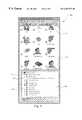
- FIG. 5shows an embodiment of a computer screen that can be used to program various parameters for the embodiment of the security device of FIG. 1 .
- FIG. 6is a flowchart illustrating operation of the embodiments of the security device and display screen of FIG. 1 .
- FIG. 7Ashows a first alternative embodiment of the display screen.
- FIG. 7Bshows a second alternative embodiment of the display screen.
- FIG. 7Cshows a third alternative embodiment of the display screen.
- a network security deviceand in particular, a screen and corresponding method for displaying network traffic information is described in detail herein.
- numerous detailsare provided, such as brief descriptions of various network components that send and receive network traffic (see, e.g., FIG. 3) to provide a thorough understanding of embodiments of the invention.
- One skilled in the artwill recognize that embodiments of the invention can be practiced without one or more of these details or methods.
- well-known structures or operationsare not shown or not described in detail to avoid obscuring aspects of embodiments of the invention.
- FIG. 1shown generally at 100 , is an embodiment of a network security device according to the invention that can be used as part of a company's firewall system.
- the security device 100is contained within a housing 102 , with an embodiment of a display screen 104 located at a front face of the security device 100 .
- the security device 100is a stand-alone network security appliance that can be “plugged-in” between a router 308 and a company's internal computer network (see, e.g., FIG. 3 ).
- a size of the housing 102can be 15.5 ⁇ 2.85 ⁇ 10.5 inches, with the security device 100 having a weight of about 8 pounds, although other sizes and weights are possible.
- the screen 104is provided with three representations of network sources/destinations.
- a “TRUSTED” labelrepresents the company's internal or “trusted” network (e.g., an “Intranet”), which is often desired to be protected to a maximum practical amount.
- An “EXTERNAL” labelrepresents an external network (e.g., the Internet) that presents a security challenge to the company's internal network.
- An “OPTIONAL” labelrepresents an optional network that the company may set up that is accessible to the general public.
- the optional network(sometimes referred to as a “demilitarized zone” or DMZ) allows customers to send e-mail to the company or to browse through the company's web site on the World Wide Web (WWW).
- the “TRUSTED” labelhas an indicator 106 associated therewith.
- the “OPTIONAL” and “EXTERNAL” labelshave indicators 108 and 110 respectively associated therewith.
- a first directional indicator 112when illuminated or activated, represents a packet of information sent from the external network to the trusted network.
- a second directional indicator 114represents a packet of information sent from the trusted network to the external network.
- a third directional indicator 116represents a packet sent from the optional network to the trusted network
- a fourth directional indicator 118represents a packet sent from the trusted network to the optional network.
- a fifth directional indicator 120represents a packet of information sent from the optional network to the external network
- a sixth directional indicator 122represents a packet of information sent from the external network to the optional network.
- the directional indicators 112 - 122are “directional” in that they are in the form of arrows.
- packets moving in one directioncan be represented by directional indicators having a first color
- packets moving in the opposite directioncan be represented by directional indicators having a different color.
- a load indicator 124 of the screen 104represents a load on a microprocessor 408 (see, e.g., FIG. 4) of the security device 100 .
- a traffic volume indicator 126indicates a level of network traffic through the security device 100 .
- There are several possible ways of indicating a load for the load indicator 124 and a level of network traffic for the traffic volume indicator 126For example, a “low” range can be shown with a green light, with a “higher” range shown in yellow. Thus, different levels are indicated by different colors. In other embodiments, a single color can be used, with a level of network traffic or a load on the microprocessor 408 indicated by an amount or height of a colored portion illuminated in the load indicator 124 or in the traffic volume indicator 126 .
- the screen 104further has an “armed” indicator 130 to indicate that the security device 100 is operational.
- a “disarmed” indicator 128if activated, indicates that the security device 100 has detected an error, has shut down all of its interfaces, and will not forward any packets.
- System indicators 132 and 134respectively indicate whether the security device 100 is running from a primary or secondary configuration.
- the screen 104can comprise a multiple-segment liquid crystal display (LCD) or a multiple-segment, negative mode LCD.
- LCDliquid crystal display
- negative mode LCDoperates in an opposite manner.
- a backing(not shown), such as one having a silver color, for the screen 104 determines the different shades when the screen 104 is supplied with power (e.g., the screen 104 is silver when it is not supplied with power, and individual segments are dark when supplied with power). If the various indicators shown in the screen 104 of FIG.
- the screen 104can comprise a backlit indicator panel with various colored light-emitting diodes (LEDs) providing the different colors of the indicators.
- LEDslight-emitting diodes
- Other types of display technology that can be usedinclude a field emitter display (FED), active matrix display, cathode ray tube (CRT), etc. Specific details of how the screen 104 functions to provide information associated with network traffic will be described in further detail below with reference to FIG. 6 .
- FIG. 2shows a rear panel view of the security device 100 .
- An AC receptacle 200receives AC power (e.g., 100-240V AC, 50/60 Hz) provided to the security device 100 from an AC power supply (not shown).
- a “power-on” LED 202indicates if the security device 100 is receiving AC power.
- a power switch 204turns the security device 100 on or off.
- a slot 206accepts a Personal Computer Memory Card International Association (PCM-CIA) card, such as a modem card to facilitate out-of-band transmissions or management.
- PCM-CIAPersonal Computer Memory Card International Association
- a Type II PCM-CIA card slotcan be used for the slot 206 .
- a console port 208allows a workstation to be coupled thereto, so as to configure the security device 100 from any Service Management System (SMS) workstation (see, e.g., an SMS station 324 in FIG. 3.)
- SMSService Management System
- a serial port 210provides a serial interface for supported modems.
- a DB-9 serial port having a standard nine-pin RS-232-C interfacecan be used for the serial port 210 .
- the security device 100has three Ethernet ports using standard eight-pin RJ-45 connectors: a port 212 for connection to an external network 218 , a port 214 for connection to a trusted network 220 , and a port 216 for connection to an optional network 222 .
- Each of the ports 212 , 214 , 216can have LEDs for each interface to indicate link status and card speed (e.g, shown in FIG. 2 as a “10” labeled LED for 10 megabits speed and a “100” labeled LED for 100 megabits), as well as an activity indicator marked as “A” in FIG. 2 .
- the security device 100can be further provided on its back panel with a green light next to either the “10” LED or the “100” LED to signify that there is a good link between the security device 100 and the particular network 218 , 220 , 222 .
- FIG. 3shows the trusted network 220 , the external network 218 , and the optional network 222 in more detail, as well as showing how the security device 100 can be connected to these networks.
- the security device 100is in a position to control and monitor transmission and reception of network traffic (e.g., packets) sent between the trusted network 220 , the external network 218 , and the optional network 222 .
- network traffice.g., packets
- the trusted network 220comprises a network of user workstations 312 , 314 , 316 , and 318 connected by a network bus 319 .
- the trusted network 220can further include an internal server 320 and a log host 322 that receives logs of network traffic from the security device 100 .
- the SMS station 324configures the security device 100 , regulates incoming and outgoing access, and controls logging and notification associated with network traffic through the security device 100 .
- the optional network 222can comprise a public server 310 used in Hyper-Text Transfer Protocol (HTTP) transmissions in connection with the WWW, Simple Mail Transfer Protocol (SMTP) for e-mail transmission and reception, File Transfer Protocol (FTP) communications, and Domain Name System (DNS) for translating domain names into Internet Protocol (IP) addresses, and other associated functions.
- HTTPHyper-Text Transfer Protocol
- SMTPSimple Mail Transfer Protocol
- FTPFile Transfer Protocol
- DNSDomain Name System
- the external network 218includes the Internet (shown as 300 in FIG. 3) connected to the security device 100 via the router 308 .
- Other components of the external network 218 that can be connected to the Internet 300include remote users 306 and miscellaneous external devices/systems 304 .
- An example of the system 304can be a broadcast system that allows software updates for the security device 100 to be externally sent to the SMS station 324 .
- An Extranet 302can be connected to the Internet 300 via a Virtual Private Network (VPN).
- VPNVirtual Private Network
- the Extranet 302is an Internet-like network that a company runs to conduct business with its employees, customers, and/or suppliers.
- Extranet networksare connected to each other and to the Internet 300 by using public wires to connect nodes, with individual Extranets using encryption and other security mechanisms to ensure that only authorized users can access a particular Extranet network.
- FIG. 4shows a block diagram for the security device 100 .
- the security device 100includes three Ethernet cards 402 , 404 , 406 to process network traffic information and data associated with the corresponding external network 218 , trusted network 220 , and optional network 222 .
- the Ethernet cards 402 , 404 , 406are respectively coupled to the ports 212 , 214 , 216 .
- the Ethernet cards 402 , 404 , 406are in turn operatively coupled to the microprocessor 408 via respective lines 418 , 420 , 422 .
- the microprocessor 408is coupled to the screen 104 by one or more lines 416 that allow the microprocessor 408 to control the individual indicators (see, e.g., FIG. 1) of the screen 104 .
- Ethernet cards 402 , 404 , 406are shown herein, it is to be appreciated that principles of embodiments of the invention can be applied to other types of network systems, protocols, and interfaces (e.g., token rings, AppleTalk, Netware, etc.). Also, although only three Ethernet cards 402 , 404 , 406 and a single microprocessor 408 are shown and described herein, embodiments of the security device 100 can use any number of cards and microprocessors depending on the specific network traffic monitoring requirements of the company.
- a memory 410 having stored thereon a software program 412 to operate the security device 100is coupled to the microprocessor 408 via one or more lines 414 .
- a flash memorycan be used for the memory 410 .
- the software program 412can be any type of computer-readable or computer-executable instructions, such as program modules or macros executable by the microprocessor 408 or by a computer.
- the memory 410 and the software program 412are shown in FIG. 4 as residing within the security device 100 , it is to be appreciated that the memory 410 and/or the software program 412 can be located externally of the security device 100 and connected to the security device 100 via a bus system (e.g. the lines 414 ) that includes a memory bus, peripheral bus, and a local bus (not shown).
- the memory 410 and/or the software program 412can reside in the SMS station 324 of the trusted network 220 .
- the memory 410 and the software program 412can comprise other types of computer-readable media and associated devices that store data accessible by a computer or by the microprocessor 408 , such as magnetic cassettes, digital video disks (DVD), CD-ROMs, Bernoulli cartridges, random access memories (RAMs), read-only memories (ROMs), smart cards, etc., and can include other types of software programs, such as an operating system, one or more application programs, and other programs and data. Consequently, embodiments of the invention are not limited by the specific location of the components shown in FIG. 4, by the type of storage media and their associated devices, or by the specific type of software program stored therein.
- the software program 412can be configured to operate the security device 100 and the screen 104 according to the some of the following illustrative parameters and instructions.
- a policy for the security device 100 regarding a default disposition of packets(sometimes referred to as a “stance”) is set.
- the stanceprotects against attacks based on new, unfamiliar, or obscure transmissions/receptions.
- the stancedictates what the security device 100 will do with any given packet in the absence of explicit instructions.
- a common stanceis to discard or refuse to pass all packets that are not explicitly allowed, often stated as “that which is not explicitly allowed is denied.”
- a less-secure stance that can also be implementedis stated as “what is not denied is allowed.”
- the security device 100can use traditional packet filtering or traditional proxies (both described above) to control access to and from the trusted network 220 , external network 218 , and optional network 222 .
- the security device 100can also use other types of filtering mechanisms. Examples include stateful dynamic packet filtering methods that build rules dynamically depending on the conditions of the network, and transparent proxies that work at the application level to ensure that ports/protocols necessary to pass packets are opened and closed dynamically.
- the security device 100can be configured such that a particular user workstation 312 (see, e.g., FIG. 3) cannot accept any kind of packet from the Internet 300 of the external network 218 but can accept packets from other sources. Additionally, the security device 100 can be programmed such that the user workstation 316 cannot accept e-mail messages from either the optional network 222 or the external network 218 , but can be configured to accept other types of packets.
- the security device 100can be configured to automatically add the IP address of the remote user 306 to a “blocked sites list,” making activities such as port probes increasingly difficult to carry out by hackers.
- the software program 412can instruct the security device 100 to log and record activities such as if the remote user 306 tries to repeatedly access the SMS station 324 over a ten-minute period during late evening hours, which is often indicative of a hacker trying to break into the trusted network 220 .
- the IP address of the remote user 306is added to the blocked site list, and the hacker's activities are recorded in the log host 322 (see, e.g., FIG. 3 ), with an appropriate notification sent to a system administrator for the trusted network 220 .
- the security device 100is configured by the SMS station 324 using a direct connection to a dedicated serial port such as the console port 208 (see, e.g., FIG. 2) or by using an encrypted network connection.
- An encrypted network connectionallows the system administrator to log in from remote locations to make changes or to check the status of the security device 100 .
- FIG. 5shows a software application window 500 , such as that for a software application running on Microsoft Windows® operating system, that can be used to configure the security device 100 via the SMS station 324 .
- a first frame 502shows individual icons, such as an FTP icon 504 , that represent each network service. Double-clicking on an icon displays its properties windows, where the system administrator can configure access controls and logging for that particular service.
- a second frame 506shows various configuration settings. For instance, a setting 512 allows the system administrator to set the stance for the security device 100 .
- a setting 508when checked, automatically blocks sites (e.g., the IP address of the remote user 306 ) that attempt to use a blocked port.
- sitese.g., the IP address of the remote user 306
- a setting 510sets properties for an HTTP proxy (e.g., an application-level firewall that examines contents of Internet and WWW packets from the external network 218 ).
- HTTP proxye.g., an application-level firewall that examines contents of Internet and WWW packets from the external network 218 .
- Many other possible configurations and settings other than those shown in FIG. 5can be used for the security device 100 .
- the methods, devices, systems, software programs, and related components described hereinprovide in a broad sense a “facility” that operates to monitor, process, and display information associated with network traffic. These elements can operate independently or cooperatively to perform the various functions described herein.
- FIG. 6shows a flowchart that is read in conjunction with FIG. 1 and that illustrates operation of the screen 104 as the security device 100 processes network traffic.
- the security device 100is initialized at step 600 , such as by supplying AC power to the security device and booting up the software program 412 .
- the “armed” indicator 130is illuminated at step 602 to indicate that the security device 100 is operational.
- the security device 100monitors network traffic by monitoring if a packet is sent from a source (e.g., the external network 218 ) towards a particular destination (e.g., the trusted network 220 ).
- a sourcee.g., the external network 218
- a particular destinatione.g., the trusted network 220
- the software program 412 and/or the microprocessor 408analyzes the packet at step 608 using packet filtering methods to determine if the packet is coming from an authorized source. For instance, the software program 412 checks if an IP address of the packet is that of a remote user 306 in the external network 218 that has been placed on the blocked site list. Another determination that can be made at step 608 is whether the packet itself is authorized, as determined by an application-level proxy program that examines the content of the packet. If the source and/or the packet are not authorized, then the software program 412 causes to be illuminated in red a source indicator (e.g., the indicator 110 associated with the “EXTERNAL” label of FIG.
- a source indicatore.g., the indicator 110 associated with the “EXTERNAL” label of FIG.
- the source indicator 110can stay illuminated for a period of time, such as from four to five seconds, to indicate that the packet is being denied at the port 212 corresponding to the external network 218 (see, e.g., FIG. 2 ), as indicated at step 626 . Thereafter, the security device 100 resumes monitoring network traffic at step 604 .
- the source indicatore.g., the indicator 110 for the “EXTERNAL” label in FIG. 1 is illuminated green at step 610 .
- the security device 100determines whether a destination of the packet is authorized to receive the packet. Again, this can be done by the software program 412 by using packet filtering methods to determine whether the destination (e.g., the trusted network 220 ) is authorized to receive traffic from a particular source (e.g., the Internet 300 ), or by using a proxy to determine if the destination is authorized to receive the type of packet (e.g., an e-mail message from the public server 310 of the optional network 222 of FIG. 3 ). If the destination is not authorized to receive the packet, then a destination indicator is illuminated red at step 620 .
- the destination indicatorcan be, for example, the indicator 106 associated with the “TRUSTED” label shown on the screen 104 of FIG.
- the destination indicatorcan remain illuminated for an extended period, such as for five seconds, to indicate that the packet is being rejected at step 622 at that interface. Subsequently, the security device 100 resumes monitoring network traffic at step 604 , and the steps 604 - 626 are repeated as appropriate and as described above.
- a directional indicatoris illuminated at step 614 .
- the directional indicator 112 of FIG. 1pointing from the “EXTERNAL” label to the “TRUSTED” label, is illuminated briefly to indicate allowed traffic from the external network 218 to the trusted network 220 .
- the destination indicatore.g., the indicator 106 for the “TRUSTED” label
- the destination indicatoris illuminated green to indicate that the packet has been accepted at step 618 .
- the packetcan be accepted or passed by connecting the router 308 to an appropriate “route address.”
- a “route address”provides a gateway to an IP address on a network (e.g., an IP address of the workstation 314 of the trusted network 220 of FIG. 3) that the security device 100 recognizes. Thereafter, the security device 100 monitors for the next packet at step 604 .
- the load indicator 124is illuminated at varying levels to indicate a load on the microprocessor 408 as this activity occurs.
- the traffic volume indicator 126is illuminated at various levels and/or colors to indicate the volume of network traffic through the security device 100 .
- the network security device 100While the activities described with reference to FIG. 6 are occurring, various other functions can be performed by the network security device 100 . For example, particular packets that are denied may be concurrently logged in the log host 322 to record the amount of time and number of attempts in which the packet tried to obtain access a particular network. Further, notifications can be automatically sent to the system administrator when any of the activities shown in FIG. 6 are occurring, such as when a packet having an IP address from a blocked site list attempts to access the trusted network 220 . In summary, therefore, embodiments of the screen 104 described above allow a convenient, real-time visual indication of network traffic as it is processed by the security device 100 .
- FIG. 7Ashows a first alternative embodiment of the screen 104 , where the screen 104 is disposed on a software application window 700 , such as that for a software application running on Microsoft Windows® operating system.
- a software application window 700such as that for a software application running on Microsoft Windows® operating system.
- the various indicators of the screen 104are displayed using computer graphics located within the frames 702 and 704 .
- FIG. 7Bshows a second alternative embodiment where the screen 104 is shown on a software application window 702 .
- FIG. 7Bincludes similar computer graphics and indicators as shown in the window 700 of FIG. 7 A.
- FIG. 7Cshows a third alternative embodiment of the screen 104 , also disposed on a software application window 704 .
- the windows 700 , 702 , and 704can run, for example, on a screen 325 of the SMS workstation 324 of FIG. 3 .
- the indicators shown in the windows 700 , 702 , and 704are shown as computer graphics on a computer screen in these embodiments, it is to be appreciated that indicators having these formats can also be implemented on the screen 104 of the security device 100 .
- the teachings provided herein of embodiments of the inventioncan also be applied to other network security devices and display screen systems, not necessarily the screen 104 for a security device 100 as described above.
Landscapes
- Engineering & Computer Science (AREA)
- Computer Networks & Wireless Communication (AREA)
- Signal Processing (AREA)
- Computer Security & Cryptography (AREA)
- Human Computer Interaction (AREA)
- Computer Hardware Design (AREA)
- Computing Systems (AREA)
- General Engineering & Computer Science (AREA)
- Data Exchanges In Wide-Area Networks (AREA)
Abstract
Description
Claims (40)
Priority Applications (3)
| Application Number | Priority Date | Filing Date | Title |
|---|---|---|---|
| US09/307,256US6493752B1 (en) | 1999-05-06 | 1999-05-06 | Device and method for graphically displaying data movement in a secured network |
| AU43481/00AAU4348100A (en) | 1999-05-06 | 2000-04-13 | Device and method for displaying network security information |
| PCT/US2000/009984WO2000069146A1 (en) | 1999-05-06 | 2000-04-13 | Device and method for displaying network security information |
Applications Claiming Priority (1)
| Application Number | Priority Date | Filing Date | Title |
|---|---|---|---|
| US09/307,256US6493752B1 (en) | 1999-05-06 | 1999-05-06 | Device and method for graphically displaying data movement in a secured network |
Publications (1)
| Publication Number | Publication Date |
|---|---|
| US6493752B1true US6493752B1 (en) | 2002-12-10 |
Family
ID=23188914
Family Applications (1)
| Application Number | Title | Priority Date | Filing Date |
|---|---|---|---|
| US09/307,256Expired - LifetimeUS6493752B1 (en) | 1999-05-06 | 1999-05-06 | Device and method for graphically displaying data movement in a secured network |
Country Status (3)
| Country | Link |
|---|---|
| US (1) | US6493752B1 (en) |
| AU (1) | AU4348100A (en) |
| WO (1) | WO2000069146A1 (en) |
Cited By (31)
| Publication number | Priority date | Publication date | Assignee | Title |
|---|---|---|---|---|
| US20020078377A1 (en)* | 2000-12-15 | 2002-06-20 | Ching-Jye Chang | Method and apparatus in an application framework system for providing a port and network hardware resource firewall for distributed applications |
| US20020078231A1 (en)* | 2000-12-15 | 2002-06-20 | Ibm Corporation | Simplified network packet analyzer for distributed packet snooper |
| US20020099959A1 (en)* | 2000-11-13 | 2002-07-25 | Redlich Ron M. | Data security system and method responsive to electronic attacks |
| US6714970B1 (en)* | 2000-10-26 | 2004-03-30 | International Business Machines Corporation | Protecting open world wide web sites from known malicious users by diverting requests from malicious users to alias addresses for the protected sites |
| US20040160899A1 (en)* | 2003-02-18 | 2004-08-19 | W-Channel Inc. | Device for observing network packets |
| US20040230639A1 (en)* | 2003-05-14 | 2004-11-18 | Microsoft Corporation | Method and apparatus for configuring servers |
| US20060031480A1 (en)* | 2000-07-24 | 2006-02-09 | Sasa Nijemcevic | Network management support for OAM functionality and method therefore |
| US20060168152A1 (en)* | 2003-06-30 | 2006-07-27 | Kirk Soluk | Method and apparatus for configuring a server |
| US7089588B2 (en)* | 2000-01-19 | 2006-08-08 | Reynolds And Reynolds Holdings, Inc. | Performance path method and apparatus for exchanging data among systems using different data formats |
| US7131141B1 (en)* | 2001-07-27 | 2006-10-31 | At&T Corp. | Method and apparatus for securely connecting a plurality of trust-group networks, a protected resource network and an untrusted network |
| US20060250983A1 (en)* | 2005-03-31 | 2006-11-09 | Iris Corporation Berhad | Method of and arrangement for establishing network connections in an ethernet environment |
| US7237264B1 (en) | 2001-06-04 | 2007-06-26 | Internet Security Systems, Inc. | System and method for preventing network misuse |
| US20070147262A1 (en)* | 2005-12-22 | 2007-06-28 | Jeffrey Aaron | Methods, communication networks, and computer program products for storing and/or logging traffic associated with a network element based on whether the network element can be trusted |
| US7340776B2 (en) | 2001-01-31 | 2008-03-04 | International Business Machines Corporation | Method and system for configuring and scheduling security audits of a computer network |
| US7370360B2 (en) | 2002-05-13 | 2008-05-06 | International Business Machines Corporation | Computer immune system and method for detecting unwanted code in a P-code or partially compiled native-code program executing within a virtual machine |
| US7464410B1 (en)* | 2001-08-30 | 2008-12-09 | At&T Corp. | Protection against flooding of a server |
| WO2007002621A3 (en)* | 2005-06-28 | 2009-04-16 | Yahoo Inc | Apparatus and method for content annotation and conditional annotation retrieval in a search context |
| US7565549B2 (en) | 2002-01-04 | 2009-07-21 | International Business Machines Corporation | System and method for the managed security control of processes on a computer system |
| US7640590B1 (en)* | 2004-12-21 | 2009-12-29 | Symantec Corporation | Presentation of network source and executable characteristics |
| US7657938B2 (en) | 2003-10-28 | 2010-02-02 | International Business Machines Corporation | Method and system for protecting computer networks by altering unwanted network data traffic |
| US7739494B1 (en) | 2003-04-25 | 2010-06-15 | Symantec Corporation | SSL validation and stripping using trustworthiness factors |
| US7881215B1 (en)* | 2004-03-18 | 2011-02-01 | Avaya Inc. | Stateful and stateless data processing |
| US7913303B1 (en) | 2003-01-21 | 2011-03-22 | International Business Machines Corporation | Method and system for dynamically protecting a computer system from attack |
| US7921459B2 (en)* | 2000-04-28 | 2011-04-05 | International Business Machines Corporation | System and method for managing security events on a network |
| US7936671B1 (en)* | 2007-11-12 | 2011-05-03 | Marvell International Ltd. | Cable far end port identification using repeating link state patterns |
| US7991917B1 (en)* | 2000-07-05 | 2011-08-02 | Mcafee, Inc. | High performance packet processing using a general purpose processor |
| US8006243B2 (en) | 1999-12-07 | 2011-08-23 | International Business Machines Corporation | Method and apparatus for remote installation of network drivers and software |
| US8332947B1 (en) | 2006-06-27 | 2012-12-11 | Symantec Corporation | Security threat reporting in light of local security tools |
| US20140258528A1 (en)* | 2013-03-08 | 2014-09-11 | Edward Blake MILLER | System and method for managing attempted access of objectionable content and/or tampering with a content filtering device |
| US9027121B2 (en) | 2000-10-10 | 2015-05-05 | International Business Machines Corporation | Method and system for creating a record for one or more computer security incidents |
| US9692784B1 (en)* | 2016-10-25 | 2017-06-27 | Fortress Cyber Security, LLC | Security appliance |
Families Citing this family (2)
| Publication number | Priority date | Publication date | Assignee | Title |
|---|---|---|---|---|
| AUPR435501A0 (en)* | 2001-04-11 | 2001-05-17 | Firebridge Systems Pty Ltd | Network security system |
| JP2010526510A (en)* | 2007-05-09 | 2010-07-29 | サムスン エレクトロニクス カンパニー リミテッド | Frame transmission / reception method in mobile communication system |
Citations (10)
| Publication number | Priority date | Publication date | Assignee | Title |
|---|---|---|---|---|
| US5699513A (en)* | 1995-03-31 | 1997-12-16 | Motorola, Inc. | Method for secure network access via message intercept |
| US5768552A (en) | 1990-09-28 | 1998-06-16 | Silicon Graphics, Inc. | Graphical representation of computer network topology and activity |
| US5864666A (en) | 1996-12-23 | 1999-01-26 | International Business Machines Corporation | Web-based administration of IP tunneling on internet firewalls |
| US5892903A (en)* | 1996-09-12 | 1999-04-06 | Internet Security Systems, Inc. | Method and apparatus for detecting and identifying security vulnerabilities in an open network computer communication system |
| US6108310A (en)* | 1997-09-12 | 2000-08-22 | Hewlett-Packard Company | Display of network traffic attributes based on frequency distribution |
| US6148342A (en)* | 1998-01-27 | 2000-11-14 | Ho; Andrew P. | Secure database management system for confidential records using separately encrypted identifier and access request |
| US6209033B1 (en)* | 1995-02-01 | 2001-03-27 | Cabletron Systems, Inc. | Apparatus and method for network capacity evaluation and planning |
| US6212633B1 (en)* | 1998-06-26 | 2001-04-03 | Vlsi Technology, Inc. | Secure data communication over a memory-mapped serial communications interface utilizing a distributed firewall |
| US6304969B1 (en)* | 1999-03-16 | 2001-10-16 | Webiv Networks, Inc. | Verification of server authorization to provide network resources |
| US6317837B1 (en)* | 1998-09-01 | 2001-11-13 | Applianceware, Llc | Internal network node with dedicated firewall |
- 1999
- 1999-05-06USUS09/307,256patent/US6493752B1/ennot_activeExpired - Lifetime
- 2000
- 2000-04-13WOPCT/US2000/009984patent/WO2000069146A1/enactiveApplication Filing
- 2000-04-13AUAU43481/00Apatent/AU4348100A/ennot_activeAbandoned
Patent Citations (10)
| Publication number | Priority date | Publication date | Assignee | Title |
|---|---|---|---|---|
| US5768552A (en) | 1990-09-28 | 1998-06-16 | Silicon Graphics, Inc. | Graphical representation of computer network topology and activity |
| US6209033B1 (en)* | 1995-02-01 | 2001-03-27 | Cabletron Systems, Inc. | Apparatus and method for network capacity evaluation and planning |
| US5699513A (en)* | 1995-03-31 | 1997-12-16 | Motorola, Inc. | Method for secure network access via message intercept |
| US5892903A (en)* | 1996-09-12 | 1999-04-06 | Internet Security Systems, Inc. | Method and apparatus for detecting and identifying security vulnerabilities in an open network computer communication system |
| US5864666A (en) | 1996-12-23 | 1999-01-26 | International Business Machines Corporation | Web-based administration of IP tunneling on internet firewalls |
| US6108310A (en)* | 1997-09-12 | 2000-08-22 | Hewlett-Packard Company | Display of network traffic attributes based on frequency distribution |
| US6148342A (en)* | 1998-01-27 | 2000-11-14 | Ho; Andrew P. | Secure database management system for confidential records using separately encrypted identifier and access request |
| US6212633B1 (en)* | 1998-06-26 | 2001-04-03 | Vlsi Technology, Inc. | Secure data communication over a memory-mapped serial communications interface utilizing a distributed firewall |
| US6317837B1 (en)* | 1998-09-01 | 2001-11-13 | Applianceware, Llc | Internal network node with dedicated firewall |
| US6304969B1 (en)* | 1999-03-16 | 2001-10-16 | Webiv Networks, Inc. | Verification of server authorization to provide network resources |
Cited By (45)
| Publication number | Priority date | Publication date | Assignee | Title |
|---|---|---|---|---|
| US8006243B2 (en) | 1999-12-07 | 2011-08-23 | International Business Machines Corporation | Method and apparatus for remote installation of network drivers and software |
| US7089588B2 (en)* | 2000-01-19 | 2006-08-08 | Reynolds And Reynolds Holdings, Inc. | Performance path method and apparatus for exchanging data among systems using different data formats |
| US7921459B2 (en)* | 2000-04-28 | 2011-04-05 | International Business Machines Corporation | System and method for managing security events on a network |
| US8555374B2 (en) | 2000-07-05 | 2013-10-08 | Mcafee, Inc. | High performance packet processing using a general purpose processor |
| US7991917B1 (en)* | 2000-07-05 | 2011-08-02 | Mcafee, Inc. | High performance packet processing using a general purpose processor |
| US20060031480A1 (en)* | 2000-07-24 | 2006-02-09 | Sasa Nijemcevic | Network management support for OAM functionality and method therefore |
| US9027121B2 (en) | 2000-10-10 | 2015-05-05 | International Business Machines Corporation | Method and system for creating a record for one or more computer security incidents |
| US6714970B1 (en)* | 2000-10-26 | 2004-03-30 | International Business Machines Corporation | Protecting open world wide web sites from known malicious users by diverting requests from malicious users to alias addresses for the protected sites |
| US7146644B2 (en)* | 2000-11-13 | 2006-12-05 | Digital Doors, Inc. | Data security system and method responsive to electronic attacks |
| US20020099959A1 (en)* | 2000-11-13 | 2002-07-25 | Redlich Ron M. | Data security system and method responsive to electronic attacks |
| US20020078231A1 (en)* | 2000-12-15 | 2002-06-20 | Ibm Corporation | Simplified network packet analyzer for distributed packet snooper |
| US20020078377A1 (en)* | 2000-12-15 | 2002-06-20 | Ching-Jye Chang | Method and apparatus in an application framework system for providing a port and network hardware resource firewall for distributed applications |
| US7269647B2 (en) | 2000-12-15 | 2007-09-11 | International Business Machines Corporation | Simplified network packet analyzer for distributed packet snooper |
| US7296292B2 (en)* | 2000-12-15 | 2007-11-13 | International Business Machines Corporation | Method and apparatus in an application framework system for providing a port and network hardware resource firewall for distributed applications |
| US7340776B2 (en) | 2001-01-31 | 2008-03-04 | International Business Machines Corporation | Method and system for configuring and scheduling security audits of a computer network |
| US7712138B2 (en) | 2001-01-31 | 2010-05-04 | International Business Machines Corporation | Method and system for configuring and scheduling security audits of a computer network |
| US7237264B1 (en) | 2001-06-04 | 2007-06-26 | Internet Security Systems, Inc. | System and method for preventing network misuse |
| US7131141B1 (en)* | 2001-07-27 | 2006-10-31 | At&T Corp. | Method and apparatus for securely connecting a plurality of trust-group networks, a protected resource network and an untrusted network |
| US7464410B1 (en)* | 2001-08-30 | 2008-12-09 | At&T Corp. | Protection against flooding of a server |
| US7565549B2 (en) | 2002-01-04 | 2009-07-21 | International Business Machines Corporation | System and method for the managed security control of processes on a computer system |
| US7673137B2 (en) | 2002-01-04 | 2010-03-02 | International Business Machines Corporation | System and method for the managed security control of processes on a computer system |
| US7370360B2 (en) | 2002-05-13 | 2008-05-06 | International Business Machines Corporation | Computer immune system and method for detecting unwanted code in a P-code or partially compiled native-code program executing within a virtual machine |
| US7913303B1 (en) | 2003-01-21 | 2011-03-22 | International Business Machines Corporation | Method and system for dynamically protecting a computer system from attack |
| US20040160899A1 (en)* | 2003-02-18 | 2004-08-19 | W-Channel Inc. | Device for observing network packets |
| US7739494B1 (en) | 2003-04-25 | 2010-06-15 | Symantec Corporation | SSL validation and stripping using trustworthiness factors |
| US7454483B2 (en) | 2003-05-14 | 2008-11-18 | Microsoft Corporation | Method and apparatus for configuring servers |
| US20040230639A1 (en)* | 2003-05-14 | 2004-11-18 | Microsoft Corporation | Method and apparatus for configuring servers |
| US7620704B2 (en)* | 2003-06-30 | 2009-11-17 | Microsoft Corporation | Method and apparatus for configuring a server |
| US20060168152A1 (en)* | 2003-06-30 | 2006-07-27 | Kirk Soluk | Method and apparatus for configuring a server |
| US7657938B2 (en) | 2003-10-28 | 2010-02-02 | International Business Machines Corporation | Method and system for protecting computer networks by altering unwanted network data traffic |
| US7881215B1 (en)* | 2004-03-18 | 2011-02-01 | Avaya Inc. | Stateful and stateless data processing |
| US7640590B1 (en)* | 2004-12-21 | 2009-12-29 | Symantec Corporation | Presentation of network source and executable characteristics |
| US20060250983A1 (en)* | 2005-03-31 | 2006-11-09 | Iris Corporation Berhad | Method of and arrangement for establishing network connections in an ethernet environment |
| WO2007002621A3 (en)* | 2005-06-28 | 2009-04-16 | Yahoo Inc | Apparatus and method for content annotation and conditional annotation retrieval in a search context |
| US20070147262A1 (en)* | 2005-12-22 | 2007-06-28 | Jeffrey Aaron | Methods, communication networks, and computer program products for storing and/or logging traffic associated with a network element based on whether the network element can be trusted |
| US8332947B1 (en) | 2006-06-27 | 2012-12-11 | Symantec Corporation | Security threat reporting in light of local security tools |
| US8934340B1 (en) | 2007-11-12 | 2015-01-13 | Marvell International Ltd. | Apparatus and method for identifying, based on an alternating pattern, a port to which a cable is connected |
| US7936671B1 (en)* | 2007-11-12 | 2011-05-03 | Marvell International Ltd. | Cable far end port identification using repeating link state patterns |
| US20140258528A1 (en)* | 2013-03-08 | 2014-09-11 | Edward Blake MILLER | System and method for managing attempted access of objectionable content and/or tampering with a content filtering device |
| US9118603B2 (en)* | 2013-03-08 | 2015-08-25 | Edward Blake MILLER | System and method for managing attempted access of objectionable content and/or tampering with a content filtering device |
| US9692784B1 (en)* | 2016-10-25 | 2017-06-27 | Fortress Cyber Security, LLC | Security appliance |
| US9967280B1 (en) | 2016-10-25 | 2018-05-08 | Fortress Cyber Security, LLC | Security appliance |
| US20180255096A1 (en)* | 2016-10-25 | 2018-09-06 | Fortress Cyber Security, LLC | Security appliance |
| US10542038B2 (en) | 2016-10-25 | 2020-01-21 | Fortress Information Security, Llc | Security appliance |
| US11575705B2 (en) | 2016-10-25 | 2023-02-07 | Fortress Cyber Security, LLC | Security appliance |
Also Published As
| Publication number | Publication date |
|---|---|
| WO2000069146A1 (en) | 2000-11-16 |
| AU4348100A (en) | 2000-11-21 |
Similar Documents
| Publication | Publication Date | Title |
|---|---|---|
| US6493752B1 (en) | Device and method for graphically displaying data movement in a secured network | |
| US12316680B2 (en) | Integrated security and threat prevention and detection platform | |
| US20210029547A1 (en) | System and method for filtering access points presented to a user and locking onto an access point | |
| US10084750B2 (en) | Policy-based content filtering | |
| US8701177B2 (en) | Method and apparatus for graphical presentation of firewall security policy | |
| US6981143B2 (en) | System and method for providing connection orientation based access authentication | |
| US7359962B2 (en) | Network security system integration | |
| EP0658837B1 (en) | Method for controlling computer network security | |
| US20030131263A1 (en) | Methods and systems for firewalling virtual private networks | |
| Chopra | Security issues of firewall | |
| CN112751843A (en) | Network safety protection system of railway power supply system | |
| Haeni | Firewall penetration testing | |
| Wool | Packet filtering and stateful firewalls | |
| Cisco | Glossary | |
| Cisco | Private Internet ExchangeReference Guide | |
| Cisco | Private Internet ExchangeReference Guide | |
| Cisco | Private Internet ExchangeReference Guide | |
| Cisco | Private Internet ExchangeReference Guide | |
| Cisco | Cisco Intrusion Detection System Sensor Device Manager Configuration Note Version 3.1 | |
| JP2005109847A (en) | Security management device | |
| Cooper | Network Security Management with Firewalls | |
| Abiola Odunmbaku et al. | Network Administration-Installation and Configuration of eBox Platform | |
| Ly et al. | Firewall: Technologies and Practices | |
| Paez | Security Technology & Terminology Guide |
Legal Events
| Date | Code | Title | Description |
|---|---|---|---|
| STCF | Information on status: patent grant | Free format text:PATENTED CASE | |
| CC | Certificate of correction | ||
| FPAY | Fee payment | Year of fee payment:4 | |
| AS | Assignment | Owner name:SILICON VALLEY BANK, CALIFORNIA Free format text:SECURITY AGREEMENT;ASSIGNORS:WATCHGUARD TECHNOLOGIES, INC.;GLADIATOR CORPORATION;REEL/FRAME:023098/0771 Effective date:20090730 Owner name:SILICON VALLEY BANK,CALIFORNIA Free format text:SECURITY AGREEMENT;ASSIGNORS:WATCHGUARD TECHNOLOGIES, INC.;GLADIATOR CORPORATION;REEL/FRAME:023098/0771 Effective date:20090730 | |
| FPAY | Fee payment | Year of fee payment:8 | |
| AS | Assignment | Owner name:BANK OF MONTREAL, AS ADMINISTRATIVE AGENT, ILLINOI Free format text:SECURITY AGREEMENT;ASSIGNOR:WATCHGUARD TECHNOLOGIES, INC.;REEL/FRAME:028488/0917 Effective date:20120628 Owner name:WATCHGUARD TECHNOLOGIES, INC., WASHINGTON Free format text:RELEASE BY SECURED PARTY;ASSIGNOR:SILICON VALLEY BANK;REEL/FRAME:028477/0268 Effective date:20120628 Owner name:GLADIATOR CORPORATION, WASHINGTON Free format text:RELEASE BY SECURED PARTY;ASSIGNOR:SILICON VALLEY BANK;REEL/FRAME:028477/0268 Effective date:20120628 | |
| FPAY | Fee payment | Year of fee payment:12 | |
| AS | Assignment | Owner name:WATCHGUARD TECHNOLOGIES, INC., WASHINGTON Free format text:RELEASE BY SECURED PARTY;ASSIGNOR:BANK OF MONTREAL, AS ADMINISTRATIVE AGENT;REEL/FRAME:035995/0466 Effective date:20150629 Owner name:GOLDMAN SACHS SPECIALTY LENDING GROUP, L.P., AS CO Free format text:SECURITY INTEREST;ASSIGNOR:WATCHGUARD TECHNOLOGIES, INC.;REEL/FRAME:036038/0455 Effective date:20150629 | |
| AS | Assignment | Owner name:GOLDMAN SACHS SPECIALTY LENDING GROUP. L.P., TEXAS Free format text:CHANGE OF ADDRESS FOR ASSIGNEE;ASSIGNOR:GOLDMAN SACHS SPECIALTY LENDING GROUP. L.P.;REEL/FRAME:050195/0673 Effective date:20190826 | |
| AS | Assignment | Owner name:WATCHGUARD TECHNOLOGIES, INC., WASHINGTON Free format text:RELEASE BY SECURED PARTY;ASSIGNOR:GOLDMAN SACHS SPECIALTY LENDING GROUP, L.P.;REEL/FRAME:052801/0422 Effective date:20200601 |