US6493689B2 - Neural net controller for noise and vibration reduction - Google Patents
Neural net controller for noise and vibration reductionDownload PDFInfo
- Publication number
- US6493689B2 US6493689B2US09/752,180US75218000AUS6493689B2US 6493689 B2US6493689 B2US 6493689B2US 75218000 AUS75218000 AUS 75218000AUS 6493689 B2US6493689 B2US 6493689B2
- Authority
- US
- United States
- Prior art keywords
- noise
- emulator
- vibration
- input
- neurons
- Prior art date
- Legal status (The legal status is an assumption and is not a legal conclusion. Google has not performed a legal analysis and makes no representation as to the accuracy of the status listed.)
- Expired - Lifetime
Links
- 230000001537neural effectEffects0.000titleclaimsdescription57
- 230000009467reductionEffects0.000titledescription18
- 238000013528artificial neural networkMethods0.000claimsabstractdescription65
- 239000013598vectorSubstances0.000claimsdescription52
- 210000002569neuronAnatomy0.000claimsdescription46
- 230000006870functionEffects0.000claimsdescription37
- 238000004422calculation algorithmMethods0.000claimsdescription23
- 239000012530fluidSubstances0.000claimsdescription23
- 230000003044adaptive effectEffects0.000claimsdescription17
- 238000005259measurementMethods0.000claimsdescription14
- 238000007781pre-processingMethods0.000claimsdescription11
- 238000001914filtrationMethods0.000claimsdescription9
- 238000012546transferMethods0.000claimsdescription3
- 239000007788liquidSubstances0.000claims2
- 239000011159matrix materialSubstances0.000abstractdescription23
- 238000000034methodMethods0.000description32
- 239000000523sampleSubstances0.000description25
- 238000012549trainingMethods0.000description23
- 230000008569processEffects0.000description13
- 230000003111delayed effectEffects0.000description12
- 238000012545processingMethods0.000description11
- 238000013459approachMethods0.000description9
- BCCGKQFZUUQSEX-WBPXWQEISA-N(2r,3r)-2,3-dihydroxybutanedioic acid;3,4-dimethyl-2-phenylmorpholineChemical compoundOC(=O)[C@H](O)[C@@H](O)C(O)=O.OC(=O)[C@H](O)[C@@H](O)C(O)=O.O1CCN(C)C(C)C1C1=CC=CC=C1BCCGKQFZUUQSEX-WBPXWQEISA-N0.000description7
- 238000010586diagramMethods0.000description6
- 230000000694effectsEffects0.000description6
- 230000005284excitationEffects0.000description6
- 230000006399behaviorEffects0.000description5
- 230000008859changeEffects0.000description5
- 230000033001locomotionEffects0.000description5
- 230000007246mechanismEffects0.000description5
- 230000002441reversible effectEffects0.000description5
- 238000004088simulationMethods0.000description5
- 230000002123temporal effectEffects0.000description5
- 230000006978adaptationEffects0.000description4
- 230000004075alterationEffects0.000description4
- 238000001514detection methodMethods0.000description4
- 230000003993interactionEffects0.000description4
- 230000004044responseEffects0.000description4
- 238000004364calculation methodMethods0.000description3
- 238000012937correctionMethods0.000description3
- 238000004519manufacturing processMethods0.000description3
- 238000009987spinningMethods0.000description3
- 238000003860storageMethods0.000description3
- XLYOFNOQVPJJNP-UHFFFAOYSA-NwaterSubstancesOXLYOFNOQVPJJNP-UHFFFAOYSA-N0.000description3
- 230000004913activationEffects0.000description2
- 238000013480data collectionMethods0.000description2
- 230000001419dependent effectEffects0.000description2
- 238000006073displacement reactionMethods0.000description2
- 238000005516engineering processMethods0.000description2
- 230000006872improvementEffects0.000description2
- 238000005312nonlinear dynamicMethods0.000description2
- 230000010349pulsationEffects0.000description2
- 238000011160researchMethods0.000description2
- 230000007704transitionEffects0.000description2
- DNTFEAHNXKUSKQ-RFZPGFLSSA-N(1r,2r)-2-aminocyclopentane-1-sulfonic acidChemical compoundN[C@@H]1CCC[C@H]1S(O)(=O)=ODNTFEAHNXKUSKQ-RFZPGFLSSA-N0.000description1
- 230000009471actionEffects0.000description1
- 230000008901benefitEffects0.000description1
- 230000001427coherent effectEffects0.000description1
- 238000002485combustion reactionMethods0.000description1
- 230000008878couplingEffects0.000description1
- 238000010168coupling processMethods0.000description1
- 238000005859coupling reactionMethods0.000description1
- 238000007405data analysisMethods0.000description1
- 230000007423decreaseEffects0.000description1
- 238000013461designMethods0.000description1
- 230000009977dual effectEffects0.000description1
- 230000008030eliminationEffects0.000description1
- 238000003379elimination reactionMethods0.000description1
- 239000002360explosiveSubstances0.000description1
- 230000007274generation of a signal involved in cell-cell signalingEffects0.000description1
- 230000001939inductive effectEffects0.000description1
- 238000009413insulationMethods0.000description1
- 238000013507mappingMethods0.000description1
- 238000003062neural network modelMethods0.000description1
- 238000005457optimizationMethods0.000description1
- 210000004205output neuronAnatomy0.000description1
- 230000002250progressing effectEffects0.000description1
- 230000005855radiationEffects0.000description1
- 238000012827research and developmentMethods0.000description1
- 239000003381stabilizerSubstances0.000description1
- 238000012360testing methodMethods0.000description1
- 230000009466transformationEffects0.000description1
Images


Classifications
- F—MECHANICAL ENGINEERING; LIGHTING; HEATING; WEAPONS; BLASTING
- F16—ENGINEERING ELEMENTS AND UNITS; GENERAL MEASURES FOR PRODUCING AND MAINTAINING EFFECTIVE FUNCTIONING OF MACHINES OR INSTALLATIONS; THERMAL INSULATION IN GENERAL
- F16F—SPRINGS; SHOCK-ABSORBERS; MEANS FOR DAMPING VIBRATION
- F16F15/00—Suppression of vibrations in systems; Means or arrangements for avoiding or reducing out-of-balance forces, e.g. due to motion
- F16F15/02—Suppression of vibrations of non-rotating, e.g. reciprocating systems; Suppression of vibrations of rotating systems by use of members not moving with the rotating systems
- G—PHYSICS
- G10—MUSICAL INSTRUMENTS; ACOUSTICS
- G10K—SOUND-PRODUCING DEVICES; METHODS OR DEVICES FOR PROTECTING AGAINST, OR FOR DAMPING, NOISE OR OTHER ACOUSTIC WAVES IN GENERAL; ACOUSTICS NOT OTHERWISE PROVIDED FOR
- G10K11/00—Methods or devices for transmitting, conducting or directing sound in general; Methods or devices for protecting against, or for damping, noise or other acoustic waves in general
- G10K11/16—Methods or devices for protecting against, or for damping, noise or other acoustic waves in general
- G10K11/175—Methods or devices for protecting against, or for damping, noise or other acoustic waves in general using interference effects; Masking sound
- G10K11/178—Methods or devices for protecting against, or for damping, noise or other acoustic waves in general using interference effects; Masking sound by electro-acoustically regenerating the original acoustic waves in anti-phase
- B—PERFORMING OPERATIONS; TRANSPORTING
- B64—AIRCRAFT; AVIATION; COSMONAUTICS
- B64C—AEROPLANES; HELICOPTERS
- B64C27/00—Rotorcraft; Rotors peculiar thereto
- B64C27/54—Mechanisms for controlling blade adjustment or movement relative to rotor head, e.g. lag-lead movement
- B64C27/72—Means acting on blades
- B64C2027/7205—Means acting on blades on each blade individually, e.g. individual blade control [IBC]
- B64C2027/7261—Means acting on blades on each blade individually, e.g. individual blade control [IBC] with flaps
- B64C2027/7266—Means acting on blades on each blade individually, e.g. individual blade control [IBC] with flaps actuated by actuators
- F—MECHANICAL ENGINEERING; LIGHTING; HEATING; WEAPONS; BLASTING
- F16—ENGINEERING ELEMENTS AND UNITS; GENERAL MEASURES FOR PRODUCING AND MAINTAINING EFFECTIVE FUNCTIONING OF MACHINES OR INSTALLATIONS; THERMAL INSULATION IN GENERAL
- F16F—SPRINGS; SHOCK-ABSORBERS; MEANS FOR DAMPING VIBRATION
- F16F2230/00—Purpose; Design features
- F16F2230/18—Control arrangements
- Y—GENERAL TAGGING OF NEW TECHNOLOGICAL DEVELOPMENTS; GENERAL TAGGING OF CROSS-SECTIONAL TECHNOLOGIES SPANNING OVER SEVERAL SECTIONS OF THE IPC; TECHNICAL SUBJECTS COVERED BY FORMER USPC CROSS-REFERENCE ART COLLECTIONS [XRACs] AND DIGESTS
- Y02—TECHNOLOGIES OR APPLICATIONS FOR MITIGATION OR ADAPTATION AGAINST CLIMATE CHANGE
- Y02T—CLIMATE CHANGE MITIGATION TECHNOLOGIES RELATED TO TRANSPORTATION
- Y02T50/00—Aeronautics or air transport
- Y02T50/30—Wing lift efficiency
Definitions
- the present inventionrelates to control systems for an active, adaptive vibration and noise attenuation system (AAVNAS).
- AAVNASactive, adaptive vibration and noise attenuation system
- the present inventionserves as the intelligence of an overall system that has several parts.
- the other parts of the noise control systemare called the plant and would include the noise producing system itself, sensors for measuring the objectionable vibration and noise, a mechanism for altering the production of noise and vibration, and some parameter which can be measured independently of the noise and vibration which is related to the noise and vibration production and can serve as an element in the accurate estimation of noise and vibration.
- the present inventionrelates to a control system using neural networks to emulate and control the noise and vibration characteristics of a nonlinear plant.
- Passive noise control techniquesare distinguishable from active in that passive techniques are arranged to absorb energy from the plant or, by reason of tuned mounts, isolate the vibrating machinery and thus do not add any energy to the plant, i.e. the system being controlled.
- Many prior attempts to control noise and vibrationutilized passive techniques such as mufflers or sound-absorbing insulation.
- passive noise and vibration control techniquesapproach practical limits in terms of cost and many other characteristics versus effectiveness. Further significant reductions in noise and vibration levels usually require advances in the state-of-the-art active control technology.
- Active techniquesseek to analyze the noise and vibration that the plant produces and then reduce the effects by either actively altering the characteristics of the system or by inducing acoustic wave interference accomplished by emitting noises/vibrations at specific time-delayed and phased-reversed frequencies in order to cancel out the noise and vibration from the plant.
- a more detailed explanation of the physics behind noise cancellationis given in an article entitled “A Primer on Active Sound and Vibration Control” written by Larry J. Eriksson which appeared on page 18 of the February, 1997, issue of “Sensors”.
- One method known in the artis to measure the noise and vibration disturbances at locations where cancellation is desired and to feed this information back into an active controller which then makes alteration/cancellation adjustments to reduce the noise and vibration disturbances.
- Feedback systemstend to be effective when the time delay through the controller actuator and sensors is kept to a minimum.
- Another methodis to place a reference sensor as close as possible to the vibration/noise disturbance producing source in addition to the measurements of the noise and vibration disturbances at locations where cancellation is desired.
- a sensoris referred to as a reference sensor and allows the use of feed-forward algorithms.
- Feed-forward algorithmssuch as the Filtered-X Least Mean Squares (LMS) algorithm minimize the measured disturbance signals using a gradient descent algorithm to adapt the coefficient of a FIR (Finite Impulse Response) filter.
- LMSFiltered-X Least Mean Squares
- FIRFinite Impulse Response
- the adaptive algorithmcomputes a FIR filter that best equalizes these two paths.
- U.S. Pat. No. 5,332,061 issued to Kamal Majeed, on Jul. 26, 1994discloses one such system used to attenuate vibrations in a vehicle generated by an internal combustion engine. These algorithms are effective when the reference sensors are coherent with the error signals and have a small time delay with respect to the source and when the system controlled is linear.
- the Filtered-X LMS algorithmis described in the textbook “ Adaptive Signal Processing by Bernard Widrow and Samuel Stearns ⁇ 1985, Prentice-Hall Inc., ISBN: 0-13-004029-0”.
- Nonlinear active control systemsare required when the actuators and/or the plant exhibit nonlinear dynamics.
- Neural networksare one method known in the art to model and control the behavior of nonlinear systems.
- a neural net plant emulatoris first trained to identify the nonlinear plant behavior. Then, the neural net controller is trained in real time using the results of the emulator to control the actual noise and vibration disturbance signals.
- backpropagationwith or without momentum
- conjugate gradientwith or without momentum
- quasi-Newton algorithmsand nonlinear Kalman Filtering.
- Neural NetworksA Comprehensive Foundation by Simon Haykin, ⁇ 1994, Macmillan Publishing Company, ISBN: 0-02-352761-7.
- U.S. Pat. No. 5,434,783issued to Chinmoy Pal, on Jul. 18, 1995, discloses a system incorporating neural networks for use in canceling noise and vibration in an automobile.
- the Pal patentdiscloses a system using two neural networks.
- the “identification” neural netmodels the behavior of the plant being controlled.
- the “controller” netcalculates the actuator command signals to reduce the automobile interior noise and vibrations of the vehicle body panel.
- the neural net architecture proposed in this patentincludes feedback of the outputs from the neural net (controller or emulator) through ARMA (Auto-Regressive-Moving-Average) models to capture the temporal dynamic behavior of the plant.
- the output filtered signals from the ARMA modelsare then used as the inputs to the neural nets.
- feedback couplingexists from the emulator output, also filtered by alternate ARMA models to the controller inputs.
- U.S. Pat. No. 5,386,689issued to Daniel J. Bozich, on Feb. 7, 1995, discloses a system similar to Pal, utilizing dual neural networks to control actively vibration in gas turbine engines.
- This patentdiscloses the use of two neural nets, an emulator and a controller, to reduce the vibration and noise generated by a gas turbine engine, using actuators and sensors.
- the emulator in the Bozich patentis used to provide compensation to the neural net controller by using an idea similar to the Fx-LMS algorithm.
- a reference signalis passed in a feed-forward manner through the emulator to provide a filtered reference signal, which is then used to update the neural net controller weights.
- the Fx-LMS approachand hence the approach of the Bozich patent, both assume that the plant (as represented by the emulator) and the controller are interchangeable and this in general is true for linear systems and may be possibly applicable for moderately linear systems.
- the flow of a fluid over a surfaceis one situation in which noise and vibration can occur.
- Specific examples of thisare the blades of a rotorcraft spinning through the air or the blades of a propeller or impeller spinning in water.
- a substantial body of research into the noise and vibration generated by helicopter rotorsexists.
- a helicopteremits a substantial amount of noise as it flies over an area.
- Noise and vibration levels within the helicopter cabin and throughout the airframecan also be significant.
- the external noise radiated from a helicoptercan be generally classified into three areas: loading, thickness and blade-vortex interaction (BVI).
- Loading noiseresults from the rotation of the blades that are creating lift to keep the helicopter airborne. This rotational movement of lift generates noise that propagates perpendicular to the rotor plane, namely down toward the ground directly beneath the helicopter.
- Thickness noisealso results from the blades rotating around the main rotor shaft, but in contrast is independent of the lift on the blades. Thickness noise results from the pressure disturbances created as a blade passage causes the air to displace and then return to its initial state. The thicker the blades, the more displacement, thus the term thickness noise. These air displacements result in pressure fluctuations that result in radiated noise. Thickness noise radiates in the plane of the rotor, and thus projects ahead of and behind the helicopter. The blade velocity (as noted by the Mach number) also impacts the amount of thickness noise, the faster the blades motion, the greater the noise generated.
- HSI noiseshould be understood to also cover the more general thickness type of noise which may or may not occur at the time that HSI noise occurs. Since the highest Mach numbers are on the advancing side of the rotors, these noise sources propagate ahead of the aircraft and can result in the helicopter's detection over a battlefield by threat acoustic sensors and mines. Reductions in blade thickness and rotor RPM, thus Mach number, can lead to significant reductions of the noise levels that propagate forward of the helicopter in the plane of its rotor blades, thus reducing the detectability range of the helicopter. However, reductions in blade thickness and tip speed also degrade rotor performance. The addition of active control technology to a rotor with reduced blade thickness and lower rotor RPM may restore or improve the helicopter's performance while yielding significant reductions in noise propagation and thus detection distances.
- BVI noiseis related to the close interaction of the main rotor blades with the wake vortex elements generated at the ends of the spinning main rotor blades. These interactions increase the far-field ground noise emanating from the helicopter.
- BVI noisedominates the noise levels when the helicopter is descending or when the helicopter is flying in a terrain-following flight path—sometimes referred to as nap of the earth (NOE) flight profiles.
- BVI noiseis predominantly directed down toward the ground, i.e., perpendicular to the plane of the rotor blades.
- ground noisesare undesirable in civilian contexts because they are objectionable to populace in the surrounding area.
- Such ground noisesare also undesirable in military contexts because the noise makes the helicopter more detectable, which makes the helicopter more vulnerable to enemy action.
- wake vortex elements that lead to BVI noiseare also part of a more complex rotor wake structure that varies in time and space over the entire rotor disk.
- This entire wake structureis also responsible for generating vibratory loads on the rotor system which are transferred through the blades and hub into the airframe and result in undesirable vibrations in the helicopter cockpit and cabin areas.
- a 2 per rev harmonic signalis twice the speed of rotation of the main rotor of the aircraft and for a rotor rotating at five revolutions per second (300 RPM), the 2 per rev is a 10 Hz harmonic input signal.
- the flapis typically driven with a superposition of 2 per rev through 5 per rev harmonic input signals.
- One published paper(“23rd European Rotorcraft Forum in Dresden, Germany, Sep. 16-18, 1997: Individual blade control by servo-flap and blade root control-a collaborative research and development programme”, written by D. Schimke, P. Janker, A. Blaas, R. Kube, G. Schewe, Ch. Kebler), describes the use of superimposed harmonics of a base frequency, P, of vibration and sound used to effect cancellation of that vibration and sound.
- the superimposed harmonicsinclude the 2P through 5P harmonics.
- the output of such a transducercan be used as a noise error sensor for a closed-loop controller for controlling flap position.
- the aforementioned Schminke paperalso discusses the use of pressure transducers at the rotor blades, and the use of wavelet transformation filters to extract the BVI noise signature for closed loop control.
- U.S. Pat. No. 5,588,800issued to Bruce D. Charles, on Dec. 31, 1996, discloses a system for manipulating a flap on a rotor blade to reduce the noise and vibration generated by the rotor. This system alters the flaps in predetermined manners based on the relative angular position of the rotor blade at any given time.
- the Charles control systemis active to the extent that it varies its output depending on the rotor blade position, but does not include a controller to provide real time learning. Without such a controller, the Charles system is unable to optimally adapt its flap control manipulations and provide maximum reduction of noise and vibration emissions based on actual measurements of noise and vibration.
- the prior artlacks a comprehensive scheme for actively, adaptively controlling nonlinear noise and vibration by estimating and measuring what noise and vibration outputs will occur based on stimuli that relate to the generating noise and vibration source and then adapting the controlling mechanism to reduce the plant measured noise and vibration disturbances at the desired locations.
- the present inventionsupplies the control system necessary to model the plant, estimate and measure noise and vibration states, direct the alteration of noise-vibration-generating mechanisms, evaluate its noise-vibration-eliminating performance and adjust its directions based upon detected errors in its plant model.
- the present inventionis a noise and vibration control system associated with a plant which includes one or more portions of mechanical equipment involved in producing or measuring noise and vibration.
- the present inventionfilters and quantifies the noise and vibration generated by the plant.
- the control systemincorporates an emulator neural network used to model the relationship between the quantified noise and vibration measurements and one or more stimuli related to the plant generating the noise and vibration.
- a second neural network, the controlleruses a reference signal to generate a noise and vibration correction signal which is passed to some means for altering the noise and vibration generated by the plant.
- the emulatormeasures the effectiveness of the correction signal in reducing noise and vibration.
- the emulatorcalculates the gradient of the error in its plant model. This gradient is passed to the controller to adapt the calculations used to generate the correction signal. Over time, the parameters within the controller are adapted to produce an optimal adjustment signal reducing the noise and vibrations generated by the plant.
- the input signals to the emulator and controllerare stored in a plurality of time-based filters.
- One specific application of the present inventionis to control the noise and vibration produced by the blades of a rotorcraft.
- the noise and vibrationis measured by sensors mounted on the rotor blades and throughout the rotorcraft. These sensed signals are then filtered and quantified.
- An emulator neural networkmodels the relationship between the quantified signals and various stimuli related to the motion of the rotorcraft including the angular position of the rotor relative to the body and the forward velocity of the rotorcraft.
- a controller neural networkuses a reference signal and the current flight regime of the rotorcraft to generate an adjustment signal. This adjustment signal controls flaps located on the blades of the rotorcraft.
- the controllerBy adjusting these blade flaps as the blade rotates around the rotor, the controller is able to alter the flow of air across the blades and, thus, alter the noise and vibration generated by that airflow across the blades.
- the emulator neural networkestimates the noise and vibrations resulting from the adjustment signals. These estimates are compared against actual noise and vibration measurements to develop a error gradient in the plant model. This error gradient is then used to adapt the parameters that the controller neural network used to generate the original adjustment signal. As this adjustment occurs during each execution cycle of the controller and emulator, the controller neural network is adapted toward parameters which result in adjustment signals minimizing the noise and vibrations generated by airflow across the rotor blades.
- FIG. 1illustrates a sample environment in which an adaptive active noise control system according to the present invention is applicable to a helicopter system
- FIG. 2illustrates a sample environment in which an adaptive active noise control system according to the present invention is applicable to a ship-born system
- FIG. 3illustrates a sample environment in which an adaptive active noise control system according to the present invention is applicable to a fixed-wing aircraft
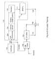
- FIG. 4is an overview of the logic of the present invention and how the invention is arrange in relation to other components of a noise and vibration reduction system;
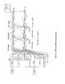
- FIG. 5illustrates a generalized neural network which forms the basis for the control system of the present invention
- FIG. 6illustrates the arrangement of an emulator neural network as the emulator is being trained to model the plant
- FIG. 7illustrates how the components of the a sensed noise and vibration preprocessing unit convert the sensed analog noise into digital form for use in controlling noise and vibration;
- FIG. 8illustrates the use of a digital Hilbert Transform Finite Impulse Response (FIR) filter to generate the envelope of the noise signal
- FIG. 9illustrates the emulator during the control mode after the emulator has been trained to model the associated plant
- FIG. 10illustrates a reference signal generator and describes the type of signals generated by the preferred embodiment of the reference signal generator
- FIG. 11illustrates the controller neural network during the control mode
- FIG. 12illustrates the use of a single control signal to control multiple devices which alter the flow of fluid over a surface.
- FIG. 1there is shown a system for controlling the noise and vibration generated by the rotors of a helicopter similar to that disclosed in the Charles U.S. Pat. No. 5,588,800 patent.
- the helicopter 40has a number of rotors blades 42 , each with a trailing edge flap 44 .
- the flaps 44can be actuated so as to result in increases and decreases in the lift of the blade as the blade rotates around its drive shaft 46 .
- the actuations of the flapsare timed so as to reduce the overall noise and vibration of the system.
- Noise sensors 48 in the form of pressure transducers mounted on at least one blade and vibration sensors 49 in the form of accelerometers mounted within the cabin 50measure the effectiveness of the reduction efforts.
- the various sensors 48 and 49deliver their error signals through connections 51 and 52 to a control system 53 which then controls the positions of the flaps 44 through a control channel 54 so as to minimize the noise and vibration generated by the blades of the helicopter.
- the term “plant”is used to refer to the assemblage of the rotor blades 42 , an actuator 55 , a hydraulic line linkage 56 , the flaps 44 , and the noise and vibration sensors 48 and 49 .
- the instantaneous angular position of each rotor bladeis calculated as it rotates with drive shaft 46 .
- Noise and vibration productionis related to the instantaneous angular position of each blade. Therefore, the instantaneous angular position of the blade is a parameter measured independently of the noise and vibration and is used during the training of the neural net emulator and also in the control mode to provide additional input information to the net to allow estimation of noise and vibration as a function of blade azimuth position. Therefore, the flap 44 actuations occur while the rotor blade is traveling through predetermined regions of the rotor blade's path in order to minimize the noise and vibration generated by the blade in that angular position. Furthermore, additional flight input signals, such as the helicopter forward speed and payload, can also be used to provide flight condition information during the training and learning period of the neural net emulator and controller. As used in this application, the term payload indicates the total weight, including passengers and cargo. These input signal(s) allow the emulator and controller to operate over a wider flight regime.
- the emulatoruses the input flight condition signal(s), the blade position and the flap control signal to effectively estimate the noise and vibration at different flight conditions, thus reducing the time required for re-training the emulator at each operational point in the flight regime.
- the controllercan also use the flight condition signals to retrieve a previously calculated flap control solution and initialize the control algorithm to provide a quick convergence to the optimum solution since the previous (initial) estimate of the flap control is close to the optimum solution.
- This retrievalcould be done from any type of computer based storage medium such as disk drives, tapes or memory chips.
- the retrievalcould also be performed by executing an algorithm developed to provide the optimum solution based on input parameters. Note that the aerodynamic-altering effect achieved by actuating the flaps 44 could also instead be achieved by twisting the blades 42 around their longitudinal axes such as the axis 57 elastically or in a rigid manner.
- FIG. 2there is shown a system for controlling the noise and vibration generated by the undesired interaction of two of the four propeller screws of a ship.
- the shiphaving a hull 60 , has two screw propellers 62 and 64 on each side each with fixed pitch or variable-pitch propeller blades 66 and 68 .
- Part of the wash or turbulent wake of the forward propeller 62will, at least at some speed, strike the blades 68 of the aft propeller 64 .
- That wash or wake from the forward propellercan interact with the blades of the aft propeller 64 to generate vibration which can be transferred to the bearings (not shown) of the shaft 69 of the aft propeller. Damage can be done to those shaft bearings, and the vibration can be transferred to the ship's hull 60 .
- the blade pitch of at least the second or aft-most of the two propellers 64can be altered so as to change the flow of water flowing over that aft propeller 68 .
- the angular position of the drive shaft 67 of the forward propeller 62can be measured and used to estimate the fluctuations in fluid flow over the aft propeller 64 which result from the wash of the forward propeller 62 .
- the pitch alterations of aft propeller 64are timed so as to reduce noise-and-vibration-producing effect that the wake or wash of the first or forward propeller 62 has on the aft propeller 64 .
- the angular position and pitch of the blades 66 of the first propeller 62can also be used as indicative input parameters measured independently of the noise and vibration.
- the speed of the ship through the wateralso effects the noise and vibration generated by both propellers and is a parameter measured independently.
- the plantis defined as the propellers 62 and 64 , the blades 66 and 68 , a hydraulic line linkage (not shown) necessary to drive the pitch variations, the noise 70 and vibration sensors 71 .
- FIG. 3there is shown a system for controlling the noise and vibration generated in the tail of an airplane as the wake of the airplane's propellers flows over an elevator surface of the airplane.
- the airplane 80has one or more propellers 82 with a plurality of blades 84 .
- the rotational angular position of the propeller blades 84can be measured so as to estimate the resultant airflow wake that will travel in time over the horizontal stabilizer 86 and elevator surfaces 94 .
- the elevator surfacehas at least one trim tab 88 which can be altered.
- the alterations of the trim tabs 88are timed so as to correspond with and cancel out the noise and vibration generated by the pulsation of prop wash as those pulsation reach the elevator surface 94 after being generated by the propeller 82 .
- Noise sensors 90are mounted on the elevator and vibration sensors 92 are mounted within the airplane 80 to measure the effectiveness of the reduction efforts.
- the angular position of the propeller 84 and the speed of the airplaneare parameters that are measured independently of the generated noise and vibration.
- the plantis defined as the propeller 82 , the propeller blades 84 , the hydraulic or mechanical line linkage 93 necessary to drive the trim tabs 88 and the noise 90 and vibration 92 sensors.
- a controller 95receives the noise sensor signals 90 on connection 89 and the vibration sensor signals 92 on connection 91 as well as propeller positions and airspeed inputs to control the instantaneous position of the trim tabs 88 .
- FIG. 4there is shown a block diagram of how a control system 100 is arranged in relation to the other portions of an active, adaptive vibration and noise attenuation system (AAVNAS).
- the control system 100is based on two neural networks: an emulator neural network (emulator) 102 and a controller neural network (controller) 104 .
- Additional devicesfacilitate transferring inputs and outputs to and from the emulator 102 and controller 104 including: a reference signal generator (RSG) 106 , time-based filter elements 108 and 109 for the inputs to the emulator and controller, a sensed noise and vibration preprocessing unit (SNVPU) 110 , and a summing unit 112 .
- RSGreference signal generator
- SNVPUsensed noise and vibration preprocessing unit
- summing unit 112a summing unit 112 .
- Inputs to the control system 100include the sensed noised and vibration signals flowing on connection 114 from one or more noise and vibration sensors 115 as well as one or more parameters received from a parameter sensor(s) 126 which sense the noise-independent parameter, e.g. angular position of a rotor blade (as measured by the sine and cosine of the angle relative to some reference point on the rotor shaft) received on connections 120 , 121 , and forward velocity of the vehicle received on connection 119 (vehicle operation-condition input signal), which are measured independently of the noise and vibration and which are at least partially indicative (predictive) of the noise and vibration.
- the outputs of the parameter sensor(s) 126are furnished on connections 119 , 120 , and 121 .
- the control systemgenerates an output control signal flowing on a connection 122 , which is used to drive a flap or other altering-device 124 so as to change the generated and thus sensed noise and vibration received on connection 114 from the sensors 115 , and is also used as one of the inputs to the emulator time-based filter 108 for estimating the plant noise and vibration using the emulator.
- the matrix coefficients of the neural net controller 104are initialized with small random values, and the matrix coefficients of the emulator 102 are initialized with the pre-computed values obtained from the neural net emulator training process to model the dynamics of the plant 130 (see FIG. 6 ).
- the reference signal on connection 150 and the forward velocity signal 119are placed into a time-based filter and 109 (for example, digital tapped delay lines) at the input of the controller 104 .
- the controllerdoes a forward pass of the values stored in the time-based filter and 109 through the calculations performed on its neural network.
- This forward passcomputes the output control signal on connection 122 , which is connected to both the altering-device 124 and the input time-based filter 108 of the emulator 102 .
- the output control signalis delivered to the altering-device 124 and to the emulator time-based filter 108 during the next A/D sample clock cycle.
- New indicative parametersare received on connections 119 , 120 , and 121 (e.g. vehicle forward velocity, sine and cosine of the blade angular position), and a new reference signal is received on connection 150 .
- the signals on connections 119 , 120 , and 121are placed into the time-based filter 108 (e.g. the tapped delay lines) of the emulator 102 , and signals on connections 119 and 150 are placed into the time-based filter 109 of the controller 104 .
- the emulatordoes a forward-pass of the values placed in the input filter 108 through the fixed matrix coefficients from the emulator training process as to constitute its neural network simulation capability and produces an estimate of the noise and vibration signal on connection 134 which is sent to the summing unit 112 .
- the measured noise and vibration signals on connection 114are also processed in the sensed noise and vibration preprocessing unit (SNVPU) 110 and are delivered on connection 136 to the summing unit 112 as digitized noise envelope and vibration signals.
- SNVPUsensed noise and vibration preprocessing unit
- the differences in the sensed and estimated noise and vibration signals 138are calculated in the summing unit 112 and are used to assess, in real time, the emulator accuracy to the actual plant process and to determine whether emulator re-training is necessary (see below for options if re-training is necessary).
- the sensed digitized noise envelope and vibration signals on connection 136 from the SNVPU 110are also returned to the emulator 102 .
- the emulator 102then backpropagates these signals carried on connection 136 through its network in order to calculate the gradient of the plant error signals with respect to the input control signal received on connection 122 .
- the plant error gradientis then sent to the controller 104 on connection 140 .
- the controlleruses a gradient-based algorithm (see the Controller section below) to backpropagate the plant error gradient through its neural network and adapt its matrix coefficients in layers 3 , 2 and 1 (see Emulator in Control Mode and Controller sections).
- the controllercan now do a forward pass of the filter tapped delay line reference values 109 through its updated neural net matrix coefficients and calculate a new output control signal for the next state carried on the connection 122 .
- the emulator modeling of the actual plant processis not accurate enough (based on the differences in the sensed and estimated noise and vibration), retraining may be necessary (see Training the Emulator section below).
- the AANVASmay indicate this inaccuracy to the user such devices as warning lights or computer printouts (on a monitor, printer, or any other type of computer output device). The user can then immediately halt the plant process and reinitiate the emulator training procedure, or the user can note the need for retraining and defer the retraining procedure until a more convenient time.
- Both the emulator 102 and the controller 104have feed-forward, multi-layer architectures with input tapped delay lines 108 and 109 to capture the temporal dynamic behavior of the plant required for control of a dynamic system.
- the neural net processors(emulator 102 and controller 104 ) have three-layer architectures.
- the neural net of FIG. 5has four inputs, (indicative/predictive) parameters h 1 , h 2 , and h 3 received on a connections 199 , 200 , and 201 (e.g. forward velocity of the vehicle, sine and cosine of the main rotor angular shaft position) and an input signal y received on a connection 202 .
- the number of indicative parametersis at least one and can vary according to the particular application and should not be seen as a limitation on the present invention.
- Each indicative parameterassists the neural network in building relationships useful to model and control the nonlinear plant dynamics at different vehicle operational points.
- connection 202The nature of the input signal y received on connection 202 depends upon whether the neural net of FIG. 5 is functioning as the emulator 102 or the controller 104 . Also, the input signal y received on the connection 202 to the emulator 102 depends upon whether the emulator 102 is in its initial “plant model training” regime or is performing in its “adaptive control” regime during active control of the active, adaptive vibration and noise attenuation system (AAVNAS). The nature of these input signals, y, received on connection 202 and the “regimes” under which the neural net is being trained or used in adaptive control mode are described in more detail below.
- AAVNASadaptive vibration and noise attenuation system
- the input signal y received on connection 202 and input signals h 1 , h 2 , and h 3 received on connection 199 , 200 , and 201are stored in time-based filter elements 108 , preferably in the form of delay lines.
- These delay linesare similar to shift registers in which the current input signal is shifted in, each previously-stored input signal is shifted forward, and the input signal from N frames is shifted out where N represents the number of available storage positions in the tapped delay lines. The shifting is done at the beginning of each flame shortly after the start of the A/D clock cycle has occurred.
- These delay linesfilter the inputs to both the emulator 102 and controller 104 neural networks and provide a time-based history of N signal values.
- Each layerincludes a matrix formed by the several row vectors in that layer.
- the matrix in the first layeris formed by the row vectors w 0 (1) through W Q (1) , where the dimension of each row vector is 1 ⁇ (N 1 +N 2 +N 3 +N 4 +1) resulting in a matrix with dimensions (Q+1) ⁇ (N 1 +N 2 +N 3 +N 4 +1).
- the input signal y(n) to the first layeris delayed by N 1 ⁇ 1 samples and the forward velocity signal h 1 (n) and blade sine and cosine position signal h 2 (n) and h 3 (n) are delayed by N 2 ⁇ 1, N 3 ⁇ 1, and N 4 ⁇ 1 samples, respectively, (for example, in FIG.
- N 2 ⁇ 12 for a two-sample delay
- an input bias b 1is included to form a total input vector of dimension (N 1 +N 2 +N 3 +N 4 +1) ⁇ 1.
- This input vectoris multiplied with the matrix in the first layer (formed by row vectors w 0 (1) through W Q (1) ) resulting in the intermediary output vector yl with elements y 0 (1) through y Q (1) .
- This vectoris then multiplied element-by-element with a vector of sigmoidal functions producing the first layer output vector x 1 .
- the same processis then repeated for the second layer in which the input vector is now defined by the output of the sigmoidal functions from the first layer which are [x 0 (1) , x 1 (1) , x 2 (1) . . . x Q (1) ] and a bias b 2 .
- This vectormultiplies the matrix formed by rows w 0 (2) through w M (2) in the second layer whose dimension is (M+1) ⁇ (Q+2) where M+1 is the number of nodes in the second layer and Q+2 is the number of input channels into the second layer.
- the third layerperforms similar operations, and the output vector with elements [x 0 (3) , x 1 (3) , x 2 (3) , x L (3) ].
- the output vector with elements [x 0 (3) , x 1 (3) , x 2 (3) . . . x L (3) ]is summed with the digitized output sensor signals [sensor 0 , sensor 1 , . . . sensor L ] in summing unit 112 to produce outputs [e 0 , e 1 , . . . e L ], which constitute the outputs of the neural net.
- the processing described above and shown in FIG. 5is performed at 512 Hz, which is the sample rate of the neural net emulator and controller process.
- the sample rateis also the same as the A/D clock rate.
- Each delay z ⁇ 1is one sample interval. Therefore, in the preferred embodiment, the output of the third delay of the input signal y (stored in input filter element y(3)), is ⁇ fraction (3/512) ⁇ of a second later than the input signal y that gave rise to it.
- the first operationis to train the emulator 102 to model the plant nonlinear dynamics.
- Methods of plant identification for linear systemsare well known in the art. One example of such methods is described in U.S. Pat. No. 4,677,676, issued to Eriksson on Jun. 30, 1987 ('676 patent).
- U.S. Pat. No. 4,677,676, issued to Eriksson on Jun. 30, 1987('676 patent).
- To model a linear system at specific frequenciesonly one amplitude/phase sinusoid input is required per frequency since with different amplitudes, the output is linearly related.
- the present inventiongenerates various random samples of amplitude/phase per frequency to determine adequately the nonlinear input/output mapping at each frequency.
- Training a neural netis a process that begins with a synthesized probe signal.
- a multi-harmonic multi-pattern signalis used as the probe signal and is composed of uncorrelated patterns.
- Each patternis generated by the superposition of one or more harmonics, with the amplitudes and phases generated by random number generators; and the pattern is repeated for a number of cycles to provide adequate duration of plant excitation.
- the number of harmonicsis seven (1P-7P).
- Each pattern in the probe signalis generated by re-running the random number generators to provide an alternate set of fourteen random amplitudes and phases.
- the number of patterns required for training the neural netis based on how well the emulator can generalize with patterns not used during training.
- This probe signalis constructed in the controller 104 and is delivered on connection 222 .
- the excitation signal on connection 222is delivered through a D/A converter 224 to control the mechanism of the altering device 124 to the physical portions of the system to be controlled.
- the system under controlis operated in its customary environment, and the outputs of the plant noise and vibration sensors 115 are gathered.
- the plantreacts to the changes in the altering-device 124 created by the probe excitation signal on line 222 .
- the helicopterwould be operated at several predefined flight conditions for a specified flight regime while the flaps 44 are actuated by the excitation signal (described above), and the noise and vibration sensors record the changes that occur due to the flap actuations.
- the sensed and gathered (processed and summed) noise and vibration signalsare then related to the input excitation signal on connection 222 driving the altering-device 124 , and to the indicative parameters on connections 119 , 120 , and 121 .
- This data-collection processis done during normal operation of the system.
- the collected dataare stored by means of a mass computer storage device such as a magnetic tape or disk drive.
- the dataare then analyzed off-line to build the relationship between input and output data.
- the dataneed not be collected and then processed off-line but can be processed through the neural net in real time, thereby obviating voluminous data collection.
- the preferred embodiment of the present inventionuses the real time neural net emulator processing to build the input/output data relationship.
- FIG. 6assumes real-time processing of the sensed noise and vibration signals on connection 114 from the changes in the altering-device 124 driven with the multi-harmonic multi-pattern excitation signal on connection 222 generated in the controller 104 .
- the sensed noise and vibrations on connection 114are delivered to the SNVPU 110 which processes the sensed noise and vibration into digitized noise envelopes and vibration signals. Those signals are transferred on a connection 136 to a plurality of summing circuits 112 . This processing by the SNVPU 110 is described in greater detail below.
- the processing in the emulator 102 and controller 104is performed at 512 Hz.
- the probe signal on connection 122 and indicative (predictive) parameter signals on connections 119 , 120 , 121are also sampled at 512 Hz. These digital signals appear at the input time-based filters 108 to the emulator 102 .
- the emulator 102 of FIG. 6is in the form of the neural net circuit of FIG. 5 .
- the probe signal on connection 122 and indicative (predictive) parameter signals on connections 119 , 120 , and 121 of FIG. 6correspond to the input signal y on connection 202 and the parameter signals h 1 , h 2 , and h 3 on connections 199 , 200 and 201 , respectively, of FIG.
- the summing circuits 0 -L of FIG. 5correspond to the summing circuit 112 of FIG. 6 .
- the emulator 102 estimated noise and vibration outputs transmitted on connection 134 of FIG. 6corresponds to the output signals [x 0 (3) , x 1 (3) , x 2 (3) . . . x L (3) ] from the third layer of the neural net of FIG. 5 and is delivered as a negative input to the summing circuit 112 . Therefore, the difference between the measured noise and vibration signals [sensor 0 , sensor 1 , . . .
- the number of indicative parameter signalscould be one or more depending upon the specific application in which the AANVAS is used.
- the Haykin referenceprovides a description of neural net architectures and training.
- the Omatu, et al. referencedescribes applications of neural nets used in industrial control systems.
- the error outputs (in the form of difference signals) from the summing circuits 112 of FIG. 6are used with a backpropagation algorithm or with nonlinear optimization algorithms such as quasi-Newton, conjugate gradient or Kalman filtering techniques to adjust the multiplier coefficients of the emulator 102 until the emulator produces an estimate signal within a arbitrary error tolerance E(l) to the output of the SNVPU 110 , from the sensed noise and vibration received on connection 114 .
- E(l)to the output of the SNVPU 110
- connection 114the emulator 102 is said to have “learned” how to emulate the sensed noise and vibration received on connection 136 . In this way, the emulator 102 learns to model the intricate nonlinear and time-varying dynamics of the plant 130 from the input probe signal to the changed altering-device states through to the noise envelope and vibration signals.
- Each indicative parametershould be a value that is related to the plant noise and vibration which is being controlled at the various operational points of the vehicle.
- One advantage of the present inventionis its ability to use different indicative parameters to allow the AAVNAS to reduce noise and vibration over a variety of operating conditions using the same neural network topology.
- the forward velocity of the helicopteris one candidate indicative parameter.
- the systemcan operate without the velocity input signal at specified discrete operational points. However, at the in-between operational points, that is during transition from one operational point to the next, the system would not perform as well since the plant noise and vibration change from one operational point to the next, and the emulators are trained to predict noise and vibration only at the specified operational points.
- the neural net emulatorshould be able to retrieve the appropriate plant emulation based on the input velocity signal. In addition, for the in-between points, the neural net emulator will automatically provide the necessary interpolation. So, with this approach, there is no need to store (eight or more) emulators in memory, download the appropriate emulator or do the interpolation.
- the basic raw form of the sensed noise and vibration signalsis a large collection of values representing the intensity of the noise or vibration.
- the noise and vibrationIn order to evaluate the noise and vibrations being produced, the noise and vibration must be reduced into digital quantitative values which are then evaluated with an objective function.
- the SNVPU 110performs this reduction by isolating the noise or vibration sensed by sensors 115 at particular target frequencies and quantifying the value of the signal being sensed at each of those target frequencies.
- the SNVPU 110receives sensed noise and vibration signals in analog form on connection 114 from the sensors 115 .
- the analog sensor signals on connection 114are first digitized in the A/D converter 231 and bandpass filtered in the signal processor 232 in order to extract (i) the frequency bandwidth of the noise signature and (ii) the vibratory loads at the vibration frequencies desired to be controlled.
- Bandpass filter designis well known.
- One method of creating this filter 232is by using a software tool called Matlab produced by a company called The MathWorks, Inc., 24 Prime Park Way, Natick, Mass. 01760-1500 (508) 647-7000.
- this filteris a digital infinite impulse response (IIR) implemented in software on a DSP (digital signal processor).
- IIRdigital infinite impulse response
- the digital vibration signalsare sampled at the execution rate of the controller and emulator (in the preferred embodiment this rate is 512 Hz) and are bandpass filtered in signal processor 232 as previously described to generate the desired vibratory loads.
- the bandpass filtered vibration signals obtained from multiple cabin locationsare then transmitted to the summing circuit 112 on connection 136 .
- the digital noise signals to be controlledare highly variable and are sampled at a rate higher than the execution rate of the controller and emulator. In the preferred embodiment, this digital noise signal sample rate is 2560 Hz.
- the noise signalsare transformed to baseband frequencies using a Hilbert Transform digital envelope detector. The controller is then used to reduce the BVI noise envelope signals rather than the highly variable noise signals, thus reducing the overall DSP computational requirement.
- the digital noise signalsare first bandpass filtered in signal processor 232 to pass only the BVI frequency band signature. The signals that exit the bandpass filter are then analyzed in a Hilbert Transform envelope detector filter 234 to identify the envelope of the noise signal loci. Noise sensor signals at multiple locations on the blade are processed through the envelope detector, and the resulting noise envelope signals are then transmitted on the connection 136 to the summing circuit 112 .
- Identifying a signal envelopeis conceptually like detecting an AM radio signal, but with digital data signals.
- the block diagram in FIG. 8describes the Hilbert Transform envelope detector.
- the upper pathgenerates the Hilbert Transform of the input noise signal (.i.e., xhat) by filtering the input noise through a FIR (Finite Impulse Response) Hilbert Transform digital filter.
- FIRFinite Impulse Response
- the FIR Hilbert Transformeradds a delay of (K ⁇ 1)/2 taps (K is the FIR filter length).
- Kis the FIR filter length.
- the lower path of the block diagramcompensates for this delay by introducing a pure delay of (K ⁇ 1)/2 to the input noise signal.
- the noise envelope signalis then generated by taking the square root of the noise power obtained by summing the power of the Hilbert transformed signal and the original delayed signal (i.e., sqrt(x ⁇ circumflex over ( ) ⁇ 2+xhat ⁇ circumflex over ( ) ⁇ 2)).
- the envelope of the noise signal on connection 135is then lowpass filtered and decimated, since the baseband signal envelope in the preferred embodiment has a narrow frequency bandwidth in relation to the sample rate of the A/D converter, and delivered on connection 136 to the summing circuit 112 .
- the AID sample rate for the input noise signalsis at 2560 Hz and the processed noise envelope signals are decimated or reduced in numbers by a factor of five down to the 512 Hz sample rate processing of the neural net emulator and controller.
- noise and vibration sensorsthere are a plurality of noise and vibration sensors.
- the sensorsthere is one or more of the combination of IIR and FIR filters which isolate the noise or vibration being transmitted at the desired frequency bands and quantify the value of the signal being transmitted.
- the quantified valueis then analyzed against the estimated noise and vibration values from the emulator 102 to determine the error in the plant model.
- This objective functionis the quantified summation of the actual sensed noise envelope and vibration signals desired to be reduced or suppressed.
- the objective functionrepresents a “strength” measurement of the objectionable noise and vibration and, as such, is one possible criterion by which the efficacy of the control efforts is judged.
- One skilled in the artcould easily derive other criteria related to the reduction of noise and vibration by which to judge the efficacy of the control efforts.
- the AAVNAShas necessarily reduced the objectionable noise and vibration.
- the emulator training modethe emulator is trained to generate an output that is an estimated value representing the results of the vibration and noise envelope signals.
- the controller 104is adapted to produce control signals to the altering-device to minimize the objective function value calculated from the noise and vibration signals that occur after the altering-device has been changed via the control signals.
- that objective functionhas the exemplary form of:
- Fx, Fy, Fz, Mx, and Myare the digital vibration measurements at the desired frequency (i.e., 4P for helicopter fixed frame hub loads).
- vibration measurementscomprises the readings from accelerometers mounted in the cabin of a helicopter measuring the cabin forces and moments.
- P 1 and P 2are noise envelope measurements.
- noise measurementscomprises the readings from pressure transducers mounted on the rotor blade of a helicopter.
- k 1 -k 7 , and a 1 -a 2are weighting coefficients which allow the active, adaptive vibration and noise attenuation system (AAVNAS) to emphasize certain components more than others (i.e., k 1 -k 7 ) and also emphasize more the vibration or noise objective function (a 1 , a 2 ).
- AAVNASactive, adaptive vibration and noise attenuation system
- FIG. 9there is shown a block diagram of the emulator 102 during the control mode (after the plant model training has occurred) in the preferred three-layer embodiment.
- the emulator 102is not adaptive; and the emulator weighting coefficients stored in the row vectors 300 are fixed.
- the output control signal u(n) received on connection 122corresponds to the y input signal received on connection 202 in FIG. 5; and the (indicative/predictive) parameter signals (e.g. the forward velocity and the sine and cosine of the rotor shaft angular position) received on connections 119 , 120 , and 121 correspond to the h 1 , h 2 and h 3 references received on connection 199 , 200 , and 201 in FIG. 5 .
- These inputsgo through tapped delay lines 108 .
- the input vectorcontains all of the delayed values stored in the time-based filter 108 .
- an alternate embodimentwould be to compose the input vector from selected values stored in the time-based filter 108 .
- the input vectoris processed in a forward direction (“forward pass”) through the fixed row vectors 300 of the emulator 102 producing the sigmoidal function output vectors on a layer-by-layer basis at the first layer x 1 stored in memory location 310 , second layer x 2 stored in memory location 312 , and third layer x 3 stored in memory location 314 .
- these outputsare stored in memory locations 310 and 312 and 314 and are used during the backpropagation of sensor signals [sensor 0 , sensor 1 , sensor 2 , . . .
- the weight w q,m (2)is the ‘q ⁇ m’ coefficient that relates the q'th input from the first layer to the m'th neuron in the second layer
- w m,l (3)is the ‘m ⁇ l’ coefficient that relates the m'th input from the second layer to the l'th neuron in the third layer
- These signals x k (i)are computed and stored in column vectors x 1 , x 2 and x 3 at location 310 , 312 and 314 during the forward pass through the emulator, and are used during the reverse pass to compute the reverse pass gradients.
- the reverse passstarts with the backpropagation of the sensor signals on connection 136 in the third layer to compute the gradient at the output of the emulator using equation (7), this allows the gradient computation to be determined at the second layer using equation (6), at the first layer using equation (5) and then equation (4) determines the instantaneous plant gradient with respect to the j'th input control signal in the delay line.
- This gradientis then delivered on connection 140 to the controller 104 to allow the adaptation of the neural net controller matrix coefficients using a temporal backpropagation gradient algorithm (see Controller section, below).
- the estimated noise envelopes and vibration signals stored in memory location 314are negated and added to the digitized sensed noise envelopes and vibration signals [sensor 0 , sensor 1 , sensor 2 . . . sensor L ] on connection 136 to verify that the emulator (fixed coefficients) produces an estimate signal within an arbitrary error tolerance E(l) on connection 138 , thus making it valid to use the data stored in memory locations 310 , 312 and 314 for backpropagation of the error sensors to generate the plant gradient using equation (4).
- FIG. 10illustrates how the angular rotor position is used to create the input reference signal to the neural net controller.
- the reference signal generator 106uses the angular position of the rotor to create sinusoids of harmonics of rotor frequency P.
- the angular position of the rotoris transmitted from a measuring device 240 , (e.g., a sensor connected to the rotor on a helicopter to measure the rotor position) on connection 242 .
- a measuring device 240e.g., a sensor connected to the rotor on a helicopter to measure the rotor position
- a measuring device 240e.g., a sensor connected to the rotor on a helicopter to measure the rotor position
- a measuring device 240e.g., a sensor connected to the rotor on a helicopter to measure the rotor position
- a measuring device 240e.g., a sensor connected to the rotor on a helicopter to measure the rotor position
- the diskhas differing reflective properties such as white stripes extending radially from the center.
- the light sensordetects the differences in the photoelectric disk and uses these differences to calculate an angular position.
- Another example of such a sensoris a starwheel with an associated magnetic sensor, as used in the distributors of new automobiles.
- the starwheelhas one or more teeth along the outside edge. As the starwheel rotates, the teeth pass close to one or more fixed magnetic sensors which detect a change in a magnetic field. This change can then be used to calculate angular position.
- the reference signal transmitted on connection 150is a time series sinusoidal signal based on a combination of one or more harmonics of P, with P being measured for the sound producing system.
- weighting factorsmay be included to give a different weight to the various harmonics in the resulting output wave.
- the reference signalis a time-sampled combination of the 2P and 3P harmonics (for the helicopter reference) as represented by the following equation:
- the TWOPWEIGHT factoris 0.8 and the THREEPWEIGHT factor is 0.2.
- the reference signal generator (RSG) unit 106 in FIG. 10illustrates the reference waveform that would be created by summing a 2P and 3P harmonic wave. Reference signals for other embodiments would be generated in a similar fashion.
- the v 1 (n) values received on connection 202are the reference signals generated by the reference signal generator 106 described in connection with FIG. 10 which, in the preferred embodiment of the present invention, comprises a combination of sinusoids of a base reference rate delivered on connection 150 .
- the hv 2 (n) signal received on connection 199is the forward velocity of the vehicle indicative of the operating condition and delivered on connection 119 .
- the hv 2 (n) vectormay be null. Whether the hv 2 (n) vector is null or populated depends on which indicative parameters are selected for the particular embodiment of the AAVNAS.
- Connections 150 and 119 describing the input to the controller 104are the same connections with connection 202 and 199 describing the input to the generic neural network.
- the input vector v(n)contains all of the delayed values stored in the time-based filter 109 .
- an alternate embodimentwould be to compose the input vector from selected values stored in the time-based filter and 109 .
- the controller 104does a forward pass of the time-based filter reference vector v(n) through its neural net matrix coefficients to generate the output control signal u(n) on connection 122 which is composed of a combination of phase and amplitude shifted harmonics of the base reference rate P.
- the reference signalcontains possibly 2P and 3P frequencies
- the nonlinear sigmoidal functions in the neural net controllercan model higher order harmonics that may be present in the error signals.
- the neural netgenerates a control signal that contains a combination of the 2P, 3P, 4P, and 5P harmonics for the reduction of vibration and noise in reference to the helicopter application determined from digital closed loop simulations of the neural network and math models of the blade-flap BVI noise dynamics.
- the preferred embodiment of the controllerhas three layers with the third layer comprising a single element (neuron) because the controller only transmits a single control signal on connection 122 to be used by the altering-device 124 (see Use of the Control Signal section, below) and also to be used as an input into the time-based filter 108 of the emulator 102 . While data are progressing in a forward direction through the several layers of the controller 104 (forward pass of the reference signal), the intermediate results from the input, first and second layer are stored in memory locations to be used during the backpropagation of the gradients calculated by the emulator 102 that occurs during the reverse pass.
- the third layercomprising a single element (neuron) because the controller only transmits a single control signal on connection 122 to be used by the altering-device 124 (see Use of the Control Signal section, below) and also to be used as an input into the time-based filter 108 of the emulator 102 . While data are progressing in a forward direction through the several layers of the controller 104 (forward pass of
- the input reference column vector and delayed copies ⁇ v(n),v(n-1), . . . v(n ⁇ j), . . . ⁇are stored in memory location 315
- the first layer output column vector and delayed copies ⁇ x 1 c(n),x 1 c(n ⁇ 1), . . . x 1 c(n ⁇ j), . . . ⁇are stored in memory location 320
- the output signal on connection 122represents the results stored in location 324 and drives an altering-device 124 (see also FIG. 4 and the associated description) to minimize the fluid flow disruptions which result in the sensed noise and vibration.
- the output control signal on connection 122is an input to the time-based filter 108 of the emulator 102 , which is used in the emulator's plant model for estimating noise and vibration and for computing the gradient of the objective function with respect to the plant input.
- the controller 104waits for the emulator 102 to return the instantaneous gradient of the objective function on connection 140 .
- the preprocessed sensed noise and vibration signals from unit 110are received by the emulator on connection 136 (FIG. 9) and are then backpropagated through the emulator 102 to generate the instantaneous gradient of the objective function with respect to the j'th control input signal u(n ⁇ j) (equation (4)).
- This gradientis received by the controller and is then backpropagated through the controller network using a temporal backpropagation algorithm for FIR neural networks (“Temporal Backpropagation for FIR Neural Networks”, Wan E. A., 1190, IEEE International Joint Conference on Neural Networks, San Diego Calif.) since the controller and emulator are separated by the tapped delay line.
- w (3c)is the row vector in the third layer of the neural net controller
- ⁇is the convergence parameter of the gradient algorithm and can be made adaptive as specified in the Haykin reference via the delta-bar-delta learning rule
- ⁇ J ⁇ y ( 3 ⁇ c ) ⁇ ( n - j ) ⁇ ⁇ ( 3 ⁇ c ) ⁇ ( n - j )⁇ ′ ⁇ ( y ( 3 ⁇ c ) ⁇ ( n - j ) ) ⁇ ⁇ J ⁇ u ⁇ ( n - j ) ( 10 )
- the input and first layer column vectors and delayed copiesi.e., ⁇ fv(n),v(n ⁇ 1), . . . v(n ⁇ j), . . . , x 1 c(n), x 1 c(n ⁇ 1), . . . x 1 c(n ⁇ j), . . . ⁇ previously stored in memory locations 315 / 320 , and ⁇ x 2 c(n),x 2 c(n ⁇ 1), . . . ,x 2 c(n ⁇ j), . . . ⁇ from the second layer stored in memory location 322, are now used in the update rules of equations 9-12.
- the controller matrix coefficientsare then modified in real time according to equations 9-12.
- the controllerAfter the controller matrix coefficients have been updated, the controller does a forward pass of the time-based filter reference vector v(n) through its updated neural net matrix coefficients and calculates a new output control signal on connection 122 .
- the control signaldrives the altering device 124 to reduce the noise and vibration and also drives the emulator 102 to compute a new plant gradient for the next state. A complete elimination of the noise and vibration is not always achievable.
- the controlleradapts its matrix coefficients during each state to determine the optimum control solution that will drive the plant to generate the minimal noise possible under the current operating conditions.
- the initial weights of the controllercan be set to optimum values which can be either pre-computed from an off-line digital simulator, or computed and stored in computer memory-based on a previous operation of the vehicle.
- the digital simulatorconsists of the neural net controller configured to reduce the output of the neural net emulator which models the plant noise and vibration output signals.
- the neural net controlleradapts its coefficients to reduce the emulator equivalent plant noise and vibration outputs. The converged set of controller matrix coefficients from the simulation can then be used to initialize the real time controller.
- the real time controller matrix coefficientsare set to small random values, and the controller training at the operational points in the specified operation regime takes place in real time.
- the initial valueshave been determined to affect the controller's performance relative to the function of produced noise and vibration. Initial non-random values can result in the controller getting stuck at local minima in the produced noise function, thus halting the move toward the global solution. Random initial values are more likely to avoid the pitfall of local minima in the vibration and noise function.
- the controllerhas been trained and tested at various operational points for the specified flight regime.
- a control solution for each operational point in the flight regimeis now stored in the computer memory and can be accessed to initialize the controller for the next flight operation using the forward velocity as the indicator in selecting the appropriate flap control solution. Therefore, during the next flight operation, the controller will initialize itself in real time with the closest optimum solution computed in the previous flight, using the current flight condition input signal.
- This approachis realizable since neural nets have an inherent capability of interpolation; and even though the operational point may be slightly different from the previous flight, the neural net controller will interpolate to provide the best starting point solution. Since this starting solution is close to the optimum, the controller will quickly converge to the optimum solution.
- the number of neurons in each layeris dependent on external factors.
- the last (third in the preferred embodiment of the present invention) layercomprises a single neuron because only one control output is produced by the controller.
- the number of neurons in the first, second and any subsequent intermediate layersrepresents a tradeoff between two competing factors.
- the first factoris computational resources, i.e. the amount of computer time available to execute the algorithm. Each neuron added increases the amount of calculation necessary to generate a control signal.
- the second factoris controller performance in noise and vibration reduction. More neurons increases the ability of the controller to generate control signals giving better noise and vibration reduction. After a certain number of neurons (which depends on the complexity of the plant being modeled), additional neurons result in only marginal performance improvements. Available computational resources are balanced against the marginal performance improvements when determining whether to add another neuron to the neural net first and second layers.
- FIG. 12there is shown a system for using one control signal to control multiple altering-devices.
- multiple surfacesexist over which the fluid is flowing and producing noise and vibration.
- the surfacesare all following the same path and encountering the same conditions.
- a separate controller for each bladewould be unnecessarily redundant. Instead, a control signal on connection 122 is calculated for one of the blades and then delayed for appropriate time periods before being sent to each of the other blades, in turn.
- the delayed signalsare delivered to the altering-devices on connections 360 , 362 , and 364 respectively after the appropriate time delay, (i.e., at time T/4, the signal generated by the controller is delivered on connection 360 to second altering-device 354 , at time T/2, the signal generated by the controller is delivered on connection 362 to third altering-device 356 and at time 3/4T, the signal generated by the controller is delivered on connection 364 to fourth altering-device 358 ).
- the bladesare connected to a mount 370 which is connected to the helicopter body 380 . Note that all blades fly the same around the path, and therefore all the altering-devices (i.e. flaps or propeller blades) should also follow the same prescribed trajectory at each point in the rotation of the rotor.
- blade flap slavingwas based on the blade tracking requirement imposed on the control system. Blade tracking implies that all blades must fly the same around the azimuth. To achieve the blade tracking, the algorithm was constrained by slaving the blade-flaps to a master blade-flap. It should be noted that slaving is not an invention but rather a requirement on the control system, and also is not required to insure minimum vibration.
- An alternate procedureis to have a control system whose dimension is the rank of control space for one blade multiplied by the number of blades, i.e. each flap's motion can differ in ways other than a simple time delay. Vibration and Noise reduction and other constraints such as helicopter blade tracking can then be imposed through the objective function of the control system. This increases the number of degrees that are controlled. It is a general principle that if the number of controllable degrees of freedom available to the controller are increased, then the optimum achieved is a better optimum.
Landscapes
- Engineering & Computer Science (AREA)
- Physics & Mathematics (AREA)
- Acoustics & Sound (AREA)
- General Engineering & Computer Science (AREA)
- Multimedia (AREA)
- Aviation & Aerospace Engineering (AREA)
- Mechanical Engineering (AREA)
- Feedback Control In General (AREA)
Abstract
Description


Claims (49)
Priority Applications (4)
| Application Number | Priority Date | Filing Date | Title |
|---|---|---|---|
| US09/752,180US6493689B2 (en) | 2000-12-29 | 2000-12-29 | Neural net controller for noise and vibration reduction |
| AU2002246750AAU2002246750A1 (en) | 2000-12-29 | 2001-12-28 | Neural net controller for noise and vibration reduction |
| PCT/US2001/049579WO2002059497A2 (en) | 2000-12-29 | 2001-12-28 | Neural net controller for noise and vibration reduction |
| US10/287,963US6751602B2 (en) | 2000-12-29 | 2002-11-05 | Neural net controller for noise and vibration reduction |
Applications Claiming Priority (1)
| Application Number | Priority Date | Filing Date | Title |
|---|---|---|---|
| US09/752,180US6493689B2 (en) | 2000-12-29 | 2000-12-29 | Neural net controller for noise and vibration reduction |
Related Child Applications (1)
| Application Number | Title | Priority Date | Filing Date |
|---|---|---|---|
| US10/287,963DivisionUS6751602B2 (en) | 2000-12-29 | 2002-11-05 | Neural net controller for noise and vibration reduction |
Publications (2)
| Publication Number | Publication Date |
|---|---|
| US20020117579A1 US20020117579A1 (en) | 2002-08-29 |
| US6493689B2true US6493689B2 (en) | 2002-12-10 |
Family
ID=25025231
Family Applications (2)
| Application Number | Title | Priority Date | Filing Date |
|---|---|---|---|
| US09/752,180Expired - LifetimeUS6493689B2 (en) | 2000-12-29 | 2000-12-29 | Neural net controller for noise and vibration reduction |
| US10/287,963Expired - Fee RelatedUS6751602B2 (en) | 2000-12-29 | 2002-11-05 | Neural net controller for noise and vibration reduction |
Family Applications After (1)
| Application Number | Title | Priority Date | Filing Date |
|---|---|---|---|
| US10/287,963Expired - Fee RelatedUS6751602B2 (en) | 2000-12-29 | 2002-11-05 | Neural net controller for noise and vibration reduction |
Country Status (3)
| Country | Link |
|---|---|
| US (2) | US6493689B2 (en) |
| AU (1) | AU2002246750A1 (en) |
| WO (1) | WO2002059497A2 (en) |
Cited By (65)
| Publication number | Priority date | Publication date | Assignee | Title |
|---|---|---|---|---|
| US20020118844A1 (en)* | 2001-02-27 | 2002-08-29 | Welsh William Arthur | System for computationally efficient active control of tonal sound or vibration |
| US6598480B2 (en)* | 2001-09-17 | 2003-07-29 | Hitachi, Ltd. | Vibration testing system |
| US6665633B2 (en)* | 2000-12-29 | 2003-12-16 | Seagate Technology Llc | Relation of rotational vibration stimuli to performance of a hard disc drive |
| US20030230205A1 (en)* | 2002-04-17 | 2003-12-18 | Heidelberger Druckmaschinen Ag | Compensation of cylinder vibration in printing material processing machines |
| US20040068349A1 (en)* | 2002-10-07 | 2004-04-08 | Huageng Luo | Method and apparatus for rotary machine vibration control |
| US6751602B2 (en)* | 2000-12-29 | 2004-06-15 | General Dynamics Advanced Information Systems, Inc. | Neural net controller for noise and vibration reduction |
| US20040172187A1 (en)* | 2003-02-28 | 2004-09-02 | Wiseman Matthew William | Methods and apparatus for assessing gas turbine engine damage |
| US20050116094A1 (en)* | 2003-11-27 | 2005-06-02 | Airbus France | Method making it possible to prevent vibration of a rudder of an aircraft and aircraft using this method |
| US20060058927A1 (en)* | 2004-06-10 | 2006-03-16 | Aubourg Pierre A | Method of adjusting at least one defective rotor of a rotorcraft |
| US7046180B2 (en) | 2004-04-21 | 2006-05-16 | Rosemount Inc. | Analog-to-digital converter with range error detection |
| US20060200344A1 (en)* | 2005-03-07 | 2006-09-07 | Kosek Daniel A | Audio spectral noise reduction method and apparatus |
| US20060212139A1 (en)* | 2005-02-28 | 2006-09-21 | Hedtke Robert C | Process connection for process diagnostics |
| US20070005219A1 (en)* | 2004-06-25 | 2007-01-04 | Honda Motor Co., Ltd. | System for monitoring sensor outputs of a gas turbine engine |
| US20070094173A1 (en)* | 2005-09-26 | 2007-04-26 | Harrison Gregory A | Method and System of Monitoring and Prognostics |
| US7254518B2 (en) | 1996-03-28 | 2007-08-07 | Rosemount Inc. | Pressure transmitter with diagnostics |
| US7321846B1 (en) | 2006-10-05 | 2008-01-22 | Rosemount Inc. | Two-wire process control loop diagnostics |
| US20080147251A1 (en)* | 2006-12-19 | 2008-06-19 | Jia Luo | Multi-axis trim processing |
| US7523667B2 (en) | 2003-12-23 | 2009-04-28 | Rosemount Inc. | Diagnostics of impulse piping in an industrial process |
| CN100487616C (en)* | 2003-09-30 | 2009-05-13 | 罗斯蒙德公司 | Process device with vibration-based diagnostics |
| US20090226303A1 (en)* | 2008-03-05 | 2009-09-10 | Grabowski Zbigniew M | Variable area fan nozzle fan flutter management system |
| US7590511B2 (en) | 2007-09-25 | 2009-09-15 | Rosemount Inc. | Field device for digital process control loop diagnostics |
| US20090268340A1 (en)* | 2008-04-28 | 2009-10-29 | Seagate Technology Llc | Regulating tuning rate of adaptive filter coefficients for feed-forward disturbance rejection in a servo control loop |
| US7623932B2 (en) | 1996-03-28 | 2009-11-24 | Fisher-Rosemount Systems, Inc. | Rule set for root cause diagnostics |
| US7630861B2 (en) | 1996-03-28 | 2009-12-08 | Rosemount Inc. | Dedicated process diagnostic device |
| US20100129215A1 (en)* | 2008-11-21 | 2010-05-27 | Preus Robert W | System for providing dynamic pitch control in a wind turbine |
| US7750642B2 (en) | 2006-09-29 | 2010-07-06 | Rosemount Inc. | Magnetic flowmeter with verification |
| US7913566B2 (en) | 2006-05-23 | 2011-03-29 | Rosemount Inc. | Industrial process device utilizing magnetic induction |
| US7940189B2 (en) | 2005-09-29 | 2011-05-10 | Rosemount Inc. | Leak detector for process valve |
| US7949495B2 (en) | 1996-03-28 | 2011-05-24 | Rosemount, Inc. | Process variable transmitter with diagnostics |
| US7953501B2 (en) | 2006-09-25 | 2011-05-31 | Fisher-Rosemount Systems, Inc. | Industrial process control loop monitor |
| US7977924B2 (en) | 2008-11-03 | 2011-07-12 | Rosemount Inc. | Industrial process power scavenging device and method of deriving process device power from an industrial process |
| US8112565B2 (en) | 2005-06-08 | 2012-02-07 | Fisher-Rosemount Systems, Inc. | Multi-protocol field device interface with automatic bus detection |
| US20120109600A1 (en)* | 2010-10-27 | 2012-05-03 | King Fahd University Of Petroleum And Minerals | Variable step-size least mean square method for estimation in adaptive networks |
| US8250924B2 (en) | 2008-04-22 | 2012-08-28 | Rosemount Inc. | Industrial process device utilizing piezoelectric transducer |
| US8290721B2 (en) | 1996-03-28 | 2012-10-16 | Rosemount Inc. | Flow measurement diagnostics |
| US8788070B2 (en) | 2006-09-26 | 2014-07-22 | Rosemount Inc. | Automatic field device service adviser |
| US8898036B2 (en) | 2007-08-06 | 2014-11-25 | Rosemount Inc. | Process variable transmitter with acceleration sensor |
| US9027873B2 (en) | 2009-02-27 | 2015-05-12 | Textron Innovations Inc. | System and method for vibration control in a rotorcraft using an adaptive reference model algorithm |
| US9052240B2 (en) | 2012-06-29 | 2015-06-09 | Rosemount Inc. | Industrial process temperature transmitter with sensor stress diagnostics |
| US9074531B2 (en) | 2008-03-05 | 2015-07-07 | United Technologies Corporation | Variable area fan nozzle fan flutter management system |
| US9207670B2 (en) | 2011-03-21 | 2015-12-08 | Rosemount Inc. | Degrading sensor detection implemented within a transmitter |
| US9602122B2 (en) | 2012-09-28 | 2017-03-21 | Rosemount Inc. | Process variable measurement noise diagnostic |
| US20180354630A1 (en)* | 2017-06-07 | 2018-12-13 | The Boeing Company | Methods for Optimized Engine Balancing Based on Flight Data |
| US10179646B1 (en) | 2015-12-18 | 2019-01-15 | Amazon Technologies, Inc. | Reconfiguring propellers during aerial vehicle operation |
| US10287006B1 (en) | 2015-12-18 | 2019-05-14 | Amazon Technologies, Inc. | Adjustable propeller blades for sound control |
| US10370098B1 (en)* | 2015-12-18 | 2019-08-06 | Amazon Technologies, Inc. | Adjustable propeller blade with sound flaps |
| US10387298B2 (en) | 2017-04-04 | 2019-08-20 | Hailo Technologies Ltd | Artificial neural network incorporating emphasis and focus techniques |
| CN111356958A (en)* | 2017-11-23 | 2020-06-30 | 西门子股份公司 | Method, controller and computer program product for reducing oscillations in a technical system |
| US10864900B2 (en)* | 2018-10-09 | 2020-12-15 | Toyota Jidosha Kabushiki Kaisha | Control device of vehicle drive device, vehicle-mounted electronic control unit, trained model, machine learning system, method of controlling vehicle drive device, method of producing electronic control unit, and output parameter calculation device |
| US10997962B2 (en)* | 2019-08-26 | 2021-05-04 | Lg Electronics Inc. | Apparatus and method for synthesizing engine sound |
| US11221929B1 (en) | 2020-09-29 | 2022-01-11 | Hailo Technologies Ltd. | Data stream fault detection mechanism in an artificial neural network processor |
| US11237894B1 (en) | 2020-09-29 | 2022-02-01 | Hailo Technologies Ltd. | Layer control unit instruction addressing safety mechanism in an artificial neural network processor |
| US11238334B2 (en) | 2017-04-04 | 2022-02-01 | Hailo Technologies Ltd. | System and method of input alignment for efficient vector operations in an artificial neural network |
| US11263077B1 (en) | 2020-09-29 | 2022-03-01 | Hailo Technologies Ltd. | Neural network intermediate results safety mechanism in an artificial neural network processor |
| US20220148347A1 (en)* | 2020-11-10 | 2022-05-12 | Toyota Jidosha Kabushiki Kaisha | Vehicle noise inspection apparatus |
| US20220155783A1 (en)* | 2020-11-18 | 2022-05-19 | Dus Operating Inc. | Use of neural networks in control systems |
| US11417306B2 (en) | 2020-12-31 | 2022-08-16 | Bose Corporation | Systems and methods for engine harmonic cancellation |
| US11544545B2 (en) | 2017-04-04 | 2023-01-03 | Hailo Technologies Ltd. | Structured activation based sparsity in an artificial neural network |
| US11551028B2 (en) | 2017-04-04 | 2023-01-10 | Hailo Technologies Ltd. | Structured weight based sparsity in an artificial neural network |
| US11615297B2 (en) | 2017-04-04 | 2023-03-28 | Hailo Technologies Ltd. | Structured weight based sparsity in an artificial neural network compiler |
| US11721313B2 (en) | 2020-02-25 | 2023-08-08 | Bose Corporation | Narrowband cancellation |
| US11811421B2 (en) | 2020-09-29 | 2023-11-07 | Hailo Technologies Ltd. | Weights safety mechanism in an artificial neural network processor |
| US11874900B2 (en) | 2020-09-29 | 2024-01-16 | Hailo Technologies Ltd. | Cluster interlayer safety mechanism in an artificial neural network processor |
| US12248367B2 (en) | 2020-09-29 | 2025-03-11 | Hailo Technologies Ltd. | Software defined redundant allocation safety mechanism in an artificial neural network processor |
| US12430543B2 (en) | 2017-04-04 | 2025-09-30 | Hailo Technologies Ltd. | Structured sparsity guided training in an artificial neural network |
Families Citing this family (71)
| Publication number | Priority date | Publication date | Assignee | Title |
|---|---|---|---|---|
| US6453308B1 (en)* | 1997-10-01 | 2002-09-17 | Aspen Technology, Inc. | Non-linear dynamic predictive device |
| US6994261B2 (en)* | 2000-08-10 | 2006-02-07 | Novo Nirdisk A/S | Support for a cartridge for transferring an electronically readable item of information from the cartridge to an electronic circuit |
| DE60126782T2 (en) | 2000-08-10 | 2007-12-06 | Novo Nordisk A/S | DEVICE FOR ADMINISTERING MEDICAMENTS WITH A CASSETTE HOLDER |
| WO2002087083A1 (en)* | 2001-04-18 | 2002-10-31 | The Charles Stark Draper Laboratory, Inc. | Digital method and system for determining the instantaneous phase and amplitude of a vibratory accelerometer and other sensors |
| CA2458919A1 (en)* | 2001-08-31 | 2003-03-13 | Optimum Power Technology, L.P. | Design optimization |
| DE10236815A1 (en)* | 2002-08-10 | 2004-02-26 | Airbus Deutschland Gmbh | Method for reducing the amplitude of lateral and/or vertical oscillations of aircraft fuselage, requires redundant acceleration pick-up to determine lateral and/or vertical acceleration on engine |
| WO2004055967A1 (en)* | 2002-10-17 | 2004-07-01 | Denso Corporation | Ac rotary electric machine magnetic noise reduction method, motor control device and ac rotary electric machine using the same |
| WO2004084795A1 (en)* | 2003-03-24 | 2004-10-07 | Novo Nordisk A/S | Transparent electronic marking of a medication cartridge |
| WO2005023646A1 (en)* | 2003-08-29 | 2005-03-17 | Kawada Industries, Inc. | Helicopter bvi noise reducing method and device |
| US7765175B2 (en)* | 2003-09-18 | 2010-07-27 | Optimum Power Technology, L.P. | Optimization expert system |
| US7958801B2 (en)* | 2003-10-01 | 2011-06-14 | Sikorsky Aircraft Corporation | Harmonic force generator for an active vibration control system |
| US20060243804A1 (en)* | 2003-10-03 | 2006-11-02 | Novo Nordisk A/S | Container comprising code information elements |
| US7035718B2 (en)* | 2004-01-27 | 2006-04-25 | General Electric Company | Method and System for detecting and reducing draft tube pressure fluctuations |
| WO2006120182A1 (en) | 2005-05-10 | 2006-11-16 | Novo Nordisk A/S | Injection device comprising an optical sensor |
| EP1929248B1 (en)* | 2005-09-22 | 2015-11-11 | Novo Nordisk A/S | Device and method for contact free absolute position determination |
| US20070202823A1 (en)* | 2006-02-28 | 2007-08-30 | Honeywell International, Inc. | Neural network adaptive pulsed noise blanker |
| EP1999691B1 (en) | 2006-03-20 | 2010-08-18 | Novo Nordisk A/S | Contact free reading of cartridge identification codes |
| CN101421913B (en) | 2006-04-12 | 2012-07-18 | 诺沃-诺迪斯克有限公司 | Determination of the absolute position of movable mounted elements in drug delivery devices |
| US7818073B2 (en)* | 2006-04-20 | 2010-10-19 | Asml Netherlands B.V. | Method for obtaining improved feedforward data, a lithographic apparatus for carrying out the method and a device manufacturing method |
| BRPI0710915A2 (en)* | 2006-04-26 | 2011-09-27 | Novo Nordisk As | medication delivery device and method for determining absolute positions of a first member relative to a second member of a medication delivery device |
| US7809657B2 (en)* | 2006-07-12 | 2010-10-05 | General Electric Company | System and method for implementing a multi objective evolutionary algorithm on a programmable logic hardware device |
| US20080127734A1 (en)* | 2006-11-30 | 2008-06-05 | Van Der Merwe Gert Johannes | Vibration measurement system and gas turbine engine including the same |
| EP2125083B1 (en) | 2007-03-21 | 2013-08-21 | Novo Nordisk A/S | A medical delivery system having container recognition and container for use with the medical delivery system |
| US8240120B2 (en)* | 2007-10-25 | 2012-08-14 | United Technologies Corporation | Vibration management for gas turbine engines |
| US7486469B1 (en)* | 2007-10-31 | 2009-02-03 | Hitachi Global Storage Technologies Netherlands B.V. | Minimizing a mechanical mode excitation utilizing a generated seek trajectory |
| GB0725111D0 (en) | 2007-12-21 | 2008-01-30 | Wolfson Microelectronics Plc | Lower rate emulation |
| DE102008015832B4 (en) | 2008-03-27 | 2013-08-22 | Fresenius Medical Care Deutschland Gmbh | Method and device for monitoring a vascular access and extracorporeal blood treatment device with a device for monitoring a vascular access |
| US20090265049A1 (en)* | 2008-04-22 | 2009-10-22 | Honeywell International, Inc. | Aircraft system emissions and noise estimation mechanism |
| US7839304B2 (en)* | 2008-05-01 | 2010-11-23 | The United States Of America As Represented By The Secretary Of The Navy | Method and system for alerting aircrew to unsafe vibration levels |
| DE102008050586A1 (en)* | 2008-10-09 | 2010-05-27 | Eurocopter Deutschland Gmbh | Method for reducing blade vortex interaction noise on rotor blades of rotor of rotary wing aircraft, involves recording measuring data by sensor, and rotating rotor blades collide with blade vortices |
| ES2673294T3 (en) | 2008-11-06 | 2018-06-21 | Novo Nordisk A/S | Electronically assisted drug delivery device |
| DE102009007013A1 (en)* | 2009-01-31 | 2010-08-12 | Deutsches Zentrum für Luft- und Raumfahrt e.V. | Engine, especially CROR propulsion, for an aircraft |
| WO2010092156A1 (en) | 2009-02-13 | 2010-08-19 | Novo Nordisk A/S | Medical device and cartridge |
| RU2493659C2 (en)* | 2011-12-20 | 2013-09-20 | Федеральное государственное бюджетное образовательное учреждение высшего профессионального образования "Саратовский государственный университет им. Н.Г. Чернышевского" | Method for secure transmission of information using pulse coding |
| EP2687440B1 (en)* | 2012-07-16 | 2017-10-11 | Airbus Defence and Space GmbH | Apparatus and method for reducing, avoiding or eliminating lateral vibrations of a helicopter |
| CN103177290B (en)* | 2013-04-03 | 2017-05-03 | 大连海事大学 | An identification method of ship domain model based on online self-organizing neural network |
| US9174739B2 (en)* | 2014-01-13 | 2015-11-03 | The Boeing Company | Active vibration control system |
| RU2559401C1 (en)* | 2014-04-02 | 2015-08-10 | Федеральное государственное унитарное предприятие "Центральный научно-исследовательский институт машиностроения" (ФГУП ЦНИИмаш) | Diagnostic of aircraft service systems operating conditions |
| US10148485B2 (en)* | 2014-09-03 | 2018-12-04 | Honeywell International Inc. | Apparatus and method for on-process migration of industrial control and automation system across disparate network types |
| US20170267338A1 (en) | 2014-10-01 | 2017-09-21 | Sikorsky Aircraft Corporation | Acoustic signature variation of aircraft utilizing a clutch |
| WO2016054209A1 (en) | 2014-10-01 | 2016-04-07 | Sikorsky Aircraft Corporation | Dual rotor, rotary wing aircraft |
| CN208533653U (en) | 2014-11-03 | 2019-02-22 | 艾默生电气公司 | Food waste disposer system |
| US10745263B2 (en)* | 2015-05-28 | 2020-08-18 | Sonicu, Llc | Container fill level indication system using a machine learning algorithm |
| US10746586B2 (en) | 2015-05-28 | 2020-08-18 | Sonicu, Llc | Tank-in-tank container fill level indicator |
| US20170088257A1 (en)* | 2015-09-30 | 2017-03-30 | Bell Helicopter Textron Inc. | Unified control of multiple active systems for helicopter vibration suppression |
| US10344711B2 (en)* | 2016-01-11 | 2019-07-09 | Rolls-Royce Corporation | System and method of alleviating blade flutter |
| EP3633670A1 (en)* | 2016-05-11 | 2020-04-08 | Harman Becker Automotive Systems GmbH | Method and system for selecting sensor locations on a vehicle for active road noise control |
| CN107218846A (en)* | 2017-06-30 | 2017-09-29 | 邢优胜 | A kind of driving of a tank room noise Active Control Method and system |
| US10465539B2 (en)* | 2017-08-04 | 2019-11-05 | Pratt & Whitney Canada Corp. | Rotor casing |
| US10290293B2 (en)* | 2017-11-08 | 2019-05-14 | Intel Corporation | Systems, apparatus, and methods for drone audio noise reduction |
| SE541331C2 (en) | 2017-11-30 | 2019-07-09 | Creo Dynamics Ab | Active noise control method and system |
| US10246183B1 (en) | 2017-12-07 | 2019-04-02 | Kitty Hawk Corporation | Propeller impact detection and force reduction |
| CN108228977B (en)* | 2017-12-14 | 2021-12-07 | 中国航空工业集团公司上海航空测控技术研究所 | Helicopter vibration characteristic conversion method based on flight state parameters |
| SE1850077A1 (en)* | 2018-01-24 | 2019-07-25 | Creo Dynamics Ab | Active noise control method and system using variable actuator and sensor participation |
| EP3775801B1 (en)* | 2018-05-30 | 2022-04-20 | Siemens Industry Software NV | Method and apparatus for detecting vibrational and/or acoustic transfers in a mechanical system |
| CN108977897B (en)* | 2018-06-07 | 2021-11-19 | 浙江天悟智能技术有限公司 | Melt spinning process control method based on local internal plasticity echo state network |
| JP6841801B2 (en)* | 2018-08-30 | 2021-03-10 | ファナック株式会社 | Machine learning equipment, control systems and machine learning methods |
| JP6777696B2 (en)* | 2018-08-31 | 2020-10-28 | ファナック株式会社 | Processing environment estimation device |
| JP7207574B2 (en)* | 2020-01-10 | 2023-01-18 | 日本電気株式会社 | Electric variable pitch actuator device and control method for electric variable pitch actuator device |
| CN111476726B (en)* | 2020-03-25 | 2023-05-23 | 清华大学 | Unsupervised two-photon calcium imaging denoising method and device based on adversarial neural network |
| US11346966B2 (en)* | 2020-06-23 | 2022-05-31 | Dennis Keith Reust | System and method to transfer inertial mass |
| CN112710988B (en)* | 2020-12-30 | 2022-06-21 | 中国人民解放军32212部队 | Tank armored vehicle sound vibration artificial intelligence detection positioning method |
| US11940417B2 (en)* | 2021-02-02 | 2024-03-26 | Toyota Motor Engineering & Manufacturing North America, Inc. | Systems and methods for machine learning based flexural wave absorber |
| US11447265B1 (en) | 2021-09-14 | 2022-09-20 | Beta Air, Llc | System and method for impact detection capabilities |
| CN114091533B (en)* | 2021-11-15 | 2024-11-01 | 国网上海市电力公司 | Transformer noise identification and reverse reduction method and medium based on laser vibration measurement |
| CN114201819B (en) | 2021-12-06 | 2024-01-12 | 南京航空航天大学 | Helicopter active noise suppression device integrating acoustic array and in-pitch control |
| CN114675547B (en)* | 2022-05-30 | 2022-09-23 | 华中科技大学 | MIMO active vibration reduction control method and system with deep learning automatic diagnosis mechanism |
| CN115186221B (en)* | 2022-08-05 | 2024-01-12 | 南京航空航天大学 | Rotor blade-vortex interference noise extraction method and system |
| CN115099115B (en)* | 2022-08-24 | 2022-12-30 | 国网江西省电力有限公司电力科学研究院 | Indoor substation ventilation noise reduction deep reinforcement learning design method |
| CN118244807B (en)* | 2024-03-22 | 2024-09-03 | 天津大学 | A dynamic helicopter vibration reduction method based on intelligent parameter self-adjustment |
| CN119939767A (en)* | 2024-12-30 | 2025-05-06 | 南京航空航天大学 | A method for deploying an actuator for active noise control sensors in a helicopter cabin |
Citations (31)
| Publication number | Priority date | Publication date | Assignee | Title |
|---|---|---|---|---|
| GB693748A (en)* | 1950-01-16 | 1953-07-08 | Ice Water Dispensers Ltd | An improved method and apparatus for delivering chilled liquids |
| US3298443A (en)* | 1964-12-31 | 1967-01-17 | Boeing Co | Vibration absorbing system |
| US3887296A (en)* | 1972-11-06 | 1975-06-03 | Westland Aircraft Ltd | Vibration absorbing systems |
| US4677676A (en)* | 1986-02-11 | 1987-06-30 | Nelson Industries, Inc. | Active attenuation system with on-line modeling of speaker, error path and feedback pack |
| US4715559A (en)* | 1986-05-15 | 1987-12-29 | Fuller Christopher R | Apparatus and method for global noise reduction |
| US4808863A (en)* | 1987-07-15 | 1989-02-28 | The Boeing Company | Active control system and method for reducing engine noise and vibration |
| US5148402A (en)* | 1990-12-21 | 1992-09-15 | United Technologies Corporation | Method for reducing aircraft cabin noise and vibration |
| US5150855A (en)* | 1989-10-20 | 1992-09-29 | Fokker Aircraft B.C. | Propeller blade position controller |
| US5217349A (en)* | 1989-08-31 | 1993-06-08 | Technology Integration Incorporated | System and method for suppressing noise produced by rotors |
| US5255871A (en)* | 1990-11-29 | 1993-10-26 | Minoru Ikeda | Helicopter having rotors equipped with flaps |
| US5310137A (en) | 1992-04-16 | 1994-05-10 | United Technologies Corporation | Helicopter active noise control system |
| US5313407A (en)* | 1992-06-03 | 1994-05-17 | Ford Motor Company | Integrated active vibration cancellation and machine diagnostic system |
| US5314308A (en) | 1992-12-11 | 1994-05-24 | Dynamic Engineering, Inc. | System for controlling higher harmonic vibrations in helicopter rotor blades |
| US5319608A (en)* | 1993-09-02 | 1994-06-07 | The United States Of America As Represented By The Secretary Of The Navy | Method and system for identifying the onset of a turbulent boundary layer induced by a body moving through a fluid medium |
| US5359663A (en)* | 1993-09-02 | 1994-10-25 | The United States Of America As Represented By The Secretary Of The Navy | Method and system for suppressing noise induced in a fluid medium by a body moving therethrough |
| US5365490A (en)* | 1993-09-02 | 1994-11-15 | The United States Of America As Represented By The Secretary Of The Navy | Method and system for reducing drag on a body moving through a fluid medium |
| US5367612A (en)* | 1990-10-30 | 1994-11-22 | Science Applications International Corporation | Neurocontrolled adaptive process control system |
| US5386689A (en)* | 1992-10-13 | 1995-02-07 | Noises Off, Inc. | Active gas turbine (jet) engine noise suppression |
| US5409183A (en) | 1993-08-06 | 1995-04-25 | Kaman Aerospace Corporation | Helicopter with leading edge servo flaps for pitch positioning its rotor blades |
| US5427102A (en)* | 1991-06-21 | 1995-06-27 | Hitachi, Ltd. | Active noise cancellation apparatus in MRI apparatus |
| US5434783A (en)* | 1993-01-06 | 1995-07-18 | Nissan Motor Co., Ltd. | Active control system |
| US5453943A (en) | 1994-02-18 | 1995-09-26 | United Technologies Corporation | Adaptive synchrophaser for reducing aircraft cabin noise and vibration |
| US5458182A (en)* | 1993-10-21 | 1995-10-17 | Hitachi Zosen Corporation | Mold vibrating apparatus in continuous casting equipment |
| US5541832A (en)* | 1990-03-08 | 1996-07-30 | Hitachi, Ltd. | Control device for controlling a controlled apparatus, and a control method therefor |
| US5590205A (en) | 1994-08-25 | 1996-12-31 | Digisonix, Inc. | Adaptive control system with a corrected-phase filtered error update |
| US5588800A (en) | 1994-05-31 | 1996-12-31 | Mcdonnell Douglas Helicopter Co. | Blade vortex interaction noise reduction techniques for a rotorcraft |
| US5620304A (en) | 1995-12-11 | 1997-04-15 | Sikorsky Aircraft Corporation | Rotor system having alternating length rotor blades and positioning means therefor for reducing blade-vortex interaction (BVI) noise |
| US5639215A (en) | 1995-03-27 | 1997-06-17 | Advanced Technology Institute Of Commuter-Helicopter, Ltd. | Helicopter rotor equipped with flaps |
| US5735670A (en) | 1995-12-11 | 1998-04-07 | Sikorsky Aircraft Corporation | Rotor system having alternating length rotor blades and positioning means therefor for reducing blade-vortex interaction (BVI) noise |
| US6137886A (en)* | 1994-07-18 | 2000-10-24 | Cooper Tire & Rubber Company | Active vibration control method and apparatus |
| US6236908B1 (en)* | 1997-05-07 | 2001-05-22 | Ford Global Technologies, Inc. | Virtual vehicle sensors based on neural networks trained using data generated by simulation models |
Family Cites Families (5)
| Publication number | Priority date | Publication date | Assignee | Title |
|---|---|---|---|---|
| US5930136A (en)* | 1990-06-04 | 1999-07-27 | Hitachi, Ltd. | Control device for controlling a controlled apparatus, and a control method therefor |
| US5740033A (en)* | 1992-10-13 | 1998-04-14 | The Dow Chemical Company | Model predictive controller |
| US5626332A (en)* | 1994-07-29 | 1997-05-06 | Harris Corporation | Vibration isolation system using plural signals for control |
| US5853005A (en)* | 1996-05-02 | 1998-12-29 | The United States Of America As Represented By The Secretary Of The Army | Acoustic monitoring system |
| US6493689B2 (en)* | 2000-12-29 | 2002-12-10 | General Dynamics Advanced Technology Systems, Inc. | Neural net controller for noise and vibration reduction |
- 2000
- 2000-12-29USUS09/752,180patent/US6493689B2/ennot_activeExpired - Lifetime
- 2001
- 2001-12-28WOPCT/US2001/049579patent/WO2002059497A2/ennot_activeApplication Discontinuation
- 2001-12-28AUAU2002246750Apatent/AU2002246750A1/ennot_activeAbandoned
- 2002
- 2002-11-05USUS10/287,963patent/US6751602B2/ennot_activeExpired - Fee Related
Patent Citations (35)
| Publication number | Priority date | Publication date | Assignee | Title |
|---|---|---|---|---|
| GB693748A (en)* | 1950-01-16 | 1953-07-08 | Ice Water Dispensers Ltd | An improved method and apparatus for delivering chilled liquids |
| US3298443A (en)* | 1964-12-31 | 1967-01-17 | Boeing Co | Vibration absorbing system |
| US3887296A (en)* | 1972-11-06 | 1975-06-03 | Westland Aircraft Ltd | Vibration absorbing systems |
| US4677676A (en)* | 1986-02-11 | 1987-06-30 | Nelson Industries, Inc. | Active attenuation system with on-line modeling of speaker, error path and feedback pack |
| US4715559A (en)* | 1986-05-15 | 1987-12-29 | Fuller Christopher R | Apparatus and method for global noise reduction |
| US4808863A (en)* | 1987-07-15 | 1989-02-28 | The Boeing Company | Active control system and method for reducing engine noise and vibration |
| US5217349A (en)* | 1989-08-31 | 1993-06-08 | Technology Integration Incorporated | System and method for suppressing noise produced by rotors |
| US5150855A (en)* | 1989-10-20 | 1992-09-29 | Fokker Aircraft B.C. | Propeller blade position controller |
| US5541832A (en)* | 1990-03-08 | 1996-07-30 | Hitachi, Ltd. | Control device for controlling a controlled apparatus, and a control method therefor |
| US5367612A (en)* | 1990-10-30 | 1994-11-22 | Science Applications International Corporation | Neurocontrolled adaptive process control system |
| US5426720A (en)* | 1990-10-30 | 1995-06-20 | Science Applications International Corporation | Neurocontrolled adaptive process control system |
| US5255871A (en)* | 1990-11-29 | 1993-10-26 | Minoru Ikeda | Helicopter having rotors equipped with flaps |
| US5148402A (en)* | 1990-12-21 | 1992-09-15 | United Technologies Corporation | Method for reducing aircraft cabin noise and vibration |
| US5427102A (en)* | 1991-06-21 | 1995-06-27 | Hitachi, Ltd. | Active noise cancellation apparatus in MRI apparatus |
| US5310137A (en) | 1992-04-16 | 1994-05-10 | United Technologies Corporation | Helicopter active noise control system |
| US5313407A (en)* | 1992-06-03 | 1994-05-17 | Ford Motor Company | Integrated active vibration cancellation and machine diagnostic system |
| US5386689A (en)* | 1992-10-13 | 1995-02-07 | Noises Off, Inc. | Active gas turbine (jet) engine noise suppression |
| US5314308A (en) | 1992-12-11 | 1994-05-24 | Dynamic Engineering, Inc. | System for controlling higher harmonic vibrations in helicopter rotor blades |
| US5434783A (en)* | 1993-01-06 | 1995-07-18 | Nissan Motor Co., Ltd. | Active control system |
| US5409183A (en) | 1993-08-06 | 1995-04-25 | Kaman Aerospace Corporation | Helicopter with leading edge servo flaps for pitch positioning its rotor blades |
| US5365490A (en)* | 1993-09-02 | 1994-11-15 | The United States Of America As Represented By The Secretary Of The Navy | Method and system for reducing drag on a body moving through a fluid medium |
| US5319608A (en)* | 1993-09-02 | 1994-06-07 | The United States Of America As Represented By The Secretary Of The Navy | Method and system for identifying the onset of a turbulent boundary layer induced by a body moving through a fluid medium |
| US5359663A (en)* | 1993-09-02 | 1994-10-25 | The United States Of America As Represented By The Secretary Of The Navy | Method and system for suppressing noise induced in a fluid medium by a body moving therethrough |
| US5458182A (en)* | 1993-10-21 | 1995-10-17 | Hitachi Zosen Corporation | Mold vibrating apparatus in continuous casting equipment |
| US5453943A (en) | 1994-02-18 | 1995-09-26 | United Technologies Corporation | Adaptive synchrophaser for reducing aircraft cabin noise and vibration |
| US5711651B1 (en) | 1994-05-31 | 2000-11-28 | Mcdonell Douglas Helicopter Co | Blade vortex interaction noise reduction techniques for a rotorcraft |
| US5588800A (en) | 1994-05-31 | 1996-12-31 | Mcdonnell Douglas Helicopter Co. | Blade vortex interaction noise reduction techniques for a rotorcraft |
| US5711651A (en) | 1994-05-31 | 1998-01-27 | Mcdonnell Douglas Helicopter Company | Blade vortex interaction noise reduction techniques for a rotorcraft |
| US5588800B1 (en) | 1994-05-31 | 2000-12-19 | Mcdonell Douglas Helicopter Co | Blade vortex interaction noise reduction techniques for a rotorcraft |
| US6137886A (en)* | 1994-07-18 | 2000-10-24 | Cooper Tire & Rubber Company | Active vibration control method and apparatus |
| US5590205A (en) | 1994-08-25 | 1996-12-31 | Digisonix, Inc. | Adaptive control system with a corrected-phase filtered error update |
| US5639215A (en) | 1995-03-27 | 1997-06-17 | Advanced Technology Institute Of Commuter-Helicopter, Ltd. | Helicopter rotor equipped with flaps |
| US5620304A (en) | 1995-12-11 | 1997-04-15 | Sikorsky Aircraft Corporation | Rotor system having alternating length rotor blades and positioning means therefor for reducing blade-vortex interaction (BVI) noise |
| US5735670A (en) | 1995-12-11 | 1998-04-07 | Sikorsky Aircraft Corporation | Rotor system having alternating length rotor blades and positioning means therefor for reducing blade-vortex interaction (BVI) noise |
| US6236908B1 (en)* | 1997-05-07 | 2001-05-22 | Ford Global Technologies, Inc. | Virtual vehicle sensors based on neural networks trained using data generated by simulation models |
Non-Patent Citations (10)
| Title |
|---|
| Active Sound & Vibration Control News, vol. 04, No. 1, Jan. 1997, pps. 1-6.** |
| Active Sound & Vibration Control News, vol. 4, No. 1, Jan. 1997, pp. 1-6. |
| L. J. Erickson, "A Primer on Active Sound and Vibration Control," Sensors, Feb. 1997, pps. 18-31.** |
| L.J. Erickson, "Active Sound and Vibration Control: A Technology in Transition," Niose Control Engineering, vol. 44, No. 1, Jan.-Feb. 1996, pps. 1-9.** |
| L.J. Eriksson, "A Primer on Active Sound and Vibration Control," Sensors, Feb. 1997, pp. 18-31. |
| L.J. Eriksson, "Active Sound and Vibration Control: A Technology in Transition," Noise Control Eng., vol. 44, No. 1, Jan.-Feb. 1996, pp. 1-9. |
| R.R. Leitch et al., "Active Noise Control Systems," IEE Proceedings, vol. 134, Pt. A, No. 6, Jun. 1987, pp. 525-546. |
| R.R. Leitch et al., "Active Noise Control Systems," IEEE Proceedings, vol. 134, Pt. A, No. 6, Jun. 1987, pps. 525-546.** |
| Stephen J. Elliott et al., "The Behavior of a Multiple Channel Active Control System," IEEE Transactions on Signal Processing, vol. 40, No. 5, May 1992, pp. 1041-1052. |
| Stephen J. Elliott et al., "The Behavior of a Multiple Channel Active Control System," IEEE Transactions on Signal Processing, vol. 40, No. 5, May 1992, pps. 1041-1052.** |
Cited By (98)
| Publication number | Priority date | Publication date | Assignee | Title |
|---|---|---|---|---|
| US7630861B2 (en) | 1996-03-28 | 2009-12-08 | Rosemount Inc. | Dedicated process diagnostic device |
| US7254518B2 (en) | 1996-03-28 | 2007-08-07 | Rosemount Inc. | Pressure transmitter with diagnostics |
| US8290721B2 (en) | 1996-03-28 | 2012-10-16 | Rosemount Inc. | Flow measurement diagnostics |
| US7949495B2 (en) | 1996-03-28 | 2011-05-24 | Rosemount, Inc. | Process variable transmitter with diagnostics |
| US7623932B2 (en) | 1996-03-28 | 2009-11-24 | Fisher-Rosemount Systems, Inc. | Rule set for root cause diagnostics |
| US6665633B2 (en)* | 2000-12-29 | 2003-12-16 | Seagate Technology Llc | Relation of rotational vibration stimuli to performance of a hard disc drive |
| US6751602B2 (en)* | 2000-12-29 | 2004-06-15 | General Dynamics Advanced Information Systems, Inc. | Neural net controller for noise and vibration reduction |
| US20020118844A1 (en)* | 2001-02-27 | 2002-08-29 | Welsh William Arthur | System for computationally efficient active control of tonal sound or vibration |
| US7224807B2 (en)* | 2001-02-27 | 2007-05-29 | Sikorsky Aircraft Corporation | System for computationally efficient active control of tonal sound or vibration |
| US6598480B2 (en)* | 2001-09-17 | 2003-07-29 | Hitachi, Ltd. | Vibration testing system |
| US20030230205A1 (en)* | 2002-04-17 | 2003-12-18 | Heidelberger Druckmaschinen Ag | Compensation of cylinder vibration in printing material processing machines |
| US20060254442A1 (en)* | 2002-04-17 | 2006-11-16 | Heidelberger Druckmaschinen Ag | Compensation of cylinder vibration in printing material processing machines |
| US7559276B2 (en) | 2002-04-17 | 2009-07-14 | Heidelberger Druckmaschinen Ag | Compensation of cylinder vibration in printing material processing machines |
| US6920794B2 (en)* | 2002-10-07 | 2005-07-26 | General Electric Company | Method and apparatus for rotary machine vibration control |
| US20040068349A1 (en)* | 2002-10-07 | 2004-04-08 | Huageng Luo | Method and apparatus for rotary machine vibration control |
| US6892127B2 (en) | 2003-02-28 | 2005-05-10 | General Electric Company | Methods and apparatus for assessing gas turbine engine damage |
| US20040172187A1 (en)* | 2003-02-28 | 2004-09-02 | Wiseman Matthew William | Methods and apparatus for assessing gas turbine engine damage |
| US7627441B2 (en)* | 2003-09-30 | 2009-12-01 | Rosemount Inc. | Process device with vibration based diagnostics |
| CN100487616C (en)* | 2003-09-30 | 2009-05-13 | 罗斯蒙德公司 | Process device with vibration-based diagnostics |
| US7338011B2 (en)* | 2003-11-27 | 2008-03-04 | Airbus France | Method making it possible to prevent vibration of a rudder of an aircraft and aircraft using this method |
| US20050116094A1 (en)* | 2003-11-27 | 2005-06-02 | Airbus France | Method making it possible to prevent vibration of a rudder of an aircraft and aircraft using this method |
| US7523667B2 (en) | 2003-12-23 | 2009-04-28 | Rosemount Inc. | Diagnostics of impulse piping in an industrial process |
| US7046180B2 (en) | 2004-04-21 | 2006-05-16 | Rosemount Inc. | Analog-to-digital converter with range error detection |
| US7363120B2 (en)* | 2004-06-10 | 2008-04-22 | Eurocopter | Method of adjusting at least one defective rotor of a rotorcraft |
| US20060058927A1 (en)* | 2004-06-10 | 2006-03-16 | Aubourg Pierre A | Method of adjusting at least one defective rotor of a rotorcraft |
| US20070005219A1 (en)* | 2004-06-25 | 2007-01-04 | Honda Motor Co., Ltd. | System for monitoring sensor outputs of a gas turbine engine |
| US7826954B2 (en)* | 2004-06-25 | 2010-11-02 | Honda Motor Co., Ltd. | System for monitoring sensor outputs of a gas turbine engine |
| US20110005296A1 (en)* | 2004-06-25 | 2011-01-13 | Honda Motor Co., Ltd. | System for monitoring sensor outputs of a gas turbine engine |
| US7983829B2 (en)* | 2004-06-25 | 2011-07-19 | Honda Motor Co., Ltd. | System for monitoring sensor outputs of a gas turbine engine |
| US7702478B2 (en) | 2005-02-28 | 2010-04-20 | Rosemount Inc. | Process connection for process diagnostics |
| US20060212139A1 (en)* | 2005-02-28 | 2006-09-21 | Hedtke Robert C | Process connection for process diagnostics |
| US20060200344A1 (en)* | 2005-03-07 | 2006-09-07 | Kosek Daniel A | Audio spectral noise reduction method and apparatus |
| US7742914B2 (en) | 2005-03-07 | 2010-06-22 | Daniel A. Kosek | Audio spectral noise reduction method and apparatus |
| US8112565B2 (en) | 2005-06-08 | 2012-02-07 | Fisher-Rosemount Systems, Inc. | Multi-protocol field device interface with automatic bus detection |
| US20070094173A1 (en)* | 2005-09-26 | 2007-04-26 | Harrison Gregory A | Method and System of Monitoring and Prognostics |
| US20090070282A1 (en)* | 2005-09-26 | 2009-03-12 | Lockheed Martin Corporation | Method and system of monitoring prognostics |
| US7917335B2 (en) | 2005-09-26 | 2011-03-29 | Lockheed Martin Corporation | Method and system of monitoring prognostics |
| US7940189B2 (en) | 2005-09-29 | 2011-05-10 | Rosemount Inc. | Leak detector for process valve |
| US7913566B2 (en) | 2006-05-23 | 2011-03-29 | Rosemount Inc. | Industrial process device utilizing magnetic induction |
| US7953501B2 (en) | 2006-09-25 | 2011-05-31 | Fisher-Rosemount Systems, Inc. | Industrial process control loop monitor |
| US8788070B2 (en) | 2006-09-26 | 2014-07-22 | Rosemount Inc. | Automatic field device service adviser |
| US7750642B2 (en) | 2006-09-29 | 2010-07-06 | Rosemount Inc. | Magnetic flowmeter with verification |
| US7321846B1 (en) | 2006-10-05 | 2008-01-22 | Rosemount Inc. | Two-wire process control loop diagnostics |
| US8014906B2 (en)* | 2006-12-19 | 2011-09-06 | The Boeing Company | Multi-axis trim processing |
| US20080147251A1 (en)* | 2006-12-19 | 2008-06-19 | Jia Luo | Multi-axis trim processing |
| US8898036B2 (en) | 2007-08-06 | 2014-11-25 | Rosemount Inc. | Process variable transmitter with acceleration sensor |
| US7590511B2 (en) | 2007-09-25 | 2009-09-15 | Rosemount Inc. | Field device for digital process control loop diagnostics |
| US9074531B2 (en) | 2008-03-05 | 2015-07-07 | United Technologies Corporation | Variable area fan nozzle fan flutter management system |
| US20090226303A1 (en)* | 2008-03-05 | 2009-09-10 | Grabowski Zbigniew M | Variable area fan nozzle fan flutter management system |
| US8250924B2 (en) | 2008-04-22 | 2012-08-28 | Rosemount Inc. | Industrial process device utilizing piezoelectric transducer |
| US9921120B2 (en) | 2008-04-22 | 2018-03-20 | Rosemount Inc. | Industrial process device utilizing piezoelectric transducer |
| US20090268340A1 (en)* | 2008-04-28 | 2009-10-29 | Seagate Technology Llc | Regulating tuning rate of adaptive filter coefficients for feed-forward disturbance rejection in a servo control loop |
| US7633704B2 (en) | 2008-04-28 | 2009-12-15 | Seagate Technology Llc | Regulating tuning rate of adaptive filter coefficients for feed-forward disturbance rejection in a servo control loop |
| US7977924B2 (en) | 2008-11-03 | 2011-07-12 | Rosemount Inc. | Industrial process power scavenging device and method of deriving process device power from an industrial process |
| US20100129215A1 (en)* | 2008-11-21 | 2010-05-27 | Preus Robert W | System for providing dynamic pitch control in a wind turbine |
| US8573937B2 (en) | 2008-11-21 | 2013-11-05 | Xzeres Corp. | System for providing dynamic pitch control in a wind turbine |
| US9027873B2 (en) | 2009-02-27 | 2015-05-12 | Textron Innovations Inc. | System and method for vibration control in a rotorcraft using an adaptive reference model algorithm |
| US20120109600A1 (en)* | 2010-10-27 | 2012-05-03 | King Fahd University Of Petroleum And Minerals | Variable step-size least mean square method for estimation in adaptive networks |
| US8903685B2 (en)* | 2010-10-27 | 2014-12-02 | King Fahd University Of Petroleum And Minerals | Variable step-size least mean square method for estimation in adaptive networks |
| US9207670B2 (en) | 2011-03-21 | 2015-12-08 | Rosemount Inc. | Degrading sensor detection implemented within a transmitter |
| US9052240B2 (en) | 2012-06-29 | 2015-06-09 | Rosemount Inc. | Industrial process temperature transmitter with sensor stress diagnostics |
| US9602122B2 (en) | 2012-09-28 | 2017-03-21 | Rosemount Inc. | Process variable measurement noise diagnostic |
| US10822077B1 (en) | 2015-12-18 | 2020-11-03 | Amazon Technologies, Inc. | Geometrically reconfigurable propellers |
| US10179646B1 (en) | 2015-12-18 | 2019-01-15 | Amazon Technologies, Inc. | Reconfiguring propellers during aerial vehicle operation |
| US10287006B1 (en) | 2015-12-18 | 2019-05-14 | Amazon Technologies, Inc. | Adjustable propeller blades for sound control |
| US11161604B1 (en)* | 2015-12-18 | 2021-11-02 | Amazon Technologies, Inc. | Anti-sound production using adjustable propeller blades |
| US10370098B1 (en)* | 2015-12-18 | 2019-08-06 | Amazon Technologies, Inc. | Adjustable propeller blade with sound flaps |
| US11461615B2 (en) | 2017-04-04 | 2022-10-04 | Hailo Technologies Ltd. | System and method of memory access of multi-dimensional data |
| US11615297B2 (en) | 2017-04-04 | 2023-03-28 | Hailo Technologies Ltd. | Structured weight based sparsity in an artificial neural network compiler |
| US10387298B2 (en) | 2017-04-04 | 2019-08-20 | Hailo Technologies Ltd | Artificial neural network incorporating emphasis and focus techniques |
| US12430543B2 (en) | 2017-04-04 | 2025-09-30 | Hailo Technologies Ltd. | Structured sparsity guided training in an artificial neural network |
| US11675693B2 (en) | 2017-04-04 | 2023-06-13 | Hailo Technologies Ltd. | Neural network processor incorporating inter-device connectivity |
| US11551028B2 (en) | 2017-04-04 | 2023-01-10 | Hailo Technologies Ltd. | Structured weight based sparsity in an artificial neural network |
| US11216717B2 (en) | 2017-04-04 | 2022-01-04 | Hailo Technologies Ltd. | Neural network processor incorporating multi-level hierarchical aggregated computing and memory elements |
| US11544545B2 (en) | 2017-04-04 | 2023-01-03 | Hailo Technologies Ltd. | Structured activation based sparsity in an artificial neural network |
| US11514291B2 (en) | 2017-04-04 | 2022-11-29 | Hailo Technologies Ltd. | Neural network processing element incorporating compute and local memory elements |
| US11238334B2 (en) | 2017-04-04 | 2022-02-01 | Hailo Technologies Ltd. | System and method of input alignment for efficient vector operations in an artificial neural network |
| US11238331B2 (en) | 2017-04-04 | 2022-02-01 | Hailo Technologies Ltd. | System and method for augmenting an existing artificial neural network |
| US11461614B2 (en) | 2017-04-04 | 2022-10-04 | Hailo Technologies Ltd. | Data driven quantization optimization of weights and input data in an artificial neural network |
| US11263512B2 (en) | 2017-04-04 | 2022-03-01 | Hailo Technologies Ltd. | Neural network processor incorporating separate control and data fabric |
| US11354563B2 (en) | 2017-04-04 | 2022-06-07 | Hallo Technologies Ltd. | Configurable and programmable sliding window based memory access in a neural network processor |
| US10343784B2 (en)* | 2017-06-07 | 2019-07-09 | The Boeing Company | Methods for optimized engine balancing based on flight data |
| US20180354630A1 (en)* | 2017-06-07 | 2018-12-13 | The Boeing Company | Methods for Optimized Engine Balancing Based on Flight Data |
| US11994852B2 (en)* | 2017-11-23 | 2024-05-28 | Siemens Aktiengesellschaft | Method, controller, and computer product for reducing oscillations in a technical system |
| CN111356958A (en)* | 2017-11-23 | 2020-06-30 | 西门子股份公司 | Method, controller and computer program product for reducing oscillations in a technical system |
| US10864900B2 (en)* | 2018-10-09 | 2020-12-15 | Toyota Jidosha Kabushiki Kaisha | Control device of vehicle drive device, vehicle-mounted electronic control unit, trained model, machine learning system, method of controlling vehicle drive device, method of producing electronic control unit, and output parameter calculation device |
| US10997962B2 (en)* | 2019-08-26 | 2021-05-04 | Lg Electronics Inc. | Apparatus and method for synthesizing engine sound |
| US11721313B2 (en) | 2020-02-25 | 2023-08-08 | Bose Corporation | Narrowband cancellation |
| US11263077B1 (en) | 2020-09-29 | 2022-03-01 | Hailo Technologies Ltd. | Neural network intermediate results safety mechanism in an artificial neural network processor |
| US11221929B1 (en) | 2020-09-29 | 2022-01-11 | Hailo Technologies Ltd. | Data stream fault detection mechanism in an artificial neural network processor |
| US11237894B1 (en) | 2020-09-29 | 2022-02-01 | Hailo Technologies Ltd. | Layer control unit instruction addressing safety mechanism in an artificial neural network processor |
| US11811421B2 (en) | 2020-09-29 | 2023-11-07 | Hailo Technologies Ltd. | Weights safety mechanism in an artificial neural network processor |
| US11874900B2 (en) | 2020-09-29 | 2024-01-16 | Hailo Technologies Ltd. | Cluster interlayer safety mechanism in an artificial neural network processor |
| US12248367B2 (en) | 2020-09-29 | 2025-03-11 | Hailo Technologies Ltd. | Software defined redundant allocation safety mechanism in an artificial neural network processor |
| US11978292B2 (en)* | 2020-11-10 | 2024-05-07 | Toyota Jidosha Kabushiki Kaisha | Vehicle noise inspection apparatus |
| US20220148347A1 (en)* | 2020-11-10 | 2022-05-12 | Toyota Jidosha Kabushiki Kaisha | Vehicle noise inspection apparatus |
| US20220155783A1 (en)* | 2020-11-18 | 2022-05-19 | Dus Operating Inc. | Use of neural networks in control systems |
| US11417306B2 (en) | 2020-12-31 | 2022-08-16 | Bose Corporation | Systems and methods for engine harmonic cancellation |
Also Published As
| Publication number | Publication date |
|---|---|
| WO2002059497A2 (en) | 2002-08-01 |
| WO2002059497A3 (en) | 2003-03-13 |
| AU2002246750A1 (en) | 2002-08-06 |
| US6751602B2 (en) | 2004-06-15 |
| US20020117579A1 (en) | 2002-08-29 |
| US20040030664A1 (en) | 2004-02-12 |
Similar Documents
| Publication | Publication Date | Title |
|---|---|---|
| US6493689B2 (en) | Neural net controller for noise and vibration reduction | |
| Kessler | Active rotor control for helicopters: motivation and survey on higher harmonic control | |
| Dieterich et al. | Trailing edge flaps for active rotor control aeroelastic characteristics of the ADASYS rotor system | |
| US6402089B1 (en) | System for control of active system for vibration and noise reduction | |
| Scott et al. | Active control of wind-tunnel model aeroelastic response using neural networks | |
| RU2401219C2 (en) | Minimising dynamic loads on aircraft structure | |
| Bieniawski et al. | Flutter suppression using micro-trailing edge effectors | |
| Ma | Vibration control of smart structureswith bonded PZT patches: novel adaptive filtering algorithm and hybridcontrol scheme | |
| Cabell et al. | A principal component feedforward algorithm for active noise control: Flight test results | |
| Wang et al. | Mode competition in a plunging foil with an active flap: A multiscale modal analysis approach | |
| Chen et al. | Smart spring impedance control algorithm for helicopter blade harmonic vibration suppression | |
| Kizhakke Kodakkattu et al. | Design optimization of helicopter rotor using kriging | |
| Wildschek et al. | Flight test with an adaptive feed-forward controller for alleviation of turbulence excited wing bending vibrations | |
| Chia et al. | An efficient approach for the simulation and on-blade control of helicopter noise and the impact on vibration | |
| Roget et al. | Robust individual blade control algorithm for a dissimilar rotor | |
| Schimke et al. | Individual blade control by servo-flap and blade root control-A collaborative research and development programme | |
| Galles | Reducing the Noise Impact of Unmanned Aerial Vehicles by Flight Control System Augmentation | |
| Siqueira et al. | A Detailed Physical Explanation of an Aircraft Flutter Mechanism | |
| Anderson | Active control of turbulence-induced helicopter vibration | |
| Riddle et al. | Active noise control architecture for the smart sleeve demonstration | |
| Wright | A hierarchical noise control system using adaptable tuned vibration absorbers | |
| Roget et al. | Trailing edge flap control methodology for vibration reduction of helicopter with dissimilar blades | |
| Ku | Multidisciplinary design of adaptive neurocontrollers for vibration reduction in aeroelastic systems | |
| Mallick et al. | Robust design of helicopter rotor flaps using bat algorithm | |
| Gläßel et al. | Neural control of helicopter blade-vortex interaction noise |
Legal Events
| Date | Code | Title | Description |
|---|---|---|---|
| AS | Assignment | Owner name:GENERAL DYNAMICS ADVANCED TECHNOLOGY SYSTEMS, INC. Free format text:ASSIGNMENT OF ASSIGNORS INTEREST;ASSIGNOR:KOTOULAS, ANTONIOS N.;REEL/FRAME:012072/0153 Effective date:20010613 | |
| STCF | Information on status: patent grant | Free format text:PATENTED CASE | |
| CC | Certificate of correction | ||
| AS | Assignment | Owner name:GENERAL DYNAMICS GOVERNMENT SYSTEMS CORPORATION, V Free format text:MERGER;ASSIGNOR:GENERAL DYNAMICS ADVANCED TECHNOLOGY SYSTEMS, INC.;REEL/FRAME:014313/0064 Effective date:20021219 | |
| AS | Assignment | Owner name:GENERAL DYNAMICS ADVANCED INFORMATION SYSTEMS, INC Free format text:ASSIGNMENT OF ASSIGNORS INTEREST;ASSIGNOR:GENERAL DYNAMICS GOVERNMENT SYSTEMS CORPORATION;REEL/FRAME:013879/0250 Effective date:20030718 | |
| FPAY | Fee payment | Year of fee payment:4 | |
| FPAY | Fee payment | Year of fee payment:8 | |
| SULP | Surcharge for late payment | Year of fee payment:7 | |
| FPAY | Fee payment | Year of fee payment:12 | |
| AS | Assignment | Owner name:GENERAL DYNAMICS MISSION SYSTEMS, INC., VIRGINIA Free format text:MERGER;ASSIGNOR:GENERAL DYNAMICS ADVANCED INFORMATION SYSTEMS, INC.;REEL/FRAME:039483/0009 Effective date:20151209 |