US6493160B1 - Pseudo raid implementation within a single disk drive - Google Patents
Pseudo raid implementation within a single disk driveDownload PDFInfo
- Publication number
- US6493160B1 US6493160B1US09/590,311US59031100AUS6493160B1US 6493160 B1US6493160 B1US 6493160B1US 59031100 AUS59031100 AUS 59031100AUS 6493160 B1US6493160 B1US 6493160B1
- Authority
- US
- United States
- Prior art keywords
- data
- disk
- disks
- transducers
- disk drive
- Prior art date
- Legal status (The legal status is an assumption and is not a legal conclusion. Google has not performed a legal analysis and makes no representation as to the accuracy of the status listed.)
- Expired - Lifetime
Links
Images


Classifications
- G—PHYSICS
- G11—INFORMATION STORAGE
- G11B—INFORMATION STORAGE BASED ON RELATIVE MOVEMENT BETWEEN RECORD CARRIER AND TRANSDUCER
- G11B20/00—Signal processing not specific to the method of recording or reproducing; Circuits therefor
- G11B20/10—Digital recording or reproducing
- G11B20/18—Error detection or correction; Testing, e.g. of drop-outs
- G11B20/1883—Methods for assignment of alternate areas for defective areas
- G—PHYSICS
- G11—INFORMATION STORAGE
- G11B—INFORMATION STORAGE BASED ON RELATIVE MOVEMENT BETWEEN RECORD CARRIER AND TRANSDUCER
- G11B20/00—Signal processing not specific to the method of recording or reproducing; Circuits therefor
- G11B20/10—Digital recording or reproducing
- G11B20/18—Error detection or correction; Testing, e.g. of drop-outs
- G11B20/1803—Error detection or correction; Testing, e.g. of drop-outs by redundancy in data representation
- G—PHYSICS
- G11—INFORMATION STORAGE
- G11B—INFORMATION STORAGE BASED ON RELATIVE MOVEMENT BETWEEN RECORD CARRIER AND TRANSDUCER
- G11B2220/00—Record carriers by type
- G11B2220/20—Disc-shaped record carriers
- G—PHYSICS
- G11—INFORMATION STORAGE
- G11B—INFORMATION STORAGE BASED ON RELATIVE MOVEMENT BETWEEN RECORD CARRIER AND TRANSDUCER
- G11B2220/00—Record carriers by type
- G11B2220/40—Combinations of multiple record carriers
- G11B2220/41—Flat as opposed to hierarchical combination, e.g. library of tapes or discs, CD changer, or groups of record carriers that together store one title
- G11B2220/415—Redundant array of inexpensive disks [RAID] systems
- G—PHYSICS
- G11—INFORMATION STORAGE
- G11B—INFORMATION STORAGE BASED ON RELATIVE MOVEMENT BETWEEN RECORD CARRIER AND TRANSDUCER
- G11B27/00—Editing; Indexing; Addressing; Timing or synchronising; Monitoring; Measuring tape travel
- G11B27/10—Indexing; Addressing; Timing or synchronising; Measuring tape travel
- G11B27/102—Programmed access in sequence to addressed parts of tracks of operating record carriers
- G11B27/105—Programmed access in sequence to addressed parts of tracks of operating record carriers of operating discs
Definitions
- the inventionrelates generally to data storage systems and, more particularly, to disk-based data storage systems.
- Modern disk drivesare achieving continuously increasing data densities within their storage media. This increase in data density, however, has increased concerns regarding data integrity. That is, as the area on the disk surface that is used to store a single bit of digital data is decreased, it becomes more challenging to reliably read and write data to the storage medium. Many users therefore resort to techniques, such as performing periodic tape backups, to insure reliable data storage and reproduction. These techniques, however, are often very time-consuming and expensive to implement.
- the method and apparatuswill be transparent to users of the disk drive and will require no additional effort on the part of the user to achieve the reliability benefits.
- the present inventionrelates to a data storage system that utilizes data mirroring within a single disk drive to provide enhanced data storage reliability.
- the principles of the inventioncan be implemented in drives having a single disk and also in drives using a multi-disk stack. Because each piece of user data is stored at two or more locations within the disk drive, concerns about data loss or corruption are significantly reduced. That is, even if data stored at one location has been defectively written or becomes corrupted after it has been written, the same data will normally be available at the mirror location for delivery to an attached host.
- the data mirroringis preferably performed using two (or more) different disk surfaces within the disk drive. Thus, if a problem develops in the transducer/disk interface of one disk surface (e.g., a read transducer fails), the same data is still available from the other disk surface(s).
- the disk surfaces within the disk driveare each divided into a plurality of different regions (e.g., two regions, X and Y) and each region on a particular disk surface is aligned with the same region on the other disk surface(s) within the drive.
- Data from one region (e.g., region X) on one disk surfaceis then mirrored within at least one different region (e.g., region Y) on another disk surface.
- region Ye.g., all mirrored data will be stored within the same cylinder of the disk drive.
- Fixed relationshipsare established in the disk drive between groups of regions that mirror one another in the drive (i.e., mirror groups).
- the mirrored regions within the disk drivewill occur 360/N degrees from one another (with respect to the disk axis of rotation) within the drive, where N is the number of regions on each disk surface.
- Nis the number of regions on each disk surface.
- a mirrored pairwill always include one X region and one Y region which are 360/2 or 180 degrees out of phase and on different disk surfaces.
- the mirrored pairswill each be 360/3 or 120 degrees apart on different surfaces.
- each block of datais stored in at least two different locations within the drive, and these two different locations occur at different circumferential positions about the disk(s) and within the same cylinder, an effective increase in the rotational speed of the platter can be achieved during read operations.
- the same block of datacan be read by either of two paired heads every 180 degrees of rotation of the disk platter.
- latencyis reduced and the rotational speed of the platter is effectively doubled.
- This techniquecan also be extended to simulate a 3 ⁇ , 4 ⁇ , or greater increase in effective rotational velocity by adding additional mirrored regions to the data configuration.
- FIG. 1is a block diagram illustrating a disk drive that can utilize the principles of the present invention
- FIG. 2is a top view of a data storage disk having a data configuration in accordance with one embodiment of the present invention
- FIG. 3is a diagram illustrating a disk stack having a plurality of disks that each utilize the data configuration illustrated in FIG. 2;
- FIG. 4is a table illustrating one approach for defining mirror groups for the disk stack illustrated in FIG. 3;
- FIG. 5is a flowchart illustrating a method for performing a read operation in accordance with one embodiment of the present invention.
- FIG. 1is a block diagram illustrating a disk drive 10 that can utilize the principles of the present invention.
- the disk drive 10is coupled to an external host computer 30 that uses the disk drive 10 as a mass storage device.
- the disk drive 10includes: at least one data storage disk 12 , at least one transducer 14 , an actuator arm assembly 16 , a voice coil motor (VCM) 18 , a read/write channel 20 , an interface unit 22 , a servo controller 24 , and a main disk drive controller 28 .
- VCMvoice coil motor
- the disk drive 10receives read and/or write requests from the host computer 30 and carries out the requests by performing data transfers between the at least one disk 12 and the host 30 .
- the interface unit 22is operative for providing an interface between the disk drive 10 and the host computer 30 . During read and write operations, the interface unit 22 provides a communications path, including data buffering functions, between the host computer 30 and the read/write channel 20 .
- the interface unit 22is operative for receiving commands and requests from the host computer 30 and directing them to the main controller 28 . The main controller 28 then carries out the commands by appropriately controlling the elements within the disk drive 10 .
- the read/write channel 20is operative for, among other things, performing the data transformations necessary to provide communication between the host computer 30 and the disk 12 .
- the read/write channel 20converts digital data received from the host computer 30 into an analog write current for delivery to the transducer 14 .
- the read/write channel 20provides the data transformations necessary for converting an analog read signal received from the transducer 14 into a digital representation that can be recognized by the host computer 30 .
- the read/write channel 20is also operative for separating out servo information read by the transducer 14 and for directing this servo information to the servo controller 24 for use in positioning the transducer 14 .
- the voice coil motor (VCM) 18is operative for controllably positioning the transducer 14 with respect to disk 12 in response to a control signal (e.g., i control ) generated by the servo controller 24 .
- a control signale.g., i control
- the main controller 28instructs the servo controller 24 to move the transducer 14 to a target track on the disk 12 so that a data transfer can take place.
- the servo controller 24then generates a control signal to move the transducer 14 from a present location to the indicated target track in a process known as a “seek” operation.
- the servo controller 24enters a “track follow” mode during which the transducer 14 is maintained in a substantially centered position above the target track. The bulk of the data transfer between the transducer 14 and the target track occurs during this track follow mode.
- the disk drive 10includes multiple disks 12 in a vertical stack arrangement with one transducer 14 for each operative disk surface. Typically, both surfaces of each disk 12 will be operative for storing user data and, therefore, the disk drive 10 will include two transducers 14 for each disk 12 .
- the transducers 14are all coupled to a single integrated actuator arm assembly 16 so that the transducers are substantially vertically aligned with one another through the stack and move together under the influence of the VCM 18 .
- Other disk configurations, such as single disk arrangements and single-sided disk arrangements,can also be used in accordance with the present invention.
- data mirroringis utilized within a single disk drive to provide enhanced data integrity within the drive.
- Each piece of data stored within the driveis written to two or more different locations on the disk(s) within the drive.
- the data stored within one locationis unreadable for any particular reason, the same data is still available within the other location(s) and is thus not permanently lost. In this manner, the reliability with which data is stored and retrieved in high capacity disk drives is increased.
- Many different methods for performing data mirroring within a single disk driveare possible in accordance with the present invention. In one approach, an example of which is described below, a mirroring technique is provided that divides each disk surface within a drive into two or more regions.
- a disk drive implementing the above techniqueis capable of achieving an increase in the effective rotational speed of the disk(s) during some read operations and is thus capable of improving average read access times in the disk drive.
- FIG. 2is a top view of a disk 40 illustrating a data configuration in accordance with one embodiment of the present invention.
- the upper surface 44 of the disk 40includes a plurality of substantially concentric data storage tracks 42 that are used to store, among other things, digital user data. Although only four tracks are illustrated, it should be appreciated that a typical disk will include a multitude of such tracks, usually numbering within the thousands.
- the upper surface 44 of the disk 40will also include servo regions within each track for use in storing servo information.
- the disk 40includes conventional, radially-aligned servo spokes to provide the servo information.
- the upper surface 44 of the disk 40is divided into two different, non-overlapping regions (i.e., region X and region Y). Each of these regions is capable of storing data within the data tracks 42 in a conventional manner.
- each of the regions X and Y on the upper surface 44 of the disk 40has a corresponding region on another disk surface within the drive that is used to mirror the data in that region. The other region can occur on the opposite side of the disk 40 or on another disk in the drive, if any.
- FIG. 3is a diagram illustrating a disk stack 46 having a plurality of disks (i.e., disks A, B, C, and D) that are aligned with one another along a common axis of rotation 50 .
- each of the disks in the disk stack 46has a data configuration on an upper surface thereof similar to the one illustrated in FIG. 2 .
- the lower surfaces of the disks in the disk stack 46also have this data configuration in the preferred embodiment.
- the X regions on each disk surfacealign with the X regions on the other disk surfaces in a vertical direction through the stack 46 .
- each Y regionaligns with each other Y region in the stack 46 .
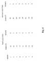
- FIG. 4is a table illustrating one approach for defining mirror groups for the disk configuration illustrated in FIG. 3 .
- 8 different mirror groupsare defined, each having two different regions in which data is mirrored.
- a first mirror groupi.e., group 1
- group 1includes a first location at region X on the upper surface of disk A (i.e., surface A 1 ) and a second location at region Y on the upper surface of disk B (i.e., surface B 1 ).
- any data written to this first locationwill also be written to the corresponding second location.
- a second mirror group(i.e., group 2 ) includes a first storage location at region Y on the upper surface of disk A and a second storage location at region X on the upper surface of disk B.
- group 2includes a first storage location at region Y on the upper surface of disk A and a second storage location at region X on the upper surface of disk B.
- the same patternis used for the remaining disk surfaces.
- each disk surfaceis divided into three 120 degree wedge regions X, Y, and Z. Data is then mirrored in three different places within the stack on three different disk surfaces (e.g., region X on a first disk surface, region Y on a second disk surface, and region Z on a third disk surface).
- a simulated increase in disk rotation speedis achieved during read operations by taking advantage of the unique mirrored data configurations within the disk drive. For example, referring back to FIG. 3, the mirrored data within the different regions of a mirror group will occur in the same cylinder on their respective disk surfaces. Thus, once the read transducers reach the appropriate cylinder, the data will always be available (if the data is uncorrupted and all transducers are functioning) within a 180 rotation of the disk stack 46 . Thus, an effective doubling of the disk rotation speed is achieved. Similarly, for a data configuration using N regions per disk surface, the effective increase in disk speed will be by a factor of N.
- the main controller 28keeps track of the multiple locations associated with each mirror group and can thus determine which location one of the transducers will be able to read first for a new read request. The main controller 28 will then activate the appropriate read transducer at the proper time to read the data. Thus, the average latency experienced during read operations involving smaller files or data blocks is cut in half. Read operations involving larger amounts of data will generally have less of an improvement.
- write throughputis reduced. That is, a write request will normally require a full revolution of the disk stack to complete. The actual reduction will depend upon both the file size and the buffer capability of the disk drive.
- write requests involving larger files, such as those involving greater than N regions of datawill require a cylinder switch instead of a faster head switch.
- the impact of thiscan be reduced through the use of micro-actuator arrangements.
- a write cacheis used to temporarily store data that will later be transferred to the appropriate mirror region. The transfer to the mirror region from the write cache can be postponed until a period of relative inactivity in the disk drive to minimize the impact on write access times.
- the inventive principlesare implemented within a disk drive having multiple independent channels.
- a disk drive that includes two independent write channelsis able to write first data to region X on a disk surface A 1 while simultaneously writing second data (that is different from the first data) to region X on surface B 1 .
- the disk drivecan write the first data to region Y on surface B 1 and the second data to region Y on surface A 1 .
- twice as much datacan be written within a single rotation of the disk stack than a single channel arrangement.
- One of the benefits of the present inventionis that it protects against a loss of data should, for example, one of the read transducers fail.
- functionalityis provided that is capable of detecting the failure of one or more transducers within the drive (e.g., SMART features).
- the disk driveuses this bad transducer information to determine which location to retrieve data from during a read operation. Consequently, the disk drive does not waste time attempting to retrieve data using an inoperative read transducer.
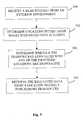
- FIG. 5is a flowchart illustrating a method for performing a read operation in accordance with one embodiment of the present invention.
- a read requestis received by a disk drive from an exterior environment (e.g., from a host computer) requesting that data from an identified disk location be transferred to the exterior environment (step 100 ).
- the disk drivedetermines multiple storage locations within the drive where copies of the requested data are stored (step 102 ).
- the drivedetermines whether any of the transducers associated with the identified locations are inoperative (step 104 ).
- the disk drivemaintains a list of defective transducers that can be quickly referenced by the main controller 28 during a read operation.
- the drivethen proceeds to retrieve the requested data from a location that is associated with an operative read transducer and transfers this data to the requesting entity (step 106 ).
- the disk drivewill select the first identified disk location that will be traversed by an operative read transducer during the corresponding seek operation.
Landscapes
- Engineering & Computer Science (AREA)
- Signal Processing (AREA)
- Signal Processing For Digital Recording And Reproducing (AREA)
Abstract
Description
Claims (7)
Priority Applications (1)
| Application Number | Priority Date | Filing Date | Title |
|---|---|---|---|
| US09/590,311US6493160B1 (en) | 2000-06-08 | 2000-06-08 | Pseudo raid implementation within a single disk drive |
Applications Claiming Priority (1)
| Application Number | Priority Date | Filing Date | Title |
|---|---|---|---|
| US09/590,311US6493160B1 (en) | 2000-06-08 | 2000-06-08 | Pseudo raid implementation within a single disk drive |
Publications (1)
| Publication Number | Publication Date |
|---|---|
| US6493160B1true US6493160B1 (en) | 2002-12-10 |
Family
ID=24361744
Family Applications (1)
| Application Number | Title | Priority Date | Filing Date |
|---|---|---|---|
| US09/590,311Expired - LifetimeUS6493160B1 (en) | 2000-06-08 | 2000-06-08 | Pseudo raid implementation within a single disk drive |
Country Status (1)
| Country | Link |
|---|---|
| US (1) | US6493160B1 (en) |
Cited By (12)
| Publication number | Priority date | Publication date | Assignee | Title |
|---|---|---|---|---|
| US20030051110A1 (en)* | 2001-09-10 | 2003-03-13 | Gaspard Walter A. | Self mirroring disk drive |
| US20040061970A1 (en)* | 2002-09-30 | 2004-04-01 | Dell Products L.P. | System and method for storing information in a disk drive |
| US20050034298A1 (en)* | 2003-08-15 | 2005-02-17 | Hitachi Global Storage Technologies | Disk drive yield optimization by capacity |
| US20070234000A1 (en)* | 2006-03-31 | 2007-10-04 | Dell Products L.P. | Method and system for dynamic management of a utility partition in a pre-operating system environment |
| US20090240905A1 (en)* | 2008-03-18 | 2009-09-24 | Ching-Lung Tsai | Real-time backup method for single storage medium |
| US8521972B1 (en) | 2010-06-30 | 2013-08-27 | Western Digital Technologies, Inc. | System and method for optimizing garbage collection in data storage |
| US20130227217A1 (en)* | 2012-02-29 | 2013-08-29 | Hitachi Consumer Electronics Co., Ltd. | Archive system and processing method |
| US8788778B1 (en) | 2012-06-04 | 2014-07-22 | Western Digital Technologies, Inc. | Garbage collection based on the inactivity level of stored data |
| US8819375B1 (en) | 2011-11-30 | 2014-08-26 | Western Digital Technologies, Inc. | Method for selective defragmentation in a data storage device |
| US9158670B1 (en) | 2011-06-30 | 2015-10-13 | Western Digital Technologies, Inc. | System and method for dynamically adjusting garbage collection policies in solid-state memory |
| US9189392B1 (en) | 2011-06-30 | 2015-11-17 | Western Digital Technologies, Inc. | Opportunistic defragmentation during garbage collection |
| US20170168908A1 (en)* | 2015-12-14 | 2017-06-15 | International Business Machines Corporation | Storing data in multi-region storage devices |
Citations (3)
| Publication number | Priority date | Publication date | Assignee | Title |
|---|---|---|---|---|
| US3729725A (en)* | 1971-09-13 | 1973-04-24 | Digital Dev Corp | Redundant recordation to reduce access time |
| US5390313A (en)* | 1990-09-24 | 1995-02-14 | Emc Corporation | Data storage system with data mirroring and reduced access time data retrieval |
| US6118602A (en)* | 1997-10-31 | 2000-09-12 | Stmicroelectronics, Inc. | Preamplifier for a read/write head |
- 2000
- 2000-06-08USUS09/590,311patent/US6493160B1/ennot_activeExpired - Lifetime
Patent Citations (3)
| Publication number | Priority date | Publication date | Assignee | Title |
|---|---|---|---|---|
| US3729725A (en)* | 1971-09-13 | 1973-04-24 | Digital Dev Corp | Redundant recordation to reduce access time |
| US5390313A (en)* | 1990-09-24 | 1995-02-14 | Emc Corporation | Data storage system with data mirroring and reduced access time data retrieval |
| US6118602A (en)* | 1997-10-31 | 2000-09-12 | Stmicroelectronics, Inc. | Preamplifier for a read/write head |
Cited By (17)
| Publication number | Priority date | Publication date | Assignee | Title |
|---|---|---|---|---|
| US20030051110A1 (en)* | 2001-09-10 | 2003-03-13 | Gaspard Walter A. | Self mirroring disk drive |
| US20040061970A1 (en)* | 2002-09-30 | 2004-04-01 | Dell Products L.P. | System and method for storing information in a disk drive |
| US6917490B2 (en)* | 2002-09-30 | 2005-07-12 | Dell Products L.P. | System and method for storing information in a disk drive |
| US20050034298A1 (en)* | 2003-08-15 | 2005-02-17 | Hitachi Global Storage Technologies | Disk drive yield optimization by capacity |
| US20070234000A1 (en)* | 2006-03-31 | 2007-10-04 | Dell Products L.P. | Method and system for dynamic management of a utility partition in a pre-operating system environment |
| US20090240905A1 (en)* | 2008-03-18 | 2009-09-24 | Ching-Lung Tsai | Real-time backup method for single storage medium |
| US8706985B1 (en) | 2010-06-30 | 2014-04-22 | Western Digital Technologies, Inc. | System and method for optimizing garbage collection in data storage |
| US8521972B1 (en) | 2010-06-30 | 2013-08-27 | Western Digital Technologies, Inc. | System and method for optimizing garbage collection in data storage |
| US9158670B1 (en) | 2011-06-30 | 2015-10-13 | Western Digital Technologies, Inc. | System and method for dynamically adjusting garbage collection policies in solid-state memory |
| US9189392B1 (en) | 2011-06-30 | 2015-11-17 | Western Digital Technologies, Inc. | Opportunistic defragmentation during garbage collection |
| US9678671B2 (en) | 2011-06-30 | 2017-06-13 | Western Digital Technologies, Inc. | System and method for dynamically adjusting garbage collection policies in solid-state memory |
| US8819375B1 (en) | 2011-11-30 | 2014-08-26 | Western Digital Technologies, Inc. | Method for selective defragmentation in a data storage device |
| US20130227217A1 (en)* | 2012-02-29 | 2013-08-29 | Hitachi Consumer Electronics Co., Ltd. | Archive system and processing method |
| US8788778B1 (en) | 2012-06-04 | 2014-07-22 | Western Digital Technologies, Inc. | Garbage collection based on the inactivity level of stored data |
| US20170168908A1 (en)* | 2015-12-14 | 2017-06-15 | International Business Machines Corporation | Storing data in multi-region storage devices |
| US9880913B2 (en)* | 2015-12-14 | 2018-01-30 | International Business Machines Corporation | Storing data in multi-region storage devices |
| US10572356B2 (en) | 2015-12-14 | 2020-02-25 | International Business Machines Corporation | Storing data in multi-region storage devices |
Similar Documents
| Publication | Publication Date | Title |
|---|---|---|
| US6973553B1 (en) | Method and apparatus for using extended disk sector formatting to assist in backup and hierarchical storage management | |
| US6115788A (en) | Multi-drive array with improved data transfer rate performance | |
| US5463758A (en) | System and method for reducing seek time for read operations in mirrored DASD files | |
| US6950900B1 (en) | Method and apparatus for migrating data having a format of a first type to a format of a second type | |
| CN110827861A (en) | Multi-actuator drive providing replication using multiple volumes | |
| US6493160B1 (en) | Pseudo raid implementation within a single disk drive | |
| US5784216A (en) | Method and apparatus for recording defective track identification information in a disk drive | |
| US7206990B2 (en) | Data sector error handling mechanism | |
| JPH0423273A (en) | Optical disk recording and reproducing device | |
| US20020138694A1 (en) | Magnetic disc drive, method for recording data, and method for reproducing data | |
| US5353170A (en) | Error recovery data storage system and method with two position read verification | |
| JP3645049B2 (en) | Servo address device and positioning method for read, write and seek operations in a direct access storage device | |
| JPH052830A (en) | Recording / reproducing apparatus and recording / reproducing method in recording / reproducing apparatus | |
| US6079044A (en) | Method and error correcting code (ECC) apparatus for storing predefined information with ECC in a direct access storage device | |
| US6993688B2 (en) | Data sector error tracking and correction mechanism | |
| JPH04265504A (en) | Apparatus and method for determining position of heat which is erroneously positioned | |
| US7433149B1 (en) | Media surface with servo data in customer data region | |
| US6941488B2 (en) | Retrieval of a single complete copy from multiple stored copies of information | |
| JP3590390B2 (en) | Self-mirroring method in disk storage device and disk storage device to which the method is applied | |
| US6728053B2 (en) | Method and apparatus to reduce retry redundancy during read operations | |
| US20010052051A1 (en) | Method of controlling data access and system thereof | |
| JP3341094B2 (en) | Recording medium reading device | |
| US6646823B1 (en) | Disk drive using offset data sectors | |
| JP2000099279A (en) | Data duplication method | |
| JPH0962461A (en) | Automatic data restoring method for disk array device |
Legal Events
| Date | Code | Title | Description |
|---|---|---|---|
| AS | Assignment | Owner name:MAXTOR CORPORATION, COLORADO Free format text:ASSIGNMENT OF ASSIGNORS INTEREST;ASSIGNOR:SCHRECK, ERHARD;REEL/FRAME:010865/0430 Effective date:20000523 | |
| AS | Assignment | Owner name:MAXTOR CORPORATION, COLORADO Free format text:ASSIGNMENT OF ASSIGNORS INTEREST;ASSIGNORS:SCHRECK, ERHARD;YEUNG, GARRICK;REEL/FRAME:011386/0207 Effective date:20001013 | |
| STCF | Information on status: patent grant | Free format text:PATENTED CASE | |
| FPAY | Fee payment | Year of fee payment:4 | |
| AS | Assignment | Owner name:WELLS FARGO BANK, NATIONAL ASSOCIATION, AS COLLATERAL AGENT AND SECOND PRIORITY REPRESENTATIVE, CALIFORNIA Free format text:SECURITY AGREEMENT;ASSIGNORS:MAXTOR CORPORATION;SEAGATE TECHNOLOGY LLC;SEAGATE TECHNOLOGY INTERNATIONAL;REEL/FRAME:022757/0017 Effective date:20090507 Owner name:JPMORGAN CHASE BANK, N.A., AS ADMINISTRATIVE AGENT AND FIRST PRIORITY REPRESENTATIVE, NEW YORK Free format text:SECURITY AGREEMENT;ASSIGNORS:MAXTOR CORPORATION;SEAGATE TECHNOLOGY LLC;SEAGATE TECHNOLOGY INTERNATIONAL;REEL/FRAME:022757/0017 Effective date:20090507 Owner name:JPMORGAN CHASE BANK, N.A., AS ADMINISTRATIVE AGENT Free format text:SECURITY AGREEMENT;ASSIGNORS:MAXTOR CORPORATION;SEAGATE TECHNOLOGY LLC;SEAGATE TECHNOLOGY INTERNATIONAL;REEL/FRAME:022757/0017 Effective date:20090507 Owner name:WELLS FARGO BANK, NATIONAL ASSOCIATION, AS COLLATE Free format text:SECURITY AGREEMENT;ASSIGNORS:MAXTOR CORPORATION;SEAGATE TECHNOLOGY LLC;SEAGATE TECHNOLOGY INTERNATIONAL;REEL/FRAME:022757/0017 Effective date:20090507 | |
| FPAY | Fee payment | Year of fee payment:8 | |
| AS | Assignment | Owner name:SEAGATE TECHNOLOGY HDD HOLDINGS, CALIFORNIA Free format text:RELEASE;ASSIGNOR:JPMORGAN CHASE BANK, N.A., AS ADMINISTRATIVE AGENT;REEL/FRAME:025662/0001 Effective date:20110114 Owner name:SEAGATE TECHNOLOGY LLC, CALIFORNIA Free format text:RELEASE;ASSIGNOR:JPMORGAN CHASE BANK, N.A., AS ADMINISTRATIVE AGENT;REEL/FRAME:025662/0001 Effective date:20110114 Owner name:MAXTOR CORPORATION, CALIFORNIA Free format text:RELEASE;ASSIGNOR:JPMORGAN CHASE BANK, N.A., AS ADMINISTRATIVE AGENT;REEL/FRAME:025662/0001 Effective date:20110114 Owner name:SEAGATE TECHNOLOGY INTERNATIONAL, CALIFORNIA Free format text:RELEASE;ASSIGNOR:JPMORGAN CHASE BANK, N.A., AS ADMINISTRATIVE AGENT;REEL/FRAME:025662/0001 Effective date:20110114 | |
| AS | Assignment | Owner name:THE BANK OF NOVA SCOTIA, AS ADMINISTRATIVE AGENT, CANADA Free format text:SECURITY AGREEMENT;ASSIGNOR:SEAGATE TECHNOLOGY LLC;REEL/FRAME:026010/0350 Effective date:20110118 Owner name:THE BANK OF NOVA SCOTIA, AS ADMINISTRATIVE AGENT, Free format text:SECURITY AGREEMENT;ASSIGNOR:SEAGATE TECHNOLOGY LLC;REEL/FRAME:026010/0350 Effective date:20110118 | |
| AS | Assignment | Owner name:SEAGATE TECHNOLOGY LLC, CALIFORNIA Free format text:TERMINATION AND RELEASE OF SECURITY INTEREST IN PATENT RIGHTS;ASSIGNOR:WELLS FARGO BANK, NATIONAL ASSOCIATION, AS COLLATERAL AGENT AND SECOND PRIORITY REPRESENTATIVE;REEL/FRAME:030833/0001 Effective date:20130312 Owner name:EVAULT INC. (F/K/A I365 INC.), CALIFORNIA Free format text:TERMINATION AND RELEASE OF SECURITY INTEREST IN PATENT RIGHTS;ASSIGNOR:WELLS FARGO BANK, NATIONAL ASSOCIATION, AS COLLATERAL AGENT AND SECOND PRIORITY REPRESENTATIVE;REEL/FRAME:030833/0001 Effective date:20130312 Owner name:SEAGATE TECHNOLOGY INTERNATIONAL, CAYMAN ISLANDS Free format text:TERMINATION AND RELEASE OF SECURITY INTEREST IN PATENT RIGHTS;ASSIGNOR:WELLS FARGO BANK, NATIONAL ASSOCIATION, AS COLLATERAL AGENT AND SECOND PRIORITY REPRESENTATIVE;REEL/FRAME:030833/0001 Effective date:20130312 Owner name:SEAGATE TECHNOLOGY US HOLDINGS, INC., CALIFORNIA Free format text:TERMINATION AND RELEASE OF SECURITY INTEREST IN PATENT RIGHTS;ASSIGNOR:WELLS FARGO BANK, NATIONAL ASSOCIATION, AS COLLATERAL AGENT AND SECOND PRIORITY REPRESENTATIVE;REEL/FRAME:030833/0001 Effective date:20130312 | |
| FPAY | Fee payment | Year of fee payment:12 | |
| AS | Assignment | Owner name:SEAGATE TECHNOLOGY PUBLIC LIMITED COMPANY, CALIFORNIA Free format text:RELEASE BY SECURED PARTY;ASSIGNOR:THE BANK OF NOVA SCOTIA;REEL/FRAME:072193/0001 Effective date:20250303 Owner name:SEAGATE TECHNOLOGY, CALIFORNIA Free format text:RELEASE BY SECURED PARTY;ASSIGNOR:THE BANK OF NOVA SCOTIA;REEL/FRAME:072193/0001 Effective date:20250303 Owner name:SEAGATE TECHNOLOGY HDD HOLDINGS, CALIFORNIA Free format text:RELEASE BY SECURED PARTY;ASSIGNOR:THE BANK OF NOVA SCOTIA;REEL/FRAME:072193/0001 Effective date:20250303 Owner name:I365 INC., CALIFORNIA Free format text:RELEASE BY SECURED PARTY;ASSIGNOR:THE BANK OF NOVA SCOTIA;REEL/FRAME:072193/0001 Effective date:20250303 Owner name:SEAGATE TECHNOLOGY LLC, CALIFORNIA Free format text:RELEASE BY SECURED PARTY;ASSIGNOR:THE BANK OF NOVA SCOTIA;REEL/FRAME:072193/0001 Effective date:20250303 Owner name:SEAGATE TECHNOLOGY INTERNATIONAL, CAYMAN ISLANDS Free format text:RELEASE BY SECURED PARTY;ASSIGNOR:THE BANK OF NOVA SCOTIA;REEL/FRAME:072193/0001 Effective date:20250303 Owner name:SEAGATE HDD CAYMAN, CAYMAN ISLANDS Free format text:RELEASE BY SECURED PARTY;ASSIGNOR:THE BANK OF NOVA SCOTIA;REEL/FRAME:072193/0001 Effective date:20250303 Owner name:SEAGATE TECHNOLOGY (US) HOLDINGS, INC., CALIFORNIA Free format text:RELEASE BY SECURED PARTY;ASSIGNOR:THE BANK OF NOVA SCOTIA;REEL/FRAME:072193/0001 Effective date:20250303 |