US6492955B1 - Steerable antenna system with fixed feed source - Google Patents
Steerable antenna system with fixed feed sourceDownload PDFInfo
- Publication number
- US6492955B1 US6492955B1US09/967,949US96794901AUS6492955B1US 6492955 B1US6492955 B1US 6492955B1US 96794901 AUS96794901 AUS 96794901AUS 6492955 B1US6492955 B1US 6492955B1
- Authority
- US
- United States
- Prior art keywords
- target
- axis
- source
- signal
- rotating
- Prior art date
- Legal status (The legal status is an assumption and is not a legal conclusion. Google has not performed a legal analysis and makes no representation as to the accuracy of the status listed.)
- Expired - Lifetime
Links
Images


Classifications
- H—ELECTRICITY
- H01—ELECTRIC ELEMENTS
- H01Q—ANTENNAS, i.e. RADIO AERIALS
- H01Q19/00—Combinations of primary active antenna elements and units with secondary devices, e.g. with quasi-optical devices, for giving the antenna a desired directional characteristic
- H01Q19/10—Combinations of primary active antenna elements and units with secondary devices, e.g. with quasi-optical devices, for giving the antenna a desired directional characteristic using reflecting surfaces
- H01Q19/18—Combinations of primary active antenna elements and units with secondary devices, e.g. with quasi-optical devices, for giving the antenna a desired directional characteristic using reflecting surfaces having two or more spaced reflecting surfaces
- H01Q19/19—Combinations of primary active antenna elements and units with secondary devices, e.g. with quasi-optical devices, for giving the antenna a desired directional characteristic using reflecting surfaces having two or more spaced reflecting surfaces comprising one main concave reflecting surface associated with an auxiliary reflecting surface
- H01Q19/192—Combinations of primary active antenna elements and units with secondary devices, e.g. with quasi-optical devices, for giving the antenna a desired directional characteristic using reflecting surfaces having two or more spaced reflecting surfaces comprising one main concave reflecting surface associated with an auxiliary reflecting surface with dual offset reflectors
- H—ELECTRICITY
- H01—ELECTRIC ELEMENTS
- H01Q—ANTENNAS, i.e. RADIO AERIALS
- H01Q3/00—Arrangements for changing or varying the orientation or the shape of the directional pattern of the waves radiated from an antenna or antenna system
- H01Q3/12—Arrangements for changing or varying the orientation or the shape of the directional pattern of the waves radiated from an antenna or antenna system using mechanical relative movement between primary active elements and secondary devices of antennas or antenna systems
- H01Q3/16—Arrangements for changing or varying the orientation or the shape of the directional pattern of the waves radiated from an antenna or antenna system using mechanical relative movement between primary active elements and secondary devices of antennas or antenna systems for varying relative position of primary active element and a reflecting device
- H01Q3/20—Arrangements for changing or varying the orientation or the shape of the directional pattern of the waves radiated from an antenna or antenna system using mechanical relative movement between primary active elements and secondary devices of antennas or antenna systems for varying relative position of primary active element and a reflecting device wherein the primary active element is fixed and the reflecting device is movable
Definitions
- the present inventionrelates to the field of antennas and is more particularly concerned with steerable antenna systems for transmitting and/or receiving electromagnetic signals.
- steerable antenna systemsit is well known in the art to use steerable (or tracking) antenna systems to communicate with a relatively moving target. Especially in the aerospace industry, such steerable antennas preferably need to have a high gain, low mass, and a high reliability.
- One way to achieve such an antenna systemis to provide a fixed feed source, thereby eliminating performance degradations otherwise associated with a moving feed source. These degradations include losses due to mechanical rotary joints, RF cable connectors; flexible waveguides, long-length RF cables associated with cable wrap units mounted on rotary actuators or the like.
- steerable/tracking antennasshould be designed such as to avoid a so-called keyhole effect, which is a physical limitation due to the orientation of the antenna rotation axis and caused by a limited motion range of an actuator or the like. This effect forces the antenna to momentarily disrupt communication when reaching the physical limitation to allow for the actuators to reposition before resuming the steering, thereby seriously affecting the communication capabilities of the entire antenna system.
- U.S. Pat. No. 6,043,788 granted on Mar. 28, 2000 to Seaveydiscloses tracking antenna system that is substantially robust and includes a large quantity of moving components that reduce the overall reliability of the system. Also, the steering angle range of the system is limited by the fixed angle between the boresite of the offset paraboloidal reflector and the kappa axis determined by the distance between the offset ellipsoidal subreflector and the offset paraboloidal reflector; a wide range requiring a large distance there between, resulting in a large antenna system that would not be practical especially for spaceborne applications.
- Another object of the present inventionis to provide a steerable antenna system with a fixed feed source that enables beam steering over a full spherical (4 ⁇ steradians) angular range with minimum blockage from its own structure, whenever allowed by the supporting platform.
- a further object of the present inventionis to provide a steerable antenna system with a fixed feed source that enables tracking of a remote station without any keyhole effect over any hemispherical coverage (2 ⁇ steradians).
- Yet another object of the present inventionis to provide a steerable antenna system with a fixed feed source having a high gain, an excellent polarization purity and/or low sidelobes.
- Still another object of the present inventionis to provide a steerable antenna system with fixed feed source having simple actuation devices as well as locations of the same.
- Another object of the present inventionis to provide a fixed-feed source steerable antenna system that can be so positioned with a first actuator as to enable tracking of a same orbiting remote station using only a second actuator when the orbit passes in proximity to the zenith of the system location.
- a further object of the present inventionis to provide a fixed-feed source steerable antenna system that can be mounted on either an orbiting spacecraft or a fixed station and track a ground station or an orbiting spacecraft respectively, or be mounted on a spacecraft and track another spacecraft.
- a steerable antenna systemfor transmitting and/or receiving an electromagnetic signal to/from a target relatively moving therearound, said system comprises:
- a hyperbolic subreflectorsecured to a frame rotatably mounted on a support structure
- a feed sourcelocated at a first focus of the subreflector for transmitting and receiving the signal to and from the same respectively, the feed source being secured to the support structure and having a source axis pointing at the subreflector;
- parabolic reflectorhaving a focus in common with a second focus of the subreflector for transferring the signal from and to the same respectively; the parabolic reflector being secured to the frame and having a beam axis;
- planar reflectorhaving a normal axis intersecting the beam axis with a predetermined angle for transferring the signal from and to the parabolic reflector respectively, the planar reflector being rotatably mounted on the frame for transferring the signal to and from the target;
- a second rotating memberrotating the planar reflector about the beam axis, thereby having the system to steer at the target.
- the systemincludes a controller controlling rotation of the first and the second rotating members; thereby controlling the system to steer at the target.
- the first and the second rotating membersallow for the antenna system to steer at the target anywhere within a full spherical angular range.
- the source axis and the beam axisare co-planar, thereby defining an antenna plane rotating about the source axis.
- the beam axisis perpendicular to the source axis.
- the planar reflectoris of a generally elliptical shape to provide circular projections along the beam axis and a direction of the target.
- the predetermined angleis a 45-degree angle, thereby reflecting the signal from the parabolic reflector within a signal plane perpendicular to the beam axis.
- the feed source including a horn and the support structureare mounted on a generally planar platform substantially parallel to the source axis.
- the feed source including a horn and the support structureare mounted on a generally planar platform substantially perpendicular to the source axis.
- the controllerincludes a first and a second encoders mounted on the first and the second rotating members respectively for providing feedback of a position of the respective rotating member to the controller.
- the feed sourceis a dual frequency dual circular polarization feed source.
- the controllersimultaneously drives the first and the second rotating members to have the antenna system steering in a desired direction.
- the controllerprovides commands to the first and the second rotating members that automatically steer at the moving target.
- the first and the second rotating membersare a first and a second stepper motors respectively.
- the frameminimizes blockage and interference of the signal.
- the support structureis mounted on a spacecraft planet facing panel and the target is a ground station, the spacecraft orbiting around a planet.
- the support structure and the targetare mounted on a first and a second spacecraft respectively, the first and the second spacecraft orbiting around a same planet.
- the support structureis mounted on a ground station and the target is an orbiting spacecraft.
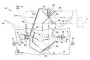
- FIG. 1is a plan view of an embodiment of a steerable antenna system with a fixed feed source according to the present invention mounted on a support structure with the feed source axis parallel to the same, elevation and cross-elevation angles of zero and 180° respectively;
- FIG. 2is a side view taken along line 2 — 2 of FIG. 1;
- FIG. 3is a side view taken along line 3 — 3 of FIG. 1;
- FIG. 4is a schematic perspective illustration showing the steering motion of the embodiment of FIG. 1 under activation of both actuator members for steering at relatively moving target such as an orbiting spacecraft or the like;
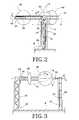
- FIG. 5is a partially sectioned side view of a second embodiment of a steerable antenna system with a fixed feed source according to the present invention, showing the system mounted on a support structure with the feed source axis perpendicular to the same.
- FIGS. 1 to 3there is shown an embodiment 10 of a steerable antenna system with a fixed feed source according to the present invention mounted on a support structure 12 for transmitting and/or receiving an electromagnetic signal 14 to and/or from a target T relatively moving or orbiting around the same.
- the antenna system 10includes a fixed RF (Radio Frequency) or the like feed source 30 , preferably including a horn 32 connected to a conventional waveguide 34 or the like, secured to the support structure 12 and having a source axis A pointing at a hyperbolic subreflector 20 secured to a frame member 22 that is rotatably mounted on the structure 12 , preferably secured to a planar platform P.
- the generally C-shaped frame 22also supports a parabolic reflector 40 and a flat reflector 50 , rigidly and rotatably mounted thereon, respectively.
- the subreflector 20is so oriented as to have its first F 1 and second F 2 focal points (or focus) in common with the focal point of the feed source 30 and the parabolic reflector 40 , respectively.
- the latteris so oriented as to reflect (or transfer) the signal 14 received from the subreflector 20 to the flat reflector 50 along a beam axis B and vice-versa.
- the feed source 30 , subreflector 20 , parabolic reflector 40 and flat reflector 50all lie within a same antenna plane or elevation plane E. Accordingly, the source A and beam B axes are co-planar, and preferably perpendicular to each other, for the antenna system 10 to be as compact as possible.
- a first rotating member 24preferably a first rotating actuator such as a stepper motor or the like, mounted on the structure 12 rotates the frame 22 along with the subreflector 20 , the parabolic 40 and flat 50 reflectors about the source axis A.
- a second rotating member 52preferably a second rotating stepper motor actuator, mounted on the frame 22 rotates the flat reflector 50 preferably about the beam axis B; as illustrated in FIG. 1 with the flat reflector 50 shown in solid and dashed lines to reflect the signal 14 to the right and left hand side, respectively.
- the flat reflector 50is preferably elliptic in shape in order to provide a circular projected aperture along the beam axis B and the direction of the target T, in these two positions.
- a controller member 60is preferably connected to the motors 24 , 52 via a first 62 and a second 64 encoders (or the like) respectively to control the rotation of the same; thereby controlling the system antenna 10 to steer at the target T, preferably anywhere within a full spherical angular range.
- the normal axis C of the flat reflector 50preferably makes a forty-five degree (45°) constant angle a relative to the beam axis B to reflect the signal 14 coming from the parabolic reflector 40 within a signal plane or cross-elevation (x-elevation) plane X perpendicular to the elevation plane E and parallel to the source axis A. Consequently, the projection of the flat reflector 50 perpendicular to both the output signal 14 direction and the beam axis B is circular as shown in FIGS. 2 and 3, respectively.
- the first 24 and second 52 motorsare the elevation and x-elevation motors adjusting the reference elevation angle ⁇ and x-elevation angle ⁇ of the antenna system 10 respectively.
- the source A and beam B axesare the elevation and x-elevation axes respectively.
- both the elevation motor 24 and the horn 32are mounted on respective brackets 16 , 18 of the structure 12 to allow for the frame 22 to clear the same during its rotational displacement about the source axis A, as seen in FIGS. 2 and 3.
- the actual shapes of the horn 32 , subreflector 20 , parabolic reflector 40 and flat reflector 50are determined to maximize the overall electrical antenna gain as it would be obvious to anyone having ordinary skill in the art, also considering its performance in all other aspects such as mechanical, power, reliability, cost, manufacturability, etc.
- the feed source 30is a dual frequency dual circular polarization feed source or any other suitable electromagnetic signal source.
- the platform Prepresents a spacecraft Earth facing panel and the target T is a ground station on the Earth surface; the spacecraft orbiting around the Earth (or any other planet or the like).
- the antenna system 10could be a ground station steering at an orbiting spacecraft to transmit and/or receive signal to/from the same.
- the antenna system 10 of the present invention mounted on an orbiting spacecraftcan also be used to communicate with a similar antenna system 10 mounted on another orbiting spacecraft, whereby the two antenna systems 10 would continuously steer at each other while the two spacecraft are moving in their respective orbits.
- controller member 60can simultaneously drive the two motors 24 , 52 to have the antenna system 10 sequentially and continuously steering at a moving target in any desired direction.
- FIG. 4there is shown a schematic perspective sequential illustration of the steering coverage of the antenna system 10 (shown in dashed lines) of the present invention with the rotational displacement ⁇ of the output signal 14 (shown by all the coplanar arrows in dashed lines) about the x-elevation axis B to form the x-elevation plane X, and the rotational displacement ⁇ of both elevation E and x-elevation X planes about the elevation axis A to substantially cover the full spherical angle around the antenna system 10 .
- the motionbeing represented in FIG.
- the controller 60When the antenna system 10 has to track a moving target T for a short period of time over a relatively small angular range, it is possible for the controller 60 to properly position the antenna system 10 using the elevation motor 24 such that only the x-elevation motor 52 is used for the tracking itself of the target T, considering that the path of the target T essentially remains within a same plane, the x-elevation plane X, as seen by the antenna system 10 .
- FIG. 5there is shown a second embodiment 10 a of the antenna system positioned with the elevation source axis A essentially perpendicular to the platform P.
- the bracket 18 ais substantially reduced down to a simple mounting bracket connected to the horn 32 that points upward at the subreflector 20 , thus limiting the run of the waveguide 34 connecting thereto, and the signal losses associated therewith.
- the bracket 16 ais also reduced down to a simple support for the elevation, motor 24 a itself supporting the rotating frame 22 a .
- the elevation motor 24 ais preferably hollowed to enable the fixed horn 32 to be centered and point at the subreflector 20 without being affected by the rotation induced by the same 24 a to the frame 22 a.
Landscapes
- Variable-Direction Aerials And Aerial Arrays (AREA)
Abstract
Description
Claims (19)
Priority Applications (1)
| Application Number | Priority Date | Filing Date | Title |
|---|---|---|---|
| US09/967,949US6492955B1 (en) | 2001-10-02 | 2001-10-02 | Steerable antenna system with fixed feed source |
Applications Claiming Priority (1)
| Application Number | Priority Date | Filing Date | Title |
|---|---|---|---|
| US09/967,949US6492955B1 (en) | 2001-10-02 | 2001-10-02 | Steerable antenna system with fixed feed source |
Publications (1)
| Publication Number | Publication Date |
|---|---|
| US6492955B1true US6492955B1 (en) | 2002-12-10 |
Family
ID=25513517
Family Applications (1)
| Application Number | Title | Priority Date | Filing Date |
|---|---|---|---|
| US09/967,949Expired - LifetimeUS6492955B1 (en) | 2001-10-02 | 2001-10-02 | Steerable antenna system with fixed feed source |
Country Status (1)
| Country | Link |
|---|---|
| US (1) | US6492955B1 (en) |
Cited By (19)
| Publication number | Priority date | Publication date | Assignee | Title |
|---|---|---|---|---|
| US6580399B1 (en)* | 2002-01-11 | 2003-06-17 | Northrop Grumman Corporation | Antenna system having positioning mechanism for reflector |
| US6690332B1 (en)* | 1999-04-22 | 2004-02-10 | Saabtech Electronics Ab | Antenna method and device with predictive scan position |
| US20040066344A1 (en)* | 2002-10-08 | 2004-04-08 | Eric Amyotte | Steerable offset antenna with fixed feed source |
| EP1414110A1 (en)* | 2002-10-23 | 2004-04-28 | EMS Technologies Canada, Limited | Steerable antenna system with fixed feed source |
| US7411561B1 (en)* | 2005-04-27 | 2008-08-12 | The Boeing Company | Gimbaled dragonian antenna |
| WO2008101619A1 (en)* | 2007-02-21 | 2008-08-28 | Smiths Heimann Gmbh | Apparatus for depicting test objects using electromagnetic waves, particularly for checking people for suspicious articles |
| US20080204341A1 (en)* | 2007-02-26 | 2008-08-28 | Baldauf John E | Beam waveguide including mizuguchi condition reflector sets |
| US7656345B2 (en) | 2006-06-13 | 2010-02-02 | Ball Aerospace & Technoloiges Corp. | Low-profile lens method and apparatus for mechanical steering of aperture antennas |
| US20110043403A1 (en)* | 2008-02-27 | 2011-02-24 | Synview Gmbh | Millimeter wave camera with improved resolution through the use of the sar principle in combination with a focusing optic |
| US20130106649A1 (en)* | 2011-10-31 | 2013-05-02 | Kenneth W. Brown | Methods and apparatus for wide area synthetic aperture radar detection |
| US20150180120A1 (en)* | 2013-12-19 | 2015-06-25 | Interdigital Patent Holdings, Inc. | Antenna reflector system |
| US9093742B2 (en) | 2011-10-17 | 2015-07-28 | McDonald, Dettwiler and Associates Corporation | Wide scan steerable antenna with no key-hole |
| CN105206936A (en)* | 2015-08-25 | 2015-12-30 | 西安电子科技大学 | Double-frequency nested circular polarization navigation antenna |
| US20160072185A1 (en)* | 2014-09-10 | 2016-03-10 | Macdonald, Dettwiler And Associates Corporation | Wide scan steerable antenna |
| US20170040684A1 (en)* | 2015-08-05 | 2017-02-09 | Harris Corporation | Steerable satellite antenna assembly with fixed antenna feed and associated methods |
| US9929474B2 (en)* | 2015-07-02 | 2018-03-27 | Sea Tel, Inc. | Multiple-feed antenna system having multi-position subreflector assembly |
| US10483637B2 (en) | 2015-08-10 | 2019-11-19 | Viasat, Inc. | Method and apparatus for beam-steerable antenna with single-drive mechanism |
| US10484110B2 (en)* | 2017-04-03 | 2019-11-19 | Ets-Lindgren, Inc. | Method and system for testing beam forming capabilities of wireless devices |
| US20240235021A1 (en)* | 2024-03-20 | 2024-07-11 | Custom Microwave Inc. | Segmented ultra-wideband antenna system and method of operating the same |
Citations (12)
| Publication number | Priority date | Publication date | Assignee | Title |
|---|---|---|---|---|
| US3848255A (en) | 1973-03-22 | 1974-11-12 | Teledyne Inc | Steerable radar antenna |
| US4425566A (en) | 1981-08-31 | 1984-01-10 | Bell Telephone Laboratories, Incorporated | Antenna arrangement for providing a frequency independent field distribution with a small feedhorn |
| US4668955A (en) | 1983-11-14 | 1987-05-26 | Ford Aerospace & Communications Corporation | Plural reflector antenna with relatively moveable reflectors |
| US4772892A (en) | 1984-11-13 | 1988-09-20 | Raytheon Company | Two-axis gimbal |
| US5198827A (en) | 1991-05-23 | 1993-03-30 | Hughes Aircraft Company | Dual reflector scanning antenna system |
| US5229781A (en) | 1990-03-28 | 1993-07-20 | Selenia Spazio S.P.A. | Fine pointing system for reflector type antennas |
| US5485168A (en)* | 1994-12-21 | 1996-01-16 | Electrospace Systems, Inc. | Multiband satellite communication antenna system with retractable subreflector |
| US5579021A (en) | 1995-03-17 | 1996-11-26 | Hughes Aircraft Company | Scanned antenna system |
| US5684494A (en) | 1994-12-15 | 1997-11-04 | Daimler-Benz Aerospace Ag | Reflector antenna, especially for a communications satellite |
| US5844527A (en)* | 1993-02-12 | 1998-12-01 | Furuno Electric Company, Limited | Radar antenna |
| US6043788A (en) | 1998-07-31 | 2000-03-28 | Seavey; John M. | Low earth orbit earth station antenna |
| US6191744B1 (en)* | 1999-09-27 | 2001-02-20 | Jeffrey Snow | Probe movement system for spherical near-field antenna testing |
- 2001
- 2001-10-02USUS09/967,949patent/US6492955B1/ennot_activeExpired - Lifetime
Patent Citations (12)
| Publication number | Priority date | Publication date | Assignee | Title |
|---|---|---|---|---|
| US3848255A (en) | 1973-03-22 | 1974-11-12 | Teledyne Inc | Steerable radar antenna |
| US4425566A (en) | 1981-08-31 | 1984-01-10 | Bell Telephone Laboratories, Incorporated | Antenna arrangement for providing a frequency independent field distribution with a small feedhorn |
| US4668955A (en) | 1983-11-14 | 1987-05-26 | Ford Aerospace & Communications Corporation | Plural reflector antenna with relatively moveable reflectors |
| US4772892A (en) | 1984-11-13 | 1988-09-20 | Raytheon Company | Two-axis gimbal |
| US5229781A (en) | 1990-03-28 | 1993-07-20 | Selenia Spazio S.P.A. | Fine pointing system for reflector type antennas |
| US5198827A (en) | 1991-05-23 | 1993-03-30 | Hughes Aircraft Company | Dual reflector scanning antenna system |
| US5844527A (en)* | 1993-02-12 | 1998-12-01 | Furuno Electric Company, Limited | Radar antenna |
| US5684494A (en) | 1994-12-15 | 1997-11-04 | Daimler-Benz Aerospace Ag | Reflector antenna, especially for a communications satellite |
| US5485168A (en)* | 1994-12-21 | 1996-01-16 | Electrospace Systems, Inc. | Multiband satellite communication antenna system with retractable subreflector |
| US5579021A (en) | 1995-03-17 | 1996-11-26 | Hughes Aircraft Company | Scanned antenna system |
| US6043788A (en) | 1998-07-31 | 2000-03-28 | Seavey; John M. | Low earth orbit earth station antenna |
| US6191744B1 (en)* | 1999-09-27 | 2001-02-20 | Jeffrey Snow | Probe movement system for spherical near-field antenna testing |
Cited By (39)
| Publication number | Priority date | Publication date | Assignee | Title |
|---|---|---|---|---|
| US6690332B1 (en)* | 1999-04-22 | 2004-02-10 | Saabtech Electronics Ab | Antenna method and device with predictive scan position |
| US6580399B1 (en)* | 2002-01-11 | 2003-06-17 | Northrop Grumman Corporation | Antenna system having positioning mechanism for reflector |
| US20040066344A1 (en)* | 2002-10-08 | 2004-04-08 | Eric Amyotte | Steerable offset antenna with fixed feed source |
| US6747604B2 (en)* | 2002-10-08 | 2004-06-08 | Ems Technologies Canada, Inc. | Steerable offset antenna with fixed feed source |
| EP1414110A1 (en)* | 2002-10-23 | 2004-04-28 | EMS Technologies Canada, Limited | Steerable antenna system with fixed feed source |
| US7411561B1 (en)* | 2005-04-27 | 2008-08-12 | The Boeing Company | Gimbaled dragonian antenna |
| US8068053B1 (en) | 2006-06-13 | 2011-11-29 | Ball Aerospace & Technologies Corp. | Low-profile lens method and apparatus for mechanical steering of aperture antennas |
| US7656345B2 (en) | 2006-06-13 | 2010-02-02 | Ball Aerospace & Technoloiges Corp. | Low-profile lens method and apparatus for mechanical steering of aperture antennas |
| WO2008101619A1 (en)* | 2007-02-21 | 2008-08-28 | Smiths Heimann Gmbh | Apparatus for depicting test objects using electromagnetic waves, particularly for checking people for suspicious articles |
| US20100045514A1 (en)* | 2007-02-21 | 2010-02-25 | Bernd Bartscher | Device for imaging test objects using electromagnetic waves, in particular for inspecting people for suspicious items |
| US8169355B2 (en) | 2007-02-21 | 2012-05-01 | Smiths Heimann Gmbh | Device for imaging test objects using electromagnetic waves, in particular for inspecting people for suspicious items |
| US7786945B2 (en)* | 2007-02-26 | 2010-08-31 | The Boeing Company | Beam waveguide including Mizuguchi condition reflector sets |
| US20080204341A1 (en)* | 2007-02-26 | 2008-08-28 | Baldauf John E | Beam waveguide including mizuguchi condition reflector sets |
| US20110043403A1 (en)* | 2008-02-27 | 2011-02-24 | Synview Gmbh | Millimeter wave camera with improved resolution through the use of the sar principle in combination with a focusing optic |
| US9093742B2 (en) | 2011-10-17 | 2015-07-28 | McDonald, Dettwiler and Associates Corporation | Wide scan steerable antenna with no key-hole |
| US20130106649A1 (en)* | 2011-10-31 | 2013-05-02 | Kenneth W. Brown | Methods and apparatus for wide area synthetic aperture radar detection |
| JP2014534438A (en)* | 2011-10-31 | 2014-12-18 | レイセオン カンパニー | Method and apparatus for wide area synthetic aperture radar detection |
| US20150180120A1 (en)* | 2013-12-19 | 2015-06-25 | Interdigital Patent Holdings, Inc. | Antenna reflector system |
| US9935376B2 (en)* | 2013-12-19 | 2018-04-03 | Idac Holdings, Inc. | Antenna reflector system |
| US9647334B2 (en)* | 2014-09-10 | 2017-05-09 | Macdonald, Dettwiler And Associates Corporation | Wide scan steerable antenna |
| US20160072185A1 (en)* | 2014-09-10 | 2016-03-10 | Macdonald, Dettwiler And Associates Corporation | Wide scan steerable antenna |
| US10170842B2 (en)* | 2015-07-02 | 2019-01-01 | Sea Tel, Inc. | Multiple-feed antenna system having multi-position subreflector assembly |
| US10498043B2 (en)* | 2015-07-02 | 2019-12-03 | Sea Tel, Inc. | Multiple-feed antenna system having multi-position subreflector assembly |
| US12126082B2 (en) | 2015-07-02 | 2024-10-22 | Sea Tel, Inc. | Multiple-feed antenna system having multi-position subreflector assembly |
| US9929474B2 (en)* | 2015-07-02 | 2018-03-27 | Sea Tel, Inc. | Multiple-feed antenna system having multi-position subreflector assembly |
| US11699859B2 (en) | 2015-07-02 | 2023-07-11 | Sea Tel, Inc. | Multiple-feed antenna system having multi-position subreflector assembly |
| US20180183153A1 (en)* | 2015-07-02 | 2018-06-28 | Sea Tel, Inc. (Dba Cobham Satcom) | Multiple-Feed Antenna System having Multi-Position Subreflector Assembly |
| US10998637B2 (en)* | 2015-07-02 | 2021-05-04 | Sea Tel, Inc. | Multiple-feed antenna system having multi-position subreflector assembly |
| US20200067196A1 (en)* | 2015-07-02 | 2020-02-27 | Sea Tel, Inc. (Dba Cobham Satcom) | Multiple-Feed Antenna System Having Multi-Position Subreflector Assembly |
| US9871292B2 (en)* | 2015-08-05 | 2018-01-16 | Harris Corporation | Steerable satellite antenna assembly with fixed antenna feed and associated methods |
| US20170040684A1 (en)* | 2015-08-05 | 2017-02-09 | Harris Corporation | Steerable satellite antenna assembly with fixed antenna feed and associated methods |
| US10483637B2 (en) | 2015-08-10 | 2019-11-19 | Viasat, Inc. | Method and apparatus for beam-steerable antenna with single-drive mechanism |
| US10998623B2 (en) | 2015-08-10 | 2021-05-04 | Viasat, Inc. | Method and apparatus for beam-steerable antenna with single-drive mechanism |
| US11476573B2 (en) | 2015-08-10 | 2022-10-18 | Viasat, Inc. | Method and apparatus for beam-steerable antenna with single-drive mechanism |
| CN105206936A (en)* | 2015-08-25 | 2015-12-30 | 西安电子科技大学 | Double-frequency nested circular polarization navigation antenna |
| CN105206936B (en)* | 2015-08-25 | 2018-03-20 | 西安电子科技大学 | Double frequency nesting circular polarisation navigation antenna |
| US10484110B2 (en)* | 2017-04-03 | 2019-11-19 | Ets-Lindgren, Inc. | Method and system for testing beam forming capabilities of wireless devices |
| US20240235021A1 (en)* | 2024-03-20 | 2024-07-11 | Custom Microwave Inc. | Segmented ultra-wideband antenna system and method of operating the same |
| US12107341B2 (en)* | 2024-03-20 | 2024-10-01 | Custom Microwave Incorporated | Segmented ultra-wideband antenna system and method of operating the same |
Similar Documents
| Publication | Publication Date | Title |
|---|---|---|
| US6492955B1 (en) | Steerable antenna system with fixed feed source | |
| US6285338B1 (en) | Method and apparatus for eliminating keyhole problem of an azimuth-elevation gimbal antenna | |
| US7109937B2 (en) | Phased array planar antenna and a method thereof | |
| US6204822B1 (en) | Multibeam satellite communication antenna | |
| US9647334B2 (en) | Wide scan steerable antenna | |
| US9093742B2 (en) | Wide scan steerable antenna with no key-hole | |
| US5673057A (en) | Three axis beam waveguide antenna | |
| US4786912A (en) | Antenna stabilization and enhancement by rotation of antenna feed | |
| KR20130098277A (en) | Three-axis pedestal having motion platform and piggy back assemblies | |
| US7411561B1 (en) | Gimbaled dragonian antenna | |
| JPH11186827A (en) | Antenna system for low orbit satellite communication | |
| US9337535B2 (en) | Low cost, high-performance, switched multi-feed steerable antenna system | |
| US6747604B2 (en) | Steerable offset antenna with fixed feed source | |
| JP2002232230A (en) | Lens antenna device | |
| CA2013632C (en) | Antenna pointing device | |
| TW405279B (en) | Antenna for communicating with low earth orbit satellite | |
| JP3600354B2 (en) | Mobile SNG device | |
| EP1414110A1 (en) | Steerable antenna system with fixed feed source | |
| EP2584650B1 (en) | Wide scan steerable antenna with no key-hole | |
| US7450079B1 (en) | Gimbaled gregorian antenna | |
| EP1099274B1 (en) | Device for antenna systems | |
| US20250316911A1 (en) | Multi-feed tracking antenna with stationary reflector | |
| US4821045A (en) | Antenna pointing device capable of scanning in two orthogonal directions | |
| KR20250117669A (en) | Antenna system and method for antenna steering | |
| JPS6012804B2 (en) | Earth station antenna device |
Legal Events
| Date | Code | Title | Description |
|---|---|---|---|
| AS | Assignment | Owner name:EMS TECHNOLOGIES CANADA, LTD, CANADA Free format text:ASSIGNMENT OF ASSIGNORS INTEREST;ASSIGNORS:AMYOTTE, ERIC;GIMERSKY, MARTIN;RICHERD, JEAN-DANIEL;REEL/FRAME:012341/0997 Effective date:20010618 | |
| STCF | Information on status: patent grant | Free format text:PATENTED CASE | |
| AS | Assignment | Owner name:BANK OF AMERICA, NATIONAL ASSOCIATION, CANADA Free format text:SECURITY INTEREST;ASSIGNOR:EMS TECHNOLOGIES CANADA, LTD.;REEL/FRAME:015778/0208 Effective date:20041210 | |
| FPAY | Fee payment | Year of fee payment:4 | |
| AS | Assignment | Owner name:MACDONALD, DETTWILER AND ASSOCIATES CORPORATION, C Free format text:ASSIGNMENT OF ASSIGNORS INTEREST;ASSIGNOR:EMS TECHNOLOGIES CANADA LTD;REEL/FRAME:019265/0192 Effective date:20070426 | |
| FPAY | Fee payment | Year of fee payment:8 | |
| FPAY | Fee payment | Year of fee payment:12 | |
| AS | Assignment | Owner name:ROYAL BANK OF CANADA, AS THE COLLATERAL AGENT, CANADA Free format text:SECURITY INTEREST;ASSIGNORS:DIGITALGLOBE, INC.;MACDONALD, DETTWILER AND ASSOCIATES LTD.;MACDONALD, DETTWILER AND ASSOCIATES CORPORATION;AND OTHERS;REEL/FRAME:044167/0396 Effective date:20171005 Owner name:ROYAL BANK OF CANADA, AS THE COLLATERAL AGENT, CAN Free format text:SECURITY INTEREST;ASSIGNORS:DIGITALGLOBE, INC.;MACDONALD, DETTWILER AND ASSOCIATES LTD.;MACDONALD, DETTWILER AND ASSOCIATES CORPORATION;AND OTHERS;REEL/FRAME:044167/0396 Effective date:20171005 | |
| AS | Assignment | Owner name:ROYAL BANK OF CANADA, AS COLLATERAL AGENT, CANADA Free format text:AMENDED AND RESTATED U.S. PATENT AND TRADEMARK SECURITY AGREEMENT;ASSIGNOR:MACDONALD, DETTWILER AND ASSOCIATES CORPORATION;REEL/FRAME:051287/0330 Effective date:20191211 | |
| AS | Assignment | Owner name:MACDONALD, DETTWILER AND ASSOCIATES INC., COLORADO Free format text:RELEASE BY SECURED PARTY;ASSIGNOR:ROYAL BANK OF CANADA;REEL/FRAME:052351/0001 Effective date:20200408 Owner name:MACDONALD, DETTWILER AND ASSOCIATES CORPORATION, COLORADO Free format text:RELEASE BY SECURED PARTY;ASSIGNOR:ROYAL BANK OF CANADA;REEL/FRAME:052351/0001 Effective date:20200408 Owner name:MAXAR TECHNOLOGIES ULC, COLORADO Free format text:RELEASE BY SECURED PARTY;ASSIGNOR:ROYAL BANK OF CANADA;REEL/FRAME:052351/0001 Effective date:20200408 Owner name:MDA GEOSPATIAL SERVICES INC., COLORADO Free format text:RELEASE BY SECURED PARTY;ASSIGNOR:ROYAL BANK OF CANADA;REEL/FRAME:052351/0001 Effective date:20200408 | |
| AS | Assignment | Owner name:THE BANK OF NOVA SCOTIA, CANADA Free format text:SECURITY INTEREST;ASSIGNORS:MAXAR TECHNOLOGIES ULC;MACDONALD,DETTWILER AND ASSOCIATES CORPORATION;MACDONALD, DETTWILER AND ASSOCIATES INC.;REEL/FRAME:052353/0317 Effective date:20200408 | |
| AS | Assignment | Owner name:COMPUTERSHARE TRUST COMPANY OF CANADA, CANADA Free format text:SECURITY INTEREST;ASSIGNORS:MAXAR TECHNOLOGIES ULC;MACDONALD, DETTWILER AND ASSOCIATES CORPORATION;MACDONALD, DETTWILER AND ASSOCIATES INC.;REEL/FRAME:052486/0564 Effective date:20200408 |