US6492942B1 - Content-based adaptive parasitic array antenna system - Google Patents
Content-based adaptive parasitic array antenna systemDownload PDFInfo
- Publication number
- US6492942B1 US6492942B1US09/707,855US70785500AUS6492942B1US 6492942 B1US6492942 B1US 6492942B1US 70785500 AUS70785500 AUS 70785500AUS 6492942 B1US6492942 B1US 6492942B1
- Authority
- US
- United States
- Prior art keywords
- array antenna
- antenna
- control variables
- coupled
- data signal
- Prior art date
- Legal status (The legal status is an assumption and is not a legal conclusion. Google has not performed a legal analysis and makes no representation as to the accuracy of the status listed.)
- Expired - Fee Related
Links
Images


Classifications
- H—ELECTRICITY
- H01—ELECTRIC ELEMENTS
- H01Q—ANTENNAS, i.e. RADIO AERIALS
- H01Q19/00—Combinations of primary active antenna elements and units with secondary devices, e.g. with quasi-optical devices, for giving the antenna a desired directional characteristic
- H01Q19/28—Combinations of primary active antenna elements and units with secondary devices, e.g. with quasi-optical devices, for giving the antenna a desired directional characteristic using a secondary device in the form of two or more substantially straight conductive elements
- H01Q19/32—Combinations of primary active antenna elements and units with secondary devices, e.g. with quasi-optical devices, for giving the antenna a desired directional characteristic using a secondary device in the form of two or more substantially straight conductive elements the primary active element being end-fed and elongated
- H—ELECTRICITY
- H01—ELECTRIC ELEMENTS
- H01Q—ANTENNAS, i.e. RADIO AERIALS
- H01Q21/00—Antenna arrays or systems
- H01Q21/0006—Particular feeding systems
- H01Q21/0025—Modular arrays
- H—ELECTRICITY
- H01—ELECTRIC ELEMENTS
- H01Q—ANTENNAS, i.e. RADIO AERIALS
- H01Q21/00—Antenna arrays or systems
- H01Q21/06—Arrays of individually energised antenna units similarly polarised and spaced apart
- H01Q21/20—Arrays of individually energised antenna units similarly polarised and spaced apart the units being spaced along or adjacent to a curvilinear path
- H—ELECTRICITY
- H01—ELECTRIC ELEMENTS
- H01Q—ANTENNAS, i.e. RADIO AERIALS
- H01Q3/00—Arrangements for changing or varying the orientation or the shape of the directional pattern of the waves radiated from an antenna or antenna system
- H01Q3/26—Arrangements for changing or varying the orientation or the shape of the directional pattern of the waves radiated from an antenna or antenna system varying the relative phase or relative amplitude of energisation between two or more active radiating elements; varying the distribution of energy across a radiating aperture
- H01Q3/2605—Array of radiating elements provided with a feedback control over the element weights, e.g. adaptive arrays
- H—ELECTRICITY
- H01—ELECTRIC ELEMENTS
- H01Q—ANTENNAS, i.e. RADIO AERIALS
- H01Q3/00—Arrangements for changing or varying the orientation or the shape of the directional pattern of the waves radiated from an antenna or antenna system
- H01Q3/44—Arrangements for changing or varying the orientation or the shape of the directional pattern of the waves radiated from an antenna or antenna system varying the electric or magnetic characteristics of reflecting, refracting, or diffracting devices associated with the radiating element
- H01Q3/446—Arrangements for changing or varying the orientation or the shape of the directional pattern of the waves radiated from an antenna or antenna system varying the electric or magnetic characteristics of reflecting, refracting, or diffracting devices associated with the radiating element the radiating element being at the centre of one or more rings of auxiliary elements
- H—ELECTRICITY
- H04—ELECTRIC COMMUNICATION TECHNIQUE
- H04B—TRANSMISSION
- H04B7/00—Radio transmission systems, i.e. using radiation field
- H04B7/02—Diversity systems; Multi-antenna system, i.e. transmission or reception using multiple antennas
- H04B7/04—Diversity systems; Multi-antenna system, i.e. transmission or reception using multiple antennas using two or more spaced independent antennas
- H04B7/08—Diversity systems; Multi-antenna system, i.e. transmission or reception using multiple antennas using two or more spaced independent antennas at the receiving station
- H04B7/0837—Diversity systems; Multi-antenna system, i.e. transmission or reception using multiple antennas using two or more spaced independent antennas at the receiving station using pre-detection combining
- H04B7/0842—Weighted combining
- H04B7/0848—Joint weighting
- H04B7/0857—Joint weighting using maximum ratio combining techniques, e.g. signal-to- interference ratio [SIR], received signal strenght indication [RSS]
- H—ELECTRICITY
- H04—ELECTRIC COMMUNICATION TECHNIQUE
- H04B—TRANSMISSION
- H04B7/00—Radio transmission systems, i.e. using radiation field
- H04B7/02—Diversity systems; Multi-antenna system, i.e. transmission or reception using multiple antennas
- H04B7/04—Diversity systems; Multi-antenna system, i.e. transmission or reception using multiple antennas using two or more spaced independent antennas
- H04B7/08—Diversity systems; Multi-antenna system, i.e. transmission or reception using multiple antennas using two or more spaced independent antennas at the receiving station
- H04B7/0837—Diversity systems; Multi-antenna system, i.e. transmission or reception using multiple antennas using two or more spaced independent antennas at the receiving station using pre-detection combining
- H04B7/0842—Weighted combining
- H04B7/086—Weighted combining using weights depending on external parameters, e.g. direction of arrival [DOA], predetermined weights or beamforming
Definitions
- the present inventionis directed to the field of antenna systems for communication networks. More specifically, the invention provides an adaptive array antenna including at least one active element and one or more parasitic elements, in which the electrical loading of the parasitic elements is dynamically adapted based upon the content of the received radio frequency signal at the active element in order to optimize the antenna beam pattern.
- Antenna systems according to the present inventionare particularly well-suited for use in high multi-path environments, such as within a cellular communication network in an urban area.
- Antenna pattern control (or beamforming) using antenna arrayshas been implemented in may different forms for applications including wireless communications and radar. These include phased-array antennas, Butler matrices, non-adaptive analog and digital beamformers, switched beam antennas and fully-adaptive smart antennas.
- Parasitic array antennasinclude one or more active (or driven) elements and a plurality of parasitic elements.
- the active elementis connected to a transceiver, but the parasitic elements are not.
- the electrical loading on the parasitic elementseffect the radio frequency electromagnetic coupling between the parasitics and the active element(s), and hence the antenna beam pattern.
- Examples of parasitic array antennasinclude U.S. Pat. Nos. 4,700,197, 5,294,939, and 5,767,807.
- the antenna systems shown in these patentsdo not provide a means for adaptively controlling the parasitic elements in order to match the electromagnetic to environment in which the antenna system is operating. Thus, these antennas are not suitable for use in environments that include a high degree of multi-path, such as in an urban environment.
- an adaptive parasitic array antennaIn U.S. Statutory Invention Registration H26 and H375, an adaptive parasitic array antenna is disclosed. In this antenna system, the power level of the received signal at the active element is used to adaptively steer the beam pattern towards the highest received power level by adjusting the reactance (or loading) on the parasitic elements.
- an antenna systemmay be useful for line-of-sight communications, such as in a missile tracking antenna system as disclosed in H26 and H375, it will not operate effectively in a high multi-path environment. In high multipath environments, the signal from a particular source (whether desired or interference) travels over many different paths due to scattering. The signal can arrive at the receiving antenna at many angles. Thus, forming distinct beampattern nulls to cancel interference and forming conventional high-gain lobes to admit the desired signal would be ineffective.
- these referencesadapt the parasitics based on the received power level only, and provide no mechanism for identifying the desired signal from the surrounding interference.
- the antenna system in H26 and H375may steer the antenna beampattern to a high power level that is deplete of signal and contains simply interference. This is because H26 and H375 are only concerned with maximizing the power level of the signal, not its received quality. This is particularly problematic in high interference environments where the interference level can be equal to or greater than the signal level.
- H26 and H375are deficient in several other respects. They provide no teaching at all regarding the use of negative resistance devices as a loading element, either alone or in combination with reactive devices, in order to extend the beamforming capability of the parasitic elements.
- the referencesprovide no detailed method for coordinating the control of the parasitic elements. They provide no teaching of separate acquisition and tracking modes, which, as described below, can be highly advantageous in an adaptive parasitic array antenna for use in dynamically changing environments. These references only relate to a receiving antenna system, and thus provide no teaching that relates to a transceiver antenna system that may both receive and transmit information. For these, as well as other reasons, H26 and H375 are highly limited in terms of an antenna system for use in a high multi-path, high interference environment. Indeed, neither of the structures shown in these references would work at all in such an interference rich, high multipath environment.
- An antenna systemincluding an adaptive parasitic array antenna comprising at least one active element and one or more parasitic elements coupled to controlled impedances (“CI”).
- the systemfurther comprises a transceiver, a content-based optimization criterion computation module (“CBOCCM”), and a control variable optimizer (“CVO”).
- the CBOCCMreceives a signal waveform from the active element through the transceiver, and computes an optimization criterion (“OC”) based on the content of the received signal.
- the optimization criterionis coupled to the CVO, which adaptively computes one or more control variables (“CV”), which are coupled to the controlled impedances in order to adjust the beampattern created by the adaptive parasitic array antenna.
- CVcontrol variables
- Also disclosedare two preferred adaptation implementations and algorithms, a pilot-tone based adaptation system, and a decision-directed based adaptation system.
- the present inventionprovides an antenna system that is capable of operating in high interference environments.
- An antenna system according to the present inventionis particularly well-suited for use with cellular and other wireless communication systems that are deployed in urban areas where the environment is replete with multi-path.
- the system disclosedalso provides a controlled impedance network for the parasitic elements that includes a negative resistance device, alone or in combination with a reactive device, in order to greatly extend the beamforming capabilities of the antenna.
- an antenna systemcomprising: an array antenna for generating a beam pattern, the array antenna comprising at least one active element and a plurality of parasitic elements, wherein the active element is coupled to a transceiver for transmitting and receiving data signals, and the parasitic elements are coupled to controlled impedance networks; and an adaptation controller coupled to the transceiver and the array antenna for extracting content information from the received data signals and altering the impedance of the controlled impedance networks in order to adapt the beam pattern of the array antenna.
- Another aspect of the inventionprovides a method of operating an array antenna having at least one active element and a plurality of parasitic elements, the method comprising the steps of: (A) providing a plurality of controlled impedance networks coupled to each of the parasitic elements; (B) receiving a data signal at the array antenna; (C) extracting content information from the received data signal; and (D) altering the impedance of the controlled impedance networks based upon the content information so as to adapt the beam pattern of the array antenna.
- Another aspect of the inventionprovides a system, comprising an array antenna having an active element and a plurality of parasitic elements, wherein each of the parasitic elements is coupled to a controlled impedance network; and a controller that receives a data signal from the array antenna and alters the impedance of the controlled impedance networks based upon the content of the data signal.
- Still another aspect of the inventionprovides a pilot-tone based adaptive array antenna system, comprising an array antenna having at least one active element and a plurality of parasitic elements, wherein each of the plurality of parasitic elements is terminated with a controlled impedance network; a transceiver coupled to the active element for received a data signal from the array antenna and for transmitting a data signal to the array antenna; and an adaptation controller coupled between the transceiver and the plurality of parasitic elements, wherein the adaptation controller comprises an optimization criterion computation module for extracting a pilot tone signal from the received data signal and for generating an optimization criterion; and a control variable optimizer for generating a set of control variables based upon the optimization criterion, wherein the control variables are applied to the controlled impedance networks in order to adapt the beam pattern of the array antenna.
- Still another aspect of the inventionprovides a decision-directed based adaptive array antenna system, comprising an array antenna having at least one active element and a plurality of parasitic elements, wherein each of the plurality of parasitic elements is terminated with a controlled impedance network; a transceiver coupled to the active element for received a data signal from the array antenna and for transmitting a data signal to the array antenna; and an adaptation controller coupled between the transceiver and the plurality of parasitic elements, wherein the adaptation controller comprises an optimization criterion computation module for generating an optimization criterion by comparing the received data signal with a reconstructed version of the received data signal; and a control variable optimizer for generating a set of control variables based upon the optimization criterion, wherein the control variables are applied to the controlled impedance networks in order to adapt the beam pattern of the array antenna.
- Yet another aspect of the inventionprovides a method of operating an adaptive array antenna having at least one active element and a plurality of parasitic elements, wherein the plurality of parasitic elements are each coupled to a controlled impedance circuit, the method comprising the steps of: (A) providing a set of control variables; (B) setting the control variables to a mid-point value; (C) applying the control variables to the controlled impedance circuits; (D) operating the adaptive array antenna in an acquisition mode in which the values of the control variables are perturbed by a maximum amount; and (E) following the acquisition mode, operating the adaptive array antenna in a tracking mode in which the values of he control variables are perturbed by a minimum amount.
- an antennacomprising: at least one active element; a plurality of parasitic elements; and a controlled impedance network coupled to each of the parasitic elements, wherein the controlled impedance network includes a tunnel diode.
- the present inventionovercomes the disadvantages of presently known parasitic array antenna systems and also provides many advantages, such as: (1) optimization for use in high multi-path environments; (2) provision for diversity combining and hence resilience to fading; (3) providing for a high degree of interference suppression; (4) providing for significant system channel capacity improvements through increased channel re-use; (5) providing adaptive directivity/antenna gain; (6) removing the need to physically point or re-point the antenna; (7) reducing portable terminal power consumption (over filly adaptive designs); (8) reducing cost of a wireless system deployment; (9) avoiding key cost drivers of fully adaptive antennas while achieving similar performance advantages; (10) the ability to be used in both base station and terminal equipment; (11) having a transmitting path through the beamforming antenna that is identical to the receiving path and hence no transmit-receive calibration is required; (12) reducing the requirement on channel equalization when used to suppress multi-path; and (13) in high interference environments, reducing receiver dynamic range requirements.
- FIG. 1is a system diagram of a communication node having an adaptive parasitic array antenna system according to an embodiment of the present invention.
- FIG. 2is a more detailed system diagram of the communication node shown in FIG. 1 in which the adaptive parasitic array antenna system includes a preferred pilot-tone based adaptation controller.
- FIG. 3is a more detailed system diagram of the communication node shown in FIG. 1 in which the adaptive parasitic array antenna system includes a preferred decision-directed based adaptation controller.
- FIG. 4is a basic flowchart of the preferred method of operating the adaptation controller shown in FIGS. 2 and 3, including an acquisition pass and a tracking pass.
- FIG. 5is a flowchart of the preferred method of operating the acquisition pass in the adaptation controller shown in FIGS. 2 and 3.
- FIG. 6is a flowchart of the preferred method of operating the tracking pass in the adaptation controller shown in FIGS. 2 and 3.
- FIG. 7is a flowchart of the preferred method of calculating the optimization criterion (OC) in the pilot-tone based adaptation controller shown in FIG. 2 .
- FIG. 8is a flowchart of the preferred method of calculating the optimization criterion (OC) in the decision-directed based adaptation controller shown in FIG. 3 .
- FIG. 9is an electrical schematic of the preferred controlled impedance (CI) networks coupled to the parasitic elements of the adaptive parasitic array antenna.
- FIG. 10is an electrical schematic of alternative controlled impedance (CI) networks in which a negative resistance device is used in combination with a reactive device in order to extend the beamforming capabilities of the antenna system.
- CIcontrolled impedance
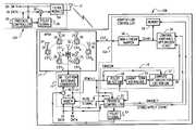
- FIG. 1is a system diagram of a communication node 10 B having an adaptive parasitic array antenna system according to an embodiment of the present invention. Also shown in FIG. 1 is another communication node 10 A that is transmitting and receiving data to and from communication node 10 B. Communication node 10 A may also include an adaptive parasitic array antenna system according to the present invention.
- the adaptive parasitic array antenna systemincludes an adaptive parasitic array antenna (“APAA”) 12 , a transceiver module 14 , and an adaptation controller (“AC”) 16 .
- the adaptation controlleris coupled between the transceiver module 14 and the APAA 12 .
- the APAA 12includes a plurality of antenna elements. At least one of the antenna elements of the APAA 12 is an “active” element that is coupled to the transceiver module 14 for receiving and transmitting data (TX Data and RX Data), and the other elements are the “parasitic” elements.
- the TX Datais provided to the transceiver module 14 for transmission through the APAA 12
- the RX Datais received by the transceiver module 14 for use by the communication node 10 B.
- the parasitic elementsare not coupled to the transceiver 14 , but, instead, are coupled to controlled impedance (CI) networks (see below), which control the coupling between the parasitic elements and the one or more active elements in order to control the antenna beam pattern.
- a received signal waveform RSW (r)is received at the transceiver 14 and supplied to the adaptation controller 16 .
- the basic purpose of the adaptation controller 16is to adaptively control the CI networks of the parasitic elements in response to the RSW (r) signal received at the one or more active elements of the APAA 12 .
- the ACperforms this adaptation function using three elements, a content-based optimization criterion computation module (CBOCCM) 18 , a control variable optimizer (CVO), and a protocol controller (PC) 22 .
- the CBOCCM 18receives the RSW (r) signal from the transceiver 14 and computes an optimization criterion (OC) based upon the content of the RSW (r) waveform.
- Examples of the types of OC that can be computed based on the content of the received waveform (r)include signal-to-noise ratio (SNR), signal to interference plus noise ratio (SINR), bit-error rate (BER), and may include any other type of criterion that relates to the signal content of the received waveform.
- SNRsignal-to-noise ratio
- SINRsignal to interference plus noise ratio
- BERbit-error rate
- control variable optimizer 20which preferably generates a normalized (e.g., a scale of 0 to 1) control variable vector CV(*), which vector includes a control variable for each of the parasitic elements of the APAA 12 .
- CV(*)a normalized (e.g., a scale of 0 to 1) control variable vector
- CV(*)a normalized (e.g., a scale of 0 to 1) control variable vector
- CV(*)e.g., a scale of 0 to 1
- CV(*)the control variables for each element would be designated CV( 1 ), CV( 2 ), . . . CV( 6 ), and the entire vector is referred to as CV(*).
- control variables CV(*)are coupled to the controlled impedance (CI) networks of the various parasitic elements of the APAA 12 , and adaptively adjust the impedance on these networks as the computed OC value changes. It is by optimizing the OC value through successive iterations of the adaptation controller that the present invention is able to operate in high interference environments.
- the protocol controller 22supervises and manages the overall operation of the adaptation controller 16 . It is also coupled to the TX Data, RX Data signals to and from the transceiver module 14 in order to control the operation of the adaptation controller under certain situations, and also in order to send signals back through the APAA 12 to another protocol controller 22 in another communication node 10 A. (The detailed operation of these elements is described in more detail below in connection with FIGS. 2-10.)
- the present inventioninvolves the integration of antennas/electro-magnetics (EM), RF electronics, software/firmware/hardware, and adaptive digital signal processing.
- EMelectromagnetic wave
- RF electronicsRF electronics
- software/firmware/hardwaresoftware/firmware/hardware
- adaptive digital signal processingThe design of this system also accommodates the nature of the radio frequency propagation environment in which it operates, which is preferably a high multi-path environment.
- the coupling coefficientscan be viewed as being analogous to the active element weighting used in a conventional beamformer.
- These coupling coefficients or weightscan be derived for the APAA by first evaluating the open-circuit impedance matrix (Z oc ) associated with the array that includes all the self and mutual impedances of the antenna elements.
- Z ocopen-circuit impedance matrix
- the weights for a parasitic arraycover a limited sub-space of values and hence, for a given number of elements, results in some reduction of performance.
- the effect of this losscan, however, be mitigated by adding additional parasitic elements to compensate for the loss.
- Performanceis also affected by element spacing in two ways. As spacing is reduced, mutual coupling effects increase, providing more control over beamformer weights. An opposing effect is that as the element spacing is reduced the correlation of the signal between elements also increases, thus reducing the performance of the beamformer. The position and number of elements should be chosen to optimize a given performance criterion.
- the terminating impedance of a parasitic elementis typically controlled by a DC biased PIN diode or other means acting as a variable RF impedance.
- a PIN diodeWith a PIN diode, the RF resistance drops with increasing forward DC bias current.
- An advantage of using a PIN diode in this applicationis that it offers very high RF linearity. Therefore, the PIN diode can be used even in transmit operation where lack of linearity would introduce undesirable radiated inter-modulation signals.
- the present inventionuses continuous control (versus open/short) for the parasitic terminating impedances (CI). This offers two advantages. First, as adaptation proceeds, the variation of weights can be smoother (due to smaller steps than open/short control permits) resulting in less chance of weight modulation increasing the bit error rate. Secondly, continuous control allows for gradient based or “hill climbing” methods of optimization to be used in the adaptive processing. Gradients can be estimated by using small perturbations in the impedance controls, which is not possible with switched open/short controls.
- a major cost benefit of the present inventionis that only a single radio transceiver 14 is connected to the active element. As a receiver, it is used to provide the conventional function of providing signal output, and also further provides the means by which an optimization criterion (OC) can be derived. The optimization criterion is used by the Adaptation Controller 16 to compute adjustments to the terminating impedances (CI) through the control variable vector CV(*). In transmit mode, the transceiver 14 acts as it would in a conventional wireless system.
- the beamformerat the front end, as in the present invention, is a step backward to earlier analog beamforming techniques.
- Such antennasemployed variable or fixed control of the amplitude and phase of the signal received by each antenna element.
- the final antenna beamwas then formed by electrically summing these weighted signals.
- the parasitic arrayachieves the beamforming in much the same was as the analog beamformer described above.
- the present inventionimplicitly influences the antenna weighting function through control of an electrical component's characteristics (one component is connected to each parasitic antenna element), and, in effect, the weighting and summing functions are performed through the electromagnetic coupling between the active and parasitic elements. In this way, considerable RF/microwave components and transmission lines required for an analog beamformer can be avoided, thus significantly lowering its cost and complexity, and profoundly lowering the cost in comparison to the all-digital approach described above.
- the adaptive processing(estimation of how to affect the antenna control elements (CI)) is still performed digitally, as it is for the conventional adaptive digital beamformer.
- the control algorithmcontrols the terminating impedances (CI) at each parasitic element rather than the amplitude and phase weightings for each element as in a conventional beamformer.
- a further advantage of the present inventionis that it effectively performs adaptive beamforming ahead of the radio transceiver 14 and thus in high co-channel interference (i.e., strong signals needing to be suppressed by the beamformer), dynamic range requirements for the receiver may be reduced, further reducing cost and complexity.
- the function of adaptive processingis to adjust the impedance controls (CI) and hence beamforming weights such that a given performance criterion (e.g., SINR, mean squared error, etc.) is optimized.
- This processmust continuously update the control vector CV(*) so as to track changes in the communications channel.
- This functionis generally performed on receive only (unless feedback from the remote receive end of the wireless link such as from 10 A is used for adaptive processing as well).
- LMSleast-mean-square
- RLSrecursive least-squares
- DIdirect matrix inversion
- the present inventionhas overcome this problem through the use of two preferred adaptation schemes, a pilot-tone based scheme (described in more detail with reference to FIG. 2 ), and a decision-directed based scheme (described in more detail with reference to FIG. 3 ). Both of these schemes provide adaptive control of the beam pattern based on the content of the received signal.
- FIG. 2is a more detailed system diagram of the communication node 10 B shown in FIG. 1 in which the adaptive parasitic array antenna system includes a preferred pilot-tone based adaptation controller 16 A. Also shown in this figure is an expanded diagram of another communication node 10 A, which may or may not include the adaptive parasitic array antenna system of the present invention, but which does include some type of antenna 32 (which could be an adaptive parasitic array antenna APAA 12 such as shown in 10 B), a transceiver module 24 , a pilot signal generator 26 , a mixer 30 , and a protocol controller 28 for at least controlling the pilot signal generator 26 .
- the communication node 10 Amay also include the APAA 12 and the Adaptation Controller 16 A similar to those shown in communication node 10 B.
- the communication node 10 Amay be a conventional wireless transceiver except that it must be capable of transmitting the pilot signal 26 and support the system protocol.
- the communication node 10 Awill transmit the pilot signal at full carrier power on start-up (listening for a response from the basestation 10 B) and transmit user data when the basestation signals it to do so with the pilot power below (e.g., 10 dB) the data carrier power.
- the protocol controller 28 in the communication node 10 Amay communicate protocol and other command and status information with the protocol controller 22 in the communication node 10 B.
- TX Data transmissions from communication node 10 Bare received by the antenna 32 of the communication node 10 A and passed onto the rest of this node as RX Data signals.
- the transmission data from this node 10 A, TX Datais mixed together with a pilot tone signal 26 by mixer 30 and transmitted via the transceiver module 24 .
- This mixed TX Data/pilot tone signalis received by the communication node 10 B, where it is received and used to adapt the included adaptive parasitic array antenna 12 so as to maximize the desired optimization criterion (OC).
- the preferred pilot-tone based system 10 Bincludes an adaptive parasitic array antenna 12 , a transceiver module 14 , and a pilot-tone based adaptation controller 16 A coupled between the transceiver module 14 and the CI inputs of the APAA 12 .
- the APAA 12includes at least one active antenna element 36 and one or more (preferably 6 to 32) parasitic antenna elements 34 which are electromagnetically-coupled to the active element 36 .
- the APAA 12 shown in FIG. 2includes 6 parasitic elements.
- all of the antenna elements 36 , 34are mounted on a single structure, such as a planar square or disk, with the single active element 36 mounted in the central portion of the structure, and the parasitic elements 38 mounted in some geometrical pattern about the center active element 36 . Note that this is just one type of structure for organizing the antennas elements 36 , 34 . They could be organized in many other types of structures and configurations depending on the application for the antenna system.
- Each of the parasitic elements 34is terminated with a controlled impedance (CI) network 38 .
- CIcontrolled impedance
- the CI networks 38include a variable impedance component, such as a PIN diode, and may include other components, such as inductors, capacitors and resistors.
- Each CI network 38includes an input for receiving a control variable voltage signal (CVT x ), where x is a numerical designation for the parasitic antenna number, such as CVT 1 for parasitic antenna number 1 and CVT 4 for parasitic antenna number 4 .
- CVT 1control variable voltage signal
- the control variable voltage CVT xis applied (either directly or indirectly through the other components) to the variable impedance component, such that the loading on the parasitic array antenna 38 can be varied by varying the level of the applied control variable voltage CVT x . In this manner, the electromagnetic coupling between the parasitic antennas 34 and the active antenna element 36 can be controlled in order to tune the beampattern of the APAA 12 .
- a tunnel diodecan be utilized in the CI networks 38 which, under certain biasing conditions, can provide an adjustable negative resistance for the parasitic terminating impedance CI. This allows the effective weights to extend over a much wider range including exceeding unity. Essentially this provides additional gain for the array. It also allows placing the tunnel diode controlled parasitic elements 34 farther from the active element 36 providing for additional spatial de-correlation. Wider separation would also allow for using many more elements.
- tunnel diodegenerally cannot handle the high level of RF power that a PIN diode can. Therefore it may be necessary to use a combination of PIN and tunnel diodes on receive and then bias the tunnel diodes off upon transmit. In such an arrangement the tunnel diodes could be arranged on the outer edge of the array geometry.
- the active element 36may be coupled to a fixed or adjustable matching network 40 in order to increase the performance of the APAA 12 .
- a fixed or adjustable matching network 40could be used in conjunction with the active element 36 .
- the transceiver module 14 for the pilot-tone based system 10 Bpreferably includes an RF to/from baseband converter 42 , a modem 44 , and a mixer 46 .
- the RF to/from baseband converter 42receives an analog RF signal from the active antenna element 36 when the system 10 B is in receive mode, and transmits an analog RF signal to the active antenna element 36 when the system 10 B is in transmit mode.
- the purpose of the converter 42is to convert the received RF signal to a received baseband signal and to convert the transmit baseband signal into an RF signal.
- the received baseband signalis termed the receive signal waveform, and is designated by RSW or (r).
- the received signal waveformis coupled to the modem circuit 44 , which demodulates the analog signal and recovers the RX Data.
- the TX Data from the communication node 10 Bis modulated by the modem circuit 44 , mixed with a pilot signal from a pilot signal generator 54 in the mixer 46 , and then passed to the RF to/from baseband converter 14 , which converts the TX signal to an appropriate RF signal frequency and applies that upconverted signal to the active antenna element 36 for propagation.
- the pilot-tone based adaptation controller 16 Apreferably includes a content-based optimization criterion computation module (CBOCCM) 18 , a control value optimizer (CVO) 20 , and a protocol controller 22 .
- the controller 16 Amay also include a pilot signal generator 54 , a non-linear mapping circuit 56 , and a local control value memory 58 .
- the CBOCCM 18 for the pilot-tone systempreferably includes a pilot tone detector circuit 48 , a short-term averaging circuit 50 , and an optimization criterion (OC) computation circuit 52 . The operation of each of these circuits is described in more detail below.
- the entire adaptation controller 16 A, and/or any of its functional components, such as the CBOCCM 18 , the CVO 20 , the PC 22 , etc.may be implemented either in hardware or software, or a combination of hardware and software.
- a DSP, FPGA, PLD, ASIC or a combination of discrete components and integrated circuitscould be utilized to enable the functionality depicted in the drawing figures.
- a software programcould be included that may be stored in an embedded memory, such as an EPROM, EEPROM, UVPROM, battery-backed RAM, etc., which, when executed by a DSP, CPU or other form of electronic controller, would implement some or all of the functions depicted in the drawings.
- a communication node 10 Awhich could be a user terminal is used to transmit user data (TX Data) for reception by a basestation communication node 10 B equipped with an adaptive parasitic array antenna system according to the present invention
- TX Datauser data
- basestation communication node 10 Bequipped with an adaptive parasitic array antenna system according to the present invention
- the inventionallows communication in both directions with an adaptive parasitic array antenna optionally used at the user terminal 10 A as well.
- the APAAreside only at the user terminal and not at the basestation.
- Mutual coupling between the parasitic elements 34 and a single active element 36provides beamforming.
- Monopoles, dipoles, or printed patchescan be used for the elements 34 , 36 .
- the mutual coupling coefficientscan be varied through the use of controllable termination impedances (CI) 38 (e.g., PIN diodes).
- CIcontrollable termination impedances
- the array beampattern as seen at the active element portis adjusted through an optimization process (as described in FIGS. 4-6) to improve system performance.
- a transmitted pilot signal 26is employed such that it can be reliably extracted on receive in the presence of noise and interference even before the array 12 has adapted.
- the pilot signal 26can be any signal (e.g., known pseudo-noise (PN) sequence) which, with processing, can be distinguished from other signals.
- PNpseudo-noise
- the pilot signal 26can be continuously added to the user terminal transmission (TX Data) with pilot signal power sufficiently below that of transmit data signal power. In this way, the pilot does not interfere with reception of user data by the basestation modem 44 in the transceiver module 14 , or use significant carrier power which may otherwise reduce the carrier power available for the user data signal.
- the systemmay transmit only the pilot signal in a short burst and then subsequently transmit the User TX Data signals.
- the pilot burstmay be transmitted about 2-10% of the time with the user data signal being transmitted 90-98% of the time.
- the adaptation controllerwould preferably operate only during the pilot signal burst, and would not necessarily further adapt during the time when the TX data is being received, although it may still do so depending upon the application.
- the active element 36 of the adaptive parasitic array antenna 12is connected to the RF up/down-converter 42 .
- the output of the RF up/down-converter 42is routed to a conventional data modem 44 for the user data function.
- the RF down-converteralso feeds the adaptation loop with the received signal waveform (r).
- This waveform (r)is fed to the CBOCCM 18 module, which provides the optimization criterion OC that is used to generate the control variables CV(*) that control the loading of the parasitics 34 , and thus the beampattern of the antenna 12 .
- the first step of the adaptation loop, pilot extraction 48is used to discriminate between desired and other signals.
- the criterion to be optimized OCcan be SINR, BER, received signal delay spread, system capacity, etc.
- the extracted pilot signalis used to estimate the desired user signal power (P d ).
- the interference plus noise power (P l )can be estimated as the difference between the total signal power and the desired user signal power.
- the optimization criterionis then computed 52 as the ratio P d /P l ). In the cases where insufficient correlation time and/or averaging is employed for reliable optimization, statistical fluctuations in the optimization criterion can be reduced through short-term averaging 50 .
- the optimization process 20adjusts the control variables CV(*) to adapt the parasitic array beampattern. It is important to note that large steps of the control variables CV(*) will perturb the output of the array (weight modulation) and can prevent the modem 44 from operating reliably.
- the optimizationis performed in two stages—acquisition followed by tracking.
- the acquisition stageis used to rapidly adapt the array to achieve performance sufficient for the modem to operate.
- a tracking stageis used to compensate for changes in the propagation channel.
- control variables CV(*)are denoted by the vector CV(*). Without loss of generality, the control variables CV(*) are normalized to lie between 0 and 1. Initially, the control variables CV(*) are set to midrange, i.e., 0.5. The system then iterates through the acquisition method as described in more detail below in connection with FIG. 5 . Further iterations of the acquisition stage proceed as described below, but only for the control variables CV(*) not changed in previous iterations—i.e., only those control variables remaining at the initial value of 0.5 are tested and potentially changed.
- control variables CV(*)are set back to the initial mid-point values and the entire acquisition stage re-started. Otherwise, the process proceeds to the tracking stage.
- the tracking stage of optimizationstarts with the control variables CV(*) set as determined by the preceding acquisition stage.
- the control variablesare individually perturbed by a prescribed step size.
- the systemwill continue in the tracking stage (as described in more detail below in connection with FIGS. 6A, 6 B) until a particular optimization criterion history variable has increased beyond a threshold parameter, meaning that the system has been operating without consistently achieving an acceptable OC value, in which case the system either returns to the acquisition stage or loads a previous set of control variables CV(*) from local memory 58 .
- the data modemcan be unmuted as soon as, or shortly after, the tracking mode is engaged.
- the normalized outputs from the CVO 20(which are preferably in the range of 0 to 1) are in the proper range for controlling the CI networks 38 , in which cases these signals CV(*) are the same as the control variable voltages CVT x , and can be fed directly from the CVO 20 to the CI networks 38 through a suitable digital-to-analog (D/A) converter.
- D/Adigital-to-analog
- the voltage range of 0 to 1 voltswill not be proper for controlling the CI networks 38 , either because the range of voltages is incorrect, or because there is a nonlinear relationship between the control voltage and the loading generated by the CI network 38 .
- a non-linear mapper circuit 56between the CVO 20 and the CI networks 38 that performs a non-linear mapping function and which also preferably includes appropriate D/A converters.
- this block 56would control both diodes such that as the control variable spans its range, the terminating impedance changes monotonically without abrupt steps due to both diodes changing jointly.
- the protocol controller 22is used to co-ordinate the actions required at both ends of the link by transmission of signaling information. This includes determining when the pilot should be transmitted at full versus reduced power, determining the time division duplexing (TDD) synchronization (if employed) and muting the modem before the system has adapted.
- the protocol controller 22is coupled to the TX/RX Data, the pilot signal generator 54 , the received signal waveform, the pilot detector 48 , and is configured to generate a mute signal to the modem 44 , an inhibit signal to the CVO circuit 20 , and a store/apply CV(*) signal to the optional memory 58 .
- the mute signalhas been discussed previously.
- the inhibit signalis applied to the CVO during data transmission.
- the store/apply CV(*) signalis an optional feature of the invention, and issued to store certain control variable vectors that are considered “good” sets of control variables for the particular environment in which the system is operating, and then to apply one or more of those stored control vectors when the optimization algorithm indicates that the system is no longer effectively optimizing the optimization criterion (OC).
- FIG. 3is a more detailed system diagram of the communication node 10 B shown in FIG. 1 in which the adaptive parasitic array antenna system includes a preferred decision-directed based adaptation controller 16 B.
- the antenna system including the decision-directed based adaptation controller 16 Bis similar in many respects to the pilot-tone based system described in FIG. 2 . Hence, the common features of these two systems will not be described in detail again with reference to FIG. 3 .
- the decision-directed systemcompares the received signal waveform (r) to a reconstructed version of the demodulated waveform (d) in order to compute the optimization criterion (OC). This is done through several blocks in the CBOCCM 18 , including a normalization block 62 , a reconstruction block 64 , a compute optimization criterion block 66 , and a short term averaging block 68 .
- the reconstructioncan be achieved in effect by re-modulation.
- the optimization criterion (OC) in the system shown in FIG. 3is based on the residual error (OC) that results from the difference between the normalized received signal waveform (output of block 62 ) and the re-modulated received data symbols (output of block 64 ).
- the re-modulated received data symbols (d)re-create an estimate of what the received signal waveform (r) would have been if only the desired signal was present, i.e., without noise or interference.
- Signal level normalization ( 62 )constrains the adaptation such that minimizing the residual error does not inadvertently minimize the total received signal waveform amplitude level.
- Statistical fluctuations in the optimization criterionare reduced through short-term averaging ( 68 ).
- the acquisition and tracking algorithms for the system shown in FIG. 3preferably operate in the same manner as those for the system shown in FIG. 2 . These algorithms are now described in more detail with reference to FIGS. 4-8.
- FIG. 4is a basic flowchart of the preferred method of operating the adaptation controller 16 A, 16 B shown in FIGS. 2 and 3, including an acquisition pass and a tracking pass.
- the methodbegins at 70 .
- the algorithminitializes several parameters, including PINSET(*), ACQ 13 COUNT, and CV(*).
- PINSET(*)is a vector (or array) of N elements, where N is the number of controlled impedance (CI) networks in the parasitic array, and hence the number of parasitic antennas 34 in the APAA 12 . Initially, all of the elements in PINSET(*) are set to 0. If, during the acquisition pass (FIG.
- a particular CI network 38is set to either its high or low limit (described below), then the PINSET(*) element for that particular CI network 38 is set to 1.
- ACQ_COUNTis a parameter that maintains a count of the times that the algorithm has progressed through the acquisition pass. This parameter is initially set to 0 since at initialization the system has not progressed through any acquisition passes.
- the CV(*) parameterhas been discussed previously.
- This vector CV(*)is output from the control value optimizer (CVO) 20 , and represents an array of N normalized values from 0 to 1, where there are N elements in the vector, one for each of the CI networks 38 . Initially, each element in the CV(*) vector is set to its midpoint value, or 0.5.
- control of the algorithmpasses to step 74 , where the control variables CV(*) are set (or output) by the CVO 20 (and thus applied to the CI networks 38 ), and the optimization criterion (OC) is computed according to the methodology described above with reference to FIGS. 2 and 3, and as described below in FIGS. 7 and 8. Note that in this initial iteration, the CV(*) vector elements are all set to 0.5. Thus, the initial OC computation is carried out on a control variable vector in which all the controlled impedance (CI) networks are set at midpoint.
- CIcontrolled impedance
- Control of the algorithmthen passes to step 76 , where the system determines whether the ACQ_COUNT variable has exceeded a predetermined limit, which is termed NLOOP_ACQ.
- NLOOP_ACQis a constant that may be altered depending on the application and environment in which the antenna system is operating, but is preferably in the range of 3-10, although other values, either higher or lower than this preferred range are possible. Since ACQ_COUNT is initially set to 0, the outcome of determination 76 is positive, and control passes to the acquisition pass, which is described in more detail below with reference to FIG. 5 . As noted below, each time the algorithm enters the acquisition pass, the ACQ_COUNT parameter is incremented by 1.
- step 74the control variable vector CV(*) is once again set, and the optimization criterion (OC) is computed.
- the determination 76will be positive, and the system will continue to loop through steps 78 , 74 and 76 .
- ACQ_COUNTis no longer less than NLOOP_ACQ , however, the determination 76 will yield a negative result, and the system will progress into the tracking pass 80 , which is described in more detail below with reference to FIG. 6 .
- the systemwill remain in the tracking pass loop 80 , 74 , 76 , until it is determined that the algorithm has been operating without consistently achieving an acceptable OC value, at which time the ACQ_COUNT variable is reset to 0 and the system reverts to the acquisition pass loop 78 , 74 , 76 .
- control variables CV(*)are varied by a relatively large amount, and preferably are varied to their limits—either 0 or 1 (i.e., step sizes of +/ ⁇ 0.5).
- the control variables CV(*)are varied by a relatively small amount, such as between 0.05 and 0.1, although other variations are certainly possible.
- FIG. 5is a flowchart of the preferred method of operating the acquisition pass 78 in the adaptation controller 16 A, 16 B shown in FIGS. 2 and 3.
- the methodbegins at 82 .
- the acquisition counter (ACQ_COUNT )is incremented by 1.
- the methodthen enters a loop (steps 86 - 106 ), which repeats NPIN times, once for each CI network 38 .
- the looping variableis designated “k”.
- the loop(steps 86 - 106 ) operates as follows. First, the method determines whether the PINSET element for the k-th CI network 38 (PINSET(k)) is set to 1. If so, then this indicates that this network 38 has already been set to either end of its control voltage range (as described below), and it should not be further perturbed in the acquisition process. If, however, PINSET(k) does not equal 1, meaning that it is still set to 0, then the method proceeds to step 92 for this particular CI network 38 .
- PINSET(k)the PINSET(k)
- CV_LOW(*)is a vector with as many elements as the vector CV(*), and is initialized to the same elements as CV(*).
- CV_HIGH(*)is a vector with as many elements as the vector CV(*), and is initialized to the same elements as CV(*).
- CV_LOW(*), CV_HIGH(*)operate like a mask so that only the vector variable of interest (i.e., the k-th variable, which is represented by CV_LOW(k) and CV_HIGH(k)) is perturbed and potentially output to the CI networks 38 as the new control variable vector.
- CV_LOW(k)is the k-th element of CV_LOW(*), and is initialized to LIMIT_LOW, which is the lowest output level of the CVO 20 block, preferably 0.
- CV_HIGH(k)is the k-th element of CV_HIGH(*), and is initialized to LIMIT_HIGH, which is the highest output level of the CVO 20 block, preferably 1.
- LIMIT_LOWis preferably 0 and LIMIT_HIGH is preferably 1, these values are arbitrary, and could be other values.
- the control variable outputs CV(*)are set equal to the values of the vector CV_LOW(*) and are output to the APAA 12 .
- the adaptation controller 16 A, 16 Bthen computes an optimization criterion (OC_LOW) based on the CV_LOW(*) vector control variables.
- the control variable outputs CV(*)are set equal to the values of the vector CV_HIGH(*) and output to the APAA 12 .
- the adaptation controller 16 A, 16 Bthen computes an optimization criterion (OC_HIGH) based on the CV_HIGH(*) vector control variables.
- step 98the method compares the values of OC_LOW and OC_HIGH . If OC_LOW is greater than OC_HIGH, then control passes to step 100 . If, however, OC_LOW is not greater than OC_HIGH, then control passes to step 102 . It should be noted here that in the preferred embodiment of the methodology a higher OC value is deemed to be a better set of control variables. The system just as easily could have been designed such that a lower OC value is indicative of a better set of control variables.
- the control vector CV(*)is set equal to CV_LOW(*)
- OCis set equal to OC_LOW
- the PINSET(k) element for this particular controlled impedance (CI) 38is set to 1 so that it will not be further perturbed during the acquisition pass.
- step 102the system compares the value of OC_HIGH to the prior value of OC multiplied by some delta value, also termed OC_DELTA. (Note that although OC_DELTA is used in both steps 100 and 102 , the actual OC_DELTA value for these two steps may be different.) If OC_HIGH is greater than the prior OC by at least the OC_DELTA amount, then the control vector (CV_HIGH(*)) that generated OC_HIGH is deemed to be a better set of control variables than CV(*), and control passes to step 104 .
- CV_HIGH(*)the control vector that generated OC_HIGH
- the control vector CV(*)is set equal to CV_HIGH(*)
- OCis set equal to OC_HIGH
- the PINSET(k) element for this particular controlled impedance (CI) 38is set to 1 so that it will not be further perturbed during the acquisition pass. Control then passes back to step 86 for the next iteration through the k controlled impedance (CI) networks 38 .
- OCoptimization criterion
- FIGS. 6is a flowchart of the preferred method of operating the tracking pass 80 in the adaptation controller 16 A, 16 B shown in FIGS. 2 and 3.
- the tracking pass 80is engaged after the system has looped through NLOOP_ACQ iterations of the acquisition pass 78 , at which point it is assumed that the array controlled impedance networks 38 are somewhat stabilized and are providing a relatively good OC value.
- the systementers 110 the tracking phase, in which more gradual (or incremental) changes are made to the CV(*) vector values, as opposed to the gross change induced during the acquisition phase 78 .
- the systementers a loop which is iterated NPIN times on the variable “k”, just as in the acquisition pass 78 and once for each of the NPIN controlled impedance (CI) 38 networks. After the NPIN iterations have taken place, the system returns 114 to the main control loop at step 74 shown in FIG. 4 .
- CV_LOW(*)is set equal to CV(*) and CV_HIGH(*) is set to CV(*).
- CV_LOW(k)which is the k-th element of the vector CV_LOW(*) is set equal to CV_LOW(k) minus CV_TRACKING_STEP. In other words, the k-th element of CV(*) minus CV_TRACKING_STEP.
- CV_TRACKING_STEPis an incremental value over which the k-th control variable will be varied up and down during each pass of the tracking phase.
- this tracking stepis a relatively small value, such as 0.05 to 0.1, although other values are certainly possible depending on the normalized range of outputs from the CVO 22 .
- CV_TRACKING_STEPmay be chose to be 0.5 to 1, whereas if the value output is from 0 to 100, the value may be 5-10.
- CV_HIGH(*)is set equal to CV(*)
- CV_HIGH(k)is set equal to CV_HIGH(k) plus CV_TRACKING_STEP. In this manner, the system is iterating the prior CV value for the k-th element of the control vector up and down by the value of the tracking step. These are the two values that will be tested for better OC convergence in the remainder of the tracking algorithm.
- step 118the system determines if CV_LOW(k) is less then LIMIT_LOW, thereby indicating an out-of-bounds condition. If so, then a condition flag (CF_LOW) is set to 0 at step 124 indicating that CV_LOW(k) has been iterated to an improper value. If, however, CV_LOW(k) is not out-of-bounds, then at step 120 the condition flag (CF_LOW) is set to 1 indicating that CV_LOW(k) has been iterated to a proper value, and control passes to step 122 .
- CF_LOWcondition flag
- control variablesare set according to CV_LOW(*), and the controller 16 A, 16 B computes the relevant optimization criterion (OC_LOW) based on the CV_LOW(*) vector.
- controlpasses to step 126 .
- step 126the system then tests whether CV_HIGH(k) is greater than LIMIT_HIGH, thereby indicating an out-of-bounds condition for this parameter. If so, then a condition flag (CF_HIGH) is set to 0 at step 132 indicating that CV_HIGH(k) has been iterated to an improper value. If, however, CV_HIGH(k) is not out-of-bounds, then at step 128 the condition flag (CF_HIGH) is set to 1 indicating that CV_HIGH(k) has been iterated to a proper value, and control passes to step 130 .
- CF_HIGHcondition flag
- control variablesare set according to CV_HIGH(*), it and the controller 16 A, 16 B computes the relevant optimization criterion (OC HIGH) based on the CV_HIGH(*) vector.
- controlpasses to step 134 .
- step 134the system then tests whether the condition flag CF_HIGH has been set equal to 1, indicating that CV_HIGH(k) was iterated to a proper value. If not, then control passes to step 142 . If so, then control passes to step 136 , where the system tests whether the condition flag CF_LOW has been set equal to 1, indicating that CV_LOW(k) was iterated to a proper value. If not, then control passes to step 140 . If so, then control passes to step 138 . The system will reach step 138 if both the CV_HIGH(k) and CV_LOW(k) parameters were iterated to proper values.
- the systemtests whether OC_HIGH is greater than OC_LOW (which is an arbitrarily chosen test for determining whether OC_HIGH is a better OC choice than OC_LOW, as discussed above.) If OC_HIGH is greater than OC_LOW, then control passes to step 140 , but if OC_HIGH is not greater than OC_LOW, then control passes to step 142 .
- step 140the system determines whether OC_HIGH is greater than the prior OC value multiplied by some delta (OC_DELTA). This is similar to steps 100 , 102 discussed above in the acquisition phase 78 , although the value of OC_DELTA may be different in the tracking phase than in the acquisition phase. If OC_HIGH is not greater than the prior OC multiplied by OC_DELTA, then control passes to step 148 .
- step 142the system determines whether OC_LOW is greater than the prior OC value multiplied by some delta (OC_DELTA). If OC_LOW is not greater than the prior OC multiplied by OC_DELTA, then control passes to step 148 . If, however, OC_LOW is greater than the prior OC multiplied by OC_DELTA, then control passes to step 146 , where the CV(*) vector is set to CV_LOW(*), and the current OC variable is set to OC_LOW. Control then passes to step 148 .
- OC_HISTORYis a tally of the number of times that the OC value failed to exceed a pre-determined threshold (termed OC_THRESHOLD) in the last OC_N_HISTORY iterations through the tracking stage.
- OC_THRESHOLDa pre-determined threshold
- the systemdetermines whether OC_HISTORY has exceeded some predetermined threshold count termed OC_THRESHOLD_COUNT. If not, meaning that the OC value has been consistently acceptable, then control passes back to step 112 , and the iterations through the main loop continue.
- step 152the system parameters CV(*), PINSET(*) and ACQ_COUNT are reset to their initial values of 0.5, 0 and 0, respectively.
- step 154a control vector (CV) that was previously stored in memory 58 will be applied as a new initial condition vector to the array.
- CVcontrol vector
- the protocol controller 22may determine that a particular set of control variables yields a particular good OC value. When this happens, the protocol controller 22 asserts the Store/Apply CV(*) line to the memory 58 and causes the then-existing control vector to be saved into memory. Then, at step 154 , the system may apply one or more of these stored control vectors in order to more quickly adapt the array 12 to a set of control variables that yield an acceptable optimization criterion.
- control variableswhen adapted, tend to lie at the limits of their range (i.e., control variables end up as a combination of 1's and 0's). When tracking the time variation of the propagation channel, control variables will swing from one limit to the another.
- FIG. 7is a flowchart of the preferred method of calculating the optimization criterion (OC) in the pilot-tone based adaptation controller 16 A shown in FIG. 2 .
- the steps shown in FIG. 7correspond to steps 74 , 94 and 96 shown in FIGS. 4 and 5.
- the methodbegins at 156 .
- the control variables CV(*)(which could be the current values of CV(*) as in step 74 , or CV_LOW(*) as in step 94 or CV_HIGH(*) as in step 96 ) are output to the array 12 and modify the impedance of the CI networks 38 .
- the corresponding received signal waveform (r)is then received from the transceiver module 14 .
- the optimization criterion OCis then computed (in the compute optimization criterion block 52 ) by dividing the V MAX value by the summation (over the k data points) of the magnitude squared of the received signal waveform at the k data points (samples). At step 168 , this OC value is then returned to the system, where it is supplied to the control variable optimizer 20 .
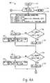
- FIG. 8is a flowchart of the preferred method of calculating the optimization criterion (OC) in the decision-directed based adaptation controller 16 B shown in FIG. 3 .
- the steps shown in FIG. 8correspond to steps 74 , 122 and 130 shown in FIGS. 4 and 6.
- the methodbegins at 170 .
- the control variables CV(*)(which could be the current values of CV(*) as in step 74 , or CV_LOW(*) as in step 122 or CV_HIGH(*) as in step 130 ) are output to the array 12 and modify the impedance of the CI networks 38 .
- the corresponding received signal waveform (r)is then received from the transceiver module 14 .
- the corresponding demodulated data symbols (d)are then received from the digital modem 60 .
- the received signal waveform (r)is then normalized, as shown in block 62 .
- an estimate of the waveform (r), termed “y”,is then reconstructed from the received data symbols (d), as shown in block 64 .
- the reconstructed waveform (y)is an estimation of what the waveform (r) would look like in the absence of any interference or noise.
- the optimization criterionis then computed as in block 66 , by calculating the magnitude squared error of (r) minus (y), termed ⁇ .
- the average value of ⁇is then calculated as in block 68 and set as the OC value.
- this OC valueis then returned to the system, where it is supplied to the control variable optimizer 20 .
- FIG. 9is an electrical schematic of the preferred controlled impedance (CI) networks 38 coupled to the parasitic elements 34 of the adaptive parasitic array antenna 12 .
- Each of the parasitic antennas 34is coupled to one of the controlled impedance (CI) networks 38 .
- the active (driven) element 36may be coupled to a matching network (MN) 40 , and from there to the transceiver module 14 .
- Each of the controlled impedance (CI) networks 38are coupled to a respective control voltage CVT x through a connector 200 .
- the controlled impedance networks (CI) 38include a resistive divider circuit 212 , 210 coupled between the control voltage input and ground, a filtering capacitor 208 coupled between the midpoint of the resistive divider circuit and ground, a blocking inductor 206 , a capacitor 202 , and a variable impedance device 204 , such as a PIN diode.
- the resistive divider 212 , 210alters the bias level of the control voltage to a level that is compatible with the variable reactance device 204 .
- the capacitor 208operates as a low pass filter in combination with the resistive divider circuit 210 , 212 .
- the inductor 206prevents RF energy from being transmitted back onto the control voltage inputs.
- the capacitor 202operates as a matching device.
- the main element of the CI network 38is the variable impedance device 204 .
- this device 204is a PIN diode.
- the voltage across the variable impedance device 204will vary, and hence the impedance (or RF loading) seen by the parasitic antenna element 34 will vary.
- the loadingmay vary between several ohms and several thousand ohms.
- the RF loading of the parasitic antenna element 34changes, so does the mutual coupling between the parasitic element 34 and the active element 36 .
- the portion of the beampattern that is associated with the mutual coupling between the particular parasitic element 34 and the active element 36is altered.
- FIG. 10is an electrical schematic of alternative controlled impedance (CI) networks 38 in which a negative resistance device 230 (TD) is used in combination with a impedance device 222 (PIN) in order to extend the beamforming capabilities of the antenna system.
- a negative resistance device 230(TD)
- PINimpedance device 222
- CVT_PIN xThe control voltage for the PIN diode
- CVT_TD xThe control voltage for the negative resistance device
- the negative resistance device 230is a tunnel diode.
- Tunnel diodesare characterized by an I—V characteristic that includes a small range of forward bias voltages over which as the voltage applied increases, the current through the device actually decreases, hence providing the negative resistance behavior.
- control variables CV(*)are input to a non-linear mapper circuit 56 , which maps the single control variable element CV(k) to a pair of control voltages CVT_PIN x and CVT_TD x for each controlled impedance (CI) network 38 . Each of these pairs of voltages is then applied to the respective CI network 38 through the connector 200 .
- the configuration of the CI network 38is similar to that described above in FIG. 9, except there are two branches to the network 38 instead of one, one branch for each of the devices 222 , 230 .
- the control voltagesare fed through an LC circuit 226 , 224 , which operates as a filter, and prevents RF energy from being transmitted back onto the control voltage inputs.
- the voltagesare then applied to the devices 222 , 230 , and matched by capacitor 220 , 228 , before being joined and connected to the parasitic antenna element 34 .
- the RF loadingconsists of the parallel combination of the PIN diode 22 and the tunnel diode 230 .
- the RF loading of the PIN diode 222 and tunnel diode 230change, thereby altering the mutual coupling between the parasitic element 34 and the active element 36 .
- the range of loadings presented to the parasitic element 34can be extended to cover from several thousand ohms (relying on the PIN diode's resistance), to several negative hundred ohms (relying on the tunnel diode's negative resistance.)
- tunnel diodesprovide several advantages. First, the extended range permits more complex beampatterns to be formed by the array 12 . Second, the effective weights associated with the parasitic elements 34 may then extend over a much wider range including exceeding unity. Essentially this provides additional gain for the array. It also allows placing the tunnel diode controlled parasitic elements 34 farther from the active element 36 providing for additional spatial de-correlation. Wider separation would also allow for the use of many more elements in the array 12 .
- the following listsincludes several optional refinements that may be implemented into the overall adaptive parasitic antenna array system: (1 ) if the transmit data rates are sufficiently high such that the system is operating in a wideband fashion, a wideband PN code, with the same bandwidth as the communication bearing signal, could be used as the pilot signal. On correlating for pilot extraction, optimum diversity combining of correlation lags (i.e., RAKE combining) can be employed to improve performance. (2) If time-domain duplexing (TDD) is employed, then during transmit, the parasitic array impedance controls are set as determined during receive optimization. (3) If TDD is employed and parasitic arrays are employed at both ends of the link they can be adapted jointly in both transmit and receive.
- TDDtime-domain duplexing
- the control values for the transmitting parasitic arraycan be perturbed and the acquisition stage repeated. This condition could be indicated to the transmitting station implicitly by its not receiving an “acquisition completed OK” acknowledgement from the receiving station within a time-out interval.
- the matching network (MN) 40can be of an electronically adjustable design. In this way, as the control variables are changed, the matching network can be adjusted as to keep the active element, as seen by the TX/RX module 14 , matched to the required impedance as much as possible.
Landscapes
- Engineering & Computer Science (AREA)
- Computer Networks & Wireless Communication (AREA)
- Signal Processing (AREA)
- Variable-Direction Aerials And Aerial Arrays (AREA)
Abstract
Description
Claims (111)
Priority Applications (2)
| Application Number | Priority Date | Filing Date | Title |
|---|---|---|---|
| US09/707,855US6492942B1 (en) | 1999-11-09 | 2000-11-07 | Content-based adaptive parasitic array antenna system |
| US10/266,128US20030048223A1 (en) | 2000-11-07 | 2002-10-07 | Content-based adaptive parasitic array antenna system |
Applications Claiming Priority (2)
| Application Number | Priority Date | Filing Date | Title |
|---|---|---|---|
| US16439799P | 1999-11-09 | 1999-11-09 | |
| US09/707,855US6492942B1 (en) | 1999-11-09 | 2000-11-07 | Content-based adaptive parasitic array antenna system |
Related Child Applications (1)
| Application Number | Title | Priority Date | Filing Date |
|---|---|---|---|
| US10/266,128ContinuationUS20030048223A1 (en) | 2000-11-07 | 2002-10-07 | Content-based adaptive parasitic array antenna system |
Publications (1)
| Publication Number | Publication Date |
|---|---|
| US6492942B1true US6492942B1 (en) | 2002-12-10 |
Family
ID=22594305
Family Applications (1)
| Application Number | Title | Priority Date | Filing Date |
|---|---|---|---|
| US09/707,855Expired - Fee RelatedUS6492942B1 (en) | 1999-11-09 | 2000-11-07 | Content-based adaptive parasitic array antenna system |
Country Status (5)
| Country | Link |
|---|---|
| US (1) | US6492942B1 (en) |
| EP (1) | EP1236243A1 (en) |
| AU (1) | AU1374301A (en) |
| CA (1) | CA2390343A1 (en) |
| WO (1) | WO2001035490A1 (en) |
Cited By (99)
| Publication number | Priority date | Publication date | Assignee | Title |
|---|---|---|---|---|
| US20020106042A1 (en)* | 2001-02-08 | 2002-08-08 | Samsung Electronics Co., Ltd. | Orthogonal frequency division multiplexing (OFDM) receiving device for forming beam with uneven width by channel property, communication device using the same, and method thereof |
| US20030002594A1 (en)* | 2001-05-31 | 2003-01-02 | Haim Harel | Communication device with smart antenna using a quality-indication signal |
| US20030030594A1 (en)* | 2001-07-30 | 2003-02-13 | Thomas Larry | Small controlled parasitic antenna system and method for controlling same to optimally improve signal quality |
| US20030090422A1 (en)* | 2001-08-31 | 2003-05-15 | Paul Diament | Systems and methods for providing optimized patch antenna excitation for mutually coupled patches |
| US20030156061A1 (en)* | 2001-11-07 | 2003-08-21 | Takashi Ohira | Method for controlling array antenna equipped with a plurality of antenna elements, method for calculating signal to noise ratio of received signal, and method for adaptively controlling radio receiver |
| US20030169760A1 (en)* | 2002-03-05 | 2003-09-11 | Kazumi Sato | Radio communication apparatus and method |
| US20030215006A1 (en)* | 2002-05-15 | 2003-11-20 | Balaji Raghothaman | Apparatus, and associated method, for facilitating antenna weight selection utilizing deterministic perturbation gradient approximation |
| WO2003098823A1 (en)* | 2002-05-15 | 2003-11-27 | Nokia Corporation | Apparatus, and associated method, for facilitating antenna weight selection utilizing deterministic perturbation gradient approximation |
| US6677898B2 (en)* | 2001-12-19 | 2004-01-13 | Advanced Telecommunications Research Institute International | Method for controlling array antenna equipped with single radiating element and a plurality of parasitic elements |
| US20040013094A1 (en)* | 2001-10-25 | 2004-01-22 | Fangwei Tong | Mobile communication terminal, and antenna array directivity-pattern-controlling method |
| US20040033818A1 (en)* | 2000-11-30 | 2004-02-19 | Hiroshi Nakamura | Mobile communication device |
| US20040036651A1 (en)* | 2002-06-05 | 2004-02-26 | Takeshi Toda | Adaptive antenna unit and terminal equipment |
| US20040043794A1 (en)* | 2002-08-30 | 2004-03-04 | Yuuta Nakaya | Radio communication apparatus |
| US20040053634A1 (en)* | 2002-05-02 | 2004-03-18 | Tantivy Communications, Inc. | Adaptive pointing for use with directional antennas operating in wireless networks |
| US20040092235A1 (en)* | 2002-11-01 | 2004-05-13 | Magnolia Broadband Inc. | Processing diversity signals using a delay |
| US20040127257A1 (en)* | 2002-12-30 | 2004-07-01 | Balaji Raghothaman | Apparatus, and associated method, for facilitating antenna weight selection utilizing deterministic perturbation gradient approximation |
| US20040139897A1 (en)* | 2003-01-10 | 2004-07-22 | Yuta Nakaya | Communications apparatus using adaptive antenna |
| US20040157567A1 (en)* | 2003-02-10 | 2004-08-12 | Jittra Jootar | Weight prediction for closed-loop mode transmit diversity |
| US20040192394A1 (en)* | 2003-01-31 | 2004-09-30 | Yuuta Nakaya | Method and apparatus for controlling array antenna, and computer-readable storage medium |
| US20050088358A1 (en)* | 2002-07-29 | 2005-04-28 | Toyon Research Corporation | Reconfigurable parasitic control for antenna arrays and subarrays |
| US20050130597A1 (en)* | 2003-12-16 | 2005-06-16 | Magnolia Broadband Inc. | Adjusting a signal at a diversity system |
| US20050164645A1 (en)* | 2004-01-26 | 2005-07-28 | Magnolia Broadband Inc. | Communicating signals according to a quality indicator using multiple antenna elements |
| US20060084388A1 (en)* | 2004-10-12 | 2006-04-20 | Qing Li | Determining a power control group boundary of a power control group |
| US20060094418A1 (en)* | 2004-11-04 | 2006-05-04 | Magnolia Broadband Inc. | Communicating signals according to a quality indicator and a time boundary indicator |
| US20060183443A1 (en)* | 2005-02-17 | 2006-08-17 | Henry Chang | Mobile station access and idle state antenna tuning systems and methods |
| US20060183442A1 (en)* | 2005-02-17 | 2006-08-17 | Henry Chang | Mobile station acquisition state antenna tuning systems and methods |
| US20060232492A1 (en)* | 2003-01-08 | 2006-10-19 | Takuma Sawatani | Array antenna control device and array antenna device |
| US20060267983A1 (en)* | 2005-05-24 | 2006-11-30 | Magnolia Broadband Inc. | Modifying a signal by adjusting the phase and amplitude of the signal |
| US20060270359A1 (en)* | 2005-05-24 | 2006-11-30 | Magnolia Broadband Inc. | Determining a phase adjustment in accordance with power trends |
| CN1309184C (en)* | 2003-07-25 | 2007-04-04 | 株式会社Ntt都科摩 | Radio receiver, radio transmitter and impedance control method |
| US20070081607A1 (en)* | 2005-10-10 | 2007-04-12 | Magnolia Broadband Inc. | Performing a scan of diversity parameter differences |
| US20070206694A1 (en)* | 2005-11-02 | 2007-09-06 | Magnolia Broadband Inc. | Modifying a signal according to a diversity parameter adjustment |
| US20070218849A1 (en)* | 2005-11-03 | 2007-09-20 | Magnolia Broadland Inc. | Amplifying a transmit signal using a fractional power amplifier |
| US20080123768A1 (en)* | 2006-10-26 | 2008-05-29 | Haim Harel | Method, system and apparatus for applying hybrid ARQ to the control of transmit diversity |
| US20080123775A1 (en)* | 2006-11-06 | 2008-05-29 | Eduardo Abreu | Modifying a signal by controlling transmit diversity parameters |
| US20080139135A1 (en)* | 2006-12-12 | 2008-06-12 | Eduardo Abreu | Method, system and apparatus for the control of transmit diversity |
| US20080150801A1 (en)* | 2006-12-26 | 2008-06-26 | Haim Harel | Method, system and apparatus for determining antenna weighting for transmit diversity |
| US20080160990A1 (en)* | 2006-12-29 | 2008-07-03 | Yair Karmi | System, method and apparatus for identification of power control using reverse rate indication |
| US20080160922A1 (en)* | 2006-12-27 | 2008-07-03 | Wei Sun | Method, system and apparatus for transmit diversity control |
| US7400692B2 (en) | 2004-01-14 | 2008-07-15 | Interdigital Technology Corporation | Telescoping window based equalization |
| US7418067B1 (en) | 2003-04-14 | 2008-08-26 | Magnolia Broadband Inc. | Processing diversity signals at a mobile device using phase adjustments |
| US20080205551A1 (en)* | 2007-02-28 | 2008-08-28 | Wai Hon Lo | Method, system and apparatus for phase control of transmit diversity signals |
| US20080214127A1 (en)* | 2007-03-01 | 2008-09-04 | Yair Karmi | Method, system and apparatus for estimation of propagation path variability of a transmit diversity channel |
| US20080227406A1 (en)* | 2007-03-15 | 2008-09-18 | Kenneth Kludt | Method and apparatus for random access channel probe initialization using transmit diversity |
| US20080227415A1 (en)* | 2007-03-14 | 2008-09-18 | Haim Harel | Method, apparatus and system for phase difference adjustment in transmit diversity |
| US20080227417A1 (en)* | 2007-03-15 | 2008-09-18 | Kenneth Kludt | Method, apparatus and system for controlling a transmit diversity device |
| US20080227405A1 (en)* | 2007-03-14 | 2008-09-18 | Haim Harel | Method, apparatus and system for providing transmit diversity feedback |
| US20080227404A1 (en)* | 2007-03-15 | 2008-09-18 | Haim Harel | Method, apparatus and system for providing feedback to a transmit diversity device |
| US20080227414A1 (en)* | 2007-03-01 | 2008-09-18 | Yair Karmi | System, method and apparatus for transmit diversity control based on variations in propagation path |
| US7437135B2 (en) | 2003-10-30 | 2008-10-14 | Interdigital Technology Corporation | Joint channel equalizer interference canceller advanced receiver |
| US20090149139A1 (en)* | 2007-12-06 | 2009-06-11 | Haim Harel | System, apparatus and method for introducing antenna pattern variability |
| US20090231196A1 (en)* | 2008-03-11 | 2009-09-17 | Huaning Niu | Mmwave wpan communication system with fast adaptive beam tracking |
| US20090284434A1 (en)* | 1998-09-21 | 2009-11-19 | Ipr Licensing, Inc. | Adaptive antenna for use in wireless communication systems |
| US7630445B1 (en) | 2005-10-25 | 2009-12-08 | Magnolia Broadband Inc. | Establishing slot boundaries of slots of a diversity control feedback signal |
| US7633905B1 (en) | 2005-09-02 | 2009-12-15 | Magnolia Broadband Inc. | Calibrating a transmit diversity communication device |
| US20100148883A1 (en)* | 2008-12-12 | 2010-06-17 | International Business Machines Corporation | Measurement and control of electromagnetic interference |
| US7783267B1 (en) | 2005-06-23 | 2010-08-24 | Magnolia Broadband Inc. | Modifying a signal in response to quality indicator availability |
| US20100266063A1 (en)* | 2002-05-09 | 2010-10-21 | Haim Harel | System, method and apparatus for mobile transmit diversity using symmetric phase difference |
| US7835702B1 (en) | 2005-09-15 | 2010-11-16 | Magnolia Broadband Inc. | Calculating a diversity parameter adjustment according to previously applied diversity parameter adjustments |
| US20110009105A1 (en)* | 2009-07-13 | 2011-01-13 | Jungwoo Lee | Self-organizing networks using directional beam antennas |
| US20110059706A1 (en)* | 2009-09-08 | 2011-03-10 | Haim Harel | System and method for adaptive beamforming for specific absorption rate control |
| US7986742B2 (en) | 2002-10-25 | 2011-07-26 | Qualcomm Incorporated | Pilots for MIMO communication system |
| US20110230227A1 (en)* | 2007-03-14 | 2011-09-22 | Haim Harel | Method, apparatus and system for providing transmit diversity feedback during soft handoff |
| WO2011163194A1 (en)* | 2010-06-22 | 2011-12-29 | Research In Motion Limited | Controlling a beamforming antenna using reconfigurable parasitic elements |
| US8134976B2 (en) | 2002-10-25 | 2012-03-13 | Qualcomm Incorporated | Channel calibration for a time division duplexed communication system |
| US8145179B2 (en) | 2002-10-25 | 2012-03-27 | Qualcomm Incorporated | Data detection and demodulation for wireless communication systems |
| US8169944B2 (en) | 2002-10-25 | 2012-05-01 | Qualcomm Incorporated | Random access for wireless multiple-access communication systems |
| US8194770B2 (en) | 2002-08-27 | 2012-06-05 | Qualcomm Incorporated | Coded MIMO systems with selective channel inversion applied per eigenmode |
| US8203978B2 (en) | 2002-10-25 | 2012-06-19 | Qualcomm Incorporated | Multi-mode terminal in a wireless MIMO system |
| US8208364B2 (en) | 2002-10-25 | 2012-06-26 | Qualcomm Incorporated | MIMO system with multiple spatial multiplexing modes |
| US8218609B2 (en) | 2002-10-25 | 2012-07-10 | Qualcomm Incorporated | Closed-loop rate control for a multi-channel communication system |
| US8320301B2 (en) | 2002-10-25 | 2012-11-27 | Qualcomm Incorporated | MIMO WLAN system |
| US8358714B2 (en) | 2005-06-16 | 2013-01-22 | Qualcomm Incorporated | Coding and modulation for multiple data streams in a communication system |
| US20130021204A1 (en)* | 2011-07-21 | 2013-01-24 | Qualcomm Incorporated | Apparatus and method for wireless network enhancement via variable down tilt |
| US8570988B2 (en) | 2002-10-25 | 2013-10-29 | Qualcomm Incorporated | Channel calibration for a time division duplexed communication system |
| US20130346590A1 (en)* | 2012-06-21 | 2013-12-26 | Adobe Systems Incorporated | Client Side Control of Adaptive Streaming |
| US8686896B2 (en) | 2011-02-11 | 2014-04-01 | Src, Inc. | Bench-top measurement method, apparatus and system for phased array radar apparatus calibration |
| US8699968B2 (en) | 2007-03-14 | 2014-04-15 | Google Inc. | Using multiple and a single feedback for UE uplink beamforming in soft handoff |
| US8704705B2 (en) | 2011-03-16 | 2014-04-22 | Src, Inc. | Radar apparatus calibration via individual radar components |
| US8731489B2 (en) | 2007-03-15 | 2014-05-20 | Google Inc. | Method and apparatus for random access channel probe initialization using transmit diversity |
| US8849222B2 (en) | 2011-02-16 | 2014-09-30 | Google Inc. | Method and device for phase adjustment based on closed-loop diversity feedback |
| US8855226B2 (en) | 2005-05-12 | 2014-10-07 | Qualcomm Incorporated | Rate selection with margin sharing |
| US8873365B2 (en) | 2002-10-25 | 2014-10-28 | Qualcomm Incorporated | Transmit diversity processing for a multi-antenna communication system |
| US8958757B2 (en) | 2010-05-10 | 2015-02-17 | Google Inc. | System, method and apparatus for mobile transmit diversity using symmetric phase difference |
| US9048913B2 (en) | 2010-07-06 | 2015-06-02 | Google Inc. | Method and apparatus for adaptive control of transmit diversity to provide operating power reduction |
| US9154274B2 (en) | 2002-10-25 | 2015-10-06 | Qualcomm Incorporated | OFDM communication system with multiple OFDM symbol sizes |
| CN105745786A (en)* | 2013-09-18 | 2016-07-06 | 国家科学研究中心 | A wave shaping device, an electronic device, and a system |
| US9473269B2 (en) | 2003-12-01 | 2016-10-18 | Qualcomm Incorporated | Method and apparatus for providing an efficient control channel structure in a wireless communication system |
| US9551785B1 (en) | 1999-04-07 | 2017-01-24 | James L. Geer | Method and apparatus for the detection of objects using electromagnetic wave attenuation patterns |
| US9967011B1 (en) | 2017-05-10 | 2018-05-08 | Elwha Llc | Admittance matrix calibration using external antennas for tunable metamaterial systems |
| US10063101B2 (en) | 2015-09-04 | 2018-08-28 | Elwha Llc | Wireless power transfer using tunable metamaterial systems and methods |
| US10075219B1 (en) | 2017-05-10 | 2018-09-11 | Elwha Llc | Admittance matrix calibration for tunable metamaterial systems |
| US10218067B2 (en)* | 2015-09-04 | 2019-02-26 | Elwha Llc | Tunable metamaterial systems and methods |
| US10236576B2 (en) | 2015-09-04 | 2019-03-19 | Elwha Llc | Wireless power transfer using tunable metamaterial systems and methods |
| US10367256B2 (en) | 2017-06-26 | 2019-07-30 | Avl Technologies, Inc. | Active electronically steered array for satellite communications |
| US10468776B2 (en)* | 2017-05-04 | 2019-11-05 | Elwha Llc | Medical applications using tunable metamaterial systems and methods |
| US20220121829A1 (en)* | 2019-02-27 | 2022-04-21 | Greenerwave | System for detecting receivers |
| US11336025B2 (en) | 2018-02-21 | 2022-05-17 | Pet Technology Limited | Antenna arrangement and associated method |
| US12160049B2 (en)* | 2022-03-02 | 2024-12-03 | United States Of America As Represented By The Secretary Of The Navy | Hybrid RF beamforming with multiport antenna with parasitic array |
Families Citing this family (4)
| Publication number | Priority date | Publication date | Assignee | Title |
|---|---|---|---|---|
| US7031652B2 (en) | 2001-02-05 | 2006-04-18 | Soma Networks, Inc. | Wireless local loop antenna |
| EP1369954A3 (en)* | 2002-06-05 | 2004-10-20 | Fujitsu Limited | Adaptive antenna unit for mobile terminal |
| EP1542311A4 (en)* | 2002-11-01 | 2011-01-05 | Fujitsu Ltd | DEVICE AND METHOD FOR CONTROLLING |
| CN103624539A (en)* | 2012-08-29 | 2014-03-12 | 深圳市云海通讯股份有限公司 | Automatic assembling technology and device of microwave filter tuning screw |
Citations (21)
| Publication number | Priority date | Publication date | Assignee | Title |
|---|---|---|---|---|
| US3560978A (en) | 1968-11-01 | 1971-02-02 | Itt | Electronically controlled antenna system |
| US3725938A (en)* | 1970-10-05 | 1973-04-03 | Sperry Rand Corp | Direction finder system |
| DE2417653A1 (en) | 1973-04-18 | 1974-10-24 | Int Standard Electric Corp | ANTENNA WITH ELECTRONIC BEAM SWIVEL |
| DE2523919A1 (en) | 1974-06-03 | 1975-12-18 | E Systems Inc | ANTENNA |
| DE3150235A1 (en) | 1981-12-18 | 1983-06-30 | Licentia Patent-Verwaltungs-Gmbh, 6000 Frankfurt | Passive radiating element |
| USH26H (en)* | 1985-06-24 | 1986-02-04 | The United States Of America As Represented By The Secretary Of The Navy | Adaptive microstrip array using parasitic elements |
| US4604628A (en) | 1983-03-11 | 1986-08-05 | Telex Communications, Inc. | Parasitic array with driven sleeve element |
| US4639914A (en) | 1984-12-06 | 1987-01-27 | At&T Bell Laboratories | Wireless PBX/LAN system with optimum combining |
| US4700197A (en)* | 1984-07-02 | 1987-10-13 | Canadian Patents & Development Ltd. | Adaptive array antenna |
| USH375H (en) | 1987-03-02 | 1987-11-03 | The United States Of America As Represented By The Secretary Of The Navy | Microstrip antenna system adaptively steerable in two dimensions |
| US4710775A (en) | 1985-09-30 | 1987-12-01 | The Boeing Company | Parasitically coupled, complementary slot-dipole antenna element |
| US4937584A (en) | 1988-12-22 | 1990-06-26 | United States Of America As Represented By The Secretary Of The Navy | Adaptive phase-shifter nulling techniques for large-aperture phases arrays |
| US5243358A (en) | 1991-07-15 | 1993-09-07 | Ball Corporation | Directional scanning circular phased array antenna |
| EP0568507A1 (en) | 1992-04-29 | 1993-11-03 | Telia Ab | Method and arrangement for reducing fading between a base station and mobile units |
| US5294939A (en) | 1991-07-15 | 1994-03-15 | Ball Corporation | Electronically reconfigurable antenna |
| WO1994028595A1 (en) | 1993-05-27 | 1994-12-08 | Griffith University | Antennas for use in portable communications devices |
| US5642353A (en) | 1991-12-12 | 1997-06-24 | Arraycomm, Incorporated | Spatial division multiple access wireless communication systems |
| US5675343A (en) | 1993-11-02 | 1997-10-07 | Thomson-Csf | Radiating-element array antenna |
| EP0812026A2 (en) | 1996-06-05 | 1997-12-10 | International Business Machines Corporation | A communication system and methods utilizing a reactively controlled directive array |
| US5914695A (en) | 1997-01-17 | 1999-06-22 | International Business Machines Corporation | Omnidirectional dipole antenna |
| US6049310A (en)* | 1997-03-18 | 2000-04-11 | Mitsubishi Denki Kabushiki Kaisha | Variable directivity antenna and method of controlling variable directivity antenna |
- 2000
- 2000-11-07USUS09/707,855patent/US6492942B1/ennot_activeExpired - Fee Related
- 2000-11-08EPEP00975699Apatent/EP1236243A1/ennot_activeWithdrawn
- 2000-11-08WOPCT/CA2000/001328patent/WO2001035490A1/ennot_activeApplication Discontinuation
- 2000-11-08AUAU13743/01Apatent/AU1374301A/ennot_activeAbandoned
- 2000-11-08CACA002390343Apatent/CA2390343A1/ennot_activeAbandoned
Patent Citations (22)
| Publication number | Priority date | Publication date | Assignee | Title |
|---|---|---|---|---|
| US3560978A (en) | 1968-11-01 | 1971-02-02 | Itt | Electronically controlled antenna system |
| US3725938A (en)* | 1970-10-05 | 1973-04-03 | Sperry Rand Corp | Direction finder system |
| DE2417653A1 (en) | 1973-04-18 | 1974-10-24 | Int Standard Electric Corp | ANTENNA WITH ELECTRONIC BEAM SWIVEL |
| DE2523919A1 (en) | 1974-06-03 | 1975-12-18 | E Systems Inc | ANTENNA |
| DE3150235A1 (en) | 1981-12-18 | 1983-06-30 | Licentia Patent-Verwaltungs-Gmbh, 6000 Frankfurt | Passive radiating element |
| US4604628A (en) | 1983-03-11 | 1986-08-05 | Telex Communications, Inc. | Parasitic array with driven sleeve element |
| US4700197A (en)* | 1984-07-02 | 1987-10-13 | Canadian Patents & Development Ltd. | Adaptive array antenna |
| US4639914A (en) | 1984-12-06 | 1987-01-27 | At&T Bell Laboratories | Wireless PBX/LAN system with optimum combining |
| USH26H (en)* | 1985-06-24 | 1986-02-04 | The United States Of America As Represented By The Secretary Of The Navy | Adaptive microstrip array using parasitic elements |
| US4710775A (en) | 1985-09-30 | 1987-12-01 | The Boeing Company | Parasitically coupled, complementary slot-dipole antenna element |
| USH375H (en) | 1987-03-02 | 1987-11-03 | The United States Of America As Represented By The Secretary Of The Navy | Microstrip antenna system adaptively steerable in two dimensions |
| US4937584A (en) | 1988-12-22 | 1990-06-26 | United States Of America As Represented By The Secretary Of The Navy | Adaptive phase-shifter nulling techniques for large-aperture phases arrays |
| US5243358A (en) | 1991-07-15 | 1993-09-07 | Ball Corporation | Directional scanning circular phased array antenna |
| US5294939A (en) | 1991-07-15 | 1994-03-15 | Ball Corporation | Electronically reconfigurable antenna |
| US5642353A (en) | 1991-12-12 | 1997-06-24 | Arraycomm, Incorporated | Spatial division multiple access wireless communication systems |
| EP0568507A1 (en) | 1992-04-29 | 1993-11-03 | Telia Ab | Method and arrangement for reducing fading between a base station and mobile units |
| WO1994028595A1 (en) | 1993-05-27 | 1994-12-08 | Griffith University | Antennas for use in portable communications devices |
| US5675343A (en) | 1993-11-02 | 1997-10-07 | Thomson-Csf | Radiating-element array antenna |
| EP0812026A2 (en) | 1996-06-05 | 1997-12-10 | International Business Machines Corporation | A communication system and methods utilizing a reactively controlled directive array |
| US5767807A (en)* | 1996-06-05 | 1998-06-16 | International Business Machines Corporation | Communication system and methods utilizing a reactively controlled directive array |
| US5914695A (en) | 1997-01-17 | 1999-06-22 | International Business Machines Corporation | Omnidirectional dipole antenna |
| US6049310A (en)* | 1997-03-18 | 2000-04-11 | Mitsubishi Denki Kabushiki Kaisha | Variable directivity antenna and method of controlling variable directivity antenna |
Non-Patent Citations (4)
| Title |
|---|
| Adachi, Fumiyuki et al., "Wideband DS-CDMA for Next-Generation Mobile Communications Systems," IEEE Communications Magazine, pp. 56-69 (eptember 1998). |
| Scott, N. L. et al, "Diversity Gain from a Single-Port Adaptive Antenna Using Switched Parasitic Elements Illustrated with a Wir and Monopole Prototype", IEEE Trans. On Antennas and Propagation, vol. 47, No. 6, 6/99, pp. 1066-1070.** |
| Scott, Neil L., et al., "Diversity Gain from a Single-Port Adaptive Antenna Using Switched Parasitic Elements Illustrated with a Wire and Monopole Prototype," IEEE Transactions on Antennas and Propagation, vol. 47, No. 6, pp. 1066-1070 (Jun. 1999). |
| Vaughan, Rodney, "Swithced Parasitic Elements for Antenna Diversity", IEEE Trans. on Antennas and Propagation, vol. 47, N 2, 2/99, pp. 399-405.** |
Cited By (197)
| Publication number | Priority date | Publication date | Assignee | Title |
|---|---|---|---|---|
| US20090284434A1 (en)* | 1998-09-21 | 2009-11-19 | Ipr Licensing, Inc. | Adaptive antenna for use in wireless communication systems |
| US9551785B1 (en) | 1999-04-07 | 2017-01-24 | James L. Geer | Method and apparatus for the detection of objects using electromagnetic wave attenuation patterns |
| US7340277B2 (en)* | 2000-11-30 | 2008-03-04 | Nec Corporation | Adaptive antenna for controlling the weighting on a plurality of antenna elements |
| US20040033818A1 (en)* | 2000-11-30 | 2004-02-19 | Hiroshi Nakamura | Mobile communication device |
| US7327797B2 (en)* | 2001-02-08 | 2008-02-05 | Bong-Wee Yu | Orthogonal frequency division multiplexing (OFDM) receiving device for forming beam with uneven width by channel property, communication device using the same, and method thereof |
| US20020106042A1 (en)* | 2001-02-08 | 2002-08-08 | Samsung Electronics Co., Ltd. | Orthogonal frequency division multiplexing (OFDM) receiving device for forming beam with uneven width by channel property, communication device using the same, and method thereof |
| US9166665B2 (en) | 2001-05-31 | 2015-10-20 | Google Inc. | System, method and apparatus for mobile transmit diversity using symmetric phase difference |
| US8634495B2 (en) | 2001-05-31 | 2014-01-21 | Google Inc. | System, method and apparatus for mobile transmit diversity using symmetric phase difference |
| US7321636B2 (en) | 2001-05-31 | 2008-01-22 | Magnolia Broadband Inc. | Communication device with smart antenna using a quality-indication signal |
| US7792207B2 (en) | 2001-05-31 | 2010-09-07 | Magnolia Broadband Inc. | Communication device with smart antenna using a quality-indication signal |
| US20030002594A1 (en)* | 2001-05-31 | 2003-01-02 | Haim Harel | Communication device with smart antenna using a quality-indication signal |
| US6876337B2 (en) | 2001-07-30 | 2005-04-05 | Toyon Research Corporation | Small controlled parasitic antenna system and method for controlling same to optimally improve signal quality |
| US20030030594A1 (en)* | 2001-07-30 | 2003-02-13 | Thomas Larry | Small controlled parasitic antenna system and method for controlling same to optimally improve signal quality |
| US20030090422A1 (en)* | 2001-08-31 | 2003-05-15 | Paul Diament | Systems and methods for providing optimized patch antenna excitation for mutually coupled patches |
| US7298329B2 (en)* | 2001-08-31 | 2007-11-20 | The Trustees Of Columbia University In The City Of New York | Systems and methods for providing optimized patch antenna excitation for mutually coupled patches |
| US6833812B2 (en)* | 2001-08-31 | 2004-12-21 | The Trustees Of Columbia University In The City Of New York | Systems and methods for providing optimized patch antenna excitation for mutually coupled patches |
| US20050093746A1 (en)* | 2001-08-31 | 2005-05-05 | Paul Diament | Systems and methods for providing optimized patch antenna excitation for mutually coupled patches |
| US7593381B2 (en)* | 2001-10-25 | 2009-09-22 | Kyocera Corporation | Mobile communication terminal, and antenna array directivity-pattern-controlling method |
| US20040013094A1 (en)* | 2001-10-25 | 2004-01-22 | Fangwei Tong | Mobile communication terminal, and antenna array directivity-pattern-controlling method |
| US20030156061A1 (en)* | 2001-11-07 | 2003-08-21 | Takashi Ohira | Method for controlling array antenna equipped with a plurality of antenna elements, method for calculating signal to noise ratio of received signal, and method for adaptively controlling radio receiver |
| US7057573B2 (en)* | 2001-11-07 | 2006-06-06 | Advanced Telecommuications Research Institute International | Method for controlling array antenna equipped with a plurality of antenna elements, method for calculating signal to noise ratio of received signal, and method for adaptively controlling radio receiver |
| US6677898B2 (en)* | 2001-12-19 | 2004-01-13 | Advanced Telecommunications Research Institute International | Method for controlling array antenna equipped with single radiating element and a plurality of parasitic elements |
| US20080113629A1 (en)* | 2002-03-05 | 2008-05-15 | Kazumi Sato | Radio communication apparatus and method |
| US7324475B2 (en)* | 2002-03-05 | 2008-01-29 | Kabushiki Kaisha Toshiba | Radio communication apparatus and method |
| US7983213B2 (en) | 2002-03-05 | 2011-07-19 | Kabushiki Kaisha Toshiba | Radio communication apparatus and method |
| US20030169760A1 (en)* | 2002-03-05 | 2003-09-11 | Kazumi Sato | Radio communication apparatus and method |
| US20040053634A1 (en)* | 2002-05-02 | 2004-03-18 | Tantivy Communications, Inc. | Adaptive pointing for use with directional antennas operating in wireless networks |
| US8249187B2 (en) | 2002-05-09 | 2012-08-21 | Google Inc. | System, method and apparatus for mobile transmit diversity using symmetric phase difference |
| US20100266063A1 (en)* | 2002-05-09 | 2010-10-21 | Haim Harel | System, method and apparatus for mobile transmit diversity using symmetric phase difference |
| US20030215006A1 (en)* | 2002-05-15 | 2003-11-20 | Balaji Raghothaman | Apparatus, and associated method, for facilitating antenna weight selection utilizing deterministic perturbation gradient approximation |
| WO2003098823A1 (en)* | 2002-05-15 | 2003-11-27 | Nokia Corporation | Apparatus, and associated method, for facilitating antenna weight selection utilizing deterministic perturbation gradient approximation |
| US6745009B2 (en)* | 2002-05-15 | 2004-06-01 | Nokia Corporation | Apparatus, and associated method, for facilitating antenna weight selection utilizing deterministic perturbation gradient approximation |
| US20040036651A1 (en)* | 2002-06-05 | 2004-02-26 | Takeshi Toda | Adaptive antenna unit and terminal equipment |
| US6961026B2 (en)* | 2002-06-05 | 2005-11-01 | Fujitsu Limited | Adaptive antenna unit and terminal equipment |
| US20050088358A1 (en)* | 2002-07-29 | 2005-04-28 | Toyon Research Corporation | Reconfigurable parasitic control for antenna arrays and subarrays |
| US7453413B2 (en) | 2002-07-29 | 2008-11-18 | Toyon Research Corporation | Reconfigurable parasitic control for antenna arrays and subarrays |
| US8194770B2 (en) | 2002-08-27 | 2012-06-05 | Qualcomm Incorporated | Coded MIMO systems with selective channel inversion applied per eigenmode |
| US20040043794A1 (en)* | 2002-08-30 | 2004-03-04 | Yuuta Nakaya | Radio communication apparatus |
| US8169944B2 (en) | 2002-10-25 | 2012-05-01 | Qualcomm Incorporated | Random access for wireless multiple-access communication systems |
| US8711763B2 (en) | 2002-10-25 | 2014-04-29 | Qualcomm Incorporated | Random access for wireless multiple-access communication systems |
| US8462643B2 (en) | 2002-10-25 | 2013-06-11 | Qualcomm Incorporated | MIMO WLAN system |
| US8483188B2 (en) | 2002-10-25 | 2013-07-09 | Qualcomm Incorporated | MIMO system with multiple spatial multiplexing modes |
| US8570988B2 (en) | 2002-10-25 | 2013-10-29 | Qualcomm Incorporated | Channel calibration for a time division duplexed communication system |
| US7986742B2 (en) | 2002-10-25 | 2011-07-26 | Qualcomm Incorporated | Pilots for MIMO communication system |
| US8355313B2 (en) | 2002-10-25 | 2013-01-15 | Qualcomm Incorporated | MIMO system with multiple spatial multiplexing modes |
| US8913529B2 (en)* | 2002-10-25 | 2014-12-16 | Qualcomm Incorporated | MIMO WLAN system |
| US8320301B2 (en) | 2002-10-25 | 2012-11-27 | Qualcomm Incorporated | MIMO WLAN system |
| US8218609B2 (en) | 2002-10-25 | 2012-07-10 | Qualcomm Incorporated | Closed-loop rate control for a multi-channel communication system |
| US8208364B2 (en) | 2002-10-25 | 2012-06-26 | Qualcomm Incorporated | MIMO system with multiple spatial multiplexing modes |
| US8134976B2 (en) | 2002-10-25 | 2012-03-13 | Qualcomm Incorporated | Channel calibration for a time division duplexed communication system |
| US8203978B2 (en) | 2002-10-25 | 2012-06-19 | Qualcomm Incorporated | Multi-mode terminal in a wireless MIMO system |
| US8873365B2 (en) | 2002-10-25 | 2014-10-28 | Qualcomm Incorporated | Transmit diversity processing for a multi-antenna communication system |
| US10382106B2 (en) | 2002-10-25 | 2019-08-13 | Qualcomm Incorporated | Pilots for MIMO communication systems |
| US9967005B2 (en) | 2002-10-25 | 2018-05-08 | Qualcomm Incorporated | Pilots for MIMO communication systems |
| US8934329B2 (en) | 2002-10-25 | 2015-01-13 | Qualcomm Incorporated | Transmit diversity processing for a multi-antenna communication system |
| US9013974B2 (en) | 2002-10-25 | 2015-04-21 | Qualcomm Incorporated | MIMO WLAN system |
| US8170513B2 (en) | 2002-10-25 | 2012-05-01 | Qualcomm Incorporated | Data detection and demodulation for wireless communication systems |
| US8750151B2 (en) | 2002-10-25 | 2014-06-10 | Qualcomm Incorporated | Channel calibration for a time division duplexed communication system |
| US9031097B2 (en) | 2002-10-25 | 2015-05-12 | Qualcomm Incorporated | MIMO system with multiple spatial multiplexing modes |
| US8145179B2 (en) | 2002-10-25 | 2012-03-27 | Qualcomm Incorporated | Data detection and demodulation for wireless communication systems |
| US9312935B2 (en) | 2002-10-25 | 2016-04-12 | Qualcomm Incorporated | Pilots for MIMO communication systems |
| US9240871B2 (en) | 2002-10-25 | 2016-01-19 | Qualcomm Incorporated | MIMO WLAN system |
| US9048892B2 (en) | 2002-10-25 | 2015-06-02 | Qualcomm Incorporated | MIMO system with multiple spatial multiplexing modes |
| US9154274B2 (en) | 2002-10-25 | 2015-10-06 | Qualcomm Incorporated | OFDM communication system with multiple OFDM symbol sizes |
| US7505741B2 (en) | 2002-11-01 | 2009-03-17 | Magnolia Broadband Inc. | Processing diversity signals using a delay |
| US20040092235A1 (en)* | 2002-11-01 | 2004-05-13 | Magnolia Broadband Inc. | Processing diversity signals using a delay |
| US20040127257A1 (en)* | 2002-12-30 | 2004-07-01 | Balaji Raghothaman | Apparatus, and associated method, for facilitating antenna weight selection utilizing deterministic perturbation gradient approximation |
| US6842632B2 (en)* | 2002-12-30 | 2005-01-11 | Nokia Corporation | Apparatus, and associated method, for facilitating antenna weight selection utilizing deterministic perturbation gradient approximation |
| EP1589610A4 (en)* | 2003-01-08 | 2007-02-14 | Atr Advanced Telecomm Res Inst | NETWORK ANTENNA CONTROL DEVICE AND NETWORK ANTENNA DEVICE |
| US7391386B2 (en) | 2003-01-08 | 2008-06-24 | Advanced Telecommunications Research Institute International | Array antenna control device and array antenna device |
| US20060232492A1 (en)* | 2003-01-08 | 2006-10-19 | Takuma Sawatani | Array antenna control device and array antenna device |
| EP1437845A3 (en)* | 2003-01-10 | 2005-08-17 | Fujitsu Limited | Communications apparatus using adaptive antenna |
| US20040139897A1 (en)* | 2003-01-10 | 2004-07-22 | Yuta Nakaya | Communications apparatus using adaptive antenna |
| US7499727B2 (en)* | 2003-01-10 | 2009-03-03 | Fujitsu Limited | Communications apparatus using adaptive antenna |
| US20040192394A1 (en)* | 2003-01-31 | 2004-09-30 | Yuuta Nakaya | Method and apparatus for controlling array antenna, and computer-readable storage medium |
| EP1443594A3 (en)* | 2003-01-31 | 2006-11-22 | Fujitsu Limited | Method and apparatus for controlling array antenna, and computer-readable storage medium |
| US7155177B2 (en)* | 2003-02-10 | 2006-12-26 | Qualcomm Incorporated | Weight prediction for closed-loop mode transmit diversity |
| US20040157567A1 (en)* | 2003-02-10 | 2004-08-12 | Jittra Jootar | Weight prediction for closed-loop mode transmit diversity |
| US7418067B1 (en) | 2003-04-14 | 2008-08-26 | Magnolia Broadband Inc. | Processing diversity signals at a mobile device using phase adjustments |
| CN1309184C (en)* | 2003-07-25 | 2007-04-04 | 株式会社Ntt都科摩 | Radio receiver, radio transmitter and impedance control method |
| US7437135B2 (en) | 2003-10-30 | 2008-10-14 | Interdigital Technology Corporation | Joint channel equalizer interference canceller advanced receiver |
| US10742358B2 (en) | 2003-12-01 | 2020-08-11 | Qualcomm Incorporated | Method and apparatus for providing an efficient control channel structure in a wireless communication system |
| US9473269B2 (en) | 2003-12-01 | 2016-10-18 | Qualcomm Incorporated | Method and apparatus for providing an efficient control channel structure in a wireless communication system |
| US9876609B2 (en) | 2003-12-01 | 2018-01-23 | Qualcomm Incorporated | Method and apparatus for providing an efficient control channel structure in a wireless communication system |
| US20050130597A1 (en)* | 2003-12-16 | 2005-06-16 | Magnolia Broadband Inc. | Adjusting a signal at a diversity system |
| US7430430B2 (en) | 2003-12-16 | 2008-09-30 | Magnolia Broadband Inc. | Adjusting a signal at a diversity system |
| US7400692B2 (en) | 2004-01-14 | 2008-07-15 | Interdigital Technology Corporation | Telescoping window based equalization |
| US7272359B2 (en) | 2004-01-26 | 2007-09-18 | Magnolia Broadband Inc. | Communicating signals according to a quality indicator using multiple antenna elements |
| US20050164645A1 (en)* | 2004-01-26 | 2005-07-28 | Magnolia Broadband Inc. | Communicating signals according to a quality indicator using multiple antenna elements |
| US7558591B2 (en) | 2004-10-12 | 2009-07-07 | Magnolia Broadband Inc. | Determining a power control group boundary of a power control group |
| US20060084388A1 (en)* | 2004-10-12 | 2006-04-20 | Qing Li | Determining a power control group boundary of a power control group |
| US7515877B2 (en) | 2004-11-04 | 2009-04-07 | Magnolia Broadband Inc. | Communicating signals according to a quality indicator and a time boundary indicator |
| US20060094418A1 (en)* | 2004-11-04 | 2006-05-04 | Magnolia Broadband Inc. | Communicating signals according to a quality indicator and a time boundary indicator |
| US20060183443A1 (en)* | 2005-02-17 | 2006-08-17 | Henry Chang | Mobile station access and idle state antenna tuning systems and methods |
| US7577411B2 (en)* | 2005-02-17 | 2009-08-18 | Kyocera Corporation | Mobile station access and idle state antenna tuning systems and methods |
| US7796963B2 (en)* | 2005-02-17 | 2010-09-14 | Kyocera Corporation | Mobile station acquisition state antenna tuning systems and methods |
| US20060183442A1 (en)* | 2005-02-17 | 2006-08-17 | Henry Chang | Mobile station acquisition state antenna tuning systems and methods |
| US8855226B2 (en) | 2005-05-12 | 2014-10-07 | Qualcomm Incorporated | Rate selection with margin sharing |
| US7616930B2 (en) | 2005-05-24 | 2009-11-10 | Magnolia Broadband Inc. | Determining a phase adjustment in accordance with power trends |
| US20060270359A1 (en)* | 2005-05-24 | 2006-11-30 | Magnolia Broadband Inc. | Determining a phase adjustment in accordance with power trends |
| US20060267983A1 (en)* | 2005-05-24 | 2006-11-30 | Magnolia Broadband Inc. | Modifying a signal by adjusting the phase and amplitude of the signal |
| US8358714B2 (en) | 2005-06-16 | 2013-01-22 | Qualcomm Incorporated | Coding and modulation for multiple data streams in a communication system |
| US7783267B1 (en) | 2005-06-23 | 2010-08-24 | Magnolia Broadband Inc. | Modifying a signal in response to quality indicator availability |
| US7633905B1 (en) | 2005-09-02 | 2009-12-15 | Magnolia Broadband Inc. | Calibrating a transmit diversity communication device |
| US7885618B1 (en) | 2005-09-02 | 2011-02-08 | Magnolia Broadband Inc. | Generating calibration data for a transmit diversity communication device |
| US7835702B1 (en) | 2005-09-15 | 2010-11-16 | Magnolia Broadband Inc. | Calculating a diversity parameter adjustment according to previously applied diversity parameter adjustments |
| US20070081607A1 (en)* | 2005-10-10 | 2007-04-12 | Magnolia Broadband Inc. | Performing a scan of diversity parameter differences |
| US7746946B2 (en) | 2005-10-10 | 2010-06-29 | Magnolia Broadband Inc. | Performing a scan of diversity parameter differences |
| US7630445B1 (en) | 2005-10-25 | 2009-12-08 | Magnolia Broadband Inc. | Establishing slot boundaries of slots of a diversity control feedback signal |
| US20070206694A1 (en)* | 2005-11-02 | 2007-09-06 | Magnolia Broadband Inc. | Modifying a signal according to a diversity parameter adjustment |
| US7796717B2 (en) | 2005-11-02 | 2010-09-14 | Magnolia Brandband Inc. | Modifying a signal according to a diversity parameter adjustment |
| US8351882B2 (en) | 2005-11-03 | 2013-01-08 | Google Inc. | Amplifying a transmit signal using a fractional power amplifier |
| US7965987B2 (en) | 2005-11-03 | 2011-06-21 | Magnolia Broadband Inc. | Amplifying a transmit signal using a fractional power amplifier |
| US20070218849A1 (en)* | 2005-11-03 | 2007-09-20 | Magnolia Broadland Inc. | Amplifying a transmit signal using a fractional power amplifier |
| US7949069B2 (en) | 2006-10-26 | 2011-05-24 | Magnolia Broadband Inc. | Method, system and apparatus for applying hybrid ARQ to the control of transmit diversity |
| US20080123768A1 (en)* | 2006-10-26 | 2008-05-29 | Haim Harel | Method, system and apparatus for applying hybrid ARQ to the control of transmit diversity |
| US8150441B2 (en) | 2006-11-06 | 2012-04-03 | Magnolia Broadband Inc. | Modifying a signal by controlling transmit diversity parameters |
| US20080123775A1 (en)* | 2006-11-06 | 2008-05-29 | Eduardo Abreu | Modifying a signal by controlling transmit diversity parameters |
| US8630678B2 (en) | 2006-11-06 | 2014-01-14 | Google Inc. | Modifying a signal by controlling transmit diversity parameters |
| US8351976B2 (en) | 2006-11-06 | 2013-01-08 | Google Inc. | Modifying a signal by controlling transmit diversity parameters |
| US9281966B2 (en) | 2006-12-12 | 2016-03-08 | Google Inc. | Method, system and apparatus for the control of transmit diversity |
| US8670455B2 (en) | 2006-12-12 | 2014-03-11 | Google Inc. | Method, system and apparatus for the control of transmit diversity |
| US20080139135A1 (en)* | 2006-12-12 | 2008-06-12 | Eduardo Abreu | Method, system and apparatus for the control of transmit diversity |
| US8199735B2 (en) | 2006-12-12 | 2012-06-12 | Google Inc. | Method, system and apparatus for the control of transmit diversity |
| US7663545B2 (en) | 2006-12-26 | 2010-02-16 | Magnolia Broadband Inc. | Method, system and apparatus for determining antenna weighting for transmit diversity |
| US20100141528A1 (en)* | 2006-12-26 | 2010-06-10 | Haim Harel | Method, system and apparatus for determining antenna weighting for transmit diversity |
| US20080150801A1 (en)* | 2006-12-26 | 2008-06-26 | Haim Harel | Method, system and apparatus for determining antenna weighting for transmit diversity |
| US8009096B2 (en) | 2006-12-26 | 2011-08-30 | Magnolia Broadband Inc. | Method, system and apparatus for determining antenna weighting for transmit diversity |
| US20080160922A1 (en)* | 2006-12-27 | 2008-07-03 | Wei Sun | Method, system and apparatus for transmit diversity control |
| US8027374B2 (en)* | 2006-12-27 | 2011-09-27 | Magnolia Broadband Inc. | Method, system and apparatus for transmit diversity control |
| US20080160990A1 (en)* | 2006-12-29 | 2008-07-03 | Yair Karmi | System, method and apparatus for identification of power control using reverse rate indication |
| US20080205551A1 (en)* | 2007-02-28 | 2008-08-28 | Wai Hon Lo | Method, system and apparatus for phase control of transmit diversity signals |
| US7869535B2 (en) | 2007-02-28 | 2011-01-11 | Magnolia Broadband Inc. | Method, system and apparatus for phase control of transmit diversity signals |
| US7991365B2 (en) | 2007-03-01 | 2011-08-02 | Magnolia Broadband Inc. | Method, system and apparatus for estimation of propagation path variability of a transmit diversity channel |
| US20080214127A1 (en)* | 2007-03-01 | 2008-09-04 | Yair Karmi | Method, system and apparatus for estimation of propagation path variability of a transmit diversity channel |
| US20080227414A1 (en)* | 2007-03-01 | 2008-09-18 | Yair Karmi | System, method and apparatus for transmit diversity control based on variations in propagation path |
| US9537544B2 (en) | 2007-03-01 | 2017-01-03 | Google Inc. | System, method and apparatus for transmit diversity control based on variations in propogation path |
| US8630595B2 (en) | 2007-03-01 | 2014-01-14 | Google Inc. | System, method and apparatus for transmit diversity control based on variations in propagation path |
| US9402237B2 (en) | 2007-03-14 | 2016-07-26 | Google Inc. | Using multiple and a single feedback for UE uplink beamforming in soft handoff |
| US20110230227A1 (en)* | 2007-03-14 | 2011-09-22 | Haim Harel | Method, apparatus and system for providing transmit diversity feedback during soft handoff |
| US20080227405A1 (en)* | 2007-03-14 | 2008-09-18 | Haim Harel | Method, apparatus and system for providing transmit diversity feedback |
| US8249528B2 (en) | 2007-03-14 | 2012-08-21 | Google Inc. | Method, apparatus and system for providing transmit diversity feedback during soft handoff |
| US8032091B2 (en) | 2007-03-14 | 2011-10-04 | Magnolia Broadband Inc. | Method, apparatus and system for providing transmit diversity feedback during soft handoff |
| US7945222B2 (en) | 2007-03-14 | 2011-05-17 | Magnolia Broadband Inc. | Method, apparatus and system for providing transmit diversity feedback |
| US20080227415A1 (en)* | 2007-03-14 | 2008-09-18 | Haim Harel | Method, apparatus and system for phase difference adjustment in transmit diversity |
| US8750811B2 (en) | 2007-03-14 | 2014-06-10 | Google Inc. | Method, apparatus and system for phase difference adjustment in transmit diversity |
| US8699968B2 (en) | 2007-03-14 | 2014-04-15 | Google Inc. | Using multiple and a single feedback for UE uplink beamforming in soft handoff |
| US8014734B2 (en) | 2007-03-15 | 2011-09-06 | Magnolia Broadband Inc. | Method, apparatus and system for controlling a transmit diversity device |
| US20080227406A1 (en)* | 2007-03-15 | 2008-09-18 | Kenneth Kludt | Method and apparatus for random access channel probe initialization using transmit diversity |
| US8731489B2 (en) | 2007-03-15 | 2014-05-20 | Google Inc. | Method and apparatus for random access channel probe initialization using transmit diversity |
| US9210672B2 (en) | 2007-03-15 | 2015-12-08 | Google Inc. | Method and apparatus for random access channel probe initialization using transmit diversity |
| US20110211648A1 (en)* | 2007-03-15 | 2011-09-01 | Haim Harel | Method, apparatus and system for providing feedback to a transmit diversity device |
| US8351866B2 (en) | 2007-03-15 | 2013-01-08 | Google Inc. | Method, apparatus and system for providing feedback to a transmit diversity device |
| US8036603B2 (en) | 2007-03-15 | 2011-10-11 | Magnolia Broadband Inc. | Method, apparatus and system for providing feedback to a transmit diversity device |
| US9065510B2 (en) | 2007-03-15 | 2015-06-23 | Google Inc. | Method, apparatus and system for providing feedback to a transmit diversity device |
| US8116693B2 (en) | 2007-03-15 | 2012-02-14 | Magnolia Broadband Inc. | Method, apparatus and system for providing feedback to a transmit diversity device |
| US8046017B2 (en) | 2007-03-15 | 2011-10-25 | Magnolia Broadband Inc. | Method and apparatus for random access channel probe initialization using transmit diversity |
| US20080227417A1 (en)* | 2007-03-15 | 2008-09-18 | Kenneth Kludt | Method, apparatus and system for controlling a transmit diversity device |
| US20080227404A1 (en)* | 2007-03-15 | 2008-09-18 | Haim Harel | Method, apparatus and system for providing feedback to a transmit diversity device |
| US20090149139A1 (en)* | 2007-12-06 | 2009-06-11 | Haim Harel | System, apparatus and method for introducing antenna pattern variability |
| US8032092B2 (en) | 2007-12-06 | 2011-10-04 | Magnolia Broadband Inc. | System, apparatus and method for introducing antenna pattern variability |
| US20090231196A1 (en)* | 2008-03-11 | 2009-09-17 | Huaning Niu | Mmwave wpan communication system with fast adaptive beam tracking |
| US8502618B2 (en) | 2008-12-12 | 2013-08-06 | International Business Machines Corporation | Measurement and control of electromagnetic interference |
| US20100148883A1 (en)* | 2008-12-12 | 2010-06-17 | International Business Machines Corporation | Measurement and control of electromagnetic interference |
| US20110009105A1 (en)* | 2009-07-13 | 2011-01-13 | Jungwoo Lee | Self-organizing networks using directional beam antennas |
| US8630596B2 (en) | 2009-09-08 | 2014-01-14 | Google Inc. | System and method for adaptive beamforming for specific absorption rate control |
| US9246216B2 (en) | 2009-09-08 | 2016-01-26 | Google Inc. | System and method for adaptive beam forming for specific absorption rate control |
| US8442457B2 (en) | 2009-09-08 | 2013-05-14 | Google Inc. | System and method for adaptive beamforming for specific absorption rate control |
| US20110059706A1 (en)* | 2009-09-08 | 2011-03-10 | Haim Harel | System and method for adaptive beamforming for specific absorption rate control |
| US8958757B2 (en) | 2010-05-10 | 2015-02-17 | Google Inc. | System, method and apparatus for mobile transmit diversity using symmetric phase difference |
| US8446318B2 (en) | 2010-06-22 | 2013-05-21 | Shirook Ali | Controlling a beamforming antenna using reconfigurable parasitic elements |
| WO2011163194A1 (en)* | 2010-06-22 | 2011-12-29 | Research In Motion Limited | Controlling a beamforming antenna using reconfigurable parasitic elements |
| US9048913B2 (en) | 2010-07-06 | 2015-06-02 | Google Inc. | Method and apparatus for adaptive control of transmit diversity to provide operating power reduction |
| US8686896B2 (en) | 2011-02-11 | 2014-04-01 | Src, Inc. | Bench-top measurement method, apparatus and system for phased array radar apparatus calibration |
| US9246570B2 (en) | 2011-02-16 | 2016-01-26 | Google Inc. | Method and device for phase adjustment based on closed-loop diversity feedback |
| US8849222B2 (en) | 2011-02-16 | 2014-09-30 | Google Inc. | Method and device for phase adjustment based on closed-loop diversity feedback |
| US8704705B2 (en) | 2011-03-16 | 2014-04-22 | Src, Inc. | Radar apparatus calibration via individual radar components |
| US9294932B2 (en)* | 2011-07-21 | 2016-03-22 | Qualcomm Incorporated | Apparatus and method for wireless network enhancement via variable down tilt |
| US20130021204A1 (en)* | 2011-07-21 | 2013-01-24 | Qualcomm Incorporated | Apparatus and method for wireless network enhancement via variable down tilt |
| US9819715B2 (en)* | 2012-06-21 | 2017-11-14 | Adobe Systems Incorporated | Client side control of adaptive streaming |
| US20130346590A1 (en)* | 2012-06-21 | 2013-12-26 | Adobe Systems Incorporated | Client Side Control of Adaptive Streaming |
| CN105745786A (en)* | 2013-09-18 | 2016-07-06 | 国家科学研究中心 | A wave shaping device, an electronic device, and a system |
| US11784732B2 (en) | 2013-09-18 | 2023-10-10 | Centre National de la Recherche Scientifique—CNRS | Wave shaping device, an electronic device, and a system |
| CN105745786B (en)* | 2013-09-18 | 2019-07-23 | 国家科学研究中心 | A kind of system including wave shaping device and electronic equipment |
| US11251886B2 (en)* | 2013-09-18 | 2022-02-15 | Centre National de la Recherche Scientifique—CNRS | Wave shaping device, an electronic device, and a system |
| US10063101B2 (en) | 2015-09-04 | 2018-08-28 | Elwha Llc | Wireless power transfer using tunable metamaterial systems and methods |
| US10218067B2 (en)* | 2015-09-04 | 2019-02-26 | Elwha Llc | Tunable metamaterial systems and methods |
| US10236576B2 (en) | 2015-09-04 | 2019-03-19 | Elwha Llc | Wireless power transfer using tunable metamaterial systems and methods |
| US10468776B2 (en)* | 2017-05-04 | 2019-11-05 | Elwha Llc | Medical applications using tunable metamaterial systems and methods |
| US10075219B1 (en) | 2017-05-10 | 2018-09-11 | Elwha Llc | Admittance matrix calibration for tunable metamaterial systems |
| US9967011B1 (en) | 2017-05-10 | 2018-05-08 | Elwha Llc | Admittance matrix calibration using external antennas for tunable metamaterial systems |
| US10910702B2 (en) | 2017-06-26 | 2021-02-02 | Avl Technologies, Inc. | Active electronically steered array for satellite communications |
| US10367256B2 (en) | 2017-06-26 | 2019-07-30 | Avl Technologies, Inc. | Active electronically steered array for satellite communications |
| US11336025B2 (en) | 2018-02-21 | 2022-05-17 | Pet Technology Limited | Antenna arrangement and associated method |
| US20220121829A1 (en)* | 2019-02-27 | 2022-04-21 | Greenerwave | System for detecting receivers |
| US11797786B2 (en)* | 2019-02-27 | 2023-10-24 | Greenerwave | System for detecting receivers |
| US12160049B2 (en)* | 2022-03-02 | 2024-12-03 | United States Of America As Represented By The Secretary Of The Navy | Hybrid RF beamforming with multiport antenna with parasitic array |
Also Published As
| Publication number | Publication date |
|---|---|
| CA2390343A1 (en) | 2001-05-17 |
| EP1236243A1 (en) | 2002-09-04 |
| AU1374301A (en) | 2001-06-06 |
| WO2001035490A1 (en) | 2001-05-17 |
Similar Documents
| Publication | Publication Date | Title |
|---|---|---|
| US6492942B1 (en) | Content-based adaptive parasitic array antenna system | |
| US20030048223A1 (en) | Content-based adaptive parasitic array antenna system | |
| US8040278B2 (en) | Adaptive antenna beamforming | |
| US7113748B2 (en) | System and method for improving polarization matching on a cellular communication forward link | |
| JP3641961B2 (en) | Wireless communication device using adaptive array antenna | |
| US6404386B1 (en) | Adaptive antenna for use in same frequency networks | |
| US8059058B2 (en) | Antenna system and method for operating an antenna system | |
| US6847832B2 (en) | System and method for providing phase matching with optimized beam widths | |
| US6738020B1 (en) | Estimation of downlink transmission parameters in a radio communications system with an adaptive antenna array | |
| US6518920B2 (en) | Adaptive antenna for use in same frequency networks | |
| US20080102760A1 (en) | Centralized wireless communication system | |
| US6657590B2 (en) | Adaptive antenna reception apparatus using reception signals by arrays antennas | |
| US20100197261A1 (en) | Wireless control subsystem for a mobile electronic device | |
| US5929811A (en) | Adaptive array with automatic loop gain control | |
| JP2006504354A (en) | Method and apparatus for adapting an antenna array using a predetermined received signal | |
| US20030151553A1 (en) | Base station, base station module and method for direction of arrival estimation | |
| CA2485097A1 (en) | Adaptive pointing for directional antennas | |
| US7206555B2 (en) | Antenna diversity system and method for operating said system | |
| US7433416B1 (en) | Method and apparatus for generating transmit adaptive antenna weights with nulling using binary gradient feedback | |
| Boyko et al. | Algorithms for multiple signals adaptive processing in radio engineering systems antenna arrays | |
| Janaswamy | Spatial Diversity for Wireless Communications | |
| Tsakalaki | Reduced-complexity wireless transceiver architectures and techniques for space-time communications | |
| Garcia et al. | Digital vs. analog coherent combining on RL-ESPAR antennas | |
| JP2003209425A (en) | Array antenna control method | |
| Crişan et al. | Antenna-based Signal Fishing |
Legal Events
| Date | Code | Title | Description |
|---|---|---|---|
| AS | Assignment | Owner name:TALARICOM, INC., CANADA Free format text:ASSIGNMENT OF ASSIGNORS INTEREST;ASSIGNOR:KEZYS, VYTAS;REEL/FRAME:011334/0770 Effective date:20001108 | |
| AS | Assignment | Owner name:COM DEV INTERNATIONAL INC., CANADA Free format text:ASSET PURCHASE AGREEMENT;ASSIGNOR:TALARICOM INC.;REEL/FRAME:012984/0080 Effective date:20020326 | |
| AS | Assignment | Owner name:CANADIAN IMPERIAL BANK OF COMMERCE, CANADA Free format text:SECURITY AGREEMENT;ASSIGNOR:COM DEVINTERNATIONAL LTD.;REEL/FRAME:014003/0862 Effective date:20021206 | |
| FEPP | Fee payment procedure | Free format text:PAYOR NUMBER ASSIGNED (ORIGINAL EVENT CODE: ASPN); ENTITY STATUS OF PATENT OWNER: LARGE ENTITY | |
| FPAY | Fee payment | Year of fee payment:4 | |
| AS | Assignment | Owner name:COM DEV LTD., CANADA Free format text:SECURITY INTEREST DISCHARGE;ASSIGNOR:CANADIAN IMPERIAL BANK OF COMMERCE;REEL/FRAME:020837/0055 Effective date:20060622 | |
| FPAY | Fee payment | Year of fee payment:8 | |
| AS | Assignment | Owner name:COM DEV INTERNATIONAL LTD., CANADA Free format text:CORRECTIVE ASSIGNMENT TO CORRECT THE ASSIGNEE NAME PREVIOUSLY RECORDED ON REEL 012984 FRAME 0080. ASSIGNOR(S) HEREBY CONFIRMS THE ASSIGNMENT PURSUANT TO ASSET PURCHASE AGREEMENT;ASSIGNOR:TALARICOM INC.;REEL/FRAME:028164/0352 Effective date:20020522 | |
| REMI | Maintenance fee reminder mailed | ||
| LAPS | Lapse for failure to pay maintenance fees | ||
| STCH | Information on status: patent discontinuation | Free format text:PATENT EXPIRED DUE TO NONPAYMENT OF MAINTENANCE FEES UNDER 37 CFR 1.362 | |
| FP | Lapsed due to failure to pay maintenance fee | Effective date:20141210 |