US6491739B1 - Air separation module using a fast start valve for fast warm up of a permeable membrane air separation module - Google Patents
Air separation module using a fast start valve for fast warm up of a permeable membrane air separation moduleDownload PDFInfo
- Publication number
- US6491739B1 US6491739B1US09/708,119US70811900AUS6491739B1US 6491739 B1US6491739 B1US 6491739B1US 70811900 AUS70811900 AUS 70811900AUS 6491739 B1US6491739 B1US 6491739B1
- Authority
- US
- United States
- Prior art keywords
- separation module
- air separation
- air
- warm
- nitrogen gas
- Prior art date
- Legal status (The legal status is an assumption and is not a legal conclusion. Google has not performed a legal analysis and makes no representation as to the accuracy of the status listed.)
- Expired - Lifetime
Links
Images


Classifications
- B—PERFORMING OPERATIONS; TRANSPORTING
- B01—PHYSICAL OR CHEMICAL PROCESSES OR APPARATUS IN GENERAL
- B01D—SEPARATION
- B01D53/00—Separation of gases or vapours; Recovering vapours of volatile solvents from gases; Chemical or biological purification of waste gases, e.g. engine exhaust gases, smoke, fumes, flue gases, aerosols
- B01D53/22—Separation of gases or vapours; Recovering vapours of volatile solvents from gases; Chemical or biological purification of waste gases, e.g. engine exhaust gases, smoke, fumes, flue gases, aerosols by diffusion
- B—PERFORMING OPERATIONS; TRANSPORTING
- B01—PHYSICAL OR CHEMICAL PROCESSES OR APPARATUS IN GENERAL
- B01D—SEPARATION
- B01D63/00—Apparatus in general for separation processes using semi-permeable membranes
- B01D63/02—Hollow fibre modules
- B01D63/032—More than two tube sheets for one bundle
- B—PERFORMING OPERATIONS; TRANSPORTING
- B64—AIRCRAFT; AVIATION; COSMONAUTICS
- B64D—EQUIPMENT FOR FITTING IN OR TO AIRCRAFT; FLIGHT SUITS; PARACHUTES; ARRANGEMENT OR MOUNTING OF POWER PLANTS OR PROPULSION TRANSMISSIONS IN AIRCRAFT
- B64D37/00—Arrangements in connection with fuel supply for power plant
- B64D37/32—Safety measures not otherwise provided for, e.g. preventing explosive conditions
- B—PERFORMING OPERATIONS; TRANSPORTING
- B01—PHYSICAL OR CHEMICAL PROCESSES OR APPARATUS IN GENERAL
- B01D—SEPARATION
- B01D2313/00—Details relating to membrane modules or apparatus
- B01D2313/18—Specific valves
- B—PERFORMING OPERATIONS; TRANSPORTING
- B01—PHYSICAL OR CHEMICAL PROCESSES OR APPARATUS IN GENERAL
- B01D—SEPARATION
- B01D2313/00—Details relating to membrane modules or apparatus
- B01D2313/22—Cooling or heating elements
- B01D2313/221—Heat exchangers
Definitions
- the present inventionrelates generally to on board inert gas generating systems, and more particularly, to an on board inert gas generating system having a fast warm up feature. Even more particularly, the present invention relates to a method and apparatus for quickly warming up a permeable membrane air separation system.
- On Board Inert Gas Generating SystemsOBIGGS
- Air Separation Modulesutilizing molecular sieve employing a pressure swing adsorption (PSA) process have been used for many years to inert the fuel tanks on aircraft such as the AH-64 helicopter, C-17 transport and the V-22 tilt-Rotor aircraft.
- PSApressure swing adsorption
- this PSA technologyuses conditioned engine bleed air at typical operating temperatures that may range from ⁇ 60 to 130 degrees F., and removes oxygen to generate nitrogen enriched air (NEA). This wide temperature range has a relatively minor impact on the performance of the PSA technology.
- the NEA product gasis used to purge the ullage space above the fuel in the fuel tanks which is initially filled with air containing oxygen at the normal concentrations of about 21% oxygen. Reducing the oxygen concentration to or below about 9% oxygen in the ullage space above the fuel in the fuel tank on the aircraft eliminates the potential for an explosion when the fuel tank is exposed to potential ignition sources such as electrical sparks or incendiary rounds.
- potential ignition sourcessuch as electrical sparks or incendiary rounds.
- the initial air temperatures received by the PSA OBIGGScan be very cold, depending upon the existing environmental conditions and how quickly warm engine bleed air is provided to the OBIGGS.
- the performance of OBIGGS employing the PSA technologyis affected relatively little by air temperature of ⁇ 60 to +130 degrees, which results in immediate, efficient generation of NEA. No warm-up or start-up time is needed.
- a newer OBIGGS ASM technologyis now being employed to generate NEA on some aircraft such as the USAF F-22, and will be employed on future aircraft such as the JSF.
- This newer technologyutilizes hollow fibers of permeable membrane (PM) which operate most efficiently at operating temperatures of about +140 to +220 degrees F.
- the inlet supply airis introduced to the inside of one end of a bundle of thousands of small hollow fibers, and oxygen permeates through the walls and is exhausted.
- the nitrogenpermeates through the hollow fibers much slower than oxygen, such that at the opposite end of the hollow fibers NEA is generated by the loss of oxygen via permeation through the permeable membrane fiber as the source gas traverses the length of each hollow fiber.
- the PM technologyhas the potential advantage of exhibiting good NEA generation rates at higher operating temperatures than the PSA OBIGGS technology. This can be particularly attractive for some applications where the preferred source of air is obtained from the aircraft engine bleed air, which is generally warmer than +220 degrees F. Less cooling of the air would be required to use the PM technology than the PSA OBIGGS technology. This reduces heat exchanger size and weight, which is an important benefit for aircraft applications.
- All OBIGGS ASMs that employ either PSA or PM technologiesutilize a flow control device to regulate the amount of NEA allowed to flow from the OBIGGS ASM.
- This flow control deviceis usually a fixed orifice that is sized to limit the NEA flow rate such that the oxygen content in the NEA product gas is limited to about 9% or less.
- PSA and PM product gas nitrogen purityis inversely proportional to the NEA product flow from the ASM.
- High NEA flow through the fibersallows less time for oxygen to permeate through the PM fiber which results in the NEA oxygen content to increase.
- a flow rate that is too highcan result in the fuel tanks having explosive combinations of oxygen and fuel vapors. Too little flow results in the desired low-oxygen content, but the low NEA flow rate can significantly delay the purging of the oxygen-laden air from the fuel tank and delay the achievement of a safe inert condition.
- PM ASMsoperate best at higher operating temperatures of +140 to +220 degrees F.
- the time to inert the fuel tanks to a safe condition quicklyis important. Waiting for the PM to reach the higher normal PM operating temperature results in a delay in reaching optimum performance and reduces the NEA generation rate available during this start-up or warm-up period.
- the PMmust be warmed up quickly or longer times to inert the fuel tanks will be required.
- Some fighter aircraft missionsrequire the aircraft to be airborne in five minutes or less; however, it can take longer than that just to warm up the PM ASM and attain near normal performance. Thus, a need exists in the art for a system capable of warming up a PM ASM in five minutes or less.
- Another object of the present inventionis to provide a PM ASM system which provides warm inlet air from the engine bleed air system into the PM ASM.
- Another object of the present inventionis to initially increase NEA flow through the PM ASM to speed up the warming of the hollow fibers in the PM.
- Yet another object of the present inventionis to provide a method and apparatus that directs a portion of the warm engine bleed air into the outer shell of the PM ASM.
- Still another object of the present inventionis to provide a method and apparatus which can utilize NEA product flow and/or engine bleed air to warm the hollow fibers of the PM separator.
- Yet another object of the present inventionis to provide NEA product gas having an oxygen content of about 9% or less in less than five minutes.
- Another object of the present inventionis to provide a permeable membrane air separation system that can be warmed up in less than five minutes.
- the present inventionis directed to an apparatus and method for warming up the PM ASM to obtain near normal performance in approximately three minutes. This compares to present performance of approximately 7.5 minutes.
- the present inventionuses a fast start valve that allows an increased flow of NEA through the PM ASM that is then directed into the outer shell of the PM ASM.
- An alternative approachaccelerates PM ASM warm up by directing a portion of the warm inlet air directly into the outer shell of the PM ASM while the normal amount of NEA is allowed to flow through the inside of the PM fibers.
- a third approachis to direct a combination of increased NEA flow and inlet airflow into the outer shell to accelerate warming of the PM ASM.
- the air separation moduleis connected to a source of warm air.
- An air separation modulehas an inlet, an outlet, an exit port and an entry point. The inlet is connected to the source of warm air.
- a valveis connected to the entry point. The valve is also connected to at least one of the exit port and the source of warm air.
- the foregoing objects of the present inventionare achieved by a method of quickly warming up an air separation module.
- Warm airis flowed through an air separation module to separate nitrogen gas therefrom.
- a portion of the separated nitrogen gasis directed to an ullage space of a fuel tank.
- a portion of the separated nitrogen gasis directed back into the air separation module.
- a method of quickly warming up an air separation moduleWarm air is flowed through an air separation module to separate nitrogen gas therefrom. A portion of the separated nitrogen gas is directed to an ullage space of a fuel tank. A portion of the separated nitrogen gas is directed back into the air separation module. A source of warm air is directed into an entry point of an air separation module. The warm air is then exhausted from the air separation module.
- the foregoing objects of the present inventionare achieved by a method of quickly warming up an air separation module.
- Warm airis flowed through an air separation module to separate nitrogen gas therefrom.
- a portion of the separated nitrogen gasis directed to an ullage space of a fuel tank.
- a portion of the separated nitrogen gasis directed back into the air separation module.
- Airis directed from a source of warm air into an entry point of an air separation module and exhausts the warm air from an exit port of the air separation module.
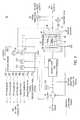
- FIG. 1is a schematic illustration of the PM OBIGGS air separation module with fast start valve that directs increased NEA flow through the PM fibers and into the PM ASM outer shell;
- FIG. 2is a schematic illustration of the PM OBIGGS ASM with a fast start valve that directs warm inlet air into the outer shell of the PM ASM;
- FIG. 3is a schematic illustration of the PM OBIGGS ASM with a fast start valve that directs a combination increased NEA flow and warm inlet air into the PM ASM outer shell;
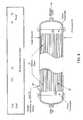
- FIG. 4is a cross-sectional schematic of the PM OBIGGS ASM.
- FIG. 1is a schematic illustration of OBIGGS ASM, generally depicted at 10 , and includes optional communication interfaces that allow an aircraft computer to monitor and control the operation of the OBIGGS.
- the OBIGGS control autonomycould range from all aircraft to all self-contained, depending on program requirements.
- Source-air 12 from an engine compressor and heat exchanger, environmental control system (ECS), or mechanically driven compressoris introduced to a PM separator 20 through an inlet air coalescing filter 14 .
- An optional exterior insulating shell 26 (FIGS. 1-3) surrounding the PM separator 20can be used if needed to help maintain the preferred operating temperature of the PM separator 20 .
- the coalescing filter 14removes excess water and other condensed contaminants and vents the contaminants overboard through a vent 16 .
- the filtered airis then directed to an isolation valve and optional pressure reducer 18 that can close and prevent air from entering the PM separator 20 when required.
- the isolation valve and optional pressure reducer 18reduces the downstream pressure during normal operation to reduce the ASM component structures required to withstand proof and burst pressures, and/or to limit air consumption rate as system requirements dictate.
- the reduced pressure airthen flows into the PM separator 20 where oxygen and water vapor permeate through the walls of the hollow fiber membranes 22 and are vented overboard through the vent 16 , which is also connected to an outlet port 54 (FIG. 4) formed in an outer shell 50 of the PM separator 20 .
- the NEA productflows through the PM separator 20 and through the hollow membranes 22 to one of three possible outlet flow paths. During normal or steady state operation, a first flow path 24 is used.
- the first flow pathexits the PM separator 20 through a nitrogen outlet 56 located at one end of the PM separator 20 .
- the first flow path 24 for the NEA product gasis the normal flow path to the aircraft plumbing which normally includes a NEA pressure reducing valve or fixed flow controlling orifice (not shown) and additional aircraft plumbing to each fuel tank (not shown).
- the second flow pathis to and through an optional ullage wash valve 60 that can be activated as needed to provide an increased NEA flow to the fuel tank ullage to more quickly flush the ullage of oxygen laden air during the initial period of inerting the fuel tanks. This ullage wash valve 60 can be used to reduce the initial time to inert the fuel tanks.
- the ullage wash valve 60can be closed, and the first flow path 24 continues to provide NEA flow to the tanks to maintain the inert condition as the fuel is consumed.
- the ullage wash valve 60can be activated during aircraft descents to provide the higher NEA flow rates required to equalize the internal fuel tank pressure with the increasing surrounding atmospheric air pressure. This can prevent atmospheric air from entering the tanks during the aircraft descent to lower altitudes, which can cause the fuel tanks to acquire an explosive air-fuel ratio.
- the second flow pathis from the first flow path 24 to the ullage wash valve 60 . Thus, a portion of the NEA product gas is redirected to the ullage wash valve 60 .
- the third flow pathis to and through the fast start valve 40 , and through an orifice 41 into an entry point 42 formed into the outer shell 50 of the ASM 20 .
- This fast start valve 40is opened during the first few minutes of operation to provide accelerated warming of the PM ASM by increasing the flow of warming inlet air and of NEA from the PM 20 above the normal flow. This accelerates the flow of warm source air into and through the PM separator 20 and shortens warm-up time and the time to inert the fuel tanks.
- the flow of NEA through the fast start valve 40is directed through an entry point 42 into the outer shell 50 and around the hollow fibers 22 and through a flow-limiting orifice 41 to further enhance initial ASM warming.
- This fast start NEA flow through the outer shell 50 and around the outer surfaces of the hollow fibers 22is combined with ASM permeate and the contaminants from the coalescing filter drain, and vented overboard through an outlet 54 (see FIG. 4) and through the vent 16 .
- FIG. 4shows one of the possible combinations of entry point 42 and vent 16 . These positions may vary depending on the system packaging design requirements.
- This fast start valve 40can be activated for a predetermined period of time or until the PM ASM temperature is reached as measured by a temperature sensor located in the PM separator 20 or outlet flow plumbing. Alternately, the fast start valve 40 could utilize a variable flow control area that is adjusted as a function of time or temperature to further optimize the warming effect.
- the ASM 20includes an OBIGGS monitor 100 that checks and reports critical operating parameters to a self-contained computer or to the aircraft computer that analyzes the data and controls the OBIGGS operation through the OBIGGS monitor interface 102 .
- the monitor 100is electrically powered.
- the monitor 100includes an oxygen sensor 110 that measures the oxygen content of the NEA product gas and reports it to the aircraft computer.
- the monitor 100also includes transducers for measurement and reporting of the pressures upstream 114 and downstream 112 of the coalescing filter 14 , and downstream 116 of the PM separator 20 .
- the inlet air temperatureis also measured by a thermocouple 120 and reported to the controlling computer. This information is monitored by the aircraft computer, which initiates appropriate actions to the ASM through the OBIGGS monitor 102 , and indicates when maintenance actions are required.
- the first flow path 24is always open to let NEA to continuously flush oxygen from the ullage.
- the ullage wash valve 60is opened for additional flow to accelerate O 2 removal for a time interval, or until the aircraft reaches specific altitude, or until the tank is sensed to be safe by an external oxygen sensor located in the fuel tank (not shown).
- a thermocouple (TC 1 ) 120is used to monitor the air temperature exiting the filter 14 .
- the optional communication interfaces between the OBIGGS monitor 100 and the aircraft computersinclude a PT 3 analog out line 130 , a PT 2 analog out line 132 , a PT 1 analog out line 134 , an 02 analog out line 136 , a monitor fault line 138 , a temperature (TC 1 ) analog out line 140 , a ullage wash valve control 142 , and an OBIGGS isolation valve control 144 . It is readily apparent that these analog signals could also be digital signals, depending upon the desired system architecture.
- the monitor 100controls the fast start valve 40 electrically, or pneumatically with pilot control pressure from a solenoid valve.
- the monitor 100controls the isolation valve and pressure reducer 18 electrically or pneumatically.
- the monitor 100also controls the ullage wash valve 60 electrically or pneumatically.
- the OBIGGS monitor 100receives pneumatic pressure from each of the three pneumatic lines that provide pressure signals from each of the three pressure transducers 112 , 114 , and 116 .
- the fast start valve 40is opened during warm-up until the operating temperature of the hollow fibers 22 are between +140 and +220 degrees F. This temperature can be measured using a thermocouple (not shown) in the outlet path 24 .
- the NEA flowwill exit the PM separator 20 through outlet path 24 and be redirected through the fast start valve 40 into orifice 41 and then through the entry point 42 .
- the orifice 306 and the check valve 302are located in line 200 and the orifice 304 and the check valve 300 are located in a line 202 connecting the outlet path 24 of the inlet of the fast start valve 40 .
- the check valve 300prevents warm engine bleed air from mixing with the NEA output and the check valve 302 prevents NEA output from flowing back to the inlet of the PM separator 20 .
- the third embodimentprovides the fastest warm up because both warm engine air and NEA product are used to heat the hollow fibers 22 .
- the entry point 42is located as far from the exit 54 to allow maximum heat exchange time and surface area to warm the outer surfaces of the hollow fibers 22 .
- FIG. 2shows an alternate approach that directs warm inlet air directly into the PM ASM shell 50 before passing through the PM separator for the purpose of accelerating the warming of the hollow membrane fibers 22 .
- FIG. 2is identical to FIG. 1 except that output line 24 is not connected to fast start valve 40 but instead a separate and different line 198 that connects the outlet of the isolation valve and optional pressure reducer 18 to the inlet of the fast start valve 40 .
- This approachuses inlet air directly for warming the PM ASM instead of using the increased NEA product flow during the warm up period.
- a portion of the warmer engine bleed airis directed from the outlet of the isolation valve 18 to the fast start valve 40 and through orifice 41 .
- the warm engine bleed airthen enters the PM separator 20 through the entry point 42 .
- This approachspeeds up the warming of the hollow fibers 22 in the PM separator.
- the product NEA gasflows to either the first or second flow path described previously.
- FIG. 3A third embodiment is shown in FIG. 3, where the inlet air and NEA product gases are combined together and directed into the ASM shell to accelerate warming of the PM hollow fibers.
- the preferred embodimentis depicted in FIG. 3, which is a combination of FIGS. 1 and 2 and enables the greatest flexibility in optimizing the system performance for a variety of OBIGGS applications.
- Check valves 300 , 302are added to prevent mixing of the air and NEA gases.
- Flow control orifices 304 , 306are included to control gas flow rates from each source to allow optimization of the system operating parameters as they are affected by source air availability, warm up time allowed, NEA purity, NEA flow rates and other requirements.
- the hollow fibers 22are sandwiched between a first epoxy tubesheet 100 and a second epoxy tubesheet 102 .
- An inlet end of each of the hollow fibers 22is in contact with one surface of the first epoxy tubesheet and an opposite end of each of the hollow fibers 22 is in contact with one surface of the second epoxy tubesheet.
- the entry point 42is located near the second epoxy tubesheet 102 and the exit port 54 is located near the first epoxy tubesheet 100 .
- the first and second epoxy tubesheets 100 , 102permit flow of the inlet air and the nitrogen output, respectively.
Landscapes
- Chemical & Material Sciences (AREA)
- Chemical Kinetics & Catalysis (AREA)
- Engineering & Computer Science (AREA)
- Aviation & Aerospace Engineering (AREA)
- Analytical Chemistry (AREA)
- General Chemical & Material Sciences (AREA)
- Oil, Petroleum & Natural Gas (AREA)
- Separation Using Semi-Permeable Membranes (AREA)
- Infusion, Injection, And Reservoir Apparatuses (AREA)
Abstract
Description
Claims (23)
Priority Applications (7)
| Application Number | Priority Date | Filing Date | Title |
|---|---|---|---|
| US09/708,119US6491739B1 (en) | 1999-11-09 | 2000-11-08 | Air separation module using a fast start valve for fast warm up of a permeable membrane air separation module |
| JP2000342499AJP4605892B2 (en) | 1999-11-09 | 2000-11-09 | Air separation module assembly and high speed warm-up method of air separation module |
| AT00124533TATE439902T1 (en) | 1999-11-09 | 2000-11-09 | AIR SEPARATION DEVICE WITH QUICK START VALVE FOR QUICKLY HEATING UP THE PERMEABLE MEMBRANE |
| EP00124533AEP1108458B1 (en) | 1999-11-09 | 2000-11-09 | Air separation module using a fast start valve for fast warm up of the permeable membrane |
| DE60042774TDE60042774D1 (en) | 1999-11-09 | 2000-11-09 | Air separation device with quick-start valve for quick warm-up of the permeable membrane |
| KR1020000066508AKR20010060285A (en) | 1999-11-09 | 2000-11-09 | Air separation module using fast start valve for fast warm up of a permeable membrane air separation module |
| CA002325299ACA2325299C (en) | 1999-11-09 | 2000-11-09 | Air separation module using a fast start valve for fast warm up of a permeable membrane separation module |
Applications Claiming Priority (2)
| Application Number | Priority Date | Filing Date | Title |
|---|---|---|---|
| US16434099P | 1999-11-09 | 1999-11-09 | |
| US09/708,119US6491739B1 (en) | 1999-11-09 | 2000-11-08 | Air separation module using a fast start valve for fast warm up of a permeable membrane air separation module |
Publications (1)
| Publication Number | Publication Date |
|---|---|
| US6491739B1true US6491739B1 (en) | 2002-12-10 |
Family
ID=26860464
Family Applications (1)
| Application Number | Title | Priority Date | Filing Date |
|---|---|---|---|
| US09/708,119Expired - LifetimeUS6491739B1 (en) | 1999-11-09 | 2000-11-08 | Air separation module using a fast start valve for fast warm up of a permeable membrane air separation module |
Country Status (7)
| Country | Link |
|---|---|
| US (1) | US6491739B1 (en) |
| EP (1) | EP1108458B1 (en) |
| JP (1) | JP4605892B2 (en) |
| KR (1) | KR20010060285A (en) |
| AT (1) | ATE439902T1 (en) |
| CA (1) | CA2325299C (en) |
| DE (1) | DE60042774D1 (en) |
Cited By (35)
| Publication number | Priority date | Publication date | Assignee | Title |
|---|---|---|---|---|
| US20040065778A1 (en)* | 2002-10-04 | 2004-04-08 | Jones Philip E. | Increasing the performance of aircraft on-board inert gas generating systems by turbocharging |
| US20040112211A1 (en)* | 2002-11-26 | 2004-06-17 | Udi Meirav | Oxygen enrichment of indoor human environments |
| US20040226438A1 (en)* | 2003-03-07 | 2004-11-18 | Jones Philip E. | Cooling system for an on-board inert gas generating system |
| US20040238691A1 (en)* | 2003-05-28 | 2004-12-02 | Harold Hipsky | Compressor for use in aircraft fuel tank air purge system |
| US20050092177A1 (en)* | 2003-09-22 | 2005-05-05 | Bonchonsky Michael J. | Air separation system and method with modulated warming flow |
| US20050115404A1 (en)* | 2003-12-02 | 2005-06-02 | Honeywell International Inc. | Gas generating system and method for inerting aircraft fuel tanks |
| US20050223895A1 (en)* | 2004-04-08 | 2005-10-13 | Wong Kenneth K | Utilization of compressor surge control air in an aircraft on-board inert gas generating system |
| US20050235659A1 (en)* | 2004-03-03 | 2005-10-27 | Norbert Brutscher | System for the preparation of compressed air |
| US20060000357A1 (en)* | 2004-03-23 | 2006-01-05 | Keith Michael | Method and system for producing inert gas from combustion by-products |
| US20060151670A1 (en)* | 2004-02-10 | 2006-07-13 | Loss Kevin L | Methods and systems for controlling flammability control systems in aircraft and other vehicles |
| US20060230935A1 (en)* | 2004-03-23 | 2006-10-19 | Keith Michael | Method and system for producing inert gas from combustion by-products |
| US20070245802A1 (en)* | 2006-04-25 | 2007-10-25 | Howard Austerlitz | Asm output ultrasonic oxygen sensor |
| US20080060523A1 (en)* | 2006-09-12 | 2008-03-13 | Honeywell International Inc. | Enhanced obiggs |
| US20090246429A1 (en)* | 2008-04-01 | 2009-10-01 | Rehan Zaki | Filled epoxy tubesheet |
| US20090249808A1 (en)* | 2008-04-08 | 2009-10-08 | Ullman Alan Z | Evaporative Cooling for an Aircraft Subsystem |
| US20100064886A1 (en)* | 2008-09-12 | 2010-03-18 | Eric Surawski | On-board inert gas generation system with air separation module temperature control |
| US20100263537A1 (en)* | 2009-04-17 | 2010-10-21 | William Joseph Beeson | Heated blanket for air separation module |
| CN102527241A (en)* | 2010-11-04 | 2012-07-04 | 宇部兴产株式会社 | Gas separation membrane assembly and gas separation method |
| JP2012532749A (en)* | 2009-07-09 | 2012-12-20 | カールトン・ライフ・サポート・システムズ・インコーポレイテッド | Heat regulation for air separation module |
| CN101767652B (en)* | 2009-12-30 | 2013-01-09 | 南京航空航天大学 | Fuel washing device for aircraft refueling vehicle |
| US20140083511A1 (en)* | 2012-09-27 | 2014-03-27 | Khem Vanwijak Eowsakul | Nitrogen gas system with diverter valve |
| US8778062B1 (en)* | 2011-12-15 | 2014-07-15 | The Boeing Company | Warming system for air separation modules |
| US9120571B2 (en) | 2012-05-25 | 2015-09-01 | B/E Aerospace, Inc. | Hybrid on-board generation of oxygen for aircraft passengers |
| WO2016038138A1 (en)* | 2014-09-12 | 2016-03-17 | Eaton Limited | Fluid separation module for use in aircrafts |
| RU2578901C1 (en)* | 2014-11-18 | 2016-03-27 | Публичное акционерное общество "Научно-производственная корпорация "Иркут" | Passenger aircraft neutral gas system |
| US20160107116A1 (en)* | 2014-10-15 | 2016-04-21 | Parker-Hannifin Corporation | Obiggs asm performance modulation via temperature control |
| US9550575B2 (en) | 2012-05-25 | 2017-01-24 | B/E Aerospace, Inc. | On-board generation of oxygen for aircraft pilots |
| US9550570B2 (en) | 2012-05-25 | 2017-01-24 | B/E Aerospace, Inc. | On-board generation of oxygen for aircraft passengers |
| US9718023B2 (en) | 2010-11-04 | 2017-08-01 | Ube Industries, Ltd. | Gas separation membrane module and gas separation method |
| WO2017180840A1 (en) | 2016-04-13 | 2017-10-19 | Carleton Life Support Systems, Inc. | On-board inert gas generating system prognostic health monitoring |
| US9802159B2 (en) | 2015-07-09 | 2017-10-31 | Hamilton Sundstrand Corporation | Air separation module canister |
| US9900637B2 (en) | 2013-11-20 | 2018-02-20 | Mitsubishi Electric Corporation | Wireless communication system, transmission device, reception device, and communication terminal |
| CN107856869A (en)* | 2017-12-08 | 2018-03-30 | 南京航空航天大学 | A kind of catalysis burning inerting aircraft fuel tank system and control method with tonifying Qi |
| US10137406B2 (en) | 2015-06-11 | 2018-11-27 | Hamilton Sundstrand Corporation | Temperature controlled nitrogen generation system |
| CN109625298A (en)* | 2018-12-07 | 2019-04-16 | 中国航空工业集团公司西安飞机设计研究所 | A kind of oil gas isolating device and the aircraft with it |
Families Citing this family (15)
| Publication number | Priority date | Publication date | Assignee | Title |
|---|---|---|---|---|
| GB2397303B (en) | 2003-01-17 | 2007-04-04 | Smartmembrane Corp | Gas separation membranes |
| GB2397821B (en)* | 2003-01-30 | 2006-04-05 | Smartmembrane Corp | Oxygen and nitrogen enriched atmospheres in aircraft |
| US7152635B2 (en)* | 2004-02-10 | 2006-12-26 | The Boeing Company | Commercial aircraft on-board inerting system |
| DE102004039667A1 (en) | 2004-08-16 | 2006-03-02 | Airbus Deutschland Gmbh | Air supply device for gas generating system in aircraft, supplies bleeding air from air generation system heat exchanger to on-board inert gas generation system |
| WO2006122282A2 (en)* | 2005-05-11 | 2006-11-16 | Innovative Solutions & Support, Inc. | Pressure-based aircraft fuel capacity monitoring system and method |
| WO2008094990A1 (en) | 2007-01-31 | 2008-08-07 | Flair Corporation | Integral sweep controller for gas membrane separation device |
| EP2717998B1 (en)* | 2011-06-08 | 2020-09-23 | The Boeing Company | Fluid separation assembly and method |
| US9566553B2 (en) | 2011-06-08 | 2017-02-14 | The Boeing Company | Fluid separation assembly and method |
| US9084962B2 (en)* | 2011-06-08 | 2015-07-21 | The Boeing Company | Fluid separation assembly and method |
| WO2012170956A1 (en)* | 2011-06-08 | 2012-12-13 | Benjamin Bikson | Hollow fiber apparatus and use thereof for fluids separations and heat and mass transfers |
| PL3102313T3 (en)* | 2014-02-03 | 2021-10-25 | Eurosider S.A.S. Di Milli Ottavio & C. | Module for separating nitrogen with hollow-fibre membrane |
| FR3018460B1 (en)* | 2014-03-11 | 2017-10-27 | Air Liquide | DEVICE FOR SEPARATING GAS AND AIRCRAFT PROVIDED WITH SUCH A DEVICE |
| US9827530B2 (en) | 2015-01-30 | 2017-11-28 | Hamilton Sundstrand Corporation | Enhanced device for separation of oxygen and nitrogen |
| KR102331446B1 (en)* | 2016-04-20 | 2021-11-26 | 칼튼 라이프 서포트 시스템즈, 아이엔씨. | On-board inert gas generating air separation module restoration device and method |
| FR3061774B1 (en) | 2017-01-09 | 2021-10-08 | Zodiac Aerotechnics | DEVICE FOR MEASURING THE QUANTITY OF OXYGEN PRESENT IN A GAS, AND AIR SEPARATION MODULE INCLUDING SUCH A MEASURING DEVICE |
Citations (22)
| Publication number | Priority date | Publication date | Assignee | Title |
|---|---|---|---|---|
| US4378920A (en) | 1980-07-15 | 1983-04-05 | The Boeing Company | Combustibly inert air supply system and method |
| US4508548A (en) | 1981-08-04 | 1985-04-02 | The Garrett Corporation | Air oxygen and nitrogen concentration device |
| JPS60169662A (en)* | 1984-02-15 | 1985-09-03 | Nippon Denso Co Ltd | Exhaust suppression device for vaporized fuel |
| US4681602A (en) | 1984-12-24 | 1987-07-21 | The Boeing Company | Integrated system for generating inert gas and breathing gas on aircraft |
| US4718921A (en)* | 1986-10-08 | 1988-01-12 | Ube Industries, Ltd. | Method for removing water vapor from water vapor-containing gas |
| US4857082A (en)* | 1988-09-15 | 1989-08-15 | Air Products And Chemicals, Inc. | Membrane unit turn-down control system |
| US5030251A (en)* | 1989-10-30 | 1991-07-09 | Permea, Inc. | System and method for separating a portion of a gas from a mixture of gases |
| US5053058A (en)* | 1989-12-29 | 1991-10-01 | Uop | Control process and apparatus for membrane separation systems |
| US5069692A (en) | 1989-12-11 | 1991-12-03 | Sundstrand Corporation | Fully integrated inert gas and oxidizer replenishment system |
| US5226931A (en)* | 1991-10-24 | 1993-07-13 | Canadian Liquid Air Ltd. -Air Liquide Canada Ltee. | Process for supplying nitrogen from an on-site plant |
| US5226932A (en)* | 1991-10-07 | 1993-07-13 | Praxair Technology, Inc. | Enhanced meambrane gas separations |
| US5281253A (en)* | 1993-01-06 | 1994-01-25 | Praxair Technology, Inc. | Multistage membrane control system and process |
| WO1994026394A1 (en)* | 1993-05-17 | 1994-11-24 | Calor Air Separation Limited | Gas separation process and apparatus |
| US5507855A (en)* | 1993-11-26 | 1996-04-16 | L'air Liquide Societe Anonyme Pour L'etude Et L'exploitation Des Procedes Georges Claude | Process and installation for supplying nitrogen with the aid of semi-permeable membranes using a variable membrane geometry |
| US5588984A (en)* | 1995-07-18 | 1996-12-31 | Verini; Nicholas A. | Apparatus and method to intermittently manufacture and dispense nitrogen |
| US5605564A (en)* | 1996-02-14 | 1997-02-25 | Howell Laboratories, Inc. | Membrane gas dehydrator |
| JPH10322A (en) | 1996-06-18 | 1998-01-06 | Iwatani Internatl Corp | Gas separation method using gas separation membrane |
| US5730780A (en)* | 1993-10-15 | 1998-03-24 | Opus Services, Inc. | Method for capturing nitrogen from air using gas separation membrane |
| US5762690A (en)* | 1992-11-25 | 1998-06-09 | Andrew Corporation | Dehumidifier for supplying air using variable flow rate and variable pressure in a membrane dryer |
| US5961692A (en)* | 1997-01-30 | 1999-10-05 | Howell Laboratories, Inc. | System and method of improving performance of a gas membrane dehydrator |
| US6197090B1 (en)* | 1998-07-22 | 2001-03-06 | L'air Liquide, Societe Anonyme Pour L'etude Et L'exploitation Des Procedes Georges Claude | Method and apparatus for recovering a gas from a gas mixture |
| US6296683B1 (en)* | 1997-04-10 | 2001-10-02 | Beko Technologies Gmbh | Dryer for compressed air |
Family Cites Families (1)
| Publication number | Priority date | Publication date | Assignee | Title |
|---|---|---|---|---|
| JPH1133338A (en) | 1997-07-16 | 1999-02-09 | Kuroda Precision Ind Ltd | Membrane dryer |
- 2000
- 2000-11-08USUS09/708,119patent/US6491739B1/ennot_activeExpired - Lifetime
- 2000-11-09CACA002325299Apatent/CA2325299C/ennot_activeExpired - Lifetime
- 2000-11-09JPJP2000342499Apatent/JP4605892B2/ennot_activeExpired - Fee Related
- 2000-11-09DEDE60042774Tpatent/DE60042774D1/ennot_activeExpired - Lifetime
- 2000-11-09EPEP00124533Apatent/EP1108458B1/ennot_activeExpired - Lifetime
- 2000-11-09ATAT00124533Tpatent/ATE439902T1/ennot_activeIP Right Cessation
- 2000-11-09KRKR1020000066508Apatent/KR20010060285A/ennot_activeCeased
Patent Citations (22)
| Publication number | Priority date | Publication date | Assignee | Title |
|---|---|---|---|---|
| US4378920A (en) | 1980-07-15 | 1983-04-05 | The Boeing Company | Combustibly inert air supply system and method |
| US4508548A (en) | 1981-08-04 | 1985-04-02 | The Garrett Corporation | Air oxygen and nitrogen concentration device |
| JPS60169662A (en)* | 1984-02-15 | 1985-09-03 | Nippon Denso Co Ltd | Exhaust suppression device for vaporized fuel |
| US4681602A (en) | 1984-12-24 | 1987-07-21 | The Boeing Company | Integrated system for generating inert gas and breathing gas on aircraft |
| US4718921A (en)* | 1986-10-08 | 1988-01-12 | Ube Industries, Ltd. | Method for removing water vapor from water vapor-containing gas |
| US4857082A (en)* | 1988-09-15 | 1989-08-15 | Air Products And Chemicals, Inc. | Membrane unit turn-down control system |
| US5030251A (en)* | 1989-10-30 | 1991-07-09 | Permea, Inc. | System and method for separating a portion of a gas from a mixture of gases |
| US5069692A (en) | 1989-12-11 | 1991-12-03 | Sundstrand Corporation | Fully integrated inert gas and oxidizer replenishment system |
| US5053058A (en)* | 1989-12-29 | 1991-10-01 | Uop | Control process and apparatus for membrane separation systems |
| US5226932A (en)* | 1991-10-07 | 1993-07-13 | Praxair Technology, Inc. | Enhanced meambrane gas separations |
| US5226931A (en)* | 1991-10-24 | 1993-07-13 | Canadian Liquid Air Ltd. -Air Liquide Canada Ltee. | Process for supplying nitrogen from an on-site plant |
| US5762690A (en)* | 1992-11-25 | 1998-06-09 | Andrew Corporation | Dehumidifier for supplying air using variable flow rate and variable pressure in a membrane dryer |
| US5281253A (en)* | 1993-01-06 | 1994-01-25 | Praxair Technology, Inc. | Multistage membrane control system and process |
| WO1994026394A1 (en)* | 1993-05-17 | 1994-11-24 | Calor Air Separation Limited | Gas separation process and apparatus |
| US5730780A (en)* | 1993-10-15 | 1998-03-24 | Opus Services, Inc. | Method for capturing nitrogen from air using gas separation membrane |
| US5507855A (en)* | 1993-11-26 | 1996-04-16 | L'air Liquide Societe Anonyme Pour L'etude Et L'exploitation Des Procedes Georges Claude | Process and installation for supplying nitrogen with the aid of semi-permeable membranes using a variable membrane geometry |
| US5588984A (en)* | 1995-07-18 | 1996-12-31 | Verini; Nicholas A. | Apparatus and method to intermittently manufacture and dispense nitrogen |
| US5605564A (en)* | 1996-02-14 | 1997-02-25 | Howell Laboratories, Inc. | Membrane gas dehydrator |
| JPH10322A (en) | 1996-06-18 | 1998-01-06 | Iwatani Internatl Corp | Gas separation method using gas separation membrane |
| US5961692A (en)* | 1997-01-30 | 1999-10-05 | Howell Laboratories, Inc. | System and method of improving performance of a gas membrane dehydrator |
| US6296683B1 (en)* | 1997-04-10 | 2001-10-02 | Beko Technologies Gmbh | Dryer for compressed air |
| US6197090B1 (en)* | 1998-07-22 | 2001-03-06 | L'air Liquide, Societe Anonyme Pour L'etude Et L'exploitation Des Procedes Georges Claude | Method and apparatus for recovering a gas from a gas mixture |
Non-Patent Citations (1)
| Title |
|---|
| US 5,803,950, 9/1998, Barnhard et al. (withdrawn)* |
Cited By (73)
| Publication number | Priority date | Publication date | Assignee | Title |
|---|---|---|---|---|
| US20040065778A1 (en)* | 2002-10-04 | 2004-04-08 | Jones Philip E. | Increasing the performance of aircraft on-board inert gas generating systems by turbocharging |
| WO2004033601A3 (en)* | 2002-10-04 | 2004-07-22 | Shaw Aero Devices Inc | Increasing the performance of aircraft on-board inert gas generating systems by turbocharging |
| US7048231B2 (en)* | 2002-10-04 | 2006-05-23 | Shaw Aero Devices, Inc. | Increasing the performance of aircraft on-board inert gas generating systems by turbocharging |
| US20060151669A1 (en)* | 2002-10-04 | 2006-07-13 | Jones Philip E | Increasing the performance of aircraft on-board inert gas generating systems by turbocharging |
| US7172157B2 (en) | 2002-10-04 | 2007-02-06 | Shaw Aero Devices, Inc. | Increasing the performance of aircraft on-board inert gas generating systems by turbocharging |
| US20040112211A1 (en)* | 2002-11-26 | 2004-06-17 | Udi Meirav | Oxygen enrichment of indoor human environments |
| US6866701B2 (en)* | 2002-11-26 | 2005-03-15 | Udi Meirav | Oxygen enrichment of indoor human environments |
| US20040226438A1 (en)* | 2003-03-07 | 2004-11-18 | Jones Philip E. | Cooling system for an on-board inert gas generating system |
| US7219510B2 (en) | 2003-03-07 | 2007-05-22 | Shaw Aero Devices, Inc. | Cooling system for an on-board inert gas generating system |
| WO2004099579A3 (en)* | 2003-03-07 | 2005-04-07 | Shaw Aero Devices Inc | Cooling system for an on-board inert gas generating system |
| US20060123831A1 (en)* | 2003-03-07 | 2006-06-15 | Jones Philip E | Cooling system for an on-board inert gas generating system |
| US6997013B2 (en)* | 2003-03-07 | 2006-02-14 | Shaw Aero Devices, Inc | Cooling system for an on-board inert gas generating system |
| US20040238691A1 (en)* | 2003-05-28 | 2004-12-02 | Harold Hipsky | Compressor for use in aircraft fuel tank air purge system |
| US20050092177A1 (en)* | 2003-09-22 | 2005-05-05 | Bonchonsky Michael J. | Air separation system and method with modulated warming flow |
| US7374601B2 (en)* | 2003-09-22 | 2008-05-20 | Parker-Hannifin Corporation | Air separation system and method with modulated warning flow |
| US7306644B2 (en) | 2003-12-02 | 2007-12-11 | Honeywell International, Inc. | Gas generating system and method for inerting aircraft fuel tanks |
| US7081153B2 (en) | 2003-12-02 | 2006-07-25 | Honeywell International Inc. | Gas generating system and method for inerting aircraft fuel tanks |
| US20070000380A1 (en)* | 2003-12-02 | 2007-01-04 | Honeywell International Inc. | Gas generating system and method for inerting aircraft fuel tanks |
| US20050115404A1 (en)* | 2003-12-02 | 2005-06-02 | Honeywell International Inc. | Gas generating system and method for inerting aircraft fuel tanks |
| US20060151670A1 (en)* | 2004-02-10 | 2006-07-13 | Loss Kevin L | Methods and systems for controlling flammability control systems in aircraft and other vehicles |
| US7191983B2 (en)* | 2004-02-10 | 2007-03-20 | The Boeing Company | Methods and systems for controlling flammability control systems in aircraft and other vehicles |
| US20050235659A1 (en)* | 2004-03-03 | 2005-10-27 | Norbert Brutscher | System for the preparation of compressed air |
| US7845188B2 (en)* | 2004-03-03 | 2010-12-07 | Liebherr-Aerospace Lindenberg Gmbh | System for the preparation of compressed air |
| US20060230935A1 (en)* | 2004-03-23 | 2006-10-19 | Keith Michael | Method and system for producing inert gas from combustion by-products |
| US20060000357A1 (en)* | 2004-03-23 | 2006-01-05 | Keith Michael | Method and system for producing inert gas from combustion by-products |
| US7306646B2 (en) | 2004-04-08 | 2007-12-11 | Parker-Hannifin Corporation | Utilization of compressor surge control air in an aircraft on-board inert gas generating system |
| US20050223895A1 (en)* | 2004-04-08 | 2005-10-13 | Wong Kenneth K | Utilization of compressor surge control air in an aircraft on-board inert gas generating system |
| US20070245802A1 (en)* | 2006-04-25 | 2007-10-25 | Howard Austerlitz | Asm output ultrasonic oxygen sensor |
| US7574894B2 (en) | 2006-04-25 | 2009-08-18 | Parker-Hannifin Corporation | ASM output ultrasonic oxygen sensor |
| US20080060523A1 (en)* | 2006-09-12 | 2008-03-13 | Honeywell International Inc. | Enhanced obiggs |
| US7625434B2 (en) | 2006-09-12 | 2009-12-01 | Honeywell International Inc. | Enhanced OBIGGS |
| US7867319B2 (en) | 2008-04-01 | 2011-01-11 | Honeywell International Inc. | Filled epoxy tubesheet |
| US20090246429A1 (en)* | 2008-04-01 | 2009-10-01 | Rehan Zaki | Filled epoxy tubesheet |
| US8656727B2 (en)* | 2008-04-08 | 2014-02-25 | The Boeing Company | Evaporative cooling for an aircraft subsystem |
| US20090249808A1 (en)* | 2008-04-08 | 2009-10-08 | Ullman Alan Z | Evaporative Cooling for an Aircraft Subsystem |
| US20100064886A1 (en)* | 2008-09-12 | 2010-03-18 | Eric Surawski | On-board inert gas generation system with air separation module temperature control |
| US7828874B2 (en)* | 2008-09-12 | 2010-11-09 | Hamilton Sundstrand Corporation | On-board inert gas generation system with air separation module temperature control |
| EP2241503A3 (en)* | 2009-04-17 | 2013-10-09 | Hamilton Sundstrand Corporation | Heated blanket for air separation module |
| US8110027B2 (en) | 2009-04-17 | 2012-02-07 | Hamilton Sundstrand Corporation | Heated blanket for air separation module |
| US20100263537A1 (en)* | 2009-04-17 | 2010-10-21 | William Joseph Beeson | Heated blanket for air separation module |
| JP2012532749A (en)* | 2009-07-09 | 2012-12-20 | カールトン・ライフ・サポート・システムズ・インコーポレイテッド | Heat regulation for air separation module |
| CN101767652B (en)* | 2009-12-30 | 2013-01-09 | 南京航空航天大学 | Fuel washing device for aircraft refueling vehicle |
| CN102527241A (en)* | 2010-11-04 | 2012-07-04 | 宇部兴产株式会社 | Gas separation membrane assembly and gas separation method |
| CN102527241B (en)* | 2010-11-04 | 2015-11-04 | 宇部兴产株式会社 | Gas separation membrane module and gas separation method |
| US10369515B2 (en) | 2010-11-04 | 2019-08-06 | Ube Industries, Ltd. | Gas separation membrane module and method for gas separation |
| US9718023B2 (en) | 2010-11-04 | 2017-08-01 | Ube Industries, Ltd. | Gas separation membrane module and gas separation method |
| US10765992B2 (en) | 2010-11-04 | 2020-09-08 | Ube Industries, Ltd. | Gas separation membrane module and method for gas separation |
| US8778062B1 (en)* | 2011-12-15 | 2014-07-15 | The Boeing Company | Warming system for air separation modules |
| US9039818B2 (en)* | 2011-12-15 | 2015-05-26 | The Boeing Company | Method for processing air |
| US20140311340A1 (en)* | 2011-12-15 | 2014-10-23 | The Boeing Company | Method for Processing Air |
| US9120571B2 (en) | 2012-05-25 | 2015-09-01 | B/E Aerospace, Inc. | Hybrid on-board generation of oxygen for aircraft passengers |
| US9550575B2 (en) | 2012-05-25 | 2017-01-24 | B/E Aerospace, Inc. | On-board generation of oxygen for aircraft pilots |
| US9550570B2 (en) | 2012-05-25 | 2017-01-24 | B/E Aerospace, Inc. | On-board generation of oxygen for aircraft passengers |
| US9580177B2 (en)* | 2012-05-25 | 2017-02-28 | B/E Aerospace, Inc. | Hybrid on-board generation of oxygen for aircraft passengers |
| US9027885B2 (en)* | 2012-09-27 | 2015-05-12 | Hamilton Sundstrand Corporation | Nitrogen gas system with diverter valve |
| US20140083511A1 (en)* | 2012-09-27 | 2014-03-27 | Khem Vanwijak Eowsakul | Nitrogen gas system with diverter valve |
| US9900637B2 (en) | 2013-11-20 | 2018-02-20 | Mitsubishi Electric Corporation | Wireless communication system, transmission device, reception device, and communication terminal |
| WO2016038138A1 (en)* | 2014-09-12 | 2016-03-17 | Eaton Limited | Fluid separation module for use in aircrafts |
| US10610823B2 (en) | 2014-09-12 | 2020-04-07 | Eaton Intelligent Power Limited | Fluid separation module |
| US20160107116A1 (en)* | 2014-10-15 | 2016-04-21 | Parker-Hannifin Corporation | Obiggs asm performance modulation via temperature control |
| US9694314B2 (en)* | 2014-10-15 | 2017-07-04 | Parker-Hannifin Corporation | OBIGGS ASM performance modulation via temperature control |
| RU2578901C1 (en)* | 2014-11-18 | 2016-03-27 | Публичное акционерное общество "Научно-производственная корпорация "Иркут" | Passenger aircraft neutral gas system |
| US10434465B2 (en) | 2015-06-11 | 2019-10-08 | Hamilton Sundstrand Corporation | Temperature controlled nitrogen generation system |
| US10493401B2 (en) | 2015-06-11 | 2019-12-03 | Hamilton Sundstrand Corporation | Temperature controlled nitrogen generation system |
| US10137406B2 (en) | 2015-06-11 | 2018-11-27 | Hamilton Sundstrand Corporation | Temperature controlled nitrogen generation system |
| US11117094B2 (en) | 2015-06-11 | 2021-09-14 | Hamilton Sundstrand Corporation | Temperature controlled nitrogen generation system |
| US9802159B2 (en) | 2015-07-09 | 2017-10-31 | Hamilton Sundstrand Corporation | Air separation module canister |
| US10179308B2 (en) | 2016-04-13 | 2019-01-15 | Carleton Life Support Systems Inc. | On-board inert gas generating system prognostic health monitoring |
| WO2017180840A1 (en) | 2016-04-13 | 2017-10-19 | Carleton Life Support Systems, Inc. | On-board inert gas generating system prognostic health monitoring |
| EP3442866A4 (en)* | 2016-04-13 | 2019-11-27 | Carleton Life Support Systems, Inc. | PROGNOSTIC HEALTH MONITORING OF BUILD INERT GAS GENERATION SYSTEM |
| CN107856869A (en)* | 2017-12-08 | 2018-03-30 | 南京航空航天大学 | A kind of catalysis burning inerting aircraft fuel tank system and control method with tonifying Qi |
| CN107856869B (en)* | 2017-12-08 | 2023-06-23 | 南京航空航天大学 | Catalytic combustion inerting aircraft fuel tank system with air supplementing function and control method |
| CN109625298A (en)* | 2018-12-07 | 2019-04-16 | 中国航空工业集团公司西安飞机设计研究所 | A kind of oil gas isolating device and the aircraft with it |
Also Published As
| Publication number | Publication date |
|---|---|
| CA2325299C (en) | 2009-09-29 |
| EP1108458B1 (en) | 2009-08-19 |
| EP1108458A1 (en) | 2001-06-20 |
| DE60042774D1 (en) | 2009-10-01 |
| ATE439902T1 (en) | 2009-09-15 |
| JP4605892B2 (en) | 2011-01-05 |
| CA2325299A1 (en) | 2001-05-09 |
| JP2001206294A (en) | 2001-07-31 |
| KR20010060285A (en) | 2001-07-06 |
Similar Documents
| Publication | Publication Date | Title |
|---|---|---|
| US6491739B1 (en) | Air separation module using a fast start valve for fast warm up of a permeable membrane air separation module | |
| US7608131B2 (en) | Three flow architecture and method for aircraft OBIGGS | |
| US7374601B2 (en) | Air separation system and method with modulated warning flow | |
| EP1375349B1 (en) | Oxygen/inert gas generator | |
| US6997013B2 (en) | Cooling system for an on-board inert gas generating system | |
| US4556180A (en) | Fuel tank inerting system | |
| US6739359B2 (en) | On-board inert gas generating system optimization by pressure scheduling | |
| US7081153B2 (en) | Gas generating system and method for inerting aircraft fuel tanks | |
| EP3070000B1 (en) | Engine proximate nitrogen generation system for an aircraft | |
| US8171932B2 (en) | Oxygen breathing device for an aircraft | |
| US20050279208A1 (en) | Ejector to reduce permeate backpressure of air separation module | |
| US7306646B2 (en) | Utilization of compressor surge control air in an aircraft on-board inert gas generating system | |
| US20150000523A1 (en) | Aircraft fuel tank flammability reduction methods and systems | |
| EP3117890B1 (en) | Membrane-based air separation module | |
| US10207813B1 (en) | Regenerative activated carbon filtration for aircraft obiggs | |
| EP1273514B1 (en) | Aircraft air conditioner | |
| JP4345917B2 (en) | Gas generation system and gas generation method | |
| US20210206503A1 (en) | Fuel tank inerting system and method | |
| EP3845463B1 (en) | Fuel tank inerting system and method | |
| EP2143636B1 (en) | Oxygen breathing device for an aircraft | |
| JP4203705B2 (en) | Aircraft explosion-proof system | |
| US20240033553A1 (en) | Halon alternatives for aircraft fire suppression | |
| JP4062794B2 (en) | Aircraft explosion-proof device | |
| US20250276807A1 (en) | Aircraft enclosure inerting system | |
| JP2000024442A (en) | Nitrogen enrichment equipment |
Legal Events
| Date | Code | Title | Description |
|---|---|---|---|
| AS | Assignment | Owner name:LITTON SYSTEMS, INC., CALIFORNIA Free format text:ASSIGNMENT OF ASSIGNORS INTEREST;ASSIGNORS:CROME, VICTOR P.;YODER, ALAN J.;REEL/FRAME:011644/0918 Effective date:20010213 | |
| STCF | Information on status: patent grant | Free format text:PATENTED CASE | |
| FEPP | Fee payment procedure | Free format text:PAYOR NUMBER ASSIGNED (ORIGINAL EVENT CODE: ASPN); ENTITY STATUS OF PATENT OWNER: LARGE ENTITY | |
| AS | Assignment | Owner name:CARLETON LIFE SUPPORT SYSTEMS, INC., IOWA Free format text:ASSIGNMENT OF ASSIGNORS INTEREST;ASSIGNOR:LITTON SYSTEMS, INC.;REEL/FRAME:016427/0532 Effective date:20030818 | |
| FPAY | Fee payment | Year of fee payment:4 | |
| FPAY | Fee payment | Year of fee payment:8 | |
| FPAY | Fee payment | Year of fee payment:12 | |
| AS | Assignment | Owner name:COBHAM MISSION SYSTEMS DAVENPORT LSS INC., IOWA Free format text:CHANGE OF NAME;ASSIGNOR:CARLETON LIFE SUPPORT SYSTEMS INC.;REEL/FRAME:050139/0423 Effective date:20190402 | |
| AS | Assignment | Owner name:WILMINGTON TRUST, NATIONAL ASSOCIATION, MINNESOTA Free format text:FIRST LIEN US INTELLECTUAL PROPERTY SECURITY AGREEMENT;ASSIGNORS:COBHAM MISSION SYSTEMS DAVENPORT AAR INC.;COBHAM MISSION SYSTEMS DAVENPORT LSS INC.;COBHAM MISSION SYSTEMS ORCHARD PARK INC.;AND OTHERS;REEL/FRAME:052945/0547 Effective date:20200612 Owner name:WILMINGTON TRUST, NATIONAL ASSOCIATION, MINNESOTA Free format text:SECOND LIEN US INTELLECTUAL PROPERTY SECURITY AGREEMENT;ASSIGNORS:COBHAM MISSION SYSTEMS DAVENPORT AAR INC.;COBHAM MISSION SYSTEMS DAVENPORT LSS INC.;COBHAM MISSION SYSTEMS ORCHARD PARK INC.;AND OTHERS;REEL/FRAME:052945/0653 Effective date:20200612 | |
| AS | Assignment | Owner name:COBHAM MISSION SYSTEMS DAVENPORT AAR INC., IOWA Free format text:PARTIAL RELEASE OF SECURITY INTEREST IN INTELLECTUAL PROPERTY;ASSIGNOR:WILMINGTON TRUST, NATIONAL ASSOCIATION, AS SECURITY AGENT;REEL/FRAME:056461/0677 Effective date:20210601 Owner name:COBHAM MISSION SYSTEMS DAVENPORT LSS INC., IOWA Free format text:PARTIAL RELEASE OF SECURITY INTEREST IN INTELLECTUAL PROPERTY;ASSIGNOR:WILMINGTON TRUST, NATIONAL ASSOCIATION, AS SECURITY AGENT;REEL/FRAME:056461/0677 Effective date:20210601 Owner name:COBHAM MISSION SYSTEMS ORCHARD PARK INC., IOWA Free format text:PARTIAL RELEASE OF SECURITY INTEREST IN INTELLECTUAL PROPERTY;ASSIGNOR:WILMINGTON TRUST, NATIONAL ASSOCIATION, AS SECURITY AGENT;REEL/FRAME:056461/0677 Effective date:20210601 Owner name:COBHAM MISSION SYSTEMS DAVENPORT AAR INC., IOWA Free format text:PARTIAL RELEASE OF SECURITY INTEREST IN INTELLECTUAL PROPERTY;ASSIGNOR:WILMINGTON TRUST, NATIONAL ASSOCIATION, AS SECURITY AGENT;REEL/FRAME:056461/0689 Effective date:20210601 Owner name:COBHAM MISSION SYSTEMS DAVENPORT LSS INC., IOWA Free format text:PARTIAL RELEASE OF SECURITY INTEREST IN INTELLECTUAL PROPERTY;ASSIGNOR:WILMINGTON TRUST, NATIONAL ASSOCIATION, AS SECURITY AGENT;REEL/FRAME:056461/0689 Effective date:20210601 Owner name:COBHAM MISSION SYSTEMS ORCHARD PARK INC., IOWA Free format text:PARTIAL RELEASE OF SECURITY INTEREST IN INTELLECTUAL PROPERTY;ASSIGNOR:WILMINGTON TRUST, NATIONAL ASSOCIATION, AS SECURITY AGENT;REEL/FRAME:056461/0689 Effective date:20210601 |