US6491589B1 - Mobile water ride having sluice slide-over cover - Google Patents
Mobile water ride having sluice slide-over coverDownload PDFInfo
- Publication number
- US6491589B1 US6491589B1US09/630,878US63087800AUS6491589B1US 6491589 B1US6491589 B1US 6491589B1US 63087800 AUS63087800 AUS 63087800AUS 6491589 B1US6491589 B1US 6491589B1
- Authority
- US
- United States
- Prior art keywords
- water
- cover
- ride
- nozzle
- flow
- Prior art date
- Legal status (The legal status is an assumption and is not a legal conclusion. Google has not performed a legal analysis and makes no representation as to the accuracy of the status listed.)
- Expired - Lifetime
Links
- XLYOFNOQVPJJNP-UHFFFAOYSA-NwaterSubstancesOXLYOFNOQVPJJNP-UHFFFAOYSA-N0.000titleclaimsabstractdescription215
- 230000007704transitionEffects0.000claimsabstractdescription37
- 208000027418Wounds and injuryDiseases0.000claimsabstractdescription7
- 230000006378damageEffects0.000claimsabstractdescription7
- 208000014674injuryDiseases0.000claimsabstractdescription7
- 230000000266injurious effectEffects0.000claimsabstractdescription6
- 239000000463materialSubstances0.000claimsdescription14
- 238000011144upstream manufacturingMethods0.000claimsdescription11
- 238000000034methodMethods0.000claimsdescription8
- 229920003023plasticPolymers0.000claimsdescription6
- 239000004033plasticSubstances0.000claimsdescription6
- 238000000429assemblyMethods0.000claimsdescription5
- 239000012530fluidSubstances0.000claimsdescription5
- 229920005830Polyurethane FoamPolymers0.000claimsdescription4
- 230000000712assemblyEffects0.000claimsdescription4
- 238000004891communicationMethods0.000claimsdescription4
- 230000002452interceptive effectEffects0.000claimsdescription4
- 239000011496polyurethane foamSubstances0.000claimsdescription4
- 229920001971elastomerPolymers0.000claimsdescription3
- 239000003973paintSubstances0.000claimsdescription3
- 229920002635polyurethanePolymers0.000claimsdescription3
- 239000004814polyurethaneSubstances0.000claimsdescription3
- 125000000391vinyl groupChemical group[H]C([*])=C([H])[H]0.000claimsdescription3
- 229920002554vinyl polymerPolymers0.000claimsdescription3
- 210000003323beakAnatomy0.000claimsdescription2
- 239000000725suspensionSubstances0.000claimsdescription2
- 238000002347injectionMethods0.000abstractdescription7
- 239000007924injectionSubstances0.000abstractdescription7
- 238000007789sealingMethods0.000abstract1
- 230000008901benefitEffects0.000description58
- 230000005484gravityEffects0.000description15
- 230000001133accelerationEffects0.000description6
- 230000002441reversible effectEffects0.000description5
- 238000010276constructionMethods0.000description4
- 239000007788liquidSubstances0.000description4
- 238000004904shorteningMethods0.000description4
- 230000015572biosynthetic processEffects0.000description3
- 230000000694effectsEffects0.000description3
- 230000001965increasing effectEffects0.000description3
- 238000005381potential energyMethods0.000description3
- 238000012546transferMethods0.000description3
- 229910000831SteelInorganic materials0.000description2
- 239000000956alloySubstances0.000description2
- 229910045601alloyInorganic materials0.000description2
- 239000000919ceramicSubstances0.000description2
- 239000002131composite materialSubstances0.000description2
- 238000013461designMethods0.000description2
- 239000011152fibreglassSubstances0.000description2
- 238000001914filtrationMethods0.000description2
- 238000009434installationMethods0.000description2
- 230000003993interactionEffects0.000description2
- 239000002184metalSubstances0.000description2
- 229910052751metalInorganic materials0.000description2
- 150000002739metalsChemical class0.000description2
- 230000008569processEffects0.000description2
- 239000011150reinforced concreteSubstances0.000description2
- 239000010959steelSubstances0.000description2
- 208000034699Vitreous floatersDiseases0.000description1
- 235000013361beverageNutrition0.000description1
- 238000005266castingMethods0.000description1
- 235000019993champagneNutrition0.000description1
- 239000003638chemical reducing agentSubstances0.000description1
- 230000003247decreasing effectEffects0.000description1
- -1e.g.Polymers0.000description1
- 230000002708enhancing effectEffects0.000description1
- 239000004744fabricSubstances0.000description1
- 238000004401flow injection analysisMethods0.000description1
- 230000004907fluxEffects0.000description1
- 239000006260foamSubstances0.000description1
- 239000006261foam materialSubstances0.000description1
- 238000010348incorporationMethods0.000description1
- 230000000670limiting effectEffects0.000description1
- 230000007774longtermEffects0.000description1
- 238000004519manufacturing processMethods0.000description1
- 230000007246mechanismEffects0.000description1
- 239000000203mixtureSubstances0.000description1
- 238000012986modificationMethods0.000description1
- 230000004048modificationEffects0.000description1
- 238000003032molecular dockingMethods0.000description1
- 238000012544monitoring processMethods0.000description1
- 230000002035prolonged effectEffects0.000description1
- 230000002829reductive effectEffects0.000description1
- 239000007787solidSubstances0.000description1
- 230000009182swimmingEffects0.000description1
- 230000005641tunnelingEffects0.000description1
- 239000002699waste materialSubstances0.000description1
Images


Classifications
- E—FIXED CONSTRUCTIONS
- E04—BUILDING
- E04H—BUILDINGS OR LIKE STRUCTURES FOR PARTICULAR PURPOSES; SWIMMING OR SPLASH BATHS OR POOLS; MASTS; FENCING; TENTS OR CANOPIES, IN GENERAL
- E04H4/00—Swimming or splash baths or pools
- E04H4/0006—Devices for producing waves in swimming pools
- A—HUMAN NECESSITIES
- A63—SPORTS; GAMES; AMUSEMENTS
- A63C—SKATES; SKIS; ROLLER SKATES; DESIGN OR LAYOUT OF COURTS, RINKS OR THE LIKE
- A63C19/00—Design or layout of playing courts, rinks, bowling greens or areas for water-skiing; Covers therefor
- A—HUMAN NECESSITIES
- A63—SPORTS; GAMES; AMUSEMENTS
- A63G—MERRY-GO-ROUNDS; SWINGS; ROCKING-HORSES; CHUTES; SWITCHBACKS; SIMILAR DEVICES FOR PUBLIC AMUSEMENT
- A63G31/00—Amusement arrangements
- A—HUMAN NECESSITIES
- A63—SPORTS; GAMES; AMUSEMENTS
- A63G—MERRY-GO-ROUNDS; SWINGS; ROCKING-HORSES; CHUTES; SWITCHBACKS; SIMILAR DEVICES FOR PUBLIC AMUSEMENT
- A63G31/00—Amusement arrangements
- A63G31/007—Amusement arrangements involving water
- A—HUMAN NECESSITIES
- A63—SPORTS; GAMES; AMUSEMENTS
- A63B—APPARATUS FOR PHYSICAL TRAINING, GYMNASTICS, SWIMMING, CLIMBING, OR FENCING; BALL GAMES; TRAINING EQUIPMENT
- A63B69/00—Training appliances or apparatus for special sports
- A63B69/0093—Training appliances or apparatus for special sports for surfing, i.e. without a sail; for skate or snow boarding
- A—HUMAN NECESSITIES
- A63—SPORTS; GAMES; AMUSEMENTS
- A63G—MERRY-GO-ROUNDS; SWINGS; ROCKING-HORSES; CHUTES; SWITCHBACKS; SIMILAR DEVICES FOR PUBLIC AMUSEMENT
- A63G21/00—Chutes; Helter-skelters
- A63G21/18—Water-chutes
Definitions
- the present inventionrelates to simulated wave water ride attractions of the type wherein an upward flow of water is provided on an inclined ride surface and, more particularly, to a mobile water ride attraction having a sluice slide-over cover overlying a water ride injection nozzle or sluice gate for ensuring the safety of riders in the absence of an extended transition surface between the ride surface and the nozzle or sluice gate.
- Conventional sheet-flow wave-simulating water ridestypically include a sloped ride surface upon which a supercritical flow of sheet-like water is caused to flow.
- the water flowing up and over or spilling off the side of the inclined surfaceis collected in supplementary pools or moats and then recirculated back through a channel to an elevated container and/or a pump reservoir from which the water is extruded back onto the incline.
- Ridersare able to ride and perform surfing/skimming maneuvers upon the upward flowing sheet water flow using a skim board, boogie board or a specially configured surf-board/flow-board.
- By skillfully manipulating the ride board riderscan achieve various conditions of dynamic balance or imbalance between the tangentially acting drag forces and the downward acting gravitational forces. See, for example, U.S. Pat. Nos. 5,236,280 and 5,271,692, each of which is incorporated herein by reference.
- An elongated nozzle or sluice gateis typically provided adjacent the lower end of the ride surface for injecting a sheet-like flow of water onto the ride surface.
- an extended horizontal or downward sloping transition surfaceis provided between the nozzle and the lower end of the ride surface. The purpose of the extended transition surface is to provide an energy-absorbing buffer between the upward sloped ride surface and the nozzle or sluice gate. This buffer prevents riders from possibly colliding with or riding over the sluice gate and/or interfering with the ride operation.
- the sluice covercan be used in conjunction with a wide variety of sheet flow and deep flow simulated-wave water ride attractions, among other types of water rides.
- the present inventionprovides a nozzle assembly for a water ride attraction.
- the nozzle assemblycomprises a nozzle having an outlet aperture adapted to emit a jet of water onto a ride surface.
- the nozzle assemblyfurther comprises a nozzle cover.
- the nozzle covercomprises a padded material substantially covering the nozzle.
- the nozzle coverincludes a flexible tongue which is biased downward against the flow of the water to prevent injury to riders riding over the nozzle.
- the present inventionprovides a cover for a water ride sluice gate.
- the covercomprises a contoured flexible pad and is removably affixed to the sluice gate.
- the coverincludes a flexible tongue at a downstream end. The tongue extends over and is urged downward against the flow of water jetting from the sluice gate.
- the coverfurther includes a generally flat portion at an upstream end.
- the present inventionprovides a water ride attraction.
- the ride attractiongenerally comprises a contoured ride surface, a sluice and a cover.
- the sluiceis sized and configured to inject a flow of water onto the ride surface.
- the covercovers and extends over the top surface of the sluice to advantageously prevent riders from possibly colliding with or riding over the sluice and/or interfering with the ride operation.
- the present inventionprovides a mobile water ride attraction.
- the ride attractiongenerally comprises a plurality of nozzles and a plurality of transportable modules and associated components.
- Each nozzle assemblycomprises a nozzle and a nozzle cover.
- the nozzlehas an aperture and is adapted to inject a jet of water.
- the nozzle covercomprises a flexible padded material to protect riders from possible injurious contact with the nozzle.
- the present inventionprovides a method of providing a compact wave-simulating water ride attraction.
- the ride attractioncomprises a sluice gate having an outlet for injecting a flow of water onto a ride surface.
- the methodcomprises the step of covering the sluice gate with a padded material having a flexible tongue.
- the tongueextends over the flow of water emitted from the sluice gate outlet.
- the tongueis biased downwards to squeeze it against the flow of water emitted from the sluice gate outlet to seal off the sluice gate outlet from possible injurious contact with a rider.
- thispermits the ride surface to be configured such that it has a substantially inclined ride surface and a shortened horizontal transition surface.
- FIG. 1Ais a side perspective schematic view of a conventional sheet-flow wave-simulating ride attraction having an extended subequidyne transition surface;
- FIG. 1Bis a longitudinal schematic cross-section of the incline of FIG. 1A taken along line 1 B— 1 B of FIG. 1A;
- FIG. 1Cis a perspective schematic view of the ride attraction of FIG. 1A illustrating a rider extending into the extended subequidyne transition surface;
- FIG. 2Ais a top plan view of an alternative embodiment of a conventional sheet-flow wave-simulating ride attraction having an extended subequidyne transition surface;
- FIG. 2Bis a cross-sectional view of the ride attraction of FIG. 2A taken along line 2 B— 2 B of FIG. 2A;
- FIG. 3Ais a longitudinal cross-section schematic view of a injection nozzle/sluice assembly including a slide-over sluice cover and a decking pad, and having features and advantages in accordance with one preferred embodiment of the present invention
- FIG. 3Bis a front perspective schematic view of the injection nozzle/sluice assembly of FIG. 3A;
- FIG. 3Cis a side perspective schematic view of the injection nozzle/sluice assembly of FIG. 3A;
- FIG. 3Dis a rear perspective schematic view of the injection nozzle/sluice assembly of FIG. 3A with the decking pad removed;
- FIG. 4Ais a right side front perspective schematic view of an injected sheet-flow wave-simulating water ride attraction having features and advantages in accordance with the present invention
- FIG. 4Bis a front elevational schematic view of the water ride attraction of FIG. 4A;
- FIG. 4Cis a right side elevational schematic view of the water ride attraction of FIG. 4A;
- FIG. 4Dis a top plan schematic view of the water ride attraction of FIG. 4A;
- FIG. 5Ais a right side front perspective schematic view of another preferred embodiment of an injected sheet-flow wave-simulating water ride attraction having features and advantages in accordance with the present invention
- FIG. 5Bis an exploded schematic view illustrating the path of the recirculated water flow through the water ride attraction of FIG. 5A;
- FIG. 5Cis an exploded schematic view illustrating the path of the water flow into the pump of FIG. 5B;
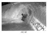
- FIG. 6Ais a right side front perspective view of the injected sheet-flow wave-simulating water ride attraction of FIG. 4A illustrating the formation of a simulated tunnel wave thereon;
- FIG. 6Bis a right side front perspective view of the injected sheet-flow wave-simulating water ride attraction of FIG. 4A illustrating the formation of a simulated tunnel wave thereon and a rider riding inside the tunnel wave and on the injected sheet flow.
- Deep water flowis a flow having sufficient depth such that the pressure disturbance from the rider and his or her vehicle are not significantly influenced by the presence of the bottom over which a body of water flows.
- Sheet flow or shallow flowis a thin flow of water that: (i) has, at a minimum, sufficient depth to allow water skimming maneuvers, and (ii) has a maximum depth that still allows the pressure disturbance from the rider and his or her vehicle to be significantly influenced by the presence of the bottom over which a body of water flows (i.e., ‘a ground effect’).
- a body of wateris a volume of water wherein the flow of water comprising that body is constantly changing, and with a shape thereof at least of a length, breadth and depth sufficient to permit water skimming maneuvers thereon as limited or expanded by the respective type of flow, i.e., deep water or sheet flow.
- Water skimming maneuversare those maneuvers capable of performance on a flowing body of water upon an incline including: riding across the face of the surface of water; riding horizontally or at an angle with the flow of water; riding down a flow of water upon an inclined surface countercurrent to the flow moving up said incline; manipulating the planing body to cut into the surface of water so as to carve an upwardly arcing turn; riding back up along the face of the inclined surface of the body of water and cutting-back so as to return down and across the face of the body of water and the like, e.g., lip bashing, floaters, inverts, aerials, 360's, etc.
- Water skimming maneuverscan be performed with the human body or upon or with the aid of a riding or planing vehicle such as a surfboard, bodyboard, water ski(s), inflatable, mat, innertube, kayak, jet-ski, sail boards, etc.
- a riding or planing vehiclesuch as a surfboard, bodyboard, water ski(s), inflatable, mat, innertube, kayak, jet-ski, sail boards, etc.
- the forward force component required to maintain a riderincluding any skimming device that he may be riding
- a rider's motion upslope(in excess of the kinetic energy added by rider or vehicle) consists of the rider's drag force relative to the upward shooting water flow exceeding the downslope component of gravity.
- Non-equilibrium riding maneuverssuch as turns, cross-slope motion and oscillating between different elevations on the “wave” surface are made possible by the interaction between the respective forces as described above and the use of the rider's kinetic energy.
- the equilibrium zone or equidyne regionis that portion of a inclined riding surface upon which a rider is in equilibrium on an upwardly inclined body of water that flows thereover; consequently, the upslope flow of momentum as communicated to the rider and his or her vehicle through hydrodynamic drag is balanced by the downslope component of gravity associated with the weight of the rider and his or her vehicle.
- the supra-equidyne or superequidyne areais that portion of a riding surface contiguous with but downstream (upslope) of the equilibrium zone wherein the slope of the incline is sufficiently steep to enable a water skimming rider to overcome the drag force associated with the upward water flow and slide downwardly thereupon.
- the sub-equidyne areais that portion of a riding surface contiguous with but upstream (downslope) of the equilibrium zone wherein the slope of the incline is insufficiently steep to enable a water skimming rider to overcome the drag force associated with the upward water flow and stay in equilibrium thereon. Due to fluid drag, a rider will eventually move in the direction of flow back up the incline.
- the Froude number (Fr)is a mathematical expression that describes the ratio of the velocity of the flow to the phase speed of the longest possible waves that can exist in a given depth without being destroyed by breaking.
- the Froude numberequals the flow speed divided by the square root of the product of the acceleration of gravity and the depth of the water.
- the magnitude of the Froude numberis an indicator of the relative dominance between inertial forces (kinetic energy) and gravity forces (potential energy).
- a Froude number much greater than oneindicates that inertial forces (kinetic energy) are dominant over gravity forces (potential energy) while a Froude number much less than one indicates that gravity forces (potential energy) dominate over inertial forces (kinetic energy).
- vis the flow velocity (e.g. in ft/sec or m/sec)
- gis the acceleration due to gravity (e.g. in ft/sec 2 or m/sec 2 )
- dis the depth (e.g. in feet or meters) of the sheet or deep water flow.
- Subcritical flowcan be generally described as a slow/thick water flow. Specifically, subcritical flows have a Froude number (Fr) that is less than 1. If a stationary wave is in a sub-critical flow, then, it will be a non-breaking stationary wave. In formula notation, a flow is subcritical when:
- vis the flow velocity (e.g. in ft/sec or m/sec)
- gis the acceleration due to gravity (e.g. in ft/sec 2 or m/sec 2 )
- dis the depth (e.g. in feet or meters) of the sheeting or deep flowing body of water.
- Critical flowis evidenced by wave breaking.
- Critical flowhas the characteristic physical feature of the hydraulic jump itself Because of the unstable nature of wave breaking, critical flow is difficult to maintain in an absolutely stationary state in a moving stream of water given that the speed of the wave must match the velocity of the stream to remain stationary. This is a delicate balancing act. There is a match for these exact conditions at only one point for one particular flow speed and depth.
- Critical flowshave a Froude number (Fr) equal to one. In formula notation, a flow is critical when:
- vis the flow velocity (e.g. in ft/sec or m/sec)
- gis the acceleration due to gravity (e.g. in ft/sec 2 or m/sec 2 )
- dis the depth (e.g. in feet or meters) of the sheeting or deep flowing body of water.
- Supercritical flowcan be generally described as a thin/fast flow. Specifically, supercritical flows have a Froude number (Fr) greater than 1. No stationary waves are involved. The reason for the lack of waves is that neither breaking nor non-breaking waves can keep up with the flow speed because the maximum possible speed for any wave is the square root of the product of the acceleration of gravity times the water depth. Consequently, any waves which might form are quickly swept downstream. In formula notation, a flow is supercritical when:
- vis the flow velocity (e.g. in ft/sec or m/sec)
- gis the acceleration due to gravity (e.g. in ft/sec 2 or m/sec 2 )
- dis the depth (e.g. in feet or meters) of the sheeting or deep flowing body of water.
- the hydraulic jumpis the point of wave-breaking of the fastest waves that can exist at a given depth of water.
- the hydraulic jumpitself is actually the break point of that wave.
- the breaking phenomenonresults from a local convergence of energy. Any waves that appear upstream of the hydraulic jump in the supercritical area are unable to keep up with the flow, consequently they bleed downstream until they meet the area where the hydraulic jump occurs; now the flow is suddenly thicker and now the waves can suddenly travel faster. Concurrently, the downstream waves that can travel faster move upstream and meet at the hydraulic jump. Thus, the convergence of waves at this flux point leads to wave breaking.
- the hydraulic jumpis an energy transition point where energy of the flow abruptly changes from kinetic to potential. A hydraulic jump occurs when the Froude number (Fr) is 1.
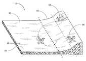
- FIGS. 1 A— 1 Cillustrate a conventional sheet-flow wave-simulating ride attraction 10 .
- the attraction 10includes a ride surface 20 upon which a supercritical flow 39 of sheet-like water 38 is injected by a nozzle or sluice 30 .
- the ride surface 20includes a sloped ride surface 20 ′, including a superequidyne region 58 and an equidyne region 60 , and a subequidyne region 62 which is substantially horizontal.
- the superequidyne region 58transitions (as represented by a dashed line 59 ) to the equidyne region 60 , which in turn transitions (as represented by a dotted line 61 ) to the subequidyne region 62 .
- FIG. 1Balso shows a range of configurations 58 a , 58 b , 58 c for the superequidyne area 58 .
- the elongated nozzle or sluice gate 30is typically provided adjacent the lower end of the ride surface 20 for injecting the sheet-like flow of water 38 onto the ride surface 20 .
- the subequidyne region 62serves as an extended horizontal transition surface between the nozzle 30 and the lower end (transition line) 61 of the sloped ride surface 20 ′.
- the purpose of the extended transition surface 62is to provide an energy-absorbing buffer between the upward sloped ride surface 20 ′ and the nozzle or sluice gate 30 . This buffer prevents riders from possibly colliding with or riding over the sluice gate 30 and/or interfering with the ride operation. Sometimes, this buffer is accomplished by introducing a reverse curve 99 which transitions from the horizontal of the subequidyne area 62 to an upward arc. Nozzle 30 is then positioned at the upstream edge of reverse curve 99 .
- a rider 63is able to ride and perform surfing/skimming maneuvers upon the upward flowing sheet water flow 38 using a specially configured surf-board/flow-board.
- ride board riderscan achieve various conditions of dynamic balance or imbalance between the tangentially acting drag forces and the downward acting gravitational forces. See, for example, U.S. Pat. Nos. 5,236,280 and 5,271,692, each of which is incorporated herein by reference.
- the rider 63is able to control his or her position upon supercritical water flow 39 through a balance of forces, e.g., gravity, drag, hydrodynamic lift, buoyancy, and self-induced kinetic motion.
- rider 63 at position (a)can take advantage of gravitational forces and slide down the upcoming flow by maximizing the hydroplaning characteristics of his ride vehicle and removing drag enhancing hands and feet from the water flow.
- rider 63can reverse this process at position (b) and move back uphill to position (c) with the flow by properly positioning his or her vehicle to reduce planing ability and/or inserting hands and feet into the flow to increase drag.
- Non-equilibrium riding maneuverssuch as turns, cross-slope motion and oscillating between different elevations on the “wave-like” surface are made possible by the interaction between the respective forces as described above and the use of the rider's kinetic energy.
- the extended horizontal riding surface 62extends up to the lower end 61 of the sloped ride surface 20 ′ and provides a safety buffer between the rider 63 and the nozzle/sluice 30 .
- the horizontal surface 62can vary in length, but is typically three times the highest elevation of ride surface 20 or 20 ′.
- a reverse curve 99FIG. 1B
- the length of the horizontal surface (subequidyne area) 62can be reduced, however, reverse curve 99 still requires increased space, cost and its added height blocks the visibility of spectators who are situated in front of nozzle/sluice 30 .
- the length of the horizontal surface 62is designed to be long enough to cause the rider 63 riding down the inclined surface 20 ′ due to gravity, to be slowed down and then propelled back up the incline by the drag force of the supercritical flow 39 of sheet-like water 38 . If the horizontal surface 62 were too short in length, the rider could potentially come down the incline 20 and conceivably, overrun the nozzle 30 . Thus, the horizontal transition surface 62 typically has a length sufficient to provide enough momentum transfer to push the rider back up the incline 20 ′ before he or she reaches the nozzle/sluice 30 .
- FIGS. 2 A— 2 Billustrate another conventional injected sheet-flow ride attraction 10 ′ specifically for installation adjacent a municipal pool or other associated body of water 21 .
- the nozzle 30is positioned at a level substantially equal to or lower than the elevation of the water surface in the pool area 21 .
- a supercritical flow of wateris injected onto the ride surface 20 through the nozzle 30 pointed in the direction of flow.
- the nozzle 30is slightly submerged within the pool 21 so that the nozzle 30 does not obstruct riders flowing over the nozzle area.
- ridersmay ride over the nozzle 30 and be propelled up the inclined surface 20 ′ directly from the pool area 21 , which advantageously increases user capacity and throughput
- the outlet nozzle 30is located substantially in the center of the pool area 21 and directs water in a unidirectional flow up the inclined surface 20 ′ and around the butterfly return 32 .
- a circulation pump 44is situated at the deep end of the pool 21 .
- FIG. 2Bshows how the incline surface 20 is typically positioned within an existing swimming pool, with the entry ramp 22 and slide 40 at one end of the pool. Also shown are a flow transition area 42 (FIG. 2A) and a sump area 28 (FIG. 2 B).
- FIG. 2Balso shows an extended horizontal transition surface 46 which typically extends at least about 5 meters or about 15 feet in length.
- the horizontal surface 46is designed to be long enough to cause the rider riding down the inclined surface 20 ′ due to gravity, to be propelled back up the incline 20 ′ by the force of the supercritical flow. If the horizontal surface area 46 were too short in length, the rider would come down the incline 20 ′, and conceivably, overrun the nozzle 30 . Thus, the horizontal surface 46 is sufficiently long to provide enough momentum transfer to push the rider back up the incline 20 ′ before he or she reaches the nozzle outlet area 30 .
- FIGS. 3 A— 3 Dillustrate one preferred embodiment of a novel injection nozzle assembly 188 for use in conjunction with a water ride attraction and having features in accordance with one preferred embodiment of the present invention.
- the nozzle/sluice assembly 188generally comprises a nozzle or sluice gate 130 and a slide-over cover 150 which enables riders to safely slide over the nozzle 130 without risk of injury or interference with ride operation.
- a docking or launch pad 190is provided in communication with the padded cover 150 and above the nozzle 130 .
- the nozzle/sluice assembly 188 of the present inventionwhen incorporated into a water ride attraction accommodates the omission and/or shortening of the extended transition area typically found in conventional water ride attractions. Desirably, this provides greater flexibility in increasing the available ride area (i.e., the sloped ride surface) for maximum rider enjoyment and also reduces the overall size of the ride attraction, thus facilitating the creation of larger and more exciting waves in tight spaces, such as in hotels, restaurants and the like.
- the nozzle assembly 188when used in conjunction with the water ride attraction 10 (FIGS. 1 A— 1 C) will allow omission and/or considerable shortening of the extended transition area 62 .
- the extended transition area 46can be desirably omitted and/or considerably shortened.
- the sluice-gate assembly 188 of the present inventioncan be efficaciously used in conjunction with a wide variety of water ride attractions, as required or desired, giving due consideration to the goals of providing rider safety, ride attraction compactness, and/or of achieving one or more of the benefits and advantages as taught or suggested herein.
- These water ride attractionsinclude without limitation sheet flow simulated wave water ride attractions, deep flow simulated wave water ride attractions, among others.
- Water(or other liquid) is provided to the nozzle 130 (FIGS. 3 A— 3 D) via a pump 144 (FIG. 3A) and exits the nozzle aperture 192 (see FIGS. 3A and 3B) as supercritical fluid flow 138 (see FIG. 3A) onto a ride surface 120 .
- the nozzle 130is positioned such that the nozzle aperture or opening 192 is located at or just above the level of the end of the ride surface 120 .
- the pump 144is preferably positioned below the level of the ride surface 120 , though it can be located elsewhere as mandated by site specific conditions or as desired.
- the nozzle or sluice gate 130preferably has a generally narrowing or decreasing internal cross-section area in the direction moving away from the pump 144 and towards the nozzle outlet 192 .
- the sluice gate or nozzle 130has a generally beak like shape to minimize the overall height of the sluice gate's fixed decking 190 above the emitted flow 138 .
- the nozzle or sluice gate 130may be efficaciously shaped and/or configured in a wide variety of manners, as required or desired, giving due consideration to the goals of achieving one or more of the benefits and advantages as taught or suggested herein.
- the sluice gate 130is preferably made of either steel, fiberglass, reinforced concrete or other structurally suitable material that can withstand water pressures in the range from about 55 kilopascals to about 310 kilopascals (about 8 psi to about 45 psi or about 0.5 bar to about 3 bar).
- the sluice gate 130can comprise other metals, alloys, ceramics, plastics, composite materials and the like with efficacy, as required or desired, giving due consideration to the goals of providing a suitably strong sluice gate 130 , and/or of achieving one or more of the benefits and advantages as taught or suggested herein.
- the sluice gate 130is preferably made of either steel, fiberglass, reinforced concrete or other structurally suitable material that can withstand water pressures in the range from about 14 kilopascals to about 310 kilopascals (about 2 psi to about 45 psi or about 0.1 bar to about 3 bar).
- the sluice gate 130can comprise other metals, alloys, ceramics, plastics, composite materials and the like with efficacy, as required or desired, giving due consideration to the goals of providing a suitably strong sluice gate 130 , and/or of achieving one or more of the benefits and advantages as taught or suggested herein.
- the vertical opening of the sluice aperture 192is preferably about 8 cm (3 inches). In another preferred sheet flow embodiment, the vertical opening of the sluice aperture 192 is in the range from about 4 cm to about 30 cm (about 1.5 inches to about 12 inches). In other preferred embodiments, the sluice gate 130 can be efficaciously sized and/or dimensioned in alternate manners, as required or desired, giving due consideration to the goals of providing a suitable sheet flow, and/or of achieving one or more of the benefits and advantages as taught or suggested herein.
- the vertical opening of the sluice aperture 192is preferably about 61 cm (24 inches). In another preferred sheet flow embodiment, the vertical opening of the sluice aperture 192 is in the range from about 30 cm to about 1.8 m (about 12 inches to about 6 feet). In other preferred embodiments, the sluice gate 130 can be efficaciously sized and/or dimensioned in alternate manners, as required or desired, giving due consideration to the goals of providing a suitable deep water flow, and/or of achieving one or more of the benefits and advantages as taught or suggested herein.
- the slide-over sluice gate cover 150is preferably configured to permit users of an injected sheet- or deep-flow water ride attraction to safely slide over the padded aperture 192 and onto the padded fixed decking 190 .
- the sluice cover 150preferably comprises a contoured flexible pad which covers and extends over the top surface of the sluice gate 130 .
- the sluice cover 150has a flexible and removable tongue-like pad that is affixed above the sluice aperture 192 and in the downstream direction extends over the water that jets from the sluice aperture 192 , and in the upstream direction abuts to the padded fixed decking 190 upon which the user will safely beach.
- the tongue-like pad 150preferably includes a tongue portion 160 that in the downstream direction extends over the jetting water 138 , and a rear generally flat portion 170 that in the upstream direction abuts to the padded fixed decking 190 .
- the tongue-like pad 150also desirably provides a short transition surface over the top of which a rider can slide without injury.
- the tongue-like pad 150(or tongue 160 ) is preferably urged downward to squeeze against the flow 138 and to seal or cover the nozzle area off from possible injurious contact from a rider.
- the pad 150 (or tongue 160 )is spring-loaded in a downward direction to keep a light tension against the jetted water 138 .
- thisreduces or minimizes the possibility of a rider catching a finger underneath the pad 150 (or tongue 160 ) when sliding up and over the pad 150 (or tongue 160 ) and sluice gate 130 .
- other suitable resilient meanscan be efficaciously used to bias or urge the tongue-like pad 150 (or tongue 160 ) in a downward direction towards the ride surface 120 .
- the sluice cover (tongue-like pad) 150can be removably mechanically connected to the nozzle or jet 130 in a wide variety of manners, preferably utilizing screws or the like.
- this removable featureallows for easy replacement of the sluice cover 150 , as needed or desired.
- alternate suitable securing meansmay be efficaciously used to removably attach the sluice cover 150 , as required or desired, giving due consideration to the goals of providing reliable, removable and safe attachment, and/or of achieving one or more of the benefits and advantages as taught or suggested herein.
- the sluice cover or pad 130preferably ranges in thickness from about 1.6 mm ( ⁇ fraction (1/16) ⁇ th inch) thick at its furthest downstream point to approximately 2.54 cm (1 inch) thick where it abuts to the fixed decking 190 .
- the sluice cover 130can be efficaciously sized and/or dimensioned in alternate manners, as required or desired, giving due consideration to the goals of providing a suitably resilient and strong nozzle cover, and/or of achieving one or more of the benefits and advantages as taught or suggested herein.
- the sluice cover or pad 130is preferably made out of any suitable soft flexible material that will avoid injury upon impact, yet rigid enough to hold its shape under prolonged use.
- Suitable pad materialsinclude a 32 kg/m 3 (2 lb/ft 3 ) density closed cell polyurethane foam core that is coated with a tough but resilient rubber or plastic, e.g., polyurethane paint or vinyl laminate.
- the pad 130 or pad materialcan be reinforced internally or externally, if needed. In other preferred embodiments, alternate materials may be efficaciously used, as required or desired, giving due consideration to the goals of providing a suitably soft, flexible yet rigid pad, and/or of achieving one or more of the benefits and advantages as taught or suggested herein.
- the padded fixed decking 190can be provided in combination with the nozzle assembly 188 or it can comprise part of the nozzle assembly 188 .
- the decking 190extends away from the direction of water flow 138 and is located above the level of the nozzle 130 .
- the decking or platform 190is generally flat and rectangular, and abuts against or is in mechanical communication with the upstream end of the sluice cover 150 to provide a generally smooth transition between the respective upper surfaces of the cover 130 and decking 190 .
- the decking 190rests at a forward end 194 on the top of the outer surface of the nozzle 130 and at a rear end 196 on top of a support structure or supports 198 (see FIG. 3 A).
- a variety of suitable means, such as screws or the like,may be used to secure and fasten the decking 190 in place.
- the decking 190preferably has a thickness of about 2.5 cm (1 inch).
- the length of the decking 190is such that the distance between the decking rear end 196 and the nozzle aperture 192 is about 1.63 m (64 inches).
- the width of the deckingis about 2.4 m (8 feet).
- the decking 190is positioned such that the its upper surface is about 26.4 cm (10.4 inches) above the upstream end of the ride surface 120 .
- the decking 190is also positioned such that the distance labeled L D in FIG. 3A is about 35.6 cm (14 inches).
- the padded fixed decking 190can be efficaciously sized, configured and/or positioned in alternate manners, as required or desired, giving due consideration to the goals of providing a suitable launch/exit pad, ride surface, and/or of achieving one or more of the benefits and advantages as taught or suggested herein.
- the decking 190is fabricated from a foam material covered with a plastic to provide additional protection for the riders.
- alternate materialsmay be efficaciously used, as required or desired, giving due consideration to the goals of providing a suitably strong yet safe pad, and/or of achieving one or more of the benefits and advantages as taught or suggested herein.
- the padded decking 190serves several functions.
- the decking 190can be used as a launch pad by the rider of the water ride attraction. The rider can then exit the attraction by sliding over the nozzle cover 130 and onto the decking 190 , and hence can gracefully or elegantly exit off of the ride surface 120 rather than exiting by being swept, sometimes ungracefully, onto a designated beach area on which a water wave breaks.
- the platform 190 and nozzle cover 130also provide a new dimension in performing water skimming maneuvers and tricks in that a rider may use the wetted slick and/or slippery platform 190 and/or nozzle cover 130 as part of the ride surface.
- the ridercan skim over the sheet or deep water flow 138 and onto and over the surface of the cover 130 and platform 190 in an alternating or zig-zag pattern or can perform skateboard-like tricks. This adds to the excitement of the water ride attraction and permits a greater range of selection of water skimming or surfing maneuvers.
- a plurality of nozzle or sluice-assemblies 188 of the present inventioncan be employed in a particular water ride attraction, as needed or desired. These nozzle assemblies 188 can be used in conjunction with a sheet or deep water flow ride attraction.
- the ride surface of the attractioncan be a containerless incline or it may be bounded by one or more side and/or end walls.
- a deep water flow ride attractioncomprises one or more of the nozzle assemblies 188 and a ride surface installed in a container.
- nozzle assembly 188allows for omission or shortening of the extended transition surface, and hence permits construction of compact water ride attractions which can also entertain larger ride surfaces. This compactness can also facilitate in providing water ride attractions that are transportable between different sites.
- this mobilityprovides enhanced versatility and convenience and can lower manufacturing and operational costs.
- FIGS. 4 A— 4 D and 5 A— 5 Cillustrate preferred embodiments of a mobile injected sheet-flow ride attraction 100 in which the extended transition surface has been omitted or significantly shortened in accordance with the teachings and advantages of the present invention.
- the ride attraction 100comprises a plurality of nozzle assemblies 188 , as illustrated in FIGS. 3 A— 3 D, with each including a slide-over sluice cover 150 and a padded fixed decking 190 .
- FIG. 6Ais a perspective view of the injected sheet-flow wave-simulating water ride attraction 100 and illustrates the formation of a simulated tunnel wave thereon approximately three meters high.
- FIG. 6Bis a perspective view of the injected sheet-flow wave-simulating water ride attraction 100 illustrating a rider riding inside the simulated tunnel wave and upon the injected sheet water flow.
- the compactness and/or modularity of the water ride attraction 100advantageously allow it to be transported or shipped between different sites via truck, train or other vehicle.
- the prefabricated components of the ride attraction 100can be quickly assembled on-site without the need for a time-consuming long, drawn out construction process. This provides enhanced versatility, convenience and also keeps costs low.
- the ride surface 120comprises a sloped portion 120 ′ and a generally flat or horizontal portion 162 with the sloped ride surface 120 ′ nearly adjacent or close to the sheet-flow injection nozzles/sluices 130 .
- thisincreases the available ride area for maximum rider enjoyment and also reduces the overall size of the ride attraction, thus facilitating the creation of larger and more exciting waves in tight spaces, such as in hotels and restaurants.
- the water ride attraction 100comprises a plurality of shippable modules, units or containers 211 , 212 , 213 , 214 , 215 , 216 , 217 and 218 .
- these containerscomprise standard shipping containers/crates.
- the independent modules 211 , 212 , 213 , 214 , 215 , 216 , 217 and 218 along with other ride attraction componentsare transported to the designated site and preferably assembled on-site to form the water ride attraction 100 .
- a suitable suspension 250(FIG. 5A) is provided to keep the ride attraction or machine 100 level.
- Selected external surfaces of the containers 211 , 212 , 213 , 214 , 215 , 216 , 217 and 218can be painted to provide an aesthetic appearance, as needed or desired.
- a similar modular structurecan also be efficaciously utilized to provide a mobile deep water flow ride attraction.
- the modules 211 , 212 , 213 , 214 , 215 , 216 , 217 and 218are preferably sized to facilitate truck or train transport such as in a standard shipping crate.
- the modules 211 , 212 , 213 , 214 , 215 , 216 , 217 and 218include standard IICL 5 corner fittings/castings 262 (FIG. 4B) which allow the modules to be brought together and removably connected using standard shipping container/crate bridge fittings, as is known in the art.
- the modulescan be attached using other fastening devices and mechanisms, such as nut-bolt combinations, screws, locks, clamps and the like, with efficacy, as required or desired, giving due consideration to the goals of securely and removably attaching the modules, and/or of achieving one or more of the benefits and advantages as taught or suggested herein.
- fastening devices and mechanismssuch as nut-bolt combinations, screws, locks, clamps and the like
- Each one of the modules 213 , 214 , 215 , 216houses a circulation pump 144 which is in fluid communication with a respective flow forming nozzle 130 which emits a supercritical water flow 138 onto the contoured ride surface 120 .
- a tongue-like pad 150(FIGS. 3 A— 3 D) and a padded fixed decking 190 (FIGS. 3 A— 3 D) is provided with each nozzle 130 , as discussed above.
- a single tongue-like pad/cover 150 and/or padded fixed decking 190is utilized with the plurality of nozzles 130 and attached after assembly of the modules 213 , 214 , 215 , 216 .
- the four pumps 144move water in the four containers 213 , 214 , 215 , 216 beneath the wave and the ride surface 120 , and provide it to respective nozzles or sluices 130 .
- Ride surfaces 213 a , 213 bare associated with the module or container 213 .
- the ride surfaces 213 a , 213 bcomprise a portion of the contoured ride surface 120 .
- ride surface 213 bis removed or detached from the module 213 during transport, to facilitate transportation of the module 213 , ride surface 213 b and/or other components of the water ride attraction 100 .
- the ride surface 213 bis reattached to the module 213 .
- Ride surfaces 214 a , 214 bare associated with the module or container 214 .
- the ride surfaces 214 a , 214 bcomprise a portion of the contoured ride surface 120 .
- ride surface 214 bis removed or detached from the module 214 during transport, to facilitate transportation of the module 214 , ride surface 214 b and/or other components of the water ride attraction 100 .
- the ride surface 214 bis reattached to the module 214 .
- the ride surface 214 bcan also comprise two removably attachable surfaces, as needed or desired.
- Ride surfaces 215 a , 215 bare associated with the module or container 215 .
- the ride surfaces 215 a , 215 bcomprise a portion of the contoured ride surface 120 .
- ride surface 215 bis removed or detached from the module 215 during transport, to facilitate transportation of the module 215 , ride surface 215 b and/or other components of the water ride attraction 100 .
- the ride surface 215 bis reattached to the module 215 .
- Ride surfaces 216 a , 216 bare associated with the module or container 216 .
- the ride surfaces 216 a , 216 bcomprise a portion of the contoured ride surface 120 .
- ride surface 216 bis removed or detached from the module 216 during transport, to facilitate transportation of the module 216 , ride surface 216 b and/or other components of the water ride attraction 100 .
- the ride surface 216 bis reattached to the module 216 .
- a flow fence or side wall 222is associated with the module or container 216 .
- the flow control fence 222serves to avoid spillage and wastage of the water flowing on the ride surface 120 and can also function as a safety fence.
- flow fence 222is removed or detached from the module 216 during transport, to facilitate transportation of the module 216 , flow fence 222 and/or other components of the water ride attraction 100 .
- the flow fence 222is reattached to the module 216 .
- the contoured surface 120is configured with shoulders 230 and curls 232 (labeled in FIG. 4D) to create waves of a preselected or predetermined configuration.
- the ramp or curls 232form a lip that causes the breaking and/or tunneling wave effect.
- the contoured surface 120can be configured and/or shaped in alternate manners with efficacy, as required or desired, giving due consideration to the goals of providing a preselected or predetermined wave and/or flow structure, and/or of achieving one or more of the benefits and advantages as taught or suggested herein.
- the top of the splash down module 211preferably includes a mat over porous grating or drain area 224 .
- Surfaces or walls 211 a , 211 bare associated with the module or container 211 .
- ride surface 211 bis removed or detached from the module 211 during transport, to facilitate transportation of the module 211 , ride surface 211 b and/or other components of the water ride attraction 100 .
- the ride surface 211 bis reattached to the module 211 .
- the grates 224 , 226can hold riders coming off a wave and in combination with one or more of the surfaces/walls 211 a , 211 b , 212 a , 212 b form a beaching area 228 .
- One or more of the surfaces/walls 211 a , 211 b , 212 a , 212 bcan also form a flow control and/or safety fence.
- the grates or drains 224 , 226allow water 138 a (FIG. 4D) to flow down into respective containers 211 , 212 .
- the drained water from container 211then flows into container 212 which directs it along with its own collected drained water to the catch pool or container 217 .
- the top of the upper splash down module 217preferably includes a mat over porous grating or drain area 234 .
- One or more posts 236 and a tensioned fabric splash guard and/or safety fence 238are associated with the top of module or container 217 .
- posts 236 and/or splash guard 238are removed or detached from the module 217 during transport, to facilitate transportation of the module 217 , posts 236 , splash guard 238 and/or other components of the water ride attraction 100 .
- the posts 236 and/or splash guard 238are reattached to the module 217 .
- a drain pipe 260 or the likeis also connected to the container 217 for draining water into a waste position, as needed or required.
- the grate 234can hold riders exiting the ride attraction 100 while keeping the riders distanced from the pumps 144 and also forms a beaching area 240 .
- the grate or drain 234allows water or water flow 138 b (FIGS. 4D, 5 A and 5 B) overflowing from the ride to flow down into the container or catch pool 217 .
- This water 138 b along with drained water from the containers 211 , 212is directed by the catch pool 217 through openings 242 (FIG. 5B) back towards the pumps 144 as water or water flow 138 c (FIGS. 5 B and 5 C).
- the water 138 centers chambers 244 , which have a reducing area in the downstream direction, through honey-combed shaped openings 246 , thereby increasing the pressure as the water 138 d enters the pumps 144 .
- the pumps 144push the water through respective reducers 248 which further increases the pressure and into respective nozzles 130 .
- the water from the pumps 144is forced upward and over backwards, turning the water upwardly about 180°.
- the nozzles 130shoot or jet the supercritical water flow 138 onto the foam ride surface 120 having contoured and shaped surfaces and/or ramps to form a wave of predetermined or preselected configuration.
- the module 218preferably comprises a control and filtration closed top container which is responsible for controlling and monitoring the operation of the water ride attraction 100 .
- the module 218is connected to power lines 252 from one or more generators.
- the module 218houses a plurality of control panels 254 and a filtration system 256 .
- Various cabling and/or lines 258are associated with module 218 such as power cables, signal cables, source and filtered water line(s), fill level control, system drain line and the like.
- Each of the nozzles 130 and/or pumps 144preferably provides a water flow rate of about 1700 liters/sec (27,000 gallons/minute or GPM) for a total flow rate of about 6800 liters/sec (108,000 GPM) onto the ride surface 120 to form a preferred wave structure.
- a total flow rateabout two-third or 1130 liters/sec (72,000 GPM) exits the ride surface as water 138 a via the grates 224 , 226 and about one-third or 570 liters/sec (36,000 GPM) overflows as water 138 b into the grate 234 .
- the drained wateris then recirculated from the catch pool 217 to the pumps 144 .
- different flow rates and fewer or more nozzles, pumps and/or modulescan be efficaciously used, as required or desired, giving due consideration to the goals of providing a predetermined or preselected wave form and/or flow structure, and/or of achieving one or more of the benefits and advantages as taught or suggested herein.
- the ride surfaces 213 a , 214 a , 215 a , 216 a , 215 b and 216 bhave top surface areas of about 22.9 m 2 (247 sq ft), 19.5 m 2 (210 sq ft), 14.3 m 2 (154 sq ft), 10.4 m 2 (112 sq ft), 12.6 m 2 (136 sq ft) and 13.4 m 2 (144 sq ft), respectively.
- the ride surfaces 213 b and 214 bhave top (including back) surface areas of about 9.6 m 2 (103 sq ft) and 12.4 m 2 (133 sq ft), respectively.
- the surfaces 211 a , 211 b and 212 ahave top surface areas of about 6.8 m 2 (73 sq ft), 3.3 m 2 (35 sq ft) and 18.7 m 2 (201 sq ft), respectively.
- the surface 212 bhas a top (including back) surface area of about 8.1 m 2 (87 sq ft).
- the surfaces 211 a , 211 b , 212 a , 212 b , 213 a , 213 b , 214 a , 214 b , 215 a , 215 b , 216 a , 216 bcan be efficaciously sized and configured in alternate manners, as required or desired, giving due consideration to the goals of achieving one or more of the benefits and advantages as taught or suggested herein.
- the dimensions B 1 , B 2 , B 3 , B 4 , B 5 and B 6are about 3.048 m (10 ft), 2.438 m (8 ft), 14.63 m (48 ft), 2.591 m (8.5 ft), 4.249 m (13.94 ft) and 2.355 m (7.729 ft), respectively.
- the ride attraction 100can be sized and/or configured in other manners with efficacy, as required or desired, giving due consideration to the goals of providing a compact and/or mobile ride attraction having modules and components that are transportable between sites, and/or of achieving one or more of the benefits and advantages as taught or suggested herein.
- the dimensions C 1 , C 2 , C 3 , C 4 , C 5 , C 6 and C 7are about 17.069 m (56 ft), 0.457 m (1.5 ft), 1.524 m (5 ft), 2.591 m (8.5 ft), 3.023 m (9.917 ft), 3.962 m (13 ft) and 5.41 m (17.75 ft), respectively.
- the ride attraction 100can be sized and/or configured in other manners with efficacy, as required or desired, giving due consideration to the goals of providing a compact and/or mobile ride attraction having modules and components that are transportable between sites, and/or of achieving one or more of the benefits and advantages as taught or suggested herein.
- the dimensions D 1 , D 2 , D 3 , D 4 , D 5 and D 6are about 12.192 m (40 ft), 9.144 m (30 ft), 2.438 m (8 ft), 14.63 m (48 ft), 17.069 m (56 ft) and 12.192 m (40 ft), respectively.
- the ride attraction 100can be sized and/or configured in other manners with efficacy, as required or desired, giving due consideration to the goals of providing a compact and/or mobile ride attraction having modules and components that are transportable between sites, and/or of achieving one or more of the benefits and advantages as taught or suggested herein.
- the major footprint of the water ride attraction 100is about 14.63 m (48 ft) ⁇ 17.069 m (56 ft).
- the modules or containers 211 , 212 , 213 , 214 , 215 , 216 , 217 , 218have a width of about 2.438 m (8 ft), a length of about 12.192 m (40 ft) and a height of about 2.591 m (8.5 ft).
- this size configurationpermits the modules or containers 211 , 212 , 213 , 214 , 215 , 216 , 217 , 218 to be shipped or transported using suitable trucks, trains or other vehicles.
- the ride attraction 100can be sized and/or configured in other manners with efficacy, as required or desired, giving due consideration to the goals of providing a compact and/or mobile ride attraction having modules and components that are transportable between sites, and/or of achieving one or more of the benefits and advantages as taught or suggested herein.
Landscapes
- Engineering & Computer Science (AREA)
- Architecture (AREA)
- Civil Engineering (AREA)
- Structural Engineering (AREA)
- Nozzles (AREA)
- Road Paving Structures (AREA)
- Barrages (AREA)
- Sliding Valves (AREA)
- Catching Or Destruction (AREA)
Abstract
Description

Claims (57)
Priority Applications (1)
| Application Number | Priority Date | Filing Date | Title |
|---|---|---|---|
| US09/630,878US6491589B1 (en) | 1999-08-02 | 2000-08-02 | Mobile water ride having sluice slide-over cover |
Applications Claiming Priority (2)
| Application Number | Priority Date | Filing Date | Title |
|---|---|---|---|
| US14675199P | 1999-08-02 | 1999-08-02 | |
| US09/630,878US6491589B1 (en) | 1999-08-02 | 2000-08-02 | Mobile water ride having sluice slide-over cover |
Publications (1)
| Publication Number | Publication Date |
|---|---|
| US6491589B1true US6491589B1 (en) | 2002-12-10 |
Family
ID=22518846
Family Applications (1)
| Application Number | Title | Priority Date | Filing Date |
|---|---|---|---|
| US09/630,878Expired - LifetimeUS6491589B1 (en) | 1999-08-02 | 2000-08-02 | Mobile water ride having sluice slide-over cover |
Country Status (8)
| Country | Link |
|---|---|
| US (1) | US6491589B1 (en) |
| EP (1) | EP1210155B9 (en) |
| CN (1) | CN1162199C (en) |
| AT (1) | ATE312253T1 (en) |
| AU (1) | AU774900B2 (en) |
| DE (1) | DE60027172T2 (en) |
| WO (1) | WO2001008770A1 (en) |
| ZA (1) | ZA200201727B (en) |
Cited By (49)
| Publication number | Priority date | Publication date | Assignee | Title |
|---|---|---|---|---|
| US6629803B1 (en)* | 2002-03-19 | 2003-10-07 | Mcfarland Bruce C. | Wave forming apparatus and method |
| US20030236048A1 (en)* | 2002-02-09 | 2003-12-25 | Lee Robert Stephen | Beach wave playset |
| US6726403B1 (en)* | 1999-08-02 | 2004-04-27 | Stephen Con Kriticos | Device and method for forming waves |
| US20050215139A1 (en)* | 2004-03-10 | 2005-09-29 | Starr Jason M | Method and apparatus for surf skiing |
| US20060026746A1 (en)* | 2002-03-19 | 2006-02-09 | Mcfarland Bruce C | Wave forming apparatus and method |
| US20070051038A1 (en)* | 2005-04-20 | 2007-03-08 | Henry Jeffery W | Tree with covering apparatus |
| US20070087849A1 (en)* | 2005-09-02 | 2007-04-19 | Henry Jeffery W | Amusement water rides involving exercise circuits |
| US20070087854A1 (en)* | 2005-09-02 | 2007-04-19 | Henry Jeffery W | Methods and systems for positionable screen for self-contained floating marine parks |
| US20080089744A1 (en)* | 2006-10-17 | 2008-04-17 | American Wave Machines, Inc. | Barreling wave generating apparatus and method |
| US7401786B2 (en)* | 2001-01-24 | 2008-07-22 | Light Wave, Ltd. | Surf toy action figure and simulated surfing game |
| WO2009064447A1 (en)* | 2007-11-13 | 2009-05-22 | Lochtefeld Thomas J | Method and apparatus for storing and transporting portable stationary sheet flow water rides |
| US20090169305A1 (en)* | 2007-11-13 | 2009-07-02 | Lochtefeld Thomas J | Method and apparatus for varying water flow for stationary sheet flow water rides |
| US7597630B2 (en) | 2004-11-24 | 2009-10-06 | Water Ride Concepts, Inc. | Water amusement park conveyors |
| US7727077B2 (en) | 2005-08-03 | 2010-06-01 | Water Ride Concepts, Inc. | Water amusement park water channel flow system |
| US7740542B2 (en) | 2000-09-11 | 2010-06-22 | Water Ride Concepts, Inc. | Water amusement method |
| US7762899B2 (en) | 2005-08-30 | 2010-07-27 | Water Ride Concepts, Inc. | Water amusement park conveyor support elements |
| US7762900B2 (en) | 2006-03-14 | 2010-07-27 | Water Ride Concepts, Inc. | Method and system of positionable covers for water amusement parks |
| US7775894B2 (en) | 2003-10-24 | 2010-08-17 | Water Ride Concepts, Inc. | Method and system of participant identifiers for water amusement parks |
| US7775895B2 (en) | 2005-08-03 | 2010-08-17 | Water Ride Concepts, Inc. | Water amusement park water channel and adjustable flow controller |
| US7789804B1 (en)* | 1999-06-24 | 2010-09-07 | Worldslide, L.L.C. | Sliding exercise apparatus and recreational device |
| US7815514B2 (en) | 2005-08-30 | 2010-10-19 | Water Ride Concepts, Inc. | Water amusement park conveyor barriers |
| US7857704B2 (en) | 2005-09-15 | 2010-12-28 | Water Ride Concepts, Inc. | Amusement water rides involving games of chance |
| US20110171618A1 (en)* | 2008-08-08 | 2011-07-14 | Madea Concept Sas | System for Artificially Creating the Practice of a Water Board Sport |
| US8079916B2 (en) | 2008-12-18 | 2011-12-20 | Water Ride Concepts, Inc. | Themed amusement river ride system |
| US8096892B2 (en) | 2002-03-25 | 2012-01-17 | Water Ride Concepts, Inc. | Control system for water amusement devices |
| US8282497B2 (en) | 2005-08-30 | 2012-10-09 | Water Ride Concepts, Inc. | Modular water amusement park conveyors |
| US20140106890A1 (en)* | 2012-10-13 | 2014-04-17 | Pacific Surf Designs, Inc. | Water attractions involving a flowing body of water |
| US9079111B2 (en) | 2009-11-13 | 2015-07-14 | Proslide Technology Inc. | Water slide |
| US20150209807A1 (en)* | 2012-10-24 | 2015-07-30 | Pacific Surf Designs, Inc. | Nozzle shapes and configurations for water attractions involving a flowing body of water |
| US9463390B2 (en) | 2013-10-30 | 2016-10-11 | FlowriderSurf, Ltd. | Inflatable surfing apparatus and method |
| US9550127B2 (en) | 2013-03-21 | 2017-01-24 | Thomas J. Lochtefeld | Padded grate drainage system for water rides |
| US20170292547A1 (en)* | 2014-07-03 | 2017-10-12 | The Boeing Company | Assemblies including shape memory alloy fittings and composite structural members |
| CN107930138A (en)* | 2017-11-21 | 2018-04-20 | 华强方特(芜湖)文化科技有限公司 | A kind of water wave blocks safeguard |
| US10119285B2 (en) | 2017-01-20 | 2018-11-06 | The Wave Pool Company, LLC | Systems and methods for generating waves |
| US10158271B2 (en)* | 2014-08-08 | 2018-12-18 | Challa Balaiah MALLIKARJUNA | System for generating hydrokinetic power from a subcritical channel |
| US10195535B2 (en) | 2015-11-12 | 2019-02-05 | Whitewater West Industries Ltd. | Transportable inflatable surfing apparatus and method |
| US20190169867A1 (en)* | 2018-01-04 | 2019-06-06 | Thursday Pools | Beach entry fiberglass pool system |
| US10335694B2 (en) | 2015-11-12 | 2019-07-02 | Whitewater West Industries Ltd. | Method and apparatus for fastening of inflatable ride surfaces |
| USD855136S1 (en) | 2017-06-08 | 2019-07-30 | Whitewater West Industries Ltd. | Looping ride element |
| US10376799B2 (en) | 2015-11-13 | 2019-08-13 | Whitewater West Industries Ltd. | Inflatable surfing apparatus and method of providing reduced fluid turbulence |
| WO2020152386A1 (en)* | 2019-01-25 | 2020-07-30 | Fun & Waves, S.L. | Transportable surfing-simulating machine |
| WO2021026279A1 (en) | 2019-08-05 | 2021-02-11 | Brad Koide | Water attraction ride surface and methods |
| US11090573B2 (en) | 2013-10-30 | 2021-08-17 | Whitewater West Industries, Ltd. | Inflatable surfing apparatus and method |
| US11260309B2 (en) | 2014-06-13 | 2022-03-01 | Proslide Technology Inc. | Water ride |
| US11273383B2 (en) | 2017-11-10 | 2022-03-15 | Whitewater West Industries Ltd. | Water ride attraction incorporating a standing wave |
| US11534672B2 (en) | 2016-11-08 | 2022-12-27 | Ka'ana Wave Company Inc. | Wave producing method and apparatus |
| US12109471B2 (en) | 2020-10-06 | 2024-10-08 | Sunfun1, Llc | Convertible recreational floatation board game device |
| US12318705B1 (en)* | 2025-01-28 | 2025-06-03 | John R. Van Rosendale | System for modeling animated artificial water surfaces |
| US12352068B2 (en) | 2017-08-30 | 2025-07-08 | Kelly Slater Wave Company, Llc | Wave pool and wave generator for bi-directional and dynamically-shaped surfing waves |
Families Citing this family (10)
| Publication number | Priority date | Publication date | Assignee | Title |
|---|---|---|---|---|
| FR2851930A1 (en)* | 2003-03-07 | 2004-09-10 | Jean Louis Antoine Saquy | Water skier e.g. children, initiating, coaching and perfecting device, has mast sealed on pool side and with fastened cord and handle, and turbines propelling water to offer lift on water, where propelled water returns to pool by conduit |
| PL1988235T3 (en)* | 2007-04-30 | 2011-11-30 | Inotec | Water ride attraction arrangement |
| RU2451533C1 (en)* | 2011-03-22 | 2012-05-27 | Анатолий Павлович Ефимочкин | System for training skiers and method of its realisation |
| PT2707558T (en)* | 2011-05-04 | 2017-12-29 | Stagger Reef Pte Ltd | Wave pool and method for producing periodic waves in such a wave pool |
| ES2436512B1 (en)* | 2012-06-27 | 2014-10-08 | Alfredo OSORIO VARELA | Artificial installation for water surfing |
| CN108407990A (en)* | 2017-02-09 | 2018-08-17 | 北京飞波滑板冲浪模拟器有限公司 | A kind of water outlet water spray damper equipment |
| CN107961542B (en)* | 2017-11-21 | 2023-09-08 | 华强方特(芜湖)文化科技有限公司 | Automatic water wave cutting system with double-layer blocking mechanism |
| CN108118920A (en)* | 2018-01-23 | 2018-06-05 | 深圳市蔚蓝滨海产业投资有限公司 | Inflatable artificial waves's device |
| WO2022183273A1 (en)* | 2021-03-03 | 2022-09-09 | Whitewater West Industries, Ltd. | Wave system and method |
| CN117580621B (en)* | 2021-07-05 | 2024-11-05 | 蒂洛·特雷夫茨 | Pump unit with radial pump and diffuser for a mobile surfing installation |
Citations (31)
| Publication number | Priority date | Publication date | Assignee | Title |
|---|---|---|---|---|
| US1655498A (en) | 1927-04-08 | 1928-01-10 | Fisch William | Bathing amusement apparatus |
| US3085404A (en) | 1959-12-23 | 1963-04-16 | Alonzo L Smith | Breakwaters |
| US3598402A (en) | 1967-08-11 | 1971-08-10 | Otto Frenzl | Appliance for practicing aquatic sports |
| US3850373A (en)* | 1972-07-12 | 1974-11-26 | Grolitsch Erhard | Atomizing device |
| US3913332A (en) | 1973-08-30 | 1975-10-21 | Arnold H Forsman | Continuous wave surfing facility |
| US4149710A (en) | 1977-09-21 | 1979-04-17 | Rouchard Paul P | Waterslide amusement device |
| US4196900A (en) | 1977-03-03 | 1980-04-08 | Demag Aktiengesellschaft | Slide |
| US4198043A (en) | 1978-06-06 | 1980-04-15 | Plexa Incorporated | Water slide with modular, sectional flume construction |
| US4278247A (en) | 1979-02-26 | 1981-07-14 | Joppe R Brent | Water slide |
| US4429867A (en) | 1981-11-03 | 1984-02-07 | Wayne P. Comstock | Flotation amusement device |
| US4564190A (en) | 1982-06-07 | 1986-01-14 | Otto Frenzl | Appliance for practicing aquatic sports |
| US4790155A (en)* | 1986-11-18 | 1988-12-13 | Burlington Industries, Inc. | Replaceable fluid dye applicator for inert-blanketed regions |
| US4792260A (en) | 1987-05-27 | 1988-12-20 | Sauerbier Charles E | Tunnel-wave generator |
| US4805897A (en) | 1987-05-21 | 1989-02-21 | Dubeta David J | Water slide systems |
| US4905987A (en) | 1984-11-22 | 1990-03-06 | Otto Frenzi | Water sports apparatus |
| US4954014A (en) | 1987-05-27 | 1990-09-04 | Thomas J. Lochtefeld | Surfing-wave generators |
| US5020465A (en) | 1989-11-15 | 1991-06-04 | Frederick Langford | Coupleable flotation apparatus forming lines and arrays |
| US5125577A (en)* | 1989-09-08 | 1992-06-30 | Kel-Gar, Inc. | Combination liquid soap dispenser and protective cover for water fixtures |
| FR2671977A1 (en) | 1991-01-24 | 1992-07-31 | Int Indoor Productions | Installation for practising water gliding sports of the board sailing type |
| US5213547A (en) | 1990-08-15 | 1993-05-25 | Light Wave, Ltd. | Method and apparatus for improved water rides by water injection and flume design |
| US5236280A (en) | 1987-05-27 | 1993-08-17 | Blade Loch, Inc. | Method and apparatus for improving sheet flow water rides |
| US5271692A (en) | 1987-05-27 | 1993-12-21 | Light Wave, Ltd. | Method and apparatus for a sheet flow water ride in a single container |
| US5378197A (en) | 1989-11-20 | 1995-01-03 | Briggs; Rick A. | Waterslide play apparatus |
| US5421782A (en) | 1990-08-15 | 1995-06-06 | Light Wave, Inc. | Action river water attraction |
| US5427574A (en) | 1994-03-24 | 1995-06-27 | Donnelly-Weide; Drusilla J. | Inclined slide structure |
| US5453054A (en) | 1994-05-20 | 1995-09-26 | Waterworld Products, Inc. | Controllable waterslide weir |
| US5638556A (en) | 1995-04-10 | 1997-06-17 | Kipers; Thomas Morgan | Floating swimming pool apparatus |
| US5667445A (en) | 1988-12-19 | 1997-09-16 | Light Wave Ltd. | Jet river rapids water attraction |
| US5738590A (en) | 1987-05-27 | 1998-04-14 | Lochtefeld; Thomas J. | Method and apparatus for a sheet flow water ride in a single container |
| US5899634A (en) | 1996-10-22 | 1999-05-04 | Light Wave, Ltd. | Simulated wave water sculpture |
| US6019547A (en) | 1996-10-08 | 2000-02-01 | Hill; Kenneth D. | Wave-forming apparatus |
Family Cites Families (1)
| Publication number | Priority date | Publication date | Assignee | Title |
|---|---|---|---|---|
| US5503597A (en)* | 1994-03-09 | 1996-04-02 | Lochtefeld; Thomas J. | Method and apparatus for injected water corridor attractions |
- 2000
- 2000-08-02ATAT00955349Tpatent/ATE312253T1/ennot_activeIP Right Cessation
- 2000-08-02AUAU67567/00Apatent/AU774900B2/ennot_activeExpired
- 2000-08-02USUS09/630,878patent/US6491589B1/ennot_activeExpired - Lifetime
- 2000-08-02DEDE60027172Tpatent/DE60027172T2/ennot_activeExpired - Lifetime
- 2000-08-02WOPCT/US2000/021196patent/WO2001008770A1/enactiveSearch and Examination
- 2000-08-02EPEP00955349Apatent/EP1210155B9/ennot_activeExpired - Lifetime
- 2000-08-02CNCNB008137064Apatent/CN1162199C/ennot_activeExpired - Lifetime
- 2002
- 2002-03-01ZAZA200201727Apatent/ZA200201727B/enunknown
Patent Citations (31)
| Publication number | Priority date | Publication date | Assignee | Title |
|---|---|---|---|---|
| US1655498A (en) | 1927-04-08 | 1928-01-10 | Fisch William | Bathing amusement apparatus |
| US3085404A (en) | 1959-12-23 | 1963-04-16 | Alonzo L Smith | Breakwaters |
| US3598402A (en) | 1967-08-11 | 1971-08-10 | Otto Frenzl | Appliance for practicing aquatic sports |
| US3850373A (en)* | 1972-07-12 | 1974-11-26 | Grolitsch Erhard | Atomizing device |
| US3913332A (en) | 1973-08-30 | 1975-10-21 | Arnold H Forsman | Continuous wave surfing facility |
| US4196900A (en) | 1977-03-03 | 1980-04-08 | Demag Aktiengesellschaft | Slide |
| US4149710A (en) | 1977-09-21 | 1979-04-17 | Rouchard Paul P | Waterslide amusement device |
| US4198043A (en) | 1978-06-06 | 1980-04-15 | Plexa Incorporated | Water slide with modular, sectional flume construction |
| US4278247A (en) | 1979-02-26 | 1981-07-14 | Joppe R Brent | Water slide |
| US4429867A (en) | 1981-11-03 | 1984-02-07 | Wayne P. Comstock | Flotation amusement device |
| US4564190A (en) | 1982-06-07 | 1986-01-14 | Otto Frenzl | Appliance for practicing aquatic sports |
| US4905987A (en) | 1984-11-22 | 1990-03-06 | Otto Frenzi | Water sports apparatus |
| US4790155A (en)* | 1986-11-18 | 1988-12-13 | Burlington Industries, Inc. | Replaceable fluid dye applicator for inert-blanketed regions |
| US4805897A (en) | 1987-05-21 | 1989-02-21 | Dubeta David J | Water slide systems |
| US5271692A (en) | 1987-05-27 | 1993-12-21 | Light Wave, Ltd. | Method and apparatus for a sheet flow water ride in a single container |
| US4954014A (en) | 1987-05-27 | 1990-09-04 | Thomas J. Lochtefeld | Surfing-wave generators |
| US4792260A (en) | 1987-05-27 | 1988-12-20 | Sauerbier Charles E | Tunnel-wave generator |
| US5738590A (en) | 1987-05-27 | 1998-04-14 | Lochtefeld; Thomas J. | Method and apparatus for a sheet flow water ride in a single container |
| US5236280A (en) | 1987-05-27 | 1993-08-17 | Blade Loch, Inc. | Method and apparatus for improving sheet flow water rides |
| US5667445A (en) | 1988-12-19 | 1997-09-16 | Light Wave Ltd. | Jet river rapids water attraction |
| US5125577A (en)* | 1989-09-08 | 1992-06-30 | Kel-Gar, Inc. | Combination liquid soap dispenser and protective cover for water fixtures |
| US5020465A (en) | 1989-11-15 | 1991-06-04 | Frederick Langford | Coupleable flotation apparatus forming lines and arrays |
| US5378197A (en) | 1989-11-20 | 1995-01-03 | Briggs; Rick A. | Waterslide play apparatus |
| US5421782A (en) | 1990-08-15 | 1995-06-06 | Light Wave, Inc. | Action river water attraction |
| US5213547A (en) | 1990-08-15 | 1993-05-25 | Light Wave, Ltd. | Method and apparatus for improved water rides by water injection and flume design |
| FR2671977A1 (en) | 1991-01-24 | 1992-07-31 | Int Indoor Productions | Installation for practising water gliding sports of the board sailing type |
| US5427574A (en) | 1994-03-24 | 1995-06-27 | Donnelly-Weide; Drusilla J. | Inclined slide structure |
| US5453054A (en) | 1994-05-20 | 1995-09-26 | Waterworld Products, Inc. | Controllable waterslide weir |
| US5638556A (en) | 1995-04-10 | 1997-06-17 | Kipers; Thomas Morgan | Floating swimming pool apparatus |
| US6019547A (en) | 1996-10-08 | 2000-02-01 | Hill; Kenneth D. | Wave-forming apparatus |
| US5899634A (en) | 1996-10-22 | 1999-05-04 | Light Wave, Ltd. | Simulated wave water sculpture |
Non-Patent Citations (1)
| Title |
|---|
| PCT International Search Report or the Declaration Nov. 14, 2000. |
Cited By (99)
| Publication number | Priority date | Publication date | Assignee | Title |
|---|---|---|---|---|
| US7789804B1 (en)* | 1999-06-24 | 2010-09-07 | Worldslide, L.L.C. | Sliding exercise apparatus and recreational device |
| US6726403B1 (en)* | 1999-08-02 | 2004-04-27 | Stephen Con Kriticos | Device and method for forming waves |
| US8197352B2 (en) | 2000-09-11 | 2012-06-12 | Water Ride Concepts, Inc. | Methods and systems for amusement park conveyor belt systems |
| US7740542B2 (en) | 2000-09-11 | 2010-06-22 | Water Ride Concepts, Inc. | Water amusement method |
| US8070615B2 (en) | 2000-09-11 | 2011-12-06 | Water Ride Concepts, Inc. | Methods and systems for water amusement conveyor |
| US7513504B2 (en)* | 2001-01-24 | 2009-04-07 | Light Wave, Ltd. | Surf toy action figure and simulated surfing game |
| US7401786B2 (en)* | 2001-01-24 | 2008-07-22 | Light Wave, Ltd. | Surf toy action figure and simulated surfing game |
| US20030236048A1 (en)* | 2002-02-09 | 2003-12-25 | Lee Robert Stephen | Beach wave playset |
| US6852000B2 (en)* | 2002-02-09 | 2005-02-08 | Robert Stephen Lee | Beach wave playset |
| US20080107486A1 (en)* | 2002-03-19 | 2008-05-08 | American Wave Machines, Inc. | Wave forming apparatus and method |
| US20060026746A1 (en)* | 2002-03-19 | 2006-02-09 | Mcfarland Bruce C | Wave forming apparatus and method |
| US7326001B2 (en) | 2002-03-19 | 2008-02-05 | American Wave Machines, Inc. | Wave forming apparatus and method |
| US7568859B2 (en) | 2002-03-19 | 2009-08-04 | American Wave Machines, Inc. | Wave forming apparatus and method |
| US6932541B2 (en)* | 2002-03-19 | 2005-08-23 | Mcfarland Bruce C. | Wave forming apparatus and method |
| WO2003080962A3 (en)* | 2002-03-19 | 2004-08-19 | Bruce C Mcfarland | Wave forming apparatus and method |
| US20030198515A1 (en)* | 2002-03-19 | 2003-10-23 | Mcfarland Bruce C. | Wave forming apparatus and method |
| US6629803B1 (en)* | 2002-03-19 | 2003-10-07 | Mcfarland Bruce C. | Wave forming apparatus and method |
| US8096892B2 (en) | 2002-03-25 | 2012-01-17 | Water Ride Concepts, Inc. | Control system for water amusement devices |
| US8075413B2 (en) | 2003-10-24 | 2011-12-13 | Water Ride Concepts, Inc. | Continuous water ride method and system for water amusement parks |
| US7775894B2 (en) | 2003-10-24 | 2010-08-17 | Water Ride Concepts, Inc. | Method and system of participant identifiers for water amusement parks |
| US20050215139A1 (en)* | 2004-03-10 | 2005-09-29 | Starr Jason M | Method and apparatus for surf skiing |
| US7485022B2 (en) | 2004-03-10 | 2009-02-03 | Jason Michael Starr | Method and apparatus for surf skiing |
| US7597630B2 (en) | 2004-11-24 | 2009-10-06 | Water Ride Concepts, Inc. | Water amusement park conveyors |
| US8162769B2 (en) | 2004-11-24 | 2012-04-24 | Water Ride Concepts, Inc. | Water amusement park conveyor roller belts |
| US7942752B2 (en) | 2004-11-24 | 2011-05-17 | Water Ride Concepts, Inc. | Water amusement park multiple path conveyors |
| US20090081910A1 (en)* | 2005-02-26 | 2009-03-26 | Jason Michael Starr | Surf skiing |
| US7921601B2 (en) | 2005-04-20 | 2011-04-12 | Water Ride Concepts, Inc. | Water amusement system with trees |
| US20070051038A1 (en)* | 2005-04-20 | 2007-03-08 | Henry Jeffery W | Tree with covering apparatus |
| US7785207B2 (en) | 2005-04-20 | 2010-08-31 | Water Ride Concepts, Inc. | Water amusement system with elevated structure |
| US7727077B2 (en) | 2005-08-03 | 2010-06-01 | Water Ride Concepts, Inc. | Water amusement park water channel flow system |
| US7775895B2 (en) | 2005-08-03 | 2010-08-17 | Water Ride Concepts, Inc. | Water amusement park water channel and adjustable flow controller |
| US8282497B2 (en) | 2005-08-30 | 2012-10-09 | Water Ride Concepts, Inc. | Modular water amusement park conveyors |
| US7762899B2 (en) | 2005-08-30 | 2010-07-27 | Water Ride Concepts, Inc. | Water amusement park conveyor support elements |
| US7815514B2 (en) | 2005-08-30 | 2010-10-19 | Water Ride Concepts, Inc. | Water amusement park conveyor barriers |
| US7775896B2 (en) | 2005-09-02 | 2010-08-17 | Water Ride Concepts, Inc. | Methods and systems for self-contained floating marine parks |
| US20070087849A1 (en)* | 2005-09-02 | 2007-04-19 | Henry Jeffery W | Amusement water rides involving exercise circuits |
| US20070087852A1 (en)* | 2005-09-02 | 2007-04-19 | Henry Jeffery W | Methods and systems for self-contained floating marine parks |
| US20070087854A1 (en)* | 2005-09-02 | 2007-04-19 | Henry Jeffery W | Methods and systems for positionable screen for self-contained floating marine parks |
| US7811177B2 (en) | 2005-09-02 | 2010-10-12 | Water Ride Concepts, Inc. | Water amusement system and method including a self-contained floating marine park |
| US7766753B2 (en) | 2005-09-02 | 2010-08-03 | Water Ride Concepts, Inc. | Methods and systems for modular self-contained floating marine parks |
| US7828667B2 (en) | 2005-09-02 | 2010-11-09 | Water Ride Concepts, Inc. | Methods and systems for active filtration of portions of self-contained floating marine parks |
| US8663023B2 (en) | 2005-09-02 | 2014-03-04 | Water Ride Concepts, Inc. | Methods and systems for viewing marine life from self-contained floating marine parks |
| US7780536B2 (en) | 2005-09-02 | 2010-08-24 | Water Ride Concepts, Inc. | Methods and systems for positionable screen for self-contained floating marine parks |
| US8210954B2 (en) | 2005-09-02 | 2012-07-03 | Water Ride Concepts, Inc. | Amusement water rides involving exercise circuits |
| US7857704B2 (en) | 2005-09-15 | 2010-12-28 | Water Ride Concepts, Inc. | Amusement water rides involving games of chance |
| WO2007047000A3 (en)* | 2005-10-11 | 2009-01-29 | American Wave Machines Inc | Wave forming apparatus and method |
| US8251832B2 (en) | 2006-03-14 | 2012-08-28 | Water Ride Concepts, Inc. | Method and system of positionable covers for water amusement parks |
| US7762900B2 (en) | 2006-03-14 | 2010-07-27 | Water Ride Concepts, Inc. | Method and system of positionable covers for water amusement parks |
| US20080089744A1 (en)* | 2006-10-17 | 2008-04-17 | American Wave Machines, Inc. | Barreling wave generating apparatus and method |
| US7658571B2 (en) | 2006-10-17 | 2010-02-09 | American Wave Machines, Inc. | Barreling wave generating apparatus and method |
| CN101965147B (en)* | 2007-11-13 | 2013-01-30 | 托马斯·J·勒希特费尔德 | Method and apparatus for storing and transporting portable fixed-level water slides |
| EP2219504A4 (en)* | 2007-11-13 | 2011-12-21 | Thomas J Lochtefeld | Method and apparatus for storing and transporting portable stationary sheet flow water rides |
| US7951011B2 (en) | 2007-11-13 | 2011-05-31 | Lochtefeld Thomas J | Method and apparatus for storing and transporting portable stationary sheet flow water rides |
| US20090169305A1 (en)* | 2007-11-13 | 2009-07-02 | Lochtefeld Thomas J | Method and apparatus for varying water flow for stationary sheet flow water rides |
| WO2009064447A1 (en)* | 2007-11-13 | 2009-05-22 | Lochtefeld Thomas J | Method and apparatus for storing and transporting portable stationary sheet flow water rides |
| AU2008321385B2 (en)* | 2007-11-13 | 2015-07-09 | Thomas J. Lochtefeld | Method and apparatus for storing and transporting portable stationary sheet flow water rides |
| JP2011502697A (en)* | 2007-11-13 | 2011-01-27 | トーマス ジェイ. ロッチェフェルド | Method and apparatus for storage and transport of portable stationery seat flow water rides |
| US20090176588A1 (en)* | 2007-11-13 | 2009-07-09 | Lochtefeld Thomas J | Method and apparatus for storing and transporting portable stationary sheet flow water rides |
| US20110237337A1 (en)* | 2007-11-13 | 2011-09-29 | Lochtefeld Thomas J | Method and apparatus for storing and transporting portable stationary sheet flow water rides |
| US8641543B2 (en) | 2007-11-13 | 2014-02-04 | Thomas J. Lochtefeld | Method and apparatus for storing and transporting portable stationary sheet flow water rides |
| US20110171618A1 (en)* | 2008-08-08 | 2011-07-14 | Madea Concept Sas | System for Artificially Creating the Practice of a Water Board Sport |
| US8079916B2 (en) | 2008-12-18 | 2011-12-20 | Water Ride Concepts, Inc. | Themed amusement river ride system |
| US10369480B2 (en) | 2009-11-13 | 2019-08-06 | Proslide Technology Inc. | Water slide |
| US9079111B2 (en) | 2009-11-13 | 2015-07-14 | Proslide Technology Inc. | Water slide |
| US20140106890A1 (en)* | 2012-10-13 | 2014-04-17 | Pacific Surf Designs, Inc. | Water attractions involving a flowing body of water |
| US9302189B2 (en) | 2012-10-13 | 2016-04-05 | Pacific Surf Designs, Inc. | Water attractions involving a flowing body of water |
| US9044685B2 (en)* | 2012-10-13 | 2015-06-02 | Pacific Surf Designs, Inc. | Water attractions involving a flowing body of water |
| US20150209807A1 (en)* | 2012-10-24 | 2015-07-30 | Pacific Surf Designs, Inc. | Nozzle shapes and configurations for water attractions involving a flowing body of water |
| US9592433B2 (en)* | 2012-10-24 | 2017-03-14 | Pacific Surf Designs, Inc. | Nozzle shapes and configurations for water attractions involving a flowing body of water |
| US20180264368A1 (en)* | 2013-03-21 | 2018-09-20 | Thomas J. Lochtefeld | Padded grate drainage system for water rides |
| US9550127B2 (en) | 2013-03-21 | 2017-01-24 | Thomas J. Lochtefeld | Padded grate drainage system for water rides |
| US11040289B2 (en)* | 2013-03-21 | 2021-06-22 | Whitewater West Industries, Ltd. | Padded grate drainage system for water rides |
| US11090573B2 (en) | 2013-10-30 | 2021-08-17 | Whitewater West Industries, Ltd. | Inflatable surfing apparatus and method |
| US9463390B2 (en) | 2013-10-30 | 2016-10-11 | FlowriderSurf, Ltd. | Inflatable surfing apparatus and method |
| US11400384B2 (en) | 2013-10-30 | 2022-08-02 | Whitewater West Industries, Ltd. | Inflatable surfing apparatus and method |
| US11260309B2 (en) | 2014-06-13 | 2022-03-01 | Proslide Technology Inc. | Water ride |
| US10774858B2 (en)* | 2014-07-03 | 2020-09-15 | The Boeing Company | Assemblies including shape memory alloy fittings and composite structural members |
| US20170292547A1 (en)* | 2014-07-03 | 2017-10-12 | The Boeing Company | Assemblies including shape memory alloy fittings and composite structural members |
| US10158271B2 (en)* | 2014-08-08 | 2018-12-18 | Challa Balaiah MALLIKARJUNA | System for generating hydrokinetic power from a subcritical channel |
| US10195535B2 (en) | 2015-11-12 | 2019-02-05 | Whitewater West Industries Ltd. | Transportable inflatable surfing apparatus and method |
| US10335694B2 (en) | 2015-11-12 | 2019-07-02 | Whitewater West Industries Ltd. | Method and apparatus for fastening of inflatable ride surfaces |
| US10918960B2 (en) | 2015-11-12 | 2021-02-16 | Whitewater West Industries Ltd. | Method and apparatus for fastening of inflatable ride surfaces |
| US10376799B2 (en) | 2015-11-13 | 2019-08-13 | Whitewater West Industries Ltd. | Inflatable surfing apparatus and method of providing reduced fluid turbulence |
| US11534672B2 (en) | 2016-11-08 | 2022-12-27 | Ka'ana Wave Company Inc. | Wave producing method and apparatus |
| US10662664B2 (en) | 2017-01-20 | 2020-05-26 | The Wave Pool Company, LLC | Systems and methods for generating waves |
| US10119285B2 (en) | 2017-01-20 | 2018-11-06 | The Wave Pool Company, LLC | Systems and methods for generating waves |
| US12221802B2 (en) | 2017-01-20 | 2025-02-11 | The Wave Pool Company, LLC | Systems and methods for generating waves |
| US11141666B2 (en) | 2017-06-08 | 2021-10-12 | Whitewater West Industries, Ltd. | Looping saucer amusement attraction and method for making the same |
| USD855136S1 (en) | 2017-06-08 | 2019-07-30 | Whitewater West Industries Ltd. | Looping ride element |
| US12352068B2 (en) | 2017-08-30 | 2025-07-08 | Kelly Slater Wave Company, Llc | Wave pool and wave generator for bi-directional and dynamically-shaped surfing waves |
| US11273383B2 (en) | 2017-11-10 | 2022-03-15 | Whitewater West Industries Ltd. | Water ride attraction incorporating a standing wave |
| CN107930138B (en)* | 2017-11-21 | 2023-10-13 | 华强方特(芜湖)文化科技有限公司 | Water wave shielding protective equipment |
| CN107930138A (en)* | 2017-11-21 | 2018-04-20 | 华强方特(芜湖)文化科技有限公司 | A kind of water wave blocks safeguard |
| US10472839B2 (en)* | 2018-01-04 | 2019-11-12 | Thursday Pools | Beach entry fiberglass pool system |
| US20190169867A1 (en)* | 2018-01-04 | 2019-06-06 | Thursday Pools | Beach entry fiberglass pool system |
| WO2020152386A1 (en)* | 2019-01-25 | 2020-07-30 | Fun & Waves, S.L. | Transportable surfing-simulating machine |
| WO2021026279A1 (en) | 2019-08-05 | 2021-02-11 | Brad Koide | Water attraction ride surface and methods |
| US12109471B2 (en) | 2020-10-06 | 2024-10-08 | Sunfun1, Llc | Convertible recreational floatation board game device |
| US12318705B1 (en)* | 2025-01-28 | 2025-06-03 | John R. Van Rosendale | System for modeling animated artificial water surfaces |
Also Published As
| Publication number | Publication date |
|---|---|
| DE60027172D1 (en) | 2006-05-18 |
| ZA200201727B (en) | 2003-01-29 |
| AU6756700A (en) | 2001-02-19 |
| DE60027172T2 (en) | 2006-08-31 |
| CN1377291A (en) | 2002-10-30 |
| EP1210155A1 (en) | 2002-06-05 |
| WO2001008770A1 (en) | 2001-02-08 |
| EP1210155B9 (en) | 2006-06-28 |
| CN1162199C (en) | 2004-08-18 |
| WO2001008770A9 (en) | 2002-11-07 |
| EP1210155A4 (en) | 2004-09-01 |
| ATE312253T1 (en) | 2005-12-15 |
| EP1210155B8 (en) | 2006-05-03 |
| EP1210155B1 (en) | 2005-12-07 |
| AU774900B2 (en) | 2004-07-15 |
Similar Documents
| Publication | Publication Date | Title |
|---|---|---|
| US6491589B1 (en) | Mobile water ride having sluice slide-over cover | |
| EP0629139B1 (en) | Method and apparatus for a sheet flow water ride in a single container | |
| US5738590A (en) | Method and apparatus for a sheet flow water ride in a single container | |
| US5213547A (en) | Method and apparatus for improved water rides by water injection and flume design | |
| US6319137B1 (en) | Containerless sheet flow water ride | |
| EP1318864B1 (en) | Water amusement system and method | |
| AU2001290832A1 (en) | Water amusement system and method | |
| CA2089580C (en) | Water ride with water propulsion devices | |
| US8166582B2 (en) | Generated wave propulsion water feature | |
| JPH10137450A (en) | Flowing water device |
Legal Events
| Date | Code | Title | Description |
|---|---|---|---|
| AS | Assignment | Owner name:LIGHT WAVE, LTD., NEVADA Free format text:ASSIGNMENT OF ASSIGNORS INTEREST;ASSIGNOR:LOCHTEFELD, THOMAS J.;REEL/FRAME:011215/0989 Effective date:20001016 | |
| REMI | Maintenance fee reminder mailed | ||
| FPAY | Fee payment | Year of fee payment:4 | |
| SULP | Surcharge for late payment | ||
| REMI | Maintenance fee reminder mailed | ||
| FPAY | Fee payment | Year of fee payment:8 | |
| SULP | Surcharge for late payment | Year of fee payment:7 | |
| AS | Assignment | Owner name:KNOBBE, MARTENS, OLSON & BEAR, LLP, CALIFORNIA Free format text:SECURITY INTEREST;ASSIGNOR:LIGHT WAVE, LTD.;REEL/FRAME:026108/0783 Effective date:20110314 | |
| CC | Certificate of correction | ||
| AS | Assignment | Owner name:LIGHT WAVE, LTD., CALIFORNIA Free format text:SECURITY INTEREST TERMINATION;ASSIGNOR:KNOBBE, MARTENS, OLSON & BEAR, LLP;REEL/FRAME:032836/0322 Effective date:20140219 | |
| REMI | Maintenance fee reminder mailed | ||
| FEPP | Fee payment procedure | Free format text:PETITION RELATED TO MAINTENANCE FEES FILED (ORIGINAL EVENT CODE: PMFP); ENTITY STATUS OF PATENT OWNER: SMALL ENTITY | |
| FEPP | Fee payment procedure | Free format text:PAYOR NUMBER ASSIGNED (ORIGINAL EVENT CODE: ASPN); ENTITY STATUS OF PATENT OWNER: SMALL ENTITY Free format text:PAYER NUMBER DE-ASSIGNED (ORIGINAL EVENT CODE: RMPN); ENTITY STATUS OF PATENT OWNER: SMALL ENTITY | |
| FEPP | Fee payment procedure | Free format text:PETITION RELATED TO MAINTENANCE FEES DISMISSED (ORIGINAL EVENT CODE: PMFS); ENTITY STATUS OF PATENT OWNER: SMALL ENTITY Free format text:PETITION RELATED TO MAINTENANCE FEES GRANTED (ORIGINAL EVENT CODE: PMFG); ENTITY STATUS OF PATENT OWNER: SMALL ENTITY | |
| LAPS | Lapse for failure to pay maintenance fees | ||
| REIN | Reinstatement after maintenance fee payment confirmed | ||
| FP | Lapsed due to failure to pay maintenance fee | Effective date:20141210 | |
| FPAY | Fee payment | Year of fee payment:12 | |
| SULP | Surcharge for late payment | ||
| PRDP | Patent reinstated due to the acceptance of a late maintenance fee | Effective date:20150824 | |
| STCF | Information on status: patent grant | Free format text:PATENTED CASE | |
| AS | Assignment | Owner name:SURF PARK PTE. LTD., SINGAPORE Free format text:ASSIGNMENT OF ASSIGNORS INTEREST;ASSIGNOR:LIGHT WAVE, LTD.;REEL/FRAME:039870/0672 Effective date:20121015 | |
| IPR | Aia trial proceeding filed before the patent and appeal board: inter partes review | Free format text:TRIAL NO: IPR2016-01674 Opponent name:PACIFIC SURF DESIGNS, INC Effective date:20160824 | |
| AS | Assignment | Owner name:SURF PARK PTE. LTD., SINGAPORE Free format text:CORRECTIVE ASSIGNMENT TO CORRECT THE EFFECTIVE DATE OF THE ASSIGNMENT SHOULD HAVE BEEN MAY 18, 2011 PREVIOUSLY RECORDED AT REEL: 039870 FRAME: 0672. ASSIGNOR(S) HEREBY CONFIRMS THE ASSIGNMENT;ASSIGNOR:LIGHT WAVE, LTD.;REEL/FRAME:040818/0238 Effective date:20110518 | |
| AS | Assignment | Owner name:WHITEWATER WEST INDUSTRIES, LTD., CANADA Free format text:ASSIGNMENT OF ASSIGNORS INTEREST;ASSIGNOR:SURF PARK PTE LTD;REEL/FRAME:054001/0569 Effective date:20171031 |