US6490070B1 - Method and apparatus for polarization tracking in wireless optical communication systems - Google Patents
Method and apparatus for polarization tracking in wireless optical communication systemsDownload PDFInfo
- Publication number
- US6490070B1 US6490070B1US09/627,279US62727900AUS6490070B1US 6490070 B1US6490070 B1US 6490070B1US 62727900 AUS62727900 AUS 62727900AUS 6490070 B1US6490070 B1US 6490070B1
- Authority
- US
- United States
- Prior art keywords
- light signal
- polarization
- signal
- modulated
- tracking
- Prior art date
- Legal status (The legal status is an assumption and is not a legal conclusion. Google has not performed a legal analysis and makes no representation as to the accuracy of the status listed.)
- Expired - Lifetime
Links
- 230000010287polarizationEffects0.000titleclaimsabstractdescription156
- 230000003287optical effectEffects0.000titleclaimsabstractdescription113
- 238000004891communicationMethods0.000titleclaimsabstractdescription35
- 238000000034methodMethods0.000titleclaimsdescription23
- 239000000835fiberSubstances0.000claimsabstractdescription45
- 230000008859changeEffects0.000claimsdescription14
- 230000005540biological transmissionEffects0.000claimsdescription13
- 238000001914filtrationMethods0.000claimsdescription9
- 230000001939inductive effectEffects0.000claims10
- 238000004804windingMethods0.000claims1
- 238000010586diagramMethods0.000description16
- 230000000694effectsEffects0.000description10
- 239000011159matrix materialSubstances0.000description8
- 229910003327LiNbO3Inorganic materials0.000description4
- 230000008901benefitEffects0.000description4
- 239000000463materialSubstances0.000description3
- 230000008569processEffects0.000description3
- 230000005684electric fieldEffects0.000description2
- 238000005516engineering processMethods0.000description2
- 238000012986modificationMethods0.000description2
- 230000004048modificationEffects0.000description2
- 238000012544monitoring processMethods0.000description2
- 230000009467reductionEffects0.000description2
- 238000010521absorption reactionMethods0.000description1
- 238000003491arrayMethods0.000description1
- 239000013078crystalSubstances0.000description1
- 238000001514detection methodMethods0.000description1
- 230000036039immunityEffects0.000description1
- 238000003780insertionMethods0.000description1
- 230000037431insertionEffects0.000description1
- 238000002955isolationMethods0.000description1
- GQYHUHYESMUTHG-UHFFFAOYSA-Nlithium niobateChemical compound[Li+].[O-][Nb](=O)=OGQYHUHYESMUTHG-UHFFFAOYSA-N0.000description1
- 231100000989no adverse effectToxicity0.000description1
- 238000012545processingMethods0.000description1
- 230000005855radiationEffects0.000description1
- 238000011084recoveryMethods0.000description1
- 230000035945sensitivityEffects0.000description1
- 238000001228spectrumMethods0.000description1
Images


Classifications
- H—ELECTRICITY
- H04—ELECTRIC COMMUNICATION TECHNIQUE
- H04B—TRANSMISSION
- H04B10/00—Transmission systems employing electromagnetic waves other than radio-waves, e.g. infrared, visible or ultraviolet light, or employing corpuscular radiation, e.g. quantum communication
- H04B10/50—Transmitters
- H04B10/516—Details of coding or modulation
- H04B10/532—Polarisation modulation
- H—ELECTRICITY
- H04—ELECTRIC COMMUNICATION TECHNIQUE
- H04B—TRANSMISSION
- H04B10/00—Transmission systems employing electromagnetic waves other than radio-waves, e.g. infrared, visible or ultraviolet light, or employing corpuscular radiation, e.g. quantum communication
- H04B10/11—Arrangements specific to free-space transmission, i.e. transmission through air or vacuum
- H04B10/112—Line-of-sight transmission over an extended range
- H04B10/1121—One-way transmission
Definitions
- the present inventionrelates generally to communication systems, and in particular, relates to polarization tracking in wireless optical communication systems.
- Wireless optical telecommunicationsutilize beams of light, such as lasers, as optical communications signals, and therefore do not require the routing of cables or fibers between locations. Data or information is encoded into a beam of light, and then transmitted through free space from a transmitter to a receiver.
- the use of narrow optical beamsprovides several advantages, including data security, high customer density, and high directivity.
- High directivitymakes the achievement of high data rates and high link availability easier, due to higher signal levels at a receiver.
- some form of trackingis often necessary to keep the antennas of a transmitter and of the receiver properly pointed at each other.
- a transmitted optical beam with a 1-mrad divergencehas a spot diameter at the receiver of about 1 meter at a 1 km range.
- movement of the transmitter or receiver by even a small fraction of the divergence (or field-of-view)could compromise the link unless active tracking is employed.
- high-speed communication channelsutilize extremely sensitive detectors, such systems require equally sensitive tracking systems.
- Charge coupled device (CCD) arrays or quadrant cell optical detectorsmay be used as tracking detectors in a tracking system.
- an electrically controllable steering mirror, gimbal, or other steering devicemay be used to maximize an optical signal (e.g., light) directed at a high speed detector, based on information provided by the tracking detector.
- an optical signale.g., light
- CCD trackingis very sensitive, offers potentially more immunity to solar glint because of the ability to ignore glint “features” on the CCD array, and is in general a well-proven tracking method.
- a lower wavelength tracking beamis often necessary due to limitations of CCD detection systems.
- the signal on the quad cellsmay be direct current (DC).
- DC trackingmay use the average signal content of the communications channel from each quad cell.
- a problem with DCis that quad cell electronics cannot distinguish between an actual optical signal and a signal that may have come from solar background radiation or from imperfect transmit/receive isolation. Thus, the tracking system may misalign the transmitter and receiver in the presence of background light.
- a methodincludes modulating a polarization of a light signal, and transmitting the light signal having the modulated polarization.
- the light signal having the modulated polarizationis received, and an amplitude-modulated light signal based on the modulated polarization is generated.
- the amplitude-modulated light signalis used to perform tracking of a receiver with respect to the received light signal.
- FIG. 1is a functional block diagram showing an embodiment of a transmitter that uses polarization modulation, and further showing diagrams of corresponding polarization states.
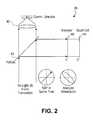
- FIG. 2is a functional block diagram showing an embodiment of a receiver that can use the polarization modulation from the transmitter of FIG. 1 to perform tracking, and further showing diagrams of corresponding polarization states.
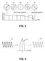
- FIG. 3shows signal diagrams of optical power versus time for an optical data communication signal from the transmitter of FIG. 1 and for a tracking signal from the receiver of FIG. 2, and further shows diagrams of corresponding polarization states.
- FIG. 4illustrates a narrow-band filtering process that may be performed on the tracking signal of FIG. 3 to recover the tracking signal with reduced noise.
- FIG. 5is a functional block diagram of a circuit that can be used by the receiver of FIG. 2 to improve on the recovery of the tracking signal.
- FIG. 6is a plot of output intensity.
- FIG. 7is a plot of the output intensity versus modulator phase retardance.
- FIG. 8is a plot of output intensity versus modulator phase retardance, showing phase offset effects.
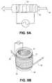
- FIG. 9Ais a perspective drawing of an embodiment of a modulator.
- FIG. 9Bis a perspective drawing of an alternative embodiment of a modulator.
- Embodiments of a system and method for polarization tracking in a wireless optical communication systemare described in detail herein.
- numerous specific detailsare provided, such as the identification of various system components in FIG. 1, to provide a thorough understanding of embodiments of the invention.
- One skilled in the relevant artwill recognize, however, that the invention can be practiced without one or more of the specific details, or with other methods, components, materials, etc.
- well-known structures, materials, or operationsare not shown or described in detail to avoid obscuring aspects of various embodiments of the invention.
- trackingis intended to have a meaning like that understood by those skilled in the art. That is, the term “tracking” more or less includes the monitoring, processing, and adjustment of an orientation of an optical receiver (and/or an orientation of its component parts) with respect to a received optical signal. In this manner, tracking allows the optical receiver to remain substantially aligned with the received optical signal, thereby resulting in maximum reception performance at the optical receiver.
- An embodiment of the inventionuses polarization tracking in order to obtain an alternating (AC) tracking signal, so that the AC tracking signal can be subsequently used to adjust an orientation of an optical receiver with respect to a received optical transmission signal.
- the optical transmission signalcan comprise laser light and the like, at 1548.1 nm, for example.
- the optical transmission signalis not limited to being monochromatic or to any particular wavelength or color, and may include visible light as well as ultraviolet or infrared (IR) portions of the spectrum.
- the embodimentinvolves modulation of the polarization of the optical transmission signal at an optical transmitter, and then, at the optical receiver, using a polarization analyzer positioned in front of a quad cell detector to turn the modulated polarization into an AC amplitude modulated optical signal for tracking. Since the AC amplitude modulation can use a simple sinusoidal tone, a narrow-band electronic filter could be used on resulting signals generated by the quad cell detectors to greatly reduce out-of-band noise.
- a laser sourcesuch as a suitable commercially available distributed feedback (DFB) laser 12
- DFBdistributed feedback
- PMpolarization-maintaining
- a DFB laser 12with more power than conventional DFB lasers may be used.
- the PM fiber 14is connected to an input of an electro-optic modulator 16 , such as a lithium niobate (LiNbO 3 ) modulator.
- the modulator 16can modulate the incoming laser signal with a sinusoidal 100 kHz modulating signal V(t), for example, and it is understood that the modulating signal V(t) can have other frequencies and need not necessarily be a sinusoidal signal (e.g., the modulating signal V(t) can be a triangle wave, square wave, etc).
- the PM fiber 14 of the DFB laser 12produces an output laser light having a linear state of polarization (SOP), which may be vertical with respect to the axes of the PM fiber 14 , as shown in a diagram 18 of FIG. 1 .
- SOPstate of polarization
- the resulting input to the modulator 16is keyed such that the linear polarization coming out of the PM fiber 14 illuminates the axes of the modulator 16 (functioning as an LiNbO 3 waveguide) at 45 degrees, as shown by a diagram 1 of FIG. 1 .
- a PM fiber 20 exiting the modulator 16has its axes aligned with the modulator axes.
- the PM fiber 20may be the same as the PM fiber 14 , or in another embodiment, the PM fiber 20 is not used.
- a sinusoidal voltagesuch as the modulating signal V(t)
- V(t)a sinusoidally varying polarization state
- the applied voltage V(t)effectively creates an electrically induced birefringence in the LiNbO 3 waveguide—its axes of birefringence or eigenaxes are illuminated equally with a 45-degree linear input polarization.
- the modulator 16can comprise a waveguide or crystal that has electrically controllable birefringence.
- This modulated polarization statecan be fed to an input of an amplifier, such as a polarization maintaining erbium-doped fiber amplifier (EDFA) 32 , to amplify the incoming laser light.
- an amplifiersuch as a polarization maintaining erbium-doped fiber amplifier (EDFA) 32
- the EDFA 32need not be used.
- the EDFA 32can be provided with a plurality of PM fibers 34 , each corresponding to a separate transmission link.
- Laser light(s) 36 outputted from the PM fibers 34(e.g., the light transmitted to an optical receiver) can have a SOP shown at a diagram 4 at some instance in time.
- an optical receiver 38that can receive and process the laser light 36 transmitted from the transmitter 10 .
- the laser light 36 received by the receiver 10has its polarization modulated in a manner such as that described above with reference to FIG. 1 .
- other components of the receiver 38are not shown in FIG. 2 .
- Such componentscan include, for example, lenses, mirrors, holographic optical elements, filters, etc.
- the laser light 36is first directed to a beam splitter 40 , which in one embodiment can comprise a pellicle.
- the beam splitter 40functions to split the incoming laser light between a communication detector 42 and a tracking detector, such as a quad cell detector 44 .
- a tracking detectorsuch as a quad cell detector 44 .
- most of the laser light 36is directed to the communication detector 42 , and it is understood that the beam splitter 40 can be designed to split the laser light 36 into any suitable ratio (e.g., 75% to the communication detector 42 and 25% to the quad cell detector 44 ).
- the communication detector 42 and/or quad cell detector 44can comprise any type of suitable photosensitive device, such as photo diodes, avalanche photo diodes, charge coupled devices (CCDs), etc. Furthermore, although a quad cell 44 is described herein as having four optical detectors corresponding to each quadrant, it is to be appreciated that the detector 44 can have any number of detectors and/or regions that detect incident light.
- a properly oriented analyzer 46is positioned in front of the quad cell detector 44 .
- the analyzer 46can be any suitable commercially available device that can detect a polarity of an incoming light.
- the analyzer 46has an axis of transmission, such as that shown in a diagram 6 of FIG. 2, and the analyzer 46 passes the maximum amount of light when the light has a polarization that is aligned with the axis of transmission of the analyzer 46 .
- the analyzer 46can produce a resulting output light signal that has a sinusoidal amplitude modulation, such as a tone signal corresponding to the signal V(t) at 100 kHz of FIG. 1 .
- This amplitude-modulated light signalis then directed to the quad cell detector 44 .
- the relative strength (e.g., power, amplitude, etc.) of the amplitude-modulated light signal incident on each of the quadrants of the quad cell detector 44can then be converted into a corresponding electronic AC signal (e.g., an electronic signal including a tracking signal), which is subsequently used to determine whether the receiver's 38 orientation with respect to the transmitter 10 and/or to the laser light 36 has to be adjusted.
- FIG. 3shows an example of this AC signal at 48 .
- the sinusoidal AC signal 48 for trackingcorresponds to the modulated polarization of the laser light 36 and has a much lower frequency (e.g., is slowly varying) compared to the data communication portion 50 of the laser light 36 .
- FIG. 4illustrates an embodiment of a method to recover a substantially noise-free version of the tracking signal outputted from the quad cell detector.
- the electronic AC signal(s) outputted from the quad cell detector 44may include the tracking signal, noise, and portions of the higher frequency data communication signal, collectively shown at 52 in FIG. 4.
- a narrow-band filter 54 centered at a frequency f of the tracking signal(which may be at the 100 kHz frequency of the signal V(t) of FIG. 1 that was used to modulate the polarization) can be used to filter the noise and data communication signal, thereby recovering a “clean” tracking signal at 56 .
- FIG. 5shows an embodiment of a circuit 58 that can recover the tracking signal from both the f and 2f frequencies. Initially, the quad cell detector 46 outputs electronic AC signal(s) 60 having components at f and 2f.
- a first branch of the circuit 58recovers the 2f component from the electronic AC signal 60 using a first narrow-band filter 62 centered at 2f.
- a second branch of the circuit 58recovers the f component from the electronic AC signal 60 using a second narrow-band filter 64 centered at f.
- the resulting signalsare then fed into respective circuit units, such as full-wave/half-wave rectifier circuits 66 and 68 (or into similar types of circuits, such as absolute value circuits, square-law circuits, lock-in detector circuits, etc).
- Outputs from the rectifier circuits 66 and 68then form inputs into a summer circuit 70 that sums these inputs to get a final signal at 72 . Consequently, the final signal 72 comprises the sum of the amplitudes of the tracking signals at f and 2f from each quadrant of the quad cell detector 44 , and can be compared with each other to determine the relative strength of the optical signals detected by the quad cell detector 44 for tracking purposes.
- the analyzer 46serves a distinctive purpose in the embodiments described herein. That is, without the analyzer 46 , the quad cell detector 44 is largely unaffected by changes in polarization—the quad cell detector 44 cannot “see” the modulated polarization of the laser light 36 but instead can only detected changes in light intensity (e.g., it can detect only the modulation of the laser light's 36 amplitude or power). Accordingly, the analyzer 46 serves to convert the modulated polarization into an amplitude modulation that the quad cell detector 44 can detect. In effect, the analyzer 46 provides a way to turn the portion of the laser light 36 used for tracking completely “on” or completely “off,” thereby potentially providing 100% amplitude modulation that is easily detected by the quad cell detector 44 .
- the purpose of using the PM fibers 14 , 20 , and 34 in the transmitter 10is to hold the rotational state of the polarization constant.
- General manipulation of a PM fibermay alter the birefringence leading to a different polarization ellipticity, but generally does not easily rotate the polarization state.
- Changes in the birefringence of any PM fiber in the transmitter 10changes the phase of the sinusoidal signal (e.g., the phase of the sinusoidally varying polarization state), but does not alter the detected amplitude modulation. Since the transmitter 10 utilizes amplitude and not phase, any effective birefringence change in the transmitter 10 (e.g., in the modulator 16 , PM fiber 14 , EDFA 32 , etc.) generally does not effect the tracking performance.
- Jones Matricesmay be employed to follow the optical/polarization train or diagrams 1 - 6 shown in FIGS. 1-2.
- ⁇ [ E x E y ][ 1 1 1 1 ] [ 1 0 0 e j ⁇ ⁇ ⁇ ⁇ 2 ] [ cos ⁇ ⁇ ( ⁇ ) sin ⁇ ⁇ ( ⁇ ) - sin ⁇ ⁇ ( ⁇ ) cos ⁇ ⁇ ( ⁇ ) ] [ 1 0 0 e j ⁇ ⁇ ⁇ 1 ] [ 1 1 ] ⁇ 1 2 6 5 4 3 2 ⁇ 1 ( 1 )
- Equation (1)the matrices are multiplied from right to left.
- the identifying numbers beneath the matricescorrespond to the reference numbers indicated by the diagrams 1 - 6 of FIGS. 1 and 2.
- the first matrixcorresponds to linear input polarization on the modulator's 16 input that is 45 degrees relative to the LiNbO 3 eigenaxes.
- the second matrixcorresponds to the electrically induced birefringence of the modulator 16 .
- the third matrixis the rotation of the polarization ellipse by some arbitrary angle ⁇ —this could occur if the fiber at this point were not polarization maintaining.
- the fourth matrixaccounts for arbitrary birefringence induced by the PM fiber 20 between the modulator 16 and the EDFA 32 , and any birefringence of the fiber within the EDFA 32 .
- the output E-field from the analyzer 46is given by Ex and Ey of the fifth matrix.
- the corresponding output intensity on one axisis given by:
- Equation (2)Setting ⁇ 2 to zero in Equation (2) for the moment, and plotting the normalized output intensity I ox (t) from the quad cell detector 44 as a function of ⁇ and ⁇ 1 produces a plot 74 of FIG. 6, where the ⁇ axis is on the left; the ⁇ 1 axis is at the front; and the scale on the axes (0 to 100) corresponds to 0 to ⁇ radians. It is evident that the modulation depth can go to zero for a given analyzer rotation because of undesired rotations of the polarization ellipse in the system (such as from twists in a non-polarization maintaining fiber).
- loxis plotted versus the modulator 16 phase retardance for various values of the polarization rotation ⁇ in waveforms 76 of FIG. 7 . From FIGS. 6 and 7, certain values of the rotation swill lead to no amplitude modulation.
- the idea of using polarization-maintaining components in the transmitter 10 of FIG. 1is to prevent such rotation from occurring, and so one fixed analyzer 46 position at the quad cell detector 44 can give full modulation. Without PM fiber in the transmitter 10 , it may be necessary to have an automatically rotatable analyzer 46 at the quad cell detector 46 in order to keep the amplitude modulation at the quad cell detector 46 at a maximum. Since such rotational changes are generally slowly varying, it is possible in an embodiment to use a control loop to keep the modulation depth peaked-up at the quad cell detector 44 by rotating the analyzer 46 for a maximum, if polarization maintaining components were not used.
- the modulator 16can be driven with a substantially symmetric triangle wave voltage that produces a peak phase change of 2 ⁇ .
- Equation (3) in Equation (2)can produce the sinusoidal tone of FIG. 7.
- a peak applied voltage used at the modulator 16 to get 2 ⁇ phasecan be approximately 10 V in an embodiment.
- the effect of varying birefringence in the PM fiber 14is to simply shift the phase offset of the amplitude modulation on the quad cell detector 44 . This is modeled by a changing ⁇ 2 in Equation (2), which produces the waveforms 78 of FIG. 8 —the phase offset changes, but not the modulation depth.
- the modulator 16can be replaced with any suitable device that can changes the polarization sufficiently to get an adequate signal on the quad cell detector 44 .
- suitable devicescan include:
- a Faraday rotatorthat uses a time-changing magnetic field to rotate the polarization (as opposed to using an electric field) at the output of the DFB laser 12 .
- An example of such a modulatoris shown in FIG. 9A, where a coil 80 of wire is wound around a Faraday rotator material 82 . An alternating current is applied to the coil 80 , and this time-varying electric field causes a time-varying magnetic field which changes the polarization of the incoming light signal 84 .
- the transmitter 10is designed to mitigate random changes in the circular birefringence, in order to prevent a reduction in amplitude modulation at the quad cell detector.
- FIG. 9 BA device which stretches or otherwise stresses a fiber in such way as to cause an induced birefringence.
- An examplewould be a twisted fiber wound tightly on a piezo cylinder or on a mandrel cylinder, as shown in FIG. 9 B.
- the figureillustrates a fiber 86 wound into a coil 88 around a piezo or mandrel cylinder 90 having an inner electrode 94 and an outer electrode 92 .
- a drive voltage applied to the piezo cylinderwould expand the cylinder, creating a birefringence on the fiber.
- the effect on the polarizationwould be substantially the same as that achieved with an electro-optic modulator, such as the modulator 16 .
- a rotating half-wave plate at the output of the DFB laser 12(similar in effect to the Faraday rotator), or a rotating quarter-wave plate (effect similar to the E-O modulator), driven mechanically by a motor.
- Another embodimenteliminates or reduces the need for polarization maintaining EDFAs or splitters by monitoring the polarization state from the EDFA's 32 output, and then feeding back a signal that would change the EDFA's 32 input polarization state to achieve polarization stability.
- polarization controllersare commercially available from companies like E-Tek (Model FPCR). Basically, the polarization controller is placed between the DFB laser 12 and the EDFA 32 input. Changes in the polarization state at the EDFA 32 output fiber is detected and compensated for by changing the input controls on the polarization controller.
- Yet another embodimentcan modulate both the orientation of the polarization ellipse and the ellipticity in order to always produce some signal at the quad cell detector 44 , regardless of what the optical system (e.g., the transmitter 10 ) is doing to the polarization.
- a modulatoris produced by E-Tek as well.
- This embodimenthas the advantage of not requiring polarization-maintaining components, but does not produce a pure modulation tone on the quad cell detector 44 .
- Such an embodimentmay require synchronization of the two modulation drive signals, to prevent a drift in relative signal strength on the quad cell detector 44 .
- Another embodimentcan use a rotating analyzer 44 at the quad cell detector 44 in order to keep the quad signal peaked-up when the polarization gets inadvertently rotated (e.g., if PM fiber is not used in the transmitter 10 ).
- This embodimentfunctions if little or no linear birefringence were induced by the components of the transmitter 10 , which is would occur if non-PM fiber is used and is not bent or wound in tight loops.
- the polarization tracking systemcan operate at IR frequencies
- the systemcan use a narrow-band electronic filter (1-10 kHz, for example) in the electronics of the quad cell detector 44 to filter out wide-band noise (in contrast to data tracking which has a bandwidth of ⁇ 200 MHz-all else being equal, this narrower filter can increase the tracking sensitivity by one to two orders of magnitude compared to data tracking, depending on the electronic filter noise and actual filter bandwidth used); and
- Varying the data rate of the data communication signalhas no effect on tracking electronics performance, and similarly, full 100% modulation of the polarization for tracking purposes has substantially no adverse effect on the data communication signal.
Landscapes
- Physics & Mathematics (AREA)
- Electromagnetism (AREA)
- Engineering & Computer Science (AREA)
- Computer Networks & Wireless Communication (AREA)
- Signal Processing (AREA)
- Optical Communication System (AREA)
Abstract
Description


Claims (40)
Priority Applications (3)
| Application Number | Priority Date | Filing Date | Title |
|---|---|---|---|
| US09/627,279US6490070B1 (en) | 2000-07-28 | 2000-07-28 | Method and apparatus for polarization tracking in wireless optical communication systems |
| AU2001275153AAU2001275153A1 (en) | 2000-07-28 | 2001-06-01 | Method and apparatus for polarization tracking in wireless optical communication systems |
| PCT/US2001/017860WO2002011298A2 (en) | 2000-07-28 | 2001-06-01 | Method and apparatus for polarization tracking in wireless optical communication systems |
Applications Claiming Priority (1)
| Application Number | Priority Date | Filing Date | Title |
|---|---|---|---|
| US09/627,279US6490070B1 (en) | 2000-07-28 | 2000-07-28 | Method and apparatus for polarization tracking in wireless optical communication systems |
Publications (1)
| Publication Number | Publication Date |
|---|---|
| US6490070B1true US6490070B1 (en) | 2002-12-03 |
Family
ID=24514002
Family Applications (1)
| Application Number | Title | Priority Date | Filing Date |
|---|---|---|---|
| US09/627,279Expired - LifetimeUS6490070B1 (en) | 2000-07-28 | 2000-07-28 | Method and apparatus for polarization tracking in wireless optical communication systems |
Country Status (3)
| Country | Link |
|---|---|
| US (1) | US6490070B1 (en) |
| AU (1) | AU2001275153A1 (en) |
| WO (1) | WO2002011298A2 (en) |
Cited By (11)
| Publication number | Priority date | Publication date | Assignee | Title |
|---|---|---|---|---|
| US20030063848A1 (en)* | 2001-09-28 | 2003-04-03 | Burns William K. | High power, low noise, superflourescent device and methods related thereto |
| US20030206691A1 (en)* | 1996-05-06 | 2003-11-06 | Puzey Kenneth A. | High speed data link and transmitter in the mid-infrared wavelength range |
| US6674974B1 (en) | 2000-07-28 | 2004-01-06 | Terabeam Corporation | Method and apparatus for tracking in an optical communications system |
| US6768876B1 (en)* | 2000-07-28 | 2004-07-27 | Terabeam Corporation | Method and apparatus for tracking an optical communications system |
| US6801722B1 (en)* | 2001-05-01 | 2004-10-05 | Terabeam Corporation | Optical tracking system with reflective fiber |
| US20050276608A1 (en)* | 2000-10-16 | 2005-12-15 | Andrew Pavelchek | Establishment and maintenance of optical links between optical transceiver nodes in free-space optical communications networks |
| US20070154225A1 (en)* | 2005-12-30 | 2007-07-05 | Craig Schulz | Optical receiver with duo-binary encoder |
| US20070297808A1 (en)* | 2005-05-17 | 2007-12-27 | Andrew Pavelchek | Establishment and maintenance of optical links between optical transceiver nodes in free-space optical communications networks |
| US10419975B1 (en)* | 2015-12-11 | 2019-09-17 | Spectranet, Inc. | Parallel multi-bit low latency wireless messaging |
| US11307367B2 (en)* | 2020-08-17 | 2022-04-19 | X Development Llc | Method of precision beam collimation using fiber-optic circulator and wavelength tunable source |
| US20240113779A1 (en)* | 2022-09-30 | 2024-04-04 | Airbus (S.A.S.) | Free space optical communications terminal |
Citations (24)
| Publication number | Priority date | Publication date | Assignee | Title |
|---|---|---|---|---|
| US3569715A (en)* | 1968-09-05 | 1971-03-09 | Atomic Energy Commission | Electro-optical telemetry system receiver utilizing negative feedback to eliminate atmospherically induced low frequency light beam intensity variations |
| US3971930A (en)* | 1974-04-24 | 1976-07-27 | The United States Of America As Represented By The Administrator Of The National Aeronautics And Space Administration | Polarization compensator for optical communications |
| US4633315A (en) | 1983-04-01 | 1986-12-30 | U.S. Philips Corporation | Receiver for RF-signals comprising a pair of parallel signal paths |
| US5023948A (en)* | 1985-06-19 | 1991-06-11 | British Telecommunications Public Limited Company | Polarization modulation of optical signals using birefringent medium |
| US5062150A (en) | 1989-01-23 | 1991-10-29 | Massachusetts Institute Of Technology | Fiber-based free-space optical system |
| US5142400A (en)* | 1989-12-26 | 1992-08-25 | Cubic Corporation | Method and apparatus for automatic acquisition and alignment of an optical beam communication link |
| US5355381A (en)* | 1992-12-03 | 1994-10-11 | Amoco Corporation | Self-heterodyne optical fiber communications system |
| US5539557A (en) | 1993-04-21 | 1996-07-23 | Kokusai Denshin Denwa Kabushiki Kaisha | Supervisory signal receiving method and apparatus |
| US5576871A (en)* | 1994-07-25 | 1996-11-19 | The Furukawa Electric Co., Ltd. | Method for optical communications |
| US5627669A (en)* | 1991-11-13 | 1997-05-06 | Canon Kabushiki Kaisha | Optical transmitter-receiver |
| US5633959A (en)* | 1994-10-11 | 1997-05-27 | Advantest Corporation | Polarization state changing apparatus and polarization degree measuring apparatus using the same |
| US5710652A (en) | 1992-08-27 | 1998-01-20 | Trex Communications | Laser communication transceiver and system |
| US5777768A (en) | 1995-09-01 | 1998-07-07 | Astroterra Corporation | Multiple transmitter laser link |
| US5790291A (en) | 1995-12-07 | 1998-08-04 | Lucent Technologies Inc. | Beam steering and tracking of laser communication links by dual-quadrant tracker and photodiode assembly |
| US5808768A (en)* | 1994-11-16 | 1998-09-15 | The Furukawa Electric Co., Ltd. | Optical telecommunications system |
| US5946119A (en) | 1997-02-12 | 1999-08-31 | Tyco Submarine Systems Ltd. | Wavelength division multiplexed system employing optimal channel modulation |
| US6023362A (en)* | 1997-05-08 | 2000-02-08 | Lucent Technologies Inc. | Optical transmitter having pre-modulation amplification |
| US6025948A (en) | 1996-02-13 | 2000-02-15 | Alcatel Submarine Networks | Optical signal transmission installation including a repeater monitoring system |
| US6057950A (en)* | 1994-09-27 | 2000-05-02 | Tyco Submarine Systems, Ltd. | Synchronous polarization and phase modulation for improved performance of optical transmission systems |
| US6091528A (en) | 1996-12-17 | 2000-07-18 | Kabushiki Kaisha Toshiba | Optical communication system of space propagation type |
| US6097522A (en) | 1996-12-06 | 2000-08-01 | Oerlikon Contraves Ag | Method and device for aligning an optical transmission and reception beam in satellite connections |
| US6141140A (en)* | 1997-12-08 | 2000-10-31 | Samsung Electronics Co., Ltd. | Optical modulator using isolator and optical transmitter including the same |
| US6219133B1 (en) | 1997-10-09 | 2001-04-17 | Seiko Epson Corporation | Spatial optical transmission device and method of spatial optical transmission |
| US6271953B1 (en) | 1998-09-02 | 2001-08-07 | Harris Corporation | Method and system for optical free space communications using non-mechanical beam steering |
- 2000
- 2000-07-28USUS09/627,279patent/US6490070B1/ennot_activeExpired - Lifetime
- 2001
- 2001-06-01AUAU2001275153Apatent/AU2001275153A1/ennot_activeAbandoned
- 2001-06-01WOPCT/US2001/017860patent/WO2002011298A2/enactiveApplication Filing
Patent Citations (24)
| Publication number | Priority date | Publication date | Assignee | Title |
|---|---|---|---|---|
| US3569715A (en)* | 1968-09-05 | 1971-03-09 | Atomic Energy Commission | Electro-optical telemetry system receiver utilizing negative feedback to eliminate atmospherically induced low frequency light beam intensity variations |
| US3971930A (en)* | 1974-04-24 | 1976-07-27 | The United States Of America As Represented By The Administrator Of The National Aeronautics And Space Administration | Polarization compensator for optical communications |
| US4633315A (en) | 1983-04-01 | 1986-12-30 | U.S. Philips Corporation | Receiver for RF-signals comprising a pair of parallel signal paths |
| US5023948A (en)* | 1985-06-19 | 1991-06-11 | British Telecommunications Public Limited Company | Polarization modulation of optical signals using birefringent medium |
| US5062150A (en) | 1989-01-23 | 1991-10-29 | Massachusetts Institute Of Technology | Fiber-based free-space optical system |
| US5142400A (en)* | 1989-12-26 | 1992-08-25 | Cubic Corporation | Method and apparatus for automatic acquisition and alignment of an optical beam communication link |
| US5627669A (en)* | 1991-11-13 | 1997-05-06 | Canon Kabushiki Kaisha | Optical transmitter-receiver |
| US5710652A (en) | 1992-08-27 | 1998-01-20 | Trex Communications | Laser communication transceiver and system |
| US5355381A (en)* | 1992-12-03 | 1994-10-11 | Amoco Corporation | Self-heterodyne optical fiber communications system |
| US5539557A (en) | 1993-04-21 | 1996-07-23 | Kokusai Denshin Denwa Kabushiki Kaisha | Supervisory signal receiving method and apparatus |
| US5576871A (en)* | 1994-07-25 | 1996-11-19 | The Furukawa Electric Co., Ltd. | Method for optical communications |
| US6057950A (en)* | 1994-09-27 | 2000-05-02 | Tyco Submarine Systems, Ltd. | Synchronous polarization and phase modulation for improved performance of optical transmission systems |
| US5633959A (en)* | 1994-10-11 | 1997-05-27 | Advantest Corporation | Polarization state changing apparatus and polarization degree measuring apparatus using the same |
| US5808768A (en)* | 1994-11-16 | 1998-09-15 | The Furukawa Electric Co., Ltd. | Optical telecommunications system |
| US5777768A (en) | 1995-09-01 | 1998-07-07 | Astroterra Corporation | Multiple transmitter laser link |
| US5790291A (en) | 1995-12-07 | 1998-08-04 | Lucent Technologies Inc. | Beam steering and tracking of laser communication links by dual-quadrant tracker and photodiode assembly |
| US6025948A (en) | 1996-02-13 | 2000-02-15 | Alcatel Submarine Networks | Optical signal transmission installation including a repeater monitoring system |
| US6097522A (en) | 1996-12-06 | 2000-08-01 | Oerlikon Contraves Ag | Method and device for aligning an optical transmission and reception beam in satellite connections |
| US6091528A (en) | 1996-12-17 | 2000-07-18 | Kabushiki Kaisha Toshiba | Optical communication system of space propagation type |
| US5946119A (en) | 1997-02-12 | 1999-08-31 | Tyco Submarine Systems Ltd. | Wavelength division multiplexed system employing optimal channel modulation |
| US6023362A (en)* | 1997-05-08 | 2000-02-08 | Lucent Technologies Inc. | Optical transmitter having pre-modulation amplification |
| US6219133B1 (en) | 1997-10-09 | 2001-04-17 | Seiko Epson Corporation | Spatial optical transmission device and method of spatial optical transmission |
| US6141140A (en)* | 1997-12-08 | 2000-10-31 | Samsung Electronics Co., Ltd. | Optical modulator using isolator and optical transmitter including the same |
| US6271953B1 (en) | 1998-09-02 | 2001-08-07 | Harris Corporation | Method and system for optical free space communications using non-mechanical beam steering |
Cited By (15)
| Publication number | Priority date | Publication date | Assignee | Title |
|---|---|---|---|---|
| US20030206691A1 (en)* | 1996-05-06 | 2003-11-06 | Puzey Kenneth A. | High speed data link and transmitter in the mid-infrared wavelength range |
| US6674974B1 (en) | 2000-07-28 | 2004-01-06 | Terabeam Corporation | Method and apparatus for tracking in an optical communications system |
| US6768876B1 (en)* | 2000-07-28 | 2004-07-27 | Terabeam Corporation | Method and apparatus for tracking an optical communications system |
| US20050276608A1 (en)* | 2000-10-16 | 2005-12-15 | Andrew Pavelchek | Establishment and maintenance of optical links between optical transceiver nodes in free-space optical communications networks |
| US6801722B1 (en)* | 2001-05-01 | 2004-10-05 | Terabeam Corporation | Optical tracking system with reflective fiber |
| US6744947B2 (en)* | 2001-09-28 | 2004-06-01 | The United States Of America As Represented By The Secretary Of The Navy | High power, low noise, fluorescent device and methods related thereto |
| US20030063848A1 (en)* | 2001-09-28 | 2003-04-03 | Burns William K. | High power, low noise, superflourescent device and methods related thereto |
| US20070297808A1 (en)* | 2005-05-17 | 2007-12-27 | Andrew Pavelchek | Establishment and maintenance of optical links between optical transceiver nodes in free-space optical communications networks |
| US20070154225A1 (en)* | 2005-12-30 | 2007-07-05 | Craig Schulz | Optical receiver with duo-binary encoder |
| US7574145B2 (en)* | 2005-12-30 | 2009-08-11 | Intel Corporation | Optical receiver with duo-binary encoder |
| US10419975B1 (en)* | 2015-12-11 | 2019-09-17 | Spectranet, Inc. | Parallel multi-bit low latency wireless messaging |
| US11307367B2 (en)* | 2020-08-17 | 2022-04-19 | X Development Llc | Method of precision beam collimation using fiber-optic circulator and wavelength tunable source |
| US11747578B2 (en) | 2020-08-17 | 2023-09-05 | X Development Llc | Method of precision beam collimation using fiberoptic circulator and wavelength tunable source |
| US12217885B2 (en) | 2020-08-17 | 2025-02-04 | X Development Llc | Method of precision beam collimation using fiber-optic circulator and wavelength tunable source |
| US20240113779A1 (en)* | 2022-09-30 | 2024-04-04 | Airbus (S.A.S.) | Free space optical communications terminal |
Also Published As
| Publication number | Publication date |
|---|---|
| WO2002011298A2 (en) | 2002-02-07 |
| WO2002011298A3 (en) | 2002-07-25 |
| AU2001275153A1 (en) | 2002-02-13 |
Similar Documents
| Publication | Publication Date | Title |
|---|---|---|
| EP0630122B1 (en) | Apparatus and method employing fast polarization modulation to reduce effects of polarization hole burning and polarization dependent loss | |
| US8200087B2 (en) | Method and device for stabilizing the state of polarization of a polarization multiplexed optical radiation | |
| Billault et al. | Free space optical communication receiver based on a spatial demultiplexer and a photonic integrated coherent combining circuit | |
| US6678431B2 (en) | Method for compensating polarization mode dispersion occurring in optical transmission fiber and apparatus therefor | |
| DE69529392T2 (en) | Polarization diversity detection of optical signals through a polarization mode dispersive medium | |
| US6654105B2 (en) | Cross-correlating PMD detector | |
| US6490070B1 (en) | Method and apparatus for polarization tracking in wireless optical communication systems | |
| US5986784A (en) | Adaptive polarization diversity detection scheme for coherent communications and interferometric fiber sensors | |
| US5063290A (en) | All-optical fiber faraday rotation current sensor with heterodyne detection technique | |
| EP0758090B1 (en) | An electromagnetic wave-to-optical signal converting and modulating device and a communication system using the same | |
| JPH0787428B2 (en) | Digital information transmission method and apparatus | |
| JPH03210841A (en) | Optical fiber communication system | |
| EP0803995A2 (en) | High-speed optical polarization scrambler with adjustable chirp | |
| CN104779997A (en) | Polarization modulation space laser communication method based on Stokes parameter identification | |
| US6671056B2 (en) | Method and system for optical spectrum analysis with a depolarized local oscillator signal | |
| CN114553421B (en) | Quantum key distribution decoding device for immune channel disturbance | |
| EP0639900B1 (en) | Improved apparatus and method employing polarization modulation to reduce effects of polarization hole burning and/or polarization dependent loss | |
| JPH11237594A (en) | Optical modulator using isolator and optical transmission device having the same | |
| CA2338343A1 (en) | System for minimising or compensating pmd-induced distortions in optical transmission systems and transmision fibres in particular | |
| US7171082B2 (en) | Method and apparatus for optical top-hat pulse generation | |
| KR100483023B1 (en) | Polarization mode dispersion compensating device in optical transmission system and method thereof | |
| EP3625623B1 (en) | Optical device | |
| Ghosh et al. | Simple direct-detection-based Stokes vector receiver circuit on InP | |
| JPS63229926A (en) | Optical communication method | |
| Frigo et al. | Polarization-dependent loss in polarization modulated photonic links: model and experiment |
Legal Events
| Date | Code | Title | Description |
|---|---|---|---|
| AS | Assignment | Owner name:TERABEAM INTERNET SYSTEMS, WASHINGTON Free format text:ASSIGNMENT OF ASSIGNORS INTEREST;ASSIGNORS:ADAMS, JEFFREY C.;PRATT, MARK;BARCLAY, MICAH J.;REEL/FRAME:011293/0283;SIGNING DATES FROM 20000719 TO 20001101 | |
| AS | Assignment | Owner name:TERABEAM LABS, L.L.C., WASHINGTON Free format text:CHANGE OF NAME;ASSIGNOR:TERABEAM INTERNET SYSTEMS;REEL/FRAME:011513/0800 Effective date:20001109 | |
| AS | Assignment | Owner name:TERABEAM CORPORATION, WASHINGTON Free format text:ASSIGNMENT OF ASSIGNORS INTEREST;ASSIGNOR:TERABEAM LABS, L.L.C.;REEL/FRAME:011794/0517 Effective date:20010430 | |
| STCF | Information on status: patent grant | Free format text:PATENTED CASE | |
| FPAY | Fee payment | Year of fee payment:4 | |
| FEPP | Fee payment procedure | Free format text:PAYOR NUMBER ASSIGNED (ORIGINAL EVENT CODE: ASPN); ENTITY STATUS OF PATENT OWNER: LARGE ENTITY | |
| AS | Assignment | Owner name:TERABEAM LABS, L.L.C., WASHINGTON Free format text:CORRECTIVE ASSIGNMENT TO CORRECT THE NAME OF THE ASSIGNOR PREVIOUSLY RECORDED ON REEL 011513 FRAME 0800. ASSIGNOR(S) HEREBY CONFIRMS THE CHANGE OF NAME.;ASSIGNOR:TERABEAM INTERNET SYSTEMS, L.L.C.;REEL/FRAME:020986/0558 Effective date:20001109 | |
| AS | Assignment | Owner name:PERTEX TELECOMMUNICATION LLC, DELAWARE Free format text:ASSIGNMENT OF ASSIGNORS INTEREST;ASSIGNOR:TERABEAM CORPORATION;REEL/FRAME:021557/0044 Effective date:20080523 | |
| FEPP | Fee payment procedure | Free format text:PAYOR NUMBER ASSIGNED (ORIGINAL EVENT CODE: ASPN); ENTITY STATUS OF PATENT OWNER: LARGE ENTITY Free format text:PAYER NUMBER DE-ASSIGNED (ORIGINAL EVENT CODE: RMPN); ENTITY STATUS OF PATENT OWNER: LARGE ENTITY | |
| FPAY | Fee payment | Year of fee payment:8 | |
| FPAY | Fee payment | Year of fee payment:12 | |
| AS | Assignment | Owner name:OL SECURITY LIMITED LIABILITY COMPANY, DELAWARE Free format text:MERGER;ASSIGNOR:PERTEX TELECOMMUNICATION LLC;REEL/FRAME:037392/0187 Effective date:20150826 |