US6490039B2 - Optical sensing based on whispering-gallery-mode microcavity - Google Patents
Optical sensing based on whispering-gallery-mode microcavityDownload PDFInfo
- Publication number
- US6490039B2 US6490039B2US09/925,713US92571301AUS6490039B2US 6490039 B2US6490039 B2US 6490039B2US 92571301 AUS92571301 AUS 92571301AUS 6490039 B2US6490039 B2US 6490039B2
- Authority
- US
- United States
- Prior art keywords
- optical
- sample
- optical resonator
- resonator
- whispering gallery
- Prior art date
- Legal status (The legal status is an assumption and is not a legal conclusion. Google has not performed a legal analysis and makes no representation as to the accuracy of the status listed.)
- Expired - Lifetime
Links
- 230000003287optical effectEffects0.000titleclaimsdescription129
- 238000000034methodMethods0.000claimsabstractdescription30
- 230000008859changeEffects0.000claimsdescription41
- 230000008878couplingEffects0.000claimsdescription20
- 238000010168coupling processMethods0.000claimsdescription20
- 238000005859coupling reactionMethods0.000claimsdescription20
- 238000005259measurementMethods0.000claimsdescription19
- 230000001052transient effectEffects0.000claimsdescription11
- 239000000126substanceSubstances0.000claimsdescription10
- 230000005672electromagnetic fieldEffects0.000claimsdescription7
- 230000003993interactionEffects0.000claimsdescription7
- 230000008569processEffects0.000claimsdescription6
- 239000000523sampleSubstances0.000description51
- 239000000463materialSubstances0.000description13
- 239000004005microsphereSubstances0.000description13
- 239000012491analyteSubstances0.000description12
- 239000000835fiberSubstances0.000description12
- 238000001228spectrumMethods0.000description12
- 238000001514detection methodMethods0.000description9
- 239000011248coating agentSubstances0.000description8
- 238000000576coating methodMethods0.000description8
- 230000003595spectral effectEffects0.000description7
- OKKJLVBELUTLKV-UHFFFAOYSA-NMethanolChemical compoundOCOKKJLVBELUTLKV-UHFFFAOYSA-N0.000description6
- 230000002123temporal effectEffects0.000description6
- 239000003989dielectric materialSubstances0.000description5
- VYPSYNLAJGMNEJ-UHFFFAOYSA-Nsilicon dioxideInorganic materialsO=[Si]=OVYPSYNLAJGMNEJ-UHFFFAOYSA-N0.000description5
- 239000012530fluidSubstances0.000description4
- 230000007246mechanismEffects0.000description4
- 238000012545processingMethods0.000description4
- 238000010521absorption reactionMethods0.000description3
- 239000000427antigenSubstances0.000description3
- 238000006243chemical reactionMethods0.000description3
- 239000011521glassSubstances0.000description3
- 239000007788liquidSubstances0.000description3
- 239000002245particleSubstances0.000description3
- 230000009467reductionEffects0.000description3
- CSCPPACGZOOCGX-UHFFFAOYSA-NAcetoneChemical compoundCC(C)=OCSCPPACGZOOCGX-UHFFFAOYSA-N0.000description2
- LFQSCWFLJHTTHZ-UHFFFAOYSA-NEthanolChemical compoundCCOLFQSCWFLJHTTHZ-UHFFFAOYSA-N0.000description2
- 102000036639antigensHuman genes0.000description2
- 108091007433antigensProteins0.000description2
- 230000008901benefitEffects0.000description2
- 230000001419dependent effectEffects0.000description2
- 238000001914filtrationMethods0.000description2
- 239000010410layerSubstances0.000description2
- 238000009304pastoral farmingMethods0.000description2
- 239000010453quartzSubstances0.000description2
- 230000035945sensitivityEffects0.000description2
- 239000007787solidSubstances0.000description2
- XLYOFNOQVPJJNP-UHFFFAOYSA-NwaterSubstancesOXLYOFNOQVPJJNP-UHFFFAOYSA-N0.000description2
- 239000004793PolystyreneSubstances0.000description1
- 108010090804StreptavidinProteins0.000description1
- 238000013459approachMethods0.000description1
- 238000003556assayMethods0.000description1
- 230000005540biological transmissionEffects0.000description1
- 238000005516engineering processMethods0.000description1
- 238000002474experimental methodMethods0.000description1
- 239000005350fused silica glassSubstances0.000description1
- 239000007789gasSubstances0.000description1
- 150000004676glycansChemical class0.000description1
- 238000011835investigationMethods0.000description1
- 238000004519manufacturing processMethods0.000description1
- 238000000691measurement methodMethods0.000description1
- 239000002184metalSubstances0.000description1
- 230000004048modificationEffects0.000description1
- 238000012986modificationMethods0.000description1
- 229920000344molecularly imprinted polymerPolymers0.000description1
- 238000012544monitoring processMethods0.000description1
- 239000003960organic solventSubstances0.000description1
- 239000004033plasticSubstances0.000description1
- 229920003023plasticPolymers0.000description1
- 230000010287polarizationEffects0.000description1
- 238000005498polishingMethods0.000description1
- 239000004417polycarbonateSubstances0.000description1
- 229920000515polycarbonatePolymers0.000description1
- 229920000642polymerPolymers0.000description1
- 229920001282polysaccharidePolymers0.000description1
- 239000005017polysaccharideSubstances0.000description1
- 229920002223polystyrenePolymers0.000description1
- 108090000623proteins and genesProteins0.000description1
- 102000004169proteins and genesHuman genes0.000description1
- 230000005855radiationEffects0.000description1
- 239000013074reference sampleSubstances0.000description1
- 239000000377silicon dioxideSubstances0.000description1
- 239000002356single layerSubstances0.000description1
- 238000001179sorption measurementMethods0.000description1
- 238000010183spectrum analysisMethods0.000description1
- 238000010408sweepingMethods0.000description1
- 230000007704transitionEffects0.000description1
Images


Classifications
- H—ELECTRICITY
- H01—ELECTRIC ELEMENTS
- H01S—DEVICES USING THE PROCESS OF LIGHT AMPLIFICATION BY STIMULATED EMISSION OF RADIATION [LASER] TO AMPLIFY OR GENERATE LIGHT; DEVICES USING STIMULATED EMISSION OF ELECTROMAGNETIC RADIATION IN WAVE RANGES OTHER THAN OPTICAL
- H01S5/00—Semiconductor lasers
- H01S5/10—Construction or shape of the optical resonator, e.g. extended or external cavity, coupled cavities, bent-guide, varying width, thickness or composition of the active region
- H01S5/1071—Ring-lasers
- H01S5/1075—Disk lasers with special modes, e.g. whispering gallery lasers
- G—PHYSICS
- G01—MEASURING; TESTING
- G01N—INVESTIGATING OR ANALYSING MATERIALS BY DETERMINING THEIR CHEMICAL OR PHYSICAL PROPERTIES
- G01N21/00—Investigating or analysing materials by the use of optical means, i.e. using sub-millimetre waves, infrared, visible or ultraviolet light
- G01N21/17—Systems in which incident light is modified in accordance with the properties of the material investigated
- G01N21/55—Specular reflectivity
- G01N21/552—Attenuated total reflection
- G—PHYSICS
- G01—MEASURING; TESTING
- G01N—INVESTIGATING OR ANALYSING MATERIALS BY DETERMINING THEIR CHEMICAL OR PHYSICAL PROPERTIES
- G01N21/00—Investigating or analysing materials by the use of optical means, i.e. using sub-millimetre waves, infrared, visible or ultraviolet light
- G01N21/75—Systems in which material is subjected to a chemical reaction, the progress or the result of the reaction being investigated
- G01N21/77—Systems in which material is subjected to a chemical reaction, the progress or the result of the reaction being investigated by observing the effect on a chemical indicator
- G01N21/7703—Systems in which material is subjected to a chemical reaction, the progress or the result of the reaction being investigated by observing the effect on a chemical indicator using reagent-clad optical fibres or optical waveguides
- G01N21/7746—Systems in which material is subjected to a chemical reaction, the progress or the result of the reaction being investigated by observing the effect on a chemical indicator using reagent-clad optical fibres or optical waveguides the waveguide coupled to a cavity resonator
- G—PHYSICS
- G02—OPTICS
- G02B—OPTICAL ELEMENTS, SYSTEMS OR APPARATUS
- G02B6/00—Light guides; Structural details of arrangements comprising light guides and other optical elements, e.g. couplings
- G02B6/24—Coupling light guides
- G02B6/26—Optical coupling means
- G02B6/28—Optical coupling means having data bus means, i.e. plural waveguides interconnected and providing an inherently bidirectional system by mixing and splitting signals
- G02B6/293—Optical coupling means having data bus means, i.e. plural waveguides interconnected and providing an inherently bidirectional system by mixing and splitting signals with wavelength selective means
- G02B6/29331—Optical coupling means having data bus means, i.e. plural waveguides interconnected and providing an inherently bidirectional system by mixing and splitting signals with wavelength selective means operating by evanescent wave coupling
- G02B6/29335—Evanescent coupling to a resonator cavity, i.e. between a waveguide mode and a resonant mode of the cavity
- G02B6/29338—Loop resonators
- G02B6/29341—Loop resonators operating in a whispering gallery mode evanescently coupled to a light guide, e.g. sphere or disk or cylinder
Definitions
- This applicationrelates to techniques and devices for optical sensing and optical detection.
- Optical sensinggenerally uses an optical probe beam to interact with a material to be detected. This interaction between the optical probe beam and the material modifies some aspect of the optical probe beam. A portion of this modified beam, such as the scattered light, the reflected light, or the transmitted light, may be collected and measured to obtain certain information of the material. For example, the optical intensity, phase, spectrum, polarization, or direction of the collected light may be measured either individually or in combination with other parameters to determine the certain information of the material.
- Optical sensingmay be used to achieve a number of advantages.
- the sensingcan be non-invasive and does not alter the material to be measured under proper operating conditions.
- the spectrum of the probe beammay be controlled to selectively interact with only certain optical transitions in specified particles, molecules, or atoms in the material.
- Optical sensingmay also be used to achieve high detection sensitivity and to detect minute amount of a particular material.
- This disclosureincludes optical sensing techniques and devices based on whispering-gallery-mode micro resonators or cavities.
- An optical probe beamis evanescently coupled into at least one whispering gallery mode of such a resonator.
- a sample material to be measuredmay be filled within the resonator or surrounded outside the resonator to interact with and modify the whispering gallery mode or geometry of the resonator.
- the evanescent field outside the resonatoris detected or measured to detect a change caused by the modification. This change is then processed to extract information about the sample material.
- This changemay be reflected as, e.g., a temporal change in the mode structure during a transient period, attenuation in the evanescent field, a frequency shift in the whispering gallery mode and its evanescent field, or a change in efficiency of the evanescent coupling of the probe beam into the resonator or coupling of the energy in the whispering gallery mode out of the resonator.
- the quality factor of the resonator for a particular modemay be measured to extract the information about the sample material by, e.g., measuring the spectral bandwidth of the mode or decay time of the mode.
- the frequency shiftis measured.
- the intensity of light coupled out of the resonatoris measured.
- the resonatormay also be actively controlled, e.g., by using a control signal to adjust its dimension, this control signal required to maintain certain desired conditions can be measured before and after the sample is introduced.
- the change in the control signale.g., its magnitude, may be used to extract information on the sample.
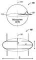
- FIG. 1Ashows a microsphere whispering-gallery-mode cavity to illustrate the general operations of whispering-gallery-mode cavities and two-dimensional curvature confinement.
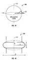
- FIG. 1Bshows an oblate spheroidal microcavity as an example of non-spherical geometries that provide for two-dimensional curvature confinement.
- FIG. 2shows an optical sensing device by using a whispering-gallery-mode (WGM) cavity according to one embodiment.
- WGMwhispering-gallery-mode
- FIGS. 3A, 3 B, 3 C, and 3 Dshow exemplary evanescent coupling schemes that may be used in the optical sensing device in FIG. 2 .
- FIG. 4shows one exemplary flow for measuring a sample by a WGM cavity.
- FIGS. 5A, 5 B, 6 A, and 6 Bshow two different ways of introducing a sample to the WGM cavity for measurement.
- FIG. 7shows three different periods associated with measurements in the system in FIG. 2 .
- FIG. 8shows measured frequency shift in WGM during a transient period after the sample is introduced to a microresonator in FIG. 2 .
- FIG. 1Ashows one embodiment 100 of a micro whispering-gallery-mode resonator formed of a dielectric sphere with a symmetric axis 101 .
- the micro resonator 100generally may be formed from at least a portion of a whole dielectric sphere that includes the equator 110 of the sphere.
- Such a spherical resonatorcan support a special set of resonator modes known as “whispering gallery modes” which are essentially electromagnetic field modes confined in an interior region close to the surface of the sphere around its equator 110 and circulating by total internal reflection inside the axially symmetric dielectric body.
- Microresonatorssuch as microspheres, with dimensions on the order of 10 ⁇ 10 2 microns have been used to form compact optical resonators.
- Such resonatorshave a resonator dimension much larger than the wavelength of light so that the optical loss due to the finite curvature of the resonators can be small.
- the primary sources for optical lossinclude optical absorption in the dielectric material and optical scattering due to the inhomogeneity of the sphere (e.g., irregularities on the sphere surface).
- Qquality factor
- Some microspheres with sub-millimeter dimensionshave been demonstrated to exhibit very high quality factors for light waves, exceeding 10 9 for quartz microspheres.
- optical energyonce coupled into a whispering gallery mode, can circulate at or near the sphere equator with a long cavity storage time.
- the resonator 100may be the whole sphere or a portion of the sphere near the equator 110 that is sufficiently large to support the whispering gallery modes such as rings, disks and other geometries.
- the very high quality factors Q of microspheresmay be attributed to several factors.
- the dielectric materials for microspheresare selected to have ultra-low optical loss at the frequencies of the supported whispering gallery modes. Fiber-grade fused silica may be used for resonators operating at wavelengths near 1.3 and 1.5 microns at which the optical loss is low.
- the surface of the sphereis specially fabricated to minimize the size of any surface inhomogeneities, e.g., on the order of a few Angstroms by processes such as fire polishing.
- the high index contrast in microsphere cavitiesis also used for steep reduction of radiative and scattering losses with increasing radius.
- microsphereshave a curved circumferential edges above and below their equators to provide a two-dimensional curvature confinement to the optical energy in a WGM for grazing reflection of all wave vector components.
- This grazing incidence in a spherecan be essential for minimizing surface scattering that would otherwise limit the Q far below that imposed by attenuation in the material.
- the ring and disksare formed from cylinders with straight side walls. As a result, the light is confined only by a curved geometry along one dimension and effectively bounces from flat surfaces under finite angles. Hence, typical Q-factor of such cavities is limited to about 10 4 ⁇ 10 5 .
- Spherical cavities including at least a portion of a sphere with its equatorare only one type of microcavities that provide two-dimensional curvature confinement for achieving high Q values.
- the micro resonator suitable for the present sensing applicationsmay also have non-spherical resonator geometries that are axially symmetric. Such a non-spherical resonator may be designed to retain the two-dimensional curvature confinement, low scattering loss, and very high Q values of typical spherical resonators (spheres, disks, rings, etc.).
- such a non-spherical resonatormay be formed by distorting a sphere to a non-spherical geometry to purposely achieve a large eccentricity, e.g., greater than 10 ⁇ 1 .
- Such non-spherical microcavitieshave different WGM structures from the spherical counterparts although both have high Q values.
- the spherical cavitieshave a relatively dense spectrum of modes.
- the optical spectrum of the spherehas TE(TM) lmq modes separated by a free spectral range (FSR) defined by the circumference of the sphere and related to consecutive values of the mode index l.
- the mode index lapproximately represent the number of wavelengths that fit into the optical length of the equator, m the number of field maxima in the equator plane, and q the field maxima in the direction along the radius in the equator plane.
- Each of TE(TM) lmq modesis degenerate and includes (2l+1) modes given by the possible values of the mode index m.
- the spherical surfacesare usually not perfectly spherical and have residual nonsphericity. This deviation from the perfect spherical surface lifts the mode degeneracy and breaks down each TE(TM) lmq mode with a given value for the mode index l into a series of observable TE(TM) lmq modes with different values in the mode index m under each value for the mode index l.
- a nonindeal spherical resonatorexhibits two different values for the free spectral range (FSR): a “large” FSR which is the frequency spacing between two adjacent TE(TM) lmq modes with the same values for indices m and q but with a difference of 1 in their l values, and a “small” FSR which is the frequency spacing between two adjacent TE(TM) lmq modes with the same l values but with a difference of 1 in their m values:
- the “large” FSRmay be in the range of 437 to 165 GHz, or in the wavelength scale, 3.5 to 1.3 nm near the center wavelength 1550 nm.
- the “small” FSRmay be in the range of 6.8-2.5 GHz. As a result, even though the spheres are capable of producing a large FSR on the order of hundreds of GHz, the actual spectrum of such spheres are relatively dense with a useful FSR limited by the “small” FSR typically under 10 GHz.
- one way to achieve a FSR on the order of hundreds of GHz in spherical resonators without external spectral filteringis to maintain the mode degeneracy so that the “large” FSR in the whisper gallery modes TE(TM) lmq for given values in the mode index l can be produced in the resonator's spectrum.
- the eccentricity of the sphereshould be minimized.
- non-spherical resonator geometriesformed by distorting a sphere to a non-spherical geometry to purposely achieve a large eccentricity, e.g., greater than 10 ⁇ 1 .
- FIG. 1Bshows an oblate spheroidal microcavity or microtorus as one example of such non-spherical microcavities.
- FIG. 1Bshows one embodiment of a spheriodal microcavity 101 formed of an optical dielectric material.
- the cavity 100is formed by revolving an ellipse around a symmetric axis along the short elliptical axis 101 .
- the lengths of the long and short elliptical axesare a and b, respectively.
- the dimension D of the spheroid 100may be less than 10 mm for operations in the optical and microwave spectral ranges.
- the eccentricitymay be greater than 0.5.
- the central portion of the resonatorsmay be removed to have a hollow central region.
- Such a ring-like spherical or spheroidal configurationscan support the WGMs as long as a sufficient volume remains near the equator to contain the WGM.
- Optical energycan be coupled into the above resonators by evanescent coupling, e.g., using an optical coupler near the resonator 100 or 102 by less than one wavelength of the optical radiation to be coupled.
- evanescent couplinge.g., using an optical coupler near the resonator 100 or 102 by less than one wavelength of the optical radiation to be coupled.
- a whispering gallery modeconfined within the resonator 100 or 102
- its evanescent field 120“leaks” outside the resonator 100 or 102 within a distance about one wavelength of the optical signal, the extent of evanescent wavelength propagation being dependent on the mismatch of refractive indices of the resonator material and surrounding medium.
- the optical couplermay have a receiving terminal to receive an input optical wave at a selected wavelength and a coupling terminal to evanescently couple the optical wave into the resonator 100 or 102 .
- the optical couplermay also be used to couple the optical energy in one or more whispering gallery modes out of the resonator 100 to produce an optical output.
- the outputmay be coupled to an optical detector to convert the information into electronic form or an optical device or system for photonic processing, optical storage, or optical transmission such as a fiber link.
- the input optical beammay be generated from a light source such as a laser.
- FIG. 2shows one embodiment of an optical sensing device 200 by using a micro WGM resonator 201 .
- An evanescent coupler 210is used to couple an input beam 214 from a light source 220 to the resonator 201 via an evanescent field 212 .
- the coupler 210may also couple energy out of the resonator 201 to produce an output optical signal 216 .
- An optical detection module 230is used to receive and detect the signal 216 to produce a detector signal 232 .
- a signal processing module 240processes the signal 232 to produce the desired measurement of the sample.
- the processing module 240may include a microprocessor to process and infer the desired property of the sample from the information in the detector signal 232 .
- the evanescent coupler 210may be implemented by using one or two angle-polished fibers or waveguides 210 A and 210 B as shown in FIG. 3 A. Such fibers or waveguides are generally designed to support a single mode.
- the angle-polished tipis placed near the resonator 201 to effectuate the evanescent coupling.
- the index of refraction of the fibers or waveguides 210 A and 210 Bis greater than that of the resonator 201 , and the optimal angle of the polish has to be chosen depending on the ratio of indices. See, e.g., V. S. Ilchenko, X. S. Yao, L. Maleki, Optics Letters, Vol.24, 723(1999).
- evanescent coupler 210may be implemented by using one or two micro prisms 210 C and 210 D as shown in FIG. 3B.
- a single angle-polished waveguide or fiber, or a single micro prism 310 or 320may be used to operate as the evanescent coupler 210 to couple both the input wave 214 and the output wave 216 as shown in FIGS. 3C and 3D.
- An angle-polished fibercan also be used without assistance of a prism to for both input and output coupling.
- the coupler 210may be coated with a material sensitive to presence of analyte in solution surrounding the microresonator. The coupling efficiency and mode structure would then be dependent on the presence of the analyte in solution.
- a sample to be measuredis introduced to be present in the reach of WGM field of the resonator 201 . Because the WGM fields are present both within and outside the resonator 201 , the sample may also be introduced either within the resonator 201 or outside the resonator 201 . Various techniques for introducing the sample will be described. However introduced, the sample can interact with the WGM field to produce a change in the output signal 216 when compared to the output signal 216 in absence of the sample. This change, therefore, can be used to extract information on a desired property of the sample.
- FIGS. 5A and 5Bshow one implementation where the resonator 201 is a solid dielectric body (such as a sphere) and the sample is introduced in the surrounding area of the go resonator 201 .
- a sample chamber 501is provided to enclose the resonator 201 and the sample.
- a resonator holder 510is used to hold the resonator 201 and to place it at a desired location in the sample chamber 501 .
- the sample chamber 501may be filled with a gaseous or liquid medium in which the sample will be added.
- the refractive index of the dielectric material of the resonator 201is higher than that of the medium in the sample chamber 501 . Referring to the operation shown in FIG.
- the medium in the sample chamber 501is initially free of the sample and the output evanescent signal 216 of the resonator 201 is measured.
- the sampleis introduced into the chamber 501 to reach the surface of the resonator 201 .
- the output signal 216is measured again and is compared to the initial measurement. The difference in the measured signals is processed to determine the property of the sample.
- a fiber 520is shown to operate as an input and output coupler without a prism.
- the tip of the fiber 520is angle-polished to form an angled surface 522 for evanescent coupling.
- the tipis further polished to form a second surface 524 to output the reflected light from the polished surface 522 within the fiber 520 .
- the output signal 216is thus exported from the fiber 520 through the second polished surface 524 .
- the WG microcavity sensingcan be performed in condensed media.
- Glass microcavitiescan be immersed in water and important organic solvents (methanol, ethanol, acetone and others) without destroying conditions for WG modes. Because of small intrinsic losses in these fluids (typically in the approximate rang of 10 ⁇ 3 ⁇ 10 ⁇ 1 cm ⁇ 1 in the visible spectral range up to near-infrared), the high Q in the approximate range of 10 7 -10 9 is preserved. Measurements of changes to the resonator can be used for detection small amount of dissolved absorptive species.
- Such measurementsmay include, for example, added losses, manifested in reduction of Q, reduction of the intensity of the coupled light, change in the optical frequency, a change in an applied electric signal to alter the index of refraction of the cavity or the coupling mechanism, or a temporal change in the mode spectrum during a transient period after the sample is introduced.
- added lossesmanifested in reduction of Q
- reduction of the intensity of the coupled lightchange in the optical frequency
- a change in an applied electric signal to alter the index of refraction of the cavity or the coupling mechanismor a temporal change in the mode spectrum during a transient period after the sample is introduced.
- FIGS. 6A and 6Bshow a hollow WGM resonator formed of a dielectric material with an index less than or equal to that of the medium to be filled therein.
- the thickness of the resonator wallshould be less than one wavelength of the light so that the evanescent coupling is possible.
- the medium that fills in the hollow chamber of the resonator 201is a high-index liquid.
- FIG. 6Balso shows that, the chamber of the resonator 201 is connected to tubes 621 and 622 for conducting the fluid. Similar to the operation of the sensing device shown in FIGS. 5A and 5B, the evanescent output signal is measured twice, one measurement without the sample in the fluid and another measure without the sample in the fluid.
- a cavity holding apparatus 601is provided to support the resonator 201 and the tubes 621 , 622 .
- the apparatus 601also provides an optical surface 603 spaced from the resonator 210 by a distance less than one wavelength to “tunnel” the evanescent light out of the resonator 201 .
- a prism 310is used to direct the output light to the optical detection module.
- FIG. 6Aalso shows that, a fiber 610 and a collimator 612 (e.g., a GRIN lens) may be used to couple the input light into the prism 310 .
- Hollow spheroid microresonatorsmay also be used in a similar way to form a sensing system.
- the influence of the sample on the resonatormay be measured in a number of techniques or in a combination of such techniques.
- One exampleis the quality factor, Q, as for any resonator.
- the cavityhas a mode structure, similar to any other resonant cavity.
- the evanescent waveSince the evanescent wave extends beyond the microcavity surface, it samples the surrounding medium and experiences losses due to absorption or other light attenuation casued by the surrounding medium. In the case where the sample is introduced inside a hollow microcavity, the evanescent wave extending outside the cavity surface also reflects the change in Q by the sample. This change in Q thus can be used as a sensing technique for measing gases, liquids, or solids. Interactions of the evanescent wave at the surface and surrounding medium determine Q and the mode structure. The evanescent wave circulates in a small band around the microcavity that is a few tens of micron tall. For a glass sphere in methanol, for example, the evanescent wave penetrates approximately 100 nm in the medium, so the sampled volume is about 2.8 10 ⁇ 10 liter.
- a number of mechanisms based on monitoring optical attenuation or subtle changes in the refractive indexmay be utilized to detect the presence of a substance producing these changes. These include atoms and molecules with chemical or biological origin. For example, as an analyte interacts with the surface, it causes a change in the mode structure (i.e. light storage properties) due to a change in the index of refraction, or light coupling strength, or change in the geometric size of the optical resonator. If the surface can be treated in a way so as to bind specific analytes, then the changes in the mode structure can be used to measure analyte binding.
- mode structurei.e. light storage properties
- the changes in the mode structurecan be used to measure analyte binding.
- Some mode structure changes usable for the present techniquesinclude a shift in the mode frequency, a change in the width of the resonance (or the Q of the cavity) and changes in the relative efficiency of mode coupling.
- One specific measurement technique for measuring the cavity Qis cavity ringdown, where the optical power of the input beam 214 is shut off and the decay of the evanescent signal 216 at a fixed location is measured to determine the decay time of the cavity and hence the quality factor Q. This technique can measure cavity Q as low as about 10 7 and as high as about 10 11 .
- Anotheris sweeping a narrow linewidth laser across the mode structure to measure directly the mode linewidth to determine the Q and coupling efficiency.
- a high Q WGM resonatormay be thought as to provide an extremely long interaction path Act length in a very compact package.
- the photon residence timeis ⁇ 300 ns, for an effective path length of 90 m, which can be obtained in a 300 ⁇ m diameter microsphere.
- the resonator 201 in FIG. 2may also be coupled to a control mechanism to actively control the dimension of the resonator 201 .
- a pressuremay be applied to change the dimension of the resonator 201 .
- the presence of the samplecan change operating conditions of the resonator, such as the optical coupling efficiency in coupling energy to the resonator 201 .
- the pressure applied the resonator 201may be adjusted so that the operating conditions remain the same as prior to introduction of the sample. This change in the applied pressure can be measured to extract information of the sample.
- the above measurementsmay be performed at any convenient laser wavelength, without tuning to any wavelength specific absorption.
- the evanescent waveis measured to detect the geometric, scattering, or absorbing changes at the surface as the desired analyte binds to the microsphere cavity.
- the the wavedetects the change in index of refraction caused by the bound layer. Experiments have shown this to be sensitive; a microsphere sensor easily detected 10 ⁇ 2 of a monolayer of water on the surface of a sphere.
- An optical sensor based on a WGM microresonatorcan be designed to respond to specific analytes by adding a surface coating on the exterior surface of the resonator that binds to a specific substance or analyte.
- This surface coatingmay alternatively formed on the interfacing surface of the optical coupler that provides the evanescent coupling, such as the angle-polished surface of the fiber tip in FIG. 3A, or the bottom surface of the prism in FIG. 3 B.
- both the exterior surface of the resonator and the interfacing surface of the optical couplermay be coated with such a surface coating that binds a specific substance.
- coatingexamples include but are not limited to, immunosensors, proteins, DNA, polysaccharides, metal complexes, molecularly imprinted polymers or polymers that swell when exposed to chemicals, or any other coating sensitive to presence of certain analytes.
- surface coating thicknessis less than the evanescent decay length, it generally does not materially affect the cavity performance. Hence, such coating can be used to measure specified molecules or particles.
- a derivatized surface on the microcavitybinds specifically to the antigen and makes a detectable change in the cavity mode structure as it shifts the cavity frequency and/or changes the cavity Q due to increased surface scattering or absorptive losses.
- Sensor specificitycomes from the antibody-antigen reaction or surface coating-analyte reaction.
- the sensor sensitivitymay be increased through use of an absorbing molecule, for example, a fluorophore.
- a sandwich-type assaya second reaction is performed in which a conjugated antibody-fluorophore pair binds to the previously bound antigen. If the fluorophore absorbed at the wavelength of the detection light, it would increase the WG photon losses and reduce the cavity Q significantly. In this implementation, the change of the Q is measured for detection.
- the fluorescencemay not be specifically measured for detection although it could be used to provide another detection mechanism. Since the effective optical path is long, there is a concomitant increase in the fluorescence signal.
- each microcavity of the arraycan have a separate coating/reactive surface that is sensitive to a different analyte. Multiple analytes may be measured to provide for redundancy and blanks all in one sensor.
- the observed signalincludes a temporal change in the whispering gallery mode spectrum.
- Such changesmay include, but are not limited to, a shift of the mode structure, change of relative amplitudes of different modes and change in shape of specific resonances.
- the temporal shift of the mode structureis due to the temporal change in the geometry of the sensitive region which is located on the resonator, the coupler, or both.
- the geometrychanges upon adsorption of analyte from solution thereby changing effective radius of the resonator in case of coated resonator or changing effective gap between resonator and coupler which is coated with a layer to bind a specific substance.
- the change of the radius of the resonatorwill be manifested in the shift of the mode structure in the frequency domain.
- the quality factor of particular resonancewill not necessarily be changed. Therefore, tracking the shift of modes with time provides a sensitive measurement directly related to changes in the geometry of the resonator.
- FIG. 7shows three different periods with respect to introducing the sample to the sensing WGM resonator at time T 1 .
- the first periodis before the sample is introduced and the sensing WGM resonator reaches an equilibrium state in absence of the sample.
- the second periodis an initial transient period between T 1 and T 2 at which the resonator reaches a different equilibrium state after the sample is introduced.
- the third periodis after the time T 2 where the resonator reaches the different equilibrium state.
- the two a different measured values of a selected characteristic property of the resonatormay be respectively measured during the first and the third periods, such as the Q factor, the mode frequency, or the mode coupling efficiency.
- the two valuesmay also be measured during the transient period when the resonator is in a non-equilibrium state due to the introduction of the sample.
- FIG. 8shows measured WGM mode spectra at different times during the transient period after an analyte is introduced to a microsphere cavity coated with Streptavidin. The measurements are taken from 90 s to 330 s by an interval of 30 s after the analyte is introduced. This frequency shift can then used to extract the information of the analyte.
- the oblate spheriodal microresonatormay be preferred for such spectral measurements such as this one due to its large FSR and unambiguous resonator spectrum.
- Measurementsmay be performed in all three periods illustrated in FIG. 7 .
- the measurements taken in the two equilibrium periodsmay be used to obtain one measurement of the sample based on the method in FIG. 4 .
- the measurements taken in the transient periodmay be used to obtain another measurement of the sample based on the method in FIG. 4 .
Landscapes
- Physics & Mathematics (AREA)
- General Physics & Mathematics (AREA)
- Chemical & Material Sciences (AREA)
- Immunology (AREA)
- Optics & Photonics (AREA)
- Biochemistry (AREA)
- General Health & Medical Sciences (AREA)
- Life Sciences & Earth Sciences (AREA)
- Health & Medical Sciences (AREA)
- Pathology (AREA)
- Analytical Chemistry (AREA)
- Condensed Matter Physics & Semiconductors (AREA)
- Electromagnetism (AREA)
- Engineering & Computer Science (AREA)
- Chemical Kinetics & Catalysis (AREA)
- Plasma & Fusion (AREA)
- Investigating Or Analysing Materials By Optical Means (AREA)
Abstract
Description


Claims (28)
Priority Applications (1)
| Application Number | Priority Date | Filing Date | Title |
|---|---|---|---|
| US09/925,713US6490039B2 (en) | 2000-08-08 | 2001-08-08 | Optical sensing based on whispering-gallery-mode microcavity |
Applications Claiming Priority (4)
| Application Number | Priority Date | Filing Date | Title |
|---|---|---|---|
| US22367300P | 2000-08-08 | 2000-08-08 | |
| US27896701P | 2001-03-26 | 2001-03-26 | |
| US29220001P | 2001-05-18 | 2001-05-18 | |
| US09/925,713US6490039B2 (en) | 2000-08-08 | 2001-08-08 | Optical sensing based on whispering-gallery-mode microcavity |
Publications (2)
| Publication Number | Publication Date |
|---|---|
| US20020097401A1 US20020097401A1 (en) | 2002-07-25 |
| US6490039B2true US6490039B2 (en) | 2002-12-03 |
Family
ID=27397260
Family Applications (1)
| Application Number | Title | Priority Date | Filing Date |
|---|---|---|---|
| US09/925,713Expired - LifetimeUS6490039B2 (en) | 2000-08-08 | 2001-08-08 | Optical sensing based on whispering-gallery-mode microcavity |
Country Status (3)
| Country | Link |
|---|---|
| US (1) | US6490039B2 (en) |
| AU (1) | AU2001281192A1 (en) |
| WO (1) | WO2002013337A1 (en) |
Cited By (126)
| Publication number | Priority date | Publication date | Assignee | Title |
|---|---|---|---|---|
| US20020018611A1 (en)* | 2000-03-22 | 2002-02-14 | Lutfollah Maleki | Non-spherical whispering-gallery-mode microcavity |
| US20030118270A1 (en)* | 2000-05-12 | 2003-06-26 | Kenjiro Miyano | Optical waveguide coupler |
| US20030174923A1 (en)* | 2002-03-12 | 2003-09-18 | Steven Arnold | Detecting and/or measuring a substance based on a resonance shift of photons orbiting within a microsphere |
| US20040091212A1 (en)* | 1999-10-06 | 2004-05-13 | Strecker Brian N. | System, probe and methods for colorimetric testing |
| US6762869B2 (en) | 2002-04-09 | 2004-07-13 | California Institute Of Technology | Atomic clock based on an opto-electronic oscillator |
| US20040137478A1 (en)* | 2002-10-22 | 2004-07-15 | Stephen Arnold | Enhancing the sensitivity of a microsphere sensor |
| WO2004044624A3 (en)* | 2002-11-08 | 2004-09-23 | California Inst Of Techn | Optical filter having coupled whispering-gallery-mode resonators |
| US20040196465A1 (en)* | 2002-12-12 | 2004-10-07 | Stephen Arnold | Using a change in one or more properties of light in one or more microspheres for sensing chemicals such as explosives and poison gases |
| US20040218880A1 (en)* | 2002-05-28 | 2004-11-04 | Matsko Andrey B | Electro-optical modulation and other optical applications using poled optical whispering gallery mode resonators |
| US20040238744A1 (en)* | 2003-01-15 | 2004-12-02 | Stephen Arnold | Perturbation approach to resonance shift of whispering gallery modes in a dielectric microsphere as a probe of a surrounding medium |
| US20040240781A1 (en)* | 2002-05-17 | 2004-12-02 | Anatoliy Savchenkov | Optical filter having coupled whispering-gallery-mode resonators |
| US20050017816A1 (en)* | 2003-06-03 | 2005-01-27 | Vladimir Ilchenko | Resonant impedance matching in microwave and RF device |
| US20050063034A1 (en)* | 2003-08-04 | 2005-03-24 | Lutfollah Maleki | Opto-electronic feedback for stabilizing oscillators |
| US20050077513A1 (en)* | 2003-10-14 | 2005-04-14 | Xudong Fan | Hybrid sphere-waveguide resonators |
| US20050078731A1 (en)* | 2003-10-14 | 2005-04-14 | Xudong Fan | Porous microsphere resonators |
| US20050128566A1 (en)* | 2003-02-03 | 2005-06-16 | Anatoliy Savchenkov | Tunable optical filters having electro-optic whispering-gallery-mode resonators |
| US20050147355A1 (en)* | 2003-07-03 | 2005-07-07 | Vladimir Ilchenko | Optical coupling for whispering-gallery-mode resonators via waveguide gratings |
| US6922497B1 (en)* | 2002-05-17 | 2005-07-26 | California Institute Of Technology | Whispering gallery mode resonators based on radiation-sensitive materials |
| US6928091B1 (en) | 2001-09-26 | 2005-08-09 | Oewaves, Inc. | Opto-electronic oscillator including a tunable electro-optic filter |
| US20050175358A1 (en)* | 2004-01-12 | 2005-08-11 | Vladimir Ilchenko | Tunable radio frequency and microwave photonic filters |
| US20050185681A1 (en)* | 2003-10-15 | 2005-08-25 | Vladimir Ilchenko | Continuously tunable coupled opto-electronic oscillators having balanced opto-electronic filters |
| US20050220411A1 (en)* | 2004-03-22 | 2005-10-06 | Vladimir Ilchenko | Optical waveguide coupler for whispering-gallery-mode resonators |
| US20050263679A1 (en)* | 2004-05-27 | 2005-12-01 | 3M Innovative Properties Company | Dielectric microcavity fluorosensors excited with a broadband light source |
| US20050265658A1 (en)* | 2004-05-27 | 2005-12-01 | 3M Innovative Properties Company | Dielectric microcavity sensors |
| US20050286602A1 (en)* | 2004-06-09 | 2005-12-29 | Deana Gunn | Integrated opto-electronic oscillators |
| US20060045809A1 (en)* | 2004-08-31 | 2006-03-02 | Hitachi, Ltd | Detection system for biological substances |
| US20060062508A1 (en)* | 2004-09-20 | 2006-03-23 | Chunmei Guo | Systems and methods for biosensing and microresonator sensors for same |
| US20060072875A1 (en)* | 2004-10-06 | 2006-04-06 | Bhagavatula Venkata A | Transverse closed-loop resonator |
| US7061335B2 (en) | 2004-04-15 | 2006-06-13 | Oewaves, Inc. | Processing of signals with regenerative opto-electronic circuits |
| US20060227329A1 (en)* | 2005-04-07 | 2006-10-12 | Roy Clark | Light scatter measurement apparatus and method |
| US20060227331A1 (en)* | 2005-04-06 | 2006-10-12 | Frank Vollmer | Method and apparatus for measuring and monitoring optical properties based on a ring-resonator |
| US20060239606A1 (en)* | 2004-03-11 | 2006-10-26 | Strecker Brian N | System, probe and methods for colorimetric testing |
| US20060239614A1 (en)* | 2005-04-26 | 2006-10-26 | Harris Corporation | Coupled waveguide optical microresonator |
| US20060239615A1 (en)* | 2005-04-26 | 2006-10-26 | Harris Corporation | Spiral waveguide slow wave resonator structure |
| US20060239616A1 (en)* | 2005-04-26 | 2006-10-26 | Harris Coporation | Optical microresonator with coupling elements for changing light direction |
| US20060239617A1 (en)* | 2005-04-26 | 2006-10-26 | Harris Corporation | Optical microresonator with microcylinder and circumferential coating forming resonant waveguides |
| US20060239633A1 (en)* | 2005-04-26 | 2006-10-26 | Harris Corporation | Apparatus and method for forming an optical microresonator |
| US20060239634A1 (en)* | 2005-04-26 | 2006-10-26 | Harris Corporation | Optical microresonator coupling system and associated method |
| US7187870B2 (en) | 2003-10-15 | 2007-03-06 | Oewaves, Inc. | Tunable balanced opto-electronic filters and applications in opto-electronic oscillators |
| US7218662B1 (en) | 2004-02-12 | 2007-05-15 | Oewaves, Inc. | Coupled opto-electronic oscillators with low noise |
| US7218803B1 (en) | 2006-03-24 | 2007-05-15 | Fitel Usa Corp. | Microsphere probe for optical surface microscopy and method of using the same |
| US7248763B1 (en) | 2003-07-03 | 2007-07-24 | Oewaves, Inc. | Optical resonators with reduced OH-content |
| US20070230870A1 (en)* | 2006-03-29 | 2007-10-04 | 3M Innovative Properties Company | Method of coupling light into microresonators |
| US7283707B1 (en)* | 2001-07-25 | 2007-10-16 | Oewaves, Inc. | Evanescently coupling light between waveguides and whispering-gallery mode optical resonators |
| US20070252995A1 (en)* | 2004-03-15 | 2007-11-01 | Shaw Andrew M | Cavity Ring-Down Sensing Apparatus and Methods |
| US20070269901A1 (en)* | 2002-10-02 | 2007-11-22 | Armani Andrea M | Biological and chemical microcavity resonant sensors and methods of detecting molecules |
| US20080001062A1 (en)* | 2004-06-09 | 2008-01-03 | Deana Gunn | Integrated opto-electronic oscillators |
| US20080008418A1 (en)* | 2006-03-29 | 2008-01-10 | 3M Innovative Properties Company | Coupling light into microresonators |
| US20080075464A1 (en)* | 2006-09-05 | 2008-03-27 | Oewaves, Inc. | Wideband receiver based on photonics technology |
| US7362927B1 (en) | 2004-06-01 | 2008-04-22 | Oewaves, Inc. | Tunable RF or microwave photonic filters using temperature-balanced whispering gallery mode optical resonators |
| US20080131049A1 (en)* | 2006-12-01 | 2008-06-05 | 3M Innovative Properties Company | Optical microresonator |
| US20080129997A1 (en)* | 2006-12-01 | 2008-06-05 | 3M Innovative Properties Company | Optical sensing methods |
| US7389053B1 (en) | 2003-10-15 | 2008-06-17 | Oewaves, Inc. | Tunable filtering of RF or microwave signals based on optical filtering in Mach-Zehnder configuration |
| WO2008034118A3 (en)* | 2006-09-15 | 2008-07-03 | Harvard College | Methods and devices for measurements using pump-probe spectroscopy in high-q microcavities |
| US20080159683A1 (en)* | 2006-12-27 | 2008-07-03 | 3M Innovative Properties Company | Optical microresonator |
| US7400796B1 (en)* | 2003-07-08 | 2008-07-15 | Oewaves, Inc. | Whispering-gallery-mode resonator architectures and manufacturing processes |
| US7424187B2 (en) | 2005-04-26 | 2008-09-09 | Harris Corporation | Optical microresonator with resonant waveguide imparting polarization |
| US20080218757A1 (en)* | 2002-10-11 | 2008-09-11 | Canon Kabushiki Kaisha | Sensor |
| US7440651B1 (en) | 2004-11-17 | 2008-10-21 | California Institute Of Technology | Single mode whispering-gallery-mode resonator |
| US20080291446A1 (en)* | 2006-12-01 | 2008-11-27 | 3M Innovative Properties Company | Optical sensing device |
| US20080310463A1 (en)* | 2007-06-13 | 2008-12-18 | Lutfollah Maleki | Tunable Lasers Locked to Whispering Gallery Mode Resonators |
| US20090028492A1 (en)* | 2007-07-26 | 2009-01-29 | Wei Wu | Optical waveguide ring resonator with an intracavity active element |
| US20090097516A1 (en)* | 2007-06-13 | 2009-04-16 | Lutfollah Maleki | RF and microwave receivers based on electro-optic optical whispering gallery mode resonators |
| WO2008153559A3 (en)* | 2007-05-29 | 2009-04-16 | California Inst Of Techn | Detecting light in whispering-gallery-mode resonators |
| US20090097031A1 (en)* | 2007-10-01 | 2009-04-16 | Armani Andrea M | Micro-cavity gas and vapor sensors and detection methods |
| US7535634B1 (en)* | 2006-02-16 | 2009-05-19 | The United States Of America As Represented By The National Aeronautics And Space Administration | Optical device, system, and method of generating high angular momentum beams |
| US20090135860A1 (en)* | 2007-11-13 | 2009-05-28 | Lutfollah Maleki | Cross Modulation-Based Opto-Electronic Oscillator with Tunable Electro-Optic Optical Whispering Gallery Mode Resonator |
| US20090136181A1 (en)* | 2006-05-11 | 2009-05-28 | Frank Vollmer | Methods, materials and devices for light manipulation with oriented molecular assemblies in micronscale photonic circuit elements with high-q or slow light |
| US20090208205A1 (en)* | 2007-11-13 | 2009-08-20 | Danny Eliyahu | Photonic Based Cross-Correlation Homodyne Detection with Low Phase Noise |
| US20090214755A1 (en)* | 2007-11-28 | 2009-08-27 | Armani Andrea M | Click chemistry surface functionalization for resonant micro-cavity sensors |
| US20090276923A1 (en)* | 2008-05-02 | 2009-11-05 | Mikhail Sumetsky | Near-field scanning optical microscopy with nanoscale resolution from microscale probes |
| US20090290209A1 (en)* | 2008-05-26 | 2009-11-26 | Olympus Corporation | Laser microscope |
| US7630417B1 (en)* | 2004-06-24 | 2009-12-08 | California Institute Of Technology | Crystal whispering gallery mode optical resonators |
| US20090310902A1 (en)* | 2006-12-01 | 2009-12-17 | 3M Innovative Properties Company | Optical Sensing Devices and Methods |
| US20090310629A1 (en)* | 2008-03-11 | 2009-12-17 | Lute Maleki | Optical locking based on optical resonators with high quality factors |
| WO2010017635A1 (en)* | 2008-08-13 | 2010-02-18 | T-Ray Science Inc. | Terahertz and millimeter-wave whispering gallery mode resonator systems, apparatus and methods |
| US20100085573A1 (en)* | 2008-10-02 | 2010-04-08 | California Institute Of Technology | Split frequency sensing methods and systems |
| US20100118375A1 (en)* | 2008-11-13 | 2010-05-13 | Oewaves, Inc. | Tunable Single Sideband Modulators Based On Electro-Optic Optical Whispering Gallery Mode Resonators and Their Applications |
| US7796262B1 (en)* | 2007-05-31 | 2010-09-14 | Nomadics, Inc. | Integrated optical resonator device for measuring chemical and biological analyte concentrations |
| US20100231903A1 (en)* | 2009-03-13 | 2010-09-16 | Mikhail Sumetsky | Microbubble optical resonator |
| US20100243448A1 (en)* | 2009-03-24 | 2010-09-30 | Lookheed Martin Corporation | Direct optical interrogation of agents in micro-fluidic channels utilizing whispering gallery resonator approach |
| US20100264300A1 (en)* | 2007-05-29 | 2010-10-21 | Anatoliy Savchenkov | Detecting Light in Whispering-Gallery-Mode Resonators |
| US20100297363A1 (en)* | 2009-05-19 | 2010-11-25 | Stephen Arnold | Functionalizing a sensing ribbon on a whispering gallery mode microresonator using light force to fabricate a whispering gallery mode sensor |
| US20110019186A1 (en)* | 2007-12-31 | 2011-01-27 | Fujirebio Inc. | Clusters of microresonators for cavity mode optical sensing |
| US7929589B1 (en) | 2007-06-13 | 2011-04-19 | Oewaves, Inc. | Diffractive grating coupled whispering gallery mode resonators |
| US7933022B2 (en) | 2006-12-01 | 2011-04-26 | 3M Innovative Properties Company | Integrated optical disk resonator |
| US20110139970A1 (en)* | 2009-12-11 | 2011-06-16 | Washington University In St. Louis | Nanoscale Object Detection Using A Whispering Gallery Mode Resonator |
| US20110306854A1 (en)* | 2010-04-20 | 2011-12-15 | Stephen Arnold | Syringe-based whispering gallery mode microresonator microfluidic biochem sensor |
| US8089684B1 (en) | 2008-03-14 | 2012-01-03 | Oewaves, Inc. | Photonic RF and microwave phase shifters |
| US8094359B1 (en) | 2008-05-15 | 2012-01-10 | Oewaves, Inc. | Electro-optic whispering-gallery-mode resonator devices |
| US20120012739A1 (en)* | 2008-12-30 | 2012-01-19 | Koch Barry J | Optical microresonator system |
| US8102597B1 (en) | 2008-05-15 | 2012-01-24 | Oewaves, Inc. | Structures and fabrication of whispering-gallery-mode resonators |
| US8111722B1 (en) | 2008-03-03 | 2012-02-07 | Oewaves, Inc. | Low-noise RF oscillation and optical comb generation based on nonlinear optical resonator |
| US8111402B2 (en) | 2008-04-03 | 2012-02-07 | Oewaves, Inc. | Optical sensing based on overlapping optical modes in optical resonator sensors and interferometric sensors |
| US8155914B2 (en) | 2007-11-13 | 2012-04-10 | Oewaves, Inc. | Measuring phase noise in radio frequency, microwave or millimeter signals based on photonic delay |
| US8164816B1 (en) | 2007-08-31 | 2012-04-24 | California Institute Of Technology | Stabilizing optical resonators |
| US8210044B1 (en) | 2007-10-12 | 2012-07-03 | California Institute Of Technology | Covert laser remote sensing and vibrometry |
| US20120268731A1 (en)* | 2009-12-11 | 2012-10-25 | Washington University In St. Louis | Systems and methods for particle detection |
| US8331008B1 (en) | 2008-10-14 | 2012-12-11 | Oewaves, Inc. | Photonic microwave and RF receivers based on electro-optic whispering-gallery-mode resonators |
| US8331409B1 (en) | 2010-01-18 | 2012-12-11 | Oewaves, Inc. | Locking of a laser to an optical interferometer that is stabilized to a reference frequency |
| US8417076B2 (en) | 2009-06-22 | 2013-04-09 | Oewaves, Inc. | Tunable photonic microwave or radio frequency receivers based on electro-optic optical whispering gallery mode resonators |
| US8452139B1 (en) | 2008-07-25 | 2013-05-28 | Oewaves, Inc. | Wide-band RF photonic receivers and other devices using two optical modes of different quality factors |
| US8498539B1 (en) | 2009-04-21 | 2013-07-30 | Oewaves, Inc. | Dielectric photonic receivers and concentrators for radio frequency and microwave applications |
| US8514400B2 (en) | 2010-03-23 | 2013-08-20 | Oewaves, Inc. | Optical gyroscope sensors based on optical whispering gallery mode resonators |
| US8564869B1 (en) | 2010-07-15 | 2013-10-22 | Oewaves, Inc. | Voltage controlled tunable single sideband modulators and devices based on electro-optic optical whispering gallery mode resonators |
| DE102012110126B3 (en)* | 2012-10-24 | 2013-11-28 | Karlsruher Institut für Technologie | Optical element and optical sensor system |
| US8605760B2 (en) | 2010-08-10 | 2013-12-10 | Oewaves, Inc. | Feedback-enhanced self-injection locking of lasers to optical resonators |
| US8659814B2 (en) | 2011-06-23 | 2014-02-25 | Oewaves, Inc. | Parametric regenerative oscillators based on opto-electronic feedback and optical regeneration via nonlinear optical mixing in whispering gallery mode optical resonators |
| US8681827B2 (en) | 2011-05-16 | 2014-03-25 | Oewaves, Inc. | Generation of single optical tone, RF oscillation signal and optical comb in a triple-oscillator device based on nonlinear optical resonator |
| US8761603B1 (en) | 2009-02-25 | 2014-06-24 | Oewaves, Inc. | Dynamically reconfigurable sensor arrays |
| US8779389B2 (en) | 2010-06-10 | 2014-07-15 | Universite Laval | Detection method based on whispering gallery modes in microspheres floating in a solution under test |
| US8804231B2 (en) | 2011-06-20 | 2014-08-12 | Oewaves, Inc. | Stabilizing RF oscillator based on optical resonator |
| US8831056B2 (en) | 2011-06-30 | 2014-09-09 | Oewaves, Inc. | Compact optical atomic clocks and applications based on parametric nonlinear optical mixing in whispering gallery mode optical resonators |
| US8976822B2 (en) | 2012-03-27 | 2015-03-10 | Oewaves, Inc. | Tunable opto-electronic oscillator having optical resonator filter operating at selected modulation sideband |
| US9360626B2 (en) | 2007-11-13 | 2016-06-07 | Anatoliy Savchenkov | Fiber-based multi-resonator optical filters |
| US9507178B1 (en) | 2013-08-29 | 2016-11-29 | Charles Wesley Blackledge | Electromagnetic waveguide assembly |
| US9766223B2 (en) | 2008-02-20 | 2017-09-19 | Paul L. Gourley | Analysis of bioparticles in an optical microcavity |
| CN107407635A (en)* | 2015-03-26 | 2017-11-28 | 英特尔公司 | Sensing system based on integrated photon element |
| US20180087900A1 (en)* | 2016-09-28 | 2018-03-29 | Kla-Tencor Corporation | Optical Near-Field Metrology |
| US11131619B2 (en) | 2009-12-11 | 2021-09-28 | Washington University | Loss engineering to improve system functionality and output |
| US20230097639A1 (en)* | 2020-03-30 | 2023-03-30 | Deepsight Technology, Inc. | Optical microresonator array device for ultrasound sensing |
| US11754488B2 (en) | 2009-12-11 | 2023-09-12 | Washington University | Opto-mechanical system and method having chaos induced stochastic resonance and opto-mechanically mediated chaos transfer |
| US11835393B2 (en) | 2018-02-19 | 2023-12-05 | Washington University | Microprobe |
| US12310699B2 (en) | 2020-07-01 | 2025-05-27 | Deepsight Technology, Inc. | Acousto-optic harmonic imaging with optical sensors |
| US12320682B2 (en) | 2023-06-23 | 2025-06-03 | Washington University | High-Q whispering gallery mode (WGM) resonators encapsulated in polydimethylsilozane (PDMS) for highly sensitive displacement detection |
| US12320780B2 (en) | 2019-12-09 | 2025-06-03 | Deepsight Technology, Inc. | Whispering gallery mode resonators for sensing applications |
Families Citing this family (28)
| Publication number | Priority date | Publication date | Assignee | Title |
|---|---|---|---|---|
| US6661950B1 (en)* | 2001-01-10 | 2003-12-09 | Nomadics, Inc. | Microresonator-based tuned optical filter |
| US6853479B1 (en) | 2001-08-30 | 2005-02-08 | Oewaves, Inc. | Apparatus and method for coupling light between an optical resonator and a semiconductor chip with a minimum number of components and alignment steps |
| US6879752B1 (en) | 2002-04-03 | 2005-04-12 | Oewaves, Inc. | Film spacer for setting the gap between an optical coupler and a whispering-gallery mode optical resonator |
| US7122384B2 (en)* | 2002-11-06 | 2006-10-17 | E. I. Du Pont De Nemours And Company | Resonant light scattering microparticle methods |
| US20090093375A1 (en)* | 2003-01-30 | 2009-04-09 | Stephen Arnold | DNA or RNA detection and/or quantification using spectroscopic shifts or two or more optical cavities |
| CA2522045A1 (en)* | 2003-04-28 | 2004-11-11 | Sioptical, Inc. | Arrangements for reducing wavelength sensitivity in prism-coupled soi-based optical systems |
| WO2005019798A2 (en)* | 2003-08-13 | 2005-03-03 | The Regents Of The University Of Michigan | Biochemical sensors with micro-resonators |
| AU2005248419C1 (en)* | 2004-05-26 | 2011-03-10 | Genera Biosystems Limited | Biosensor using whispering gallery modes in microspheres |
| CA2567786C (en) | 2004-05-26 | 2015-01-27 | Genera Biosystems Pty Ltd | Biosensor using whispering gallery modes in microspheres |
| US7387892B2 (en)* | 2004-09-01 | 2008-06-17 | Palo Alto Research Center Incorporated | Biosensor using microdisk laser |
| US7818350B2 (en) | 2005-02-28 | 2010-10-19 | Yahoo! Inc. | System and method for creating a collaborative playlist |
| US8154727B2 (en)* | 2007-03-02 | 2012-04-10 | Colorado School Of Mines | Hollow waveguide cavity ringdown spectroscopy |
| GB0711600D0 (en)* | 2007-06-15 | 2007-07-25 | Secr Defence | An optical sensing device |
| EP2208052A2 (en)* | 2007-11-06 | 2010-07-21 | Nxp B.V. | A biosensor device and a method of detecting biological particles |
| KR20100005452A (en)* | 2008-07-07 | 2010-01-15 | 중앙대학교 산학협력단 | Micro resonator sensor using evanescent wave of total reflection mirror |
| WO2010024466A1 (en)* | 2008-08-31 | 2010-03-04 | Fujirebio Inc. | Apparatus and method for analzing optical cavity modes |
| JP5588454B2 (en)* | 2008-11-21 | 2014-09-10 | ジェネラ バイオシステムズ リミテッド | Analyte detection assay |
| US8928883B1 (en) | 2009-07-07 | 2015-01-06 | Raytheon Company | Optical device for detection of an agent |
| US9772284B2 (en)* | 2010-04-20 | 2017-09-26 | President And Fellows Of Harvard College | Biomedical and chemical sensing with nanobeam photonic crystal cavities using optical bistability |
| WO2011152543A1 (en) | 2010-06-04 | 2011-12-08 | Fujirebio Inc. | Optical cavity mode excitations in magnetic fluorescent microparticles |
| US8582104B2 (en)* | 2011-06-30 | 2013-11-12 | Raytheon Company | Optical device for detection of an agent |
| ES2971975T3 (en)* | 2019-04-30 | 2024-06-10 | Acondicionamiento Tarrasense Leitat | Sensor with self-reference |
| US10958040B1 (en)* | 2019-09-17 | 2021-03-23 | International Business Machines Corporation | Fabrication of ellipsoidal or semi-ellipsoidal semiconductor structures |
| CN112268636B (en)* | 2020-09-22 | 2022-06-03 | 北京航空航天大学 | Liquid temperature sensing system based on whispering gallery mode spherical optical microcavity |
| CN114345250B (en)* | 2021-12-28 | 2023-03-24 | 深圳技术大学 | A kind of preparation method based on polystyrene microsphere biosensor |
| DE102022001000B3 (en) | 2022-03-16 | 2023-06-07 | FlulDect GmbH | Method and device for label-free detection of an analyte |
| CN114660726B (en)* | 2022-03-23 | 2023-03-10 | 中国科学技术大学 | Optical microcavity |
| CN115014599B (en)* | 2022-04-21 | 2023-06-02 | 深圳大学 | Method for preparing whispering gallery mode microbubble probe resonator by carbon dioxide laser, resonator and pressure sensing system |
Citations (1)
| Publication number | Priority date | Publication date | Assignee | Title |
|---|---|---|---|---|
| US5742633A (en) | 1996-10-02 | 1998-04-21 | Yale University | Asymmetric resonant optical cavity apparatus |
- 2001
- 2001-08-08USUS09/925,713patent/US6490039B2/ennot_activeExpired - Lifetime
- 2001-08-08WOPCT/US2001/024877patent/WO2002013337A1/enactiveApplication Filing
- 2001-08-08AUAU2001281192Apatent/AU2001281192A1/ennot_activeAbandoned
Patent Citations (1)
| Publication number | Priority date | Publication date | Assignee | Title |
|---|---|---|---|---|
| US5742633A (en) | 1996-10-02 | 1998-04-21 | Yale University | Asymmetric resonant optical cavity apparatus |
Non-Patent Citations (2)
| Title |
|---|
| Blair et al., "Resonant-enhanced evanescent-wave fluorescence biosensing with cylindrical optical cavities," Allied Optics, vol. 40, No. 4, pp. 570-582, Feb. 1, 2001. |
| Rosenberger et al., "Evanescent-wave sensor using microsphere whispering-gallery modes," Laser Resonators III, Proceedings of SPIE, vol. 3930, pp 186-192, 2000. |
Cited By (218)
| Publication number | Priority date | Publication date | Assignee | Title |
|---|---|---|---|---|
| US20040091212A1 (en)* | 1999-10-06 | 2004-05-13 | Strecker Brian N. | System, probe and methods for colorimetric testing |
| US7266271B2 (en) | 1999-10-06 | 2007-09-04 | Nomadics, Inc. | System, probe and methods for colorimetric testing |
| US6795481B2 (en)* | 2000-03-22 | 2004-09-21 | California Institute Of Technology | Non-spherical whispering-gallery-mode microcavity |
| US20020018611A1 (en)* | 2000-03-22 | 2002-02-14 | Lutfollah Maleki | Non-spherical whispering-gallery-mode microcavity |
| US6873769B2 (en)* | 2000-05-12 | 2005-03-29 | Japan Science And Technology Corporation | Optical waveguide coupler |
| US20030118270A1 (en)* | 2000-05-12 | 2003-06-26 | Kenjiro Miyano | Optical waveguide coupler |
| US7283707B1 (en)* | 2001-07-25 | 2007-10-16 | Oewaves, Inc. | Evanescently coupling light between waveguides and whispering-gallery mode optical resonators |
| US6928091B1 (en) | 2001-09-26 | 2005-08-09 | Oewaves, Inc. | Opto-electronic oscillator including a tunable electro-optic filter |
| US20030174923A1 (en)* | 2002-03-12 | 2003-09-18 | Steven Arnold | Detecting and/or measuring a substance based on a resonance shift of photons orbiting within a microsphere |
| US7491491B2 (en) | 2002-03-12 | 2009-02-17 | Polytechnic Institute Of New York University | Detecting and/or measuring a substance based on a resonance shift of photons orbiting within a microsphere |
| US6762869B2 (en) | 2002-04-09 | 2004-07-13 | California Institute Of Technology | Atomic clock based on an opto-electronic oscillator |
| US6922497B1 (en)* | 2002-05-17 | 2005-07-26 | California Institute Of Technology | Whispering gallery mode resonators based on radiation-sensitive materials |
| US20040240781A1 (en)* | 2002-05-17 | 2004-12-02 | Anatoliy Savchenkov | Optical filter having coupled whispering-gallery-mode resonators |
| US6987914B2 (en) | 2002-05-17 | 2006-01-17 | California Institute Of Technology | Optical filter having coupled whispering-gallery-mode resonators |
| US7043117B2 (en) | 2002-05-28 | 2006-05-09 | California Institute Of Technology | Electro-optical modulation and other optical applications using poled optical whispering gallery mode resonators |
| US20040218880A1 (en)* | 2002-05-28 | 2004-11-04 | Matsko Andrey B | Electro-optical modulation and other optical applications using poled optical whispering gallery mode resonators |
| US7781217B2 (en)* | 2002-10-02 | 2010-08-24 | California Institute Of Technology | Biological and chemical microcavity resonant sensors and methods of detecting molecules |
| US20070269901A1 (en)* | 2002-10-02 | 2007-11-22 | Armani Andrea M | Biological and chemical microcavity resonant sensors and methods of detecting molecules |
| US7933004B2 (en)* | 2002-10-11 | 2011-04-26 | Canon Kabushiki Kaisha | Method of acquiring information with a microcavity laser |
| US20080218757A1 (en)* | 2002-10-11 | 2008-09-11 | Canon Kabushiki Kaisha | Sensor |
| WO2004038370A3 (en)* | 2002-10-22 | 2005-05-06 | Univ Polytechnic | Enhancing the sensitivity of a microsphere sensor |
| US20040137478A1 (en)* | 2002-10-22 | 2004-07-15 | Stephen Arnold | Enhancing the sensitivity of a microsphere sensor |
| WO2004044624A3 (en)* | 2002-11-08 | 2004-09-23 | California Inst Of Techn | Optical filter having coupled whispering-gallery-mode resonators |
| US20040196465A1 (en)* | 2002-12-12 | 2004-10-07 | Stephen Arnold | Using a change in one or more properties of light in one or more microspheres for sensing chemicals such as explosives and poison gases |
| US20040238744A1 (en)* | 2003-01-15 | 2004-12-02 | Stephen Arnold | Perturbation approach to resonance shift of whispering gallery modes in a dielectric microsphere as a probe of a surrounding medium |
| US20050128566A1 (en)* | 2003-02-03 | 2005-06-16 | Anatoliy Savchenkov | Tunable optical filters having electro-optic whispering-gallery-mode resonators |
| US7092591B2 (en) | 2003-02-03 | 2006-08-15 | California Institute Of Technology | Tunable optical filters having electro-optic whispering-gallery-mode resonators |
| US7133180B2 (en) | 2003-06-03 | 2006-11-07 | Oewaves, Inc. | Resonant impedance matching in microwave and RF device |
| US20050017816A1 (en)* | 2003-06-03 | 2005-01-27 | Vladimir Ilchenko | Resonant impedance matching in microwave and RF device |
| US20050147355A1 (en)* | 2003-07-03 | 2005-07-07 | Vladimir Ilchenko | Optical coupling for whispering-gallery-mode resonators via waveguide gratings |
| US7248763B1 (en) | 2003-07-03 | 2007-07-24 | Oewaves, Inc. | Optical resonators with reduced OH-content |
| US7062131B2 (en) | 2003-07-03 | 2006-06-13 | Oewaves, Inc. | Optical coupling for whispering-gallery-mode resonators via waveguide gratings |
| US7400796B1 (en)* | 2003-07-08 | 2008-07-15 | Oewaves, Inc. | Whispering-gallery-mode resonator architectures and manufacturing processes |
| US7173749B2 (en) | 2003-08-04 | 2007-02-06 | California Institute Of Technology | Opto-electronic feedback for stabilizing oscillators |
| US20050063034A1 (en)* | 2003-08-04 | 2005-03-24 | Lutfollah Maleki | Opto-electronic feedback for stabilizing oscillators |
| US7595890B2 (en) | 2003-10-14 | 2009-09-29 | 3M Innovative Properties Company | Porous microsphere resonators |
| US20080265147A1 (en)* | 2003-10-14 | 2008-10-30 | 3M Innovative Properties Company | Porous microsphere resonators |
| US7444045B2 (en) | 2003-10-14 | 2008-10-28 | 3M Innovative Properties Company | Hybrid sphere-waveguide resonators |
| US7259855B2 (en)* | 2003-10-14 | 2007-08-21 | 3M Innovative Properties Company | Porous microsphere resonators |
| US20050077513A1 (en)* | 2003-10-14 | 2005-04-14 | Xudong Fan | Hybrid sphere-waveguide resonators |
| US20050078731A1 (en)* | 2003-10-14 | 2005-04-14 | Xudong Fan | Porous microsphere resonators |
| US20050185681A1 (en)* | 2003-10-15 | 2005-08-25 | Vladimir Ilchenko | Continuously tunable coupled opto-electronic oscillators having balanced opto-electronic filters |
| US7184451B2 (en) | 2003-10-15 | 2007-02-27 | Oewaves, Inc. | Continuously tunable coupled opto-electronic oscillators having balanced opto-electronic filters |
| US7187870B2 (en) | 2003-10-15 | 2007-03-06 | Oewaves, Inc. | Tunable balanced opto-electronic filters and applications in opto-electronic oscillators |
| US7389053B1 (en) | 2003-10-15 | 2008-06-17 | Oewaves, Inc. | Tunable filtering of RF or microwave signals based on optical filtering in Mach-Zehnder configuration |
| US20050175358A1 (en)* | 2004-01-12 | 2005-08-11 | Vladimir Ilchenko | Tunable radio frequency and microwave photonic filters |
| US7813651B2 (en) | 2004-01-12 | 2010-10-12 | Oewaves, Inc. | Tunable radio frequency and microwave photonic filters |
| US7587144B2 (en) | 2004-01-12 | 2009-09-08 | Oewaves, Inc. | Tunable radio frequency and microwave photonic filters |
| US20090324251A1 (en)* | 2004-01-12 | 2009-12-31 | Oewaves, Inc. | Tunable Radio Frequency and Microwave Photonic Filters |
| US7218662B1 (en) | 2004-02-12 | 2007-05-15 | Oewaves, Inc. | Coupled opto-electronic oscillators with low noise |
| US20060239606A1 (en)* | 2004-03-11 | 2006-10-26 | Strecker Brian N | System, probe and methods for colorimetric testing |
| US7212701B2 (en)* | 2004-03-11 | 2007-05-01 | Nomadics, Inc. | Methods for measuring optical absorbance of a sample medium |
| US20070252995A1 (en)* | 2004-03-15 | 2007-11-01 | Shaw Andrew M | Cavity Ring-Down Sensing Apparatus and Methods |
| US20050220411A1 (en)* | 2004-03-22 | 2005-10-06 | Vladimir Ilchenko | Optical waveguide coupler for whispering-gallery-mode resonators |
| US7356214B2 (en) | 2004-03-22 | 2008-04-08 | Oewaves, Inc. | Optical waveguide coupler for whispering-gallery-mode resonators |
| US7061335B2 (en) | 2004-04-15 | 2006-06-13 | Oewaves, Inc. | Processing of signals with regenerative opto-electronic circuits |
| US7352933B2 (en)* | 2004-05-27 | 2008-04-01 | 3M Innovative Properties Company | Dielectric microcavity sensors |
| US7271379B2 (en) | 2004-05-27 | 2007-09-18 | 3M Innovative Properties Company | Dielectric microcavity fluorosensors excited with a broadband light source |
| US20050263679A1 (en)* | 2004-05-27 | 2005-12-01 | 3M Innovative Properties Company | Dielectric microcavity fluorosensors excited with a broadband light source |
| US20050265658A1 (en)* | 2004-05-27 | 2005-12-01 | 3M Innovative Properties Company | Dielectric microcavity sensors |
| US20070114364A1 (en)* | 2004-05-27 | 2007-05-24 | 3M Innovative Properties Company | Dielectric microcavity fluorosensors excited with a broadband light source |
| US20070284513A1 (en)* | 2004-05-27 | 2007-12-13 | 3M Innovative Properties Company | Dielectric microcavity fluorosensors excited with a broadband light source |
| US7622705B2 (en) | 2004-05-27 | 2009-11-24 | 3M Innovative Properties Company | Dielectric microcavity fluorosensors excited with a broadband light source |
| US7362927B1 (en) | 2004-06-01 | 2008-04-22 | Oewaves, Inc. | Tunable RF or microwave photonic filters using temperature-balanced whispering gallery mode optical resonators |
| US20080001062A1 (en)* | 2004-06-09 | 2008-01-03 | Deana Gunn | Integrated opto-electronic oscillators |
| US7480425B2 (en) | 2004-06-09 | 2009-01-20 | Oewaves, Inc. | Integrated opto-electronic oscillators |
| US7260279B2 (en) | 2004-06-09 | 2007-08-21 | Oewaves, Inc. | Integrated opto-electronic oscillators |
| US20050286602A1 (en)* | 2004-06-09 | 2005-12-29 | Deana Gunn | Integrated opto-electronic oscillators |
| US7630417B1 (en)* | 2004-06-24 | 2009-12-08 | California Institute Of Technology | Crystal whispering gallery mode optical resonators |
| US20060045809A1 (en)* | 2004-08-31 | 2006-03-02 | Hitachi, Ltd | Detection system for biological substances |
| US20060062508A1 (en)* | 2004-09-20 | 2006-03-23 | Chunmei Guo | Systems and methods for biosensing and microresonator sensors for same |
| US7257279B2 (en) | 2004-09-20 | 2007-08-14 | 3M Innovative Properties Company | Systems and methods for biosensing and microresonator sensors for same |
| US20060072875A1 (en)* | 2004-10-06 | 2006-04-06 | Bhagavatula Venkata A | Transverse closed-loop resonator |
| US7400797B2 (en)* | 2004-10-06 | 2008-07-15 | Corning Incorporated | Transverse closed-loop resonator |
| US7440651B1 (en) | 2004-11-17 | 2008-10-21 | California Institute Of Technology | Single mode whispering-gallery-mode resonator |
| US7446880B2 (en) | 2005-04-06 | 2008-11-04 | President And Fellows Of Harvard College | Method and apparatus for measuring and monitoring optical properties based on a ring-resonator |
| US20060227331A1 (en)* | 2005-04-06 | 2006-10-12 | Frank Vollmer | Method and apparatus for measuring and monitoring optical properties based on a ring-resonator |
| US20060227329A1 (en)* | 2005-04-07 | 2006-10-12 | Roy Clark | Light scatter measurement apparatus and method |
| US7333206B2 (en) | 2005-04-07 | 2008-02-19 | The Bowing Company | Light scatter measurement apparatus and method |
| US7415178B2 (en) | 2005-04-26 | 2008-08-19 | Harris Corporation | Spiral waveguide slow wave resonator structure |
| US20060239633A1 (en)* | 2005-04-26 | 2006-10-26 | Harris Corporation | Apparatus and method for forming an optical microresonator |
| US20060239616A1 (en)* | 2005-04-26 | 2006-10-26 | Harris Coporation | Optical microresonator with coupling elements for changing light direction |
| US7224866B2 (en) | 2005-04-26 | 2007-05-29 | Harris Corporation | Apparatus and method for forming an optical microresonator |
| US20060239615A1 (en)* | 2005-04-26 | 2006-10-26 | Harris Corporation | Spiral waveguide slow wave resonator structure |
| US20060239614A1 (en)* | 2005-04-26 | 2006-10-26 | Harris Corporation | Coupled waveguide optical microresonator |
| US20060239634A1 (en)* | 2005-04-26 | 2006-10-26 | Harris Corporation | Optical microresonator coupling system and associated method |
| US7346241B2 (en) | 2005-04-26 | 2008-03-18 | Harris Corporation | Optical microresonator with microcylinder and circumferential coating forming resonant waveguides |
| US7190860B2 (en) | 2005-04-26 | 2007-03-13 | Harris Corporation | Spiral waveguide slow wave resonator structure |
| US7555179B2 (en) | 2005-04-26 | 2009-06-30 | Harris Corporation | Optical microresonator with resonant waveguide imparting polarization |
| US20060239617A1 (en)* | 2005-04-26 | 2006-10-26 | Harris Corporation | Optical microresonator with microcylinder and circumferential coating forming resonant waveguides |
| US20060280407A1 (en)* | 2005-04-26 | 2006-12-14 | Harris Corporation | Spiral waveguide slow wave resonator structure |
| US7424187B2 (en) | 2005-04-26 | 2008-09-09 | Harris Corporation | Optical microresonator with resonant waveguide imparting polarization |
| US20060280406A1 (en)* | 2005-04-26 | 2006-12-14 | Harris Corporation | Spiral waveguide slow wave resonator structure |
| US7286734B2 (en) | 2005-04-26 | 2007-10-23 | Harris Corporation | Optical microresonator with coupling elements for changing light direction |
| US7184629B2 (en) | 2005-04-26 | 2007-02-27 | Harris Corporation | Spiral waveguide slow wave resonator structure |
| US20080273828A1 (en)* | 2005-04-26 | 2008-11-06 | Harris Corporation | Optical microresonator with resonant waveguide imparting polarization |
| US7236679B2 (en) | 2005-04-26 | 2007-06-26 | Harris Corporation | Optical microresonator coupling system and associated method |
| US7187827B2 (en) | 2005-04-26 | 2007-03-06 | Harris Corporation | Coupled waveguide optical microresonator |
| US7535634B1 (en)* | 2006-02-16 | 2009-05-19 | The United States Of America As Represented By The National Aeronautics And Space Administration | Optical device, system, and method of generating high angular momentum beams |
| US7218803B1 (en) | 2006-03-24 | 2007-05-15 | Fitel Usa Corp. | Microsphere probe for optical surface microscopy and method of using the same |
| US20080008418A1 (en)* | 2006-03-29 | 2008-01-10 | 3M Innovative Properties Company | Coupling light into microresonators |
| US20070230870A1 (en)* | 2006-03-29 | 2007-10-04 | 3M Innovative Properties Company | Method of coupling light into microresonators |
| US7389025B2 (en) | 2006-03-29 | 2008-06-17 | 3M Innovative Properties Company | Coupling light into microresonators |
| US7532790B2 (en) | 2006-03-29 | 2009-05-12 | 3M Innovative Properties Company | Method of coupling light into microresonators |
| US20090136181A1 (en)* | 2006-05-11 | 2009-05-28 | Frank Vollmer | Methods, materials and devices for light manipulation with oriented molecular assemblies in micronscale photonic circuit elements with high-q or slow light |
| US7957617B2 (en) | 2006-05-11 | 2011-06-07 | President And Fellows Of Harvard College | Methods, materials and devices for light manipulation with oriented molecular assemblies in micronscale photonic circuit elements with High-Q or slow light |
| US7634201B2 (en) | 2006-09-05 | 2009-12-15 | Oewaves, Inc. | Wideband receiver based on photonics technology |
| US20080075464A1 (en)* | 2006-09-05 | 2008-03-27 | Oewaves, Inc. | Wideband receiver based on photonics technology |
| WO2008034118A3 (en)* | 2006-09-15 | 2008-07-03 | Harvard College | Methods and devices for measurements using pump-probe spectroscopy in high-q microcavities |
| US7512298B2 (en)* | 2006-12-01 | 2009-03-31 | 3M Innovative Properties Company | Optical sensing methods |
| US20080131049A1 (en)* | 2006-12-01 | 2008-06-05 | 3M Innovative Properties Company | Optical microresonator |
| US7933022B2 (en) | 2006-12-01 | 2011-04-26 | 3M Innovative Properties Company | Integrated optical disk resonator |
| US7903906B2 (en)* | 2006-12-01 | 2011-03-08 | 3M Innovative Properties Company | Optical sensing devices and methods |
| US20080129997A1 (en)* | 2006-12-01 | 2008-06-05 | 3M Innovative Properties Company | Optical sensing methods |
| US20100158439A1 (en)* | 2006-12-01 | 2010-06-24 | 3M Innovative Properties Company | Optical microresonator |
| US20080291446A1 (en)* | 2006-12-01 | 2008-11-27 | 3M Innovative Properties Company | Optical sensing device |
| US7702202B2 (en) | 2006-12-01 | 2010-04-20 | 3M Innovative Properties Company | Optical microresonator |
| US7903240B2 (en) | 2006-12-01 | 2011-03-08 | 3M Innovative Properties Company | Optical sensing device |
| US20090310902A1 (en)* | 2006-12-01 | 2009-12-17 | 3M Innovative Properties Company | Optical Sensing Devices and Methods |
| CN101548163B (en)* | 2006-12-01 | 2011-01-26 | 3M创新有限公司 | Optical sensing device |
| US7486855B2 (en) | 2006-12-27 | 2009-02-03 | 3M Innovative Properties Company | Optical microresonator |
| US20080159683A1 (en)* | 2006-12-27 | 2008-07-03 | 3M Innovative Properties Company | Optical microresonator |
| US8124927B2 (en)* | 2007-05-29 | 2012-02-28 | California Institute Of Technology | Detecting light in whispering-gallery-mode resonators |
| WO2008153559A3 (en)* | 2007-05-29 | 2009-04-16 | California Inst Of Techn | Detecting light in whispering-gallery-mode resonators |
| US20100264300A1 (en)* | 2007-05-29 | 2010-10-21 | Anatoliy Savchenkov | Detecting Light in Whispering-Gallery-Mode Resonators |
| US7796262B1 (en)* | 2007-05-31 | 2010-09-14 | Nomadics, Inc. | Integrated optical resonator device for measuring chemical and biological analyte concentrations |
| US7965745B2 (en) | 2007-06-13 | 2011-06-21 | Oewaves, Inc. | RF and microwave receivers based on electro-optic optical whispering gallery mode resonators |
| US20080310463A1 (en)* | 2007-06-13 | 2008-12-18 | Lutfollah Maleki | Tunable Lasers Locked to Whispering Gallery Mode Resonators |
| US8442088B1 (en) | 2007-06-13 | 2013-05-14 | Oewaves, Inc. | Diffractive grating coupled whispering gallery mode resonators |
| US7991025B2 (en)* | 2007-06-13 | 2011-08-02 | Oewaves, Inc. | Tunable lasers locked to whispering gallery mode resonators |
| US7929589B1 (en) | 2007-06-13 | 2011-04-19 | Oewaves, Inc. | Diffractive grating coupled whispering gallery mode resonators |
| US20090097516A1 (en)* | 2007-06-13 | 2009-04-16 | Lutfollah Maleki | RF and microwave receivers based on electro-optic optical whispering gallery mode resonators |
| US20090028492A1 (en)* | 2007-07-26 | 2009-01-29 | Wei Wu | Optical waveguide ring resonator with an intracavity active element |
| US7668420B2 (en)* | 2007-07-26 | 2010-02-23 | Hewlett-Packard Development Company, L.P. | Optical waveguide ring resonator with an intracavity active element |
| US8164816B1 (en) | 2007-08-31 | 2012-04-24 | California Institute Of Technology | Stabilizing optical resonators |
| US8107081B2 (en) | 2007-10-01 | 2012-01-31 | California Institute Of Technology | Micro-cavity gas and vapor sensors and detection methods |
| US20090097031A1 (en)* | 2007-10-01 | 2009-04-16 | Armani Andrea M | Micro-cavity gas and vapor sensors and detection methods |
| US8310677B2 (en) | 2007-10-01 | 2012-11-13 | California Institute Of Technology | Micro-cavity gas and vapor sensors and detection methods |
| US8210044B1 (en) | 2007-10-12 | 2012-07-03 | California Institute Of Technology | Covert laser remote sensing and vibrometry |
| US8155913B2 (en) | 2007-11-13 | 2012-04-10 | Oewaves, Inc. | Photonic-based cross-correlation homodyne detection with low phase noise |
| US20090208205A1 (en)* | 2007-11-13 | 2009-08-20 | Danny Eliyahu | Photonic Based Cross-Correlation Homodyne Detection with Low Phase Noise |
| US8155914B2 (en) | 2007-11-13 | 2012-04-10 | Oewaves, Inc. | Measuring phase noise in radio frequency, microwave or millimeter signals based on photonic delay |
| US20090135860A1 (en)* | 2007-11-13 | 2009-05-28 | Lutfollah Maleki | Cross Modulation-Based Opto-Electronic Oscillator with Tunable Electro-Optic Optical Whispering Gallery Mode Resonator |
| US9234937B2 (en) | 2007-11-13 | 2016-01-12 | Oewaves, Inc. | Measuring phase noise in radio frequency, microwave or millimeter signals based on photonic delay |
| US9360626B2 (en) | 2007-11-13 | 2016-06-07 | Anatoliy Savchenkov | Fiber-based multi-resonator optical filters |
| US7801189B2 (en) | 2007-11-13 | 2010-09-21 | Oewaves, Inc. | Cross modulation-based opto-electronic oscillator with tunable electro-optic optical whispering gallery mode resonator |
| US8092855B2 (en) | 2007-11-28 | 2012-01-10 | California Institute Of Technology | Click chemistry surface functionalization for resonant micro-cavity sensors |
| US9116128B2 (en) | 2007-11-28 | 2015-08-25 | California Institute Of Technology | Click chemistry surface functionalization for resonant micro-cavity sensors |
| US20090214755A1 (en)* | 2007-11-28 | 2009-08-27 | Armani Andrea M | Click chemistry surface functionalization for resonant micro-cavity sensors |
| US8502972B2 (en)* | 2007-12-31 | 2013-08-06 | Fujirebio Inc. | Clusters of microresonators for cavity mode optical sensing |
| US20110019186A1 (en)* | 2007-12-31 | 2011-01-27 | Fujirebio Inc. | Clusters of microresonators for cavity mode optical sensing |
| US9766223B2 (en) | 2008-02-20 | 2017-09-19 | Paul L. Gourley | Analysis of bioparticles in an optical microcavity |
| US8111722B1 (en) | 2008-03-03 | 2012-02-07 | Oewaves, Inc. | Low-noise RF oscillation and optical comb generation based on nonlinear optical resonator |
| US20090310629A1 (en)* | 2008-03-11 | 2009-12-17 | Lute Maleki | Optical locking based on optical resonators with high quality factors |
| US8565274B2 (en) | 2008-03-11 | 2013-10-22 | Oewaves, Inc. | Optical locking based on optical resonators with high quality factors |
| US7869472B2 (en) | 2008-03-11 | 2011-01-11 | Oewaves, Inc. | Optical locking based on optical resonators with high quality factors |
| US20110110387A1 (en)* | 2008-03-11 | 2011-05-12 | Oewaves, Inc. | Optical locking based on optical resonators with high quality factors |
| US8089684B1 (en) | 2008-03-14 | 2012-01-03 | Oewaves, Inc. | Photonic RF and microwave phase shifters |
| US8111402B2 (en) | 2008-04-03 | 2012-02-07 | Oewaves, Inc. | Optical sensing based on overlapping optical modes in optical resonator sensors and interferometric sensors |
| US8353061B2 (en) | 2008-05-02 | 2013-01-08 | Ofs Fitel, Llc | Near-field scanning optical microscopy with nanoscale resolution from microscale probes |
| US20090276923A1 (en)* | 2008-05-02 | 2009-11-05 | Mikhail Sumetsky | Near-field scanning optical microscopy with nanoscale resolution from microscale probes |
| US8289616B1 (en) | 2008-05-15 | 2012-10-16 | Oewaves, Inc. | Optical devices based on optically coupled optical whispering gallery-mode resonators formed on a rod |
| US8102597B1 (en) | 2008-05-15 | 2012-01-24 | Oewaves, Inc. | Structures and fabrication of whispering-gallery-mode resonators |
| US8311376B1 (en) | 2008-05-15 | 2012-11-13 | Oewaves, Inc. | Optical devices based on connected and optically coupled optical whispering-gallery-mode resonators formed on a rod |
| US8094359B1 (en) | 2008-05-15 | 2012-01-10 | Oewaves, Inc. | Electro-optic whispering-gallery-mode resonator devices |
| US7869124B2 (en)* | 2008-05-26 | 2011-01-11 | Olympus Corporation | Laser microscope |
| US20090290209A1 (en)* | 2008-05-26 | 2009-11-26 | Olympus Corporation | Laser microscope |
| US8452139B1 (en) | 2008-07-25 | 2013-05-28 | Oewaves, Inc. | Wide-band RF photonic receivers and other devices using two optical modes of different quality factors |
| US8761555B2 (en) | 2008-07-25 | 2014-06-24 | Oewaves, Inc. | Wide-band RF photonic receivers and other devices using two optical modes of different quality factors |
| WO2010017635A1 (en)* | 2008-08-13 | 2010-02-18 | T-Ray Science Inc. | Terahertz and millimeter-wave whispering gallery mode resonator systems, apparatus and methods |
| US20110253897A1 (en)* | 2008-08-13 | 2011-10-20 | T-Ray Science Inc. | Terahertz and millimeter-wave whispering gallery mode resonator systems, apparatus and methods |
| US20100085573A1 (en)* | 2008-10-02 | 2010-04-08 | California Institute Of Technology | Split frequency sensing methods and systems |
| US8593638B2 (en) | 2008-10-02 | 2013-11-26 | California Institute Of Technology | Split frequency sensing methods and systems |
| US8331008B1 (en) | 2008-10-14 | 2012-12-11 | Oewaves, Inc. | Photonic microwave and RF receivers based on electro-optic whispering-gallery-mode resonators |
| US8159736B2 (en) | 2008-11-13 | 2012-04-17 | Oewaves, Inc. | Tunable single sideband modulators based on electro-optic optical whispering gallery mode resonators and their applications |
| US20100118375A1 (en)* | 2008-11-13 | 2010-05-13 | Oewaves, Inc. | Tunable Single Sideband Modulators Based On Electro-Optic Optical Whispering Gallery Mode Resonators and Their Applications |
| US20120012739A1 (en)* | 2008-12-30 | 2012-01-19 | Koch Barry J | Optical microresonator system |
| US8761603B1 (en) | 2009-02-25 | 2014-06-24 | Oewaves, Inc. | Dynamically reconfigurable sensor arrays |
| US8515227B2 (en)* | 2009-03-13 | 2013-08-20 | Ofs Fitel, Llc | Microbubble optical resonator |
| US20130219970A1 (en)* | 2009-03-13 | 2013-08-29 | Ofs Fitel, Llc | Microbubble optical resonator |
| US20100231903A1 (en)* | 2009-03-13 | 2010-09-16 | Mikhail Sumetsky | Microbubble optical resonator |
| US8818152B2 (en)* | 2009-03-13 | 2014-08-26 | Ofs Fitel, Llc | Microbubble optical resonator |
| US20100243448A1 (en)* | 2009-03-24 | 2010-09-30 | Lookheed Martin Corporation | Direct optical interrogation of agents in micro-fluidic channels utilizing whispering gallery resonator approach |
| US8231833B2 (en) | 2009-03-24 | 2012-07-31 | Lockheed Martin Corporation | Direct optical interrogation of agents in micro-fluidic channels utilizing whispering gallery resonator approach |
| US8498539B1 (en) | 2009-04-21 | 2013-07-30 | Oewaves, Inc. | Dielectric photonic receivers and concentrators for radio frequency and microwave applications |
| US8642111B2 (en) | 2009-05-19 | 2014-02-04 | Polytechnic Institute Of New York University | Functionalizing a sensing ribbon on a whispering gallery mode microresonator using light force to fabricate a whispering gallery mode sensor |
| US20100297363A1 (en)* | 2009-05-19 | 2010-11-25 | Stephen Arnold | Functionalizing a sensing ribbon on a whispering gallery mode microresonator using light force to fabricate a whispering gallery mode sensor |
| US8417076B2 (en) | 2009-06-22 | 2013-04-09 | Oewaves, Inc. | Tunable photonic microwave or radio frequency receivers based on electro-optic optical whispering gallery mode resonators |
| US9012830B2 (en)* | 2009-12-11 | 2015-04-21 | Washington University | Systems and methods for particle detection |
| US20110139970A1 (en)* | 2009-12-11 | 2011-06-16 | Washington University In St. Louis | Nanoscale Object Detection Using A Whispering Gallery Mode Resonator |
| US11131619B2 (en) | 2009-12-11 | 2021-09-28 | Washington University | Loss engineering to improve system functionality and output |
| US8704155B2 (en)* | 2009-12-11 | 2014-04-22 | Washington University | Nanoscale object detection using a whispering gallery mode resonator |
| US11754488B2 (en) | 2009-12-11 | 2023-09-12 | Washington University | Opto-mechanical system and method having chaos induced stochastic resonance and opto-mechanically mediated chaos transfer |
| US20120268731A1 (en)* | 2009-12-11 | 2012-10-25 | Washington University In St. Louis | Systems and methods for particle detection |
| US12247909B2 (en) | 2009-12-11 | 2025-03-11 | Washington University | Tunable add-drop filter with an active resonator |
| US8331409B1 (en) | 2010-01-18 | 2012-12-11 | Oewaves, Inc. | Locking of a laser to an optical interferometer that is stabilized to a reference frequency |
| US8514400B2 (en) | 2010-03-23 | 2013-08-20 | Oewaves, Inc. | Optical gyroscope sensors based on optical whispering gallery mode resonators |
| US20110306854A1 (en)* | 2010-04-20 | 2011-12-15 | Stephen Arnold | Syringe-based whispering gallery mode microresonator microfluidic biochem sensor |
| US8886270B2 (en)* | 2010-04-20 | 2014-11-11 | Polytechnic Institute Of New York University | Syringe-based whispering gallery mode microresonator microfluidic biochem sensor |
| US8779389B2 (en) | 2010-06-10 | 2014-07-15 | Universite Laval | Detection method based on whispering gallery modes in microspheres floating in a solution under test |
| US8564869B1 (en) | 2010-07-15 | 2013-10-22 | Oewaves, Inc. | Voltage controlled tunable single sideband modulators and devices based on electro-optic optical whispering gallery mode resonators |
| US8605760B2 (en) | 2010-08-10 | 2013-12-10 | Oewaves, Inc. | Feedback-enhanced self-injection locking of lasers to optical resonators |
| US8681827B2 (en) | 2011-05-16 | 2014-03-25 | Oewaves, Inc. | Generation of single optical tone, RF oscillation signal and optical comb in a triple-oscillator device based on nonlinear optical resonator |
| US8804231B2 (en) | 2011-06-20 | 2014-08-12 | Oewaves, Inc. | Stabilizing RF oscillator based on optical resonator |
| US8659814B2 (en) | 2011-06-23 | 2014-02-25 | Oewaves, Inc. | Parametric regenerative oscillators based on opto-electronic feedback and optical regeneration via nonlinear optical mixing in whispering gallery mode optical resonators |
| US8831056B2 (en) | 2011-06-30 | 2014-09-09 | Oewaves, Inc. | Compact optical atomic clocks and applications based on parametric nonlinear optical mixing in whispering gallery mode optical resonators |
| US8976822B2 (en) | 2012-03-27 | 2015-03-10 | Oewaves, Inc. | Tunable opto-electronic oscillator having optical resonator filter operating at selected modulation sideband |
| DE102012110126B3 (en)* | 2012-10-24 | 2013-11-28 | Karlsruher Institut für Technologie | Optical element and optical sensor system |
| US9507178B1 (en) | 2013-08-29 | 2016-11-29 | Charles Wesley Blackledge | Electromagnetic waveguide assembly |
| CN107407635A (en)* | 2015-03-26 | 2017-11-28 | 英特尔公司 | Sensing system based on integrated photon element |
| US20180087900A1 (en)* | 2016-09-28 | 2018-03-29 | Kla-Tencor Corporation | Optical Near-Field Metrology |
| US11815347B2 (en)* | 2016-09-28 | 2023-11-14 | Kla-Tencor Corporation | Optical near-field metrology |
| US11835393B2 (en) | 2018-02-19 | 2023-12-05 | Washington University | Microprobe |
| US12320780B2 (en) | 2019-12-09 | 2025-06-03 | Deepsight Technology, Inc. | Whispering gallery mode resonators for sensing applications |
| US20230097639A1 (en)* | 2020-03-30 | 2023-03-30 | Deepsight Technology, Inc. | Optical microresonator array device for ultrasound sensing |
| US12392753B2 (en)* | 2020-03-30 | 2025-08-19 | Deepsight Technology, Inc. | Optical microresonator array device for ultrasound sensing |
| US12310699B2 (en) | 2020-07-01 | 2025-05-27 | Deepsight Technology, Inc. | Acousto-optic harmonic imaging with optical sensors |
| US12320682B2 (en) | 2023-06-23 | 2025-06-03 | Washington University | High-Q whispering gallery mode (WGM) resonators encapsulated in polydimethylsilozane (PDMS) for highly sensitive displacement detection |
Also Published As
| Publication number | Publication date |
|---|---|
| US20020097401A1 (en) | 2002-07-25 |
| AU2001281192A1 (en) | 2002-02-18 |
| WO2002013337A1 (en) | 2002-02-14 |
Similar Documents
| Publication | Publication Date | Title |
|---|---|---|
| US6490039B2 (en) | Optical sensing based on whispering-gallery-mode microcavity | |
| Fan et al. | Overview of novel integrated optical ring resonator bio/chemical sensors | |
| Li et al. | Self-referencing optofluidic ring resonator sensor for highly sensitive biomolecular detection | |
| Wang et al. | A highly sensitive SPR sensors based on two parallel PCFs for low refractive index detection | |
| JP4480572B2 (en) | Method and apparatus for extended evanescent field exposure in fiber optic resonators for spectroscopic measurements of trace species | |
| US7212701B2 (en) | Methods for measuring optical absorbance of a sample medium | |
| US6657731B2 (en) | Coated optical microcavity resonator chemical sensor | |
| US7903240B2 (en) | Optical sensing device | |
| US7512298B2 (en) | Optical sensing methods | |
| US7697796B2 (en) | Plasmon-polariton refractive-index fiber bio-sensor with fiber Bragg grating | |
| CN109187440B (en) | Single-mode-few-mode/multi-mode fiber SPR sensor based on mode excitation | |
| Nadeau et al. | High-Q whispering-gallery mode sensor in liquids | |
| US20070114477A1 (en) | Enhanced sensitivity of a whispering gallery mode microsphere sensor by a high-refractive index surface layer | |
| US7266271B2 (en) | System, probe and methods for colorimetric testing | |
| CN101128730A (en) | Cavity Ring-Down Detection of Surface Plasmon Resonance in Fiber Resonators | |
| CN111457950B (en) | A Fabry-Perot resonant cavity optical microbubble sensor and preparation method thereof | |
| Mei et al. | Coiled optical nanofiber for optofluidic absorbance detection | |
| Brenci et al. | Microspherical resonators for biophotonic sensors | |
| Chakrabarti et al. | Design and analysis of a multi-core whispering gallery mode bio-sensor for detecting cancer cells and diabetes tear cells | |
| Duan et al. | All in-fiber Fabry–Pérot interferometer sensor towards refractive index and temperature simultaneous sensing | |
| US7952772B2 (en) | Photonic crystal fiber sensor | |
| Guo et al. | Microstructured fiber sensor based on resonance coupling between cladding mode and surface plasmon mode for sucrose determination | |
| Rifat et al. | SOI waveguide-based biochemical sensors | |
| US20050238078A1 (en) | Optical resonator produced by optical contacting to join optical elements and use thereof, for example, for chemical and biochemical detection in liquids | |
| Bekhti et al. | Simulation of Optical Hollow Microbottle Resonator for Sensing Applications |
Legal Events
| Date | Code | Title | Description |
|---|---|---|---|
| AS | Assignment | Owner name:CALIFORNIA INSTITUTE OF TECHNOLOGY, CALIFORNIA Free format text:ASSIGNMENT OF ASSIGNORS INTEREST;ASSIGNORS:MALEKI, LUFTOLLAH;ILCHENKO, VLADIMIR;REEL/FRAME:012496/0009 Effective date:20011205 | |
| AS | Assignment | Owner name:BAYER, KATHY, DISTRICT OF COLUMBIA Free format text:CONFIRMATORY LICENSE;ASSIGNOR:CALIFORNIA INSTITUTE OF TECHNOLOGY;REEL/FRAME:012685/0537 Effective date:20011105 | |
| AS | Assignment | Owner name:NATIONAL AERONAUTICS AND SPACE ADMINISTRATION, DIS Free format text:CORRECTIVE CONFIRMATORY LICENSE TO CORRECT THE NAME OF THE RECEIVING PARTY PREVIOUSLY RECORDED AT REEL 012685 FRAME 0537.;ASSIGNOR:CALIFORNIA INSTITUTE OF TECHNOLOGY;REEL/FRAME:013140/0393 Effective date:20011105 | |
| STCF | Information on status: patent grant | Free format text:PATENTED CASE | |
| FEPP | Fee payment procedure | Free format text:PAYOR NUMBER ASSIGNED (ORIGINAL EVENT CODE: ASPN); ENTITY STATUS OF PATENT OWNER: SMALL ENTITY | |
| FPAY | Fee payment | Year of fee payment:4 | |
| FPAY | Fee payment | Year of fee payment:8 | |
| FPAY | Fee payment | Year of fee payment:12 |