US6489986B1 - Remote control device for video and audio capture and communication - Google Patents
Remote control device for video and audio capture and communicationDownload PDFInfo
- Publication number
- US6489986B1 US6489986B1US09/698,297US69829700AUS6489986B1US 6489986 B1US6489986 B1US 6489986B1US 69829700 AUS69829700 AUS 69829700AUS 6489986 B1US6489986 B1US 6489986B1
- Authority
- US
- United States
- Prior art keywords
- remote control
- video
- stb
- audio
- camera
- Prior art date
- Legal status (The legal status is an assumption and is not a legal conclusion. Google has not performed a legal analysis and makes no representation as to the accuracy of the status listed.)
- Expired - Lifetime
Links
Images


Classifications
- H—ELECTRICITY
- H04—ELECTRIC COMMUNICATION TECHNIQUE
- H04N—PICTORIAL COMMUNICATION, e.g. TELEVISION
- H04N7/00—Television systems
- H04N7/14—Systems for two-way working
- H04N7/141—Systems for two-way working between two video terminals, e.g. videophone
- H—ELECTRICITY
- H04—ELECTRIC COMMUNICATION TECHNIQUE
- H04M—TELEPHONIC COMMUNICATION
- H04M1/00—Substation equipment, e.g. for use by subscribers
- H04M1/72—Mobile telephones; Cordless telephones, i.e. devices for establishing wireless links to base stations without route selection
- H04M1/724—User interfaces specially adapted for cordless or mobile telephones
- H04M1/72403—User interfaces specially adapted for cordless or mobile telephones with means for local support of applications that increase the functionality
- H04M1/72409—User interfaces specially adapted for cordless or mobile telephones with means for local support of applications that increase the functionality by interfacing with external accessories
- H04M1/72415—User interfaces specially adapted for cordless or mobile telephones with means for local support of applications that increase the functionality by interfacing with external accessories for remote control of appliances
- H—ELECTRICITY
- H04—ELECTRIC COMMUNICATION TECHNIQUE
- H04N—PICTORIAL COMMUNICATION, e.g. TELEVISION
- H04N21/00—Selective content distribution, e.g. interactive television or video on demand [VOD]
- H04N21/40—Client devices specifically adapted for the reception of or interaction with content, e.g. set-top-box [STB]; Operations thereof
- H04N21/41—Structure of client; Structure of client peripherals
- H04N21/422—Input-only peripherals, i.e. input devices connected to specially adapted client devices, e.g. global positioning system [GPS]
- H04N21/42203—Input-only peripherals, i.e. input devices connected to specially adapted client devices, e.g. global positioning system [GPS] sound input device, e.g. microphone
- H—ELECTRICITY
- H04—ELECTRIC COMMUNICATION TECHNIQUE
- H04N—PICTORIAL COMMUNICATION, e.g. TELEVISION
- H04N21/00—Selective content distribution, e.g. interactive television or video on demand [VOD]
- H04N21/40—Client devices specifically adapted for the reception of or interaction with content, e.g. set-top-box [STB]; Operations thereof
- H04N21/41—Structure of client; Structure of client peripherals
- H04N21/422—Input-only peripherals, i.e. input devices connected to specially adapted client devices, e.g. global positioning system [GPS]
- H04N21/42204—User interfaces specially adapted for controlling a client device through a remote control device; Remote control devices therefor
- H04N21/42206—User interfaces specially adapted for controlling a client device through a remote control device; Remote control devices therefor characterized by hardware details
- H04N21/42222—Additional components integrated in the remote control device, e.g. timer, speaker, sensors for detecting position, direction or movement of the remote control, microphone or battery charging device
- H—ELECTRICITY
- H04—ELECTRIC COMMUNICATION TECHNIQUE
- H04N—PICTORIAL COMMUNICATION, e.g. TELEVISION
- H04N21/00—Selective content distribution, e.g. interactive television or video on demand [VOD]
- H04N21/40—Client devices specifically adapted for the reception of or interaction with content, e.g. set-top-box [STB]; Operations thereof
- H04N21/41—Structure of client; Structure of client peripherals
- H04N21/422—Input-only peripherals, i.e. input devices connected to specially adapted client devices, e.g. global positioning system [GPS]
- H04N21/4223—Cameras
- H—ELECTRICITY
- H04—ELECTRIC COMMUNICATION TECHNIQUE
- H04N—PICTORIAL COMMUNICATION, e.g. TELEVISION
- H04N21/00—Selective content distribution, e.g. interactive television or video on demand [VOD]
- H04N21/40—Client devices specifically adapted for the reception of or interaction with content, e.g. set-top-box [STB]; Operations thereof
- H04N21/41—Structure of client; Structure of client peripherals
- H04N21/426—Internal components of the client ; Characteristics thereof
- H04N21/42684—Client identification by a unique number or address, e.g. serial number, MAC address, socket ID
- H—ELECTRICITY
- H04—ELECTRIC COMMUNICATION TECHNIQUE
- H04N—PICTORIAL COMMUNICATION, e.g. TELEVISION
- H04N21/00—Selective content distribution, e.g. interactive television or video on demand [VOD]
- H04N21/40—Client devices specifically adapted for the reception of or interaction with content, e.g. set-top-box [STB]; Operations thereof
- H04N21/43—Processing of content or additional data, e.g. demultiplexing additional data from a digital video stream; Elementary client operations, e.g. monitoring of home network or synchronising decoder's clock; Client middleware
- H04N21/433—Content storage operation, e.g. storage operation in response to a pause request, caching operations
- H04N21/4334—Recording operations
- H—ELECTRICITY
- H04—ELECTRIC COMMUNICATION TECHNIQUE
- H04N—PICTORIAL COMMUNICATION, e.g. TELEVISION
- H04N21/00—Selective content distribution, e.g. interactive television or video on demand [VOD]
- H04N21/40—Client devices specifically adapted for the reception of or interaction with content, e.g. set-top-box [STB]; Operations thereof
- H04N21/43—Processing of content or additional data, e.g. demultiplexing additional data from a digital video stream; Elementary client operations, e.g. monitoring of home network or synchronising decoder's clock; Client middleware
- H04N21/436—Interfacing a local distribution network, e.g. communicating with another STB or one or more peripheral devices inside the home
- H04N21/4363—Adapting the video stream to a specific local network, e.g. a Bluetooth® network
- H04N21/43637—Adapting the video stream to a specific local network, e.g. a Bluetooth® network involving a wireless protocol, e.g. Bluetooth, RF or wireless LAN [IEEE 802.11]
- H—ELECTRICITY
- H04—ELECTRIC COMMUNICATION TECHNIQUE
- H04N—PICTORIAL COMMUNICATION, e.g. TELEVISION
- H04N21/00—Selective content distribution, e.g. interactive television or video on demand [VOD]
- H04N21/40—Client devices specifically adapted for the reception of or interaction with content, e.g. set-top-box [STB]; Operations thereof
- H04N21/43—Processing of content or additional data, e.g. demultiplexing additional data from a digital video stream; Elementary client operations, e.g. monitoring of home network or synchronising decoder's clock; Client middleware
- H04N21/438—Interfacing the downstream path of the transmission network originating from a server, e.g. retrieving encoded video stream packets from an IP network
- H04N21/4381—Recovering the multiplex stream from a specific network, e.g. recovering MPEG packets from ATM cells
- H—ELECTRICITY
- H04—ELECTRIC COMMUNICATION TECHNIQUE
- H04N—PICTORIAL COMMUNICATION, e.g. TELEVISION
- H04N21/00—Selective content distribution, e.g. interactive television or video on demand [VOD]
- H04N21/40—Client devices specifically adapted for the reception of or interaction with content, e.g. set-top-box [STB]; Operations thereof
- H04N21/43—Processing of content or additional data, e.g. demultiplexing additional data from a digital video stream; Elementary client operations, e.g. monitoring of home network or synchronising decoder's clock; Client middleware
- H04N21/439—Processing of audio elementary streams
- H—ELECTRICITY
- H04—ELECTRIC COMMUNICATION TECHNIQUE
- H04N—PICTORIAL COMMUNICATION, e.g. TELEVISION
- H04N21/00—Selective content distribution, e.g. interactive television or video on demand [VOD]
- H04N21/40—Client devices specifically adapted for the reception of or interaction with content, e.g. set-top-box [STB]; Operations thereof
- H04N21/47—End-user applications
- H04N21/478—Supplemental services, e.g. displaying phone caller identification, shopping application
- H04N21/4788—Supplemental services, e.g. displaying phone caller identification, shopping application communicating with other users, e.g. chatting
- H—ELECTRICITY
- H04—ELECTRIC COMMUNICATION TECHNIQUE
- H04N—PICTORIAL COMMUNICATION, e.g. TELEVISION
- H04N21/00—Selective content distribution, e.g. interactive television or video on demand [VOD]
- H04N21/60—Network structure or processes for video distribution between server and client or between remote clients; Control signalling between clients, server and network components; Transmission of management data between server and client, e.g. sending from server to client commands for recording incoming content stream; Communication details between server and client
- H04N21/61—Network physical structure; Signal processing
- H04N21/6106—Network physical structure; Signal processing specially adapted to the downstream path of the transmission network
- H04N21/6125—Network physical structure; Signal processing specially adapted to the downstream path of the transmission network involving transmission via Internet
- H—ELECTRICITY
- H04—ELECTRIC COMMUNICATION TECHNIQUE
- H04N—PICTORIAL COMMUNICATION, e.g. TELEVISION
- H04N21/00—Selective content distribution, e.g. interactive television or video on demand [VOD]
- H04N21/60—Network structure or processes for video distribution between server and client or between remote clients; Control signalling between clients, server and network components; Transmission of management data between server and client, e.g. sending from server to client commands for recording incoming content stream; Communication details between server and client
- H04N21/63—Control signaling related to video distribution between client, server and network components; Network processes for video distribution between server and clients or between remote clients, e.g. transmitting basic layer and enhancement layers over different transmission paths, setting up a peer-to-peer communication via Internet between remote STB's; Communication protocols; Addressing
- H04N21/64—Addressing
- H—ELECTRICITY
- H04—ELECTRIC COMMUNICATION TECHNIQUE
- H04N—PICTORIAL COMMUNICATION, e.g. TELEVISION
- H04N21/00—Selective content distribution, e.g. interactive television or video on demand [VOD]
- H04N21/60—Network structure or processes for video distribution between server and client or between remote clients; Control signalling between clients, server and network components; Transmission of management data between server and client, e.g. sending from server to client commands for recording incoming content stream; Communication details between server and client
- H04N21/63—Control signaling related to video distribution between client, server and network components; Network processes for video distribution between server and clients or between remote clients, e.g. transmitting basic layer and enhancement layers over different transmission paths, setting up a peer-to-peer communication via Internet between remote STB's; Communication protocols; Addressing
- H04N21/643—Communication protocols
- H04N21/64322—IP
- H—ELECTRICITY
- H04—ELECTRIC COMMUNICATION TECHNIQUE
- H04N—PICTORIAL COMMUNICATION, e.g. TELEVISION
- H04N7/00—Television systems
- H04N7/14—Systems for two-way working
- H04N7/141—Systems for two-way working between two video terminals, e.g. videophone
- H04N7/142—Constructional details of the terminal equipment, e.g. arrangements of the camera and the display
- H—ELECTRICITY
- H04—ELECTRIC COMMUNICATION TECHNIQUE
- H04N—PICTORIAL COMMUNICATION, e.g. TELEVISION
- H04N7/00—Television systems
- H04N7/16—Analogue secrecy systems; Analogue subscription systems
- H04N7/173—Analogue secrecy systems; Analogue subscription systems with two-way working, e.g. subscriber sending a programme selection signal
- H04N7/17309—Transmission or handling of upstream communications
- H—ELECTRICITY
- H04—ELECTRIC COMMUNICATION TECHNIQUE
- H04N—PICTORIAL COMMUNICATION, e.g. TELEVISION
- H04N7/00—Television systems
- H04N7/14—Systems for two-way working
- H04N7/141—Systems for two-way working between two video terminals, e.g. videophone
- H04N7/142—Constructional details of the terminal equipment, e.g. arrangements of the camera and the display
- H04N2007/145—Handheld terminals
Definitions
- the present inventionrelates generally to interactive television systems, and more particularly, to a remote control device for video and audio capture and communication.
- a commercially-available “webcam” product that is designed to be laced near a computer monitoris the Logitech Quickcam Pro USB® from Logitech, Inc., of Fremont, Calif. Such camera devices are typically connected via a cable to a port of the computer.
- monitor-mounted camerasare advantageous when used to capture images of a user sitting in front of the computer. Nevertheless, they present several problems and disadvantages.
- a conventional systemwould utilize a modem connection from a personal computer to an Internet service provider (ISP). Using such a connection, the captured video information would be transmitted from the personal computer of one user over the Internet to a personal computer of another user. Although this may achieve a rudimentary form of video conferencing between two users, such Internet-based video conferencing is typically unreliable and of uneven bandwidth due to limitations of the Internet.
- ISPInternet service provider
- the present inventionprovides a remote control device for video and audio capture and communication that overcomes the above-described problems and disadvantages.
- a remote control for an interactive television systemincludes an integrated camera, such as a digital video camera, for capturing video information.
- the cameramay include a charge-coupled device (CCD) array, and may be configured with a digital zoom feature, an automatic white balance feature, and an automatic exposure feature.
- the camerais configured to capture an NTSC-compatible video signal.
- the remote controlincludes a wireless transmitter for transmitting video information captured by the camera to the interactive television system.
- the wireless transmitteris a high-bandwidth, radio-frequency (RF) transmitter.
- the wireless transmittermay be configured to utilize a radio-frequency antenna integrated with a circuit board for the remote control.
- the camerais configured to capture a still image
- the wireless transmitteris further configured to transmit the still image to the interactive television system.
- the remote controlmay include a digital storage device for storing still images captured by the camera.
- FIG. 1is a schematic block diagram of a television network according to an embodiment of the invention.
- FIG. 2is a schematic block diagram of an interactive television system according to an embodiment of the invention.
- FIG. 3is a schematic block diagram of a set top box according to an embodiment of the invention.
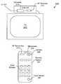
- FIG. 4is a plan view of a remote control according to an embodiment of the invention.
- FIG. 5is a schematic block diagram of an interactive television system according to an embodiment of the invention.
- FIG. 6is a schematic block diagram of a set top box according to an embodiment of the invention.
- FIG. 7is a plan view of a remote control according to an embodiment of the invention.
- FIG. 8is a flowchart of a method for video capture and communication according to an embodiment of the invention.
- Embodiments of a remote control device for video and audio capture and communicationare described herein.
- numerous specific detailsare provided, such as examples of programming, user selections, transactions, etc., to provide a thorough understanding of embodiments of the invention.
- One skilled in the relevant artwill recognize, however, that the invention can be practiced without one or more of the specific details, or with other methods, components, materials, etc.
- well-known structures, materials, or operationsare not shown or described in detail to avoid obscuring aspects of the invention.
- the network 100includes a plurality of set top boxes 102 (hereinafter STB 102 ) or other client terminals located, for instance, at customer homes.
- STB 102is consumer electronics device that serves as a gateway between a customer's television and a broadband communication network, such as a cable network.
- an STB 102is typically located on top of, or in close proximity to, a customer's television.
- an STB 102receives encoded video/audio signals (including television signals) from the network 100 and decodes the same for display on the television. Additionally, an STB 102 receives commands from a user (typically via a remote control) and transmits such commands back to the network 100 .
- each STB 102is connected to a headend 104 .
- a headend 104is a centrally-located facility where cable TV (CATV) channels are received from a local CATV satellite downlink and packaged together for transmission to customer homes.
- CATVcable TV
- the headend 104also functions as a Central Office (CO) in the telephone industry, routing video and audio streams and other data to and from the various STBs 102 serviced thereby.
- COCentral Office
- Headends 104may be coupled directly to one another or through a network center 106 . In some cases, headends 104 may be connected via a separate network, one particular example of which is Internet 108 . Of course, the illustrated network topology is provided for example purposes only, and other network topologies may be used within the scope of the invention.
- an STB 102may transmit video and audio streams to one or more other STBs 102 connected to the network 100 .
- the communication path for the transmissionmay involve one or more headends 104 , network centers 106 , and/or the Internet 108 .
- a first STB 102may send a video transmission upstream to a first headend 104 , then to a second headend 104 , and finally downstream to a second STB 102 .
- the transmissionmay use various standard protocols, such as MPEG or video over IP (Internet Protocol).
- the first and second headends 104may be one and the same if the STBs 102 are served by the same headend 104 .
- the transmission between headends 104may occur (i) via a direct peer-to-peer connection between headends 104 , (ii) upstream from the first headend 104 to a network center 106 and then downstream to the second headend 104 , or (iii) via the Internet 108 .
- each STB 102may be identified by a unique number, code or address, such as an IP (Internet Protocol) address.
- IPInternet Protocol
- a user of one STB 102may indicate an STB 102 to receive an audio or video transmission by specifying the corresponding address.
- the network 100then routes the transmission to its destination using conventional techniques.
- the television system 200preferably includes a television 202 , which is configured to receive and display standard analog or digital television signals or high-definition television (HDTV) signals.
- the television system 200also includes a STB 102 , as discussed above, for sending and receiving audio/video information (including television signals) or other data to and from the network 100 .
- the functionality of the STB 102is integrated into an advanced version of the television 202 .
- a remote control 204is provided for convenient remote operation of the STB 102 and the television 202 .
- the remote control 204may communicate with the STB 102 and television 202 using conventional techniques to adjust, for example, the volume of the television, the displayed channel, and the like.
- the remote control 204includes a camera 208 , such as a color (or monochromatic) digital video camera.
- the cameraincludes a progressive scan CCD (charged coupled device) array to deliver digital video up to 320 ⁇ 240 pixels in 24 bit color.
- CCDcharge coupled device
- the resolution and levels of color of the cameramay also be adjustable or selectable by the viewer.
- a zoom functionmay be provided for the camera 208 .
- the zoom functionmay be lens based or preferably digitally based, e.g., a “digital zoom.”
- the cameramay be provided with automatic white balance and automatic exposure features to adjust for lighting and scene content. Of course, such automatic features may be turned off by the user.
- the frame rate of the video capturemay be 30 frames per second (NTSC, VHS, MPEG), 25 frames per second (PAL), 24 frames per second (motion picture), or other rates.
- NTSCframes per second
- VHSvideo conferencing
- MPEGframes per second
- PALframes per second
- motion picturemotion picture
- a frame rate of 8 frames per secondprovides a somewhat jerky video.
- video conferencing applications using the present inventionis performed at a frame rate of at least 10 frames per second for smoother motion.
- the MPEG-4 protocolmay be used for video conferencing applications using the present invention.
- the cameramay be used to capture not only video, but also still-pictures.
- Such still-picturesmay be stored in JPEG, BMP, TIFF, or other formats in a digital storage device in the STB 102 .
- the remote control 204itself may include a digital storage device to store such still-pictures.
- the resolution of the camera when used to capture still-picturesmay be greater than the resolution when used to capture video.
- the camerais preferably disposed on a surface of the remote control 204 to provide a generally unobstructed view for the camera 208 .
- the cameramay be disposed on the same surface as the majority of the buttons, or it may be disposed on a surface perpendicular to that surface.
- the camera 208is capable of capturing a series of images in real time and converting the same into analog or digital video signals.
- the camera 208is in electrical communication with a specifically-designated button, such as a camera (“cam”) button 206 , which toggles operation of the camera 208 in one implementation.
- the remote control 204may further include additional buttons to control various features of the STB 102 and the television 202 .
- the term “button”includes other types of controls, such as switches and the like.
- more than one button or controlmay be provided to activate and deactivate the camera 208 .
- the remote control 204also includes a microphone 209 for receiving sound waves and converting the same into analog or digital audio signals.
- the microphone 209may be further in communication with the “cam” button 206 to toggle the operation thereof.
- the microphone 209may be enabled through a separate button on the remote control 204 .
- the remote control 204further includes a radio frequency (RF) transmitter 210 .
- the transmitter 210may be configured to transmit using infrared (IR), microwave, VHF, UHF, or other frequencies along the electromagnetic spectrum.
- the transmitter 210is in electrical communication with the camera 208 to receive video information captured by the camera 208 .
- the transmitter 210may further be in electrical communication with the microphone 209 to receive audio information.
- the transmitter 210preferably modulates the video and/or audio information with a carrier frequency to enable transmission of the information to the STB 102 using techniques well known in the art.
- the transmitter 210may operate according to the IEEE 802.11a or 802.11b Wireless Networking standards, the “Bluetooth” standard, or according to other standard or proprietary wireless techniques. Modulation techniques may include spread spectrum, frequency shift keying, multiple carrier, or other techniques known in the art.
- the transmitter 210may include various additional components not specifically illustrated but well known in the art.
- the transmitter 210may include a source encoder to reduce the amount of bandwidth required, a channel encoder to modulate the video and/or audio information with a carrier wave, and a directional or non-directional transmission antenna.
- the transmitter 210may further include an amplifier to increase the transmission signal strength to an appropriate power level.
- the transmitter 210comprises an integrated RF antenna (linear or otherwise configured) etched onto the main printed circuit board of the remote 204 . Integration of the antenna with the remote control's circuit board provides for compactness and efficiency in manufacture.
- the transmitter 210is a high-bandwidth transmitter capable of sending the video/audio information to the STB 102 in real time.
- the transmitter 210may use wideband frequency modulation over a frequency band to provide a one-way video/audio link from the remote control 204 to the STB 102 .
- frequency bandmay be within the 890-960 MHz range (GSM), 1990-2110 MHz range or 2400-2500 MHz range or other frequency ranges as approved by FCC regulations.
- GSM890-960 MHz range
- the one-way video/audio link between remote control 204 and STB 102also provides for efficiency in manufacture, as a two-way video/audio link is not required in accordance with this embodiment.
- the transmitter 210utilizes a frequency division multiplexing (FDM) technique in order to transmit several streams of data simultaneously. These streams may be reassembled at the STB 102 to derive the encoded video/audio information.
- FDMfrequency division multiplexing
- Various other techniques for providing a high bandwidth in multimedia transmissionsmay also be used within the scope of the invention.
- the transmitter 210is configured to broadcast digital signals.
- the transmitter 210may include an analog-to-digital converter (ADC) to convert analog video/audio signals from an analog camera system into digital information.
- ADCanalog-to-digital converter
- the present inventioncontemplates the use of analog or digital or both types of transmissions from the remote control 204 .
- the remote control 204is also in electrical communication with a processor (not shown) that senses a user's operation of the buttons of the remote control 204 and generates appropriate command signals for transmission to the STB 102 and television 202 in order to control the operation of the same.
- a processornot shown
- the STB 102includes an RF receiver 212 for receiving transmissions from the transmitter 210 in the remote control 204 .
- a receiver 212may include an antenna integrated into a printed circuit board (either a main board or a card coupled to a main board) within the STB 102 .
- the receiver 202may also demodulate video/audio information from the modulated band transmitted by the remote control 204 .
- the receiver 212may be configured to receive IR, microwave, VHF, UHF, or other frequencies.
- the receiver 212demodulates the video/audio information contained within a carrier frequency of the transmission.
- the receiver 212may further include components not specifically illustrated but well known in the art.
- the receiver 212may include an antenna for receiving the transmission, an amplifier for increasing the strength of the received signal, and a decoder for separating and demodulating the video and/or audio information from the carrier signal.
- the receiver 212is in electrical communication with a converter 214 , which converts the video and/or audio information into a digital video and/or audio stream compatible for transmission over the network 100 .
- the conversion processmay include compressing the information to improve transmission speed.
- the converter 214is in electrical communication with a headend 104 in order to transmit the network-compatible video/audio stream to one or more other STBs 102 in the network 100 .
- the converter 214is further configured to receive network-compatible video/audio streams from the network 100 and transform the same into display-compatible video/audio signals for display/playback on the television 202 .
- the transmission from the STB 102 to the network 100must be made to be compatible with upstream transmission in the network 100 .
- one or more frequency bands(for example from 5 to 30 MHz) may be reserved for upstream transmission.
- Digital modulationfor example, quadrature amplitude modulation or vestigial sideband modulation
- Various protocolssuch as MPEG or video over IP, may be used to embed the video/audio stream in the digital signals.
- Upstream transmissionwill be accomplished differently for different networks 100 .
- Alternative ways to accomplish upstream transmissioninclude an analog telephone line, ISDN, DSL, or other techniques.
- the STB 102may include a storage interface 302 , which provides access to a digital storage device 304 , such as a hard disk drive or the like.
- the storage interface 302receives video/audio information from the receiver 212 and delivers the same to the digital storage device 304 for storage.
- the video/audio informationmay be stored in an MPEG format or other encoded file formats.
- the video/audio informationmay be converted by the converter 214 into a network-compatible video/audio stream before being stored in the storage device 304 .
- the converter 214includes conventional interface circuitry for communicating with the network 100 .
- a separate network interface(not shown) may be provided, such as a cable modem or the like.
- a cable modemmay operate in accordance with the DOCSIS or DAVIC standards.
- the STB 102may further include a random access memory (RAM) 306 configured to store data for temporary use.
- a read-only memory (ROM) 308may be provided for storing more permanent data, such as fixed code and configuration information.
- the ROM 308may be used to store an operating system for the STB 102 , such as Windows CE® or Linux®.
- the STB 102preferably includes a controller 310 that is in communication with the receiver 212 , the converter 214 , the storage interface 302 , the RAM 306 , the ROM 308 , and the converter 214 .
- the controller 310may be coupled to the other components of the STB 102 via a bus 312 .
- the controller 310may be embodied as a microcontroller, a microprocessor, a digital signal processor (DSP) or other device known in the art.
- the controller 310manages the operation of the STB 102 , including, for example, the conversion of the encoded video/audio information, the storage of the video/audio information, the transmission and reception of video/audio information from the network 100 , and the like.
- the controller 310may perform these and other operations based on control signals generated by the remote control 204 and transmitted to the receiver 212 .
- the video/audio information received from the remote control 204may be displayed directly on the television 202 coupled to the STB 102 .
- the video/audio informationmay also be converted, compressed and transmitted across the network 100 to one or more other STBs 102 where it is displayed on corresponding televisions 202 .
- a usermay select which STB(s) 102 will receive a video/audio transmission by entering one or more addresses of the receiving STB(s) 102 using the remote control 204 .
- the address of an STB 102uniquely identifies the STB 102 within the network 100 and is used by the headends 104 , network centers 106 , and/or the Internet 108 to route a network-compatible video/audio stream to the appropriate STB 102 using conventional techniques.
- an STB 102may simultaneously send and receive multiple video/audio streams. In this manner, video conferencing of networked interactive television systems 200 is enabled.
- FIG. 4provides an expanded view of the remote control 204 , including the camera 208 , the microphone 209 , the transmitter 210 , and the “cam” button 206 .
- FIG. 4illustrates an activity indicator 402 , which illuminates or otherwise signals the user when the camera 208 and/or microphone 209 is active.
- the activity indicator 402may be embodied as an LED (light-emitting diode) or other suitable indicator.
- the remote control 204may include a number of other buttons or controls, such as an “accept” button 406 , a “reject” button 408 , and a “switch” button 410 , the functions of which are described below.
- the various components of the remote control 204may be positioned in different locations for ergonomics and ease-of-use.
- the camera 208 , “cam” button 206 , and activity indicator 402may be disposed at any convenient and ergonomic location within the remote control 204 .
- FIG. 5there is shown an alternative interactive television system 500 according to an embodiment of the invention.
- the television system 500differs primarily from the television system 200 of FIG. 2 in that the camera 208 and microphone 209 are disposed within a STB 502 rather than a remote control 504 .
- the remote control 504includes an infrared (IR) transmitter 506 for sending control signals to an IR receiver 508 within the STB 502 and/or the television 202 .
- the transmittermay use RF, VHF, UHF, microwave, or other frequencies.
- the remote control 504also includes a “cam” button 206 for enabling remote operation of the camera 208 and/or the microphone 209 disposed within the STB 502 .
- FIG. 6there is shown an expanded block diagram of the STB 502 .
- the converter 214 , the storage interface 302 , the digital storage device 304 , the RAM 306 , the ROM 308 , and the controller 310function as previously described with reference to FIG. 3 .
- the STB 502includes a camera 208 and a microphone 209 , which are depicted as being in communication with the bus 312 .
- the STB 502is depicted as including an activity indicator 402 for visually indicating to a user when the camera 208 is active.
- FIG. 7provides an expanded view of the remote control 504 , including the IR transmitter 506 , the “cam” button 206 , the “accept” button 406 and the “reject” button 408 .
- the remote control 504may also include a separate activity indicator 402 in addition to the indicator 504 in the STB 502 .
- Those skilled in the artwill recognize that the various components of the remote control 504 may be positioned in different locations for convenience and ergonomics.
- the remote control 504 and the STB 502may both be configured with a camera 208 and/or a microphone 209 . This would allow a user to select between a camera 208 disposed locally on the remote control 504 and a camera 208 disposed remotely on the STB 102 . Thus, a user may conveniently switch between a stationary camera 208 at a fixed distance or a remote-mounted camera 208 that is highly mobile, depending on the subject to be viewed. In one embodiment, the “switch” button 410 of FIG. 4 may be used for this purpose.
- FIG. 8is a flowchart of a method 800 for video and audio capture and communication according to an embodiment of the invention.
- the method 800begins when a user of a first STB 102 selects 802 a second STB 102 (or set of STBs 102 ) in the network 100 to receive a video/audio transmission. The selection may be performed by entering an identification of the second STB 102 or a user thereof by means the remote control 204 . If a user's name is specified, for example, the first STB 102 may access a name server or directory (not shown) to retrieve a corresponding address of the second STB 102 . In one embodiment, the first STB 102 may contain a local directory of addresses to which the user frequently sends video/audio transmissions.
- the first STB 102Once the first STB 102 has a valid address, it sends a request across the network 100 to the second STB 102 .
- the precise format of the requestis not crucial to the invention, but the request should indicate to the second STB 102 that the user of the first STB 102 desires to send a video/audio transmission.
- the second STB 102In response to the request, the second STB 102 generates a notification, such as a text message or icon, for display on the corresponding television 202 to notify the user of the second STB 102 of the video/audio transmission.
- the notificationmay take the form of an audio signal that is played on a speaker (not shown) in the STB 102 or the television 202 .
- the first STB 102may wait until a timeout period has expired, after which it notifies the user that the audio/video transmission cannot be sent. Likewise, if the user of the second STB 102 does not respond, or refuses to receive the transmission (by means of the “reject” button 408 of FIG. 4, for example) a not-available signal may be returned to the first STB 102 .
- the user of the second STB 102wishes to receive the video/audio transmission, she may press a suitable button the remote control 204 , such as the “accept” button 406 of FIG. 4, which results in an acceptance signal being returned to the first STB 102 .
- the first STB 102generates, in response to receiving the acceptance signal, a video or audio acceptance message to notify the user that permission for the video/audio transmission has been granted.
- the first and second STBs 102may then initiate 804 a handshake procedure to establish a communication protocol.
- a handshake proceduremay have some similarity with handshake procedures performed between facsimile (fax) machines.
- the STBs 102may negotiate a new protocol or reaffirm an existing protocol for video/audio communication.
- the appropriate protocolmay need to be determined because the two STBs have different video/audio conferencing capabilities.
- the second STBmay be capable of video conferencing at a lower resolution (or frame rate), so the communication protocol would be established as is suitable to this lower resolution (or frame rate).
- the communication protocol usedmay also depend on the bandwidth and/or reliability of the connection between the two set top boxes.
- an active communication linkis established between the first and second STBs 102 across the network 100 .
- the first userthen activates 806 the camera 208 and/or microphone 209 by pressing, for example, the “cam” button 206 .
- the remote control 204 and/or STB 102indicates 808 activation of the camera 208 by a visual mechanism, such as an activity indicator 402 (e.g., LED). Thereafter, the camera 208 and/or microphone 209 captures 810 a video and/or audio signal (which is transmitted to the STB 102 in the case of the remote control 204 of FIG. 2 ).
- the converter 214 within the STB 102then transforms 812 the captured video/audio signal into a network-compatible video/audio stream for transmission over the network 100 . Thereafter, the network-compatible video/audio stream is transmitted 814 upstream to the network 100 .
- the communication path for the transmissionmay involve one or more headends 104 , network centers 106 , and/or the Internet 108 , using conventional routing techniques.
- the network-compatible video/audio streamis then transmitted 816 downstream from the network 100 to the second STB 102 . Thereafter, the network-compatible video/audio stream is transformed 818 into a display-compatible video/audio signal for display 820 on the television 202 .
- the second STB 102may transmit video/audio information to the first STB 102 .
- multiple video/audio streamsmay be received and transmitted simultaneously by a STB 102 .
- Multiple video streams received by a STB 102may be displayed on a television 202 at the same time using picture-in-picture (PIP) techniques.
- PIPpicture-in-picture
- multiple audio streamsmay be mixed for playback on the television 202 .
- video conferencing between two or more users of networked interactive television systems 200is enabled.
- the first STB 102may transmit a video/audio stream to the second STB 102 without waiting for an acceptance signal.
- the second STB 102may record all incoming transmissions in the digital storage device 304 . Thereafter, a user of the second STB 102 may review the stored video/audio streams and select which stream, if any, to display at a convenient time.
- the first STB 102may be preconfigured to transmit video/audio information to a second STB 102 , which has previously granted permission to receive the transmission. Accordingly, a user of the first STB 102 may simply press the “cam” button 206 to immediately capture video/audio information and transmit the same to the second STB 102 for immediate display.
- the video/audio conferencingmay occur between the first STB 102 and a client terminal more generically (not just a second STB 102 ).
- the client terminalmay comprise a personal computer or other device with a connection to the Internet 108 .
- Such other devicesmay include Internet appliances, personal digital assistants, Internet-enabled cell phones, and the like. These devices are likely to have varying videoconferencing capabilities, so a handshaking procedure as described above is likely to be quite useful in determining a proper communication protocol.
- the present inventionoffers numerous advantages not available in the prior art.
- a usermay easily capture video images of events that would be difficult or impossible to capture with conventional “webcam” devices.
- the remote control 204is not limited by a physical cable, a user has the flexibility of carrying the remote control 204 to any desired location.
- the camera 208is integrated with the STB 102 , it is likely that a user will be able to capture events of primary interest, since televisions 202 their associated STBs 102 are normally located in areas of high use, such as family rooms and the like.
Landscapes
- Engineering & Computer Science (AREA)
- Signal Processing (AREA)
- Multimedia (AREA)
- Computer Networks & Wireless Communication (AREA)
- Human Computer Interaction (AREA)
- General Engineering & Computer Science (AREA)
- Power Engineering (AREA)
- Two-Way Televisions, Distribution Of Moving Picture Or The Like (AREA)
- Studio Devices (AREA)
Abstract
Description
Claims (12)
Priority Applications (3)
| Application Number | Priority Date | Filing Date | Title |
|---|---|---|---|
| US09/698,297US6489986B1 (en) | 2000-09-29 | 2000-10-27 | Remote control device for video and audio capture and communication |
| AU2001255535AAU2001255535A1 (en) | 2000-09-29 | 2001-04-19 | Remote control device for video and audio capture and communication |
| PCT/US2001/012894WO2002030116A1 (en) | 2000-09-29 | 2001-04-19 | Remote control device for video and audio capture and communication |
Applications Claiming Priority (2)
| Application Number | Priority Date | Filing Date | Title |
|---|---|---|---|
| US23701300P | 2000-09-29 | 2000-09-29 | |
| US09/698,297US6489986B1 (en) | 2000-09-29 | 2000-10-27 | Remote control device for video and audio capture and communication |
Publications (1)
| Publication Number | Publication Date |
|---|---|
| US6489986B1true US6489986B1 (en) | 2002-12-03 |
Family
ID=26930316
Family Applications (1)
| Application Number | Title | Priority Date | Filing Date |
|---|---|---|---|
| US09/698,297Expired - LifetimeUS6489986B1 (en) | 2000-09-29 | 2000-10-27 | Remote control device for video and audio capture and communication |
Country Status (3)
| Country | Link |
|---|---|
| US (1) | US6489986B1 (en) |
| AU (1) | AU2001255535A1 (en) |
| WO (1) | WO2002030116A1 (en) |
Cited By (63)
| Publication number | Priority date | Publication date | Assignee | Title |
|---|---|---|---|---|
| US20020143851A1 (en)* | 2000-12-22 | 2002-10-03 | Schwartz Richard L. | Method and system for facilitating mediated communication |
| US20020141388A1 (en)* | 2000-12-22 | 2002-10-03 | Schwartz Richard L. | Method and system for facilitating mediated communication |
| US20020140726A1 (en)* | 2000-12-22 | 2002-10-03 | Schwartz Richard L. | Method and system for facilitating mediated communication |
| US20020147811A1 (en)* | 2000-12-22 | 2002-10-10 | Schwartz Richard L. | Method and system for facilitating mediated communication |
| US20030005126A1 (en)* | 2001-05-25 | 2003-01-02 | Solomio Corp. | Method and system for facilitating interactive communication |
| US20030039339A1 (en)* | 2000-12-22 | 2003-02-27 | Uwe Luehrig | Method and system for facilitating mediated communication |
| US20030123634A1 (en)* | 2000-12-22 | 2003-07-03 | Wei-Meng Chee | Method and system for facilitating mediated communication |
| US20030222990A1 (en)* | 2002-05-29 | 2003-12-04 | John Driska | Video camera for transmitting video, audio and control signals to a remote recording device |
| US20040095316A1 (en)* | 2002-11-19 | 2004-05-20 | Canon Kabushiki Kaisha | Display apparatus and remote control control apparatus |
| US20040114036A1 (en)* | 2002-12-11 | 2004-06-17 | Jeyhan Karaoguz | Personal streaming and broadcast channels in a media exchange network |
| US20040117813A1 (en)* | 2002-12-11 | 2004-06-17 | Jeyhan Karaoguz | Third party media channel access in a media exchange network |
| US20040117842A1 (en)* | 2002-12-11 | 2004-06-17 | Jeyhan Karaoguz | Method and system for personal channel programming in a media exchange network |
| US20040150713A1 (en)* | 2003-01-31 | 2004-08-05 | Cheng Y. P. | Cordless IP video phone |
| US20040207719A1 (en)* | 2003-04-15 | 2004-10-21 | Tervo Timo P. | Method and apparatus for exploiting video streaming services of mobile terminals via proximity connections |
| US20040257432A1 (en)* | 2003-06-20 | 2004-12-23 | Apple Computer, Inc. | Video conferencing system having focus control |
| US20040257431A1 (en)* | 2003-06-20 | 2004-12-23 | Apple Computer, Inc., A California Corporation | Video conferencing apparatus and method |
| US20050057699A1 (en)* | 2003-09-16 | 2005-03-17 | Bowser Todd S. | Remote master control |
| US20050073574A1 (en)* | 2003-10-01 | 2005-04-07 | Krisbergh Hal M. | Videophone system and method |
| US6950503B2 (en) | 2000-12-22 | 2005-09-27 | Solomio Corporation | Method and system for facilitating mediated communication |
| US20060001737A1 (en)* | 2004-07-01 | 2006-01-05 | Dawson Thomas P | Video conference arrangement |
| US20060259942A1 (en)* | 2005-05-13 | 2006-11-16 | Microsoft Corporation | Phone-to-monitor connection device |
| US20070013801A1 (en)* | 2004-03-24 | 2007-01-18 | Sezan Muhammed I | Methods and Systems for A/V Input Device to Display Networking |
| US20070090277A1 (en)* | 2004-10-22 | 2007-04-26 | Gary Palmer | Ruggedized digital low-light viewing device |
| US20080042868A1 (en)* | 2006-04-25 | 2008-02-21 | Lg Electronics Inc. | Remote controlling system for electric device |
| US20080104655A1 (en)* | 2006-10-31 | 2008-05-01 | General Instrument Corporation | Digital Video Recorder Having a Pause Feature Displaying the First Frame of a Program |
| US20080139193A1 (en)* | 2006-12-08 | 2008-06-12 | Verizon Data Services | Method, computer program product, and apparatus for providing communications with at least one media provider |
| US20080151126A1 (en)* | 2006-12-20 | 2008-06-26 | Amtran Technology Co., Ltd. | Remote control having audio-visual function |
| US20090185617A1 (en)* | 2008-01-17 | 2009-07-23 | Houghton Ricky A | Method and system for adapting use of a radio link between a remotely controlled device and an operator control unit |
| US7570485B2 (en) | 2004-03-12 | 2009-08-04 | Apple Inc. | Camera latch |
| US20090251559A1 (en)* | 2002-11-20 | 2009-10-08 | Koninklijke Philips Electronics N.V. | User interface system based on pointing device |
| US20090282098A1 (en)* | 2002-12-11 | 2009-11-12 | Jeyhan Karaoguz | Personal Inter-Home Media Exchange Network |
| US20100088730A1 (en)* | 2005-02-07 | 2010-04-08 | Oklejas Robert A | Hybrid audio/video entertainment system |
| US20100085432A1 (en)* | 1999-11-15 | 2010-04-08 | Xenonics, Inc. | Portable device for viewing and imaging |
| US20100333163A1 (en)* | 2009-06-25 | 2010-12-30 | Echostar Technologies L.L.C. | Voice enabled media presentation systems and methods |
| US8051447B2 (en) | 2007-12-19 | 2011-11-01 | Verizon Patent And Licensing Inc. | Condensed program guide for media content access systems and methods |
| US8069461B2 (en) | 2006-03-30 | 2011-11-29 | Verizon Services Corp. | On-screen program guide with interactive programming recommendations |
| US8103965B2 (en) | 2007-06-28 | 2012-01-24 | Verizon Patent And Licensing Inc. | Media content recording and healing statuses |
| US8418217B2 (en) | 2006-09-06 | 2013-04-09 | Verizon Patent And Licensing Inc. | Systems and methods for accessing media content |
| US8443038B2 (en) | 2004-06-04 | 2013-05-14 | Apple Inc. | Network media device |
| US8464295B2 (en) | 2006-10-03 | 2013-06-11 | Verizon Patent And Licensing Inc. | Interactive search graphical user interface systems and methods |
| US8510780B2 (en) | 2006-12-21 | 2013-08-13 | Verizon Patent And Licensing Inc. | Program guide navigation tools for media content access systems and methods |
| US8516257B2 (en) | 2002-12-11 | 2013-08-20 | Broadcom Corporation | Secure media peripheral association in a media exchange network |
| US8566874B2 (en) | 2006-10-03 | 2013-10-22 | Verizon Patent And Licensing Inc. | Control tools for media content access systems and methods |
| US20130298028A1 (en)* | 2011-04-19 | 2013-11-07 | Shahar Porat | Multifunctional input device |
| US8661489B2 (en) | 2002-12-11 | 2014-02-25 | Broadcom Corporation | Media processing system supporting adaptive digital media parameters based on end-user viewing capabilities |
| US8681822B2 (en) | 2004-06-04 | 2014-03-25 | Apple Inc. | System and method for synchronizing media presentation at multiple recipients |
| US8726159B2 (en) | 2007-01-05 | 2014-05-13 | Verizon Patent And Licensing Inc. | Content level navigation systems and methods |
| WO2014209221A1 (en)* | 2012-06-26 | 2014-12-31 | Vodoke Asia Pacific Limited | A remote controller |
| US9131079B2 (en) | 2005-02-07 | 2015-09-08 | Robert A. Oklejas | System and method for providing a television network customized for an end user |
| CN104967223A (en)* | 2015-06-25 | 2015-10-07 | 深圳市九洲电器有限公司 | Set top box being capable of storage and charging |
| US9305590B2 (en) | 2007-10-16 | 2016-04-05 | Seagate Technology Llc | Prevent data storage device circuitry swap |
| US9679602B2 (en) | 2006-06-14 | 2017-06-13 | Seagate Technology Llc | Disc drive circuitry swap |
| US20170272791A1 (en)* | 2002-09-17 | 2017-09-21 | Lightside Technologies LLC | High-Quality, Reduced Data Rate Streaming Video Production and Monitoring System |
| US9894505B2 (en) | 2004-06-04 | 2018-02-13 | Apple Inc. | Networked media station |
| CN102842213B (en)* | 2011-06-24 | 2018-05-22 | 索尼公司 | Remote control terminal and information processing device |
| US10219035B2 (en) | 2005-02-07 | 2019-02-26 | Robert A. Oklejas | System and method for providing a television network customized for an end user |
| US10614857B2 (en) | 2018-07-02 | 2020-04-07 | Apple Inc. | Calibrating media playback channels for synchronized presentation |
| US10783929B2 (en) | 2018-03-30 | 2020-09-22 | Apple Inc. | Managing playback groups |
| US10972536B2 (en) | 2004-06-04 | 2021-04-06 | Apple Inc. | System and method for synchronizing media presentation at multiple recipients |
| US10993274B2 (en) | 2018-03-30 | 2021-04-27 | Apple Inc. | Pairing devices by proxy |
| US11297369B2 (en) | 2018-03-30 | 2022-04-05 | Apple Inc. | Remotely controlling playback devices |
| US11531700B2 (en)* | 2018-08-03 | 2022-12-20 | Gracenote, Inc. | Tagging an image with audio-related metadata |
| US11910130B2 (en)* | 2021-03-02 | 2024-02-20 | Carnegie Mellon University | Media control device and system |
Families Citing this family (10)
| Publication number | Priority date | Publication date | Assignee | Title |
|---|---|---|---|---|
| US7475243B2 (en) | 2002-12-11 | 2009-01-06 | Broadcom Corporation | Preventing a non-head end based service provider from sending media to a media processing system |
| US7450501B2 (en) | 2002-12-11 | 2008-11-11 | Broadcom Corporation | Media processing system based on satellite set top box platform with telephony downstream and upstream data paths |
| US20050068307A1 (en)* | 2003-09-30 | 2005-03-31 | Microsoft Corporation | System, method and apparatus for a media computing device remote control |
| GB2463108B (en) | 2008-09-05 | 2012-08-29 | Skype | Communication system and method |
| GB2463104A (en) | 2008-09-05 | 2010-03-10 | Skype Ltd | Thumbnail selection of telephone contact using zooming |
| GB2463103A (en)* | 2008-09-05 | 2010-03-10 | Skype Ltd | Video telephone call using a television receiver |
| GB2463105A (en)* | 2008-09-05 | 2010-03-10 | Skype Ltd | Viewer activity dependent video telephone call ringing |
| GB2463107A (en) | 2008-09-05 | 2010-03-10 | Skype Ltd | A remote control unit of a media device for placing/receiving calls, comprising activating one of the two wireless transceivers when needed. |
| GB2463110B (en) | 2008-09-05 | 2013-01-16 | Skype | Communication system and method |
| GB2463124B (en) | 2008-09-05 | 2012-06-20 | Skype Ltd | A peripheral device for communication over a communications sytem |
Citations (18)
| Publication number | Priority date | Publication date | Assignee | Title |
|---|---|---|---|---|
| JPH06351016A (en)* | 1993-06-07 | 1994-12-22 | Nippon Telegr & Teleph Corp <Ntt> | Method and device for remote control of video conference device |
| US5585850A (en) | 1994-10-31 | 1996-12-17 | Schwaller; John | Adaptive distribution system for transmitting wideband video data over narrowband multichannel wireless communication system |
| US5666159A (en) | 1995-04-24 | 1997-09-09 | Eastman Kodak Company | Electronic camera system with programmable transmission capability |
| US5748238A (en) | 1992-03-12 | 1998-05-05 | Hitachi, Ltd. | Video camera |
| JPH10336492A (en)* | 1997-05-29 | 1998-12-18 | Seiko Epson Corp | Digital camera |
| JPH1169463A (en)* | 1997-08-18 | 1999-03-09 | Sony Corp | Remote controller |
| US5910815A (en)* | 1994-09-13 | 1999-06-08 | U.S. Philips Corporation | Telephone set |
| JPH11215420A (en) | 1998-01-26 | 1999-08-06 | Sony Corp | Remote controller |
| JPH11234639A (en)* | 1998-02-17 | 1999-08-27 | Matsushita Electric Ind Co Ltd | Videophone equipment |
| US5995155A (en)* | 1995-07-17 | 1999-11-30 | Gateway 2000, Inc. | Database navigation system for a home entertainment system |
| US5999207A (en)* | 1997-05-16 | 1999-12-07 | Scientific-Atlanta, Inc. | Method and apparatus for implementing a user interface for a videophone in a cable television network |
| JPH11355706A (en) | 1998-03-24 | 1999-12-24 | Canon Inc | Digital camera image management system |
| JP2000151871A (en) | 1998-11-10 | 2000-05-30 | Precision:Kk | Portable image communication terminal |
| JP2000156869A (en)* | 1998-11-19 | 2000-06-06 | Nikon Corp | Digital camera |
| US6137525A (en) | 1997-02-19 | 2000-10-24 | Lg Electronics Inc. | Personal data communication apparatus |
| US6219109B1 (en) | 1998-01-21 | 2001-04-17 | Evolve Products, Inc. | Remote control with direct TV operation |
| US6256060B1 (en) | 1996-05-17 | 2001-07-03 | Asahi Kogaku Kogyo Kabushiki Kaisha | Still video camera system with remote controller |
| US6281925B1 (en)* | 1998-10-14 | 2001-08-28 | Denso Corporation | Video telephone device having automatic sound level setting along with operation mode switching |
- 2000
- 2000-10-27USUS09/698,297patent/US6489986B1/ennot_activeExpired - Lifetime
- 2001
- 2001-04-19AUAU2001255535Apatent/AU2001255535A1/ennot_activeAbandoned
- 2001-04-19WOPCT/US2001/012894patent/WO2002030116A1/enactiveApplication Filing
Patent Citations (18)
| Publication number | Priority date | Publication date | Assignee | Title |
|---|---|---|---|---|
| US5748238A (en) | 1992-03-12 | 1998-05-05 | Hitachi, Ltd. | Video camera |
| JPH06351016A (en)* | 1993-06-07 | 1994-12-22 | Nippon Telegr & Teleph Corp <Ntt> | Method and device for remote control of video conference device |
| US5910815A (en)* | 1994-09-13 | 1999-06-08 | U.S. Philips Corporation | Telephone set |
| US5585850A (en) | 1994-10-31 | 1996-12-17 | Schwaller; John | Adaptive distribution system for transmitting wideband video data over narrowband multichannel wireless communication system |
| US5666159A (en) | 1995-04-24 | 1997-09-09 | Eastman Kodak Company | Electronic camera system with programmable transmission capability |
| US5995155A (en)* | 1995-07-17 | 1999-11-30 | Gateway 2000, Inc. | Database navigation system for a home entertainment system |
| US6256060B1 (en) | 1996-05-17 | 2001-07-03 | Asahi Kogaku Kogyo Kabushiki Kaisha | Still video camera system with remote controller |
| US6137525A (en) | 1997-02-19 | 2000-10-24 | Lg Electronics Inc. | Personal data communication apparatus |
| US5999207A (en)* | 1997-05-16 | 1999-12-07 | Scientific-Atlanta, Inc. | Method and apparatus for implementing a user interface for a videophone in a cable television network |
| JPH10336492A (en)* | 1997-05-29 | 1998-12-18 | Seiko Epson Corp | Digital camera |
| JPH1169463A (en)* | 1997-08-18 | 1999-03-09 | Sony Corp | Remote controller |
| US6219109B1 (en) | 1998-01-21 | 2001-04-17 | Evolve Products, Inc. | Remote control with direct TV operation |
| JPH11215420A (en) | 1998-01-26 | 1999-08-06 | Sony Corp | Remote controller |
| JPH11234639A (en)* | 1998-02-17 | 1999-08-27 | Matsushita Electric Ind Co Ltd | Videophone equipment |
| JPH11355706A (en) | 1998-03-24 | 1999-12-24 | Canon Inc | Digital camera image management system |
| US6281925B1 (en)* | 1998-10-14 | 2001-08-28 | Denso Corporation | Video telephone device having automatic sound level setting along with operation mode switching |
| JP2000151871A (en) | 1998-11-10 | 2000-05-30 | Precision:Kk | Portable image communication terminal |
| JP2000156869A (en)* | 1998-11-19 | 2000-06-06 | Nikon Corp | Digital camera |
Cited By (125)
| Publication number | Priority date | Publication date | Assignee | Title |
|---|---|---|---|---|
| US20100085432A1 (en)* | 1999-11-15 | 2010-04-08 | Xenonics, Inc. | Portable device for viewing and imaging |
| US6985924B2 (en) | 2000-12-22 | 2006-01-10 | Solomio Corporation | Method and system for facilitating mediated communication |
| US20020143851A1 (en)* | 2000-12-22 | 2002-10-03 | Schwartz Richard L. | Method and system for facilitating mediated communication |
| US20020147811A1 (en)* | 2000-12-22 | 2002-10-10 | Schwartz Richard L. | Method and system for facilitating mediated communication |
| US8144840B2 (en) | 2000-12-22 | 2012-03-27 | Openwave Systems Inc. | Method and system for facilitating mediated communication |
| US20030039339A1 (en)* | 2000-12-22 | 2003-02-27 | Uwe Luehrig | Method and system for facilitating mediated communication |
| US20030123634A1 (en)* | 2000-12-22 | 2003-07-03 | Wei-Meng Chee | Method and system for facilitating mediated communication |
| US20020140726A1 (en)* | 2000-12-22 | 2002-10-03 | Schwartz Richard L. | Method and system for facilitating mediated communication |
| US7197120B2 (en)* | 2000-12-22 | 2007-03-27 | Openwave Systems Inc. | Method and system for facilitating mediated communication |
| US20020141388A1 (en)* | 2000-12-22 | 2002-10-03 | Schwartz Richard L. | Method and system for facilitating mediated communication |
| USRE45926E1 (en) | 2000-12-22 | 2016-03-15 | Unwired Planet, Llc | Method and system for facilitating mediated communication |
| US7209966B2 (en) | 2000-12-22 | 2007-04-24 | Openwave Systems Inc. | Method and system for facilitating mediated communication |
| US7751383B2 (en) | 2000-12-22 | 2010-07-06 | Openwave Systems Inc. | Method and system for facilitating mediated communication |
| US6950503B2 (en) | 2000-12-22 | 2005-09-27 | Solomio Corporation | Method and system for facilitating mediated communication |
| US20030005126A1 (en)* | 2001-05-25 | 2003-01-02 | Solomio Corp. | Method and system for facilitating interactive communication |
| US20030222990A1 (en)* | 2002-05-29 | 2003-12-04 | John Driska | Video camera for transmitting video, audio and control signals to a remote recording device |
| US10945004B2 (en) | 2002-09-17 | 2021-03-09 | Hawk Technology Systems, L.L.C. | High-quality, reduced data rate streaming video production and monitoring system |
| US10499091B2 (en)* | 2002-09-17 | 2019-12-03 | Kinya Washino | High-quality, reduced data rate streaming video production and monitoring system |
| US11395017B2 (en) | 2002-09-17 | 2022-07-19 | Hawk Technology Systems, L.L.C. | High-quality, reduced data rate streaming video production and monitoring system |
| US20170272791A1 (en)* | 2002-09-17 | 2017-09-21 | Lightside Technologies LLC | High-Quality, Reduced Data Rate Streaming Video Production and Monitoring System |
| US7383507B2 (en)* | 2002-11-19 | 2008-06-03 | Canon Kabushiki Kaisha | Display apparatus and remote control apparatus |
| US20040095316A1 (en)* | 2002-11-19 | 2004-05-20 | Canon Kabushiki Kaisha | Display apparatus and remote control control apparatus |
| US20090251559A1 (en)* | 2002-11-20 | 2009-10-08 | Koninklijke Philips Electronics N.V. | User interface system based on pointing device |
| US8971629B2 (en) | 2002-11-20 | 2015-03-03 | Koninklijke Philips N.V. | User interface system based on pointing device |
| US20110187643A1 (en)* | 2002-11-20 | 2011-08-04 | Koninklijke Philips Electronics N.V. | User interface system based on pointing device |
| US8970725B2 (en) | 2002-11-20 | 2015-03-03 | Koninklijke Philips N.V. | User interface system based on pointing device |
| US8537231B2 (en) | 2002-11-20 | 2013-09-17 | Koninklijke Philips N.V. | User interface system based on pointing device |
| US20090282098A1 (en)* | 2002-12-11 | 2009-11-12 | Jeyhan Karaoguz | Personal Inter-Home Media Exchange Network |
| US9357256B2 (en) | 2002-12-11 | 2016-05-31 | Broadcom Corporation | Third party media channel access in a media exchange network |
| US8661489B2 (en) | 2002-12-11 | 2014-02-25 | Broadcom Corporation | Media processing system supporting adaptive digital media parameters based on end-user viewing capabilities |
| US8239512B2 (en)* | 2002-12-11 | 2012-08-07 | Broadcom Corporation | Personal inter-home media exchange network |
| US20110258557A1 (en)* | 2002-12-11 | 2011-10-20 | Jeyhan Karaoguz | Personal streaming and broadcast channels in a media exchange network |
| US20040117842A1 (en)* | 2002-12-11 | 2004-06-17 | Jeyhan Karaoguz | Method and system for personal channel programming in a media exchange network |
| US20040117813A1 (en)* | 2002-12-11 | 2004-06-17 | Jeyhan Karaoguz | Third party media channel access in a media exchange network |
| US20040114036A1 (en)* | 2002-12-11 | 2004-06-17 | Jeyhan Karaoguz | Personal streaming and broadcast channels in a media exchange network |
| US8516257B2 (en) | 2002-12-11 | 2013-08-20 | Broadcom Corporation | Secure media peripheral association in a media exchange network |
| US20040150713A1 (en)* | 2003-01-31 | 2004-08-05 | Cheng Y. P. | Cordless IP video phone |
| WO2004092863A3 (en)* | 2003-04-15 | 2005-01-27 | Nokia Corp | Method and apparatus for exploiting video streaming services of mobile terminals via proximity connections |
| US20040207719A1 (en)* | 2003-04-15 | 2004-10-21 | Tervo Timo P. | Method and apparatus for exploiting video streaming services of mobile terminals via proximity connections |
| US20040257431A1 (en)* | 2003-06-20 | 2004-12-23 | Apple Computer, Inc., A California Corporation | Video conferencing apparatus and method |
| WO2005002193A3 (en)* | 2003-06-20 | 2006-03-09 | Apple Computer | Video conferencing apparatus and method |
| US8179419B2 (en)* | 2003-06-20 | 2012-05-15 | Apple Inc. | Video conferencing apparatus and method |
| US7397495B2 (en)* | 2003-06-20 | 2008-07-08 | Apple Inc. | Video conferencing apparatus and method |
| US7559026B2 (en) | 2003-06-20 | 2009-07-07 | Apple Inc. | Video conferencing system having focus control |
| US20040257432A1 (en)* | 2003-06-20 | 2004-12-23 | Apple Computer, Inc. | Video conferencing system having focus control |
| US20080218583A1 (en)* | 2003-06-20 | 2008-09-11 | Apple Inc. | Video conferencing apparatus and method |
| US20050057699A1 (en)* | 2003-09-16 | 2005-03-17 | Bowser Todd S. | Remote master control |
| US7239338B2 (en)* | 2003-10-01 | 2007-07-03 | Worldgate Service, Inc. | Videophone system and method |
| US20050073574A1 (en)* | 2003-10-01 | 2005-04-07 | Krisbergh Hal M. | Videophone system and method |
| US20110228041A1 (en)* | 2003-10-01 | 2011-09-22 | Krisbergh Hal M | Videophone System and Method |
| US7570485B2 (en) | 2004-03-12 | 2009-08-04 | Apple Inc. | Camera latch |
| US8035481B2 (en) | 2004-03-12 | 2011-10-11 | Apple Inc. | Illuminable latch |
| US8384518B2 (en) | 2004-03-12 | 2013-02-26 | Apple Inc. | Illuminable latch |
| US20090268401A1 (en)* | 2004-03-12 | 2009-10-29 | Apple Inc. | Camera latch |
| US20070013801A1 (en)* | 2004-03-24 | 2007-01-18 | Sezan Muhammed I | Methods and Systems for A/V Input Device to Display Networking |
| US7929021B2 (en) | 2004-03-24 | 2011-04-19 | Sharp Laboratories Of America, Inc. | Methods and systems for A/V input device to display networking |
| US9894505B2 (en) | 2004-06-04 | 2018-02-13 | Apple Inc. | Networked media station |
| US9448683B2 (en) | 2004-06-04 | 2016-09-20 | Apple Inc. | Network media device |
| US10264070B2 (en) | 2004-06-04 | 2019-04-16 | Apple Inc. | System and method for synchronizing media presentation at multiple recipients |
| US8681822B2 (en) | 2004-06-04 | 2014-03-25 | Apple Inc. | System and method for synchronizing media presentation at multiple recipients |
| US10200430B2 (en) | 2004-06-04 | 2019-02-05 | Apple Inc. | Network media device |
| US8443038B2 (en) | 2004-06-04 | 2013-05-14 | Apple Inc. | Network media device |
| US9729630B2 (en) | 2004-06-04 | 2017-08-08 | Apple Inc. | System and method for synchronizing media presentation at multiple recipients |
| US9876830B2 (en) | 2004-06-04 | 2018-01-23 | Apple Inc. | Network media device |
| US10986148B2 (en) | 2004-06-04 | 2021-04-20 | Apple Inc. | Network media device |
| US10972536B2 (en) | 2004-06-04 | 2021-04-06 | Apple Inc. | System and method for synchronizing media presentation at multiple recipients |
| US20060001737A1 (en)* | 2004-07-01 | 2006-01-05 | Dawson Thomas P | Video conference arrangement |
| US20070090277A1 (en)* | 2004-10-22 | 2007-04-26 | Gary Palmer | Ruggedized digital low-light viewing device |
| US7420153B2 (en)* | 2004-10-22 | 2008-09-02 | Xenonics, Inc. | Low-light viewing device having camera assembly with image signal containing visible light and infrared energy components and method for controlling same |
| US20100088730A1 (en)* | 2005-02-07 | 2010-04-08 | Oklejas Robert A | Hybrid audio/video entertainment system |
| US8978087B2 (en) | 2005-02-07 | 2015-03-10 | Robert A. Oklejas | Hybrid audio/video entertainment system |
| US8151315B2 (en) | 2005-02-07 | 2012-04-03 | Oklejas Robert A | Hybrid audio/video entertainment system |
| US9420321B2 (en) | 2005-02-07 | 2016-08-16 | Robert A. Oklejas | System and method for providing a television network customized for an end user |
| US10219035B2 (en) | 2005-02-07 | 2019-02-26 | Robert A. Oklejas | System and method for providing a television network customized for an end user |
| US9131079B2 (en) | 2005-02-07 | 2015-09-08 | Robert A. Oklejas | System and method for providing a television network customized for an end user |
| US7835505B2 (en)* | 2005-05-13 | 2010-11-16 | Microsoft Corporation | Phone-to-monitor connection device |
| US20060259942A1 (en)* | 2005-05-13 | 2006-11-16 | Microsoft Corporation | Phone-to-monitor connection device |
| US8677415B2 (en) | 2006-03-30 | 2014-03-18 | Verizon Services Corp. | On-screen program guide with interactive programming recommendations |
| US8069461B2 (en) | 2006-03-30 | 2011-11-29 | Verizon Services Corp. | On-screen program guide with interactive programming recommendations |
| US9084029B2 (en) | 2006-03-30 | 2015-07-14 | Verizon Patent And Licensing Inc. | On-screen program guide with interactive programming recommendations |
| US20080042868A1 (en)* | 2006-04-25 | 2008-02-21 | Lg Electronics Inc. | Remote controlling system for electric device |
| US8325021B2 (en)* | 2006-04-25 | 2012-12-04 | Lg Electronics Inc. | Remote controlling system for electric device |
| US9679602B2 (en) | 2006-06-14 | 2017-06-13 | Seagate Technology Llc | Disc drive circuitry swap |
| US8418217B2 (en) | 2006-09-06 | 2013-04-09 | Verizon Patent And Licensing Inc. | Systems and methods for accessing media content |
| US8881217B2 (en) | 2006-09-06 | 2014-11-04 | Verizon Patent And Licensing Inc. | Systems and methods for accessing media content |
| US8973040B2 (en) | 2006-10-03 | 2015-03-03 | Verizon Patent And Licensing Inc. | Control tools for media content access systems and methods |
| US8464295B2 (en) | 2006-10-03 | 2013-06-11 | Verizon Patent And Licensing Inc. | Interactive search graphical user interface systems and methods |
| US8566874B2 (en) | 2006-10-03 | 2013-10-22 | Verizon Patent And Licensing Inc. | Control tools for media content access systems and methods |
| US20080104655A1 (en)* | 2006-10-31 | 2008-05-01 | General Instrument Corporation | Digital Video Recorder Having a Pause Feature Displaying the First Frame of a Program |
| US8978066B2 (en)* | 2006-12-08 | 2015-03-10 | Verizon Patent And Licensing Inc. | Method, computer program product, and apparatus for providing communications with at least one media provider |
| US20080139193A1 (en)* | 2006-12-08 | 2008-06-12 | Verizon Data Services | Method, computer program product, and apparatus for providing communications with at least one media provider |
| US20080151126A1 (en)* | 2006-12-20 | 2008-06-26 | Amtran Technology Co., Ltd. | Remote control having audio-visual function |
| US8935728B2 (en) | 2006-12-21 | 2015-01-13 | Verizon Patent And Licensing Inc. | Program guide navigation tools for media content access systems and methods |
| US8510780B2 (en) | 2006-12-21 | 2013-08-13 | Verizon Patent And Licensing Inc. | Program guide navigation tools for media content access systems and methods |
| US9167190B2 (en) | 2006-12-21 | 2015-10-20 | Verizon Patent And Licensing Inc. | Program guide navigation tools for media content access systems and methods |
| US8726159B2 (en) | 2007-01-05 | 2014-05-13 | Verizon Patent And Licensing Inc. | Content level navigation systems and methods |
| US9959908B2 (en) | 2007-06-28 | 2018-05-01 | Verizon Patent And Licensing Inc. | Media content recording and healing statuses |
| US8103965B2 (en) | 2007-06-28 | 2012-01-24 | Verizon Patent And Licensing Inc. | Media content recording and healing statuses |
| US9305590B2 (en) | 2007-10-16 | 2016-04-05 | Seagate Technology Llc | Prevent data storage device circuitry swap |
| US10222934B2 (en) | 2007-12-19 | 2019-03-05 | Verizon Patent And Licensing Inc. | Condensed program guide for media content access systems and methods |
| US8051447B2 (en) | 2007-12-19 | 2011-11-01 | Verizon Patent And Licensing Inc. | Condensed program guide for media content access systems and methods |
| US20090185617A1 (en)* | 2008-01-17 | 2009-07-23 | Houghton Ricky A | Method and system for adapting use of a radio link between a remotely controlled device and an operator control unit |
| US8483270B2 (en)* | 2008-01-17 | 2013-07-09 | Ballistic Applications And Materials International, Llc | Method and system for adapting use of a radio link between a remotely controlled device and an operator control unit |
| US20100333163A1 (en)* | 2009-06-25 | 2010-12-30 | Echostar Technologies L.L.C. | Voice enabled media presentation systems and methods |
| US11012732B2 (en) | 2009-06-25 | 2021-05-18 | DISH Technologies L.L.C. | Voice enabled media presentation systems and methods |
| US11270704B2 (en) | 2009-06-25 | 2022-03-08 | DISH Technologies L.L.C. | Voice enabled media presentation systems and methods |
| US20130298028A1 (en)* | 2011-04-19 | 2013-11-07 | Shahar Porat | Multifunctional input device |
| CN102842213B (en)* | 2011-06-24 | 2018-05-22 | 索尼公司 | Remote control terminal and information processing device |
| WO2014209221A1 (en)* | 2012-06-26 | 2014-12-31 | Vodoke Asia Pacific Limited | A remote controller |
| AU2013394868A8 (en)* | 2012-06-26 | 2017-10-05 | Vodoke Asia Pacific Limited | A remote controller |
| US20150296245A1 (en)* | 2012-06-26 | 2015-10-15 | Vodoke Asia Pacific Limited | Remote controller |
| AU2013394868B8 (en)* | 2012-06-26 | 2017-10-05 | Vodoke Asia Pacific Limited | A remote controller |
| AU2013394868B2 (en)* | 2012-06-26 | 2017-07-13 | Vodoke Asia Pacific Limited | A remote controller |
| CN104967223B (en)* | 2015-06-25 | 2017-09-29 | 深圳市九洲电器有限公司 | Set top box that is accommodating and charging can be carried out |
| CN104967223A (en)* | 2015-06-25 | 2015-10-07 | 深圳市九洲电器有限公司 | Set top box being capable of storage and charging |
| US11297369B2 (en) | 2018-03-30 | 2022-04-05 | Apple Inc. | Remotely controlling playback devices |
| US10993274B2 (en) | 2018-03-30 | 2021-04-27 | Apple Inc. | Pairing devices by proxy |
| US10783929B2 (en) | 2018-03-30 | 2020-09-22 | Apple Inc. | Managing playback groups |
| US11974338B2 (en) | 2018-03-30 | 2024-04-30 | Apple Inc. | Pairing devices by proxy |
| US12034994B2 (en) | 2018-03-30 | 2024-07-09 | Apple Inc. | Remotely controlling playback devices |
| US12396045B2 (en) | 2018-03-30 | 2025-08-19 | Apple Inc. | Pairing devices by proxy |
| US10614857B2 (en) | 2018-07-02 | 2020-04-07 | Apple Inc. | Calibrating media playback channels for synchronized presentation |
| US11531700B2 (en)* | 2018-08-03 | 2022-12-20 | Gracenote, Inc. | Tagging an image with audio-related metadata |
| US11941048B2 (en) | 2018-08-03 | 2024-03-26 | Gracenote, Inc. | Tagging an image with audio-related metadata |
| US11910130B2 (en)* | 2021-03-02 | 2024-02-20 | Carnegie Mellon University | Media control device and system |
Also Published As
| Publication number | Publication date |
|---|---|
| WO2002030116A1 (en) | 2002-04-11 |
| AU2001255535A1 (en) | 2002-04-15 |
Similar Documents
| Publication | Publication Date | Title |
|---|---|---|
| US6489986B1 (en) | Remote control device for video and audio capture and communication | |
| US6529233B1 (en) | Systems and methods for remote video and audio capture and communication | |
| US6397388B1 (en) | Systems and devices for audio capture and communication during television broadcasts | |
| US6944880B1 (en) | Methods for audio capture and communication during television broadcasts | |
| US20020054206A1 (en) | Systems and devices for audio and video capture and communication during television broadcasts | |
| US8654262B2 (en) | Content delivery to a digital TV using a low-power frequency converted RF signal | |
| US7003795B2 (en) | Webcam-based interface for initiating two-way video communication | |
| US6941575B2 (en) | Webcam-based interface for initiating two-way video communication and providing access to cached video | |
| US9584757B2 (en) | Apparatus and method for effectively implementing a wireless television system | |
| US20020095689A1 (en) | Hardware decoding of media streams from multiple sources | |
| US20060020995A1 (en) | Fast channel change in digital media systems | |
| US20090002515A1 (en) | Self-Contained Wireless Camera Device, Wireless Camera System and Method | |
| US8330789B2 (en) | Integrated devices for multimedia content delivery and video conferencing | |
| US20030046705A1 (en) | System and method for enabling communication between video-enabled and non-video-enabled communication devices | |
| US8239912B2 (en) | Wireless network base stations capable of receiving video signals | |
| US20040155961A1 (en) | Apparatus and method for controlling display of video camera signals received over a powerline network | |
| US8931027B2 (en) | Media gateway | |
| WO2002030117A1 (en) | Systems and methods for video and audio capture and communication | |
| JP2003046880A (en) | Receiver equipped with transmission function for portable viewer, portable viewer, and portable viewer system program | |
| WO2002030121A1 (en) | Systems, methods, and devices for audio capture and telecommunication | |
| JP2005295205A (en) | Multimedia communication system | |
| WO2003003708A2 (en) | Webcam-based interface for initiating two-way video communication | |
| KR100745364B1 (en) | Broadcasting channel multi monitoring system using single set top box | |
| JP2003304526A (en) | Image distribution system, camera system, and server and client apparatus | |
| JPH03154583A (en) | Television receiver integrated type picture transmitter |
Legal Events
| Date | Code | Title | Description |
|---|---|---|---|
| AS | Assignment | Owner name:DIGEO BROADBAND, INC., WASHINGTON Free format text:ASSIGNMENT OF ASSIGNORS INTEREST;ASSIGNOR:ALLEN, PAUL G.;REEL/FRAME:011488/0333 Effective date:20010124 | |
| AS | Assignment | Owner name:DIGEO, INC., WASHINGTON Free format text:CHANGE OF NAME;ASSIGNOR:DIGEO BROADBAND, INC.;REEL/FRAME:011785/0827 Effective date:20010312 | |
| STCF | Information on status: patent grant | Free format text:PATENTED CASE | |
| FPAY | Fee payment | Year of fee payment:4 | |
| AS | Assignment | Owner name:VULCAN VENTURES, INC., WASHINGTON Free format text:ASSIGNMENT OF ASSIGNORS INTEREST;ASSIGNOR:DIGEO, INC.;REEL/FRAME:022309/0016 Effective date:20090220 Owner name:VULCAN VENTURES, INC.,WASHINGTON Free format text:ASSIGNMENT OF ASSIGNORS INTEREST;ASSIGNOR:DIGEO, INC.;REEL/FRAME:022309/0016 Effective date:20090220 | |
| FPAY | Fee payment | Year of fee payment:8 | |
| AS | Assignment | Owner name:ARRIS GROUP, INC., GEORGIA Free format text:ASSIGNMENT OF ASSIGNORS INTEREST;ASSIGNOR:DIGEO, INC AND VULCAN VENTURES, INC.;REEL/FRAME:026621/0258 Effective date:20090922 | |
| AS | Assignment | Owner name:ARRIS ENTERPRISES, INC., GEORGIA Free format text:MERGER;ASSIGNOR:ARRIS GROUP, INC.;REEL/FRAME:030228/0349 Effective date:20130416 | |
| AS | Assignment | Owner name:BANK OF AMERICA, N.A., AS ADMINISTRATIVE AGENT, IL Free format text:SECURITY AGREEMENT;ASSIGNORS:ARRIS GROUP, INC.;ARRIS ENTERPRISES, INC.;ARRIS SOLUTIONS, INC.;AND OTHERS;REEL/FRAME:030498/0023 Effective date:20130417 Owner name:BANK OF AMERICA, N.A., AS ADMINISTRATIVE AGENT, ILLINOIS Free format text:SECURITY AGREEMENT;ASSIGNORS:ARRIS GROUP, INC.;ARRIS ENTERPRISES, INC.;ARRIS SOLUTIONS, INC.;AND OTHERS;REEL/FRAME:030498/0023 Effective date:20130417 | |
| FPAY | Fee payment | Year of fee payment:12 | |
| AS | Assignment | Owner name:ARRIS ENTERPRISES LLC, PENNSYLVANIA Free format text:CHANGE OF NAME;ASSIGNOR:ARRIS ENTERPRISES INC;REEL/FRAME:041995/0031 Effective date:20151231 | |
| AS | Assignment | Owner name:ARRIS HOLDINGS CORP. OF ILLINOIS, INC., PENNSYLVAN Free format text:TERMINATION AND RELEASE OF SECURITY INTEREST IN PATENTS;ASSIGNOR:BANK OF AMERICA, N.A., AS ADMINISTRATIVE AGENT;REEL/FRAME:048825/0294 Effective date:20190404 Owner name:LEAPSTONE SYSTEMS, INC., PENNSYLVANIA Free format text:TERMINATION AND RELEASE OF SECURITY INTEREST IN PATENTS;ASSIGNOR:BANK OF AMERICA, N.A., AS ADMINISTRATIVE AGENT;REEL/FRAME:048825/0294 Effective date:20190404 Owner name:ARRIS SOLUTIONS, INC., PENNSYLVANIA Free format text:TERMINATION AND RELEASE OF SECURITY INTEREST IN PATENTS;ASSIGNOR:BANK OF AMERICA, N.A., AS ADMINISTRATIVE AGENT;REEL/FRAME:048825/0294 Effective date:20190404 Owner name:GENERAL INSTRUMENT INTERNATIONAL HOLDINGS, INC., P Free format text:TERMINATION AND RELEASE OF SECURITY INTEREST IN PATENTS;ASSIGNOR:BANK OF AMERICA, N.A., AS ADMINISTRATIVE AGENT;REEL/FRAME:048825/0294 Effective date:20190404 Owner name:CCE SOFTWARE LLC, PENNSYLVANIA Free format text:TERMINATION AND RELEASE OF SECURITY INTEREST IN PATENTS;ASSIGNOR:BANK OF AMERICA, N.A., AS ADMINISTRATIVE AGENT;REEL/FRAME:048825/0294 Effective date:20190404 Owner name:ARRIS KOREA, INC., PENNSYLVANIA Free format text:TERMINATION AND RELEASE OF SECURITY INTEREST IN PATENTS;ASSIGNOR:BANK OF AMERICA, N.A., AS ADMINISTRATIVE AGENT;REEL/FRAME:048825/0294 Effective date:20190404 Owner name:GENERAL INSTRUMENT CORPORATION, PENNSYLVANIA Free format text:TERMINATION AND RELEASE OF SECURITY INTEREST IN PATENTS;ASSIGNOR:BANK OF AMERICA, N.A., AS ADMINISTRATIVE AGENT;REEL/FRAME:048825/0294 Effective date:20190404 Owner name:NEXTLEVEL SYSTEMS (PUERTO RICO), INC., PENNSYLVANI Free format text:TERMINATION AND RELEASE OF SECURITY INTEREST IN PATENTS;ASSIGNOR:BANK OF AMERICA, N.A., AS ADMINISTRATIVE AGENT;REEL/FRAME:048825/0294 Effective date:20190404 Owner name:NETOPIA, INC., PENNSYLVANIA Free format text:TERMINATION AND RELEASE OF SECURITY INTEREST IN PATENTS;ASSIGNOR:BANK OF AMERICA, N.A., AS ADMINISTRATIVE AGENT;REEL/FRAME:048825/0294 Effective date:20190404 Owner name:BROADBUS TECHNOLOGIES, INC., PENNSYLVANIA Free format text:TERMINATION AND RELEASE OF SECURITY INTEREST IN PATENTS;ASSIGNOR:BANK OF AMERICA, N.A., AS ADMINISTRATIVE AGENT;REEL/FRAME:048825/0294 Effective date:20190404 Owner name:IMEDIA CORPORATION, PENNSYLVANIA Free format text:TERMINATION AND RELEASE OF SECURITY INTEREST IN PATENTS;ASSIGNOR:BANK OF AMERICA, N.A., AS ADMINISTRATIVE AGENT;REEL/FRAME:048825/0294 Effective date:20190404 Owner name:SETJAM, INC., PENNSYLVANIA Free format text:TERMINATION AND RELEASE OF SECURITY INTEREST IN PATENTS;ASSIGNOR:BANK OF AMERICA, N.A., AS ADMINISTRATIVE AGENT;REEL/FRAME:048825/0294 Effective date:20190404 Owner name:ARRIS ENTERPRISES, INC., PENNSYLVANIA Free format text:TERMINATION AND RELEASE OF SECURITY INTEREST IN PATENTS;ASSIGNOR:BANK OF AMERICA, N.A., AS ADMINISTRATIVE AGENT;REEL/FRAME:048825/0294 Effective date:20190404 Owner name:QUANTUM BRIDGE COMMUNICATIONS, INC., PENNSYLVANIA Free format text:TERMINATION AND RELEASE OF SECURITY INTEREST IN PATENTS;ASSIGNOR:BANK OF AMERICA, N.A., AS ADMINISTRATIVE AGENT;REEL/FRAME:048825/0294 Effective date:20190404 Owner name:POWER GUARD, INC., PENNSYLVANIA Free format text:TERMINATION AND RELEASE OF SECURITY INTEREST IN PATENTS;ASSIGNOR:BANK OF AMERICA, N.A., AS ADMINISTRATIVE AGENT;REEL/FRAME:048825/0294 Effective date:20190404 Owner name:THE GI REALTY TRUST 1996, PENNSYLVANIA Free format text:TERMINATION AND RELEASE OF SECURITY INTEREST IN PATENTS;ASSIGNOR:BANK OF AMERICA, N.A., AS ADMINISTRATIVE AGENT;REEL/FRAME:048825/0294 Effective date:20190404 Owner name:BIG BAND NETWORKS, INC., PENNSYLVANIA Free format text:TERMINATION AND RELEASE OF SECURITY INTEREST IN PATENTS;ASSIGNOR:BANK OF AMERICA, N.A., AS ADMINISTRATIVE AGENT;REEL/FRAME:048825/0294 Effective date:20190404 Owner name:GIC INTERNATIONAL CAPITAL LLC, PENNSYLVANIA Free format text:TERMINATION AND RELEASE OF SECURITY INTEREST IN PATENTS;ASSIGNOR:BANK OF AMERICA, N.A., AS ADMINISTRATIVE AGENT;REEL/FRAME:048825/0294 Effective date:20190404 Owner name:GENERAL INSTRUMENT AUTHORIZATION SERVICES, INC., P Free format text:TERMINATION AND RELEASE OF SECURITY INTEREST IN PATENTS;ASSIGNOR:BANK OF AMERICA, N.A., AS ADMINISTRATIVE AGENT;REEL/FRAME:048825/0294 Effective date:20190404 Owner name:ACADIA AIC, INC., PENNSYLVANIA Free format text:TERMINATION AND RELEASE OF SECURITY INTEREST IN PATENTS;ASSIGNOR:BANK OF AMERICA, N.A., AS ADMINISTRATIVE AGENT;REEL/FRAME:048825/0294 Effective date:20190404 Owner name:AEROCAST, INC., PENNSYLVANIA Free format text:TERMINATION AND RELEASE OF SECURITY INTEREST IN PATENTS;ASSIGNOR:BANK OF AMERICA, N.A., AS ADMINISTRATIVE AGENT;REEL/FRAME:048825/0294 Effective date:20190404 Owner name:JERROLD DC RADIO, INC., PENNSYLVANIA Free format text:TERMINATION AND RELEASE OF SECURITY INTEREST IN PATENTS;ASSIGNOR:BANK OF AMERICA, N.A., AS ADMINISTRATIVE AGENT;REEL/FRAME:048825/0294 Effective date:20190404 Owner name:ARRIS GROUP, INC., PENNSYLVANIA Free format text:TERMINATION AND RELEASE OF SECURITY INTEREST IN PATENTS;ASSIGNOR:BANK OF AMERICA, N.A., AS ADMINISTRATIVE AGENT;REEL/FRAME:048825/0294 Effective date:20190404 Owner name:TEXSCAN CORPORATION, PENNSYLVANIA Free format text:TERMINATION AND RELEASE OF SECURITY INTEREST IN PATENTS;ASSIGNOR:BANK OF AMERICA, N.A., AS ADMINISTRATIVE AGENT;REEL/FRAME:048825/0294 Effective date:20190404 Owner name:GIC INTERNATIONAL HOLDCO LLC, PENNSYLVANIA Free format text:TERMINATION AND RELEASE OF SECURITY INTEREST IN PATENTS;ASSIGNOR:BANK OF AMERICA, N.A., AS ADMINISTRATIVE AGENT;REEL/FRAME:048825/0294 Effective date:20190404 Owner name:4HOME, INC., PENNSYLVANIA Free format text:TERMINATION AND RELEASE OF SECURITY INTEREST IN PATENTS;ASSIGNOR:BANK OF AMERICA, N.A., AS ADMINISTRATIVE AGENT;REEL/FRAME:048825/0294 Effective date:20190404 Owner name:SUNUP DESIGN SYSTEMS, INC., PENNSYLVANIA Free format text:TERMINATION AND RELEASE OF SECURITY INTEREST IN PATENTS;ASSIGNOR:BANK OF AMERICA, N.A., AS ADMINISTRATIVE AGENT;REEL/FRAME:048825/0294 Effective date:20190404 Owner name:MODULUS VIDEO, INC., PENNSYLVANIA Free format text:TERMINATION AND RELEASE OF SECURITY INTEREST IN PATENTS;ASSIGNOR:BANK OF AMERICA, N.A., AS ADMINISTRATIVE AGENT;REEL/FRAME:048825/0294 Effective date:20190404 Owner name:UCENTRIC SYSTEMS, INC., PENNSYLVANIA Free format text:TERMINATION AND RELEASE OF SECURITY INTEREST IN PATENTS;ASSIGNOR:BANK OF AMERICA, N.A., AS ADMINISTRATIVE AGENT;REEL/FRAME:048825/0294 Effective date:20190404 Owner name:MOTOROLA WIRELINE NETWORKS, INC., PENNSYLVANIA Free format text:TERMINATION AND RELEASE OF SECURITY INTEREST IN PATENTS;ASSIGNOR:BANK OF AMERICA, N.A., AS ADMINISTRATIVE AGENT;REEL/FRAME:048825/0294 Effective date:20190404 Owner name:GENERAL INSTRUMENT INTERNATIONAL HOLDINGS, INC., PENNSYLVANIA Free format text:TERMINATION AND RELEASE OF SECURITY INTEREST IN PATENTS;ASSIGNOR:BANK OF AMERICA, N.A., AS ADMINISTRATIVE AGENT;REEL/FRAME:048825/0294 Effective date:20190404 Owner name:NEXTLEVEL SYSTEMS (PUERTO RICO), INC., PENNSYLVANIA Free format text:TERMINATION AND RELEASE OF SECURITY INTEREST IN PATENTS;ASSIGNOR:BANK OF AMERICA, N.A., AS ADMINISTRATIVE AGENT;REEL/FRAME:048825/0294 Effective date:20190404 Owner name:ARRIS HOLDINGS CORP. OF ILLINOIS, INC., PENNSYLVANIA Free format text:TERMINATION AND RELEASE OF SECURITY INTEREST IN PATENTS;ASSIGNOR:BANK OF AMERICA, N.A., AS ADMINISTRATIVE AGENT;REEL/FRAME:048825/0294 Effective date:20190404 Owner name:GENERAL INSTRUMENT AUTHORIZATION SERVICES, INC., PENNSYLVANIA Free format text:TERMINATION AND RELEASE OF SECURITY INTEREST IN PATENTS;ASSIGNOR:BANK OF AMERICA, N.A., AS ADMINISTRATIVE AGENT;REEL/FRAME:048825/0294 Effective date:20190404 | |
| AS | Assignment | Owner name:WILMINGTON TRUST, NATIONAL ASSOCIATION, AS COLLATE Free format text:PATENT SECURITY AGREEMENT;ASSIGNOR:ARRIS ENTERPRISES LLC;REEL/FRAME:049820/0495 Effective date:20190404 Owner name:JPMORGAN CHASE BANK, N.A., NEW YORK Free format text:TERM LOAN SECURITY AGREEMENT;ASSIGNORS:COMMSCOPE, INC. OF NORTH CAROLINA;COMMSCOPE TECHNOLOGIES LLC;ARRIS ENTERPRISES LLC;AND OTHERS;REEL/FRAME:049905/0504 Effective date:20190404 Owner name:JPMORGAN CHASE BANK, N.A., NEW YORK Free format text:ABL SECURITY AGREEMENT;ASSIGNORS:COMMSCOPE, INC. OF NORTH CAROLINA;COMMSCOPE TECHNOLOGIES LLC;ARRIS ENTERPRISES LLC;AND OTHERS;REEL/FRAME:049892/0396 Effective date:20190404 Owner name:WILMINGTON TRUST, NATIONAL ASSOCIATION, AS COLLATERAL AGENT, CONNECTICUT Free format text:PATENT SECURITY AGREEMENT;ASSIGNOR:ARRIS ENTERPRISES LLC;REEL/FRAME:049820/0495 Effective date:20190404 | |
| AS | Assignment | Owner name:RUCKUS WIRELESS, LLC (F/K/A RUCKUS WIRELESS, INC.), NORTH CAROLINA Free format text:RELEASE OF SECURITY INTEREST AT REEL/FRAME 049905/0504;ASSIGNOR:JPMORGAN CHASE BANK, N.A., AS COLLATERAL AGENT;REEL/FRAME:071477/0255 Effective date:20241217 Owner name:COMMSCOPE TECHNOLOGIES LLC, NORTH CAROLINA Free format text:RELEASE OF SECURITY INTEREST AT REEL/FRAME 049905/0504;ASSIGNOR:JPMORGAN CHASE BANK, N.A., AS COLLATERAL AGENT;REEL/FRAME:071477/0255 Effective date:20241217 Owner name:COMMSCOPE, INC. OF NORTH CAROLINA, NORTH CAROLINA Free format text:RELEASE OF SECURITY INTEREST AT REEL/FRAME 049905/0504;ASSIGNOR:JPMORGAN CHASE BANK, N.A., AS COLLATERAL AGENT;REEL/FRAME:071477/0255 Effective date:20241217 Owner name:ARRIS SOLUTIONS, INC., NORTH CAROLINA Free format text:RELEASE OF SECURITY INTEREST AT REEL/FRAME 049905/0504;ASSIGNOR:JPMORGAN CHASE BANK, N.A., AS COLLATERAL AGENT;REEL/FRAME:071477/0255 Effective date:20241217 Owner name:ARRIS TECHNOLOGY, INC., NORTH CAROLINA Free format text:RELEASE OF SECURITY INTEREST AT REEL/FRAME 049905/0504;ASSIGNOR:JPMORGAN CHASE BANK, N.A., AS COLLATERAL AGENT;REEL/FRAME:071477/0255 Effective date:20241217 Owner name:ARRIS ENTERPRISES LLC (F/K/A ARRIS ENTERPRISES, INC.), NORTH CAROLINA Free format text:RELEASE OF SECURITY INTEREST AT REEL/FRAME 049905/0504;ASSIGNOR:JPMORGAN CHASE BANK, N.A., AS COLLATERAL AGENT;REEL/FRAME:071477/0255 Effective date:20241217 |