US6489606B1 - Bragg grating sensor system with spectral response or code division multiplexing - Google Patents
Bragg grating sensor system with spectral response or code division multiplexingDownload PDFInfo
- Publication number
- US6489606B1 US6489606B1US09/545,792US54579200AUS6489606B1US 6489606 B1US6489606 B1US 6489606B1US 54579200 AUS54579200 AUS 54579200AUS 6489606 B1US6489606 B1US 6489606B1
- Authority
- US
- United States
- Prior art keywords
- fiber bragg
- structured fiber
- multiple structured
- sensor system
- signal
- Prior art date
- Legal status (The legal status is an assumption and is not a legal conclusion. Google has not performed a legal analysis and makes no representation as to the accuracy of the status listed.)
- Expired - Lifetime
Links
- 230000003595spectral effectEffects0.000titleclaimsabstractdescription48
- 230000004044responseEffects0.000titleclaimsabstractdescription27
- 239000000835fiberSubstances0.000claimsabstractdescription58
- 230000003287optical effectEffects0.000claimsabstractdescription38
- 238000001514detection methodMethods0.000claimsdescription28
- 238000012545processingMethods0.000claimsdescription6
- PCHJSUWPFVWCPO-UHFFFAOYSA-NgoldChemical compound[Au]PCHJSUWPFVWCPO-UHFFFAOYSA-N0.000claimsdescription4
- 239000010931goldSubstances0.000claimsdescription4
- 229910052737goldInorganic materials0.000claimsdescription4
- 230000036962time dependentEffects0.000claimsdescription3
- 238000007792additionMethods0.000description3
- 238000013459approachMethods0.000description3
- 238000000034methodMethods0.000description3
- 238000001228spectrumMethods0.000description3
- 230000008901benefitEffects0.000description2
- 238000010586diagramMethods0.000description2
- 230000008859changeEffects0.000description1
- 239000002131composite materialSubstances0.000description1
- 230000000694effectsEffects0.000description1
- 238000001914filtrationMethods0.000description1
- 238000005259measurementMethods0.000description1
- 238000012544monitoring processMethods0.000description1
- 239000013307optical fiberSubstances0.000description1
- 230000008569processEffects0.000description1
- 238000002310reflectometryMethods0.000description1
- 230000026683transductionEffects0.000description1
- 238000010361transductionMethods0.000description1
Images


Classifications
- G—PHYSICS
- G01—MEASURING; TESTING
- G01L—MEASURING FORCE, STRESS, TORQUE, WORK, MECHANICAL POWER, MECHANICAL EFFICIENCY, OR FLUID PRESSURE
- G01L1/00—Measuring force or stress, in general
- G01L1/24—Measuring force or stress, in general by measuring variations of optical properties of material when it is stressed, e.g. by photoelastic stress analysis using infrared, visible light, ultraviolet
- G01L1/242—Measuring force or stress, in general by measuring variations of optical properties of material when it is stressed, e.g. by photoelastic stress analysis using infrared, visible light, ultraviolet the material being an optical fibre
- G01L1/246—Measuring force or stress, in general by measuring variations of optical properties of material when it is stressed, e.g. by photoelastic stress analysis using infrared, visible light, ultraviolet the material being an optical fibre using integrated gratings, e.g. Bragg gratings
- G—PHYSICS
- G01—MEASURING; TESTING
- G01D—MEASURING NOT SPECIALLY ADAPTED FOR A SPECIFIC VARIABLE; ARRANGEMENTS FOR MEASURING TWO OR MORE VARIABLES NOT COVERED IN A SINGLE OTHER SUBCLASS; TARIFF METERING APPARATUS; MEASURING OR TESTING NOT OTHERWISE PROVIDED FOR
- G01D5/00—Mechanical means for transferring the output of a sensing member; Means for converting the output of a sensing member to another variable where the form or nature of the sensing member does not constrain the means for converting; Transducers not specially adapted for a specific variable
- G01D5/26—Mechanical means for transferring the output of a sensing member; Means for converting the output of a sensing member to another variable where the form or nature of the sensing member does not constrain the means for converting; Transducers not specially adapted for a specific variable characterised by optical transfer means, i.e. using infrared, visible, or ultraviolet light
- G01D5/32—Mechanical means for transferring the output of a sensing member; Means for converting the output of a sensing member to another variable where the form or nature of the sensing member does not constrain the means for converting; Transducers not specially adapted for a specific variable characterised by optical transfer means, i.e. using infrared, visible, or ultraviolet light with attenuation or whole or partial obturation of beams of light
- G01D5/34—Mechanical means for transferring the output of a sensing member; Means for converting the output of a sensing member to another variable where the form or nature of the sensing member does not constrain the means for converting; Transducers not specially adapted for a specific variable characterised by optical transfer means, i.e. using infrared, visible, or ultraviolet light with attenuation or whole or partial obturation of beams of light the beams of light being detected by photocells
- G01D5/353—Mechanical means for transferring the output of a sensing member; Means for converting the output of a sensing member to another variable where the form or nature of the sensing member does not constrain the means for converting; Transducers not specially adapted for a specific variable characterised by optical transfer means, i.e. using infrared, visible, or ultraviolet light with attenuation or whole or partial obturation of beams of light the beams of light being detected by photocells influencing the transmission properties of an optical fibre
- G01D5/35303—Mechanical means for transferring the output of a sensing member; Means for converting the output of a sensing member to another variable where the form or nature of the sensing member does not constrain the means for converting; Transducers not specially adapted for a specific variable characterised by optical transfer means, i.e. using infrared, visible, or ultraviolet light with attenuation or whole or partial obturation of beams of light the beams of light being detected by photocells influencing the transmission properties of an optical fibre using a reference fibre, e.g. interferometric devices
- G—PHYSICS
- G01—MEASURING; TESTING
- G01D—MEASURING NOT SPECIALLY ADAPTED FOR A SPECIFIC VARIABLE; ARRANGEMENTS FOR MEASURING TWO OR MORE VARIABLES NOT COVERED IN A SINGLE OTHER SUBCLASS; TARIFF METERING APPARATUS; MEASURING OR TESTING NOT OTHERWISE PROVIDED FOR
- G01D5/00—Mechanical means for transferring the output of a sensing member; Means for converting the output of a sensing member to another variable where the form or nature of the sensing member does not constrain the means for converting; Transducers not specially adapted for a specific variable
- G01D5/26—Mechanical means for transferring the output of a sensing member; Means for converting the output of a sensing member to another variable where the form or nature of the sensing member does not constrain the means for converting; Transducers not specially adapted for a specific variable characterised by optical transfer means, i.e. using infrared, visible, or ultraviolet light
- G01D5/32—Mechanical means for transferring the output of a sensing member; Means for converting the output of a sensing member to another variable where the form or nature of the sensing member does not constrain the means for converting; Transducers not specially adapted for a specific variable characterised by optical transfer means, i.e. using infrared, visible, or ultraviolet light with attenuation or whole or partial obturation of beams of light
- G01D5/34—Mechanical means for transferring the output of a sensing member; Means for converting the output of a sensing member to another variable where the form or nature of the sensing member does not constrain the means for converting; Transducers not specially adapted for a specific variable characterised by optical transfer means, i.e. using infrared, visible, or ultraviolet light with attenuation or whole or partial obturation of beams of light the beams of light being detected by photocells
- G01D5/353—Mechanical means for transferring the output of a sensing member; Means for converting the output of a sensing member to another variable where the form or nature of the sensing member does not constrain the means for converting; Transducers not specially adapted for a specific variable characterised by optical transfer means, i.e. using infrared, visible, or ultraviolet light with attenuation or whole or partial obturation of beams of light the beams of light being detected by photocells influencing the transmission properties of an optical fibre
- G01D5/35306—Mechanical means for transferring the output of a sensing member; Means for converting the output of a sensing member to another variable where the form or nature of the sensing member does not constrain the means for converting; Transducers not specially adapted for a specific variable characterised by optical transfer means, i.e. using infrared, visible, or ultraviolet light with attenuation or whole or partial obturation of beams of light the beams of light being detected by photocells influencing the transmission properties of an optical fibre using an interferometer arrangement
- G01D5/35309—Mechanical means for transferring the output of a sensing member; Means for converting the output of a sensing member to another variable where the form or nature of the sensing member does not constrain the means for converting; Transducers not specially adapted for a specific variable characterised by optical transfer means, i.e. using infrared, visible, or ultraviolet light with attenuation or whole or partial obturation of beams of light the beams of light being detected by photocells influencing the transmission properties of an optical fibre using an interferometer arrangement using multiple waves interferometer
- G01D5/35316—Mechanical means for transferring the output of a sensing member; Means for converting the output of a sensing member to another variable where the form or nature of the sensing member does not constrain the means for converting; Transducers not specially adapted for a specific variable characterised by optical transfer means, i.e. using infrared, visible, or ultraviolet light with attenuation or whole or partial obturation of beams of light the beams of light being detected by photocells influencing the transmission properties of an optical fibre using an interferometer arrangement using multiple waves interferometer using a Bragg gratings
- G—PHYSICS
- G01—MEASURING; TESTING
- G01D—MEASURING NOT SPECIALLY ADAPTED FOR A SPECIFIC VARIABLE; ARRANGEMENTS FOR MEASURING TWO OR MORE VARIABLES NOT COVERED IN A SINGLE OTHER SUBCLASS; TARIFF METERING APPARATUS; MEASURING OR TESTING NOT OTHERWISE PROVIDED FOR
- G01D5/00—Mechanical means for transferring the output of a sensing member; Means for converting the output of a sensing member to another variable where the form or nature of the sensing member does not constrain the means for converting; Transducers not specially adapted for a specific variable
- G01D5/26—Mechanical means for transferring the output of a sensing member; Means for converting the output of a sensing member to another variable where the form or nature of the sensing member does not constrain the means for converting; Transducers not specially adapted for a specific variable characterised by optical transfer means, i.e. using infrared, visible, or ultraviolet light
- G01D5/32—Mechanical means for transferring the output of a sensing member; Means for converting the output of a sensing member to another variable where the form or nature of the sensing member does not constrain the means for converting; Transducers not specially adapted for a specific variable characterised by optical transfer means, i.e. using infrared, visible, or ultraviolet light with attenuation or whole or partial obturation of beams of light
- G01D5/34—Mechanical means for transferring the output of a sensing member; Means for converting the output of a sensing member to another variable where the form or nature of the sensing member does not constrain the means for converting; Transducers not specially adapted for a specific variable characterised by optical transfer means, i.e. using infrared, visible, or ultraviolet light with attenuation or whole or partial obturation of beams of light the beams of light being detected by photocells
- G01D5/353—Mechanical means for transferring the output of a sensing member; Means for converting the output of a sensing member to another variable where the form or nature of the sensing member does not constrain the means for converting; Transducers not specially adapted for a specific variable characterised by optical transfer means, i.e. using infrared, visible, or ultraviolet light with attenuation or whole or partial obturation of beams of light the beams of light being detected by photocells influencing the transmission properties of an optical fibre
- G01D5/35338—Mechanical means for transferring the output of a sensing member; Means for converting the output of a sensing member to another variable where the form or nature of the sensing member does not constrain the means for converting; Transducers not specially adapted for a specific variable characterised by optical transfer means, i.e. using infrared, visible, or ultraviolet light with attenuation or whole or partial obturation of beams of light the beams of light being detected by photocells influencing the transmission properties of an optical fibre using other arrangements than interferometer arrangements
- G01D5/35354—Sensor working in reflection
- G—PHYSICS
- G02—OPTICS
- G02B—OPTICAL ELEMENTS, SYSTEMS OR APPARATUS
- G02B6/00—Light guides; Structural details of arrangements comprising light guides and other optical elements, e.g. couplings
- G02B6/24—Coupling light guides
- G02B6/26—Optical coupling means
- G02B6/28—Optical coupling means having data bus means, i.e. plural waveguides interconnected and providing an inherently bidirectional system by mixing and splitting signals
- G02B6/293—Optical coupling means having data bus means, i.e. plural waveguides interconnected and providing an inherently bidirectional system by mixing and splitting signals with wavelength selective means
- G02B6/29304—Optical coupling means having data bus means, i.e. plural waveguides interconnected and providing an inherently bidirectional system by mixing and splitting signals with wavelength selective means operating by diffraction, e.g. grating
- G02B6/29316—Light guides comprising a diffractive element, e.g. grating in or on the light guide such that diffracted light is confined in the light guide
- G02B6/29317—Light guides of the optical fibre type
- G02B6/29319—With a cascade of diffractive elements or of diffraction operations
- G02B6/2932—With a cascade of diffractive elements or of diffraction operations comprising a directional router, e.g. directional coupler, circulator
Definitions
- the present inventionrelates to a Bragg grating sensor system in which resonance characteristics of a grating reflector are tailored to provide each sensor element in a series of elements with a unique spectral identity, or signature. Unlike normal grating sensors, where the gratings need to be separated in wavelength, this feature allows several gratings to occupy the same wavelength space. The overlapping spectral features of each grating are detected via the use of a spectral, matched filter correlation technique.
- FIG. 1shows a sensor system that is known in the art and includes fiber Bragg grating based sensors that provide a wavelength encoded mode of operation.
- each gratingis typically assigned a certain wavelength range over which it is to operate.
- This method of wavelength division multiplexing (WDM)limits the number of sensors which can be multiplexed, particularly if the gratings are subjected to large strains or temperature changes which give rise to large wavelength shifts.
- a fiber strain of about +/ ⁇ 1%requires an operational range of greater than +/ ⁇ 10 nanometers at 1.3 micrometers.
- the basic mode of operation of a wavelength division multiplexing (WDM) systemuses narrow spectral responses from each grating to make the measurement and provide discrimination between sensors.
- the present inventionprovides a new and unique sensor system for sensing a parameter, comprising an optical source, coupler and signal processor system in combination with multiple structured fiber Bragg gratings.
- the optical source, coupler and signal processor systemprovides an optical source signal to the multiple structured fiber Bragg gratings.
- the optical source, coupler and signal processor systemalso responds to multiple structured fiber Bragg grating signals, for providing an optical source signal, and also for providing an optical source, coupler and signal processor system signal containing information about a sensed parameter.
- the multiple structured fiber Bragg gratingsrespond to the optical source signal, and further respond to the sensed parameter, for providing the multiple structured fiber Bragg grating signals containing information about a complex superposition of spectral responses or codes related to the sensed parameter.
- Each of the multiple structured fiber Bragg gratingshas a different spacing of one or more spectral components that are used to discriminate between the multiple structured fiber Bragg gratings.
- Each of the multiple structured fiber Bragg gratingsincludes a respective broadband spectral response or code related to the sensed parameter.
- each of the multiple structured fiber Bragg gratingsmay have separate gratings with either a unique broadband, multi-component, spectral response or spectral code.
- Each of the multiple structured fiber Bragg gratingsmay have a respective noise code.
- the respective noise codemay include either maximal sequence codes or Gold codes.
- the optical source, coupler and signal processing systemmay include either a broadband source or a scanning laser, or a broadband source with a scanning filter.
- the optical source, coupler and signal processing systemmay also include either a scanning filter or wavelength resolving instrument to detect a net spectral response from the multi-structured fiber Bragg grating combination, or a simple detector, depending on the source as described above.
- each grating in the arrangementhas a broadband response, typically giving a multi-component response.
- This type of responsecan be produced by writing a grating through a suitable amplitude mask.
- This type of gratingis characterized by a central peak and a series of “sideband” peaks. These sidebands result due to the amplitude superstructure modulation of the grating.
- the spacing between the grating spectral componentsdepends on the period of the superstructure amplitude mask period.
- the grating producedhas a nominal center wavelength, or centroid wavelength which shifts with grating temperature or strain as with a “normal” narrowband grating.
- the present inventionalso provides an approach to the multiplexing of gratings using a spectral coding approach which allows gratings to be used over the same wavelength range.
- the sensorsare not wavelength division multiplexed (WDM), but spectral-code division multiplexed (SCDM).
- FIG. 1is a basic schematic of a wavelength multiplexed Bragg grating sensor array.
- FIG. 2is a block diagram of a Bragg grating sensor system that is the subject matter of the present patent application.
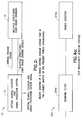
- FIG. 3is a basic schematic of a spectral-response division multiplexed Bragg grating sensor array.
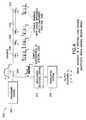
- FIG. 4is a basic schematic of a spectral-code division multiplexed Bragg grating sensor array.
- FIG. 4 ais a block diagram of a wavelength detection system shown in FIG. 4 .
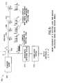
- FIG. 5is a basic schematic of a spectral-code time division multiplexed Bragg grating sensor array.
- FIG. 2The Basic Invention
- FIG. 2shows a new and unique sensor system generally indicated as 10 for sensing a parameter, including temperature or strain, having an optical source, coupler and signal processor system 12 in combination with multiple structured fiber Bragg gratings 14 .
- the optical source, coupler and signal processor system 12provides an optical source signal to the multiple structured fiber Bragg gratings 14 .
- the optical source, coupler and signal processor system 12also responds to multiple structured fiber Bragg grating signals, for providing an optical source, coupler and signal processor system signal containing information about a sensed parameter.
- the multiple structured fiber Bragg gratings 14respond to the optical source signal, and further respond to the sensed parameter, for providing the multiple structured fiber Bragg grating signals containing information about a complex superposition of spectral responses or codes related to the sensed parameter.
- FIG. 3Spectral Response
- FIG. 3shows one embodiment of the sensor system generally indicated as 100 and consistent with the sensor system 10 shown in FIG. 2 .
- the sensor system 100uses broadband responses, where the grating responses comprises multiple spectra.
- a broadband source 102provides via a coupler 104 a broadband optical light signal to multiple structured gratings 106 , 108 , 110 , . . . , 112 (FBG 1 , FBG 2 , FBG 3 , FBG 4 ).
- Each of the multiple structured gratings 106 , 108 , 110 , . . . , 112has different spacings of their spectral components (frequency) as shown in FIG. 3 and are serially configured.
- the reflected signal from the arrayin the form of multiple fiber Bragg grating signals, comprises a complex overlapping superposition of the multi-spectral line grating reflection spectra (aka spectral responses), and is coupled via a coupler 104 to a wavelength detection system 114 .
- a scanning filter, or other wavelength-resolving instrumentcan be used to detect the net spectral return from the array.
- the signal processing systemincludes the wavelength detection system 114 and a correlation system 116 .
- the wavelength detection system 114provides a wavelength detection system signal to a correlation system 116 . If a spectral line spacing of each of the multiple structured gratings 106 , 108 , 110 , . . . , 112 is known a priori, the correlation system 116 uses correlation based matched filtering to determine the shift in the position of a respective centroid wavelength of each of the multiple structured gratings 106 , 108 , 110 , . . . , 112 in the array. In operation, the wavelength detection system 114 stores the spectral characteristics of each grating and then correlates the total output with the stored response. The correlation process leads to the determination of the centroid wavelength of the sensor gratings in the array.
- the “code” used in the above exampleis a simple “frequency” based code, i.e. the spacing between the grating spectral lines is used to discriminate between gratings. This approach results in a limited ability to multiplex gratings due to the limited range of component spacings which can be effectively used.
- the broadband source 102 , coupler 104 , multiple structured gratings 106 , 108 , 110 , . . . , 112 (FBG 1 , FBG 2 , FBG 3 , FBG 4 ), wavelength detection system 114 and correlation system 116are all known in the art, and the scope of the invention is not intended to be limited to any particular type or kind thereof.
- FIG. 4Spectral Coding
- FIG. 4shows another embodiment of the sensor system generally indicated as 200 .
- the reference numerals used in FIG. 4are substantially the same for similar elements as the reference numerals used in FIG. 3 with the addition of 100 .
- a broadband source 202provides via a coupler 204 a broadband optical light signal to multiple structured gratings 206 , 208 , 210 , . . . , 212 (FBG 1 , FBG 2 , FBG 3 , FBG 4 ).
- Each of the multiple structured gratings 206 , 208 , 210 , . . . , 212has separate gratings with a unique broadband (multi-component) spectral code.
- the multiple structured gratings 206 , 208 , 210 , . . . , 212provide multiple structured grating signals having a complex superposition of spectral codes via the coupler 204 back to the wavelength detection system 214 .
- the sensor system 200utilizes a more complex code applied to multiple structured gratings 206 , 208 , 210 , . . . , 212 than the sensor system in FIG. 3 .
- the complex codecan be produced by using a noise-like code amplitude modulation of the multiple structured gratings 206 , 208 , 210 , . . . , 212 .
- Noise codes with the appropriate characteristicsinclude maximal-sequence codes (m-codes) and Gold codes. Both types of noise codes are routinely used in spread spectrum type communications systems, for example.
- code modulationpermits each grating spectral response to be characterized by a particular code, represented by logical “1”s and “0”s by the existence or lack of a reflection peak at a series of predetermined wavelengths.
- the type of coding desiredmay be produced either via the amplitude encoding of the grating (through a noise code on the amplitude), or by writing multiple grating components (i.e. separately writing each spectral component) at each sensor point.
- Such composite multi-grating sensorscould be produced with the gratings written over each other (collocated) or immediately adjacent to each other (or a combination of the two).
- the scope of the inventionis not intended to be limited to any particular noise code, or the manner in which the code is imparted in the optical fiber.
- This type of spectral code based interrogationwould allow a number of sensors, each with its own unique code, to occupy the same wavelength space.
- the strong auto-correlation characteristics of such codeswould also permit accurate determination of the centroid wavelength.
- the Wavelength Detection System 214The Wavelength Detection System 214
- the wavelength detection system 214 and the correlation system 216are two separate and distinct systems that perform different functions.
- the broadband source 202is used and separate spectral codes are reflected from the gratings 106 , 108 , 110 , 112 to the wavelength detection system 214 .
- FIG. 4 ashows the wavelength detection system 214 which includes a scanning filter 214 a and a power detector 214 b.
- the scanning filter 214 ascans for a particular wavelength and then passes it to the power detector 214 b.
- the power detector 214 bresponds to a scanning filter signal containing information about the particular wavelength, and provides a power spectral density signal to the correlation system 216 .
- FIG. 5Spectral Coding Time With Division Multiplexing
- FIG. 5shows still another embodiment of the sensor system generally indicated as 300 .
- the reference numerals used in FIG. 5are substantially the same for similar elements as the reference numerals used in FIG. 4 with the addition of 100 .
- a scanning laser 302provides via a coupler 304 a scanning laser optical light signal to multiple structured gratings 306 , 308 , 310 , . . . , 312 (FBG 1 , FBG 2 , FBG 3 , FBG 4 ).
- Each of the multiple structured gratings 306 , 308 , 310 , . . . , 312has separate gratings with a unique broadband (multi-component) spectral code.
- the multiple structured gratings 306 , 308 , 310 , . . . , 312provide multiple structured grating signals having a complex superposition of spectral codes via the coupler 304 back to the wavelength detection system 314 .
- the broadband source 202(FIG. 4) is replaced by the scanning laser source 302 (FIG. 5) that produces a single wavelength of light on a time dependent schedule.
- the detection system 314comprises only a detector (indicated as 314 ) that receives the reflected wavelengths that are coincident with the particular gratings in a time dependent fashion.
- the detector 314provides the same type of power spectral density signal to the correlation system 316 .
- the benefit of this embodimentis that the scanning laser source 302 can provide a higher power level at a particular wavelength than the broadband source 202 in FIG. 4 is capable of providing. It further makes the detection system 314 less complicated.
- the alternative sensor system 300utilizes a more complex code applied to multiple structured gratings 206 , 208 , 210 , . . . , 212 than the sensor system in FIG. 3 .
- the broadband source, scanning laser, couplers, multiple structured gratings, wavelength detection systems and correlation systemsare all elements that are known in the art, and the scope of the invention is not intended to be limited to any particular type or kind thereof.
Landscapes
- Physics & Mathematics (AREA)
- General Physics & Mathematics (AREA)
- Optical Transform (AREA)
Abstract
Description
1. Technical Field
The present invention relates to a Bragg grating sensor system in which resonance characteristics of a grating reflector are tailored to provide each sensor element in a series of elements with a unique spectral identity, or signature. Unlike normal grating sensors, where the gratings need to be separated in wavelength, this feature allows several gratings to occupy the same wavelength space. The overlapping spectral features of each grating are detected via the use of a spectral, matched filter correlation technique.
2. Description of Related Art
FIG. 1 shows a sensor system that is known in the art and includes fiber Bragg grating based sensors that provide a wavelength encoded mode of operation. To multiplex several sensors along a fiber, each grating is typically assigned a certain wavelength range over which it is to operate. This method of wavelength division multiplexing (WDM) limits the number of sensors which can be multiplexed, particularly if the gratings are subjected to large strains or temperature changes which give rise to large wavelength shifts. For example, a fiber strain of about +/−1% requires an operational range of greater than +/−10 nanometers at 1.3 micrometers. For a source of 40 nanometer bandwidth, only 2 sensors could be accommodated under the source profile with this strain monitoring range sequence. In effect, in FIG. 1 the basic mode of operation of a wavelength division multiplexing (WDM) system (prior art) uses narrow spectral responses from each grating to make the measurement and provide discrimination between sensors.
In using Bragg gratings as sensors, it is often advantageous to maximize the responsivity, or scale factor. For example, in the transduction of pressure to strain, the larger the pressure-to-strain conversion factor (within constraints set by possible breakage of the fiber), the lower the minimum detectable pressure change will be for a given wavelength resolution capability. Unfortunately, when multiplexing grating sensors, the limited wavelength range that can be assigned to each sensor limits the responsivity that can be used.
The present invention provides a new and unique sensor system for sensing a parameter, comprising an optical source, coupler and signal processor system in combination with multiple structured fiber Bragg gratings.
The optical source, coupler and signal processor system provides an optical source signal to the multiple structured fiber Bragg gratings. The optical source, coupler and signal processor system also responds to multiple structured fiber Bragg grating signals, for providing an optical source signal, and also for providing an optical source, coupler and signal processor system signal containing information about a sensed parameter.
The multiple structured fiber Bragg gratings respond to the optical source signal, and further respond to the sensed parameter, for providing the multiple structured fiber Bragg grating signals containing information about a complex superposition of spectral responses or codes related to the sensed parameter.
Each of the multiple structured fiber Bragg gratings has a different spacing of one or more spectral components that are used to discriminate between the multiple structured fiber Bragg gratings.
Each of the multiple structured fiber Bragg gratings includes a respective broadband spectral response or code related to the sensed parameter. For example, each of the multiple structured fiber Bragg gratings may have separate gratings with either a unique broadband, multi-component, spectral response or spectral code. Each of the multiple structured fiber Bragg gratings may have a respective noise code. The respective noise code may include either maximal sequence codes or Gold codes.
The optical source, coupler and signal processing system may include either a broadband source or a scanning laser, or a broadband source with a scanning filter.
The optical source, coupler and signal processing system may also include either a scanning filter or wavelength resolving instrument to detect a net spectral response from the multi-structured fiber Bragg grating combination, or a simple detector, depending on the source as described above.
In contrast to the prior grating based sensor system, in the present invention each grating in the arrangement has a broadband response, typically giving a multi-component response. This type of response can be produced by writing a grating through a suitable amplitude mask. This type of grating is characterized by a central peak and a series of “sideband” peaks. These sidebands result due to the amplitude superstructure modulation of the grating. The spacing between the grating spectral components depends on the period of the superstructure amplitude mask period. The grating produced has a nominal center wavelength, or centroid wavelength which shifts with grating temperature or strain as with a “normal” narrowband grating.
In addition, the present invention also provides an approach to the multiplexing of gratings using a spectral coding approach which allows gratings to be used over the same wavelength range. The sensors are not wavelength division multiplexed (WDM), but spectral-code division multiplexed (SCDM).
The foregoing and other objects, features and advantages of the present invention will become more apparent in light of the following detailed description of exemplary embodiments thereof, as illustrated in the accompanying drawing.
FIG. 1 is a basic schematic of a wavelength multiplexed Bragg grating sensor array.
FIG. 2 is a block diagram of a Bragg grating sensor system that is the subject matter of the present patent application.
FIG. 3 is a basic schematic of a spectral-response division multiplexed Bragg grating sensor array.
FIG. 4 is a basic schematic of a spectral-code division multiplexed Bragg grating sensor array.
FIG. 4ais a block diagram of a wavelength detection system shown in FIG.4.
FIG. 5 is a basic schematic of a spectral-code time division multiplexed Bragg grating sensor array.
FIG.2: The Basic Invention
FIG. 2 shows a new and unique sensor system generally indicated as10 for sensing a parameter, including temperature or strain, having an optical source, coupler andsignal processor system 12 in combination with multiple structured fiber Bragggratings 14.
The optical source, coupler andsignal processor system 12 provides an optical source signal to the multiple structured fiber Bragggratings 14. The optical source, coupler andsignal processor system 12 also responds to multiple structured fiber Bragg grating signals, for providing an optical source, coupler and signal processor system signal containing information about a sensed parameter.
The multiple structured fiber Bragggratings 14 respond to the optical source signal, and further respond to the sensed parameter, for providing the multiple structured fiber Bragg grating signals containing information about a complex superposition of spectral responses or codes related to the sensed parameter.
FIG.3: Spectral Response
FIG. 3 shows one embodiment of the sensor system generally indicated as100 and consistent with thesensor system 10 shown in FIG.2.
Thesensor system 100 uses broadband responses, where the grating responses comprises multiple spectra. In FIG. 3, abroadband source 102 provides via a coupler104 a broadband optical light signal to multiple structuredgratings gratings gratings gratings gratings coupler 104 to awavelength detection system 114. A scanning filter, or other wavelength-resolving instrument, can be used to detect the net spectral return from the array.
The signal processing system includes thewavelength detection system 114 and acorrelation system 116. Thewavelength detection system 114 provides a wavelength detection system signal to acorrelation system 116. If a spectral line spacing of each of the multiple structuredgratings correlation system 116 uses correlation based matched filtering to determine the shift in the position of a respective centroid wavelength of each of the multiple structuredgratings wavelength detection system 114 stores the spectral characteristics of each grating and then correlates the total output with the stored response. The correlation process leads to the determination of the centroid wavelength of the sensor gratings in the array.
The “code” used in the above example is a simple “frequency” based code, i.e. the spacing between the grating spectral lines is used to discriminate between gratings. This approach results in a limited ability to multiplex gratings due to the limited range of component spacings which can be effectively used.
Thebroadband source 102,coupler 104, multiplestructured gratings wavelength detection system 114 andcorrelation system 116 are all known in the art, and the scope of the invention is not intended to be limited to any particular type or kind thereof.
FIG.4: Spectral Coding
FIG. 4 shows another embodiment of the sensor system generally indicated as200. The reference numerals used in FIG. 4 are substantially the same for similar elements as the reference numerals used in FIG. 3 with the addition of100.
In FIG. 4, abroadband source 202 provides via a coupler204 a broadband optical light signal to multiplestructured gratings structured gratings structured gratings coupler 204 back to thewavelength detection system 214.
Thesensor system 200 utilizes a more complex code applied to multiplestructured gratings structured gratings
This type of spectral code based interrogation would allow a number of sensors, each with its own unique code, to occupy the same wavelength space. The strong auto-correlation characteristics of such codes would also permit accurate determination of the centroid wavelength.
In FIG. 4, thewavelength detection system 214 and thecorrelation system 216 are two separate and distinct systems that perform different functions.
In this embodiment, thebroadband source 202 is used and separate spectral codes are reflected from thegratings wavelength detection system 214. FIG. 4ashows thewavelength detection system 214 which includes ascanning filter 214aand apower detector 214b.Thescanning filter 214ascans for a particular wavelength and then passes it to thepower detector 214b.Thepower detector 214bresponds to a scanning filter signal containing information about the particular wavelength, and provides a power spectral density signal to thecorrelation system 216.
FIG.5: Spectral Coding Time With Division Multiplexing
FIG. 5 shows still another embodiment of the sensor system generally indicated as300. The reference numerals used in FIG. 5 are substantially the same for similar elements as the reference numerals used in FIG. 4 with the addition of100.
In FIG. 5, ascanning laser 302 provides via a coupler304 a scanning laser optical light signal to multiplestructured gratings
Each of the multiplestructured gratings structured gratings coupler 304 back to thewavelength detection system 314.
In comparison to the embodiment in FIG. 4, the broadband source202 (FIG. 4) is replaced by the scanning laser source302 (FIG. 5) that produces a single wavelength of light on a time dependent schedule. In this embodiment, thedetection system 314 comprises only a detector (indicated as314) that receives the reflected wavelengths that are coincident with the particular gratings in a time dependent fashion. Thedetector 314 provides the same type of power spectral density signal to thecorrelation system 316. The benefit of this embodiment is that thescanning laser source 302 can provide a higher power level at a particular wavelength than thebroadband source 202 in FIG. 4 is capable of providing. It further makes thedetection system 314 less complicated.
Similar to the embodiment in FIG. 4, thealternative sensor system 300 utilizes a more complex code applied to multiplestructured gratings
The broadband source, scanning laser, couplers, multiple structured gratings, wavelength detection systems and correlation systems are all elements that are known in the art, and the scope of the invention is not intended to be limited to any particular type or kind thereof.
Although the invention has been described and illustrated with respect to exemplary embodiments thereof, the foregoing and various other additions and omissions may be made therein and thereto without departing from the spirit and scope of the present invention.
Claims (21)
1. A sensor system for sensing a parameter, comprising:
an optical source, coupler and signal processor system, for providing an optical source signal, responsive to multiple structured fiber Bragg grating signals, for providing an optical source, coupler and signal processor system containing information about a sensed parameter; and
multiple structured fiber Bragg gratings, responsive to the optical source signal, and further responsive to the sensed parameter, for providing the multiple structured fiber Bragg grating signals containing information about a complex superposition of spectral responses or codes related to the sensed parameter.
2. A sensor system according toclaim 1 ,
wherein each of the multiple structured fiber Bragg gratings includes a respective broadband spectral response or code related to the sensed parameter.
3. A sensor system according toclaim 1 ,
wherein the optical source, coupler and signal processing system includes a broadband light source, a coupler, a wavelength detection system and a correlation system;
wherein the broadband light source provides the optical source signal;
wherein the coupler responds to the optical signal, for providing a coupled optical signal to the multi-structured fiber Bragg gratings, and responds to the multiple structured fiber Bragg grating signals, for providing coupled multiple structured fiber Bragg grating signals;
wherein the wavelength detection system responds to the coupled multiple structured fiber Bragg grating signals, for providing a wavelength detection system signal containing information about a wavelength detection of the multiple structured fiber Bragg grating signals; and
wherein the correlation system responds to the wavelength detection system signal, for providing a correlation system signal containing information about the sensed parameter.
4. A sensor system according toclaim 1 ,
wherein each of the multiple structured fiber Bragg gratings has a different spacing of a respective spectral component that is used to discriminate between the multiple structured fiber Bragg gratings.
5. A sensor system according toclaim 4 ,
wherein the multiple structured fiber Bragg gratings are serially configured.
6. A sensor system according toclaim 1 ,
wherein the optical source, coupler and signal processing system includes either a scanning filter or wavelength resolving instrument to detect a net spectral response from the multi-structured fiber Bragg gratings.
7. A sensor system according toclaim 1 , wherein each of the multiple structured fiber Bragg gratings has separate gratings with a unique broadband, multi-component, spectral response.
8. A sensor system according toclaim 1 ,
wherein each of the multiple structured fiber Bragg gratings has separate gratings with a unique broadband, multi-component, spectral code.
9. A sensor system according toclaim 1 ,
wherein each of the multiple structured fiber Bragg gratings has a respective noise code.
10. A sensor system according toclaim 9 ,
wherein the respective noise code includes either maximal sequence codes or Gold codes.
11. A sensor system according toclaim 3 , wherein the wavelength detection system includes a scanning filter and a power detector, the scanning filter scanning for a particular wavelength for passing to the power detector.
12. A sensor system according toclaim 1 ,
wherein the optical source, coupler and signal processing system includes a scanning laser, a coupler, a wavelength detection system and a correlation system;
wherein the scanning laser provides the optical source signal in the form of a scanning laser signal;
wherein the coupler responds to the scanning laser signal, for providing a coupled scanning laser signal to the multiple structured fiber Bragg gratings, and responds to the multiple structured fiber Bragg grating signals, for providing coupled multiple structured fiber Bragg grating signals;
wherein the wavelength detection system responds to the coupled multiple structured fiber Bragg grating signals, for providing a wavelength detection system signal containing information about a wavelength detection of the multiple structured fiber Bragg grating signals; and
wherein the correlation system responds to the wavelength detection system signal, for providing a correlation system signal containing information about the sensed parameter.
13. A sensor system according toclaim 12 , wherein the wavelength detection system comprises a detector that receives reflected wavelengths that are coincident with a respective multiple structured fiber Bragg grating in a time dependent fashion.
14. A sensor system for sensing a parameter having an optical source and a signal processor system,
characterized in that the sensor system comprises multiple structured fiber Bragg gratings that respond to an optical source signal from the optical source, and further respond to a sensed parameter, for providing multiple structured fiber Bragg grating signals containing information about a complex superposition of spectral responses or codes related to the sensed parameter.
15. A sensor system according toclaim 14 ,
wherein each of the multiple structured fiber Bragg gratings includes a respective broadband spectral response or code related to the sensed parameter.
16. A sensor system according toclaim 14 ,
wherein each of the multiple structured fiber Bragg gratings has a different spacing of a respective spectral component that is used to discriminate between the multiple structured fiber Bragg gratings.
17. A sensor system according toclaim 16 ,
wherein the multiple structured fiber Bragg gratings are serially configured.
18. A sensor system according toclaim 14 ,
wherein each of the multiple structured fiber Bragg gratings has separate gratings with a unique broadband, multi-component, spectral response.
19. A sensor system according toclaim 14 ,
wherein each of the multiple structured fiber Bragg gratings has separate gratings with a unique broadband, multi-component, spectral code.
20. A sensor system according toclaim 14 ,
wherein each of the multiple structured fiber Bragg gratings has a respective noise code.
21. A sensor system according toclaim 20 ,
wherein the respective noise codes include either maximal sequence codes or Gold codes.
Priority Applications (1)
| Application Number | Priority Date | Filing Date | Title |
|---|---|---|---|
| US09/545,792US6489606B1 (en) | 2000-04-07 | 2000-04-07 | Bragg grating sensor system with spectral response or code division multiplexing |
Applications Claiming Priority (1)
| Application Number | Priority Date | Filing Date | Title |
|---|---|---|---|
| US09/545,792US6489606B1 (en) | 2000-04-07 | 2000-04-07 | Bragg grating sensor system with spectral response or code division multiplexing |
Publications (1)
| Publication Number | Publication Date |
|---|---|
| US6489606B1true US6489606B1 (en) | 2002-12-03 |
Family
ID=24177562
Family Applications (1)
| Application Number | Title | Priority Date | Filing Date |
|---|---|---|---|
| US09/545,792Expired - LifetimeUS6489606B1 (en) | 2000-04-07 | 2000-04-07 | Bragg grating sensor system with spectral response or code division multiplexing |
Country Status (1)
| Country | Link |
|---|---|
| US (1) | US6489606B1 (en) |
Cited By (49)
| Publication number | Priority date | Publication date | Assignee | Title |
|---|---|---|---|---|
| US20020054408A1 (en)* | 2000-11-07 | 2002-05-09 | Ho-Joon Lee | Signal processing system of multiplexed fiber bragg grating sensor using CDMA |
| US20030194167A1 (en)* | 2002-04-10 | 2003-10-16 | National Tsing Hua University | Dual fiber bragg grating strain sensor system |
| US20040067003A1 (en)* | 2002-10-02 | 2004-04-08 | Mikhail Chliaguine | Fiber-optic sensing system for distributed detection and localization of alarm conditions |
| US20040136652A1 (en)* | 2001-02-13 | 2004-07-15 | Groves-Kirkby Christopher John | Optical waveguide bragg grating system |
| US20050077455A1 (en)* | 2003-08-13 | 2005-04-14 | Townley-Smith Paul A. | Perimeter detection |
| GB2414796A (en)* | 2004-06-04 | 2005-12-07 | Weatherford Lamb | Optical wavelength determination using multiple measurable features |
| US7092160B2 (en) | 2002-09-12 | 2006-08-15 | Illumina, Inc. | Method of manufacturing of diffraction grating-based optical identification element |
| US7106513B2 (en) | 2002-08-20 | 2006-09-12 | Illumina, Inc. | Diffraction grating-based encoded particle |
| US7126755B2 (en) | 2002-09-12 | 2006-10-24 | Moon John A | Method and apparatus for labeling using diffraction grating-based encoded optical identification elements |
| US7164533B2 (en) | 2003-01-22 | 2007-01-16 | Cyvera Corporation | Hybrid random bead/chip based microarray |
| US7190522B2 (en) | 2002-09-12 | 2007-03-13 | Cyvera Corporation | Chemical synthesis using diffraction grating-based encoded optical elements |
| US20070264012A1 (en)* | 2004-09-30 | 2007-11-15 | Peter Healey | Identifying or Locating Waveguides |
| US7349158B2 (en) | 2002-09-12 | 2008-03-25 | Cyvera Corporation | Diffraction grating-based encoded micro-particles for multiplexed experiments |
| US20080123085A1 (en)* | 2004-12-17 | 2008-05-29 | Sikora Edmund Sr | Assessing A Network |
| US7399643B2 (en) | 2002-09-12 | 2008-07-15 | Cyvera Corporation | Method and apparatus for aligning microbeads in order to interrogate the same |
| US20080219660A1 (en)* | 2005-03-31 | 2008-09-11 | Peter Healey | Communicating Information |
| US7433123B2 (en) | 2004-02-19 | 2008-10-07 | Illumina, Inc. | Optical identification element having non-waveguide photosensitive substrate with diffraction grating therein |
| US7441703B2 (en) | 2002-08-20 | 2008-10-28 | Illumina, Inc. | Optical reader for diffraction grating-based encoded optical identification elements |
| US7508608B2 (en) | 2004-11-17 | 2009-03-24 | Illumina, Inc. | Lithographically fabricated holographic optical identification element |
| US7602952B2 (en) | 2004-11-16 | 2009-10-13 | Illumina, Inc. | Scanner having spatial light modulator |
| US7604173B2 (en) | 2004-11-16 | 2009-10-20 | Illumina, Inc. | Holographically encoded elements for microarray and other tagging labeling applications, and method and apparatus for making and reading the same |
| US7619819B2 (en) | 2002-08-20 | 2009-11-17 | Illumina, Inc. | Method and apparatus for drug product tracking using encoded optical identification elements |
| US7623624B2 (en) | 2005-11-22 | 2009-11-24 | Illumina, Inc. | Method and apparatus for labeling using optical identification elements characterized by X-ray diffraction |
| US7817279B2 (en) | 2006-02-24 | 2010-10-19 | British Telecommunications Public Limited Company | Sensing a disturbance |
| US7830575B2 (en) | 2006-04-10 | 2010-11-09 | Illumina, Inc. | Optical scanner with improved scan time |
| US7872804B2 (en) | 2002-08-20 | 2011-01-18 | Illumina, Inc. | Encoded particle having a grating with variations in the refractive index |
| US7900836B2 (en) | 2002-08-20 | 2011-03-08 | Illumina, Inc. | Optical reader system for substrates having an optically readable code |
| US7901630B2 (en) | 2002-08-20 | 2011-03-08 | Illumina, Inc. | Diffraction grating-based encoded microparticle assay stick |
| US7914988B1 (en) | 2006-03-31 | 2011-03-29 | Illumina, Inc. | Gene expression profiles to predict relapse of prostate cancer |
| US7923260B2 (en) | 2002-08-20 | 2011-04-12 | Illumina, Inc. | Method of reading encoded particles |
| US7961331B2 (en) | 2006-02-24 | 2011-06-14 | British Telecommunications Public Limited Company | Sensing a disturbance along an optical path |
| CN102095437A (en)* | 2011-01-11 | 2011-06-15 | 北京交通大学 | Real-time positioning and detection system for train by intensive fiber grating group |
| CN102107666A (en)* | 2011-01-11 | 2011-06-29 | 北京交通大学 | Serial optical fiber grating railway safety running monitoring system |
| US7974182B2 (en) | 2004-03-31 | 2011-07-05 | British Telecommunications Public Limited Company | Evaluating the position of a disturbance |
| US7995197B2 (en) | 2004-09-30 | 2011-08-09 | British Telecommunications Public Limited Company | Distributed backscattering |
| US8000609B2 (en) | 2005-04-14 | 2011-08-16 | British Telecommunications Public Limited Company | Communicating or reproducing an audible sound |
| US8027584B2 (en) | 2006-02-24 | 2011-09-27 | British Telecommunications Public Limited Company | Sensing a disturbance |
| US8081792B2 (en) | 2003-08-20 | 2011-12-20 | Illumina, Inc. | Fourier scattering methods for encoding microbeads and methods and apparatus for reading the same |
| US8470605B2 (en) | 2002-09-12 | 2013-06-25 | Illumina, Inc. | Optical reader for reading encoded microparticles |
| US20130266321A1 (en)* | 2012-04-05 | 2013-10-10 | Gwangju Institute Of Science And Technology | Sensing apparatus |
| CN103487074A (en)* | 2013-10-12 | 2014-01-01 | 重庆邮电大学 | Method for processing FBG (fiber bragg grating) sensing signal by utilizing three-point peek-seeking algorithm |
| US8670662B2 (en) | 2006-04-03 | 2014-03-11 | British Telecommunications Public Limited Company | Evaluating the position of an optical fiber disturbance |
| US8778849B2 (en) | 2011-10-28 | 2014-07-15 | Illumina, Inc. | Microarray fabrication system and method |
| US8778848B2 (en) | 2011-06-09 | 2014-07-15 | Illumina, Inc. | Patterned flow-cells useful for nucleic acid analysis |
| WO2015109234A1 (en) | 2014-01-16 | 2015-07-23 | Illumina, Inc. | Gene expression panel for prognosis of prostate cancer recurrence |
| US10823625B1 (en)* | 2019-05-20 | 2020-11-03 | Kidde Technologies, Inc. | Overheat testing apparatus for optical fiber |
| US10948363B2 (en) | 2019-05-20 | 2021-03-16 | Kidde Technologies, Inc. | Overheat testing apparatus for optical fiber |
| US11561119B2 (en)* | 2018-10-04 | 2023-01-24 | Fbgs Technologies Gmbh | Interrogation of optical fiber sensor networks |
| US11639862B1 (en)* | 2009-09-15 | 2023-05-02 | Astro Technology Group, Llc | Apparatus, system and method enabling multiplexed arrangement of optical fiber for sensing of operating conditions within a structural member |
Citations (2)
| Publication number | Priority date | Publication date | Assignee | Title |
|---|---|---|---|---|
| US5426297A (en)* | 1993-09-27 | 1995-06-20 | United Technologies Corporation | Multiplexed Bragg grating sensors |
| US6285806B1 (en)* | 1998-05-31 | 2001-09-04 | The United States Of America As Represented By The Secretary Of The Navy | Coherent reflectometric fiber Bragg grating sensor array |
- 2000
- 2000-04-07USUS09/545,792patent/US6489606B1/ennot_activeExpired - Lifetime
Patent Citations (2)
| Publication number | Priority date | Publication date | Assignee | Title |
|---|---|---|---|---|
| US5426297A (en)* | 1993-09-27 | 1995-06-20 | United Technologies Corporation | Multiplexed Bragg grating sensors |
| US6285806B1 (en)* | 1998-05-31 | 2001-09-04 | The United States Of America As Represented By The Secretary Of The Navy | Coherent reflectometric fiber Bragg grating sensor array |
Cited By (84)
| Publication number | Priority date | Publication date | Assignee | Title |
|---|---|---|---|---|
| US6892031B2 (en)* | 2000-11-07 | 2005-05-10 | Ho-Joon Lee | Signal processing system of multiplexed fiber bragg grating sensor using CDMA |
| US20020054408A1 (en)* | 2000-11-07 | 2002-05-09 | Ho-Joon Lee | Signal processing system of multiplexed fiber bragg grating sensor using CDMA |
| US20040136652A1 (en)* | 2001-02-13 | 2004-07-15 | Groves-Kirkby Christopher John | Optical waveguide bragg grating system |
| US20030194167A1 (en)* | 2002-04-10 | 2003-10-16 | National Tsing Hua University | Dual fiber bragg grating strain sensor system |
| US6829397B2 (en)* | 2002-04-10 | 2004-12-07 | National Tsing Hua University | Dual fiber bragg grating strain sensor system |
| US8333325B2 (en) | 2002-08-20 | 2012-12-18 | Illumina, Inc. | Optical reader system for substrates having an optically readable code |
| US7901630B2 (en) | 2002-08-20 | 2011-03-08 | Illumina, Inc. | Diffraction grating-based encoded microparticle assay stick |
| US8614852B2 (en) | 2002-08-20 | 2013-12-24 | Illumina, Inc. | Elongated microparticles having an optically detectable code configured to at least one of reflect or filter light |
| US7441703B2 (en) | 2002-08-20 | 2008-10-28 | Illumina, Inc. | Optical reader for diffraction grating-based encoded optical identification elements |
| US8498052B2 (en) | 2002-08-20 | 2013-07-30 | Illumina, Inc. | Composition including an item and an encoded optical substrate and a method for identifying an item |
| US7619819B2 (en) | 2002-08-20 | 2009-11-17 | Illumina, Inc. | Method and apparatus for drug product tracking using encoded optical identification elements |
| US7106513B2 (en) | 2002-08-20 | 2006-09-12 | Illumina, Inc. | Diffraction grating-based encoded particle |
| US7872804B2 (en) | 2002-08-20 | 2011-01-18 | Illumina, Inc. | Encoded particle having a grating with variations in the refractive index |
| US7900836B2 (en) | 2002-08-20 | 2011-03-08 | Illumina, Inc. | Optical reader system for substrates having an optically readable code |
| US7923260B2 (en) | 2002-08-20 | 2011-04-12 | Illumina, Inc. | Method of reading encoded particles |
| US7092160B2 (en) | 2002-09-12 | 2006-08-15 | Illumina, Inc. | Method of manufacturing of diffraction grating-based optical identification element |
| US7190522B2 (en) | 2002-09-12 | 2007-03-13 | Cyvera Corporation | Chemical synthesis using diffraction grating-based encoded optical elements |
| US7349158B2 (en) | 2002-09-12 | 2008-03-25 | Cyvera Corporation | Diffraction grating-based encoded micro-particles for multiplexed experiments |
| US7375890B2 (en) | 2002-09-12 | 2008-05-20 | Cyvera Corporation | Method of manufacturing of a diffraction grating-based optical identification element |
| US7126755B2 (en) | 2002-09-12 | 2006-10-24 | Moon John A | Method and apparatus for labeling using diffraction grating-based encoded optical identification elements |
| US7399643B2 (en) | 2002-09-12 | 2008-07-15 | Cyvera Corporation | Method and apparatus for aligning microbeads in order to interrogate the same |
| US7898735B2 (en) | 2002-09-12 | 2011-03-01 | Illumina, Inc. | Methods and systems for writing an optical code within or on a fiber substrate |
| US8470605B2 (en) | 2002-09-12 | 2013-06-25 | Illumina, Inc. | Optical reader for reading encoded microparticles |
| US20040067003A1 (en)* | 2002-10-02 | 2004-04-08 | Mikhail Chliaguine | Fiber-optic sensing system for distributed detection and localization of alarm conditions |
| US6876786B2 (en)* | 2002-10-02 | 2005-04-05 | Cicese-Centro De Investigation | Fiber-optic sensing system for distributed detection and localization of alarm conditions |
| US7164533B2 (en) | 2003-01-22 | 2007-01-16 | Cyvera Corporation | Hybrid random bead/chip based microarray |
| US8049893B2 (en) | 2003-01-22 | 2011-11-01 | Illumina, Inc. | Methods of identifying analytes and using encoded particles |
| US7659983B2 (en) | 2003-01-22 | 2010-02-09 | Electronics And Telecommunications Resarch Institute | Hybrid random bead/chip based microarray |
| US9268983B2 (en) | 2003-01-22 | 2016-02-23 | Illumina, Inc. | Optical system and method for reading encoded microbeads |
| US7843567B2 (en) | 2003-01-22 | 2010-11-30 | Illumina, Inc. | Methods of identifying an analyte and nucleic acid analysis |
| US20050077455A1 (en)* | 2003-08-13 | 2005-04-14 | Townley-Smith Paul A. | Perimeter detection |
| US7488929B2 (en)* | 2003-08-13 | 2009-02-10 | Zygo Corporation | Perimeter detection using fiber optic sensors |
| US8081792B2 (en) | 2003-08-20 | 2011-12-20 | Illumina, Inc. | Fourier scattering methods for encoding microbeads and methods and apparatus for reading the same |
| US8565475B2 (en) | 2003-08-20 | 2013-10-22 | Illumina, Inc. | Optical system and method for reading encoded microbeads |
| US7433123B2 (en) | 2004-02-19 | 2008-10-07 | Illumina, Inc. | Optical identification element having non-waveguide photosensitive substrate with diffraction grating therein |
| US7791802B2 (en) | 2004-02-19 | 2010-09-07 | Illumina, Inc. | Optical identification element having a non-waveguide substrate |
| US7974182B2 (en) | 2004-03-31 | 2011-07-05 | British Telecommunications Public Limited Company | Evaluating the position of a disturbance |
| US20050269489A1 (en)* | 2004-06-04 | 2005-12-08 | Domino Taverner | Optical wavelength determination using multiple measurable features |
| GB2414796A (en)* | 2004-06-04 | 2005-12-07 | Weatherford Lamb | Optical wavelength determination using multiple measurable features |
| US7109471B2 (en) | 2004-06-04 | 2006-09-19 | Weatherford/Lamb, Inc. | Optical wavelength determination using multiple measurable features |
| GB2414796B (en)* | 2004-06-04 | 2009-05-20 | Weatherford Lamb | Optical wavelength determination using multiple measurable features |
| US20070264012A1 (en)* | 2004-09-30 | 2007-11-15 | Peter Healey | Identifying or Locating Waveguides |
| US7995197B2 (en) | 2004-09-30 | 2011-08-09 | British Telecommunications Public Limited Company | Distributed backscattering |
| US7602952B2 (en) | 2004-11-16 | 2009-10-13 | Illumina, Inc. | Scanner having spatial light modulator |
| US7604173B2 (en) | 2004-11-16 | 2009-10-20 | Illumina, Inc. | Holographically encoded elements for microarray and other tagging labeling applications, and method and apparatus for making and reading the same |
| US7796333B2 (en) | 2004-11-17 | 2010-09-14 | Illumina, Inc. | Encoded microparticles and a method for fabricating |
| US7508608B2 (en) | 2004-11-17 | 2009-03-24 | Illumina, Inc. | Lithographically fabricated holographic optical identification element |
| US8045174B2 (en) | 2004-12-17 | 2011-10-25 | British Telecommunications Public Limited Company | Assessing a network |
| US20080123085A1 (en)* | 2004-12-17 | 2008-05-29 | Sikora Edmund Sr | Assessing A Network |
| US8396360B2 (en)* | 2005-03-31 | 2013-03-12 | British Telecommunications Public Limited Company | Communicating information |
| US20080219660A1 (en)* | 2005-03-31 | 2008-09-11 | Peter Healey | Communicating Information |
| US8000609B2 (en) | 2005-04-14 | 2011-08-16 | British Telecommunications Public Limited Company | Communicating or reproducing an audible sound |
| US7623624B2 (en) | 2005-11-22 | 2009-11-24 | Illumina, Inc. | Method and apparatus for labeling using optical identification elements characterized by X-ray diffraction |
| US7961331B2 (en) | 2006-02-24 | 2011-06-14 | British Telecommunications Public Limited Company | Sensing a disturbance along an optical path |
| US8027584B2 (en) | 2006-02-24 | 2011-09-27 | British Telecommunications Public Limited Company | Sensing a disturbance |
| US7817279B2 (en) | 2006-02-24 | 2010-10-19 | British Telecommunications Public Limited Company | Sensing a disturbance |
| US7914988B1 (en) | 2006-03-31 | 2011-03-29 | Illumina, Inc. | Gene expression profiles to predict relapse of prostate cancer |
| US8440407B2 (en) | 2006-03-31 | 2013-05-14 | Illumina, Inc. | Gene expression profiles to predict relapse of prostate cancer |
| US20110153534A1 (en)* | 2006-03-31 | 2011-06-23 | Illumina, Inc. | Expression Profiles to Predict Relapse of Prostate Cancer |
| US8110363B2 (en) | 2006-03-31 | 2012-02-07 | Illumina, Inc. | Expression profiles to predict relapse of prostate cancer |
| US8670662B2 (en) | 2006-04-03 | 2014-03-11 | British Telecommunications Public Limited Company | Evaluating the position of an optical fiber disturbance |
| US7830575B2 (en) | 2006-04-10 | 2010-11-09 | Illumina, Inc. | Optical scanner with improved scan time |
| US11852885B2 (en) | 2009-09-15 | 2023-12-26 | Astro Technology Group, Llc | Apparatus, system and method enabling multiplexed arrangement of optical fiber for sensing of operating conditions within a structural member |
| US11867963B2 (en) | 2009-09-15 | 2024-01-09 | Astro Technology Group, Llc | Apparatus, system and method enabling multiplexed arrangement of optical fiber for sensing of operating conditions within a structural member |
| US11639862B1 (en)* | 2009-09-15 | 2023-05-02 | Astro Technology Group, Llc | Apparatus, system and method enabling multiplexed arrangement of optical fiber for sensing of operating conditions within a structural member |
| US11867964B2 (en) | 2009-09-15 | 2024-01-09 | Astro Technology Group, Llc | Apparatus, system and method enabling multiplexed arrangement of optical fiber for sensing of operating conditions within a structural member |
| CN102095437A (en)* | 2011-01-11 | 2011-06-15 | 北京交通大学 | Real-time positioning and detection system for train by intensive fiber grating group |
| CN102107666A (en)* | 2011-01-11 | 2011-06-29 | 北京交通大学 | Serial optical fiber grating railway safety running monitoring system |
| US8778848B2 (en) | 2011-06-09 | 2014-07-15 | Illumina, Inc. | Patterned flow-cells useful for nucleic acid analysis |
| US12163180B2 (en) | 2011-06-09 | 2024-12-10 | Illumina, Inc. | Patterned flow-cells useful for nucleic acid analysis |
| US10787698B2 (en) | 2011-06-09 | 2020-09-29 | Illumina, Inc. | Patterned flow-cells useful for nucleic acid analysis |
| US10280454B2 (en) | 2011-10-28 | 2019-05-07 | Illumina, Inc. | Microarray fabrication system and method |
| US9670535B2 (en) | 2011-10-28 | 2017-06-06 | Illumina, Inc. | Microarray fabrication system and method |
| US8778849B2 (en) | 2011-10-28 | 2014-07-15 | Illumina, Inc. | Microarray fabrication system and method |
| US11060135B2 (en) | 2011-10-28 | 2021-07-13 | Illumina, Inc. | Microarray fabrication system and method |
| US11834704B2 (en) | 2011-10-28 | 2023-12-05 | Illumina, Inc. | Microarray fabrication system and method |
| US8989573B2 (en)* | 2012-04-05 | 2015-03-24 | Gwangju Institute Of Science And Technology | Sensing apparatus |
| US20130266321A1 (en)* | 2012-04-05 | 2013-10-10 | Gwangju Institute Of Science And Technology | Sensing apparatus |
| CN103487074B (en)* | 2013-10-12 | 2015-08-05 | 重庆邮电大学 | Utilize the method for 3 peak-seeking algorithm process FBG transducing signals |
| CN103487074A (en)* | 2013-10-12 | 2014-01-01 | 重庆邮电大学 | Method for processing FBG (fiber bragg grating) sensing signal by utilizing three-point peek-seeking algorithm |
| WO2015109234A1 (en) | 2014-01-16 | 2015-07-23 | Illumina, Inc. | Gene expression panel for prognosis of prostate cancer recurrence |
| US11561119B2 (en)* | 2018-10-04 | 2023-01-24 | Fbgs Technologies Gmbh | Interrogation of optical fiber sensor networks |
| US10948363B2 (en) | 2019-05-20 | 2021-03-16 | Kidde Technologies, Inc. | Overheat testing apparatus for optical fiber |
| US10823625B1 (en)* | 2019-05-20 | 2020-11-03 | Kidde Technologies, Inc. | Overheat testing apparatus for optical fiber |
Similar Documents
| Publication | Publication Date | Title |
|---|---|---|
| US6489606B1 (en) | Bragg grating sensor system with spectral response or code division multiplexing | |
| US6252656B1 (en) | Apparatus and method of seismic sensing systems using fiber optics | |
| US6674928B2 (en) | Optical sensing device containing fiber Bragg gratings | |
| US6335524B1 (en) | High speed demodulation systems for fiber optic grating sensors | |
| US9810556B2 (en) | Apparatus for measuring optical signals from multiple optical fiber sensors | |
| US20040136652A1 (en) | Optical waveguide bragg grating system | |
| Johnson et al. | Fiber Bragg grating interrogation and multiplexing with a 3 3 coupler and a scanning filter | |
| CA2392982C (en) | Fiber bragg grating sensor system having enhanced strain-to-wavelength responsivity by using a spectral beating based vernier effect | |
| US6829397B2 (en) | Dual fiber bragg grating strain sensor system | |
| US6878926B2 (en) | Differential measurement system based on the use of pairs of Bragg gratings | |
| WO2000077562A1 (en) | Method and apparatus for interrogation of birefringent fbg sensors | |
| US6822218B2 (en) | Method of and apparatus for wavelength detection | |
| US6946645B2 (en) | Measuring system with sweeping comb filter and multiplexer | |
| US6075907A (en) | Dual wavelength interrogation sensor employing long-period gratings | |
| US6563969B2 (en) | Multiplexed fiber laser sensor system | |
| US20020109081A1 (en) | Measuring system with comb filter interferometer and multiplexer | |
| KR101297286B1 (en) | Device for measuring temperature using optical fiber | |
| Shlyagin et al. | Twin grating-based interferometric fiber sensor | |
| KR100952053B1 (en) | Fiber Bragg Grating Sensor System Using Spectrum Tracking Method | |
| Kersey | Multiplexed Bragg grating fiber sensors | |
| Breglio et al. | Chirped-pulsed frequency modulation (C-PFM) for fiber Bragg grating sensors multiplexing | |
| KR100275654B1 (en) | Grating strain sensor system using inclined fiber bragg grating demodulator | |
| Kersey | Monitoring structural performance with optical TDR techniques | |
| Ames | Multiplexed Fiber Laser Sensor System | |
| Todd et al. | Structural monitoring using a novel high-performance fiber optic measurement system |
Legal Events
| Date | Code | Title | Description |
|---|---|---|---|
| AS | Assignment | Owner name:CIDRA CORPORATION, CONNECTICUT Free format text:ASSIGNMENT OF ASSIGNORS INTEREST;ASSIGNORS:KERSEY, ALAN D.;RUBINO, ROBERT A.;DUNPHY, JAMES R.;REEL/FRAME:010707/0731 Effective date:20000405 | |
| STCF | Information on status: patent grant | Free format text:PATENTED CASE | |
| AS | Assignment | Owner name:CYVERA CORPORATION, CONNECTICUT Free format text:ASSIGNMENT OF ASSIGNORS INTEREST;ASSIGNOR:CIDRA CORPORATION;REEL/FRAME:015442/0921 Effective date:20031215 | |
| AS | Assignment | Owner name:ILLUMINA, INC., CALIFORNIA Free format text:ASSIGNMENT OF ASSIGNORS INTEREST;ASSIGNOR:CYVERA CORPORATION;REEL/FRAME:016580/0921 Effective date:20050408 | |
| FPAY | Fee payment | Year of fee payment:4 | |
| FPAY | Fee payment | Year of fee payment:8 | |
| FPAY | Fee payment | Year of fee payment:12 |