US6489052B1 - Fuel cell air purification subsystem - Google Patents
Fuel cell air purification subsystemDownload PDFInfo
- Publication number
- US6489052B1 US6489052B1US09/443,229US44322999AUS6489052B1US 6489052 B1US6489052 B1US 6489052B1US 44322999 AUS44322999 AUS 44322999AUS 6489052 B1US6489052 B1US 6489052B1
- Authority
- US
- United States
- Prior art keywords
- fuel cell
- cathode
- air
- duct
- flow path
- Prior art date
- Legal status (The legal status is an assumption and is not a legal conclusion. Google has not performed a legal analysis and makes no representation as to the accuracy of the status listed.)
- Expired - Lifetime
Links
Images


Classifications
- H—ELECTRICITY
- H01—ELECTRIC ELEMENTS
- H01M—PROCESSES OR MEANS, e.g. BATTERIES, FOR THE DIRECT CONVERSION OF CHEMICAL ENERGY INTO ELECTRICAL ENERGY
- H01M8/00—Fuel cells; Manufacture thereof
- H01M8/06—Combination of fuel cells with means for production of reactants or for treatment of residues
- H01M8/0662—Treatment of gaseous reactants or gaseous residues, e.g. cleaning
- H—ELECTRICITY
- H01—ELECTRIC ELEMENTS
- H01M—PROCESSES OR MEANS, e.g. BATTERIES, FOR THE DIRECT CONVERSION OF CHEMICAL ENERGY INTO ELECTRICAL ENERGY
- H01M4/00—Electrodes
- H01M4/86—Inert electrodes with catalytic activity, e.g. for fuel cells
- H01M4/8605—Porous electrodes
- B—PERFORMING OPERATIONS; TRANSPORTING
- B60—VEHICLES IN GENERAL
- B60K—ARRANGEMENT OR MOUNTING OF PROPULSION UNITS OR OF TRANSMISSIONS IN VEHICLES; ARRANGEMENT OR MOUNTING OF PLURAL DIVERSE PRIME-MOVERS IN VEHICLES; AUXILIARY DRIVES FOR VEHICLES; INSTRUMENTATION OR DASHBOARDS FOR VEHICLES; ARRANGEMENTS IN CONNECTION WITH COOLING, AIR INTAKE, GAS EXHAUST OR FUEL SUPPLY OF PROPULSION UNITS IN VEHICLES
- B60K1/00—Arrangement or mounting of electrical propulsion units
- B60K1/04—Arrangement or mounting of electrical propulsion units of the electric storage means for propulsion
- H—ELECTRICITY
- H01—ELECTRIC ELEMENTS
- H01M—PROCESSES OR MEANS, e.g. BATTERIES, FOR THE DIRECT CONVERSION OF CHEMICAL ENERGY INTO ELECTRICAL ENERGY
- H01M4/00—Electrodes
- H01M4/86—Inert electrodes with catalytic activity, e.g. for fuel cells
- H01M2004/8678—Inert electrodes with catalytic activity, e.g. for fuel cells characterised by the polarity
- H01M2004/8689—Positive electrodes
- H—ELECTRICITY
- H01—ELECTRIC ELEMENTS
- H01M—PROCESSES OR MEANS, e.g. BATTERIES, FOR THE DIRECT CONVERSION OF CHEMICAL ENERGY INTO ELECTRICAL ENERGY
- H01M4/00—Electrodes
- H01M4/86—Inert electrodes with catalytic activity, e.g. for fuel cells
- H01M4/90—Selection of catalytic material
- H01M4/92—Metals of platinum group
- H—ELECTRICITY
- H01—ELECTRIC ELEMENTS
- H01M—PROCESSES OR MEANS, e.g. BATTERIES, FOR THE DIRECT CONVERSION OF CHEMICAL ENERGY INTO ELECTRICAL ENERGY
- H01M8/00—Fuel cells; Manufacture thereof
- H01M8/04—Auxiliary arrangements, e.g. for control of pressure or for circulation of fluids
- H01M8/04007—Auxiliary arrangements, e.g. for control of pressure or for circulation of fluids related to heat exchange
- H—ELECTRICITY
- H01—ELECTRIC ELEMENTS
- H01M—PROCESSES OR MEANS, e.g. BATTERIES, FOR THE DIRECT CONVERSION OF CHEMICAL ENERGY INTO ELECTRICAL ENERGY
- H01M8/00—Fuel cells; Manufacture thereof
- H01M8/04—Auxiliary arrangements, e.g. for control of pressure or for circulation of fluids
- H01M8/04082—Arrangements for control of reactant parameters, e.g. pressure or concentration
- H01M8/04089—Arrangements for control of reactant parameters, e.g. pressure or concentration of gaseous reactants
- H01M8/04119—Arrangements for control of reactant parameters, e.g. pressure or concentration of gaseous reactants with simultaneous supply or evacuation of electrolyte; Humidifying or dehumidifying
- H01M8/04156—Arrangements for control of reactant parameters, e.g. pressure or concentration of gaseous reactants with simultaneous supply or evacuation of electrolyte; Humidifying or dehumidifying with product water removal
- Y—GENERAL TAGGING OF NEW TECHNOLOGICAL DEVELOPMENTS; GENERAL TAGGING OF CROSS-SECTIONAL TECHNOLOGIES SPANNING OVER SEVERAL SECTIONS OF THE IPC; TECHNICAL SUBJECTS COVERED BY FORMER USPC CROSS-REFERENCE ART COLLECTIONS [XRACs] AND DIGESTS
- Y02—TECHNOLOGIES OR APPLICATIONS FOR MITIGATION OR ADAPTATION AGAINST CLIMATE CHANGE
- Y02E—REDUCTION OF GREENHOUSE GAS [GHG] EMISSIONS, RELATED TO ENERGY GENERATION, TRANSMISSION OR DISTRIBUTION
- Y02E60/00—Enabling technologies; Technologies with a potential or indirect contribution to GHG emissions mitigation
- Y02E60/30—Hydrogen technology
- Y02E60/50—Fuel cells
- Y—GENERAL TAGGING OF NEW TECHNOLOGICAL DEVELOPMENTS; GENERAL TAGGING OF CROSS-SECTIONAL TECHNOLOGIES SPANNING OVER SEVERAL SECTIONS OF THE IPC; TECHNICAL SUBJECTS COVERED BY FORMER USPC CROSS-REFERENCE ART COLLECTIONS [XRACs] AND DIGESTS
- Y10—TECHNICAL SUBJECTS COVERED BY FORMER USPC
- Y10S—TECHNICAL SUBJECTS COVERED BY FORMER USPC CROSS-REFERENCE ART COLLECTIONS [XRACs] AND DIGESTS
- Y10S429/00—Chemistry: electrical current producing apparatus, product, and process
- Y10S429/901—Fuel cell including means for utilization of heat for unrelated application, e.g. heating a building
Definitions
- an air purification subsystemmay be installed in a fuel cell system across a cathode gas diffusion layer or along a cathode flow path to enhance air purification by utilization of fuel cell operating conditions.
- a fuel cellis a device which converts chemical energy of a fuel into electrical energy, typically by oxidizing the fuel.
- a fuel cellincludes an anode and a cathode separated by an electrolyte.
- the cellelectrochemically generates a useable electric current which is passed through an external load.
- the fuel typically suppliedis hydrogen and the oxidant typically supplied is oxygen.
- oxygen and hydrogenare combined to form water and to release electrons.
- Equation (1)The chemical reaction for a fuel cell using hydrogen as the fuel and oxygen as the oxidant is shown in equation (1).
- the directional flow of protonsserves as a basis for labeling an “anode” side and a “cathode” side of the fuel cell.
- Fuel cellsare classified into several types according to the electrolyte used to accommodate ion transfer during operation.
- electrolytesinclude aqueous potassium hydroxide, concentrated phosphoric acid, fused alkali carbonate, stabilized zirconium oxide, and solid polymers, e.g., a solid polymer ion exchange membrane.
- PEMProton Exchange Membrane
- a PEMis a solid polymer electrolyte which when used in a PEM-type fuel cell permits the passage of protons (i.e.,H + ions) from the anode side of a fuel cell to the cathode side of the fuel cell while preventing passage of reactant fluids such as hydrogen and oxygen gases.
- a PEM-type cellincludes an electrode assembly disposed between an anode fluid flow plate and a cathode fluid flow plate.
- An electrode assemblyusually includes five components: two gas diffusion layers; two catalysts; and an electrolyte.
- the electrolyteis located in the middle of the five-component electrode assembly.
- a gas diffusion layer(the anode gas diffusion layer) is disposed adjacent the anode layer, and a catalyst (the anode catalyst) is disposed between the anode gas diffusion layer and the electrolyte.
- a gas diffusion layer(the cathode gas diffusion layer) is disposed adjacent the cathode layer, and a catalyst (the cathode catalyst) is disposed between the cathode gas diffusion layer and the electrolyte.
- PEM-type fuel cellsmay be arranged as a multi-cell assembly or “stack.”
- stackmultiple single PEM-type cells are connected together in series. The number and arrangement of single cells within a multi-cell assembly are adjusted to increase the overall power output of the fuel cell.
- the cellsare connected in series with one side of a fluid flow plate acting as the anode for one cell and the other side of the fluid flow plate acting as the cathode for an adjacent cell.
- the anode and cathode fluid flow platesare typically made of an electrically conductive material, typically metal or compressed carbon, in various sizes and shapes. Fluid flow plates may act as current collectors, provide electrode support, provide paths for access of the fuels and oxidants to the electrolyte, and provide a path for removal of waste products formed during operation of the cell.
- the cellalso includes a catalyst, such as platinum on each side of the electrolyte for promoting the chemical reaction(s) that take place in the electrolyte in the fuel cells.
- the fluid flow platestypically include a fluid flow field of open-faced channels for distributing fluids over the surface of the electrolyte within the cell.
- Fluid flow platesmay be manufactured using any one of a variety of different processes.
- one technique for plate constructionreferred to as “monolithic” style, includes compressing carbon powder into a coherent mass which is subjected to high temperature processes to bind the carbon particles together, and to convert a portion of the mass into graphite for improved electrical conductivity. The mass is then cut into slices, which are formed into the fluid flow plates.
- each fluid flow plateis subjected to a sealing process (e.g., resin impregnation) in order to decrease gas permeation therethrough and reduce the risk of uncontrolled reactions.
- a sealing processe.g., resin impregnation
- Fluid flow platesmay also have holes therethrough which when aligned in a stack form fluid manifolds through which fluids are supplied to and evacuated from the stack. Some of the fluid manifolds distribute fuel (such as hydrogen) and oxidant (such as air or oxygen) to, and remove unused fuel and oxidant as well as product water from, the fluid flow fields of the fluid flow plates. Additionally, other fluid manifolds circulate coolant to control the temperature of the stack. For example, a PEM fuel cell stack may be maintained in a temperature range of from 60° C. to 200° C. The temperature of the anode and cathode exhaust streams may also be within this range as they leave the fuel cell. Cooling mechanisms such as cooling plates are commonly installed within the stack between adjacent single cells to remove heat generated during fuel cell operation.
- PEM fuel cell systems using hydrogen as a fuelmay include a fuel processing system such as a reformer to produce hydrogen by reacting a hydrocarbon such as natural gas or methanol.
- a fuel processing systemsuch as a reformer to produce hydrogen by reacting a hydrocarbon such as natural gas or methanol.
- a hydrocarbonsuch as natural gas or methanol.
- reformatethe reformed fuel gas is referred to as reformate, and may typically contain predominantly hydrogen, carbon dioxide and water.
- reformatemay also a relatively small amount of carbon monoxide. Since carbon monoxide, even in trace amounts, acts as a poison to most fuel cell catalysts, for example platinum-based catalysts, methods have been developed to minimize or eliminate carbon monoxide in reformate streams. Such methods include, for example, using a preferential oxidizer system to convert carbon monoxide into non-poisoning carbon dioxide, or optimizing fuel processor operating conditions such as temperature and air flow to minimize the production of carbon monoxide in the reformer.
- the reactantse.g., reformate containing hydrogen on the anode side, and air containing oxygen on the cathode side
- the amount of reactants in the anode and cathode streams that are reactedmay depend on factors including temperature, pressure, residence time, and catalyst surface area. For this reason, it may be desirable to feed excess reactants to a fuel cell in order to increase the reaction level to a point corresponding to a desired power output of the fuel cell.
- the fuel cellby reacting hydrogen from the anode stream, the fuel cell provides an anode exhaust stream that is concentrated in its non-hydrogen components. Likewise, by reacting oxygen from the cathode stream, the fuel cell provides a cathode exhaust stream that is concentrated in its non-oxygen components.
- fuel cell cathode air streamswill not contain significant carbon monoxide levels because carbon monoxide is not generally present in fresh atmospheric air.
- the ambient air fed to the fuel cellmay contain carbon monoxide as well as other air contaminants such as ozone.
- Carbon monoxideis a well known poison to humans and animals.
- Ozoneis known to cause a variety of health problems including lung damage.
- Tropospheric ozoneis also known to cause substantial damage to agricultural crops.
- Various other organic and non-organic pollutantsmay also be present in such environments, such as those emitted from automotive exhaust and the evaporation of organic solvents.
- the inventionprovides a fuel cell system with an air purification subsystem located along the cathode flow path, wherein the air purification subsystem utilizes heat from the fuel cell to react air pollutants.
- the cathode flow pathrefers to the oxidant flow through the fuel cell system, starting with the oxidant inlet (e.g., an air blower or compressor), and ending with the cathode exhaust as it leaves the fuel cell system.
- the air purification subsystemmay include a multi-purpose catalys bed suitable for converting carbon monoxide into carbon dioxide, and converting ozone into diatomic oxygen.
- the air purification subsystemmay also be effective to oxidize organic pollutants.
- the catalyst bedmay be selected to abate a specific air pollutant.
- suitable catalystsmay include precious metals and alloys thereof, being supported by conventional means known in the art such as alumina and zeolite monoliths, and carbon black catalyst support systems.
- the electrodes of the fuel cellmay include a multi-purpose platinum-based catalyst structure and composition that is optimized to provide enhanced air purification in addition to the hydrogen oxidation required to power the fuel cell.
- the air purification subsystemmay be located up or downstream of the fuel cell, or along the cathode flow plates of the fuel cell, or on the fuel cell cathode or cathode side gas diffusion layer.
- the inventioncontemplates systems for providing purified air to an interior air space of a building or a vehicle, as examples, by treating the cathode air flow of a fuel cell system with the catalytic air purification subsystem, and then supplying the interior air space with the cathode exhaust from the fuel cell.
- the decrease in oxygen in the cathode streammay be referred to as the cathode oxygen depletion.
- Additional embodimentsmay include a means for selecting the cathode flow rate of the fuel cell system to control the cathode oxygen depletion of the cathode exhaust.
- the stoichiometry of the cathode flowmay be set to provide a cathode oxygen depletion of less than 10% or less than 5%, as examples.
- a by-passmay also be provided to control the flow of the cathode exhaust into the interior air space.
- a heat exchangermay also be provided to control the temperature of the cathode exhaust.
- a dehumidifiermay also be provided to control the humidity of the cathode exhaust.
- the air purification subsystemcan include a catalyst bed adapted to react carbon monoxide at an operating temperature of the fuel cell system.
- carbon monoxidemay be reacted at a temperature of less than 200° C. for certain fuel cell systems, or less than 100° C. or less than 80° C. for other fuel cell systems.
- the air purification subsystemcan include a catalyst bed adapted to react ozone at such operating temperatures.
- a system adapted to focus on carbon monoxide removalit may be desirable for the purification subsystem to be located in the cathode flow path at a point upstream from the fuel cell.
- FIG. 1is a block diagram of an air circulation system according to an embodiment of the invention.
- FIG. 2is a building with a fuel cell system and air purification subsystem according to an embodiment of the invention.
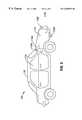
- FIG. 3is a vehicle with a fuel cell system and air purification subsystem according to an embodiment of the invention.
- FIG. 4is a schematic diagram of a fuel cell system that may be used in accordance with the present invention.
- FIG. 5is an exploded view of an air purification subsystem according to an embodiment of the invention.
- FIG. 6is an air purification subsystem according to an embodiment of the invention.
- an embodiment of an air circulation system 10includes a fuel cell system 14 that supplies electrical power (via electrical lines 16 ) to a building having an air space 12 and purifies the air in the air space 12 .
- the air spacemay be the interior air space of a building, such as a home or office building, or as another example, the interior air space of a vehicle.
- the air spacemay also have a vent 6 , for example to vent to the atmosphere. It will also be appreciated that where the fuel cell system 14 is vented to the atmosphere, for example, through line 4 , the present invention may also be used to purify the ambient air around the fuel cell system 14 , as fed to the fuel cell for example through line 2 .
- the fuel cell system 14may include a fuel cell stack 50 that consumes both oxygen and hydrogen to produce the electrical power.
- the oxygenmay be taken, for example from the air around the fuel cell system 14 , or from the interior air space 12 .
- the hydrogenmay be provided, for example, from a natural gas reformer (not shown) in the fuel cell system 14 .
- the hydrogenmay be provided from hydrogen tanks or other hydrogen storage systems such as hydrogen storage alloys.
- airis drawn into the fuel cell stack 50 through cathode inlet conduit 18 .
- the airpasses over the fuel cell cathode (not shown), and passes out of the stack 50 as cathode exhaust through cathode outlet conduit 20 .
- the air purification subsystemconsists of the modifications made to the cathode to optimize its air purification capabilities over what would normally be required just for fuel cell operation (see discussion below).
- the stream of airpasses across the modified cathode of each fuel cell of the stack 50 , and as a result, the air flowing through the fuel cells is purified, for example as pollutants are oxidized.
- the fuel cell system 14may provide dual functions: a power function in which the fuel cell system 14 supplies electrical power and an air purification function in which the fuel cell system 14 purifies the air in the air space 12 .
- the fuel cell system 14may reside outside of the air space 12 and may be connected into an air circulation path with an interior region of the air space 12 via an cathode inlet conduit 18 and a cathode outlet conduit 20 .
- the cathode inlet conduit 18may receive air from the interior region of the air space 12 and direct a stream of air into the fuel cell system 14 .
- the fuel cell system 14uses oxygen from the stream of air to promote the cathodic reactions of its fuel cells.
- the catalysts of the fuel cellsproduce a purified stream of air that is routed through the cathode outlet conduit 20 to a region inside the air space 12 .
- the cathode outlet conduit 20may be connected to an air intake return duct 24 for a climate control unit 22 of a climate control system of the air space 12 .
- the climate control systemmay maintain the interior of the air space 12 at a specified climate, such as a specified temperature and/or humidity.
- the climate control unit 22may be an interior unit of an air conditioning system, a heating system, a humidifying system or a dehumidifying system, as just a few examples.
- the purified airmay be injected into the return duct 24 to be heated, cooled, humidified or dehumidified by the climate control unit 22 before exiting an output duct 26 of the climate control unit 22 to propagate throughout the air space 12 through additional ducts (not shown).
- the climate control unit 22may be located within air space 12 , or may also be located within fuel cell system 14 .
- ducts and conduitsare used interchangeably to refer to the way the cathode flow path of the fuel cell system 14 is connected, for example to air space 12 .
- the inventionis not limited according to the means by which the cathode flow path is connected.
- the cathode exhaust of the fuel cell system 14will be at about the same temperature as the fuel cell stack 50 , for example, an operating temperature in the range of 60° C. to 200° C.
- the heat from the fuel cell stack 50may be used to efficiently provide air that is not only purified, but also pre-heated.
- the cathode inletmight instead be taken from the outside air around the fuel cell system 14 to preserve the cool air in the air space 12 , and similarly the cathode exhaust might be vented to the atmosphere.
- the purification fumction of the fuel cell system 14would be directed to the atmosphere around the fuel cell system 14 .
- an embodiment of an air circulation system 100includes a fuel cell system 114 that supplies electrical power to a vehicle 130 , for example to propel the vehicle 130 , and also provides purified air to the air space 112 A of the vehicle 130 .
- the fuel cell system 114may draw oxygen, for example from the air space within the vehicle 112 A through cathode inlet conduit 118 A, or from the air space outside the vehicle 112 B through cathode inlet conduit 118 B.
- the air passing through the fuel cell system 114is purified, and may be flowed into the vehicle air space 112 A through cathode outlet conduit 120 A, or may be vented to the atmosphere around the vehicle 112 B through cathode outlet conduit 120 B.
- the fuel cell system 114 of vehicle 130may be used to clean pollutants from the air space outside the vehicle 130 as the vehicle is driven and air from air space 112 B circulates through the fuel cell system 114 .
- a vehicle 130could provide the advantage of removing more pollutants from the air 112 B than produced by the vehicle 130 , and thus could be referred to as a sub-zero emission vehicle.
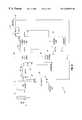
- FIG. 4depicts one of many possible embodiments of the fuel cell system 14 .
- the fuel cell system 14may include a particulate filter 74 that is connected to the cathode inlet conduit 18 to filter particles from the incoming air before the air reaches an air blower 72 .
- the air blower 72may be controlled by an electrical control unit 68 (via one or more electrical control lines 69 , for example) to regulate a rate at which the air flows from the blower 72 through an air conduit 52 into control valves 56 .
- the rate of air flow out of the air blower 72may be dependent on the output power (as indicated by an output current, for example) that is currently being provided by the fuel cell system 14 .
- the control valves 56Through a fuel input conduit 54 , the control valves 56 also receive hydrogen (the fuel). The control valves 56 maintain the appropriate flow rates of the hydrogen and air into respective conduits 58 and 60 that direct the hydrogen and air into the fuel cell stack 50 .
- the fuel cell system 14may include an air control valve 78 that is coupled between the cathode outlet conduit 20 and a conduit 62 that is connected to an air exhaust port of the fuel cell stack 50 .
- the electrical control unit 68may regulate the valve 78 to control when the purified air exits the fuel cell system 14 and enters the air space 12 .
- the climate control unit 22(see FIG. 2) during its normal course of operation may turn on and off (turn its air blower on and off, for example) as needed to regulate the climate of the air space 12 .
- the control unit 68may be electrically coupled to the climate control unit 22 to receive a signal from the climate control unit 22 to indicate whether the blower of the unit 22 is turned on (i.e., the climate control unit 22 is turned on) or off (i.e., the climate control unit is turned off.
- control unit 68may be coupled to a sensor 21 that is positioned inside the cathode outlet conduit 20 . Due to this arrangement, the control unit 68 may use the sensor 21 to determine when the climate control unit 22 has its blower turned on.
- the sensor 21may be an acoustic sensor that the control unit 68 uses to recognize an acoustic signature (that propagates through the duct work) to indicate that the blower of the climate control unit 22 has been turned on.
- the sensor 21may be, for example, a pressure sensor to detect a slight vacuum that indicates the climate control unit's blower has been turned on. Other arrangements are possible.
- a power conditioning circuit 64may receive a DC voltage from the fuel cell stack 50 and furnish to the electrical lines 16 one or more AC voltages.
- the fuel cell system 14may also include a water humidification system 66 to vaporize deionized water and circulate the vapor through the fuel cell stack 50 to humidify the air and hydrogen. In this manner, the humidified air and hydrogen keep membranes of the fuel cell stack 50 from drying out.
- a reformer 70may receive propane or natural gas (as examples) and convert the gas into the hydrogen fuel that is consumed by the fuel cell stack 50 .
- the valve 78when the air control valve 78 blocks communication between the conduits 62 and 20 , the valve 78 establishes communication between the conduit 62 and a conduit 76 that is connected to the reformer 70 .
- the purified airmay be used to, as an example, oxidize carbon monoxide (CO) that is a byproduct of the reactions that occur in the reformer 70 .
- cathode exhaustmay be significantly concentrated in carbon dioxide and saturated with humidity.
- Such an exhaust streammay be used as generally shown in FIGS. 1 and 2 to provide an ideal air feed system for a greenhouse or other agricultural applications, since the utilization of both moisture and carbon dioxide is generally essential to plant life.
- cathode airmight be taken from outside a greenhouse (to provide normal amounts of oxygen to the fuel cell), and then the humid cathode exhaust could be supplied to a greenhouse.
- the carbon dioxide rich anode exhaustcould also be supplied to the greenhouse.
- the cathode outlet conduit 18might be equipped with an oxygen sensor to control the cathode flow rate at a level corresponding to an acceptable level of oxygen depletion (less than 5% or 2% as examples). It will be appreciated that a higher cathode flow rate may tend to lower the operating temperature of the fuel cell stack 50 .
- a cooling subsystem(not shown) of the fuel cell system 14 may be responsive to the above cathode flow modulations to control or optimize the operating temperature of the stack 50 .
- housing 210has an inlet 220 , an outlet 230 , and a central portion 240 housing a catalytic monolith 250 .
- the subsystem 200could be located, for example, in the cathode flow path of a fuel cell system (not shown) immediately downstream from a fuel cell stack, so that inlet 220 receives cathode exhaust from the fuel cell stack.
- the exhaustis then passed through monolith 250 , which due to heating from the cathode exhaust passing through it (as an example), is at a temperature corresponding to the operation temperature of the fuel cell stack (e.g., about 80-200° C., depending on the particular system).
- Monolith 250can be a ceramic or zeolite substrate 260 coated with a catalyst 270 suitable for oxidizing carbon monoxide at the temperature of the fuel cell stack.
- the housing 210 and its contentsmay be generally referred to as a catalyst bed, though the term catalyst bed may also refer to other configuration, such as non-monolith arrangements (e.g., catalyst coated ceramic spheres, etc.).
- the catalyst 270can be, for example, a platinum based material such as the Premair® catalyst available from Engelhard Corporation.
- the catalyst 270can be pure platinum, or platinum alloys asknown in the art for oxidizing carbon monoxide. Such materials may also be selected specifically to optimize the reaction of ozone from the cathode-stream.
- the catalyst 270can comprise a cement carrier including activated carbon and an alkali, the cement being impregnated with palladium or a palladium alloy.
- a cement carrier including activated carbon and an alkalisuch as Maki, et al., U.S. Pat. No. 4,212,854, which is hereby incorporated by reference.
- Another possible catalyst arrangement suitable for temperatures above about 80° C.is a hopcalite type catalyst consisting of manganese dioxide mixed with the oxide of a metal such as copper, iron, cobalt or silver.
- Another possible catalyst arrangementis a tin (IV) oxide support with a thin precious metal layer as taught by Wright, et al., U.S. Pat. No. 4,524,051, which is hereby incorporated by reference.
- Another possible catalyst arrangementis an A type zeolite impregnated with the cathode stream.
- a ceramic honeycomb monolith containing MnO 2 , NiO, CuO, or Ag 2 Omay be used as noted in Yoshimoto, et al., U.S. Pat. Nos. 5,212,140 and 5,221,649, which are hereby incorporated by reference.
- Discussion of the utilization of various ozone catalyst systems, both new and well known arrangementsis provided in Galligan, et al., U.S. Pat. No. 5,620,672, Campbell, et al., U.S. Pat. No. 5,888,924, and Sassa, et al., U.S. Pat. No. 5,891,402, which are also hereby incorporated by reference.
- FIG. 6another air purification subsystem 300 is shown that could be used in an embodiment of the invention.
- PEM fuel cellstypically utilize a five layer configuration consisting of a polymeric membrane 310 having a catalyst layer 320 on either side, the catalyst layer being further enclosed by gas diffusion layers 330 on either side.
- Membrane 310is a solid polymer (e.g., a solid polymer ion exchange membrane), such as a solid polymer proton exchange membrane (e.g., a solid polymer containing sulfonic acid groups).
- solid polymere.g., a solid polymer ion exchange membrane
- Such membranesare commercially available from E.I. DuPont de Nemours Company (Wilmington, Del.) under the trademark NAFION.
- membrane 310can also be prepared from the commercial product GORE-SELECT, available from W.L. Gore & Associates (Elkton, Md.).
- the membranemay be made from a polybenimidazole material, such as taught by Onorato, et al., U.S. Pat. No. 5,945,233, which is hereby incorporated by reference.
- Catalyst layers 320can include, as examples, platinum, platinum alloys, platinum dispersed on carbon black, and other materials known in the art.
- gas diffusion layers 330can be formed of porous conductive materials such as carbon paper or carbon cloth.
- Air purification catalyst layer 360may consist of the catalyst materials described with respect to FIG. 5 . While in the embodiment shown in FIG. 6, the catalyst layer 360 is shown as an external layer to gas diffusion layer 330 , it will be appreciated that catalyst layer 360 may also be applied as an additional layer to fuel cell catalyst layer 320 . Alternatively, layer 360 may be combined into layer 320 to achieve multiple functions from the same catalyst.
Landscapes
- Chemical & Material Sciences (AREA)
- Chemical Kinetics & Catalysis (AREA)
- Electrochemistry (AREA)
- General Chemical & Material Sciences (AREA)
- Life Sciences & Earth Sciences (AREA)
- Engineering & Computer Science (AREA)
- Manufacturing & Machinery (AREA)
- Sustainable Development (AREA)
- Sustainable Energy (AREA)
- Fuel Cell (AREA)
Abstract
Description
Claims (22)
Priority Applications (1)
| Application Number | Priority Date | Filing Date | Title |
|---|---|---|---|
| US09/443,229US6489052B1 (en) | 1999-11-18 | 1999-11-18 | Fuel cell air purification subsystem |
Applications Claiming Priority (1)
| Application Number | Priority Date | Filing Date | Title |
|---|---|---|---|
| US09/443,229US6489052B1 (en) | 1999-11-18 | 1999-11-18 | Fuel cell air purification subsystem |
Publications (1)
| Publication Number | Publication Date |
|---|---|
| US6489052B1true US6489052B1 (en) | 2002-12-03 |
Family
ID=23759933
Family Applications (1)
| Application Number | Title | Priority Date | Filing Date |
|---|---|---|---|
| US09/443,229Expired - LifetimeUS6489052B1 (en) | 1999-11-18 | 1999-11-18 | Fuel cell air purification subsystem |
Country Status (1)
| Country | Link |
|---|---|
| US (1) | US6489052B1 (en) |
Cited By (36)
| Publication number | Priority date | Publication date | Assignee | Title |
|---|---|---|---|---|
| US20030096152A1 (en)* | 2001-10-31 | 2003-05-22 | Plug Power Inc. | Fuel cell air system and method |
| US20040058215A1 (en)* | 2000-12-29 | 2004-03-25 | Brueck Rolf | Fuel cell system for mobile applications with latent heat storage, and method for thermally insulating the fuel cell system |
| US20040157095A1 (en)* | 2000-12-29 | 2004-08-12 | Rolf Bruck | Method for operating a fuel cell system which can be used in a vehicle, and associated fuel cell system |
| US6797421B2 (en)* | 2002-01-11 | 2004-09-28 | Utc Fuel Cells, Llc | Method and apparatus for preventing water in fuel cell power plants from freezing during storage |
| US20040247968A1 (en)* | 2003-06-05 | 2004-12-09 | Frank Brenner | Fuel cell with cooling system |
| US20040261616A1 (en)* | 2003-06-26 | 2004-12-30 | Jorgensen Betty S. | Cross-linked polybenzimidazole membrane for gas separation |
| US20060021502A1 (en)* | 2004-07-28 | 2006-02-02 | Young Jennifer S | Cross-linked polybenzimidazole membrane for gas separation |
| US7226461B2 (en) | 2002-04-19 | 2007-06-05 | Pelikan Technologies, Inc. | Method and apparatus for a multi-use body fluid sampling device with sterility barrier release |
| US7258693B2 (en) | 2002-04-19 | 2007-08-21 | Pelikan Technologies, Inc. | Device and method for variable speed lancet |
| WO2006122169A3 (en)* | 2005-05-10 | 2007-10-18 | Ogenix Corp | Novel portable electrochemical devices for dual action wound healing |
| US7297151B2 (en) | 2002-04-19 | 2007-11-20 | Elikan Technologies, Inc. | Method and apparatus for body fluid sampling with improved sensing |
| US20070299444A1 (en)* | 2004-08-26 | 2007-12-27 | Endius, Inc. | Methods and apparatus for access to and/or treatment of the spine |
| US7316700B2 (en) | 2001-06-12 | 2008-01-08 | Pelikan Technologies, Inc. | Self optimizing lancing device with adaptation means to temporal variations in cutaneous properties |
| US7331931B2 (en) | 2002-04-19 | 2008-02-19 | Pelikan Technologies, Inc. | Method and apparatus for penetrating tissue |
| US7344894B2 (en) | 2001-10-16 | 2008-03-18 | Agilent Technologies, Inc. | Thermal regulation of fluidic samples within a diagnostic cartridge |
| EP1926166A1 (en)* | 2006-11-22 | 2008-05-28 | Vaillant GmbH | Fuel cell heating device |
| US7537571B2 (en) | 2001-06-12 | 2009-05-26 | Pelikan Technologies, Inc. | Integrated blood sampling analysis system with multi-use sampling module |
| US7674232B2 (en) | 2002-04-19 | 2010-03-09 | Pelikan Technologies, Inc. | Method and apparatus for penetrating tissue |
| US7682318B2 (en) | 2001-06-12 | 2010-03-23 | Pelikan Technologies, Inc. | Blood sampling apparatus and method |
| US7704918B2 (en) | 2005-05-19 | 2010-04-27 | Brookhaven Science Associates, Llc | Synthesis of metal-metal oxide catalysts and electrocatalysts using a metal cation adsorption/reduction and adatom replacement by more noble ones |
| US20100203427A1 (en)* | 2005-09-21 | 2010-08-12 | Hiroyuki Hasebe | Fuel cell |
| US7909775B2 (en) | 2001-06-12 | 2011-03-22 | Pelikan Technologies, Inc. | Method and apparatus for lancet launching device integrated onto a blood-sampling cartridge |
| US20120122016A1 (en)* | 2010-11-15 | 2012-05-17 | Gm Global Technology Operations, Inc. | Fuel Cell Durability Through Oxide Supported Precious Metals in Membrane |
| US8216154B2 (en) | 2001-06-12 | 2012-07-10 | Sanofi-Aventis Deutschland Gmbh | Tissue penetration device |
| US8251921B2 (en) | 2003-06-06 | 2012-08-28 | Sanofi-Aventis Deutschland Gmbh | Method and apparatus for body fluid sampling and analyte sensing |
| US8491500B2 (en) | 2002-04-19 | 2013-07-23 | Sanofi-Aventis Deutschland Gmbh | Methods and apparatus for lancet actuation |
| US8965476B2 (en) | 2010-04-16 | 2015-02-24 | Sanofi-Aventis Deutschland Gmbh | Tissue penetration device |
| US20150188171A1 (en)* | 2012-06-29 | 2015-07-02 | Mag Aerospace Industries, Llc | Microbiologically protected fuel cell |
| US9386944B2 (en) | 2008-04-11 | 2016-07-12 | Sanofi-Aventis Deutschland Gmbh | Method and apparatus for analyte detecting device |
| US9776121B2 (en) | 2013-05-17 | 2017-10-03 | Mann+Hummel Gmbh | Filter element, particularly air filter element, and filter system having a filter element |
| US9795747B2 (en) | 2010-06-02 | 2017-10-24 | Sanofi-Aventis Deutschland Gmbh | Methods and apparatus for lancet actuation |
| US9820684B2 (en) | 2004-06-03 | 2017-11-21 | Sanofi-Aventis Deutschland Gmbh | Method and apparatus for a fluid sampling device |
| US9907502B2 (en) | 2002-04-19 | 2018-03-06 | Sanofi-Aventis Deutschland Gmbh | Method and apparatus for penetrating tissue |
| US9972849B2 (en) | 2009-09-24 | 2018-05-15 | Kabushiki Kaisha Toshiba | Collector member, power generator, and method of manufacturing collector member for power generator |
| US11344640B2 (en)* | 2018-04-18 | 2022-05-31 | Anderson Industries, Llc | Portable sterilization and decontamination system |
| JP2023526425A (en)* | 2020-05-22 | 2023-06-21 | ヌマット テクノロジーズ,インコーポレイテッド | Method for refining hydrogen gas used in fuel cells |
Citations (15)
| Publication number | Priority date | Publication date | Assignee | Title |
|---|---|---|---|---|
| US4212854A (en) | 1977-03-18 | 1980-07-15 | Matsushita Electric Industrial Co., Ltd. | Method for purification of air containing carbon monoxide |
| US4524051A (en) | 1983-01-10 | 1985-06-18 | United Kingdom Atomic Energy Authority | Catalyst preparation and oxidation of carbon monoxide with said catalyst |
| US5212140A (en) | 1991-02-28 | 1993-05-18 | Sakai Chemical Industry Co., Inc. | Catalyst for decomposing ozone |
| US5221649A (en) | 1988-11-28 | 1993-06-22 | Sakai Chemical Industry Co., Ltd. | Catalysts and methods for ozone decomposition |
| US5330857A (en)* | 1991-10-30 | 1994-07-19 | International Fuel Cells Corporation | Method of generating high-purity nitrogen gas |
| US5436086A (en)* | 1992-11-11 | 1995-07-25 | Vickers Shipbuilding & Engineering Limited | Processing of fuel gases, in particular for fuel cells and apparatus therefor |
| US5595949A (en)* | 1994-03-18 | 1997-01-21 | Electric Fuel (E.F.L.) Ltd., | Scrubber system for removing carbon dioxide from a metal-air or fuel cell battery |
| US5620672A (en) | 1994-02-25 | 1997-04-15 | Engelhard Corporation | Layered catalyst composition |
| US5658681A (en) | 1994-09-30 | 1997-08-19 | Kabushikikaisha Equos Research | Fuel cell power generation system |
| US5702838A (en) | 1995-08-18 | 1997-12-30 | Matsushita Electric Industrial Co., Ltd. | Fuel cell device equipped with catalyst material for removing carbon monoxide and method for removing carbon monoxide |
| US5888924A (en) | 1996-08-07 | 1999-03-30 | Goal Line Enviromental Technologies Llc | Pollutant removal from air in closed spaces |
| US5891402A (en) | 1994-03-02 | 1999-04-06 | W. L. Gore & Associates, Inc. | Catalyst retaining apparatus and use in an ozone filter |
| US5900222A (en) | 1993-12-31 | 1999-05-04 | Technische Universiteit Delft | Process for treating nitrogen oxide-containing gas using a cerium zeolite |
| US6124054A (en)* | 1998-12-23 | 2000-09-26 | International Fuel Cells, Llc | Purged anode low effluent fuel cell |
| US6276473B1 (en)* | 1999-03-26 | 2001-08-21 | Xcellsis Gmbh | Hybrid vehicle having a an internal-combustion engine, a fuel cell system and an electric drive motor |
- 1999
- 1999-11-18USUS09/443,229patent/US6489052B1/ennot_activeExpired - Lifetime
Patent Citations (15)
| Publication number | Priority date | Publication date | Assignee | Title |
|---|---|---|---|---|
| US4212854A (en) | 1977-03-18 | 1980-07-15 | Matsushita Electric Industrial Co., Ltd. | Method for purification of air containing carbon monoxide |
| US4524051A (en) | 1983-01-10 | 1985-06-18 | United Kingdom Atomic Energy Authority | Catalyst preparation and oxidation of carbon monoxide with said catalyst |
| US5221649A (en) | 1988-11-28 | 1993-06-22 | Sakai Chemical Industry Co., Ltd. | Catalysts and methods for ozone decomposition |
| US5212140A (en) | 1991-02-28 | 1993-05-18 | Sakai Chemical Industry Co., Inc. | Catalyst for decomposing ozone |
| US5330857A (en)* | 1991-10-30 | 1994-07-19 | International Fuel Cells Corporation | Method of generating high-purity nitrogen gas |
| US5436086A (en)* | 1992-11-11 | 1995-07-25 | Vickers Shipbuilding & Engineering Limited | Processing of fuel gases, in particular for fuel cells and apparatus therefor |
| US5900222A (en) | 1993-12-31 | 1999-05-04 | Technische Universiteit Delft | Process for treating nitrogen oxide-containing gas using a cerium zeolite |
| US5620672A (en) | 1994-02-25 | 1997-04-15 | Engelhard Corporation | Layered catalyst composition |
| US5891402A (en) | 1994-03-02 | 1999-04-06 | W. L. Gore & Associates, Inc. | Catalyst retaining apparatus and use in an ozone filter |
| US5595949A (en)* | 1994-03-18 | 1997-01-21 | Electric Fuel (E.F.L.) Ltd., | Scrubber system for removing carbon dioxide from a metal-air or fuel cell battery |
| US5658681A (en) | 1994-09-30 | 1997-08-19 | Kabushikikaisha Equos Research | Fuel cell power generation system |
| US5702838A (en) | 1995-08-18 | 1997-12-30 | Matsushita Electric Industrial Co., Ltd. | Fuel cell device equipped with catalyst material for removing carbon monoxide and method for removing carbon monoxide |
| US5888924A (en) | 1996-08-07 | 1999-03-30 | Goal Line Enviromental Technologies Llc | Pollutant removal from air in closed spaces |
| US6124054A (en)* | 1998-12-23 | 2000-09-26 | International Fuel Cells, Llc | Purged anode low effluent fuel cell |
| US6276473B1 (en)* | 1999-03-26 | 2001-08-21 | Xcellsis Gmbh | Hybrid vehicle having a an internal-combustion engine, a fuel cell system and an electric drive motor |
Non-Patent Citations (1)
| Title |
|---|
| Internet Printout. http://www.justcatalyticconverters.co.uk/technic.htm, Oct. 2001.* |
Cited By (49)
| Publication number | Priority date | Publication date | Assignee | Title |
|---|---|---|---|---|
| US20040058215A1 (en)* | 2000-12-29 | 2004-03-25 | Brueck Rolf | Fuel cell system for mobile applications with latent heat storage, and method for thermally insulating the fuel cell system |
| US20040157095A1 (en)* | 2000-12-29 | 2004-08-12 | Rolf Bruck | Method for operating a fuel cell system which can be used in a vehicle, and associated fuel cell system |
| US9937298B2 (en) | 2001-06-12 | 2018-04-10 | Sanofi-Aventis Deutschland Gmbh | Tissue penetration device |
| US8216154B2 (en) | 2001-06-12 | 2012-07-10 | Sanofi-Aventis Deutschland Gmbh | Tissue penetration device |
| US7316700B2 (en) | 2001-06-12 | 2008-01-08 | Pelikan Technologies, Inc. | Self optimizing lancing device with adaptation means to temporal variations in cutaneous properties |
| US7909775B2 (en) | 2001-06-12 | 2011-03-22 | Pelikan Technologies, Inc. | Method and apparatus for lancet launching device integrated onto a blood-sampling cartridge |
| US7682318B2 (en) | 2001-06-12 | 2010-03-23 | Pelikan Technologies, Inc. | Blood sampling apparatus and method |
| US7537571B2 (en) | 2001-06-12 | 2009-05-26 | Pelikan Technologies, Inc. | Integrated blood sampling analysis system with multi-use sampling module |
| US7344894B2 (en) | 2001-10-16 | 2008-03-18 | Agilent Technologies, Inc. | Thermal regulation of fluidic samples within a diagnostic cartridge |
| US7122258B2 (en)* | 2001-10-31 | 2006-10-17 | Plug Power Inc. | Fuel cell air system and method |
| US20030096152A1 (en)* | 2001-10-31 | 2003-05-22 | Plug Power Inc. | Fuel cell air system and method |
| WO2003061031A3 (en)* | 2002-01-11 | 2005-09-15 | Utc Fuel Cells Llc | Method and apparatus for preventing water in fuel cell power plants from freezing during storage |
| KR100943626B1 (en)* | 2002-01-11 | 2010-02-24 | 유티씨 파워 코포레이션 | Method and apparatus for preventing freezing of water in fuel cell power units during storage |
| US6797421B2 (en)* | 2002-01-11 | 2004-09-28 | Utc Fuel Cells, Llc | Method and apparatus for preventing water in fuel cell power plants from freezing during storage |
| US7226461B2 (en) | 2002-04-19 | 2007-06-05 | Pelikan Technologies, Inc. | Method and apparatus for a multi-use body fluid sampling device with sterility barrier release |
| US8491500B2 (en) | 2002-04-19 | 2013-07-23 | Sanofi-Aventis Deutschland Gmbh | Methods and apparatus for lancet actuation |
| US7875047B2 (en) | 2002-04-19 | 2011-01-25 | Pelikan Technologies, Inc. | Method and apparatus for a multi-use body fluid sampling device with sterility barrier release |
| US7297151B2 (en) | 2002-04-19 | 2007-11-20 | Elikan Technologies, Inc. | Method and apparatus for body fluid sampling with improved sensing |
| US7331931B2 (en) | 2002-04-19 | 2008-02-19 | Pelikan Technologies, Inc. | Method and apparatus for penetrating tissue |
| US7258693B2 (en) | 2002-04-19 | 2007-08-21 | Pelikan Technologies, Inc. | Device and method for variable speed lancet |
| US8562545B2 (en) | 2002-04-19 | 2013-10-22 | Sanofi-Aventis Deutschland Gmbh | Tissue penetration device |
| US7674232B2 (en) | 2002-04-19 | 2010-03-09 | Pelikan Technologies, Inc. | Method and apparatus for penetrating tissue |
| US9907502B2 (en) | 2002-04-19 | 2018-03-06 | Sanofi-Aventis Deutschland Gmbh | Method and apparatus for penetrating tissue |
| US20040247968A1 (en)* | 2003-06-05 | 2004-12-09 | Frank Brenner | Fuel cell with cooling system |
| US8251921B2 (en) | 2003-06-06 | 2012-08-28 | Sanofi-Aventis Deutschland Gmbh | Method and apparatus for body fluid sampling and analyte sensing |
| US6946015B2 (en)* | 2003-06-26 | 2005-09-20 | The Regents Of The University Of California | Cross-linked polybenzimidazole membrane for gas separation |
| US20040261616A1 (en)* | 2003-06-26 | 2004-12-30 | Jorgensen Betty S. | Cross-linked polybenzimidazole membrane for gas separation |
| US9820684B2 (en) | 2004-06-03 | 2017-11-21 | Sanofi-Aventis Deutschland Gmbh | Method and apparatus for a fluid sampling device |
| US6997971B1 (en)* | 2004-07-28 | 2006-02-14 | The Regents Of The University Of California | Cross-linked polybenzimidazole membrane for gas separation |
| WO2006028594A3 (en)* | 2004-07-28 | 2006-05-04 | Univ California | Cross-linked polybenzimidazole membrane for gas separation |
| US20060021502A1 (en)* | 2004-07-28 | 2006-02-02 | Young Jennifer S | Cross-linked polybenzimidazole membrane for gas separation |
| US20070299444A1 (en)* | 2004-08-26 | 2007-12-27 | Endius, Inc. | Methods and apparatus for access to and/or treatment of the spine |
| KR101278461B1 (en) | 2005-05-10 | 2013-07-02 | 오제닉스 코퍼레이션 | Novel portable electrochemical devices for dual action wound healing |
| WO2006122169A3 (en)* | 2005-05-10 | 2007-10-18 | Ogenix Corp | Novel portable electrochemical devices for dual action wound healing |
| US7704918B2 (en) | 2005-05-19 | 2010-04-27 | Brookhaven Science Associates, Llc | Synthesis of metal-metal oxide catalysts and electrocatalysts using a metal cation adsorption/reduction and adatom replacement by more noble ones |
| US8308989B2 (en) | 2005-05-19 | 2012-11-13 | Brookhaven Science Associates, Llc | Electrocatalyst for oxygen reduction with reduced platinum oxidation and dissolution rates |
| US20110151356A1 (en)* | 2005-05-19 | 2011-06-23 | Brookhaven Science Associates, Llc | Electrocatalyst for Oxygen Reduction with Reduced Platinum Oxidation and Dissolution Rates |
| US8062552B2 (en) | 2005-05-19 | 2011-11-22 | Brookhaven Science Associates, Llc | Electrocatalyst for oxygen reduction with reduced platinum oxidation and dissolution rates |
| US20100203427A1 (en)* | 2005-09-21 | 2010-08-12 | Hiroyuki Hasebe | Fuel cell |
| EP1926166A1 (en)* | 2006-11-22 | 2008-05-28 | Vaillant GmbH | Fuel cell heating device |
| US9386944B2 (en) | 2008-04-11 | 2016-07-12 | Sanofi-Aventis Deutschland Gmbh | Method and apparatus for analyte detecting device |
| US9972849B2 (en) | 2009-09-24 | 2018-05-15 | Kabushiki Kaisha Toshiba | Collector member, power generator, and method of manufacturing collector member for power generator |
| US8965476B2 (en) | 2010-04-16 | 2015-02-24 | Sanofi-Aventis Deutschland Gmbh | Tissue penetration device |
| US9795747B2 (en) | 2010-06-02 | 2017-10-24 | Sanofi-Aventis Deutschland Gmbh | Methods and apparatus for lancet actuation |
| US20120122016A1 (en)* | 2010-11-15 | 2012-05-17 | Gm Global Technology Operations, Inc. | Fuel Cell Durability Through Oxide Supported Precious Metals in Membrane |
| US20150188171A1 (en)* | 2012-06-29 | 2015-07-02 | Mag Aerospace Industries, Llc | Microbiologically protected fuel cell |
| US9776121B2 (en) | 2013-05-17 | 2017-10-03 | Mann+Hummel Gmbh | Filter element, particularly air filter element, and filter system having a filter element |
| US11344640B2 (en)* | 2018-04-18 | 2022-05-31 | Anderson Industries, Llc | Portable sterilization and decontamination system |
| JP2023526425A (en)* | 2020-05-22 | 2023-06-21 | ヌマット テクノロジーズ,インコーポレイテッド | Method for refining hydrogen gas used in fuel cells |
Similar Documents
| Publication | Publication Date | Title |
|---|---|---|
| US6489052B1 (en) | Fuel cell air purification subsystem | |
| US6284399B1 (en) | Fuel cell system having humidification membranes | |
| AU2001268867B2 (en) | Water recovery in the anode side of a proton exchange membrane fuel cell | |
| US6451466B1 (en) | Functional integration of multiple components for a fuel cell power plant | |
| US5200278A (en) | Integrated fuel cell power generation system | |
| US8206864B2 (en) | Fuel cell stacks and systems with fluid-responsive temperature regulation | |
| US20080026270A1 (en) | Fuel cell and apparatus for purifying air supplied to fuel cell | |
| US20060199061A1 (en) | Water management in bipolar electrochemical cell stacks | |
| US6706429B1 (en) | Catalytic humidifier and heater, primarily for humidification of the oxidant stream for a fuel cell | |
| US20090068512A1 (en) | Hydrogen refueling station | |
| US20080299423A1 (en) | Fuel cell systems with maintenance hydration | |
| US6896792B2 (en) | Method and device for improved catalytic activity in the purification of fluids | |
| US6605378B2 (en) | Functional integration of multiple components for a fuel cell power plant | |
| US20040197616A1 (en) | Oxidant-enriched fuel cell system | |
| CN100407490C (en) | Fuel cell system | |
| CN100428550C (en) | Fuel cell, oxidant flow field plate for fuel cell | |
| US20230006223A1 (en) | Methods and Apparatus for Mold Mitigation in Fuel Cell Humidifiers | |
| JP4028320B2 (en) | Fuel circulation fuel cell system | |
| US7267901B2 (en) | Fuel cell system | |
| US20050074640A1 (en) | Fuel cell system and operation method thereof | |
| US20020164521A1 (en) | Novel applications of exfoliated transition metal dichalcogenides to electrochemical fuel cells | |
| US6913846B2 (en) | Integrated fuel cell system | |
| JPH06267562A (en) | Solid high polymer electrolyte fuel cell | |
| WO2004062016A1 (en) | Hydrogen gas humidity controller, fuel cell, hydrogen gas humidity controlling method, and humidity controlling method of fuel cell | |
| US10403918B2 (en) | Heated catalytic oxidizer for an enclosed humid environment |
Legal Events
| Date | Code | Title | Description |
|---|---|---|---|
| AS | Assignment | Owner name:PLUG POWER, INC., NEW YORK Free format text:ASSIGNMENT OF ASSIGNORS INTEREST;ASSIGNOR:ACKER, WILLIAM P.;REEL/FRAME:010398/0228 Effective date:19991112 | |
| STCF | Information on status: patent grant | Free format text:PATENTED CASE | |
| CC | Certificate of correction | ||
| FPAY | Fee payment | Year of fee payment:4 | |
| FPAY | Fee payment | Year of fee payment:8 | |
| FEPP | Fee payment procedure | Free format text:PAYOR NUMBER ASSIGNED (ORIGINAL EVENT CODE: ASPN); ENTITY STATUS OF PATENT OWNER: SMALL ENTITY | |
| REMI | Maintenance fee reminder mailed | ||
| FPAY | Fee payment | Year of fee payment:12 | |
| SULP | Surcharge for late payment | Year of fee payment:11 | |
| AS | Assignment | Owner name:GENERATE LENDING, LLC, CALIFORNIA Free format text:SECURITY INTEREST;ASSIGNOR:PLUG POWER INC.;REEL/FRAME:038463/0132 Effective date:20160321 | |
| AS | Assignment | Owner name:PLUG POWER INC., NEW YORK Free format text:RELEASE BY SECURED PARTY;ASSIGNOR:GENERATE LENDING, LLC;REEL/FRAME:039173/0300 Effective date:20160627 | |
| AS | Assignment | Owner name:HERCULES CAPITAL, INC., CALIFORNIA Free format text:INTELLECTUAL PROPERTY SECURITY AGREEMENT;ASSIGNOR:PLUG POWER INC.;REEL/FRAME:039646/0065 Effective date:20160627 | |
| AS | Assignment | Owner name:EMERGENT POWER INC., WASHINGTON Free format text:RELEASE BY SECURED PARTY;ASSIGNOR:HERCULES CAPITAL, INC., AS AGENT;REEL/FRAME:041180/0709 Effective date:20161222 Owner name:EMERGING POWER INC., NEW YORK Free format text:RELEASE BY SECURED PARTY;ASSIGNOR:HERCULES CAPITAL, INC., AS AGENT;REEL/FRAME:041180/0709 Effective date:20161222 Owner name:PLUG POWER INC., NEW YORK Free format text:RELEASE BY SECURED PARTY;ASSIGNOR:HERCULES CAPITAL, INC., AS AGENT;REEL/FRAME:041180/0709 Effective date:20161222 | |
| AS | Assignment | Owner name:NY GREEN BANK, NEW YORK Free format text:SECURITY INTEREST;ASSIGNOR:PLUG POWER INC.;REEL/FRAME:041200/0623 Effective date:20161223 | |
| AS | Assignment | Owner name:GENERATE LENDING, LLC, CALIFORNIA Free format text:SECURITY INTEREST;ASSIGNORS:PLUG POWER INC.;EMERGING POWER INC.;EMERGENT POWER INC.;REEL/FRAME:048751/0396 Effective date:20190329 Owner name:EMERGENT POWER INC., WASHINGTON Free format text:RELEASE BY SECURED PARTY;ASSIGNOR:NY GREEN BANK, A DIVISION OF THE NEW YORK STATE ENERGY RESEARCH AND DEVELOPMENT AUTHORITY;REEL/FRAME:048751/0844 Effective date:20190329 Owner name:PLUG POWER INC, NEW YORK Free format text:RELEASE BY SECURED PARTY;ASSIGNOR:NY GREEN BANK, A DIVISION OF THE NEW YORK STATE ENERGY RESEARCH AND DEVELOPMENT AUTHORITY;REEL/FRAME:048751/0844 Effective date:20190329 Owner name:EMERGING POWER INC., NEW YORK Free format text:RELEASE BY SECURED PARTY;ASSIGNOR:NY GREEN BANK, A DIVISION OF THE NEW YORK STATE ENERGY RESEARCH AND DEVELOPMENT AUTHORITY;REEL/FRAME:048751/0844 Effective date:20190329 |