US6488662B2 - Percutaneous catheter assembly - Google Patents
Percutaneous catheter assemblyDownload PDFInfo
- Publication number
- US6488662B2 US6488662B2US09/741,695US74169500AUS6488662B2US 6488662 B2US6488662 B2US 6488662B2US 74169500 AUS74169500 AUS 74169500AUS 6488662 B2US6488662 B2US 6488662B2
- Authority
- US
- United States
- Prior art keywords
- dilator
- catheter housing
- catheter
- proximal end
- housing
- Prior art date
- Legal status (The legal status is an assumption and is not a legal conclusion. Google has not performed a legal analysis and makes no representation as to the accuracy of the status listed.)
- Expired - Lifetime, expires
Links
Images


Classifications
- A—HUMAN NECESSITIES
- A61—MEDICAL OR VETERINARY SCIENCE; HYGIENE
- A61M—DEVICES FOR INTRODUCING MEDIA INTO, OR ONTO, THE BODY; DEVICES FOR TRANSDUCING BODY MEDIA OR FOR TAKING MEDIA FROM THE BODY; DEVICES FOR PRODUCING OR ENDING SLEEP OR STUPOR
- A61M25/00—Catheters; Hollow probes
- A61M25/01—Introducing, guiding, advancing, emplacing or holding catheters
- A61M25/06—Body-piercing guide needles or the like
- A61M25/0662—Guide tubes
- A—HUMAN NECESSITIES
- A61—MEDICAL OR VETERINARY SCIENCE; HYGIENE
- A61M—DEVICES FOR INTRODUCING MEDIA INTO, OR ONTO, THE BODY; DEVICES FOR TRANSDUCING BODY MEDIA OR FOR TAKING MEDIA FROM THE BODY; DEVICES FOR PRODUCING OR ENDING SLEEP OR STUPOR
- A61M25/00—Catheters; Hollow probes
- A61M25/01—Introducing, guiding, advancing, emplacing or holding catheters
- A61M25/06—Body-piercing guide needles or the like
- A61M25/0606—"Over-the-needle" catheter assemblies, e.g. I.V. catheters
- A—HUMAN NECESSITIES
- A61—MEDICAL OR VETERINARY SCIENCE; HYGIENE
- A61M—DEVICES FOR INTRODUCING MEDIA INTO, OR ONTO, THE BODY; DEVICES FOR TRANSDUCING BODY MEDIA OR FOR TAKING MEDIA FROM THE BODY; DEVICES FOR PRODUCING OR ENDING SLEEP OR STUPOR
- A61M25/00—Catheters; Hollow probes
- A61M25/0067—Catheters; Hollow probes characterised by the distal end, e.g. tips
- A61M25/0068—Static characteristics of the catheter tip, e.g. shape, atraumatic tip, curved tip or tip structure
- A61M25/007—Side holes, e.g. their profiles or arrangements; Provisions to keep side holes unblocked
- A—HUMAN NECESSITIES
- A61—MEDICAL OR VETERINARY SCIENCE; HYGIENE
- A61M—DEVICES FOR INTRODUCING MEDIA INTO, OR ONTO, THE BODY; DEVICES FOR TRANSDUCING BODY MEDIA OR FOR TAKING MEDIA FROM THE BODY; DEVICES FOR PRODUCING OR ENDING SLEEP OR STUPOR
- A61M29/00—Dilators with or without means for introducing media, e.g. remedies
Definitions
- the present inventionrelates generally to a percutaneous catheter for the introduction and withdrawal of fluids from the vascular system of a patient and, more particularly, to a catheter assembly that employs a multi-diameter catheter housing, a proximal end cap for the housing having a central bore therein, and a dilator for passage through the catheter housing and the cap.
- a small slitis made in the vessel wall of a clamped vessel to permit insertion of either an arterial perfusion catheter or a therapeutic catheter for the application of, for example, an IABP.
- an atraumatic tip dilatoris positioned concentrically within the catheter over a guidewire to assist in advancing the catheter to the desired point with minimal trauma to the epithelial layer. The dilator and guidewire are then removed and the catheter left in place for treatment.
- an interventional clinicianis not trained to perform a surgical cut down to penetrate the patient's vasculature.
- a percutaneous cannulationis necessary.
- a percutaneous cannulationa very small diameter insertion needle having a hollow lumen therein is used to penetrate the vessel wall.
- a guidewireis inserted through the insertion needle, and the needle removed.
- an angio-cathwhich may be made of polyethylene, is inserted over the guidewire, replacing the needle. Where it is desired only to establish a low flow rate of fluid percutaneously, either for aspiration or infusion, the angio-cath is left in place.
- the angio-cathmay then be connected at its proximal end to a source of fluid or a syringe to inject fluid or to remove blood.
- a guide wiremay then be inserted within the lumen of the insertion needle to permit removal of the insertion needle, leaving the guide wire in place.
- an introducer sheathis inserted over the guide wire and through the vessel wall.
- a styletis placed concentrically within the introducer sheath so that both ride over the guide wire to position the sheath within the vessel wall.
- the dilatorhas a very small distal diameter to permit easy penetration through the small opening in the vessel wall.
- the dilatoris tapered with increasing diameter toward the proximal end up to the diameter of the sheath so that the opening in the vessel wall is gradually expanded.
- the dilatoris then removed, leaving the sheath within the wall with the guide wire remaining therethrough.
- the clinicianhas now established communication with the blood vessel at the desired diameter.
- the guide wireis then typically advanced into the patient's vasculature as far as is desired to either establish remote fluid communication with the patient or to a point where treatment with an perfusion catheter or other device is desired.
- a large diameter introducer sheathis required for the passage of large devices or for the passage of a large volume of blood.
- the clinicianmay exchange any one of a number of catheters without risk of losing that communication, because the sheath remains in place.
- the clinicianthreads the catheter over the guide wire to the desired location.
- the sheathmay be left in place temporarily to permit the clinician to apply treatment again without having to reopen the blood vessel wall.
- the introducer sheathhas a hemostasis valve at its proximal end to control the flow of fluid therethrough.
- a perfusion catheter of a desired sizemay be inserted over the guide wire and through the sheath.
- the guide wiremay then be removed, if so desired.
- a guiding cathetermay first be inserted within the sheath and over the guide wire while it is advanced to the desired point in the patient's vasculature.
- the guiding cathetertypically has a radiopaque marker at the distal end that may be seen through an x-ray monitor via fluoroscopy technique.
- the markertypically consists of a metallic ring detectable via fluoroscopy by the x-ray.
- radiopaque contrast fluidmay be directed through the guiding catheter and out into the vessel at the distal end to permit viewing of the vasculature through which the guiding catheter is passing. This serves the purpose of showing the general profile of the vessel as the guiding catheter is advanced. Such contrast may expose problems with continuing to proceed in that particular vessel before the guiding catheter has advanced too far.
- an intravascular devicesuch as an angioplasty balloon
- a perfusion cathetermay be inserted within the guiding catheter as well, to permit blood flow.
- the introducer sheathmay be of the type that remains in place, or it may be of the type that tears away, leaving whatever device is in the sheath to maintain the opening in the vessel wall. Once the sheath is removed, however, that device (i.e., a guiding catheter or other device) provides the only vehicle to maintain the vessel wall opening at that diameter.
- an introducer sheathpermits exchange of catheters over time without losing the benefit of an established vessel wall opening.
- the disadvantageis that it hampers the use of large diameter catheters, i.e., where it is desired to establish fluid communication with the patient's vasculature at high flow rates.
- a large diameter introducer sheathWith a large diameter introducer sheath, occlusion of the blood vessel may occur, leading to possible ischemia of the limb served by the blood vessel.
- the present inventioncomprises a percutaneous catheter assembly intended for long-term use of several days.
- the catheter assemblycomprises generally three components: a catheter housing having three sections, each of preferably differing diameter, an end cap for closing off the proximal end of the catheter housing during insertion, and a dilator having an outer diameter substantially the same size as the inner diameter of the smallest section of the catheter housing.
- the catheter housing of a preferred embodimentcomprises three sections, a distal end section, which is tapered at the tip to facilitate penetration of a vessel wall, a mid-section having an inner diameter greater than the distal section, having a tapered transition between the distal end section and the mid-section, and a proximal section having an inner diameter of preferably about 3 ⁇ 8′′ to permit connection to standard components, such as a flow probe and/or a pump.
- a polyester sleevemay be provided over the catheter housing, positioned to correspond with the point on the catheter adjacent the patient's skin. The sleeve may be sutured to the patient to resist relative movement.
- a disk surrounding the catheter housingmay be used at or about the same position on the catheter.
- a reinforcing membersuch as a helical coil, is provided in the wall of at least the distal end section and the mid-section of the catheter for reinforcement purposes.
- one or more radiopaque markersmay be positioned to assist in intravascular location during insertion of the catheter assembly. Proximate the distal tip is a plurality of openings or perforations.
- an anti-bacterial or anti-microbial coatingmay be applied to reduce infection risk
- an anti-thrombotic coatingmay be applied to reduce adhesions to the catheter housing and any other component that comes into contact with blood for any significant period of time.
- the capis configured to seal off the proximal end of the catheter housing during insertion until the proximal end of the catheter housing is ready for connection to a tube for aspiration or infusion.
- the capincludes an internal bore that has an inner diameter the same size as the dilator.
- the dilatorcomprises a long tube with a concentrically tapered distal end and a hemostasis valve at the proximal end. Extending from the hemostasis valve is a tube with a luer connector for connecting to a source of radiopaque contrast.
- the dilatorincludes a plurality of struts extending axially through the length of the dilator for stiffening the dilator.
- the distal tip of the dilatorincludes a plurality of openings, a first set positioned preferably adjacent the tip and a second set proximal thereto.
- the inventionalso comprises a preferred method of operation of the catheter assembly.
- the methodcomprises penetrating a patient's vasculature so as to permit a guide wire to be inserted in the patient's blood vessel.
- the capis placed within the proximal end of the catheter housing.
- the dilatoris then placed within the catheter housing through the cap so that the distal tip of the dilator extends just beyond the distal tip of the catheter housing. Saline is flushed through the hemostasis valve and out through the distal tip to flush the assembly of air.
- the catheter assemblyis then placed over the guide wire and inserted through the patient and into the blood vessel.
- Radiopaque contrastmay then be injected through the hemostasis valve and out through the first set of holes in the distal end of the dilator to permit detection of the distal end as the catheter assembly is being advanced through the patient.
- the radiopaque contrastalso advantageously exits the second set of holes in the distal end of the catheter so as to detect the location of the perforations in the catheter housing.
- the guide wiremay be removed. Then the dilator may then be removed, leaving the cap in place.
- a hemostatmay be used to clamp the catheter so as to prevent the flow of blood out of the proximal end of the catheter housing.
- a sleeve and/or diskmay be used to secure the catheter housing to the patient to minimize relative movement between the patient and the catheter housing. At that point, the cap may be removed and a delivery (or withdrawal) line attached to the proximal end of the catheter housing.
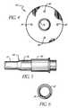
- FIG. 1is a perspective view of the present invention percutaneous catheter assembly showing its preferred components in an assembled position.
- FIG. 2is a side view of the catheter housing, the end cap, and the dilator of the assembly of FIG. 1 .
- FIG. 3is a cross-sectional view of the dilator of FIG. 2 .
- FIG. 4is a front view of the suturing disk applied to the catheter housing.
- FIG. 5is a side view of the sleeve applied to the catheter housing with internal structure shown in broken lines.
- FIG. 6is a front view of the sleeve applied to the catheter housing.
- FIG. 1shows the three main components of the assembly 10 in assembled form for application to a patient.
- the assembly 10comprises a catheter housing 12 having a single lumen therein, wherein the housing 12 has a distal end 14 and a proximal end 16 , with the distal end 14 intended to project into the vascular system of a patient.
- the assembly 10further comprises an end cap 18 configured to fit snugly within the proximal end of the catheter housing 12 to seal the housing against flow through the proximal end during use.
- the assembly 10also comprises a dilator 20 configured to protrude through the end cap 18 and through the lumen of the catheter housing 12 .
- the catheter housing 12can be described in greater detail.
- the catheter housingis made of a pliable but durable plastic material, such as urethane, although other similar materials would be acceptable.
- the catheter housing 12preferably has three sections: a distal section 22 , a mid-section 24 , and a proximal section 26 , each of different diameters.
- the distal section 22has a relatively small inner diameter of preferably about 10 French, although other sizes that would effectively pass through a blood vessel without patient trauma while permitting high blood flow would be acceptable.
- the mid-section 24has an inner diameter of preferably about 16 French, with a first tapered section 28 positioned between the distal section 22 and the mid-section 24 .
- the mid-sectionis of larger diameter than the distal section to prevent kinking of the catheter during insertion and tunneling. Sizes other than 16 French would be acceptable.
- the proximal section 26has an inner diameter of preferably 3 ⁇ 8′′ to permit connection to standard components, such as a flow probe or a pump.
- the proximal section 26is preferably configured to slip onto a barbed connector, although other connector configurations would be acceptable.
- a second tapered section 30is positioned between the mid-section 24 and the proximal section 26 . It is intended that only the distal section 22 would penetrate the patient's vascular system, with the mid-section sized to permit subcutaneous tunneling.
- the length of the distal section 22may be selected depending upon where the vessel penetration site is and where in the patient's vasculature (remote from the site) the clinician desires to establish fluid communication. For example, if the vessel penetration site were somewhere on the left femoral artery, but the fluid communication site were further up in the descending aorta, the distal section 22 would need to be sufficiently long to span that distance.
- the length of the mid-section 24may be selected depending upon where the vessel penetration site is and where the desired patient exit site is. For example, if it were desired to penetrate the left axillary artery but have the patient exit site close to the patient's waist, the mid-section 24 would need to be sufficiently long to span that distance.
- the thickness of the proximal section 26is preferably configured to permit the attachment of an external sonic based flow meter thereto.
- a tip 32 of the distal section 22is preferably tapered to facilitate penetration of a vessel wall, although it not need be tapered if so desired.
- Adjacent the distal section tip 32is a radiopaque marker 34 to assist in locating the tip of the catheter housing 12 during insertion.
- Proximate the distal tip 32is a first set of openings comprising one or more perforations 36 in the wall of the catheter housing that serve to permit peripheral distribution of a contrast fluid, i.e., radiopaque contrast, from the distal section 22 of the catheter housing 12 during insertion, as explained further below. As described further below, that peripheral distribution serves to better facilitate location and insertion of the distal end of the catheter housing 12 . Other arrangements of one or more perforations would be acceptable.
- the preferred embodiment of the catheter assembly 10further comprises an interface portion 38 that comprises a sleeve 40 comprising a synthetic material for permitting enhanced securement of the catheter assembly 10 to a patient during use.
- a sleeve 40comprising a synthetic material for permitting enhanced securement of the catheter assembly 10 to a patient during use.
- the sleeve 40comprises a third synthetic material having a textile property to enhance the use of sutures as a means for securing the catheter to the patient.
- the sleeve 40is made of polyester or other material having similar properties.
- the sleeve 40is bonded to the catheter assembly 10 in a manner to prevent relative movement between the sleeve and the catheter.
- the length of the sleeve 40may be selected as desired. The length should be sufficient, however, to give some flexibility to the physician in the placement of the catheter with respect to the exit site.
- the sleeve 40is manufactured already bonded to the catheter with a length pre-selected to give flexibility to the physician.
- the sleeve lengthmay be kept at a minimum but be manufactured discretely from the balance of the catheter, permitting, if desired, the physician to locate the sleeve where desired and then to bond the sleeve to the catheter after it is optimally positioned on the catheter.
- a technique as simple as clamping the extracorporeal portion of the sleeve to the catheter wall without occluding the inner flow pathmight be acceptable.
- bonding with an adhesive at the proximal end of the sleeve with a bonding material that would not travel undesirably toward the skin and into the patientwould be desired.
- a preferred embodiment of the catheter housing 12preferably further comprises axial reinforcing member 42 preferably extending the entire length of the distal end section and, if desired, the mid-section, for purposes of adding stiffness to the catheter housing 12 .
- the reinforcing member 42may be a helical coil, as is known in the art. It need not be limited to helical coils, however, as many other reinforcement members are known in the art.
- the axial reinforcing member 42need not extend the entire length of the catheter housing 12 . Where the catheter housing material is sufficiently stiff, however, the axial reinforcing member 42 may not be necessary so long as the catheter housing 12 is sufficiently stiff to withstand axial forces applied at its proximal end to facilitate insertion into the patient's vascular system.
- the catheter housing 12may also include a positioning disk 44 .
- the diskis integrally made with the catheter housing so that relative movement between the disk and catheter housing is minimized.
- the disk 44 and catheter housing 12are separately made and the disk 44 has an inner diameter which is sufficiently larger than the outer diameter of the portion of the catheter housing exiting the patient's skin to permit relative movement of the disk over the housing. This relative movement permits the physician to locate the disk where desired.
- the diskis fixed to the catheter housing, minimizing relative movement between the catheter housing and the disk.
- the diskis fixed by a tight interference fit.
- the disk 44may also have suturing features 46 which are conveniently placed around the disk to facilitate securement of the disk 44 —and hence the catheter housing 12 —to the patient's body. As mentioned above, in connection with the sleeve 40 , this may prevent relative movement of the percutaneously inserted catheter housing.
- the cap 18is configured to seal off the proximal end of the catheter housing during insertion until the proximal end of the catheter housing is ready for connection to a tube or other device for aspiration or infusion.
- the cap 18has a first section 48 having an outer diameter the same size as the inner diameter of the proximal end 30 of the catheter housing 12 to permit a tight but removable fit therebetween.
- the cap 18also has a second section 50 configured to enclose the end of the proximal section 26 of the catheter housing when the cap 18 is fully inserted, as shown in FIG. 1 . Traversing axially the entire length of the cap 18 is a central bore 52 having an inner diameter preferably the same or just slightly larger than the outer diameter of the dilator 20 .
- the cap 18is configured to permit the dilator 20 to slide through the cap 18 while the cap is inserted into the proximal end of the catheter housing.
- the inner diameter of the cap 18may also be configured with ridges or teeth which further grip the dilator to provide both a snug fit and also improve the seal. This may prevent blood from seeping out at the interface between the dilator 20 and the cap 18 at the proximal end of the cap.
- the end capmay be made of a polymer such as rubber, polypropylene or silicone, but may comprise other similar materials as well.
- the dilator 20generally comprises a long tube 54 with a lumen therethrough having a concentrically tapered open distal end 56 and a hemostasis valve 58 at the proximal end.
- the outer diameter of the tube 54is preferably smaller than 10 French so that there is clearance fit between the distal end 56 of the tube 54 and the distal section 22 of the catheter housing.
- Extending from the hemostasis valve 58is a tube 60 having a luer connector 62 (FIG. 1) at the end for connecting to a source of radiopaque contrast (not shown).
- the dilator 20preferably further comprises a plurality of struts 64 extending preferably the length of the dilator for purposes of adding stiffness to the tube 54 .
- the struts 64need not extend continuously along the length of the lumen of the dilator and preferably do not extend into the tapered distal end 56 .
- the struts 64converge radially inward toward a central axial hub 66 .
- the central hub 66has an inner diameter sufficiently large to permit passage therethrough of a guide wire, described more fully below. A hub diameter of at least 0.038 inches is preferable.
- the dilator with strutsmay be configured similar to off-the-shelf multi-lumen tubes presently available.
- the dilatoris preferably made of a somewhat stiffer material than the catheter housing, preferably polyethylene, polypropylene, or other similar material. Where the material chosen is sufficiently stiff, struts may not be necessary. Either way, the dilator must be sufficiently stiff to withstand axial forces applied at its proximal end to facilitate insertion of the catheter housing and the dilator into and through a patient's vascular system.
- the distal end 56 of the dilator 20preferably comprises at least one opening 68 in a side wall of the dilator, but preferably a plurality of openings comprising a first set, preferably positioned close to the distal end 56 and more preferably on the tapered portion of the distal end so that at least one of the openings in the first set of openings, but preferably more than one, at least partially projects distally of the tip 32 of the catheter housing 12 when the dilator 20 is inserted within the housing, as shown in FIG. 1 .
- the projection of the first set of openings 68 beyond the catheter housingpermits ejection of the radiopaque contrast axially forward of the catheter housing 12 during the insertion process.
- At least one other opening or perforation 70Positioned proximally from the first set of openings 68 is at least one other opening or perforation 70 , but preferably a plurality of openings comprising a second set positioned so that, when the dilator 20 is placed within the catheter housing 12 , the second set of openings align generally axially and preferably radially with the perforations 36 in the distal section 22 of the catheter housing.
- the radiopaque contrast flowing outwardly through the second set of openings 70will preferably pass directly into and through the first set of openings or perforations 36 in the catheter housing 12 .
- the contrast in the lumen of the catheter housing 12will pass through the openings 70 and directly out of the perforations 36 into the patient's blood vessel.
- the contrastWhen not aligned, the contrast will pass through the openings 70 and into the lumen of the catheter housing 12 before passing through the perforations 36 . In either case, the contrast projects axially forward from the first set of openings 68 in the
- Thrombosisis a common reaction when foreign matter is introduced into the vasculature. This can interfere with treatments involving insertion of foreign matter, such as catheters, into the vasculature by causing apertures and lumens to become occluded. This problem is especially acute in longer term treatments where significant build-up can occur due to the length of time the cannula is in the vessel.
- certain coatingscan be beneficial if applied to cannulae inserted into the vasculature.
- an anti-thrombotic coatingis especially useful for longer term treatments because it prevents adhesion of blood components to the coated surface, which might otherwise eventually occlude a lumen or aperture. For this reason, at least the interior and exterior of the catheter housing 12 may have an anti-thrombotic coating. Also, if any other catheter housing component is exposed to the interior lumen of the catheter housing 12 , it too may be coated.
- anti-microbial or anti-bacterial coatingmay be beneficial, especially in relatively longer term treatments. When placed at least on the exterior surface of the catheter housing 12 , this coating reduces the chance of infection occurring at or near the patient's exit site.
- any securing device used in connection with the catheter housing 12such as the sleeve 40 or disk 44 , may also advantageously use an anti-microbial or anti-bacterial coating to reduce the risk of infection of the patient's exit site.
- the inventionalso comprises a method of operation of the catheter assembly 10 .
- the methodcomprises penetrating the arterial site with a standard cannulation procedure, such as the Seldinger technique described in part above, so as to permit a guide wire to be inserted in the blood vessel (not shown).
- the cap 18is placed within the proximal section 26 of the catheter housing 12 .
- the dilator 20is then placed within the catheter housing 12 through the cap 18 so that the distal end 56 of the dilator 20 extends beyond the distal tip 32 of the catheter housing. Saline is flushed through the hemostasis valve 58 and out through the distal end 56 to flush the catheter assembly 10 of any air that would be detrimental to a patient.
- the catheter assembly 10is then placed over the guide wire and inserted through the patient and into the blood vessel.
- Radiopaque contrastis then injected through the hemostasis valve 58 and out through the first set of openings 68 in the distal end 56 of the dilator 20 to permit detection of the distal end 56 as the catheter assembly 10 is being: advanced through the patient.
- the radiopaque contrastalso exits the second set of holes 78 in the dilator 20 and the perforations 36 of the catheter housing 12 so as to permit detection of the location of the distal end 14 of the catheter housing.
- the guide wireis removed.
- the dilator 20is retracted from the catheter housing 12 , leaving the cap 18 in place.
- the cap 18prevents backflow of the blood through the proximate end 16 of the housing 12 during removal of the dilator 20 .
- a hemostat(not shown) may be used to clamp the catheter housing so as to prevent the flow of blood out of the proximal end 16 of the catheter housing.
- the cap 18may be removed from the catheter housing 12 and a delivery line attached to the proximal end 16 of the catheter housing for aspiration or infusion.
- the present inventionhas application to most any aspiration and infusion treatment desired. It has particularly beneficial application to the system and method described in U.S. Ser. No. 09/166,005, now U.S. Pat. No. 6,200,260 to Bolling, U.S. Ser. No. 09/289,231 to Bolling, Ser. No. 09/470,841 to Bolling et, al., now U.S. Pat. No. 6,387,037, and Ser. No. 09/552,979 to Bolling et al, now U.S. Pat. No. 6,390,969, each of which are incorporated in their entirety by reference.
- the present invention catheter assembly 10is configured to permit the assembly 10 to be tunneled subcutaneously between the two sites. For example, if it were desired to have the catheter assembly connected to a delivery line exiting the patient at the waist area, but have the catheter penetrate the left axillary artery, the above procedure could be followed at the shoulder area of the patient to cannulate the blood vessel, and then follow a tunneling procedure to bring the proximal end of the catheter housing subcutaneously toward the patient's waist area while the distal end remains within the left axillary artery. For example, with the system described in Ser. No. 09/166,005 (U.S. Pat. No.
- the patientmay be desired to have the patient carry a subcardiac pump near the patient's waist area with the inflow and outflow lines penetrating the patient's skin proximate the pump.
- the inflow lineconnect to the left femoral artery and the outflow line connect to the patient's left axillary artery
- the catheter housing of the present inventionbe configured to have more than one lumen therethrough for certain applications.
Landscapes
- Health & Medical Sciences (AREA)
- Life Sciences & Earth Sciences (AREA)
- Biophysics (AREA)
- Pulmonology (AREA)
- Engineering & Computer Science (AREA)
- Anesthesiology (AREA)
- Biomedical Technology (AREA)
- Heart & Thoracic Surgery (AREA)
- Hematology (AREA)
- Animal Behavior & Ethology (AREA)
- General Health & Medical Sciences (AREA)
- Public Health (AREA)
- Veterinary Medicine (AREA)
- Media Introduction/Drainage Providing Device (AREA)
- Infusion, Injection, And Reservoir Apparatuses (AREA)
Abstract
Description
Claims (17)
Priority Applications (4)
| Application Number | Priority Date | Filing Date | Title |
|---|---|---|---|
| US09/741,695US6488662B2 (en) | 2000-12-19 | 2000-12-19 | Percutaneous catheter assembly |
| AU2002224456AAU2002224456A1 (en) | 2000-12-19 | 2001-10-15 | Improved percutaneous catheter assembly |
| PCT/US2001/042773WO2002049537A2 (en) | 2000-12-19 | 2001-10-15 | Improved percutaneous catheter assembly |
| US10/308,235US6905481B2 (en) | 2000-12-19 | 2002-12-02 | Percutaneous catheter assembly |
Applications Claiming Priority (1)
| Application Number | Priority Date | Filing Date | Title |
|---|---|---|---|
| US09/741,695US6488662B2 (en) | 2000-12-19 | 2000-12-19 | Percutaneous catheter assembly |
Related Child Applications (1)
| Application Number | Title | Priority Date | Filing Date |
|---|---|---|---|
| US10/308,235ContinuationUS6905481B2 (en) | 2000-12-19 | 2002-12-02 | Percutaneous catheter assembly |
Publications (2)
| Publication Number | Publication Date |
|---|---|
| US20020077600A1 US20020077600A1 (en) | 2002-06-20 |
| US6488662B2true US6488662B2 (en) | 2002-12-03 |
Family
ID=24981785
Family Applications (2)
| Application Number | Title | Priority Date | Filing Date |
|---|---|---|---|
| US09/741,695Expired - LifetimeUS6488662B2 (en) | 2000-12-19 | 2000-12-19 | Percutaneous catheter assembly |
| US10/308,235Expired - LifetimeUS6905481B2 (en) | 2000-12-19 | 2002-12-02 | Percutaneous catheter assembly |
Family Applications After (1)
| Application Number | Title | Priority Date | Filing Date |
|---|---|---|---|
| US10/308,235Expired - LifetimeUS6905481B2 (en) | 2000-12-19 | 2002-12-02 | Percutaneous catheter assembly |
Country Status (3)
| Country | Link |
|---|---|
| US (2) | US6488662B2 (en) |
| AU (1) | AU2002224456A1 (en) |
| WO (1) | WO2002049537A2 (en) |
Cited By (62)
| Publication number | Priority date | Publication date | Assignee | Title |
|---|---|---|---|---|
| US20020123723A1 (en)* | 2001-03-02 | 2002-09-05 | Sorenson James Levoy | Apparatus and method for specific interstitial or subcutaneous diffusion and dispersion of medication |
| US20030009132A1 (en)* | 2001-04-13 | 2003-01-09 | Tricardia Llc | Syringe system |
| US20030144628A1 (en)* | 2000-12-19 | 2003-07-31 | Laksen Sirimanne | Percutaneous catheter assembly |
| US20040019251A1 (en)* | 1997-10-09 | 2004-01-29 | Anthony Viole | Implantable heart assist system and method of applying same |
| US20040116900A1 (en)* | 2002-12-17 | 2004-06-17 | Pedro Silva | Two-lumen catheter for distal protection in percutaneous coronary and peripherical intervention |
| US20040138519A1 (en)* | 2001-06-06 | 2004-07-15 | Anthony Viole | Multilumen catheter for minimizing limb ischemia |
| US20040215143A1 (en)* | 2003-01-13 | 2004-10-28 | Martin Brady | Hollow stylet for infusion catheter systems, devices and methods |
| US6889082B2 (en) | 1997-10-09 | 2005-05-03 | Orqis Medical Corporation | Implantable heart assist system and method of applying same |
| US20050192558A1 (en)* | 2004-02-27 | 2005-09-01 | Chf Solutions, Inc. | Peripheral access venous cannula with infusion side holes and embedded reinforcement |
| US20060129100A1 (en)* | 2001-12-26 | 2006-06-15 | Yale University | Access Device |
| US20080147043A1 (en)* | 2006-12-15 | 2008-06-19 | Rickards Paul J | Sheath Assembly Including Coaxial Inner and Outer Sheaths |
| EP1955725A2 (en) | 2003-11-12 | 2008-08-13 | Orqis Medical Corporation | Cannulae having redirecting tip |
| US20080255541A1 (en)* | 2007-04-11 | 2008-10-16 | Brent Hoffman | Percutaneous access system |
| US20080262431A1 (en)* | 2007-04-18 | 2008-10-23 | Access Scientific, Inc. | Access device |
| US7445592B2 (en) | 2004-06-10 | 2008-11-04 | Orqis Medical Corporation | Cannulae having reduced flow resistance |
| US7491163B2 (en) | 2001-06-06 | 2009-02-17 | Orqis Medical Corporation | Multilumen catheter for minimizing limb ischemia |
| USD594981S1 (en) | 2008-03-14 | 2009-06-23 | Access Scientific, Inc. | Needle hub |
| US20090221961A1 (en)* | 2005-03-30 | 2009-09-03 | Michael Tal | Vascular access |
| USD600793S1 (en) | 2008-09-10 | 2009-09-22 | Access Scientific, Inc. | Access device |
| USD601242S1 (en) | 2008-03-14 | 2009-09-29 | Access Scientific, Inc. | Access device |
| USD601243S1 (en) | 2008-09-10 | 2009-09-29 | Access Scientific, Inc. | Access device |
| US7704267B2 (en) | 2004-08-04 | 2010-04-27 | C. R. Bard, Inc. | Non-entangling vena cava filter |
| USD615201S1 (en) | 2008-03-14 | 2010-05-04 | Access Scientific, Inc. | Combined guide wire cap and track |
| US7794473B2 (en) | 2004-11-12 | 2010-09-14 | C.R. Bard, Inc. | Filter delivery system |
| US7803142B2 (en) | 2005-02-02 | 2010-09-28 | Summit Access Llc | Microtaper needle and method of use |
| US20110009802A1 (en)* | 2009-07-07 | 2011-01-13 | Marwan Tabbara | Surgical Methods, Devices, and Kits |
| US20110021994A1 (en)* | 2008-03-14 | 2011-01-27 | Access Scientific, Inc. | Access device |
| US7922696B2 (en) | 2007-01-24 | 2011-04-12 | Access Scientific, Inc. | Access device |
| US20110196302A1 (en)* | 2010-02-06 | 2011-08-11 | Gildersleeve Michael R | Cannula apparatus |
| US8192402B2 (en) | 2007-04-18 | 2012-06-05 | Access Scientific, Inc. | Access device |
| US8202251B2 (en) | 2008-03-14 | 2012-06-19 | Access Scientific, Inc. | Access device |
| US8267954B2 (en) | 2005-02-04 | 2012-09-18 | C. R. Bard, Inc. | Vascular filter with sensing capability |
| US8277418B2 (en) | 2009-12-23 | 2012-10-02 | Alcon Research, Ltd. | Ophthalmic valved trocar cannula |
| US8308674B1 (en)* | 2007-08-08 | 2012-11-13 | Mathew Motroni | Methods and systems for multifunction needle/catheter devices |
| US8343106B2 (en) | 2009-12-23 | 2013-01-01 | Alcon Research, Ltd. | Ophthalmic valved trocar vent |
| US8430903B2 (en) | 2005-08-09 | 2013-04-30 | C. R. Bard, Inc. | Embolus blood clot filter and delivery system |
| US8574261B2 (en) | 2005-05-12 | 2013-11-05 | C. R. Bard, Inc. | Removable embolus blood clot filter |
| US8613754B2 (en) | 2005-05-12 | 2013-12-24 | C. R. Bard, Inc. | Tubular filter |
| US20140088518A1 (en)* | 2003-04-08 | 2014-03-27 | C. R. Bard, Inc. | Ureteral Access Sheath |
| US8690906B2 (en) | 1998-09-25 | 2014-04-08 | C.R. Bard, Inc. | Removeable embolus blood clot filter and filter delivery unit |
| US8747428B2 (en)* | 2012-01-12 | 2014-06-10 | Fischell Innovations, Llc | Carotid sheath with entry and tracking rapid exchange dilators and method of use |
| WO2014093007A1 (en)* | 2012-12-13 | 2014-06-19 | University Of South Florida | Urethral catheter assembly with a guide wire |
| US20140222064A1 (en)* | 2013-02-01 | 2014-08-07 | St. Jude Medical Puerto Rico Llc | Dual lumen carrier tube with retractable sleeve and methods |
| WO2015112484A1 (en)* | 2014-01-21 | 2015-07-30 | Merit Medical Systems, Inc. | Introducer sheath and methods |
| US9131999B2 (en) | 2005-11-18 | 2015-09-15 | C.R. Bard Inc. | Vena cava filter with filament |
| US9204956B2 (en) | 2002-02-20 | 2015-12-08 | C. R. Bard, Inc. | IVC filter with translating hooks |
| US9326842B2 (en) | 2006-06-05 | 2016-05-03 | C. R . Bard, Inc. | Embolus blood clot filter utilizable with a single delivery system or a single retrieval system in one of a femoral or jugular access |
| US9392998B2 (en) | 2013-01-18 | 2016-07-19 | Merit Medical Systems, Inc. | Impact biopsy device and method of use |
| US9808598B2 (en) | 2015-02-04 | 2017-11-07 | Teleflex Medical Incorporated | Flexible tip dilator |
| US10010343B2 (en) | 2013-03-15 | 2018-07-03 | Access Scientific, Llc | Vascular access device |
| US20180318556A1 (en)* | 2015-11-03 | 2018-11-08 | The General Hospital Corporation | System, method, and apparatus for selectively accessing an interior lumen of a patient vessel |
| US10136916B2 (en) | 2010-02-08 | 2018-11-27 | Access Scientific, Llc | Access device |
| US10188496B2 (en) | 2006-05-02 | 2019-01-29 | C. R. Bard, Inc. | Vena cava filter formed from a sheet |
| US10568611B2 (en) | 2014-01-17 | 2020-02-25 | Merit Medical Systems, Inc. | Flush cut biopsy needle assembly and method of use |
| US10569059B2 (en) | 2018-03-01 | 2020-02-25 | Asspv, Llc | Guidewire retention device |
| US10638964B2 (en) | 2012-12-19 | 2020-05-05 | Merit Medical Systems, Inc. | Biopsy device and method of use |
| US10682125B2 (en) | 2015-03-04 | 2020-06-16 | Merit Medical Systems, Inc. | Dampened biopsy device and methods of use |
| US11027099B2 (en) | 2015-04-30 | 2021-06-08 | Smiths Medical Asd, Inc. | Vascular access device |
| US11026777B2 (en) | 2015-02-26 | 2021-06-08 | Merit Medical Systems, Inc. | Layered medical appliances and methods |
| US12115057B2 (en) | 2005-05-12 | 2024-10-15 | C.R. Bard, Inc. | Tubular filter |
| US12396837B2 (en) | 2011-01-28 | 2025-08-26 | Merit Medical Systems, Inc. | Electrospun PTFE coated stent and method of use |
| US12440606B2 (en) | 2020-10-12 | 2025-10-14 | Merit Medical Systems, Inc. | Serially deposited fiber materials and associated devices and methods |
Families Citing this family (48)
| Publication number | Priority date | Publication date | Assignee | Title |
|---|---|---|---|---|
| US20040236313A1 (en)* | 2003-05-21 | 2004-11-25 | Klein Jeffrey A. | Infiltration cannula |
| US20050107820A1 (en)* | 2003-11-13 | 2005-05-19 | Forsberg Andrew T. | Vascular puncture depth locator |
| US7998104B2 (en)* | 2003-11-21 | 2011-08-16 | Silk Road Medical, Inc. | Method and apparatus for treating a carotid artery |
| US20050131385A1 (en)* | 2003-12-12 | 2005-06-16 | Bolling Steven F. | Cannulae for selectively enhancing blood flow |
| US20060184199A1 (en)* | 2005-02-14 | 2006-08-17 | O'leary Shawn | Apparatus and methods for reducing bleeding from a cannulation site |
| JP5221032B2 (en)* | 2006-12-11 | 2013-06-26 | 株式会社グツドマン | Insertion aid, catheter assembly and catheter set |
| WO2008118737A1 (en) | 2007-03-22 | 2008-10-02 | University Of Virginia Patent Foundation | Electrode catheter for ablation purposes and related method thereof |
| US10166066B2 (en) | 2007-03-13 | 2019-01-01 | University Of Virginia Patent Foundation | Epicardial ablation catheter and method of use |
| US8858490B2 (en) | 2007-07-18 | 2014-10-14 | Silk Road Medical, Inc. | Systems and methods for treating a carotid artery |
| EP2497520B1 (en) | 2007-07-18 | 2022-04-13 | Silk Road Medical, Inc. | Systems for establishing retrograde carotid arterial blood flow |
| US20100241185A1 (en)* | 2007-11-09 | 2010-09-23 | University Of Virginia Patent Foundation | Steerable epicardial pacing catheter system placed via the subxiphoid process |
| JP2011510796A (en) | 2008-02-05 | 2011-04-07 | シルク・ロード・メディカル・インコーポレイテッド | Intervention catheter system and method |
| US20090259089A1 (en)* | 2008-04-10 | 2009-10-15 | Daniel Gelbart | Expandable catheter for delivery of fluids |
| US20090312786A1 (en)* | 2008-06-12 | 2009-12-17 | Terumo Medical Corporation | Guide Sheath Dilator And Method Of Using The Same |
| US8574245B2 (en)* | 2008-08-13 | 2013-11-05 | Silk Road Medical, Inc. | Suture delivery device |
| EP2323566A2 (en)* | 2008-08-13 | 2011-05-25 | Silk Road Medical, Inc. | Suture delivery device |
| WO2010099437A1 (en)* | 2009-02-27 | 2010-09-02 | Silk Road Medical, Inc. | Vessel closure clip device |
| US20110004163A1 (en)* | 2009-07-01 | 2011-01-06 | Vaidya Hrushikesh U | Method and apparatus for intraosseous infusion |
| US20140155804A1 (en)* | 2009-07-07 | 2014-06-05 | Marwan Tabbara | Surgical devices and kits |
| US9642534B2 (en) | 2009-09-11 | 2017-05-09 | University Of Virginia Patent Foundation | Systems and methods for determining location of an access needle in a subject |
| WO2011102874A1 (en)* | 2010-02-17 | 2011-08-25 | University Of Virginia Patent Foundation | Access system for femoral vasculature catheterization and related method |
| US10779855B2 (en) | 2011-08-05 | 2020-09-22 | Route 92 Medical, Inc. | Methods and systems for treatment of acute ischemic stroke |
| US10159479B2 (en) | 2012-08-09 | 2018-12-25 | Silk Road Medical, Inc. | Suture delivery device |
| JP5995806B2 (en)* | 2013-08-13 | 2016-09-21 | 株式会社カテラ | Introduction aid with side holes |
| US9265512B2 (en) | 2013-12-23 | 2016-02-23 | Silk Road Medical, Inc. | Transcarotid neurovascular catheter |
| US20170000972A1 (en)* | 2014-02-19 | 2017-01-05 | Lenn R. Hann | Coated medical apparatus and methods |
| WO2015175537A1 (en) | 2014-05-16 | 2015-11-19 | Silk Road Medical, Inc. | Vessel access and closure assist system and method |
| CN107405474A (en)* | 2014-08-15 | 2017-11-28 | 易卜拉欣·拉希德·艾拉斯丹 | Expandable introducer sheath and system for inserting medical device into vessel through expandable introducer sheath |
| US10426497B2 (en)* | 2015-07-24 | 2019-10-01 | Route 92 Medical, Inc. | Anchoring delivery system and methods |
| USRE50347E1 (en) | 2015-10-30 | 2025-03-25 | ECMOtek, LLC | Devices for endovascular access through extracorporeal life support circuits |
| US10576260B2 (en) | 2015-10-30 | 2020-03-03 | ECMOtek, LLC | Devices for endovascular access through extracorporeal life support circuits |
| US10220190B2 (en) | 2015-12-28 | 2019-03-05 | Culvert Therapeutics, Llc | Delivery catheter with fixed guidewire and beveled elliptical port |
| JP6887958B2 (en)* | 2016-01-15 | 2021-06-16 | テルモ株式会社 | How to use percutaneous catheter and percutaneous catheter |
| EP3503939B1 (en)* | 2016-08-24 | 2023-11-29 | Nupulsecv, Inc. | Blood pump assembly |
| CN110392591B (en) | 2017-01-10 | 2022-06-03 | 92号医疗公司 | Aspiration catheter system and method of use |
| US10864350B2 (en) | 2017-01-20 | 2020-12-15 | Route 92 Medical, Inc. | Single operator intracranial medical device delivery systems and methods of use |
| KR102695159B1 (en)* | 2017-09-14 | 2024-08-19 | 아비오메드, 인크. | Integrated, scalable access for medical device inducers |
| EP3533484A1 (en)* | 2018-03-01 | 2019-09-04 | Mehmet Ali Özer | Controlled pressure reperfusion catheter |
| US10869993B2 (en)* | 2018-04-05 | 2020-12-22 | Becton, Dickinson And Company | Introducer needle with notches for improved flashback |
| JP7616642B2 (en) | 2018-05-17 | 2025-01-17 | ルート92メディカル・インコーポレイテッド | Suction catheter system and method of use |
| DE102018208555A1 (en) | 2018-05-30 | 2019-12-05 | Kardion Gmbh | Apparatus for anchoring a cardiac assist system in a blood vessel, method of operation, and method of making a device and cardiac assist system |
| CN110251808A (en)* | 2019-07-25 | 2019-09-20 | 汇康(昆山)医疗科技有限公司 | Introducer sheath with porous structure in sheath tube body |
| CA3186461A1 (en)* | 2020-06-29 | 2022-01-06 | Bard Access Systems, Inc. | Rapidly insertable central catheters including assemblies |
| WO2022076893A1 (en) | 2020-10-09 | 2022-04-14 | Route 92 Medical, Inc. | Aspiration catheter systems and methods of use |
| US11697003B2 (en) | 2020-11-30 | 2023-07-11 | TICI 3 Therapeutics, Inc. | Vasculature navigation systems and methods |
| US11090466B1 (en) | 2020-11-30 | 2021-08-17 | TICI 3 Therapeutics, Inc. | Catheter systems and devices for acute ischemic stroke thrombectomy |
| CN219231205U (en)* | 2022-12-20 | 2023-06-23 | 丰凯利医疗器械(上海)有限公司 | Ventricular assist device |
| CN120615019A (en)* | 2023-03-14 | 2025-09-09 | 脉凯斯私人有限公司 | Catheter components |
Citations (22)
| Publication number | Priority date | Publication date | Assignee | Title |
|---|---|---|---|---|
| US4000739A (en)* | 1975-07-09 | 1977-01-04 | Cordis Corporation | Hemostasis cannula |
| US4411655A (en) | 1981-11-30 | 1983-10-25 | Schreck David M | Apparatus and method for percutaneous catheterization |
| US4798591A (en) | 1985-12-18 | 1989-01-17 | Sherwood Medical Company | Catheter obturator |
| US4857062A (en)* | 1988-03-09 | 1989-08-15 | Medical Parameters, Inc. | Catheter introducer valve |
| US4995865A (en) | 1989-06-09 | 1991-02-26 | Worldwide Medical Plastics Inc. | Multi-lumen catheters |
| DE9111200U1 (en) | 1991-09-10 | 1991-11-14 | Jostra Medizintechnik GmbH & Co. KG, 7401 Hirrlingen | Arterial perfusion catheter, especially for pediatrics |
| US5066285A (en) | 1990-01-26 | 1991-11-19 | Cordis Corporation | Catheter introducer sheath made of expanded polytetrafluoroethylene |
| US5114408A (en)* | 1990-10-18 | 1992-05-19 | Daig Corporation | Universal hemostasis valve having improved sealing characteristics |
| US5250036A (en) | 1992-11-24 | 1993-10-05 | Mohammad Farivar | Intravenous catheter placement system |
| US5279551A (en) | 1992-01-29 | 1994-01-18 | Vascular Products, Inc. | Trocar catheter |
| US5336205A (en) | 1993-02-25 | 1994-08-09 | Target Therapeutics, Inc. | Flow directed catheter |
| US5405329A (en) | 1991-01-08 | 1995-04-11 | Durand; Alain J. | Intravascular multi-lumen catheter, capable of being implanted by "tunnelling" |
| US5417705A (en) | 1993-05-14 | 1995-05-23 | Habley Medical Technology Corp. | Obturator with rotating, resettable safety shield |
| EP0411605B1 (en) | 1989-08-04 | 1995-06-07 | Terumo Kabushiki Kaisha | Catheter and assembly for extracorporeal circulation |
| US5505710A (en) | 1994-08-22 | 1996-04-09 | C. R. Bard, Inc. | Telescoping probe |
| US5649911A (en) | 1996-05-17 | 1997-07-22 | Indiana University Foundation | Intravenous catheter and delivery system |
| US5672158A (en)* | 1992-01-07 | 1997-09-30 | Sherwood Medical Company | Catheter introducer |
| WO1999016498A1 (en)* | 1997-10-01 | 1999-04-08 | Boston Scientific Limited | Percutaneous catheter with slip hub |
| WO1999021605A2 (en) | 1997-10-28 | 1999-05-06 | Medtronic Ave, Inc. | Catheter introducer |
| US6200260B1 (en)* | 1997-10-09 | 2001-03-13 | Fore Flow Corporation | Implantable heart assist system |
| US6228052B1 (en)* | 1996-02-29 | 2001-05-08 | Medtronic Inc. | Dilator for introducer system having injection port |
| US6245045B1 (en)* | 1999-04-23 | 2001-06-12 | Alexander Andrew Stratienko | Combination sheath and catheter for cardiovascular use |
Family Cites Families (12)
| Publication number | Priority date | Publication date | Assignee | Title |
|---|---|---|---|---|
| DE3010841A1 (en)* | 1980-03-21 | 1981-10-08 | Ulrich Dr.med. 6936 Haag Uthmann | CATHEDER |
| US4447236A (en)* | 1982-02-05 | 1984-05-08 | Cordis Corporation | Infusion catheter system |
| US5011469A (en)* | 1988-08-29 | 1991-04-30 | Shiley, Inc. | Peripheral cardiopulmonary bypass and coronary reperfusion system |
| US4995856A (en) | 1989-06-14 | 1991-02-26 | Pudenz-Schulte Medical Research Corporation | Ventriculostomy reservoir |
| US6610004B2 (en)* | 1997-10-09 | 2003-08-26 | Orqis Medical Corporation | Implantable heart assist system and method of applying same |
| US6390969B1 (en)* | 1997-10-09 | 2002-05-21 | Orqis Medical Corporation | Implantable heart assist system and method of applying same |
| US6387037B1 (en) | 1997-10-09 | 2002-05-14 | Orqis Medical Corporation | Implantable heart assist system and method of applying same |
| US6889082B2 (en) | 1997-10-09 | 2005-05-03 | Orqis Medical Corporation | Implantable heart assist system and method of applying same |
| US6488662B2 (en)* | 2000-12-19 | 2002-12-03 | Laksen Sirimanne | Percutaneous catheter assembly |
| US6761700B2 (en) | 2001-02-09 | 2004-07-13 | Orqis Medical Corporation | Extra-corporeal vascular conduit |
| US20020188167A1 (en) | 2001-06-06 | 2002-12-12 | Anthony Viole | Multilumen catheter for minimizing limb ischemia |
| US7048680B2 (en) | 2001-06-06 | 2006-05-23 | Orqis Medical Corporation | Multilumen catheter for minimizing limb ischemia |
- 2000
- 2000-12-19USUS09/741,695patent/US6488662B2/ennot_activeExpired - Lifetime
- 2001
- 2001-10-15WOPCT/US2001/042773patent/WO2002049537A2/enactiveApplication Filing
- 2001-10-15AUAU2002224456Apatent/AU2002224456A1/ennot_activeAbandoned
- 2002
- 2002-12-02USUS10/308,235patent/US6905481B2/ennot_activeExpired - Lifetime
Patent Citations (22)
| Publication number | Priority date | Publication date | Assignee | Title |
|---|---|---|---|---|
| US4000739A (en)* | 1975-07-09 | 1977-01-04 | Cordis Corporation | Hemostasis cannula |
| US4411655A (en) | 1981-11-30 | 1983-10-25 | Schreck David M | Apparatus and method for percutaneous catheterization |
| US4798591A (en) | 1985-12-18 | 1989-01-17 | Sherwood Medical Company | Catheter obturator |
| US4857062A (en)* | 1988-03-09 | 1989-08-15 | Medical Parameters, Inc. | Catheter introducer valve |
| US4995865A (en) | 1989-06-09 | 1991-02-26 | Worldwide Medical Plastics Inc. | Multi-lumen catheters |
| EP0411605B1 (en) | 1989-08-04 | 1995-06-07 | Terumo Kabushiki Kaisha | Catheter and assembly for extracorporeal circulation |
| US5066285A (en) | 1990-01-26 | 1991-11-19 | Cordis Corporation | Catheter introducer sheath made of expanded polytetrafluoroethylene |
| US5114408A (en)* | 1990-10-18 | 1992-05-19 | Daig Corporation | Universal hemostasis valve having improved sealing characteristics |
| US5405329A (en) | 1991-01-08 | 1995-04-11 | Durand; Alain J. | Intravascular multi-lumen catheter, capable of being implanted by "tunnelling" |
| DE9111200U1 (en) | 1991-09-10 | 1991-11-14 | Jostra Medizintechnik GmbH & Co. KG, 7401 Hirrlingen | Arterial perfusion catheter, especially for pediatrics |
| US5672158A (en)* | 1992-01-07 | 1997-09-30 | Sherwood Medical Company | Catheter introducer |
| US5279551A (en) | 1992-01-29 | 1994-01-18 | Vascular Products, Inc. | Trocar catheter |
| US5250036A (en) | 1992-11-24 | 1993-10-05 | Mohammad Farivar | Intravenous catheter placement system |
| US5336205A (en) | 1993-02-25 | 1994-08-09 | Target Therapeutics, Inc. | Flow directed catheter |
| US5417705A (en) | 1993-05-14 | 1995-05-23 | Habley Medical Technology Corp. | Obturator with rotating, resettable safety shield |
| US5505710A (en) | 1994-08-22 | 1996-04-09 | C. R. Bard, Inc. | Telescoping probe |
| US6228052B1 (en)* | 1996-02-29 | 2001-05-08 | Medtronic Inc. | Dilator for introducer system having injection port |
| US5649911A (en) | 1996-05-17 | 1997-07-22 | Indiana University Foundation | Intravenous catheter and delivery system |
| WO1999016498A1 (en)* | 1997-10-01 | 1999-04-08 | Boston Scientific Limited | Percutaneous catheter with slip hub |
| US6200260B1 (en)* | 1997-10-09 | 2001-03-13 | Fore Flow Corporation | Implantable heart assist system |
| WO1999021605A2 (en) | 1997-10-28 | 1999-05-06 | Medtronic Ave, Inc. | Catheter introducer |
| US6245045B1 (en)* | 1999-04-23 | 2001-06-12 | Alexander Andrew Stratienko | Combination sheath and catheter for cardiovascular use |
Non-Patent Citations (1)
| Title |
|---|
| PCT International Search Report, App. No.: PCT/US 01/42773, App. Date: Oct. 15, 2001. |
Cited By (120)
| Publication number | Priority date | Publication date | Assignee | Title |
|---|---|---|---|---|
| US7144365B2 (en) | 1997-10-09 | 2006-12-05 | Orqis Medical Corporation | Implantable heart assist system and method of applying same |
| US7125376B2 (en) | 1997-10-09 | 2006-10-24 | Orqis Medical Corporation | Implantable heart assist system and method of applying same |
| US20040019251A1 (en)* | 1997-10-09 | 2004-01-29 | Anthony Viole | Implantable heart assist system and method of applying same |
| US7513863B2 (en) | 1997-10-09 | 2009-04-07 | Orqis Medical Corporation | Implantable heart assist system and method of applying same |
| US6889082B2 (en) | 1997-10-09 | 2005-05-03 | Orqis Medical Corporation | Implantable heart assist system and method of applying same |
| US7458929B2 (en) | 1997-10-09 | 2008-12-02 | Orqis Medical Corporation | Implantable heart assist system and method of applying same |
| US9615909B2 (en) | 1998-09-25 | 2017-04-11 | C.R. Bard, Inc. | Removable embolus blood clot filter and filter delivery unit |
| US8690906B2 (en) | 1998-09-25 | 2014-04-08 | C.R. Bard, Inc. | Removeable embolus blood clot filter and filter delivery unit |
| US9351821B2 (en) | 1998-09-25 | 2016-05-31 | C. R. Bard, Inc. | Removable embolus blood clot filter and filter delivery unit |
| US6905481B2 (en)* | 2000-12-19 | 2005-06-14 | Orqis Medical Corporation | Percutaneous catheter assembly |
| US20030144628A1 (en)* | 2000-12-19 | 2003-07-31 | Laksen Sirimanne | Percutaneous catheter assembly |
| US20020123723A1 (en)* | 2001-03-02 | 2002-09-05 | Sorenson James Levoy | Apparatus and method for specific interstitial or subcutaneous diffusion and dispersion of medication |
| US7232425B2 (en)* | 2001-03-02 | 2007-06-19 | Sorenson Development, Inc. | Apparatus and method for specific interstitial or subcutaneous diffusion and dispersion of medication |
| US6969373B2 (en)* | 2001-04-13 | 2005-11-29 | Tricardia, Llc | Syringe system |
| US20030009132A1 (en)* | 2001-04-13 | 2003-01-09 | Tricardia Llc | Syringe system |
| US7048680B2 (en) | 2001-06-06 | 2006-05-23 | Orqis Medical Corporation | Multilumen catheter for minimizing limb ischemia |
| US20040138519A1 (en)* | 2001-06-06 | 2004-07-15 | Anthony Viole | Multilumen catheter for minimizing limb ischemia |
| US7491163B2 (en) | 2001-06-06 | 2009-02-17 | Orqis Medical Corporation | Multilumen catheter for minimizing limb ischemia |
| US20110004162A1 (en)* | 2001-12-26 | 2011-01-06 | Yale University | Access device |
| US7722567B2 (en) | 2001-12-26 | 2010-05-25 | Yale University | Access device |
| US8672888B2 (en) | 2001-12-26 | 2014-03-18 | Yale University | Access device |
| US20060129100A1 (en)* | 2001-12-26 | 2006-06-15 | Yale University | Access Device |
| US7331921B2 (en) | 2002-02-15 | 2008-02-19 | Orqis Medical Corporation | Implantable heart assist system and method of applying same |
| US9204956B2 (en) | 2002-02-20 | 2015-12-08 | C. R. Bard, Inc. | IVC filter with translating hooks |
| US20040116900A1 (en)* | 2002-12-17 | 2004-06-17 | Pedro Silva | Two-lumen catheter for distal protection in percutaneous coronary and peripherical intervention |
| US7025751B2 (en)* | 2002-12-17 | 2006-04-11 | Pedro Silva | Two-lumen catheter for distal protection in percutaneous coronary and peripherical intervention |
| US20040215143A1 (en)* | 2003-01-13 | 2004-10-28 | Martin Brady | Hollow stylet for infusion catheter systems, devices and methods |
| US8911415B2 (en)* | 2003-04-08 | 2014-12-16 | C. R. Bard, Inc. | Ureteral access sheath |
| US20140088518A1 (en)* | 2003-04-08 | 2014-03-27 | C. R. Bard, Inc. | Ureteral Access Sheath |
| US9295811B2 (en) | 2003-04-08 | 2016-03-29 | C. R. Bard, Inc. | Ureteral access sheath |
| EP1955725A2 (en) | 2003-11-12 | 2008-08-13 | Orqis Medical Corporation | Cannulae having redirecting tip |
| EP2263732A2 (en) | 2003-11-12 | 2010-12-22 | Thoratec Corporation | Cannulae having a redirecting tip |
| US20050192558A1 (en)* | 2004-02-27 | 2005-09-01 | Chf Solutions, Inc. | Peripheral access venous cannula with infusion side holes and embedded reinforcement |
| US7445592B2 (en) | 2004-06-10 | 2008-11-04 | Orqis Medical Corporation | Cannulae having reduced flow resistance |
| US11103339B2 (en) | 2004-08-04 | 2021-08-31 | C. R. Bard, Inc. | Non-entangling vena cava filter |
| US9144484B2 (en) | 2004-08-04 | 2015-09-29 | C. R. Bard, Inc. | Non-entangling vena cava filter |
| US7704267B2 (en) | 2004-08-04 | 2010-04-27 | C. R. Bard, Inc. | Non-entangling vena cava filter |
| US8628556B2 (en) | 2004-08-04 | 2014-01-14 | C. R. Bard, Inc. | Non-entangling vena cava filter |
| US8372109B2 (en) | 2004-08-04 | 2013-02-12 | C. R. Bard, Inc. | Non-entangling vena cava filter |
| US7794473B2 (en) | 2004-11-12 | 2010-09-14 | C.R. Bard, Inc. | Filter delivery system |
| US8992562B2 (en) | 2004-11-12 | 2015-03-31 | C.R. Bard, Inc. | Filter delivery system |
| US10512531B2 (en) | 2004-11-12 | 2019-12-24 | C. R. Bard, Inc. | Filter delivery system |
| US7803142B2 (en) | 2005-02-02 | 2010-09-28 | Summit Access Llc | Microtaper needle and method of use |
| US8267954B2 (en) | 2005-02-04 | 2012-09-18 | C. R. Bard, Inc. | Vascular filter with sensing capability |
| US20090221961A1 (en)* | 2005-03-30 | 2009-09-03 | Michael Tal | Vascular access |
| US9017367B2 (en) | 2005-05-12 | 2015-04-28 | C. R. Bard, Inc. | Tubular filter |
| US10729527B2 (en) | 2005-05-12 | 2020-08-04 | C.R. Bard, Inc. | Removable embolus blood clot filter |
| US10813738B2 (en) | 2005-05-12 | 2020-10-27 | C.R. Bard, Inc. | Tubular filter |
| US9498318B2 (en) | 2005-05-12 | 2016-11-22 | C.R. Bard, Inc. | Removable embolus blood clot filter |
| US8574261B2 (en) | 2005-05-12 | 2013-11-05 | C. R. Bard, Inc. | Removable embolus blood clot filter |
| US12115057B2 (en) | 2005-05-12 | 2024-10-15 | C.R. Bard, Inc. | Tubular filter |
| US11554006B2 (en) | 2005-05-12 | 2023-01-17 | C. R. Bard Inc. | Removable embolus blood clot filter |
| US11730583B2 (en) | 2005-05-12 | 2023-08-22 | C.R. Band. Inc. | Tubular filter |
| US8613754B2 (en) | 2005-05-12 | 2013-12-24 | C. R. Bard, Inc. | Tubular filter |
| US10492898B2 (en) | 2005-08-09 | 2019-12-03 | C.R. Bard, Inc. | Embolus blood clot filter and delivery system |
| US8430903B2 (en) | 2005-08-09 | 2013-04-30 | C. R. Bard, Inc. | Embolus blood clot filter and delivery system |
| US9387063B2 (en) | 2005-08-09 | 2016-07-12 | C. R. Bard, Inc. | Embolus blood clot filter and delivery system |
| US11517415B2 (en) | 2005-08-09 | 2022-12-06 | C.R. Bard, Inc. | Embolus blood clot filter and delivery system |
| US10842608B2 (en) | 2005-11-18 | 2020-11-24 | C.R. Bard, Inc. | Vena cava filter with filament |
| US12226302B2 (en) | 2005-11-18 | 2025-02-18 | C.R. Bard, Inc. | Vena cava filter with filament |
| US9131999B2 (en) | 2005-11-18 | 2015-09-15 | C.R. Bard Inc. | Vena cava filter with filament |
| US10980626B2 (en) | 2006-05-02 | 2021-04-20 | C. R. Bard, Inc. | Vena cava filter formed from a sheet |
| US10188496B2 (en) | 2006-05-02 | 2019-01-29 | C. R. Bard, Inc. | Vena cava filter formed from a sheet |
| US9326842B2 (en) | 2006-06-05 | 2016-05-03 | C. R . Bard, Inc. | Embolus blood clot filter utilizable with a single delivery system or a single retrieval system in one of a femoral or jugular access |
| US11141257B2 (en) | 2006-06-05 | 2021-10-12 | C. R. Bard, Inc. | Embolus blood clot filter utilizable with a single delivery system or a single retrieval system in one of a femoral or jugular access |
| US20080147043A1 (en)* | 2006-12-15 | 2008-06-19 | Rickards Paul J | Sheath Assembly Including Coaxial Inner and Outer Sheaths |
| US7922696B2 (en) | 2007-01-24 | 2011-04-12 | Access Scientific, Inc. | Access device |
| USRE49056E1 (en) | 2007-01-24 | 2022-05-03 | Smiths Medical Asd, Inc. | Access device |
| US20080255541A1 (en)* | 2007-04-11 | 2008-10-16 | Brent Hoffman | Percutaneous access system |
| US8105286B2 (en) | 2007-04-18 | 2012-01-31 | Access Scientific, Inc. | Access device |
| US8192402B2 (en) | 2007-04-18 | 2012-06-05 | Access Scientific, Inc. | Access device |
| US8900192B2 (en) | 2007-04-18 | 2014-12-02 | Access Scientific, Llc | Access device |
| US10441752B2 (en) | 2007-04-18 | 2019-10-15 | Access Scientific, Llc | Access device |
| US11291804B2 (en) | 2007-04-18 | 2022-04-05 | Smiths Medical Asd, Inc. | Access device |
| US20080262431A1 (en)* | 2007-04-18 | 2008-10-23 | Access Scientific, Inc. | Access device |
| US9764117B2 (en) | 2007-04-18 | 2017-09-19 | Access Scientific, Llc | Access device |
| US8308674B1 (en)* | 2007-08-08 | 2012-11-13 | Mathew Motroni | Methods and systems for multifunction needle/catheter devices |
| US9138252B2 (en) | 2008-03-14 | 2015-09-22 | Access Scientific, Llc | Access device |
| USD630729S1 (en) | 2008-03-14 | 2011-01-11 | Access Scientific, Inc. | Access device |
| US8202251B2 (en) | 2008-03-14 | 2012-06-19 | Access Scientific, Inc. | Access device |
| USD617893S1 (en) | 2008-03-14 | 2010-06-15 | Access Scientific, Inc. | Access device |
| USD594981S1 (en) | 2008-03-14 | 2009-06-23 | Access Scientific, Inc. | Needle hub |
| USD601242S1 (en) | 2008-03-14 | 2009-09-29 | Access Scientific, Inc. | Access device |
| USD615201S1 (en) | 2008-03-14 | 2010-05-04 | Access Scientific, Inc. | Combined guide wire cap and track |
| US20110021994A1 (en)* | 2008-03-14 | 2011-01-27 | Access Scientific, Inc. | Access device |
| USD624643S1 (en) | 2008-09-10 | 2010-09-28 | Access Scientific, Inc. | Access device |
| USD600793S1 (en) | 2008-09-10 | 2009-09-22 | Access Scientific, Inc. | Access device |
| USD601243S1 (en) | 2008-09-10 | 2009-09-29 | Access Scientific, Inc. | Access device |
| US8591451B2 (en)* | 2009-07-07 | 2013-11-26 | Marwan Tabbara | Surgical methods, devices, and kits |
| US20110009802A1 (en)* | 2009-07-07 | 2011-01-13 | Marwan Tabbara | Surgical Methods, Devices, and Kits |
| US8343106B2 (en) | 2009-12-23 | 2013-01-01 | Alcon Research, Ltd. | Ophthalmic valved trocar vent |
| US8277418B2 (en) | 2009-12-23 | 2012-10-02 | Alcon Research, Ltd. | Ophthalmic valved trocar cannula |
| US8679064B2 (en) | 2009-12-23 | 2014-03-25 | Alcon Research, Ltd. | Ophthalmic valved trocar cannula |
| US20110196302A1 (en)* | 2010-02-06 | 2011-08-11 | Gildersleeve Michael R | Cannula apparatus |
| US10849651B2 (en) | 2010-02-08 | 2020-12-01 | Smiths Medical Asd, Inc. | Access device |
| US10136916B2 (en) | 2010-02-08 | 2018-11-27 | Access Scientific, Llc | Access device |
| US11766277B2 (en) | 2010-02-08 | 2023-09-26 | Smiths Medical Asd, Inc. | Access device |
| US12396837B2 (en) | 2011-01-28 | 2025-08-26 | Merit Medical Systems, Inc. | Electrospun PTFE coated stent and method of use |
| US8747428B2 (en)* | 2012-01-12 | 2014-06-10 | Fischell Innovations, Llc | Carotid sheath with entry and tracking rapid exchange dilators and method of use |
| WO2014093007A1 (en)* | 2012-12-13 | 2014-06-19 | University Of South Florida | Urethral catheter assembly with a guide wire |
| US10638964B2 (en) | 2012-12-19 | 2020-05-05 | Merit Medical Systems, Inc. | Biopsy device and method of use |
| US10507011B2 (en) | 2013-01-18 | 2019-12-17 | Merit Medical Systems, Inc. | Impact biopsy device and method of use |
| US11523806B2 (en) | 2013-01-18 | 2022-12-13 | Merit Medical Systems, Inc. | Impact biopsy device and method of use |
| US9392998B2 (en) | 2013-01-18 | 2016-07-19 | Merit Medical Systems, Inc. | Impact biopsy device and method of use |
| US9131932B2 (en)* | 2013-02-01 | 2015-09-15 | St. Jude Medical Puerto Rico Llc | Dual lumen carrier tube with retractable sleeve and methods |
| US20140222064A1 (en)* | 2013-02-01 | 2014-08-07 | St. Jude Medical Puerto Rico Llc | Dual lumen carrier tube with retractable sleeve and methods |
| US10010343B2 (en) | 2013-03-15 | 2018-07-03 | Access Scientific, Llc | Vascular access device |
| US10682157B2 (en) | 2013-03-15 | 2020-06-16 | Asspv, Llc | Vascular access device |
| US10568611B2 (en) | 2014-01-17 | 2020-02-25 | Merit Medical Systems, Inc. | Flush cut biopsy needle assembly and method of use |
| WO2015112484A1 (en)* | 2014-01-21 | 2015-07-30 | Merit Medical Systems, Inc. | Introducer sheath and methods |
| US11191938B2 (en) | 2014-01-21 | 2021-12-07 | Merit Medical Systems, Inc. | Introducer sheath and methods |
| US9808598B2 (en) | 2015-02-04 | 2017-11-07 | Teleflex Medical Incorporated | Flexible tip dilator |
| US11026777B2 (en) | 2015-02-26 | 2021-06-08 | Merit Medical Systems, Inc. | Layered medical appliances and methods |
| US10682125B2 (en) | 2015-03-04 | 2020-06-16 | Merit Medical Systems, Inc. | Dampened biopsy device and methods of use |
| US11712543B2 (en) | 2015-04-30 | 2023-08-01 | Smiths Medical Asd, Inc. | Vascular access device |
| US11027099B2 (en) | 2015-04-30 | 2021-06-08 | Smiths Medical Asd, Inc. | Vascular access device |
| US20180318556A1 (en)* | 2015-11-03 | 2018-11-08 | The General Hospital Corporation | System, method, and apparatus for selectively accessing an interior lumen of a patient vessel |
| US11738179B2 (en) | 2018-03-01 | 2023-08-29 | Smiths Medical Asd, Inc. | Guidewire retention device |
| US10569059B2 (en) | 2018-03-01 | 2020-02-25 | Asspv, Llc | Guidewire retention device |
| US12440606B2 (en) | 2020-10-12 | 2025-10-14 | Merit Medical Systems, Inc. | Serially deposited fiber materials and associated devices and methods |
Also Published As
| Publication number | Publication date |
|---|---|
| US20030144628A1 (en) | 2003-07-31 |
| AU2002224456A1 (en) | 2002-07-01 |
| US20020077600A1 (en) | 2002-06-20 |
| US6905481B2 (en) | 2005-06-14 |
| WO2002049537A8 (en) | 2003-11-13 |
| WO2002049537A3 (en) | 2002-08-22 |
| WO2002049537A2 (en) | 2002-06-27 |
Similar Documents
| Publication | Publication Date | Title |
|---|---|---|
| US6488662B2 (en) | Percutaneous catheter assembly | |
| US11504499B2 (en) | Catheter insertion apparatus | |
| CN213252379U (en) | Catheter assembly for accessing the vasculature of a patient | |
| US5527292A (en) | Intravascular device for coronary heart treatment | |
| EP1395324B1 (en) | A multilumen catheter for minimizing limb ischemia | |
| USRE46116E1 (en) | Coaxial guide catheter for interventional cardiology procedures | |
| US20040176739A1 (en) | Catheter tunneler and adapter | |
| US20080300576A1 (en) | Catheter insertion assembly | |
| US20090069786A1 (en) | Medical apparatus and method for facilitating the management of long term tunneled conduits | |
| JP2024535411A (en) | Compact insertion assembly and method for rapid insertion central venous catheter - Patents.com | |
| AU2002214653A1 (en) | A multilumen catheter for minimizing limb ischemia | |
| US20160067472A1 (en) | Catheter adapter apparatus | |
| US20060161118A1 (en) | Dysfunction resistant catheter system and associated methods | |
| CN217566956U (en) | Blood diversion system | |
| US20190380563A1 (en) | Introducer sheath having perfusion capabilities and methods of use | |
| WO2018101847A1 (en) | Dialysis catheter assembly | |
| WO2023028531A1 (en) | Pigtail dilator system | |
| Ives | Catheter design and materials | |
| US20240269458A1 (en) | System and method for utilizing antegrade sheaths | |
| US20060161119A1 (en) | Dysfunction resistant catheter systems and associated methods | |
| Grove | Adams et a1. |
Legal Events
| Date | Code | Title | Description |
|---|---|---|---|
| STCF | Information on status: patent grant | Free format text:PATENTED CASE | |
| AS | Assignment | Owner name:ORQIS MEDICAL CORPORATION, CALIFORNIA Free format text:ASSIGNMENT OF ASSIGNORS INTEREST;ASSIGNOR:SIRIMANNE, LAKSEN;REEL/FRAME:013589/0547 Effective date:20021218 | |
| CC | Certificate of correction | ||
| FEPP | Fee payment procedure | Free format text:PAYOR NUMBER ASSIGNED (ORIGINAL EVENT CODE: ASPN); ENTITY STATUS OF PATENT OWNER: LARGE ENTITY | |
| FPAY | Fee payment | Year of fee payment:4 | |
| FEPP | Fee payment procedure | Free format text:PAT HOLDER NO LONGER CLAIMS SMALL ENTITY STATUS, ENTITY STATUS SET TO UNDISCOUNTED (ORIGINAL EVENT CODE: STOL); ENTITY STATUS OF PATENT OWNER: LARGE ENTITY | |
| AS | Assignment | Owner name:THORATEC CORPORATION, CALIFORNIA Free format text:ASSIGNMENT OF ASSIGNORS INTEREST;ASSIGNOR:ORQUIS MEDICAL CORPORATION;REEL/FRAME:023379/0031 Effective date:20091013 Owner name:THORATEC CORPORATION,CALIFORNIA Free format text:ASSIGNMENT OF ASSIGNORS INTEREST;ASSIGNOR:ORQUIS MEDICAL CORPORATION;REEL/FRAME:023379/0031 Effective date:20091013 | |
| AS | Assignment | Owner name:THORATEC CORPORATION, CALIFORNIA Free format text:CORRECTIVE ASSIGNMENT TO CORRECT THE ASSIGNOR'S NAME PREVIOUSLY RECORDED ON REEL 023379 FRAME 0031;ASSIGNOR:ORQIS MEDICAL CORPORATION;REEL/FRAME:023455/0396 Effective date:20091013 Owner name:THORATEC CORPORATION,CALIFORNIA Free format text:CORRECTIVE ASSIGNMENT TO CORRECT THE ASSIGNOR'S NAME PREVIOUSLY RECORDED ON REEL 023379 FRAME 0031. ASSIGNOR(S) HEREBY CONFIRMS THE ASSIGNMENT OF ASSIGNOR'S INTEREST;ASSIGNOR:ORQIS MEDICAL CORPORATION;REEL/FRAME:023455/0396 Effective date:20091013 Owner name:THORATEC CORPORATION, CALIFORNIA Free format text:CORRECTIVE ASSIGNMENT TO CORRECT THE ASSIGNOR'S NAME PREVIOUSLY RECORDED ON REEL 023379 FRAME 0031. ASSIGNOR(S) HEREBY CONFIRMS THE ASSIGNMENT OF ASSIGNOR'S INTEREST;ASSIGNOR:ORQIS MEDICAL CORPORATION;REEL/FRAME:023455/0396 Effective date:20091013 | |
| FPAY | Fee payment | Year of fee payment:8 | |
| FEPP | Fee payment procedure | Free format text:PAYER NUMBER DE-ASSIGNED (ORIGINAL EVENT CODE: RMPN); ENTITY STATUS OF PATENT OWNER: LARGE ENTITY Free format text:PAYOR NUMBER ASSIGNED (ORIGINAL EVENT CODE: ASPN); ENTITY STATUS OF PATENT OWNER: LARGE ENTITY | |
| FPAY | Fee payment | Year of fee payment:12 | |
| AS | Assignment | Owner name:TC1 LLC, CALIFORNIA Free format text:ASSIGNMENT OF ASSIGNORS INTEREST;ASSIGNOR:THORATEC LLC;REEL/FRAME:042261/0615 Effective date:20161128 Owner name:THORATEC LLC, CALIFORNIA Free format text:CONFIRMATORY ASSIGNMENT;ASSIGNOR:THORATEC CORPORATION;REEL/FRAME:042261/0587 Effective date:20161128 |