US6488115B1 - Apparatus and method for steering a vehicle - Google Patents
Apparatus and method for steering a vehicleDownload PDFInfo
- Publication number
- US6488115B1 US6488115B1US09/920,181US92018101AUS6488115B1US 6488115 B1US6488115 B1US 6488115B1US 92018101 AUS92018101 AUS 92018101AUS 6488115 B1US6488115 B1US 6488115B1
- Authority
- US
- United States
- Prior art keywords
- rack
- ball
- steering system
- screw
- steering
- Prior art date
- Legal status (The legal status is an assumption and is not a legal conclusion. Google has not performed a legal analysis and makes no representation as to the accuracy of the status listed.)
- Expired - Lifetime
Links
- 238000000034methodMethods0.000titledescription2
- 230000001052transient effectEffects0.000claimsabstractdescription6
- 230000007246mechanismEffects0.000claimsdescription70
- 239000000463materialSubstances0.000claimsdescription2
- 230000008878couplingEffects0.000claims15
- 238000010168coupling processMethods0.000claims15
- 238000005859coupling reactionMethods0.000claims15
- 230000004913activationEffects0.000claims1
- 230000009849deactivationEffects0.000claims1
- 238000006243chemical reactionMethods0.000description7
- 230000000694effectsEffects0.000description4
- 238000004519manufacturing processMethods0.000description3
- 230000009467reductionEffects0.000description3
- 238000005452bendingMethods0.000description2
- 239000003638chemical reducing agentSubstances0.000description2
- 238000010586diagramMethods0.000description2
- 239000000446fuelSubstances0.000description2
- 230000004044responseEffects0.000description2
- 230000005355Hall effectEffects0.000description1
- XAGFODPZIPBFFR-UHFFFAOYSA-NaluminiumChemical compound[Al]XAGFODPZIPBFFR-UHFFFAOYSA-N0.000description1
- 229910052782aluminiumInorganic materials0.000description1
- 230000008901benefitEffects0.000description1
- 230000000295complement effectEffects0.000description1
- 239000002131composite materialSubstances0.000description1
- 230000007613environmental effectEffects0.000description1
- 238000009413insulationMethods0.000description1
- 230000003993interactionEffects0.000description1
- 238000002955isolationMethods0.000description1
- 239000003562lightweight materialSubstances0.000description1
- 230000004048modificationEffects0.000description1
- 238000012986modificationMethods0.000description1
- 239000004033plasticSubstances0.000description1
- 230000036316preloadEffects0.000description1
- 238000004904shorteningMethods0.000description1
- 208000016261weight lossDiseases0.000description1
Images


Classifications
- B—PERFORMING OPERATIONS; TRANSPORTING
- B62—LAND VEHICLES FOR TRAVELLING OTHERWISE THAN ON RAILS
- B62D—MOTOR VEHICLES; TRAILERS
- B62D5/00—Power-assisted or power-driven steering
- B62D5/04—Power-assisted or power-driven steering electrical, e.g. using an electric servo-motor connected to, or forming part of, the steering gear
- B62D5/0421—Electric motor acting on or near steering gear
- B62D5/0424—Electric motor acting on or near steering gear the axes of motor and final driven element of steering gear, e.g. rack, being parallel
- B62D5/0427—Electric motor acting on or near steering gear the axes of motor and final driven element of steering gear, e.g. rack, being parallel the axes being coaxial
- B—PERFORMING OPERATIONS; TRANSPORTING
- B62—LAND VEHICLES FOR TRAVELLING OTHERWISE THAN ON RAILS
- B62D—MOTOR VEHICLES; TRAILERS
- B62D5/00—Power-assisted or power-driven steering
- B62D5/04—Power-assisted or power-driven steering electrical, e.g. using an electric servo-motor connected to, or forming part of, the steering gear
- B62D5/0442—Conversion of rotational into longitudinal movement
Definitions
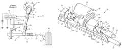
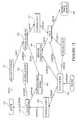
- Electric motor 38is actuated by a controller 52 that receives inputs from a torque sensor 54 and a rotational position sensor 56 .
- Sensor 56provides a steer angle signal to controller 52 .
- Universal joint 72secures a housing 75 to a mounting member 76 of rack assembly 30 .
- Universal joint 72contains two sets of hinge pins, or pivots 78 and 80 , the axis of each set being perpendicular to the other. Each set of pins is connected to the other by a central gimbal ring 82 .
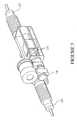
- Housing member 100is configured to have a mounting portion 101 which is configured to be received within opening 108 .
- Mounting portion 101is configured to be slidably received within opening 108 and contains the apertures into which bolts 104 are received.
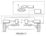
- Rack 45has a center position in which the steerable wheels of a vehicle are directed straight ahead relative to the vehicle.
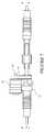
- rack-independent actuator 70will provide a return torque that assists in returning the steering system to a center position.
- the return torqueis generated by electric motor 38 , and a return torque component of the total desired torque signal is generated in controller 52 based upon the input received from sensors 122 , 124 , and 126 .
- an accurate signal of the steering positionis derived from absolute position sensor 124 .
Landscapes
- Engineering & Computer Science (AREA)
- Chemical & Material Sciences (AREA)
- Combustion & Propulsion (AREA)
- Transportation (AREA)
- Mechanical Engineering (AREA)
- Power Steering Mechanism (AREA)
Abstract
Description
Claims (26)
Priority Applications (6)
| Application Number | Priority Date | Filing Date | Title |
|---|---|---|---|
| US09/920,181US6488115B1 (en) | 2001-08-01 | 2001-08-01 | Apparatus and method for steering a vehicle |
| US10/262,730US6615947B2 (en) | 2001-08-01 | 2002-10-01 | Apparatus and method for steering a vehicle |
| US10/262,751US6705423B2 (en) | 2001-08-01 | 2002-10-01 | Apparatus and method for steering a vehicle |
| US10/765,731US20040154858A1 (en) | 2001-08-01 | 2004-01-26 | Apparatus and method for steering a vehicle |
| US11/016,039US7293626B2 (en) | 2001-08-01 | 2004-12-17 | Apparatus and method for steering a vehicle |
| US11/863,061US7591342B2 (en) | 2001-08-01 | 2007-09-27 | Apparatus and method for steering a vehicle |
Applications Claiming Priority (1)
| Application Number | Priority Date | Filing Date | Title |
|---|---|---|---|
| US09/920,181US6488115B1 (en) | 2001-08-01 | 2001-08-01 | Apparatus and method for steering a vehicle |
Related Child Applications (3)
| Application Number | Title | Priority Date | Filing Date |
|---|---|---|---|
| US10/262,751DivisionUS6705423B2 (en) | 2001-08-01 | 2002-10-01 | Apparatus and method for steering a vehicle |
| US10/262,730DivisionUS6615947B2 (en) | 2001-08-01 | 2002-10-01 | Apparatus and method for steering a vehicle |
| US11/863,061DivisionUS7591342B2 (en) | 2001-08-01 | 2007-09-27 | Apparatus and method for steering a vehicle |
Publications (1)
| Publication Number | Publication Date |
|---|---|
| US6488115B1true US6488115B1 (en) | 2002-12-03 |
Family
ID=25443301
Family Applications (4)
| Application Number | Title | Priority Date | Filing Date |
|---|---|---|---|
| US09/920,181Expired - LifetimeUS6488115B1 (en) | 2001-08-01 | 2001-08-01 | Apparatus and method for steering a vehicle |
| US10/262,730Expired - LifetimeUS6615947B2 (en) | 2001-08-01 | 2002-10-01 | Apparatus and method for steering a vehicle |
| US10/262,751Expired - LifetimeUS6705423B2 (en) | 2001-08-01 | 2002-10-01 | Apparatus and method for steering a vehicle |
| US10/765,731AbandonedUS20040154858A1 (en) | 2001-08-01 | 2004-01-26 | Apparatus and method for steering a vehicle |
Family Applications After (3)
| Application Number | Title | Priority Date | Filing Date |
|---|---|---|---|
| US10/262,730Expired - LifetimeUS6615947B2 (en) | 2001-08-01 | 2002-10-01 | Apparatus and method for steering a vehicle |
| US10/262,751Expired - LifetimeUS6705423B2 (en) | 2001-08-01 | 2002-10-01 | Apparatus and method for steering a vehicle |
| US10/765,731AbandonedUS20040154858A1 (en) | 2001-08-01 | 2004-01-26 | Apparatus and method for steering a vehicle |
Country Status (1)
| Country | Link |
|---|---|
| US (4) | US6488115B1 (en) |
Cited By (41)
| Publication number | Priority date | Publication date | Assignee | Title |
|---|---|---|---|---|
| US6546780B1 (en)* | 2001-12-10 | 2003-04-15 | Delphi Technologies, Inc. | Position sensor method and apparatus |
| WO2003059660A1 (en)* | 2002-01-10 | 2003-07-24 | Dayco Products, Llc | Belt driven mechanical boost power steering |
| US20030164060A1 (en)* | 2002-03-04 | 2003-09-04 | Ratko Menjak | Hand wheel actuator having stationary hub |
| US20030190413A1 (en)* | 2002-04-05 | 2003-10-09 | Van Steenkiste Thomas Hubert | Method of maintaining a non-obstructed interior opening in kinetic spray nozzles |
| US20030213641A1 (en)* | 2002-05-15 | 2003-11-20 | Koyo Seiko Co., Ltd. | Vehicle steering apparatus |
| US20040020707A1 (en)* | 2001-12-11 | 2004-02-05 | Visteon Global Technologies, Inc. | Method for installing flexibly coupled electric power assist steering system |
| US6691819B2 (en)* | 2001-09-17 | 2004-02-17 | Delphi Technologies, Inc. | Actuator for active front wheel steering system |
| US20040065432A1 (en)* | 2002-10-02 | 2004-04-08 | Smith John R. | High performance thermal stack for electrical components |
| US20040065391A1 (en)* | 2002-10-02 | 2004-04-08 | Smith John R | Direct application of catalysts to substrates via a thermal spray process for treatment of the atmosphere |
| US20040101620A1 (en)* | 2002-11-22 | 2004-05-27 | Elmoursi Alaa A. | Method for aluminum metalization of ceramics for power electronics applications |
| US6749040B1 (en)* | 1999-09-01 | 2004-06-15 | Delphi Technologies, Inc. | Electric power assisted rack and pinion system |
| US20040142198A1 (en)* | 2003-01-21 | 2004-07-22 | Thomas Hubert Van Steenkiste | Magnetostrictive/magnetic material for use in torque sensors |
| US20040157000A1 (en)* | 2003-02-07 | 2004-08-12 | Steenkiste Thomas Hubert Van | Method for producing electrical contacts using selective melting and a low pressure kinetic spray process |
| US20040187605A1 (en)* | 2003-03-28 | 2004-09-30 | Malakondaiah Naidu | Integrating fluxgate for magnetostrictive torque sensors |
| US20040187606A1 (en)* | 2003-03-28 | 2004-09-30 | Nehl Thomas Wolfgang | Torque sensing apparatus for picking up a magnetic flux |
| US20040250631A1 (en)* | 2003-06-10 | 2004-12-16 | Pattok Eric D. | Apparatus for sensing position and/or torque |
| US20050040260A1 (en)* | 2003-08-21 | 2005-02-24 | Zhibo Zhao | Coaxial low pressure injection method and a gas collimator for a kinetic spray nozzle |
| US20050074560A1 (en)* | 2003-10-02 | 2005-04-07 | Fuller Brian K. | Correcting defective kinetically sprayed surfaces |
| US20050098376A1 (en)* | 2001-08-01 | 2005-05-12 | Ozsoylu Suat A. | Apparatus and method for steering a vehicle |
| US20050100489A1 (en)* | 2003-10-30 | 2005-05-12 | Steenkiste Thomas H.V. | Method for securing ceramic structures and forming electrical connections on the same |
| US20050160834A1 (en)* | 2004-01-23 | 2005-07-28 | Nehl Thomas W. | Assembly for measuring movement of and a torque applied to a shaft |
| US20050161532A1 (en)* | 2004-01-23 | 2005-07-28 | Steenkiste Thomas H.V. | Modified high efficiency kinetic spray nozzle |
| US20050189162A1 (en)* | 2002-01-29 | 2005-09-01 | Koyo Seiko Co. Ltd. | Electric power steering apparatus |
| US6949300B2 (en) | 2001-08-15 | 2005-09-27 | Delphi Technologies, Inc. | Product and method of brazing using kinetic sprayed coatings |
| US7001671B2 (en) | 2001-10-09 | 2006-02-21 | Delphi Technologies, Inc. | Kinetic sprayed electrical contacts on conductive substrates |
| US20070000716A1 (en)* | 2005-06-30 | 2007-01-04 | Globe Motors, Inc. | Steering system torque sensor |
| EP1777139A1 (en)* | 2005-10-24 | 2007-04-25 | Mando Corporation | Electric power sterring apparatus for automobile |
| WO2006138209A3 (en)* | 2005-06-13 | 2007-10-11 | Bo Cheng | Electric power steering systems |
| US20070262656A1 (en)* | 2006-05-12 | 2007-11-15 | Fulks Gary C | Control module |
| US20080011537A1 (en)* | 2001-08-01 | 2008-01-17 | Delphi Technologies Inc. | Apparatus and method for steering a vehicle |
| US7476422B2 (en) | 2002-05-23 | 2009-01-13 | Delphi Technologies, Inc. | Copper circuit formed by kinetic spray |
| US20110132682A1 (en)* | 2009-12-03 | 2011-06-09 | Hyundai Motor Company | Steer by wire apparatus |
| US8752664B2 (en)* | 2009-11-06 | 2014-06-17 | Thyssenkrupp Presta Ag | Steer-by-wire steering system having an electromechanical steering lock |
| CN105151115A (en)* | 2015-08-18 | 2015-12-16 | 捷伸电子科技(上海)有限公司 | Electric power steering system |
| US10160472B2 (en) | 2015-10-20 | 2018-12-25 | Steering Solutions Ip Holding Corporation | Steering column with stationary hub |
| US10160473B2 (en) | 2016-09-13 | 2018-12-25 | Steering Solutions Ip Holding Corporation | Steering column decoupling system |
| US10589774B2 (en) | 2015-05-01 | 2020-03-17 | Steering Solutions Ip Holding Corporation | Counter rotation steering wheel |
| US10766518B2 (en) | 2015-06-25 | 2020-09-08 | Steering Solutions Ip Holding Corporation | Rotation control system for a steering wheel and method |
| US11072366B2 (en)* | 2016-10-31 | 2021-07-27 | Thyssenkrupp Presta Ag | Method for controlling a steer-by-wire steering system with a reduced feedback in automatic drive mode |
| US11465682B2 (en)* | 2019-01-23 | 2022-10-11 | Zf Automotive Germany Gmbh | Sensor unit, steering wheel subassembly, rack subassembly and steering system |
| US20230286582A1 (en)* | 2022-03-09 | 2023-09-14 | Steering Solutions Ip Holding Corporation | Ball nut and ballscrew absolute position sensor for vehicle steering system |
Families Citing this family (17)
| Publication number | Priority date | Publication date | Assignee | Title |
|---|---|---|---|---|
| EP1373052B1 (en)* | 2001-03-28 | 2010-11-24 | Continental Teves AG & Co. oHG | Drive device of a motor vehicle axle steering module and an electromechanical motor vehicle steering system |
| US6488115B1 (en)* | 2001-08-01 | 2002-12-03 | Delphi Technologies, Inc. | Apparatus and method for steering a vehicle |
| US6820713B2 (en)* | 2002-07-17 | 2004-11-23 | Delphi Technologies, Inc. | Hand wheel actuator with steering-feel enhancement |
| US20040136873A1 (en)* | 2003-01-09 | 2004-07-15 | Argonaut Technologies, Inc. | Modular reactor system |
| DE10310492A1 (en)* | 2003-03-11 | 2004-09-23 | Zf Lenksysteme Gmbh | Power steering |
| DE10316599A1 (en)* | 2003-04-11 | 2004-11-18 | Contitech Antriebssysteme Gmbh | Gear device for drives of motor vehicle steering systems |
| DE10329292A1 (en)* | 2003-06-30 | 2005-01-20 | Zf Lenksysteme Gmbh | Device for generating a torque |
| US20050076110A1 (en)* | 2003-07-11 | 2005-04-07 | Boban Mathew | Generic inbox system and method |
| US20060006108A1 (en)* | 2004-07-08 | 2006-01-12 | Arias Jeffrey L | Fuel cell cartridge and fuel delivery system |
| US20060031340A1 (en)* | 2004-07-12 | 2006-02-09 | Boban Mathew | Apparatus and method for advanced attachment filtering within an integrated messaging platform |
| DE102006016429A1 (en)* | 2006-04-07 | 2007-10-11 | Zf Lenksysteme Gmbh | Steering assist drive |
| KR101049629B1 (en)* | 2006-10-16 | 2011-07-14 | 우베 고산 기카이 가부시키가이샤 | Stem slide device |
| US20100280878A1 (en)* | 2009-04-30 | 2010-11-04 | Wilson Matthew J | System and method for managing, reconciling, balancing, and forecasting financial media in self-service devices |
| US12054202B2 (en) | 2018-01-18 | 2024-08-06 | Zf Active Safety And Electronics Us Llc | Apparatus for use in turning steerable vehicle wheels |
| KR102667922B1 (en)* | 2020-02-18 | 2024-05-22 | 현대모비스 주식회사 | Steering feel control apparatus |
| US11952056B2 (en)* | 2020-04-02 | 2024-04-09 | Steering Solutions Ip Holding Corporation | Electric powered recirculating ball assembly |
| DE102021203404B4 (en)* | 2021-04-07 | 2024-06-13 | Robert Bosch Gesellschaft mit beschränkter Haftung | Method for maneuvering a vehicle |
Citations (28)
| Publication number | Priority date | Publication date | Assignee | Title |
|---|---|---|---|---|
| US637204A (en) | 1897-08-27 | 1899-11-14 | Frederick H Heath | Ball-bearing. |
| US1234779A (en) | 1915-05-20 | 1917-07-31 | Karl J Ljungberg | Ball-bearing. |
| US1284827A (en) | 1916-10-27 | 1918-11-12 | Josef Vorraber | Ball-bearing. |
| US1321417A (en) | 1919-09-29 | 1919-11-11 | August Carlborg | Shaft and axle bearing. |
| US4223254A (en) | 1976-09-23 | 1980-09-16 | Cam Gears Limited | Power assisted gear systems |
| US4651840A (en) | 1985-02-26 | 1987-03-24 | Honda Giken Kogyo Kabushiki Kaisha | Motor-driven power steering system |
| US4664211A (en) | 1984-11-29 | 1987-05-12 | Fuji Jukogyo Kabushiki Kaisha | Electric power steering system |
| US4681182A (en) | 1985-04-11 | 1987-07-21 | Jidosha Kiki Co., Ltd. | Electric power steering apparatus |
| US4686433A (en) | 1984-11-02 | 1987-08-11 | Honda Giken Kogyo Kabushiki Kaisha | Motor-driven power booster |
| US4719396A (en) | 1985-05-27 | 1988-01-12 | Honda Giken Kogyo Kabushiki Kaisha | Electric motor drive circuit for electric power steering systems for vehicles |
| US4730686A (en) | 1986-04-08 | 1988-03-15 | Honda Giken Kogyo Kabushiki Kaisha | Motor-driven power steering system and method of controlling same |
| US4751978A (en) | 1987-03-16 | 1988-06-21 | Trw Inc. | Electric assist steering system with alternator power source |
| US4754829A (en) | 1986-04-11 | 1988-07-05 | Honda Giken Kogyo Kabushiki Kaisha | Motor-driven power steering system for vehicles |
| US4765426A (en) | 1986-03-31 | 1988-08-23 | Honda Giken Kogyo Kabushiki Kaisha | Motor driven power steering system |
| US4771845A (en) | 1986-04-22 | 1988-09-20 | Honda Giken Kogyo Kabushiki Kaisha | Motor-driven power steering system and method of controlling same |
| US4785901A (en) | 1986-07-17 | 1988-11-22 | Tokai Trw & Co. Ltd. | Rack and pinion steering gear with electric power assistance |
| US4819170A (en) | 1986-03-24 | 1989-04-04 | Honda Giken Kogyo Kabushiki Kaisha | Motor-driven power steering system for automotive vehicles |
| US4825972A (en) | 1986-02-25 | 1989-05-02 | Honda Giken Kogyo Kabushiki Kaisha | Steering system for vehicles |
| US4837692A (en) | 1987-03-24 | 1989-06-06 | Honda Giken Kogyo Kabushiki Kaisha | Electric power steering system for vehicles |
| US5247441A (en) | 1990-09-25 | 1993-09-21 | Honda Giken Kogyo Kabushiki Kaisha | Vehicle steering control system |
| US5251135A (en) | 1990-09-25 | 1993-10-05 | Honda Giken Kogyo Kabushiki Kaisha | Vehicle steering control system |
| US5347458A (en) | 1990-09-25 | 1994-09-13 | Honda Giken Kogyo Kabushiki Kaisha | Vehicle steering control system |
| US5732791A (en) | 1995-11-30 | 1998-03-31 | Trw Inc. | Steering apparatus |
| US5991675A (en) | 1993-06-02 | 1999-11-23 | Honda Giken Kogyo Kabushiki Kaisha | Vehicle control system based on estimation of the driving skill of a vehicle operator |
| US6006854A (en) | 1997-07-29 | 1999-12-28 | Koyo Seiko Co., Ltd | Electric power steering apparatus |
| US6041885A (en) | 1997-07-01 | 2000-03-28 | Honda Giken Kogyo Kabushiki Kaisha | Electric power steering apparatus |
| US6298941B1 (en) | 1999-01-29 | 2001-10-09 | Dana Corp | Electro-hydraulic power steering system |
| US6389924B1 (en)* | 2000-12-05 | 2002-05-21 | Delphi Technologies, Inc. | Steering column for motor vehicle |
Family Cites Families (28)
| Publication number | Priority date | Publication date | Assignee | Title |
|---|---|---|---|---|
| US423818A (en)* | 1890-03-18 | Brake-shoe | ||
| US283263A (en)* | 1883-08-14 | Boot and shoe | ||
| US423817A (en)* | 1890-03-18 | Sewing-machine | ||
| US337404A (en)* | 1886-03-09 | Circle-iron for wagons | ||
| US427807A (en)* | 1890-05-13 | Cyeus bussey | ||
| US2329767A (en)* | 1941-06-28 | 1943-09-21 | Keeler Brass Co | Handle, drawer pull, or the like |
| US2525208A (en)* | 1946-09-27 | 1950-10-10 | Clink Ray | Sectional tool cabinet |
| US2575661A (en)* | 1950-01-20 | 1951-11-20 | Anne E Kass | Medical therapy cart |
| US2697244A (en)* | 1953-08-03 | 1954-12-21 | Emil L Lincke | Push-pull type furniture handle |
| US2981549A (en)* | 1959-01-16 | 1961-04-25 | Hotton George Richardson | Mobile tool stand |
| US3997218A (en)* | 1975-03-14 | 1976-12-14 | Wolf Hugo M | Cabinet structure for dental treatment room |
| US4120549A (en)* | 1977-04-27 | 1978-10-17 | Harvey Lee Bureau | Sheet metal tool chest support with sliding work shelf |
| US4415054A (en)* | 1982-08-05 | 1983-11-15 | Trw Inc. | Steering gear |
| US4586762A (en)* | 1983-07-18 | 1986-05-06 | Syntex (U.S.A.) Inc. | Door and drawer front having a recessed grasping surface |
| GB8603084D0 (en)* | 1986-02-07 | 1986-03-12 | Trw Cam Gears Ltd | Road vehicle power assisted steering system |
| US4742882A (en)* | 1986-03-12 | 1988-05-10 | Honda Giken Kogyo Kabushiki Kaisha | Motor-driven power steering device |
| US4880248A (en)* | 1988-05-03 | 1989-11-14 | Mark Elmer | Manually propelled automotive painting tool cart |
| US5221132A (en)* | 1991-08-30 | 1993-06-22 | Max Combs | Tool storage system with magnetic swinging arms |
| US5489106A (en)* | 1994-03-16 | 1996-02-06 | Sony Corporation | Clean room cart |
| US5588659A (en)* | 1995-03-29 | 1996-12-31 | Triple B Trenching, Inc. | Tool cart |
| US5673983A (en)* | 1995-04-21 | 1997-10-07 | Metro Industries, Inc. | Cassette assembly and unit dose medication cart using the cassette assembly |
| US5720535A (en)* | 1996-08-30 | 1998-02-24 | Waterloo Industries, Inc. | Cabinet construction and locking system |
| US5913582A (en)* | 1996-10-08 | 1999-06-22 | Coonan; Gary M. | Computer workstation |
| US6264219B1 (en)* | 1999-08-06 | 2001-07-24 | Dave W. Smith | Utility cart |
| US6626445B2 (en)* | 1999-12-02 | 2003-09-30 | Alcon Universal Ltd. | Cart for surgical console |
| US6578938B2 (en)* | 2001-02-28 | 2003-06-17 | Robert A. Norman | Securable toolchest with visual-surround workbench |
| US6488115B1 (en)* | 2001-08-01 | 2002-12-03 | Delphi Technologies, Inc. | Apparatus and method for steering a vehicle |
| US6688615B2 (en)* | 2002-02-15 | 2004-02-10 | Shwu Ruu Chen | Tool box having drawers |
- 2001
- 2001-08-01USUS09/920,181patent/US6488115B1/ennot_activeExpired - Lifetime
- 2002
- 2002-10-01USUS10/262,730patent/US6615947B2/ennot_activeExpired - Lifetime
- 2002-10-01USUS10/262,751patent/US6705423B2/ennot_activeExpired - Lifetime
- 2004
- 2004-01-26USUS10/765,731patent/US20040154858A1/ennot_activeAbandoned
Patent Citations (28)
| Publication number | Priority date | Publication date | Assignee | Title |
|---|---|---|---|---|
| US637204A (en) | 1897-08-27 | 1899-11-14 | Frederick H Heath | Ball-bearing. |
| US1234779A (en) | 1915-05-20 | 1917-07-31 | Karl J Ljungberg | Ball-bearing. |
| US1284827A (en) | 1916-10-27 | 1918-11-12 | Josef Vorraber | Ball-bearing. |
| US1321417A (en) | 1919-09-29 | 1919-11-11 | August Carlborg | Shaft and axle bearing. |
| US4223254A (en) | 1976-09-23 | 1980-09-16 | Cam Gears Limited | Power assisted gear systems |
| US4686433A (en) | 1984-11-02 | 1987-08-11 | Honda Giken Kogyo Kabushiki Kaisha | Motor-driven power booster |
| US4664211A (en) | 1984-11-29 | 1987-05-12 | Fuji Jukogyo Kabushiki Kaisha | Electric power steering system |
| US4651840A (en) | 1985-02-26 | 1987-03-24 | Honda Giken Kogyo Kabushiki Kaisha | Motor-driven power steering system |
| US4681182A (en) | 1985-04-11 | 1987-07-21 | Jidosha Kiki Co., Ltd. | Electric power steering apparatus |
| US4719396A (en) | 1985-05-27 | 1988-01-12 | Honda Giken Kogyo Kabushiki Kaisha | Electric motor drive circuit for electric power steering systems for vehicles |
| US4825972A (en) | 1986-02-25 | 1989-05-02 | Honda Giken Kogyo Kabushiki Kaisha | Steering system for vehicles |
| US4819170A (en) | 1986-03-24 | 1989-04-04 | Honda Giken Kogyo Kabushiki Kaisha | Motor-driven power steering system for automotive vehicles |
| US4765426A (en) | 1986-03-31 | 1988-08-23 | Honda Giken Kogyo Kabushiki Kaisha | Motor driven power steering system |
| US4730686A (en) | 1986-04-08 | 1988-03-15 | Honda Giken Kogyo Kabushiki Kaisha | Motor-driven power steering system and method of controlling same |
| US4754829A (en) | 1986-04-11 | 1988-07-05 | Honda Giken Kogyo Kabushiki Kaisha | Motor-driven power steering system for vehicles |
| US4771845A (en) | 1986-04-22 | 1988-09-20 | Honda Giken Kogyo Kabushiki Kaisha | Motor-driven power steering system and method of controlling same |
| US4785901A (en) | 1986-07-17 | 1988-11-22 | Tokai Trw & Co. Ltd. | Rack and pinion steering gear with electric power assistance |
| US4751978A (en) | 1987-03-16 | 1988-06-21 | Trw Inc. | Electric assist steering system with alternator power source |
| US4837692A (en) | 1987-03-24 | 1989-06-06 | Honda Giken Kogyo Kabushiki Kaisha | Electric power steering system for vehicles |
| US5247441A (en) | 1990-09-25 | 1993-09-21 | Honda Giken Kogyo Kabushiki Kaisha | Vehicle steering control system |
| US5251135A (en) | 1990-09-25 | 1993-10-05 | Honda Giken Kogyo Kabushiki Kaisha | Vehicle steering control system |
| US5347458A (en) | 1990-09-25 | 1994-09-13 | Honda Giken Kogyo Kabushiki Kaisha | Vehicle steering control system |
| US5991675A (en) | 1993-06-02 | 1999-11-23 | Honda Giken Kogyo Kabushiki Kaisha | Vehicle control system based on estimation of the driving skill of a vehicle operator |
| US5732791A (en) | 1995-11-30 | 1998-03-31 | Trw Inc. | Steering apparatus |
| US6041885A (en) | 1997-07-01 | 2000-03-28 | Honda Giken Kogyo Kabushiki Kaisha | Electric power steering apparatus |
| US6006854A (en) | 1997-07-29 | 1999-12-28 | Koyo Seiko Co., Ltd | Electric power steering apparatus |
| US6298941B1 (en) | 1999-01-29 | 2001-10-09 | Dana Corp | Electro-hydraulic power steering system |
| US6389924B1 (en)* | 2000-12-05 | 2002-05-21 | Delphi Technologies, Inc. | Steering column for motor vehicle |
Cited By (73)
| Publication number | Priority date | Publication date | Assignee | Title |
|---|---|---|---|---|
| US6749040B1 (en)* | 1999-09-01 | 2004-06-15 | Delphi Technologies, Inc. | Electric power assisted rack and pinion system |
| US7293626B2 (en) | 2001-08-01 | 2007-11-13 | Delphi Technologies, Inc. | Apparatus and method for steering a vehicle |
| US7591342B2 (en) | 2001-08-01 | 2009-09-22 | Delphi Technologies, Inc. | Apparatus and method for steering a vehicle |
| US20050098376A1 (en)* | 2001-08-01 | 2005-05-12 | Ozsoylu Suat A. | Apparatus and method for steering a vehicle |
| US20080011537A1 (en)* | 2001-08-01 | 2008-01-17 | Delphi Technologies Inc. | Apparatus and method for steering a vehicle |
| US6949300B2 (en) | 2001-08-15 | 2005-09-27 | Delphi Technologies, Inc. | Product and method of brazing using kinetic sprayed coatings |
| US6691819B2 (en)* | 2001-09-17 | 2004-02-17 | Delphi Technologies, Inc. | Actuator for active front wheel steering system |
| US7001671B2 (en) | 2001-10-09 | 2006-02-21 | Delphi Technologies, Inc. | Kinetic sprayed electrical contacts on conductive substrates |
| US6546780B1 (en)* | 2001-12-10 | 2003-04-15 | Delphi Technologies, Inc. | Position sensor method and apparatus |
| US20040020707A1 (en)* | 2001-12-11 | 2004-02-05 | Visteon Global Technologies, Inc. | Method for installing flexibly coupled electric power assist steering system |
| US6953103B2 (en)* | 2001-12-11 | 2005-10-11 | Visteon Global Technologies, Inc. | Method for installing flexibly coupled electric power assist steering system |
| US6666294B2 (en)* | 2002-01-10 | 2003-12-23 | Dayco Products, Llc | Belt driven mechanical boost power steering |
| WO2003059660A1 (en)* | 2002-01-10 | 2003-07-24 | Dayco Products, Llc | Belt driven mechanical boost power steering |
| US7413052B2 (en) | 2002-01-29 | 2008-08-19 | Jtekt Corporation | Electric power steering apparatus |
| US7191866B2 (en)* | 2002-01-29 | 2007-03-20 | Koyo Seiko Co., Ltd. | Electric power steering apparatus |
| US20070187169A1 (en)* | 2002-01-29 | 2007-08-16 | Hiroto Sasaki | Electric power steering apparatus |
| US20070158130A1 (en)* | 2002-01-29 | 2007-07-12 | Takehiro Saruwatari | Electric power steering apparatus |
| US7237647B2 (en)* | 2002-01-29 | 2007-07-03 | Jtekt Corporation | Electric power steering apparatus |
| US7360624B2 (en) | 2002-01-29 | 2008-04-22 | Jtekt Corporation | Electric power steering apparatus |
| US20050197224A1 (en)* | 2002-01-29 | 2005-09-08 | Koyo Seiko Co., Ltd. | Electric power steering apparatus |
| US20050192143A1 (en)* | 2002-01-29 | 2005-09-01 | Koyo Seiko Co., Ltd. | Electric power steering apparatus |
| US20050189162A1 (en)* | 2002-01-29 | 2005-09-01 | Koyo Seiko Co. Ltd. | Electric power steering apparatus |
| US7490696B2 (en) | 2002-01-29 | 2009-02-17 | Jtekt Corporation | Electric power steering apparatus |
| US20030164060A1 (en)* | 2002-03-04 | 2003-09-04 | Ratko Menjak | Hand wheel actuator having stationary hub |
| US6892605B2 (en)* | 2002-03-04 | 2005-05-17 | Delphi Technologies, Inc. | Hand wheel actuator having stationary hub |
| US20030190413A1 (en)* | 2002-04-05 | 2003-10-09 | Van Steenkiste Thomas Hubert | Method of maintaining a non-obstructed interior opening in kinetic spray nozzles |
| US6896933B2 (en) | 2002-04-05 | 2005-05-24 | Delphi Technologies, Inc. | Method of maintaining a non-obstructed interior opening in kinetic spray nozzles |
| US20030213641A1 (en)* | 2002-05-15 | 2003-11-20 | Koyo Seiko Co., Ltd. | Vehicle steering apparatus |
| US6719088B2 (en)* | 2002-05-15 | 2004-04-13 | Koyo Seiko Co., Ltd. | Vehicle steering apparatus |
| US7476422B2 (en) | 2002-05-23 | 2009-01-13 | Delphi Technologies, Inc. | Copper circuit formed by kinetic spray |
| US6924249B2 (en) | 2002-10-02 | 2005-08-02 | Delphi Technologies, Inc. | Direct application of catalysts to substrates via a thermal spray process for treatment of the atmosphere |
| US20040065432A1 (en)* | 2002-10-02 | 2004-04-08 | Smith John R. | High performance thermal stack for electrical components |
| US20040065391A1 (en)* | 2002-10-02 | 2004-04-08 | Smith John R | Direct application of catalysts to substrates via a thermal spray process for treatment of the atmosphere |
| US20040101620A1 (en)* | 2002-11-22 | 2004-05-27 | Elmoursi Alaa A. | Method for aluminum metalization of ceramics for power electronics applications |
| US20040142198A1 (en)* | 2003-01-21 | 2004-07-22 | Thomas Hubert Van Steenkiste | Magnetostrictive/magnetic material for use in torque sensors |
| US20040157000A1 (en)* | 2003-02-07 | 2004-08-12 | Steenkiste Thomas Hubert Van | Method for producing electrical contacts using selective melting and a low pressure kinetic spray process |
| US6872427B2 (en) | 2003-02-07 | 2005-03-29 | Delphi Technologies, Inc. | Method for producing electrical contacts using selective melting and a low pressure kinetic spray process |
| US20040187606A1 (en)* | 2003-03-28 | 2004-09-30 | Nehl Thomas Wolfgang | Torque sensing apparatus for picking up a magnetic flux |
| US6871553B2 (en) | 2003-03-28 | 2005-03-29 | Delphi Technologies, Inc. | Integrating fluxgate for magnetostrictive torque sensors |
| US20050103126A1 (en)* | 2003-03-28 | 2005-05-19 | Delphi Technologies, Inc. | Integrating fluxgate for magnetostrictive torque sensors |
| US20040187605A1 (en)* | 2003-03-28 | 2004-09-30 | Malakondaiah Naidu | Integrating fluxgate for magnetostrictive torque sensors |
| US7188533B2 (en) | 2003-06-10 | 2007-03-13 | Delphi Technologies, Inc. | Apparatus for sensing position and/or torque |
| US20040250631A1 (en)* | 2003-06-10 | 2004-12-16 | Pattok Eric D. | Apparatus for sensing position and/or torque |
| US7021160B2 (en) | 2003-06-10 | 2006-04-04 | Delphi Technologies, Inc. | Apparatus for sensing position and/or torque |
| US20050172727A1 (en)* | 2003-06-10 | 2005-08-11 | Delphi Technologies, Inc. | Apparatus for sensing position and/or torque |
| US20050040260A1 (en)* | 2003-08-21 | 2005-02-24 | Zhibo Zhao | Coaxial low pressure injection method and a gas collimator for a kinetic spray nozzle |
| US20050074560A1 (en)* | 2003-10-02 | 2005-04-07 | Fuller Brian K. | Correcting defective kinetically sprayed surfaces |
| US7351450B2 (en) | 2003-10-02 | 2008-04-01 | Delphi Technologies, Inc. | Correcting defective kinetically sprayed surfaces |
| US20050100489A1 (en)* | 2003-10-30 | 2005-05-12 | Steenkiste Thomas H.V. | Method for securing ceramic structures and forming electrical connections on the same |
| US7335341B2 (en) | 2003-10-30 | 2008-02-26 | Delphi Technologies, Inc. | Method for securing ceramic structures and forming electrical connections on the same |
| US7475831B2 (en) | 2004-01-23 | 2009-01-13 | Delphi Technologies, Inc. | Modified high efficiency kinetic spray nozzle |
| US7024946B2 (en) | 2004-01-23 | 2006-04-11 | Delphi Technologies, Inc. | Assembly for measuring movement of and a torque applied to a shaft |
| US20050161532A1 (en)* | 2004-01-23 | 2005-07-28 | Steenkiste Thomas H.V. | Modified high efficiency kinetic spray nozzle |
| US20050160834A1 (en)* | 2004-01-23 | 2005-07-28 | Nehl Thomas W. | Assembly for measuring movement of and a torque applied to a shaft |
| WO2006138209A3 (en)* | 2005-06-13 | 2007-10-11 | Bo Cheng | Electric power steering systems |
| US7412906B2 (en) | 2005-06-30 | 2008-08-19 | Globe Motors, Inc. | Steering system torque sensor |
| US20070000716A1 (en)* | 2005-06-30 | 2007-01-04 | Globe Motors, Inc. | Steering system torque sensor |
| US20070089926A1 (en)* | 2005-10-24 | 2007-04-26 | Mando Corporation | Electric power steering apparatus for automobile |
| EP1777139A1 (en)* | 2005-10-24 | 2007-04-25 | Mando Corporation | Electric power sterring apparatus for automobile |
| US7485984B2 (en) | 2006-05-12 | 2009-02-03 | Delphi Technologies, Inc. | Control module |
| US20070262656A1 (en)* | 2006-05-12 | 2007-11-15 | Fulks Gary C | Control module |
| US8752664B2 (en)* | 2009-11-06 | 2014-06-17 | Thyssenkrupp Presta Ag | Steer-by-wire steering system having an electromechanical steering lock |
| US20110132682A1 (en)* | 2009-12-03 | 2011-06-09 | Hyundai Motor Company | Steer by wire apparatus |
| US8789647B2 (en)* | 2009-12-03 | 2014-07-29 | Hyundai Motor Company | Steer by wire apparatus |
| US10589774B2 (en) | 2015-05-01 | 2020-03-17 | Steering Solutions Ip Holding Corporation | Counter rotation steering wheel |
| US10766518B2 (en) | 2015-06-25 | 2020-09-08 | Steering Solutions Ip Holding Corporation | Rotation control system for a steering wheel and method |
| CN105151115A (en)* | 2015-08-18 | 2015-12-16 | 捷伸电子科技(上海)有限公司 | Electric power steering system |
| US10160472B2 (en) | 2015-10-20 | 2018-12-25 | Steering Solutions Ip Holding Corporation | Steering column with stationary hub |
| US10160473B2 (en) | 2016-09-13 | 2018-12-25 | Steering Solutions Ip Holding Corporation | Steering column decoupling system |
| US11072366B2 (en)* | 2016-10-31 | 2021-07-27 | Thyssenkrupp Presta Ag | Method for controlling a steer-by-wire steering system with a reduced feedback in automatic drive mode |
| US11465682B2 (en)* | 2019-01-23 | 2022-10-11 | Zf Automotive Germany Gmbh | Sensor unit, steering wheel subassembly, rack subassembly and steering system |
| US20230286582A1 (en)* | 2022-03-09 | 2023-09-14 | Steering Solutions Ip Holding Corporation | Ball nut and ballscrew absolute position sensor for vehicle steering system |
| US12330709B2 (en)* | 2022-03-09 | 2025-06-17 | Steering Solutions Ip Holding Corporation | Ball nut and ballscrew absolute position sensor for vehicle steering system |
Also Published As
| Publication number | Publication date |
|---|---|
| US20030029668A1 (en) | 2003-02-13 |
| US20040154858A1 (en) | 2004-08-12 |
| US20030024760A1 (en) | 2003-02-06 |
| US6615947B2 (en) | 2003-09-09 |
| US6705423B2 (en) | 2004-03-16 |
Similar Documents
| Publication | Publication Date | Title |
|---|---|---|
| US6488115B1 (en) | Apparatus and method for steering a vehicle | |
| US7591342B2 (en) | Apparatus and method for steering a vehicle | |
| EP1559630B1 (en) | Apparatus for steering a vehicle | |
| US7293626B2 (en) | Apparatus and method for steering a vehicle | |
| EP1270369B1 (en) | Ball-screw assembly isolator | |
| CN109153406B (en) | Steer-by-wire steering system and method for controlling the same | |
| US8678405B2 (en) | Motor vehicle steering system | |
| US20020189888A1 (en) | Steer-by wire handwheel actuator | |
| US20230052313A1 (en) | Electric steering assemblies for commercial vehicles | |
| US20240157999A1 (en) | Methods and systems for a steer-by-wire system with sensor devices | |
| JP3433324B2 (en) | Motor vehicle having at least one part controllable via at least one operating lever | |
| WO2003011674A1 (en) | Apparatus and method for steering a vehicle | |
| US11952056B2 (en) | Electric powered recirculating ball assembly | |
| US10807633B2 (en) | Electric power steering assembly and system with anti-rotation coupler | |
| JP5491930B2 (en) | Vehicle power steering device | |
| GB2383021A (en) | Steering system having an interlocking mechanism | |
| JP2952910B2 (en) | Electric power steering system | |
| EP1595766A2 (en) | Steering device for motor vehicles in general | |
| KR101316837B1 (en) | Steer-by-wire steering system | |
| US20230331286A1 (en) | Vehicle steering system having multi-stage reduction mechanism | |
| EP1944217B1 (en) | Center-takeoff rack-and-pinion steering apparatus | |
| JP2006159962A (en) | Steering device | |
| JP4093062B2 (en) | Electric power steering device | |
| JP2022014258A (en) | Steering apparatus | |
| JPS5820567A (en) | Steering gear for vehicle |
Legal Events
| Date | Code | Title | Description |
|---|---|---|---|
| AS | Assignment | Owner name:DELPHI TECHNOLOGIES, INC., MICHIGAN Free format text:ASSIGNMENT OF ASSIGNORS INTEREST;ASSIGNORS:OZSOYLU, SUAT ALI;FERIEND, WILLIAM F.;PYRETT, MICHAEL R.;REEL/FRAME:012056/0146;SIGNING DATES FROM 20010720 TO 20010725 | |
| STCF | Information on status: patent grant | Free format text:PATENTED CASE | |
| FPAY | Fee payment | Year of fee payment:4 | |
| AS | Assignment | Owner name:GM GLOBAL TECHNOLOGY OPERATIONS, INC., MICHIGAN Free format text:ASSIGNMENT OF ASSIGNORS INTEREST;ASSIGNOR:DELPHI TECHNOLOGIES, INC.;REEL/FRAME:023449/0065 Effective date:20091002 Owner name:GM GLOBAL TECHNOLOGY OPERATIONS, INC.,MICHIGAN Free format text:ASSIGNMENT OF ASSIGNORS INTEREST;ASSIGNOR:DELPHI TECHNOLOGIES, INC.;REEL/FRAME:023449/0065 Effective date:20091002 | |
| AS | Assignment | Owner name:GM GLOBAL TECHNOLOGY OPERATIONS, INC.,MICHIGAN Free format text:ASSIGNMENT OF ASSIGNORS INTEREST;ASSIGNOR:DELPHI TECHNOLOGIES, INC.;REEL/FRAME:023988/0754 Effective date:20091002 Owner name:UNITED STATES DEPARTMENT OF THE TREASURY,DISTRICT Free format text:SECURITY AGREEMENT;ASSIGNOR:GM GLOBAL TECHNOLOGY OPERATIONS, INC.;REEL/FRAME:023990/0349 Effective date:20090710 Owner name:UAW RETIREE MEDICAL BENEFITS TRUST,MICHIGAN Free format text:SECURITY AGREEMENT;ASSIGNOR:GM GLOBAL TECHNOLOGY OPERATIONS, INC.;REEL/FRAME:023990/0831 Effective date:20090710 Owner name:GM GLOBAL TECHNOLOGY OPERATIONS, INC., MICHIGAN Free format text:ASSIGNMENT OF ASSIGNORS INTEREST;ASSIGNOR:DELPHI TECHNOLOGIES, INC.;REEL/FRAME:023988/0754 Effective date:20091002 Owner name:UNITED STATES DEPARTMENT OF THE TREASURY, DISTRICT Free format text:SECURITY AGREEMENT;ASSIGNOR:GM GLOBAL TECHNOLOGY OPERATIONS, INC.;REEL/FRAME:023990/0349 Effective date:20090710 Owner name:UAW RETIREE MEDICAL BENEFITS TRUST, MICHIGAN Free format text:SECURITY AGREEMENT;ASSIGNOR:GM GLOBAL TECHNOLOGY OPERATIONS, INC.;REEL/FRAME:023990/0831 Effective date:20090710 | |
| FPAY | Fee payment | Year of fee payment:8 | |
| AS | Assignment | Owner name:GM GLOBAL TECHNOLOGY OPERATIONS, INC., MICHIGAN Free format text:RELEASE BY SECURED PARTY;ASSIGNOR:UAW RETIREE MEDICAL BENEFITS TRUST;REEL/FRAME:025386/0503 Effective date:20101026 Owner name:GM GLOBAL TECHNOLOGY OPERATIONS, INC., MICHIGAN Free format text:RELEASE BY SECURED PARTY;ASSIGNOR:UNITED STATES DEPARTMENT OF THE TREASURY;REEL/FRAME:025386/0591 Effective date:20100420 | |
| AS | Assignment | Owner name:PACIFIC CENTURY MOTORS, INC., CHINA Free format text:ASSIGNMENT OF ASSIGNORS INTEREST;ASSIGNOR:GM GLOBAL TECHNOLOGY OPERATIONS, INC.;REEL/FRAME:027842/0918 Effective date:20101130 Owner name:GM GLOBAL TECHNOLOGY OPERATIONS, INC., MICHIGAN Free format text:ASSIGNMENT OF ASSIGNORS INTEREST;ASSIGNOR:GM GLOBAL TECHNOLOGY OPERATIONS, INC.;REEL/FRAME:027842/0918 Effective date:20101130 | |
| AS | Assignment | Owner name:STEERING SOLUTIONS IP HOLDING CORPORATION, MICHIGA Free format text:ASSIGNMENT OF ASSIGNORS INTEREST;ASSIGNORS:PACIFIC CENTURY MOTORS, INC.;NEXTEER (BEIJING) TECHNOLOGY CO., LTD.;REEL/FRAME:027870/0666 Effective date:20120126 | |
| FPAY | Fee payment | Year of fee payment:12 |