US6487418B1 - Free channel selection method - Google Patents
Free channel selection methodDownload PDFInfo
- Publication number
- US6487418B1 US6487418B1US09/296,969US29696999AUS6487418B1US 6487418 B1US6487418 B1US 6487418B1US 29696999 AUS29696999 AUS 29696999AUS 6487418 B1US6487418 B1US 6487418B1
- Authority
- US
- United States
- Prior art keywords
- channel
- signal strength
- channels
- handset
- value
- Prior art date
- Legal status (The legal status is an assumption and is not a legal conclusion. Google has not performed a legal analysis and makes no representation as to the accuracy of the status listed.)
- Expired - Lifetime
Links
Images


Classifications
- H—ELECTRICITY
- H04—ELECTRIC COMMUNICATION TECHNIQUE
- H04W—WIRELESS COMMUNICATION NETWORKS
- H04W36/00—Hand-off or reselection arrangements
- H04W36/06—Reselecting a communication resource in the serving access point
- H—ELECTRICITY
- H04—ELECTRIC COMMUNICATION TECHNIQUE
- H04W—WIRELESS COMMUNICATION NETWORKS
- H04W36/00—Hand-off or reselection arrangements
- H04W36/24—Reselection being triggered by specific parameters
- H04W36/30—Reselection being triggered by specific parameters by measured or perceived connection quality data
- H04W36/302—Reselection being triggered by specific parameters by measured or perceived connection quality data due to low signal strength
- H—ELECTRICITY
- H04—ELECTRIC COMMUNICATION TECHNIQUE
- H04W—WIRELESS COMMUNICATION NETWORKS
- H04W24/00—Supervisory, monitoring or testing arrangements
- H—ELECTRICITY
- H04—ELECTRIC COMMUNICATION TECHNIQUE
- H04W—WIRELESS COMMUNICATION NETWORKS
- H04W76/00—Connection management
- H04W76/10—Connection setup
Definitions
- the present inventionrelates to an apparatus and method for cordless telephonic communication and, more particularly, for selecting a free channel for such communication.
- Cordless, or wireless, telephonestypically include a base station and a separate handset unit which is typically adapted to be seated in a cradle formed in the base station.
- the general operation of the wireless telephoneis controlled by a micro controller integrated therein.
- Such telephonesare commonly capable of operating, i.e., transmitting and receiving signals, on any one of a number of separate channels.
- a radio frequency (RF) moduleis typically utilized by the micro controller for establishing communication on a single channel, the selection of which channel is discussed below.
- RFradio frequency
- Time division multiplexingsuch as duplexing, may be utilized to both transmit and receive signals on the same channel. Transmit and receive time slots are allocated so signals are alternately transmitted and received, respectively, in the different time slots.
- the transmit and receive time slotsare of substantially equal duration and may be non-overlapping.
- the telephoneautomatically samples signals from each channel to determine which channel is free, i.e., has the least amount of signal traffic on it.
- the free channel selectionis performed according to a predefined algorithm.
- a predefined algorithmOne example may be that each of the channels is examined, or sampled, for radio frequency activity for a period of time from between 200 milliseconds (ms) to 2 seconds.
- the channel with the lowest radio frequency activityis the optimum channel to be used to establish a radio link between the handset unit and the base station.
- the signal samplesare valid for only a predetermined period of time. Therefore, all channels must be sampled and re-examined repeatedly.
- the free channel selection functionis performed typically by the micro controller according to software instructions stored therein. Accordingly, the micro controller sets the RF module to a particular channel. In one embodiment, the signal is then sampled at least four times during a 2 ms transmit/receive window. A Receive Signal Strength Indicator (RSSI) circuit then provides the strength of the signal samples. The micro controller reads the RSSI level for the signals of each channel and, using conventional comparison techniques, selects for radio communication the channel having the lowest RSSI level.
- RSSIReceive Signal Strength Indicator
- a disadvantage of the foregoing process and systemis that substantial overhead is added to the micro controller, which inhibits the micro controller from performing other system tasks.
- Another disadvantage of the foregoing processis that it also shortens the life of the battery in the handset unit.
- One solution to this drawbackis to use a faster, more powerful micro controller which can manage the additional overhead. But, such a micro controller increases the cost of the telephone and increases the power requirement to operate it. Since the handset of a cordless telephone draws its power from a battery, increased power demands drain the battery faster, thereby decreasing the operating time.
- a free channel selector of the present inventioncomprises an A/D converter which digitizes the RSSI signal from a radio frequency (RF) module for a selected and monitored channel.
- the A/D convertergenerates, for each of a plurality of channels, a first signal indicative of the strength of the signals transmitted on the respective channel, and an end of conversion (EOC) signal.
- the first signal and the EOC signalare then provided to a peak detector circuit which compares the strength of the first signal to the signal strength of a previously selected channel.
- a memory device having an array of cellsfor storing values representative of the signal strength of the channel having the least signal activity, where the stored values stored in a cell having an address indicative of the channel on which the first signal represented by the stored value is carried.
- the address of the selected stored valueis indicative of the free channel.
- An advantage achieved with the present inventionis that it enables the use of relatively inexpensive micro controllers that require relatively little power in cordless telephones, thereby extending battery life and the operating time of the telephone.
- Another advantage achieved with the present inventionis that it frees up the micro controller to perform other tasks while the free channel selection process is being performed.
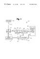
- FIG. 1is a schematic diagram of the free channel selector of the present invention
- FIG. 2is a flow chart illustrating control logic for operating a controller of the free channel selector of FIG. 1;
- FIG. 3is an embodiment of the peak detector circuit of the present invention.
- the selector 10forms a portion of a cordless telephone system, not shown in its entirety, but which is well known in the art. It is understood that the general operation of the telephone is controlled by a micro controller 12 in a manner well known to those skilled in the art.
- the selector 10includes a radio frequency (RF) module 14 electrically connected to the micro controller 12 via a micro controller bus 16 for receiving control signals for setting the RF module to a particular channel.
- An antenna 20configured for receiving radio signals on the numerous channels on which the telephone operates, preferably forty channels, communicates the received radio signals via a line 22 to an input of the RF module 14 .
- the RF module 14includes a bandpass filter (not shown) which passes that portion of the signal carried by the selected channel.
- the analog signal carried on the selected channelis then output from RF module 14 , via line 24 , to an analog-to-digital (A/D) converter circuit 36 . Suitable A/D converters are shown in the art.
- the peak detector 26is connected to the A/D converter 36 via two lines 30 and 32 for receiving, respectively, a 4-bit digitized signal in this example and an end of conversion (EOC) signal. During a time interval between the receipt of a start signal and a subsequent stop signal, the peak detector 26 samples the signal on the line 30 .
- EOCend of conversion
- Peak detector 26is preferably implemented as follows. Referring to FIG. 3, a 4-bit input from A/D converter 36 , on line 30 , which represents the digitized analog signal sampled from antenna 20 by RF module 14 is input to a pair of registers 62 and 64 . End of conversion signal (EOC) on line 32 from the A/D converter is used to latch in to register 62 the 4-bit signal at the end of each conversion of A/D converter 36 . Register 64 , meanwhile, holds the value of the signal having the highest value up to this point. The outputs of registers 62 and 64 are input to a comparator circuit 66 which compares the output of register 62 , the incoming signal sample, with the output of register 64 , the previously highest signal value.
- EOCEnd of conversion signal
- register 64If the incoming signal is higher than the previous signal held in register 64 , an enable signal from the comparator is ANDed with the EOC signal 32 from A/D converter 30 and the new signal value is input into register 64 as the new highest value signal.
- the output of register 64aside from being input to comparator 66 , is provided to a content addressable memory (CAM) 42 .
- CAMcontent addressable memory
- the CAM 42is connected to bus 40 for receiving the 4-bits of data from register 64 .
- the CAM 42includes numerous cells (not shown) for storing the data received on the bus 40 .
- the CAM 42is also connected to a bus 44 for receiving control signals and address data bits from the controller 12 , via channel latch 28 .
- the address from the controller 12corresponds to the channel number for the RF channel being sampled.
- the control signals received on the bus 44include enabling signals directing the CAM 42 to, respectively, write data to a cell via REG-CS signal 18 , search for a data cell address, and output data to the micro controller bus 16 via signal ⁇ overscore (WR) ⁇ 21 .
- the CAM 42can search the contents of the cells and return the address and contents of the cell having the lowest value stored therein, which address can be readily converted to a corresponding channel number. Because CAMs are well known to those skilled in the art the operation of the CAM 42 will not be described in further detail.
- the controller 12furthermore, includes a memory (not shown) for storing control logic instructions, a counter (not shown) for storing a six bit number representing the channel being sampled and an address in the CAM 42 , and a clock (not shown). Suitable controllers are known in the art.
- FIG. 2is a flow chart illustrating control logic for operating the free channel selector 10 in accordance with the present invention. It is understood that the logic may be implemented by instructions stored in the controller memory.
- step 200the controller 12 is powered up and, in step 202 , the counter is cleared to zero.
- step 206the controller 12 sets the RF module 14 to the channel indicated by the transmitted value of the counter. Hence, the RF module 14 will be initially set to channel 0.
- step 208the controller 12 transmits a start signal via the line 16 to the peak detector 26 , thereby causing the detector to start sampling the signal on the line 30 and to determine the maximum RSSI level of the signal thereon.
- step 210the clock is cleared to zero and, in step 212 , the clock is started.
- step 214the controller 12 reads the clock to determine whether 2 ms have elapsed. If a determination is made that 2 ms have not elapsed, then execution returns to step 214 ; otherwise, execution proceeds to step 218 .
- step 218a stop signal is transmitted via the line 16 to the peak detector 26 , thereby causing the peak detector to stop sampling and to output the maximum RSSI detected onto the line 40 .
- step 220the controller 12 transmits an enable signal to the AMD converter 36 to cause it to receive the signal on the line 24 , to convert it to a digital signal, and to then output the digital signal onto the line 30 .
- step 222the controller 12 transmits the contents of the counter to the CAM 42 .
- step 224the controller 12 transmits, via the bus 16 , a write signal to the channel latch 28 instructing the latch 28 to write the data represented by the digital signal on the bus 40 to the cell having an address specified by the value on the bus 44 , which is the value of the counter. It is understood that the cell address may also be specified by an offset to the value of the counter.
- step 226the controller 12 increments the counter by one.
- step 228a determination is made whether the counter is equal to the highest channel number, which preferably is 40. If it is determined that the counter is not equal to the highest channel number, then execution returns to step 206 . If it is determined that the counter is equal to 40, then execution proceeds to step 230 .
- step 230the controller 12 transmits a search signal to the CAM 42 directing it to search the cells of its memory and determine the address of the cell having the value representing the lowest RSSI level on a channel. It can be appreciated that the address of the cell having the lowest RSSI level represents the optimal channel on which the telephone should operate.
- step 232the controller 12 transmits a signal to the CAM 42 to output onto the bus 44 to the controller 12 , via channel latch 28 , the number of the optimal channel for communication. Execution then returns to step 202 .
- the present inventionhas several advantages. For example, relatively inexpensive micro controllers that require relatively little power may be used in cordless telephones, thereby extending battery life and the usefulness of the telephone. Further, the micro controller is freed up to perform other tasks while the free channel selection process is being performed. Moreover, the foregoing advantages are achieved without requiring any significant additional power to operate the telephone.
- the CAM 42may be configured to store as coupled pairs the channel numbers together with their respective signal strengths and to sort the pairs according to their signal strengths in either ascending or descending order. The optimal channel would then be that channel in either the highest or lowest memory cell.
Landscapes
- Engineering & Computer Science (AREA)
- Computer Networks & Wireless Communication (AREA)
- Signal Processing (AREA)
- Mobile Radio Communication Systems (AREA)
Abstract
Description
Claims (20)
Priority Applications (1)
| Application Number | Priority Date | Filing Date | Title |
|---|---|---|---|
| US09/296,969US6487418B1 (en) | 1997-05-22 | 1999-04-22 | Free channel selection method |
Applications Claiming Priority (2)
| Application Number | Priority Date | Filing Date | Title |
|---|---|---|---|
| US08/861,963US6021314A (en) | 1997-05-22 | 1997-05-22 | Free channel selector for selecting an optimal channel |
| US09/296,969US6487418B1 (en) | 1997-05-22 | 1999-04-22 | Free channel selection method |
Related Parent Applications (1)
| Application Number | Title | Priority Date | Filing Date |
|---|---|---|---|
| US08/861,963ContinuationUS6021314A (en) | 1997-05-22 | 1997-05-22 | Free channel selector for selecting an optimal channel |
Related Child Applications (1)
| Application Number | Title | Priority Date | Filing Date |
|---|---|---|---|
| US09/750,061ContinuationUS6380085B2 (en) | 1998-03-30 | 2000-12-29 | Method of manufacturing semiconductor devices |
Publications (1)
| Publication Number | Publication Date |
|---|---|
| US6487418B1true US6487418B1 (en) | 2002-11-26 |
Family
ID=25337235
Family Applications (2)
| Application Number | Title | Priority Date | Filing Date |
|---|---|---|---|
| US08/861,963Expired - LifetimeUS6021314A (en) | 1997-05-22 | 1997-05-22 | Free channel selector for selecting an optimal channel |
| US09/296,969Expired - LifetimeUS6487418B1 (en) | 1997-05-22 | 1999-04-22 | Free channel selection method |
Family Applications Before (1)
| Application Number | Title | Priority Date | Filing Date |
|---|---|---|---|
| US08/861,963Expired - LifetimeUS6021314A (en) | 1997-05-22 | 1997-05-22 | Free channel selector for selecting an optimal channel |
Country Status (1)
| Country | Link |
|---|---|
| US (2) | US6021314A (en) |
Cited By (9)
| Publication number | Priority date | Publication date | Assignee | Title |
|---|---|---|---|---|
| US20030013480A1 (en)* | 2001-07-11 | 2003-01-16 | Nec Corporation | Mobile station and frequency band detection method |
| US20040156382A1 (en)* | 2003-02-10 | 2004-08-12 | Jung-In Jang | Access point device and method for setting channel of the same |
| US6920117B1 (en)* | 1999-10-29 | 2005-07-19 | Oki Electric Industry Co., Ltd. | Communication channel selecting circuit corresponding to radio signal intensity |
| US20060177049A1 (en)* | 2005-01-26 | 2006-08-10 | Tsutomu Ukon | Cordless telephone set and additional device of the same |
| US20060183473A1 (en)* | 2005-01-28 | 2006-08-17 | Brother Kogyo Kabushiki Kaisha | Cordless apparatus |
| US7197315B1 (en)* | 2003-08-08 | 2007-03-27 | Intel Corporation | Method and apparatus to select a channel using performance metrics |
| EP1868296A1 (en)* | 2006-06-15 | 2007-12-19 | Semiconductor Ideas to The Market (ItoM) BV | Radio broadcast transceiver |
| US20080080418A1 (en)* | 2006-09-29 | 2008-04-03 | Ahmadreza Rofougaran | Method and system for antenna architecture for wcdma/hsdpa/hsudpa diversity and enhanced gsm/gprs/edge performance |
| US7436879B1 (en)* | 1999-01-07 | 2008-10-14 | Fujitsu Limited | Spread communication system and mobile station thereof |
Families Citing this family (6)
| Publication number | Priority date | Publication date | Assignee | Title |
|---|---|---|---|---|
| US6021314A (en)* | 1997-05-22 | 2000-02-01 | Advanced Micro Devices, Inc. | Free channel selector for selecting an optimal channel |
| US6169761B1 (en)* | 1998-04-01 | 2001-01-02 | Wavespan Corporation | Method and transceiver using an improved protocol for a frequency hop communication system |
| EP1045599A4 (en)* | 1998-10-26 | 2004-03-31 | Mitsubishi Electric Corp | COMMUNICATION LINE SELECTION AND MOBILE COMMUNICATION DEVICE |
| US6201953B1 (en)* | 1998-12-07 | 2001-03-13 | Trw Inc. | Method and apparatus for on-board testing of a communication satellite |
| US7359448B2 (en)* | 2002-08-21 | 2008-04-15 | Lear Corporation | Remote transmitter system and method |
| US12137383B2 (en)* | 2018-10-16 | 2024-11-05 | British Telecommunications Public Limited Company | Measuring channel performance in wireless local area networks |
Citations (10)
| Publication number | Priority date | Publication date | Assignee | Title |
|---|---|---|---|---|
| US4894856A (en)* | 1986-08-19 | 1990-01-16 | Fujitsu Limited | Cordless telephone set operated under multi-channel access |
| US5329591A (en)* | 1993-04-23 | 1994-07-12 | Magrill Barry J | Transmitter identification and validation system and method |
| US5329575A (en)* | 1990-04-26 | 1994-07-12 | Fujitsu Limited | Idle channel retrieving method and cordless communications system using the same |
| US5351271A (en)* | 1991-12-19 | 1994-09-27 | Institut Francais Du Petrole | Method and device for measuring the successive amplitude levels of signals received on a transmission channel |
| US5418839A (en)* | 1990-04-13 | 1995-05-23 | Phonemate, Inc. | Environmental adaptive mechanism for channel utilization in cordless telephones |
| US5655002A (en) | 1992-07-15 | 1997-08-05 | Orbitel Mobile Communications Limited | Radio telephone system with signal strength assessment |
| US5708968A (en)* | 1994-06-22 | 1998-01-13 | Nippon Mobile Communications | Channel segregation method |
| US5745853A (en) | 1994-06-27 | 1998-04-28 | Nokia Telecommunication Oy | Method for allocating radio channels in a quasi-transmission-trunked mobile communication system |
| US5809427A (en) | 1996-03-28 | 1998-09-15 | Motorola Inc. | Apparatus and method for channel acquisition in a communication system |
| US6021314A (en)* | 1997-05-22 | 2000-02-01 | Advanced Micro Devices, Inc. | Free channel selector for selecting an optimal channel |
- 1997
- 1997-05-22USUS08/861,963patent/US6021314A/ennot_activeExpired - Lifetime
- 1999
- 1999-04-22USUS09/296,969patent/US6487418B1/ennot_activeExpired - Lifetime
Patent Citations (10)
| Publication number | Priority date | Publication date | Assignee | Title |
|---|---|---|---|---|
| US4894856A (en)* | 1986-08-19 | 1990-01-16 | Fujitsu Limited | Cordless telephone set operated under multi-channel access |
| US5418839A (en)* | 1990-04-13 | 1995-05-23 | Phonemate, Inc. | Environmental adaptive mechanism for channel utilization in cordless telephones |
| US5329575A (en)* | 1990-04-26 | 1994-07-12 | Fujitsu Limited | Idle channel retrieving method and cordless communications system using the same |
| US5351271A (en)* | 1991-12-19 | 1994-09-27 | Institut Francais Du Petrole | Method and device for measuring the successive amplitude levels of signals received on a transmission channel |
| US5655002A (en) | 1992-07-15 | 1997-08-05 | Orbitel Mobile Communications Limited | Radio telephone system with signal strength assessment |
| US5329591A (en)* | 1993-04-23 | 1994-07-12 | Magrill Barry J | Transmitter identification and validation system and method |
| US5708968A (en)* | 1994-06-22 | 1998-01-13 | Nippon Mobile Communications | Channel segregation method |
| US5745853A (en) | 1994-06-27 | 1998-04-28 | Nokia Telecommunication Oy | Method for allocating radio channels in a quasi-transmission-trunked mobile communication system |
| US5809427A (en) | 1996-03-28 | 1998-09-15 | Motorola Inc. | Apparatus and method for channel acquisition in a communication system |
| US6021314A (en)* | 1997-05-22 | 2000-02-01 | Advanced Micro Devices, Inc. | Free channel selector for selecting an optimal channel |
Cited By (16)
| Publication number | Priority date | Publication date | Assignee | Title |
|---|---|---|---|---|
| US7436879B1 (en)* | 1999-01-07 | 2008-10-14 | Fujitsu Limited | Spread communication system and mobile station thereof |
| US6920117B1 (en)* | 1999-10-29 | 2005-07-19 | Oki Electric Industry Co., Ltd. | Communication channel selecting circuit corresponding to radio signal intensity |
| GB2380360A (en)* | 2001-07-11 | 2003-04-02 | Nec Corp | Mobile station which detects a prioritised or previously-used frequency band to use |
| US20030013480A1 (en)* | 2001-07-11 | 2003-01-16 | Nec Corporation | Mobile station and frequency band detection method |
| GB2380360B (en)* | 2001-07-11 | 2006-04-12 | Nec Corp | Mobile station and frequency-band detection method |
| US7453848B2 (en)* | 2003-02-10 | 2008-11-18 | Samsung Electronics Co., Ltd. | Access point device and method for setting channel of the same |
| US20040156382A1 (en)* | 2003-02-10 | 2004-08-12 | Jung-In Jang | Access point device and method for setting channel of the same |
| US7197315B1 (en)* | 2003-08-08 | 2007-03-27 | Intel Corporation | Method and apparatus to select a channel using performance metrics |
| US20060177049A1 (en)* | 2005-01-26 | 2006-08-10 | Tsutomu Ukon | Cordless telephone set and additional device of the same |
| US20060183473A1 (en)* | 2005-01-28 | 2006-08-17 | Brother Kogyo Kabushiki Kaisha | Cordless apparatus |
| EP1868296A1 (en)* | 2006-06-15 | 2007-12-19 | Semiconductor Ideas to The Market (ItoM) BV | Radio broadcast transceiver |
| WO2007144101A3 (en)* | 2006-06-15 | 2008-01-24 | Semiconductor Ideas Market Bv | Rf radio broadcast transceiver |
| US20090170446A1 (en)* | 2006-06-15 | 2009-07-02 | Heijnen Antonius L J C | Rf radio broadcast transceiver |
| US20090270047A1 (en)* | 2006-06-15 | 2009-10-29 | Heijnen Antonius L J C | Tuning identifying broadcast transceiver |
| US20080080418A1 (en)* | 2006-09-29 | 2008-04-03 | Ahmadreza Rofougaran | Method and system for antenna architecture for wcdma/hsdpa/hsudpa diversity and enhanced gsm/gprs/edge performance |
| US8396044B2 (en)* | 2006-09-29 | 2013-03-12 | Broadcom Corporation | Method and system for antenna architecture for WCDMA/HSDPA/HSUDPA diversity and enhanced GSM/GPRS/edge performance |
Also Published As
| Publication number | Publication date |
|---|---|
| US6021314A (en) | 2000-02-01 |
Similar Documents
| Publication | Publication Date | Title |
|---|---|---|
| US6487418B1 (en) | Free channel selection method | |
| US5097484A (en) | Diversity transmission and reception method and equipment | |
| JP3575803B2 (en) | Selective diversity system | |
| US5867292A (en) | Method and apparatus for cordless infrared communication | |
| US4328581A (en) | Adaptive HF communication system | |
| JP2959499B2 (en) | Wireless communication device | |
| US5210752A (en) | Radio tele-communication system using multichannel access scheme | |
| JP3303816B2 (en) | Diversity receiver | |
| US4720710A (en) | Paging receiver having a plurality of test modes | |
| EP1294207B1 (en) | A method for performing measurements in a wireless terminal and a wireless terminal | |
| US6469990B1 (en) | Method and apparatus for controlling the reception of data packets in a mobile station | |
| US5706317A (en) | Synchronization device for a terminal of a radio communication system | |
| KR100438745B1 (en) | Protocol for exchanging signaling signals in a cordless telephone | |
| JP3042755B2 (en) | Mobile station zone transfer control method | |
| JP2732365B2 (en) | Transmission power control method | |
| JP2974880B2 (en) | Time diversity receiver | |
| JP2516998B2 (en) | Wireless communication equipment | |
| JP3344560B2 (en) | Wireless communication device | |
| JPS60137143A (en) | Setting system for talking channel | |
| JP2567755B2 (en) | Wireless phone call channel setting method | |
| KR960003103B1 (en) | Probability Distributed Channel Occupancy Method in MCA Method | |
| EP0505204A2 (en) | Radiotelephone set | |
| JPH0453078Y2 (en) | ||
| KR0121965B1 (en) | Method for accessing the time slot of the portable terminal | |
| KR970006911B1 (en) | Control method of premises wireless telephone system |
Legal Events
| Date | Code | Title | Description |
|---|---|---|---|
| AS | Assignment | Owner name:MORGAN STANLEY & CO. INCORPORATED, NEW YORK Free format text:SECURITY INTEREST;ASSIGNOR:LEGERITY, INC.;REEL/FRAME:011601/0539 Effective date:20000804 | |
| AS | Assignment | Owner name:LEGERITY, INC., TEXAS Free format text:ASSIGNMENT OF ASSIGNORS INTEREST;ASSIGNOR:ADVANCED MICRO DEVICES, INC.;REEL/FRAME:011700/0686 Effective date:20000731 | |
| AS | Assignment | Owner name:MORGAN STANLEY & CO. INCORPORATED, AS FACILITY COL Free format text:SECURITY AGREEMENT;ASSIGNORS:LEGERITY, INC.;LEGERITY HOLDINGS, INC.;LEGERITY INTERNATIONAL, INC.;REEL/FRAME:013372/0063 Effective date:20020930 | |
| STCF | Information on status: patent grant | Free format text:PATENTED CASE | |
| CC | Certificate of correction | ||
| FPAY | Fee payment | Year of fee payment:4 | |
| AS | Assignment | Owner name:SAXON IP ASSETS LLC, TEXAS Free format text:ASSIGNMENT OF ASSIGNORS INTEREST;ASSIGNOR:LEGERITY, INC.;REEL/FRAME:019246/0747 Effective date:20070504 | |
| AS | Assignment | Owner name:LEGERITY, INC., TEXAS Free format text:RELEASE OF SECURITY INTEREST;ASSIGNOR:MORGAN STANLEY SENIOR FUNDING INC., AS ADMINISTRATIVE AGENT, SUCCESSOR TO MORGAN STANLEY & CO. INCORPORATED;REEL/FRAME:019690/0647 Effective date:20070727 Owner name:LEGERITY, INC., TEXAS Free format text:RELEASE OF SECURITY INTEREST;ASSIGNOR:MORGAN STANLEY SENIOR FUNDING INC., AS ADMINISTRATIVE AGENT, SUCCESSOR TO MORGAN STANLEY & CO. INCORPORATED, AS FACILITY COLLATERAL AGENT;REEL/FRAME:019699/0854 Effective date:20070727 Owner name:LEGERITY HOLDINGS, INC., TEXAS Free format text:RELEASE OF SECURITY INTEREST;ASSIGNOR:MORGAN STANLEY SENIOR FUNDING INC., AS ADMINISTRATIVE AGENT, SUCCESSOR TO MORGAN STANLEY & CO. INCORPORATED, AS FACILITY COLLATERAL AGENT;REEL/FRAME:019699/0854 Effective date:20070727 Owner name:LEGERITY INTERNATIONAL, INC., TEXAS Free format text:RELEASE OF SECURITY INTEREST;ASSIGNOR:MORGAN STANLEY SENIOR FUNDING INC., AS ADMINISTRATIVE AGENT, SUCCESSOR TO MORGAN STANLEY & CO. INCORPORATED, AS FACILITY COLLATERAL AGENT;REEL/FRAME:019699/0854 Effective date:20070727 | |
| AS | Assignment | Owner name:SAXON INNOVATIONS, LLC, TEXAS Free format text:ASSIGNMENT OF ASSIGNORS INTEREST;ASSIGNOR:SAXON IP ASSETS, LLC;REEL/FRAME:020072/0445 Effective date:20071016 | |
| AS | Assignment | Owner name:RPX CORPORATION,CALIFORNIA Free format text:ASSIGNMENT OF ASSIGNORS INTEREST;ASSIGNOR:SAXON INNOVATIONS, LLC;REEL/FRAME:024202/0302 Effective date:20100324 | |
| AS | Assignment | Owner name:SAMSUNG ELECTRONICS CO., LTD.,KOREA, DEMOCRATIC PE Free format text:ASSIGNMENT OF ASSIGNORS INTEREST;ASSIGNOR:RPX CORPORATION;REEL/FRAME:024263/0633 Effective date:20100420 | |
| FPAY | Fee payment | Year of fee payment:8 | |
| FEPP | Fee payment procedure | Free format text:PAYOR NUMBER ASSIGNED (ORIGINAL EVENT CODE: ASPN); ENTITY STATUS OF PATENT OWNER: LARGE ENTITY | |
| FPAY | Fee payment | Year of fee payment:12 |