US6487022B1 - Transmitter using uniform intensity transmission for a wireless optical communication system - Google Patents
Transmitter using uniform intensity transmission for a wireless optical communication systemDownload PDFInfo
- Publication number
- US6487022B1 US6487022B1US09/938,896US93889601AUS6487022B1US 6487022 B1US6487022 B1US 6487022B1US 93889601 AUS93889601 AUS 93889601AUS 6487022 B1US6487022 B1US 6487022B1
- Authority
- US
- United States
- Prior art keywords
- optical element
- optical
- uniform intensity
- flat
- light source
- Prior art date
- Legal status (The legal status is an assumption and is not a legal conclusion. Google has not performed a legal analysis and makes no representation as to the accuracy of the status listed.)
- Expired - Lifetime
Links
Images


Classifications
- G—PHYSICS
- G02—OPTICS
- G02B—OPTICAL ELEMENTS, SYSTEMS OR APPARATUS
- G02B27/00—Optical systems or apparatus not provided for by any of the groups G02B1/00 - G02B26/00, G02B30/00
- G02B27/09—Beam shaping, e.g. changing the cross-sectional area, not otherwise provided for
- G02B27/0927—Systems for changing the beam intensity distribution, e.g. Gaussian to top-hat
- G—PHYSICS
- G02—OPTICS
- G02B—OPTICAL ELEMENTS, SYSTEMS OR APPARATUS
- G02B27/00—Optical systems or apparatus not provided for by any of the groups G02B1/00 - G02B26/00, G02B30/00
- G02B27/09—Beam shaping, e.g. changing the cross-sectional area, not otherwise provided for
- G—PHYSICS
- G02—OPTICS
- G02B—OPTICAL ELEMENTS, SYSTEMS OR APPARATUS
- G02B27/00—Optical systems or apparatus not provided for by any of the groups G02B1/00 - G02B26/00, G02B30/00
- G02B27/09—Beam shaping, e.g. changing the cross-sectional area, not otherwise provided for
- G02B27/0938—Using specific optical elements
- G02B27/0944—Diffractive optical elements, e.g. gratings, holograms
- H—ELECTRICITY
- H04—ELECTRIC COMMUNICATION TECHNIQUE
- H04B—TRANSMISSION
- H04B10/00—Transmission systems employing electromagnetic waves other than radio-waves, e.g. infrared, visible or ultraviolet light, or employing corpuscular radiation, e.g. quantum communication
Definitions
- This disclosurerelates generally to optical signals, and in particular but not exclusively, relates to optical signals for free space optical communication systems.
- the problem with the non-uniform intensity of the Gaussian beamis that it can cause signal loss to receivers not placed within the peak area of the beam. Stated in another way, receivers that receive the portion of the optical signals having the lower intensity along the fringes of the Gaussian distribution are more likely to experience signal loss or errors, as compared to receivers that receive the portion of the optical signal near the center or highest intensity of the Gaussian distribution.
- One aspect of the inventionincludes creating a uniform intensity flat-top beam from a non-uniform intensity optical beam, and canceling a divergence and correcting a phase of the uniform intensity flat-top beam that is created.
- FIG. 1Ais a block diagram illustrating a uniform intensity flat-top beam generator according to one embodiment of the present invention.
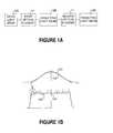
- FIG. 1Billustrates a difference in intensity between a Gaussian beam and a flat-top beam.
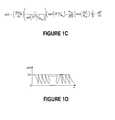
- FIG. 1Cis a phase modulo function formula in one dimension used to generate the uniform intensity flat-top beams according to one embodiment of the present invention.
- FIG. 1Dis a graph of the phase modulo function formula of FIG. 1 C.
- FIG. 2illustrates a schematic diagram of a Transformer Optical Module (TOM) according to one embodiment of the present invention.
- TOMTransformer Optical Module
- FIG. 3is a block diagram illustrating a point-to-sector transmitter according to one embodiment of the present invention.
- FIG. 4Ais a block diagram illustrating a multi-array transmitter (MAT) of flat-top intensity beam elements according to another embodiment of the present invention.
- MATmulti-array transmitter
- FIG. 4Billustrates a schematic diagram of a transmitter of individual flat-top intensity beam elements to specific locations according to another embodiment of the present invention.
- FIG. 5illustrates a schematic diagram of a uniform intensity flat-top beam generator according to one embodiment of the present invention.
- Embodiments of a system and method that use uniform intensity optical signals in free space optical communication systemsare described herein.
- numerous specific detailsare set forth to provide a thorough understanding of embodiments of the invention.
- One skilled in the relevant artwill recognize, however, that the invention can be practiced without one or more of the specific details, or with other methods, components, materials, etc.
- well-known structures, materials, or operationsare not shown or described in detail to avoid obscuring aspects of the invention.
- an embodiment of the inventionincludes a device that controls and reshapes optical signals generated by a laser or sent through fiber optic cables for eventual broadcast to various sectors.
- the optical traintransforms the input Gaussian beam into a flat-top beam, a beam with a uniform intensity distribution.
- the devicecan operate either in a super broadband sector spectral output mode, which is a combination of independent orders of diffraction, or be extended to operate as a multi-beam system, where spatially separated beams are obtained at the output of the transmitter.
- both the point-to-sector and multi-beam schemesare obtainable from a single source.
- FIG. 1Ais a block diagram illustrating a uniform flat-top beam generator according to one embodiment of the present invention.
- the uniform flat-top beam generatorcomprises a first optical element 10 and a second optical element 11 .
- the difference in intensity between a Gaussian beam 101 and a uniform intensity flat-top beam 102is illustrated in FIG. 1 B.
- the Gaussian beam 101has a peak that slopes down on both sides 103 whereas the flat-top beam has a uniform distribution across the entire width of the beam 104 , with some possible fluctuations as shown.
- the first optical element 10is placed in the path of a Gaussian optical beam 101 (FIG. 1B) to be transformed into a uniform intensity flat-top beam 102 (FIG. 1 B).
- the second optical element 11is placed in the path of the optical beam after it passes through the first optical element 10 .
- the first optical element 10 and the second optical element 11comprise diffractive optical elements (DOEs), such as diffractive glass lenses, or holographic glass lenses.
- DOEsdiffractive optical elements
- the lensescan be etched using a particular phase function formula.
- the phase functioncan be given by a formula seen in FIG. 1C in one embodiment.
- the phase modulo ⁇ (x) from the formula (FIG. 1C)is depicted in one dimension in FIG. 1 D.
- both lensescan be created so that the pattern scratched into the glass matches this particular phase function.
- Surfaces of the optical elements 10 , 11are determined by this surface profile of the phase modulo.
- the thickness of the lens 10 , 11 (FIG. 1A)can be given, in one embodiment, by the formula:
- the first optical element 10can be a lens etched to conform to the desired phase modulo formula.
- the second optical element 11can also be a lens etched to the same specification.
- the first optical element 10is placed in the path of an optical beam 12 a , with the etched side facing the optical beam 12 a .
- the beampasses through the first optical element 10 , the beam is transformed into a uniform flat-top beam 12 b .
- the resulting flat-top beam 12 bhas diverged and is out of phase with the original optical beam 12 a .
- the second optical element 11is placed after the first optical element 10 , except that it is placed backward—with the etched side facing the opposite direction and upside down with respect to the first optical element 10 .
- the flat-top beam 12 bpasses through the second optical element 11 , the divergence is canceled and the phase is corrected to match the original optical beam 12 a.
- FIG. 2is illustrates a schematic diagram of one embodiment of the present invention: a point-to-sector transmitter in a Transformer Optical Module (TOM).
- the TOMcomprises a housing 20 that encases the optical signal 12 a , the first optical element 10 , the second optical element 11 , a third optical element 13 and a collimating lens 14 .
- the optical signal 12 aenters the TOM housing 20 from a fiber interface 15 . After entering the TOM housing 20 , the optical signal 12 a passes through the first optical element 10 . After passing through the first optical element 10 , the optical signal 12 b then passes through the second optical element 11 . After passing through the second optical element 11 the optical signal 12 c continues and passes through the third optical element 13 , such as, for example, lenses, Dammann gratings, diffractive optic elements, or other optical components. An optical signal 12 d , after passing through the third optical element 13 , passes through the collimating lens 14 and is then transmitted as a collimated uniform intensity flat-top signal 12 e.
- the third optical element 13such as, for example, lenses, Dammann gratings, diffractive optic elements, or other optical components.
- An optical signal 12 dafter passing through the third optical element 13 , passes through the collimating lens 14 and is then transmitted as a collimated uniform intensity flat-top signal 12 e.
- the Gaussian beam 12 ais inputted by the fiber interface 15 .
- the TOMconverts the Gaussian beam from the fiber interface 15 into a collimated flat top with uniform intensity 12 e .
- the first and second optical elements 10 , 11perform the same function as described above.
- the first optical element 10transforms the Gaussian beam 12 a into a uniform intensity flat-top beam 12 b .
- the second optical element 11cancels the divergence and corrects the phase of the uniform intensity flat-top optical beam 12 b .
- Both the first and second optical elements 10 , 11can be etched using the formula given in FIG. 1 C.
- the second optical element 11is placed backwards and upside down in relation to the first optical element 10 so that the divergence and phase are corrected.
- the corrected beam 12 cthen feeds into a lens 13 , which expands the corrected beam 12 c .
- the expanded beam 12 dthen feeds into the collimating lens 14 , which then transmits the collimated uniform intensity flat-top beam 12 e and adjusts the exit beam divergence for any sector.
- FIG. 3illustrates a schematic diagram of a point-to-sector transmitter according to one embodiment of the present invention.
- the point-to-sector transmitterincludes a light source, a first optical element, a second optical element, a third optical element, a DOE, and a spherical lens.
- the light sourceis provided via an erbium doped fiber amplifier (EDFA) 30 .
- EDFAerbium doped fiber amplifier
- a light beam from the EDFA 30passes into the first optical element 10 , and from the first optical element 10 , the light beam passes into the second optical element 11 .
- the first and second optical elements 10 , 11can be identical achromatic doublet lenses.
- the light beam, after passing through the second optical element 11feeds into the third optical element 31 , which can be an aplanatic meniscus lens in one embodiment to correct for aberrations.
- the light beam after passing through the third optical element 31feeds into a 1 ⁇ 3 DOE 32 that splits this incident beam into three beams in one embodiment (e.g., a zeroth and ⁇ 1st orders).
- the DOE 32After passing through the DOE 32 , the light beams feed into the spherical lens 33 and are then transmitted, with the spherical lens 33 adjusting separation between the beams before transmission.
- the EDFA 30generates a beam 12 a with an intensity that has the Gaussian distribution, with most of the intensity contained within the zeroth order diffraction and an equal amount of intensities going into opposite diffraction orders.
- the light beam 12 a from the EDFA 30first feeds into the pair of identical achromatic doublet lenses 10 , 11 in one embodiment.
- the second achromatic doublet lens 11is placed backward with respect to the first achromatic doublet lens 10 .
- the lenses 10 and 11 and an aplanatic meniscus lens 31operate to provide collimation and divergence compensation in one embodiment.
- the resulting beam 12 dthen disperses into N diffraction orders by passing through the DOE 32 .
- the DOE 32can be placed within the confocal distance of first input lenses 10 , 11 , 31 .
- the DOE 32may be a column or row grating vector or an N ⁇ N transmission grating.
- the dispersed light beam 12 f from the DOE 32feeds into the output spherical lens 33 and then collimated, and the near uniform intensity flat-top beam 12 e , which is a superposition of the different diffraction beams in one embodiment, is transmitted into the far-field.
- FIG. 4Aillustrates a multiple-array transmitter (MAT), in a fixed configuration where a distance between a receiver (sometimes referred to as a customer premise equipment or CPE) and the transmitter is fixed, according to another embodiment of the present invention.
- FIG. 4Aincludes all of the components of FIG. 3 in that it contains an EDFA 30 , a pair of identical achromatic doublets lens 10 , 11 , an aplanatic meniscus lens 31 , a DOE 32 , and a collimating output spherical lens 33 , which perform the same operations as described above, but adds a fourth optical element 35 to split the beam into different diffraction orders.
- the fourth optical element 35in one embodiment, can comprise, for example, a Dammann grating, a DOE, a HOE, or other optical component.
- the flat top beampasses through the large spherical lens 33 and is collimated, it feeds into a second DOE 35 that uniformly redistributes the flattened beam into several orders of diffraction 12 g , with each order having equal intensity. This implies each order of diffraction will also have a flat top intensity distribution.
- the second DOE 35uses the second DOE 35 to multiple beams are produced.
- the separation between the diffracted beams from N orders, ⁇ xis inversely proportional to the grating period, d.
- the product of the diffraction orders from the two gratingsresults in a transmission matrix, with N ⁇ N diffracted beams 12 g with uniform intensity.
- the separation into multiple beams with flat top intensity distributionallows each diffracted order to be directed, after amplification, to multiple customers with a single transmitter.
- the separation between the customers' premisestaking into cognizance the divergence and range of the CPE, is approximated by the separation between the diffracted orders.
- the diffracted beam separation at the customer premisesis proportional to the grating groove separation in one embodiment.
- FIG. 4Bis an illustration of the MAT in a dynamic configuration embodiment, where the separation between the CPE and transmitter varies.
- the fourth optical element 35can further comprise (or be optically coupled to) a steering element 36 to direct each beam if required. That is, if more control is needed to direct the beams, the steering element 36 , such as a steering mirror, can be added after the fourth optical element 35 to direct each diffracted order 12 g to any desired customer as shown in FIG. 4 B.
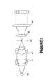
- FIG. 5illustrates a schematic diagram of another embodiment of the present invention.
- FIG. 5contains a light source 40 , a first optical element 41 , a second optical element 42 , a DOE 43 , a cross polarizer 44 and a large spherical lens 45 .
- a light beam from the light source 40passes through the first optical element 41 . After passing through the first optical element 42 , the light beam then feeds into the second optical element 43 . The light beam after passing through the second optical element 44 is then fed into the DOE 43 , through the cross polarizer 45 , and then passes through the large spherical lens 44 .
- the light beam from the light source 40is fed into the first and second optical elements 41 , 42 which can be two counter oriented plano-convex lenses in one embodiment.
- the first optical element 41collimates the light beam from the light source 40 .
- the second optical element 42focuses the collimated light beam and images it to a spot size.
- the focused light beamfeeds into the DOE 43 .
- the DOE 43can be a 1 ⁇ 3 row vector grating as an example embodiment and can be placed at the confocal distance of the combined focal length of the first and second optical elements 41 , 42 .
- the DOE 43scatters the focused light beam into three, diffraction orders in a cone of about 38 degrees, as an example.
- the angular separation of the first-order beams from the zeroth orderis about 19 degrees, as an example.
- the scattered beamsthen pass through a cross polarizer 45 .
- the cross polarizer 45is made up of two cross polarizers which are cut in half, and one-half of each was glued to the other.
- the cross polarizer 45when placed in front of the DOE 43 creates non-overlapping beams of different polarization in the far field, which eliminates any fringes.
- the scattered beamsare incident onto the large spherical lens 44 , which collimates the three beams into the far field.
- the beams when collimated in the far fieldgenerates a uniform intensity flat-top beam.
- the elements used in the optical pathare not required to be of a specific type.
- the elements in the pathcan be replaced with, but not limited to, a lens, a diffractive optical element, a holographic optical element, or Dammann grating that perform the same function.
Landscapes
- Physics & Mathematics (AREA)
- General Physics & Mathematics (AREA)
- Optics & Photonics (AREA)
- Electromagnetism (AREA)
- Engineering & Computer Science (AREA)
- Computer Networks & Wireless Communication (AREA)
- Signal Processing (AREA)
- Semiconductor Lasers (AREA)
Abstract
Description
Claims (30)
Priority Applications (1)
| Application Number | Priority Date | Filing Date | Title |
|---|---|---|---|
| US09/938,896US6487022B1 (en) | 2001-08-24 | 2001-08-24 | Transmitter using uniform intensity transmission for a wireless optical communication system |
Applications Claiming Priority (1)
| Application Number | Priority Date | Filing Date | Title |
|---|---|---|---|
| US09/938,896US6487022B1 (en) | 2001-08-24 | 2001-08-24 | Transmitter using uniform intensity transmission for a wireless optical communication system |
Publications (1)
| Publication Number | Publication Date |
|---|---|
| US6487022B1true US6487022B1 (en) | 2002-11-26 |
Family
ID=25472160
Family Applications (1)
| Application Number | Title | Priority Date | Filing Date |
|---|---|---|---|
| US09/938,896Expired - LifetimeUS6487022B1 (en) | 2001-08-24 | 2001-08-24 | Transmitter using uniform intensity transmission for a wireless optical communication system |
Country Status (1)
| Country | Link |
|---|---|
| US (1) | US6487022B1 (en) |
Cited By (15)
| Publication number | Priority date | Publication date | Assignee | Title |
|---|---|---|---|---|
| US20040264007A1 (en)* | 2003-06-26 | 2004-12-30 | Hoffnagle John Allen | Apparatus for achromatizing optical beams |
| EP1998215A1 (en) | 2007-05-31 | 2008-12-03 | Molecular Technology (MolTech) Gmbh | Achromatic optical system for beam shaping |
| US20090021832A1 (en)* | 2007-07-17 | 2009-01-22 | John Edwin Jackson | Wideband Diffraction Limited Optical Receiver |
| US20110019292A1 (en)* | 2009-07-24 | 2011-01-27 | Alexander Laskin | Achromatic Optical System for Beam Shaping |
| DE102010036521A1 (en)* | 2010-07-20 | 2012-01-26 | Era - Contact Gmbh | Device for transmitting data between two rail vehicles |
| DE102017115805A1 (en)* | 2017-07-13 | 2019-01-17 | LIMO GmbH | Device for beam shaping of laser radiation |
| CN110412613A (en)* | 2019-08-02 | 2019-11-05 | 上海木木机器人技术有限公司 | Measurement method, mobile device, computer equipment and storage medium based on laser |
| US10809193B2 (en) | 2018-04-06 | 2020-10-20 | Asml Netherlands B.V. | Inspection apparatus having non-linear optics |
| US11169385B2 (en) | 2016-01-13 | 2021-11-09 | Laservall Asia Co., Ltd. | Laser optical device and head |
| DE102012202117B4 (en) | 2011-02-14 | 2022-01-05 | Hamamatsu Photonics K.K. | Optical system for laser light shaping |
| CN114296245A (en)* | 2021-12-09 | 2022-04-08 | 华中光电技术研究所(中国船舶重工集团公司第七一七研究所) | Raman beam shaping device |
| CN115113409A (en)* | 2022-08-26 | 2022-09-27 | 成都莱普科技股份有限公司 | Linear flat-top light spot generation system, method and equipment based on Dammann grating |
| CN115194342A (en)* | 2022-09-19 | 2022-10-18 | 武汉引领光学技术有限公司 | Taper controllable laser grooving device and method |
| CN115826254A (en)* | 2023-02-14 | 2023-03-21 | 清华大学 | A flat-hat beam modulation method, system and storage medium |
| CN116505359A (en)* | 2023-03-16 | 2023-07-28 | 河南省启封新源光电科技有限公司 | Pulse cleaning orthogonal polarized wave generating device |
Citations (7)
| Publication number | Priority date | Publication date | Assignee | Title |
|---|---|---|---|---|
| US4530564A (en)* | 1980-08-18 | 1985-07-23 | Hughes Aircraft Company | Method and apparatus for production of holographic optical elements |
| US5237451A (en)* | 1989-11-17 | 1993-08-17 | Minnesota Mining And Manufacturing Company | Beam shaping system using diffraction |
| US5386426A (en)* | 1992-09-10 | 1995-01-31 | Hughes Aircraft Company | Narrow bandwidth laser array system |
| US5701373A (en)* | 1995-10-12 | 1997-12-23 | Sdl, Inc. | Method for improving the coupling efficiency of elliptical light beams into optical waveguides |
| US6088170A (en)* | 1997-01-28 | 2000-07-11 | Samsung Electronics Co., Ltd. | Optical system for shaping light beams and an optical pickup employing the same |
| US6128134A (en)* | 1997-08-27 | 2000-10-03 | Digital Optics Corporation | Integrated beam shaper and use thereof |
| US6339504B1 (en)* | 1998-11-10 | 2002-01-15 | Datalogic S.P.A. | Optical device and method for focusing a laser beam |
- 2001
- 2001-08-24USUS09/938,896patent/US6487022B1/ennot_activeExpired - Lifetime
Patent Citations (7)
| Publication number | Priority date | Publication date | Assignee | Title |
|---|---|---|---|---|
| US4530564A (en)* | 1980-08-18 | 1985-07-23 | Hughes Aircraft Company | Method and apparatus for production of holographic optical elements |
| US5237451A (en)* | 1989-11-17 | 1993-08-17 | Minnesota Mining And Manufacturing Company | Beam shaping system using diffraction |
| US5386426A (en)* | 1992-09-10 | 1995-01-31 | Hughes Aircraft Company | Narrow bandwidth laser array system |
| US5701373A (en)* | 1995-10-12 | 1997-12-23 | Sdl, Inc. | Method for improving the coupling efficiency of elliptical light beams into optical waveguides |
| US6088170A (en)* | 1997-01-28 | 2000-07-11 | Samsung Electronics Co., Ltd. | Optical system for shaping light beams and an optical pickup employing the same |
| US6128134A (en)* | 1997-08-27 | 2000-10-03 | Digital Optics Corporation | Integrated beam shaper and use thereof |
| US6339504B1 (en)* | 1998-11-10 | 2002-01-15 | Datalogic S.P.A. | Optical device and method for focusing a laser beam |
Cited By (24)
| Publication number | Priority date | Publication date | Assignee | Title |
|---|---|---|---|---|
| US6879448B2 (en) | 2003-06-26 | 2005-04-12 | International Business Machines Corporation | Apparatus for achromatizing optical beams |
| US20040264007A1 (en)* | 2003-06-26 | 2004-12-30 | Hoffnagle John Allen | Apparatus for achromatizing optical beams |
| EP1998215A1 (en) | 2007-05-31 | 2008-12-03 | Molecular Technology (MolTech) Gmbh | Achromatic optical system for beam shaping |
| US7961395B2 (en) | 2007-07-17 | 2011-06-14 | Northrop Grumman Systems Corporation | Wideband diffraction limited optical receiver |
| US20090021832A1 (en)* | 2007-07-17 | 2009-01-22 | John Edwin Jackson | Wideband Diffraction Limited Optical Receiver |
| US8023206B2 (en) | 2009-07-24 | 2011-09-20 | Molecular Technology Gmbh | Achromatic optical system for beam shaping |
| US20110019292A1 (en)* | 2009-07-24 | 2011-01-27 | Alexander Laskin | Achromatic Optical System for Beam Shaping |
| DE102010036521A1 (en)* | 2010-07-20 | 2012-01-26 | Era - Contact Gmbh | Device for transmitting data between two rail vehicles |
| US9048948B2 (en) | 2010-07-20 | 2015-06-02 | Era-Contact Gmbh | Device for transmitting data between two railway vehicles using optical radio relay |
| DE102012202117B4 (en) | 2011-02-14 | 2022-01-05 | Hamamatsu Photonics K.K. | Optical system for laser light shaping |
| US11169385B2 (en) | 2016-01-13 | 2021-11-09 | Laservall Asia Co., Ltd. | Laser optical device and head |
| DE102017115805A1 (en)* | 2017-07-13 | 2019-01-17 | LIMO GmbH | Device for beam shaping of laser radiation |
| DE102017115805B4 (en) | 2017-07-13 | 2019-02-28 | LIMO GmbH | Device for beam shaping of laser radiation |
| US11067815B2 (en) | 2017-07-13 | 2021-07-20 | LIMO GmbH | Apparatus for beam shaping of laser radiation |
| US10809193B2 (en) | 2018-04-06 | 2020-10-20 | Asml Netherlands B.V. | Inspection apparatus having non-linear optics |
| CN110412613B (en)* | 2019-08-02 | 2021-08-10 | 上海智蕙林医疗科技有限公司 | Laser-based measurement method, mobile device, computer device, and storage medium |
| CN110412613A (en)* | 2019-08-02 | 2019-11-05 | 上海木木机器人技术有限公司 | Measurement method, mobile device, computer equipment and storage medium based on laser |
| CN114296245A (en)* | 2021-12-09 | 2022-04-08 | 华中光电技术研究所(中国船舶重工集团公司第七一七研究所) | Raman beam shaping device |
| CN114296245B (en)* | 2021-12-09 | 2024-03-01 | 华中光电技术研究所(中国船舶重工集团公司第七一七研究所) | Raman beam shaping device |
| CN115113409A (en)* | 2022-08-26 | 2022-09-27 | 成都莱普科技股份有限公司 | Linear flat-top light spot generation system, method and equipment based on Dammann grating |
| CN115113409B (en)* | 2022-08-26 | 2022-12-30 | 成都莱普科技股份有限公司 | Linear flat-top light spot generation system, method and equipment based on Dammann grating |
| CN115194342A (en)* | 2022-09-19 | 2022-10-18 | 武汉引领光学技术有限公司 | Taper controllable laser grooving device and method |
| CN115826254A (en)* | 2023-02-14 | 2023-03-21 | 清华大学 | A flat-hat beam modulation method, system and storage medium |
| CN116505359A (en)* | 2023-03-16 | 2023-07-28 | 河南省启封新源光电科技有限公司 | Pulse cleaning orthogonal polarized wave generating device |
Similar Documents
| Publication | Publication Date | Title |
|---|---|---|
| US6487022B1 (en) | Transmitter using uniform intensity transmission for a wireless optical communication system | |
| US7440174B2 (en) | Coherent fiber diffractive optical element beam combiner | |
| US7468832B2 (en) | Method and system for coherent beam combining using an integrated diffractive beam combiner and sampler | |
| US7436588B2 (en) | Method and system for hybrid coherent and incoherent diffractive beam combining | |
| US7339727B1 (en) | Method and system for diffractive beam combining using DOE combiner with passive phase control | |
| US7346085B1 (en) | Multi-stage method and system for coherent diffractive beam combining | |
| US11681152B2 (en) | Coherent beam combining (CBC) fiber laser amplifier system | |
| US20070291813A1 (en) | Coupling devices and methods for stacked laser emitter arrays | |
| US20060280209A1 (en) | Beam combining methods and devices with high output intensity | |
| US11294192B2 (en) | Optically monolithic beam shaper array with compact tiles | |
| US11681151B2 (en) | Hybrid coherent beam combining (CBC) and spectral beam combining (SBC) fiber laser amplifier system | |
| US20090153968A1 (en) | Spectral beam combination using broad bandwidth lasers | |
| CN112513717A (en) | Device, laser system and method for combining coherent laser beams | |
| US11698537B2 (en) | Spectrally combined fiber laser amplifier system and method | |
| US11932567B2 (en) | System and method for fabricating an optical element | |
| US7212554B2 (en) | Wavelength stabilized laser | |
| US20110063701A1 (en) | Digital optical, planar holography system and method for improving brightness of light beams | |
| US20220360036A1 (en) | Apparatus, laser system and method for combining coherent laser beams | |
| US11876338B2 (en) | Device for combining at least two laser beams | |
| WO2008045652A2 (en) | Method and system for diffractive beam combining using doe combiner with passive phase control |
Legal Events
| Date | Code | Title | Description |
|---|---|---|---|
| AS | Assignment | Owner name:TERABEAM CORPORATION, WASHINGTON Free format text:ASSIGNMENT OF ASSIGNORS INTEREST;ASSIGNOR:OKOROGU, ALBERT O.;REEL/FRAME:012562/0120 Effective date:20011231 | |
| STCF | Information on status: patent grant | Free format text:PATENTED CASE | |
| CC | Certificate of correction | ||
| FPAY | Fee payment | Year of fee payment:4 | |
| FEPP | Fee payment procedure | Free format text:PAYOR NUMBER ASSIGNED (ORIGINAL EVENT CODE: ASPN); ENTITY STATUS OF PATENT OWNER: LARGE ENTITY | |
| AS | Assignment | Owner name:PERTEX TELECOMMUNICATION LLC, DELAWARE Free format text:ASSIGNMENT OF ASSIGNORS INTEREST;ASSIGNOR:TERABEAM CORPORATION;REEL/FRAME:021556/0960 Effective date:20080523 | |
| FEPP | Fee payment procedure | Free format text:PAYOR NUMBER ASSIGNED (ORIGINAL EVENT CODE: ASPN); ENTITY STATUS OF PATENT OWNER: LARGE ENTITY Free format text:PAYER NUMBER DE-ASSIGNED (ORIGINAL EVENT CODE: RMPN); ENTITY STATUS OF PATENT OWNER: LARGE ENTITY | |
| FPAY | Fee payment | Year of fee payment:8 | |
| FPAY | Fee payment | Year of fee payment:12 | |
| AS | Assignment | Owner name:OL SECURITY LIMITED LIABILITY COMPANY, DELAWARE Free format text:MERGER;ASSIGNOR:PERTEX TELECOMMUNICATION LLC;REEL/FRAME:037392/0187 Effective date:20150826 |