US6487020B1 - Volumetric three-dimensional display architecture - Google Patents
Volumetric three-dimensional display architectureDownload PDFInfo
- Publication number
- US6487020B1 US6487020B1US09/404,046US40404699AUS6487020B1US 6487020 B1US6487020 B1US 6487020B1US 40404699 AUS40404699 AUS 40404699AUS 6487020 B1US6487020 B1US 6487020B1
- Authority
- US
- United States
- Prior art keywords
- display system
- light
- screen
- elements
- lenticular
- Prior art date
- Legal status (The legal status is an assumption and is not a legal conclusion. Google has not performed a legal analysis and makes no representation as to the accuracy of the status listed.)
- Expired - Lifetime
Links
- 230000007246mechanismEffects0.000claimsabstractdescription6
- 238000005286illuminationMethods0.000claimsdescription24
- 230000003287optical effectEffects0.000claimsdescription21
- 239000000463materialSubstances0.000claimsdescription10
- 230000001427coherent effectEffects0.000claimsdescription4
- 238000000034methodMethods0.000description5
- 230000000737periodic effectEffects0.000description5
- 239000013598vectorSubstances0.000description4
- 230000008901benefitEffects0.000description3
- 238000005516engineering processMethods0.000description3
- 238000003384imaging methodMethods0.000description3
- 230000004308accommodationEffects0.000description2
- 238000009125cardiac resynchronization therapyMethods0.000description2
- 230000003247decreasing effectEffects0.000description2
- 230000000694effectsEffects0.000description2
- 238000004519manufacturing processMethods0.000description2
- 230000009471actionEffects0.000description1
- 238000003491arrayMethods0.000description1
- 230000004888barrier functionEffects0.000description1
- 230000003139buffering effectEffects0.000description1
- 238000010276constructionMethods0.000description1
- 230000008878couplingEffects0.000description1
- 238000010168coupling processMethods0.000description1
- 238000005859coupling reactionMethods0.000description1
- 238000011161developmentMethods0.000description1
- 230000018109developmental processEffects0.000description1
- 230000004438eyesightEffects0.000description1
- 239000000835fiberSubstances0.000description1
- 230000003760hair shineEffects0.000description1
- 239000002184metalSubstances0.000description1
- 239000000203mixtureSubstances0.000description1
- 230000002688persistenceEffects0.000description1
- 230000005855radiationEffects0.000description1
- 238000009877renderingMethods0.000description1
- 238000009416shutteringMethods0.000description1
- 230000011664signalingEffects0.000description1
- 238000009987spinningMethods0.000description1
- 230000009466transformationEffects0.000description1
Images


Classifications
- G—PHYSICS
- G09—EDUCATION; CRYPTOGRAPHY; DISPLAY; ADVERTISING; SEALS
- G09G—ARRANGEMENTS OR CIRCUITS FOR CONTROL OF INDICATING DEVICES USING STATIC MEANS TO PRESENT VARIABLE INFORMATION
- G09G3/00—Control arrangements or circuits, of interest only in connection with visual indicators other than cathode-ray tubes
- G09G3/02—Control arrangements or circuits, of interest only in connection with visual indicators other than cathode-ray tubes by tracing or scanning a light beam on a screen
- G09G3/025—Control arrangements or circuits, of interest only in connection with visual indicators other than cathode-ray tubes by tracing or scanning a light beam on a screen with scanning or deflecting the beams in two directions or dimensions
- G—PHYSICS
- G02—OPTICS
- G02B—OPTICAL ELEMENTS, SYSTEMS OR APPARATUS
- G02B30/00—Optical systems or apparatus for producing three-dimensional [3D] effects, e.g. stereoscopic images
- G02B30/20—Optical systems or apparatus for producing three-dimensional [3D] effects, e.g. stereoscopic images by providing first and second parallax images to an observer's left and right eyes
- G02B30/26—Optical systems or apparatus for producing three-dimensional [3D] effects, e.g. stereoscopic images by providing first and second parallax images to an observer's left and right eyes of the autostereoscopic type
- G02B30/27—Optical systems or apparatus for producing three-dimensional [3D] effects, e.g. stereoscopic images by providing first and second parallax images to an observer's left and right eyes of the autostereoscopic type involving lenticular arrays
- G—PHYSICS
- G09—EDUCATION; CRYPTOGRAPHY; DISPLAY; ADVERTISING; SEALS
- G09G—ARRANGEMENTS OR CIRCUITS FOR CONTROL OF INDICATING DEVICES USING STATIC MEANS TO PRESENT VARIABLE INFORMATION
- G09G3/00—Control arrangements or circuits, of interest only in connection with visual indicators other than cathode-ray tubes
- G09G3/001—Control arrangements or circuits, of interest only in connection with visual indicators other than cathode-ray tubes using specific devices not provided for in groups G09G3/02 - G09G3/36, e.g. using an intermediate record carrier such as a film slide; Projection systems; Display of non-alphanumerical information, solely or in combination with alphanumerical information, e.g. digital display on projected diapositive as background
- G09G3/002—Control arrangements or circuits, of interest only in connection with visual indicators other than cathode-ray tubes using specific devices not provided for in groups G09G3/02 - G09G3/36, e.g. using an intermediate record carrier such as a film slide; Projection systems; Display of non-alphanumerical information, solely or in combination with alphanumerical information, e.g. digital display on projected diapositive as background to project the image of a two-dimensional display, such as an array of light emitting or modulating elements or a CRT
- G—PHYSICS
- G09—EDUCATION; CRYPTOGRAPHY; DISPLAY; ADVERTISING; SEALS
- G09G—ARRANGEMENTS OR CIRCUITS FOR CONTROL OF INDICATING DEVICES USING STATIC MEANS TO PRESENT VARIABLE INFORMATION
- G09G3/00—Control arrangements or circuits, of interest only in connection with visual indicators other than cathode-ray tubes
- G09G3/001—Control arrangements or circuits, of interest only in connection with visual indicators other than cathode-ray tubes using specific devices not provided for in groups G09G3/02 - G09G3/36, e.g. using an intermediate record carrier such as a film slide; Projection systems; Display of non-alphanumerical information, solely or in combination with alphanumerical information, e.g. digital display on projected diapositive as background
- G09G3/003—Control arrangements or circuits, of interest only in connection with visual indicators other than cathode-ray tubes using specific devices not provided for in groups G09G3/02 - G09G3/36, e.g. using an intermediate record carrier such as a film slide; Projection systems; Display of non-alphanumerical information, solely or in combination with alphanumerical information, e.g. digital display on projected diapositive as background to produce spatial visual effects
- G—PHYSICS
- G09—EDUCATION; CRYPTOGRAPHY; DISPLAY; ADVERTISING; SEALS
- G09G—ARRANGEMENTS OR CIRCUITS FOR CONTROL OF INDICATING DEVICES USING STATIC MEANS TO PRESENT VARIABLE INFORMATION
- G09G3/00—Control arrangements or circuits, of interest only in connection with visual indicators other than cathode-ray tubes
- G09G3/02—Control arrangements or circuits, of interest only in connection with visual indicators other than cathode-ray tubes by tracing or scanning a light beam on a screen
- H—ELECTRICITY
- H04—ELECTRIC COMMUNICATION TECHNIQUE
- H04N—PICTORIAL COMMUNICATION, e.g. TELEVISION
- H04N13/00—Stereoscopic video systems; Multi-view video systems; Details thereof
- H04N13/30—Image reproducers
- H04N13/302—Image reproducers for viewing without the aid of special glasses, i.e. using autostereoscopic displays
- H04N13/305—Image reproducers for viewing without the aid of special glasses, i.e. using autostereoscopic displays using lenticular lenses, e.g. arrangements of cylindrical lenses
- H—ELECTRICITY
- H04—ELECTRIC COMMUNICATION TECHNIQUE
- H04N—PICTORIAL COMMUNICATION, e.g. TELEVISION
- H04N13/00—Stereoscopic video systems; Multi-view video systems; Details thereof
- H04N13/30—Image reproducers
- H04N13/349—Multi-view displays for displaying three or more geometrical viewpoints without viewer tracking
- H—ELECTRICITY
- H04—ELECTRIC COMMUNICATION TECHNIQUE
- H04N—PICTORIAL COMMUNICATION, e.g. TELEVISION
- H04N13/00—Stereoscopic video systems; Multi-view video systems; Details thereof
- H04N13/30—Image reproducers
- H04N13/388—Volumetric displays, i.e. systems where the image is built up from picture elements distributed through a volume
- H04N13/393—Volumetric displays, i.e. systems where the image is built up from picture elements distributed through a volume the volume being generated by a moving, e.g. vibrating or rotating, surface
- H—ELECTRICITY
- H04—ELECTRIC COMMUNICATION TECHNIQUE
- H04N—PICTORIAL COMMUNICATION, e.g. TELEVISION
- H04N13/00—Stereoscopic video systems; Multi-view video systems; Details thereof
- H04N13/20—Image signal generators
- H04N13/286—Image signal generators having separate monoscopic and stereoscopic modes
- H—ELECTRICITY
- H04—ELECTRIC COMMUNICATION TECHNIQUE
- H04N—PICTORIAL COMMUNICATION, e.g. TELEVISION
- H04N13/00—Stereoscopic video systems; Multi-view video systems; Details thereof
- H04N13/30—Image reproducers
- H04N13/398—Synchronisation thereof; Control thereof
Definitions
- the inventionrelates generally to electronic display technology and more specifically to volumetric three-dimensional displays.
- KetchpelU.S. Pat. No. 3,140,4105
- His systemutilizes a phosphorescent rotating screen that is illuminated by a fixed electron gun. His approach, however, is characterized by “dead zone” regions which are not addressable or accessible by the illumination source. For example, when the angle between the screen's plane and the impinging illumination beam is small, it is difficult to draw imagery of high detail. In such regions, the imaging volume has picture elements (i.e., voxels) that are plagued with low spatial accuracy.
- Schwarz and Blundellattempted to solve this problem by using a similar phosphorescent screen system and illuminating it with two electron guns, each responsible for illuminating the screen during different angular segments ( IEEE Proc.—Optoelectron., Vol. 141, No. 5, October 1994, pp. 336-344). This helps eliminate the dead zone but requires duplicate illumination, computation, and aiming systems and circuitry.
- BatchkoU.S. Pat. No. 5,148,310
- the scanning systemis positioned to always illuminate the rotating screen from a direction nearly perpendicular to the screen.
- His approachwhich requires the spinning of a set of mirrors at least one of which is an off-axis mirror, helps reduce the scanning dead zone.
- his systemlike the systems of Ketchpel, Schwarz and Blundell, and many others, is a vector-based scanning system which employs a computationally intensive technology that is known to flicker when drawing complex imagery.
- Tsao et al.(U.S. Pat. No. 5,754,147) disclose a volumetric display which, like the Batchko technology, attaches an off-axis mirror to the rotating display unit. They describe a display that is made of three subunits, namely, an optical data generator, an optical interfacing unit, and a rotating unit with display means.
- Their optical data unitincludes an image projector whose generated images are projected into a complex of coaxially rotating mirrors. The mirrors rotate at a different speed than the rotating display screen. They relay light to another mirror, which rotates off-axis with the display screen at approximately 10 Hz.
- Their optical interfacing unitincludes 5 to 10 miniature mirrors.
- Garcia Jr., et al(U.S. Pat. No. 5,042,909) employed a rotating screen illuminated by vector-scanned laser light. As their screen rotates, a system of computer-controlled scanners steers laser light onto it. This technique exhibits some of the same characteristics of vector-based displays. For instance, only a low percentage of the addressable volume may be used in a given image.
- FavaloraU.S. Pat. No. 5,936,767, entitled “Multiplanar Autostereoscopic Imaging System,” and incorporated herein by reference discloses a raster-based imaging system that is computationally simpler than the vector scanned systems and uses fewer moving parts than some of the systems described above.
- volumetric 3-D displaysprovide imagery with nearly every depth cue, most notably convergence (i.e., the viewer's eyes rotate inwards as a function of nearness) and accommodation (i.e., the viewer's lenses focus farther as function of depth).
- all known multiplanar, 3-D displays, including those described abovehave been unable to render imagery which exhibits occlusion (i.e., the tendency of objects in the foreground to block those in the background). This is because the illuminated regions are naturally transparent.
- the resulting imagerypossesses a ghost-like transparent quality which prevents the viewer from enjoying the occlusion of objects placed in front of each other.
- occlusionis produced in the displayed image by providing the rendering software with knowledge of the viewer's position. If the rendering software that computes the image slices that are to be displayed is capable of hidden surface removal, it can render a view appropriate for the viewer's position.
- the position informationmay be input manually or acquired with existing head-tracking or eye-tracking systems. However, for any additional viewer located at another position different from the first viewer's position, the imagery will appear confusing because the occlusion will be incorrect. Although steps can be taken to lightly render the “hidden surfaces,” the effect will still be incomplete.
- the 3-D displaymust continue to provide cues for convergence and accommodation.
- the inventionis a display system including a lenticular screen; a support assembly movably supporting the lenticular screen; and a drive mechanism which during operation causes the lenticular screen to repeatedly sweep through a volume of space.
- the lenticular screenis helical in shape and includes an array of cylindrically-shaped lens elements or spherically-shaped lens elements, or some combination thereof.
- the arrayis an M by N array.
- the support assemblydefines an axis of rotation for the screen.
- the screenhas an axis of symmetry and is mounted in the support assembly with axis of rotation and the axis of symmetry being collinear.
- the drive mechanism during operationrotates the screen continually about the axis of rotation.
- the lenticular screenis translucent.
- the screenis made up of an array of lenticular elements and a sheet of material having a back surface and a front surface, wherein the array of lenticular elements is on only the front surface.
- the back surface of the sheet of materialis smooth.
- the inventionis a lenticular screen that is translucent and helical in shape.
- the inventionis a volumetric display including ganged SLMs within the image generator.
- the ganged SLMsare operated sequentially, each one handling a different projected image slice.
- Systems embodying the inventionexhibit one or more of the following advantages in comparison to prior art systems. They provide a 3-D display which can exhibit the occlusion of imagery using variable transparency, for one viewer and for multiple viewers. They can provide realistic imagery which does not suffer from constant transparency. They are economical and do not require cumbersome reflective scanning means which rotate quickly with respect to the display unit. They do not include a large number of fixed beam-steering optics to ensure that the illumination reaches the final scanning member. They provide a 3-D display with a minimum of moving mechanical elements. They do not use duplicate illumination sources, which require additional computational effort and hardware to support. They do not require coherent illumination, which is can be costly and dangerous. They do not use screen geometries which introduce significant dark regions known as dead zones.
- the screendoes not require specialized and expensive computational systems. They can provide multicolor imagery without undue cost. In addition, they allow a design flexibility in the which the screen can either be used in a “projection screen” mode, such as a diffusive surface, or a “non-projection screen” mode, such as a mirror which redirects light from an internal imagery source.
- a “projection screen” modesuch as a diffusive surface
- a “non-projection screen” modesuch as a mirror which redirects light from an internal imagery source.
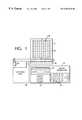
- FIG. 1shows the key components of a generalized volumetric display embodying the invention
- FIG. 2is a schematic representation of a lenticular screen
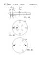
- FIGS. 3A-Dillustrate the operation of the lenticular display
- FIG. 4illustrates various designs of lenticular lens elements
- FIG. 5shows a schematic representation of an emissive lenticular display
- FIG. 6shows an example of an emissive lenticular display in which the front lenses of the emissive elements include light directing portions
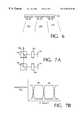
- FIG. 7Ashows a ganged arrangement of SLMs
- FIG. 7Bshows waveforms for the transmissivities of the optical shutters used in the arrangement of FIG. 7A;
- FIGS. 8A-Cshow mechanical shutter systems for selecting which SLM provides the projected image
- FIG. 9shows a volumetric display system that uses raster scanning and a ganged arrangement of SLMs.
- FIG. 1An illustrative embodiment of a volumetric display is shown in FIG. 1.
- a planar, rectangular lenticular screen 40 inside a viewport 5undergoes periodic motion during which it repeatedly sweeps out a volume of space.
- a control unit 10monitors the orientation of screen 40 and instructs an image generator 15 to project imagery into the viewport and onto screen 40 .
- the screen's periodic motionis sufficiently frequent to enable a viewer (or viewers) to perceive volume-filling 3-D imagery.
- a variety of components and structuresmay play the roles of viewport 5 , control unit 10 , and image generator 15 . Considerations of cost and use will typically dictate the resolution, type, precision, and mode of manufacture of these units.
- screen 40is mounted so that its axis of symmetry coincides with an axis of rotation and a motor 45 sets screen 40 into rapid rotation at approximately 20 revolutions per second about the axis of rotation.
- Control unit 10senses the angular position and frequency of the screen and sends image data to image generator 15 .
- an illumination unit 20illuminates a spatial light modulator (SLM) 25 which directs reflected light up towards projection optics 30 .
- SLM 25is a two-dimensional array of light control elements each of which either reflects impinging light from illumination unit 20 or allows that light to pass through depending upon signals applied to the SLM. In other words, SLM 25 reflects an image towards projection optics 30 corresponding to the data supplied by the control unit.
- the illumination sourceis non-collimated and incoherent, so the projection optics also include elements that provide a sharp focus on the screen as well as an arrangement of mirrors 35 which maintain a fixed relationship with the screen and are designed to project the image onto the screen.
- the projection system used in the described embodimentis similar to others used in the prior art. The reader is referred to the prior art for additional details. See, for example, “New Display Gives Realistic 3-D Effect,” Aviation Week, Oct. 31, 1960, pp. 66-67.
- the viewer or viewerswill be able to see volume-filling imagery in the viewport 5 from nearly any angle. And because the screen is a lenticular screen, images can be generated which show the appropriate occlusion for different viewing angles.
- the volumetric display systemcan use image-redirection optics, such as a rotating dove prism or K-mirror, to rotate the image at the same speed as the rotating screen and thereby generate a stationary image on the screen.
- image data fed to the image generatormay be rotated computationally by the control unit.
- Either approachallows each image frame (many of which are drawn per update, e.g. 256) to be projected with the correct orientation and scaling with respect to the viewing screen 40 . If the latter approach is used, the computational transformation can be performed quickly, especially if precomputed lookup tables are used.
- the rendering and display techniques for accomplishing thisare known in the art. Thus, such techniques will not be described here but rather the reader is referred to existing readily available public sources providing such details.
- Lenticular screen 40includes an array of lenticular lenses 44 on at least one of its surfaces.
- Lenticular screen 40enables the image generator to project different imagery for different viewing angles.
- the array of lenticular lenses 44enables viewers at different viewpoints to see different images. If properly registered imagery is projected onto the screen, the viewport will provide volume-filling imagery, which, as usual, provides correct perspective and parallax, and which also has variable transparency so that objects may occlude each other. This requires computing image data from several viewpoints for each projected frame.
- lenticular lenses and lens arraysare well known in the art, a brief description of how they work will be provided.
- a more widely known embodiment of a lenticular lens arrayis a lenticular lens sheet. It includes a sheet with a plurality of adjacent, parallel, elongated, and partially cylindrical lenses and multiple (e.g. two) interleaved images on the sheet.
- the plurality of lensesenables the multiple interleaved images to be displayed on the underlying sheet but only one of the images will be visible from any given vantage point above the sheet.
- FIG. 2presents a schematic side view of a lenticular lens sheet 52 with a plurality of lens elements 54 ( 1 - 3 ).
- the image on the underlying sheetis represented by pixels 56 - 58 .
- three image pixels, identified by suffixes “a”, “b”, and “c”, respectively,are shown under each lens element 54 .
- lens element 54 ( 1 )because of its focusing ability, allows that person to only see light from pixel 56 a. That is, of the light which lens element 54 ( 1 ) collects, it only sends toward the person at location “A” that light which is collected from pixel element 56 a. The rest of the light which lens element 54 ( 1 ) collects from other locations under the lens is sent off in other directions and will not be seen by a person a location “A”. For similar reasons, a person at location “B” only sees light emanating from pixel 56 b, but does not see light emanating from other locations under lens element 54 ( 1 ).
- FIGS. 3A-Dillustrate how the revolving lenticular display system works in accordance with the principles just described. It shows in schematic form, a lenticular display screen 71 with an array of lenses 73 on one surface.
- each lensis characterized by four viewing zones, labeled “1”, “2”, “3”, and “4”.
- each viewing zoneilluminates a continuous angle. That is, a viewer positioned anywhere within that zone (e.g. zone 1 ) should be able to view the appropriate pixel associated with that zone, as previously described.
- the observercannot see pixels associated with the other zones.
- screen 71is rotating in a counterclockwise direction and as an observer at location 75 looks at the screen, zones 1 - 4 will pass by in that order.
- FIG. 3Aillustrates one rotational position of the display screen in which the observer sees light for zone 1 .
- zone 1like the other zones, represents a range of rotation during which the viewer sees the image information that is projected onto the locations on the screen that are visible in that zone. If we assume that a new image slice is projected onto the display screen every 1° of rotation and that each zone is 25° wide, then the observer at location 75 will see about 25 successive individual image slices when zone 1 sweeps by. Each new image slice is separated from the last one by an amount attributable to 1° of rotation of the screen.
- the image slices that the controller causes to be projected onto the pixels for zone 1must be appropriately rendered for observation at the viewing position of observer 75 .
- an observer at location 77will be seeing images from zone 4 at the same time that the observer at location 75 is seeing images for zone 1 .
- another set of images, rendered from the perspective of location 77must be displayed on the pixels associated with zone 4 at the same time that the other images are being displayed for zone 1 .
- neither observerwill see the other images because of the selecting ability of the lenticular lenses.
- these other image slicescan be displayed concurrently with the image slices of the other perspectives.
- the number of image slices that are projected onto the screen during a rotationis unrelated to the number of viewing zones.
- approximately 200 image slicesneed to be projected for viewers in 4 or more zones.
- the lenticular screenwill be characterized by discrete viewing zones which “blend” into each other. That is, there should be no cutoff of perceived illumination between neighboring zones.
- a “lenticular lens array” and a “lenticular screen”are meant to cover all embodiments of a lens element array which provide the type of directional selection of the underlying image information that was described above.
- the lens elementscan be cylindrically-shaped, as mentioned earlier, or they can be spherically-shaped so as to provide an image discrimination function in at least two orthogonal directions within a plane parallel to the plane of the array.
- the elementsneed not be conventional lens elements; they can be any optical element, including holographic optical elements, which provide the same type of functionality described above.
- Lenticular screen 40is made of a translucent material or at least a material that has a translucent backside surface which can be illuminated by the impinging light and the illuminated portion will be visible.
- the array of lenticular lens elementsis on the front surface of the screen.
- the image lightis projected onto the backside at the appropriate pixel locations. And the resulting images are viewed from the various viewing positions in front of the screen.
- the described embodimentemploys a planar, rectangular screen, other geometries can also be used.
- the screenmay have a planar circular shape or some other shape.
- the screenmay have an axis of symmetry, or if it is does, that the axis of symmetry also be the axis of rotation.
- the motion imparted to the screenneed not be strictly rotary. The only essential requirement is that the imparted motion cause the screen to repeatedly sweep out a fixed volume of space.
- the screencould also have a more complex shape such as helical, as described elsewhere in the public literature.
- helicala more complex shape
- MortonU.S. Pat. No. 4,922,336 which describes one type of helical screen that is “formed of a single turn of a constant radius spiral, such as a single turn of an ‘Archimedes screw’”.
- Other designs of the helical screenare, of course, also possible.
- anamorphic lensthat helps achieve better focus would also be desirable.
- the design and construction of such as anamorphic lensis also generally known in the art. Again, see Morton who discloses the use of a co-rotating coaxial anamorphic lens to aid in focusing on his helical screen. His lens was made of many tiny elements, each of which is responsible for one voxel on the surface of the helical screen.
- HOEholographic optical element
- the lenticular screenmay be fashioned out of a collection of “directional slats,” such as the striped metal pattern found covering traffic lights so that a car in a given lane can see the stop/go light intended only for that lane.
- directional slatssuch as the striped metal pattern found covering traffic lights so that a car in a given lane can see the stop/go light intended only for that lane.
- a similar dense 2-D array of such slatscan be created into a lenticular screen.
- the screen geometries that could be used in the lenticular displaycan also be improved by endowing them with a non-rectangular cross-section, as disclosed in U.S. Ser. No. 09/318,086, incorporated herein by reference.
- the screen when viewed from the sidecan have a diamond-shaped cross-section, which will help eliminate the dark region formed wherever the viewer is looking at the edge of the projection screen.
- the lenticular lens elements 91 on lenticular screen 93may be vertical, horizontal, spherical, or a combination of these. Or they may be implemented by a louver element as disclosed by Kollin's in U.S. Pat. No. 4,853,769, or by any other known means of barrier grids. Also, they may employ a holographic optical element (HOE) as disclosed by Trayner, D. J. and Orr, E., “Developments in autostereoscopic Displays using Holographic Optical Elements,” in Stereoscopic Displays and Virtual Reality Systems IV, Scott S. Fisher, John O. Merritt, Mark T. Bolas, Editors, Proceedings of. SPIE Vol. 3012, 167-174 (1997).
- HOEholographic optical element
- the imagery intended for different viewing zonesmay be interleaved on a pixel-by-pixel basis.
- the 2-D display screenmay be organized into a periodic structure of pixel groups, each of which is comprised of a pixel intended to be seen from a given viewing zone. Or, the 2-D display screen may be arranged in a series of vertical or horizontal alternating bands.
- the pixels for each viewpointmay also be displayed in a time-varying manner. That is, if the directional shutter or lenticular screen has time-varying directional properties, such as that stipulated in Kollin's U.S. Pat. No. 4,853,769, the 2-D imagery may cycle in time through the viewpoint-specific illustrations. Or, there may be a combination of both—a time-varying series of illumination patterns which are also built out of direction-specific subpixels.
- the lenticular or multi-viewzone swept displaymay also be an emissive display 211 such as a backlit LCD panel or a tight array of LEDs, as illustrated in FIG. 5 .
- the displayis emissive (e.g. see U.S. Pat. No. 4,160,973), the illumination information needs to be passed into a rotating structure. This may be achieved using conductive brushes, capacitive coupling, RF signaling, or the use of phototransistors.
- an emissive, multi-viewzone swept displayis a periodic structure of emissive element 213 whose front surfaces direct light in a small angle zones 230 , 231 , and 232 .
- Theymay be LEDs or LCD pixels with elements attached to them, for example, or may be comprised of a tight bundle of fiber optic elements (e.g. see U.S. Pat. No. 5,082,350.).
- the swept lenticular screen displays described hereinmay be operated in modes which provide an arbitrary number of viewpoints limited only by the number of different viewing angles that are provided by the lenticular elements. Furthermore, if the display system is given information on the position of the viewers, it can operate in a mode which only provides imagery for those positions. Using that approach may be useful for increasing brightness and decreasing computational load.
- the image generatorcan provide increased resolution and allow for the use of lower cost components.
- the image generatorcan employ multiple, buffered SLMs. While one unit is displaying an image slice onto the revolving screen, the other is receiving image data for the display of the next image slice.
- several slow and/or low-resolution illumination sourcese.g. SLMs
- SLMsslow and/or low-resolution illumination sources
- FIGS. 7A and 8AIllustrative embodiments of this approach are shown in FIGS. 7A and 8A.
- SLM 70 and SLM 75both of which are illuminated by an illumination source that is not shown, handle alternate 2-D slices of the final 3-D image that is projected on the revolving display screen.
- Optical shutters 80 and 85sequentially pass light from the SLMs to corresponding beam combining optics 90 and 95 (e.g. beam splitters). The passed light at any moment is in image beam 100 .
- FIG. 7Bshows two waveforms representing typical % transmissivities as a function of time for the two optical shutters 80 and 85 .
- Waveform # 1is for optical shutter 80 and waveform # 2 is for optical shutter 85 .
- ganging together portions of or the entirety of one or more 1- or 2-D SLMs (or, for that matter, other light emitters or modulators)can result in a higher resolution than would ordinarily be available from single, slow modulators or emitters.
- FIG. 8Aillustrates another embodiment which improves upon the ganged SLM concept, at least in terms of cost. It uses a slotted rotating disk 105 to perform the optical shuttering. This will decrease both system cost and complexity, especially if the rotating shutter is connected physically to the rotating screen.
- one or more SLMs or light sources 70 and 75are loaded with appropriate image data from the control unit.
- the imagesare sequential slices of the light to be projected onto the rotating screen.
- the slotted rotating shutter 105allows light from the SLMs to pass through sequentially, through an optical relay 110 (typically one or more mirrors 101 and beam-combining optics 103 ) towards a final mirror 115 which shuttles the imagery 100 toward the final projection optics and the rotating screen.
- the rotating shuttercan be physically connected to the other rotating components.
- the shuttermay be constructed of a variety of punched holes, inset lenses, slits, or other appropriate elements.
- the shutter actionmay be incorporated into the HOE which ordinarily would be performing helical focusing tasks.
- the SLMs or light sourcesmay be on the same, opposite, or other locations relative to the axis of rotation (as illustrated in FIG. 8 C). For example, if 256 slots are punched into the rotating disk, it may rotate at the same speed as the projection screen and HOE to provide 256 slices through the 3-D volume. If fewer slots are used than there are image slices, then the shutter disk must rotate more frequently than the projection screen.
- slotted flat diskdifferent geometries can be used other than a slotted flat disk.
- the slots on the vertical wallgate images from SLMs located outside of and parallel to the wall.
- the gated imagesare sent to an optical assembly located within the plate and that optical assembly redirects the images to the lenticular screen.
- FIG. 9illustrates the use of high-speed 1-D SLMs or light sources (such as a linear array of emitters). They may be ganged, as above, or simply used sequentially and scanned. Or, typically, one (for monochrome) or three (for multicolor) imagery may be used to perform high-speed modulation of an illumination source.
- the illustrationdepicts a single 1-D SLM which modulates laser illumination that is then scanned onto a rotating plane.
- this geometrymay be changed to include a variety of different screen or scanning methods (for example, a vibrating mirror scanner onto a helical screen.)
- SLMscan include 1-D SLMs, 2-D SLMs, regions of 1- or 2-D SLMs, or various other radiation emitters or modulators.
Landscapes
- Engineering & Computer Science (AREA)
- Physics & Mathematics (AREA)
- General Physics & Mathematics (AREA)
- Computer Hardware Design (AREA)
- Theoretical Computer Science (AREA)
- Multimedia (AREA)
- Signal Processing (AREA)
- Optics & Photonics (AREA)
- Overhead Projectors And Projection Screens (AREA)
Abstract
Description
Claims (26)
Priority Applications (1)
| Application Number | Priority Date | Filing Date | Title |
|---|---|---|---|
| US09/404,046US6487020B1 (en) | 1998-09-24 | 1999-09-23 | Volumetric three-dimensional display architecture |
Applications Claiming Priority (2)
| Application Number | Priority Date | Filing Date | Title |
|---|---|---|---|
| US10161798P | 1998-09-24 | 1998-09-24 | |
| US09/404,046US6487020B1 (en) | 1998-09-24 | 1999-09-23 | Volumetric three-dimensional display architecture |
Publications (1)
| Publication Number | Publication Date |
|---|---|
| US6487020B1true US6487020B1 (en) | 2002-11-26 |
Family
ID=22285581
Family Applications (1)
| Application Number | Title | Priority Date | Filing Date |
|---|---|---|---|
| US09/404,046Expired - LifetimeUS6487020B1 (en) | 1998-09-24 | 1999-09-23 | Volumetric three-dimensional display architecture |
Country Status (5)
| Country | Link |
|---|---|
| US (1) | US6487020B1 (en) |
| EP (1) | EP1116201A1 (en) |
| JP (1) | JP2002525686A (en) |
| CA (1) | CA2345386A1 (en) |
| WO (1) | WO2000017844A1 (en) |
Cited By (33)
| Publication number | Priority date | Publication date | Assignee | Title |
|---|---|---|---|---|
| US20020011969A1 (en)* | 2000-06-07 | 2002-01-31 | Lenny Lipton | Autostereoscopic pixel arrangement techniques |
| US20040085260A1 (en)* | 2002-11-05 | 2004-05-06 | Mcdavid Louis C. | Multi-lingual display apparatus and method |
| US6765566B1 (en)* | 1998-12-22 | 2004-07-20 | Che-Chih Tsao | Method and apparatus for displaying volumetric 3D images |
| US20040189957A1 (en)* | 2003-03-25 | 2004-09-30 | Shpizel Matvey B | Light projection device |
| US20040212589A1 (en)* | 2003-04-24 | 2004-10-28 | Hall Deirdre M. | System and method for fusing and displaying multiple degree of freedom positional input data from multiple input sources |
| US20040226200A1 (en)* | 2000-04-14 | 2004-11-18 | C360, Inc. | Illuminated viewing assembly, viewing system including the illuminated viewing assembly, and method of viewing therefor |
| US20050035962A1 (en)* | 2003-07-09 | 2005-02-17 | Sony Corporation | Three-dimensional image display apparatus |
| US20050152156A1 (en)* | 2004-01-12 | 2005-07-14 | Actuality Systems, Inc. | Theta-parallax-only (TPO) displays |
| US20050230641A1 (en)* | 2004-04-05 | 2005-10-20 | Won Chun | Data processing for three-dimensional displays |
| US20050270645A1 (en)* | 2004-06-08 | 2005-12-08 | Cossairt Oliver S | Optical scanning assembly |
| US20060017586A1 (en)* | 2004-07-14 | 2006-01-26 | Kent Suzuki | Light sculpture system and method |
| US20060017653A1 (en)* | 2004-07-26 | 2006-01-26 | Che-Chih Tsao | Active screen volumetric 3D display |
| US20060152435A1 (en)* | 2002-06-05 | 2006-07-13 | Tetsujiro Kondo | Display device and display method |
| US20060166727A1 (en)* | 2005-01-24 | 2006-07-27 | Wms Gaming Inc. | Gaming machine with proximity-sensitive input device |
| US20060232665A1 (en)* | 2002-03-15 | 2006-10-19 | 7Tm Pharma A/S | Materials and methods for simulating focal shifts in viewers using large depth of focus displays |
| US20060244918A1 (en)* | 2005-04-27 | 2006-11-02 | Actuality Systems, Inc. | Minimized-thickness angular scanner of electromagnetic radiation |
| US20070165013A1 (en)* | 2006-01-13 | 2007-07-19 | Emine Goulanian | Apparatus and system for reproducing 3-dimensional images |
| US20080117289A1 (en)* | 2004-08-06 | 2008-05-22 | Schowengerdt Brian T | Variable Fixation Viewing Distance Scanned Light Displays |
| US20080194930A1 (en)* | 2007-02-09 | 2008-08-14 | Harris Melvyn L | Infrared-visible needle |
| US20080204548A1 (en)* | 2006-10-27 | 2008-08-28 | Emine Goulanian | Switchable optical imaging system and related 3d/2d image switchable apparatus |
| WO2009095862A1 (en)* | 2008-02-01 | 2009-08-06 | Koninklijke Philips Electronics N.V. | Autostereoscopic display device |
| US20090219253A1 (en)* | 2008-02-29 | 2009-09-03 | Microsoft Corporation | Interactive Surface Computer with Switchable Diffuser |
| US20100149182A1 (en)* | 2008-12-17 | 2010-06-17 | Microsoft Corporation | Volumetric Display System Enabling User Interaction |
| DE102009032886A1 (en)* | 2009-07-13 | 2011-02-03 | Osram Opto Semiconductors Gmbh | Light-emitting diode component, light-emitting diode module and display device |
| US7978407B1 (en) | 2009-06-27 | 2011-07-12 | Holovisions LLC | Holovision (TM) 3D imaging with rotating light-emitting members |
| US8502816B2 (en) | 2010-12-02 | 2013-08-06 | Microsoft Corporation | Tabletop display providing multiple views to users |
| US20150160611A1 (en)* | 2013-12-06 | 2015-06-11 | Samsung Electronics Co., Ltd. | Holographic display |
| US9182605B2 (en) | 2014-01-29 | 2015-11-10 | Emine Goulanian | Front-projection autostereoscopic 3D display system |
| US9182606B2 (en) | 2014-01-29 | 2015-11-10 | Emine Goulanian | Rear-projection autostereoscopic 3D display system |
| US9265458B2 (en) | 2012-12-04 | 2016-02-23 | Sync-Think, Inc. | Application of smooth pursuit cognitive testing paradigms to clinical drug development |
| US9380976B2 (en) | 2013-03-11 | 2016-07-05 | Sync-Think, Inc. | Optical neuroinformatics |
| US20220093064A1 (en)* | 2020-09-24 | 2022-03-24 | Justin Huang | Rotational image viewer |
| US20240036340A1 (en)* | 2020-08-07 | 2024-02-01 | Faith Billion Technology Development Limited | One-way homogeneous beam expanding screen and three-dimensional display device |
Families Citing this family (2)
| Publication number | Priority date | Publication date | Assignee | Title |
|---|---|---|---|---|
| AU2001253241A1 (en)* | 2000-04-06 | 2001-10-23 | Actuality Systems, Inc. | Projection screen for a multiplanar volumetric display |
| GB2546505B (en)* | 2016-01-19 | 2020-02-19 | Bruce Helson Christopher | Image display screen comprising rotating screen with optically anisotropic reflective layer |
Citations (25)
| Publication number | Priority date | Publication date | Assignee | Title |
|---|---|---|---|---|
| US4082446A (en)* | 1977-02-02 | 1978-04-04 | Polaroid Corporation | Slide viewer and photographic copier |
| US4082447A (en) | 1977-02-03 | 1978-04-04 | Cineffects Color Laboratory Inc. | Wet gate embodied in a photographic strip film printer |
| US4160973A (en) | 1977-10-11 | 1979-07-10 | Massachusetts Institute Of Technology | Three-dimensional display |
| US4853769A (en) | 1987-06-16 | 1989-08-01 | Massachusetts Institute Of Technology | Time multiplexed auto-stereoscopic three-dimensional imaging system |
| US4922336A (en)* | 1989-09-11 | 1990-05-01 | Eastman Kodak Company | Three dimensional display system |
| US5082350A (en) | 1987-10-07 | 1992-01-21 | Texas Instruments Incorporated | Real time three dimensional display system for displaying images in three dimensions which are projected onto a screen in two dimensions |
| US5148310A (en)* | 1990-08-30 | 1992-09-15 | Batchko Robert G | Rotating flat screen fully addressable volume display system |
| US5172251A (en) | 1990-04-12 | 1992-12-15 | Massachusetts Institute Of Technology | Three dimensional display system |
| US5349419A (en)* | 1992-04-15 | 1994-09-20 | Fuji Photo Film Co., Ltd. | Method and apparatus for recording stereoscopic images |
| US5418632A (en)* | 1994-01-21 | 1995-05-23 | Texas Instruments Incorporated | System and method for rotational scanner based volume display |
| US5543874A (en)* | 1991-07-29 | 1996-08-06 | Winnek; Douglas F. | Instant printer for volumetric imaging of data from electromagnetic radiation output device |
| US5606455A (en)* | 1993-05-06 | 1997-02-25 | Dimension Technologies, Inc. | Autostereoscopic display with high power efficiency |
| US5663740A (en)* | 1988-04-18 | 1997-09-02 | Brotz; Gregory R. | Display device producing a three-dimensional real image |
| US5703717A (en) | 1993-11-12 | 1997-12-30 | Sharp Kabushiki Kaisha | Three-dimensional projection display apparatus |
| US5712732A (en) | 1993-03-03 | 1998-01-27 | Street; Graham Stewart Brandon | Autostereoscopic image display adjustable for observer location and distance |
| US5754147A (en)* | 1993-08-18 | 1998-05-19 | Tsao; Che-Chih | Method and apparatus for displaying three-dimensional volumetric images |
| US5808792A (en) | 1995-02-09 | 1998-09-15 | Sharp Kabushiki Kaisha | Autostereoscopic display and method of controlling an autostereoscopic display |
| US5828495A (en) | 1997-07-31 | 1998-10-27 | Eastman Kodak Company | Lenticular image displays with extended depth |
| US5880887A (en) | 1996-08-16 | 1999-03-09 | Dai Nippon Printing Co., Ltd. | Lenticular lens sheet, display front plate and transmission type projection screen |
| US5926319A (en)* | 1993-09-02 | 1999-07-20 | Nashua Corporation | Screens having graded refractive index lenses |
| US5966167A (en) | 1994-05-20 | 1999-10-12 | Canon Kabushiki Kaisha | Stereoscopic display apparatus |
| US6064423A (en)* | 1998-02-12 | 2000-05-16 | Geng; Zheng Jason | Method and apparatus for high resolution three dimensional display |
| US6115006A (en) | 1988-04-18 | 2000-09-05 | Brotz; Gregory R. | Rotating display device and method for producing a three-dimensional real image |
| US6261402B1 (en) | 1997-10-24 | 2001-07-17 | Sony Corporation | Planar type lens manufacturing method |
| US6302542B1 (en)* | 1996-08-23 | 2001-10-16 | Che-Chih Tsao | Moving screen projection technique for volumetric three-dimensional display |
- 1999
- 1999-09-23WOPCT/US1999/022131patent/WO2000017844A1/ennot_activeApplication Discontinuation
- 1999-09-23JPJP2000571428Apatent/JP2002525686A/enactivePending
- 1999-09-23CACA002345386Apatent/CA2345386A1/ennot_activeAbandoned
- 1999-09-23EPEP99969522Apatent/EP1116201A1/ennot_activeWithdrawn
- 1999-09-23USUS09/404,046patent/US6487020B1/ennot_activeExpired - Lifetime
Patent Citations (25)
| Publication number | Priority date | Publication date | Assignee | Title |
|---|---|---|---|---|
| US4082446A (en)* | 1977-02-02 | 1978-04-04 | Polaroid Corporation | Slide viewer and photographic copier |
| US4082447A (en) | 1977-02-03 | 1978-04-04 | Cineffects Color Laboratory Inc. | Wet gate embodied in a photographic strip film printer |
| US4160973A (en) | 1977-10-11 | 1979-07-10 | Massachusetts Institute Of Technology | Three-dimensional display |
| US4853769A (en) | 1987-06-16 | 1989-08-01 | Massachusetts Institute Of Technology | Time multiplexed auto-stereoscopic three-dimensional imaging system |
| US5082350A (en) | 1987-10-07 | 1992-01-21 | Texas Instruments Incorporated | Real time three dimensional display system for displaying images in three dimensions which are projected onto a screen in two dimensions |
| US5663740A (en)* | 1988-04-18 | 1997-09-02 | Brotz; Gregory R. | Display device producing a three-dimensional real image |
| US6115006A (en) | 1988-04-18 | 2000-09-05 | Brotz; Gregory R. | Rotating display device and method for producing a three-dimensional real image |
| US4922336A (en)* | 1989-09-11 | 1990-05-01 | Eastman Kodak Company | Three dimensional display system |
| US5172251A (en) | 1990-04-12 | 1992-12-15 | Massachusetts Institute Of Technology | Three dimensional display system |
| US5148310A (en)* | 1990-08-30 | 1992-09-15 | Batchko Robert G | Rotating flat screen fully addressable volume display system |
| US5543874A (en)* | 1991-07-29 | 1996-08-06 | Winnek; Douglas F. | Instant printer for volumetric imaging of data from electromagnetic radiation output device |
| US5349419A (en)* | 1992-04-15 | 1994-09-20 | Fuji Photo Film Co., Ltd. | Method and apparatus for recording stereoscopic images |
| US5712732A (en) | 1993-03-03 | 1998-01-27 | Street; Graham Stewart Brandon | Autostereoscopic image display adjustable for observer location and distance |
| US5606455A (en)* | 1993-05-06 | 1997-02-25 | Dimension Technologies, Inc. | Autostereoscopic display with high power efficiency |
| US5754147A (en)* | 1993-08-18 | 1998-05-19 | Tsao; Che-Chih | Method and apparatus for displaying three-dimensional volumetric images |
| US5926319A (en)* | 1993-09-02 | 1999-07-20 | Nashua Corporation | Screens having graded refractive index lenses |
| US5703717A (en) | 1993-11-12 | 1997-12-30 | Sharp Kabushiki Kaisha | Three-dimensional projection display apparatus |
| US5418632A (en)* | 1994-01-21 | 1995-05-23 | Texas Instruments Incorporated | System and method for rotational scanner based volume display |
| US5966167A (en) | 1994-05-20 | 1999-10-12 | Canon Kabushiki Kaisha | Stereoscopic display apparatus |
| US5808792A (en) | 1995-02-09 | 1998-09-15 | Sharp Kabushiki Kaisha | Autostereoscopic display and method of controlling an autostereoscopic display |
| US5880887A (en) | 1996-08-16 | 1999-03-09 | Dai Nippon Printing Co., Ltd. | Lenticular lens sheet, display front plate and transmission type projection screen |
| US6302542B1 (en)* | 1996-08-23 | 2001-10-16 | Che-Chih Tsao | Moving screen projection technique for volumetric three-dimensional display |
| US5828495A (en) | 1997-07-31 | 1998-10-27 | Eastman Kodak Company | Lenticular image displays with extended depth |
| US6261402B1 (en) | 1997-10-24 | 2001-07-17 | Sony Corporation | Planar type lens manufacturing method |
| US6064423A (en)* | 1998-02-12 | 2000-05-16 | Geng; Zheng Jason | Method and apparatus for high resolution three dimensional display |
Non-Patent Citations (2)
| Title |
|---|
| Batchko, "Three-hundred-sixty degree electro-holographic stereogram and volumetric display system", SPIE, vol. 2176:30-41 (1994). |
| Fisher et al., "Stereoscopic Displays and Virtual Reality Systems IV" Proceedings of SPIE 3012:167-174 (1997). |
Cited By (56)
| Publication number | Priority date | Publication date | Assignee | Title |
|---|---|---|---|---|
| US6765566B1 (en)* | 1998-12-22 | 2004-07-20 | Che-Chih Tsao | Method and apparatus for displaying volumetric 3D images |
| US20040226200A1 (en)* | 2000-04-14 | 2004-11-18 | C360, Inc. | Illuminated viewing assembly, viewing system including the illuminated viewing assembly, and method of viewing therefor |
| US7671889B2 (en)* | 2000-06-07 | 2010-03-02 | Real D | Autostereoscopic pixel arrangement techniques |
| US20020011969A1 (en)* | 2000-06-07 | 2002-01-31 | Lenny Lipton | Autostereoscopic pixel arrangement techniques |
| US20060232665A1 (en)* | 2002-03-15 | 2006-10-19 | 7Tm Pharma A/S | Materials and methods for simulating focal shifts in viewers using large depth of focus displays |
| US7428001B2 (en) | 2002-03-15 | 2008-09-23 | University Of Washington | Materials and methods for simulating focal shifts in viewers using large depth of focus displays |
| US20090262185A1 (en)* | 2002-06-05 | 2009-10-22 | Tetsujiro Kondo | Display apparatus and display method |
| US20060152435A1 (en)* | 2002-06-05 | 2006-07-13 | Tetsujiro Kondo | Display device and display method |
| US8310409B2 (en) | 2002-06-05 | 2012-11-13 | Sony Corporation | Display device and display method |
| US20040085260A1 (en)* | 2002-11-05 | 2004-05-06 | Mcdavid Louis C. | Multi-lingual display apparatus and method |
| US7036935B2 (en)* | 2003-03-25 | 2006-05-02 | Shpizel Matvey B | Light projection apparatus for projection in three-dimensions |
| US20040189957A1 (en)* | 2003-03-25 | 2004-09-30 | Shpizel Matvey B | Light projection device |
| US20040212589A1 (en)* | 2003-04-24 | 2004-10-28 | Hall Deirdre M. | System and method for fusing and displaying multiple degree of freedom positional input data from multiple input sources |
| US20050035962A1 (en)* | 2003-07-09 | 2005-02-17 | Sony Corporation | Three-dimensional image display apparatus |
| US7847756B2 (en)* | 2003-07-09 | 2010-12-07 | Sony Corporation | Three-dimensional image display apparatus including a rotating two-dimensional display panel |
| US20050152156A1 (en)* | 2004-01-12 | 2005-07-14 | Actuality Systems, Inc. | Theta-parallax-only (TPO) displays |
| US7364300B2 (en) | 2004-01-12 | 2008-04-29 | Actuality Systems, Inc. | Theta-parallax-only (TPO) displays |
| US20050230641A1 (en)* | 2004-04-05 | 2005-10-20 | Won Chun | Data processing for three-dimensional displays |
| US7525541B2 (en) | 2004-04-05 | 2009-04-28 | Actuality Systems, Inc. | Data processing for three-dimensional displays |
| US20050270645A1 (en)* | 2004-06-08 | 2005-12-08 | Cossairt Oliver S | Optical scanning assembly |
| US7864419B2 (en)* | 2004-06-08 | 2011-01-04 | Ellis Amalgamated LLC | Optical scanning assembly |
| US7397387B2 (en)* | 2004-07-14 | 2008-07-08 | Mattel, Inc. | Light sculpture system and method |
| US20060017586A1 (en)* | 2004-07-14 | 2006-01-26 | Kent Suzuki | Light sculpture system and method |
| US8022895B2 (en) | 2004-07-26 | 2011-09-20 | Che-Chih Tsao | Active screen volumetric 3D display |
| US20060017653A1 (en)* | 2004-07-26 | 2006-01-26 | Che-Chih Tsao | Active screen volumetric 3D display |
| US20080117289A1 (en)* | 2004-08-06 | 2008-05-22 | Schowengerdt Brian T | Variable Fixation Viewing Distance Scanned Light Displays |
| US8248458B2 (en) | 2004-08-06 | 2012-08-21 | University Of Washington Through Its Center For Commercialization | Variable fixation viewing distance scanned light displays |
| US20060166727A1 (en)* | 2005-01-24 | 2006-07-27 | Wms Gaming Inc. | Gaming machine with proximity-sensitive input device |
| US9182604B2 (en) | 2005-04-27 | 2015-11-10 | Gula Consulting Limited Liability Company | Minimized-thickness angular scanner of electromagnetic radiation |
| US9958694B2 (en) | 2005-04-27 | 2018-05-01 | Gula Consulting Limited Liability Company | Minimized-thickness angular scanner of electromagnetic radiation |
| US8675125B2 (en)* | 2005-04-27 | 2014-03-18 | Parellel Consulting Limited Liability Company | Minimized-thickness angular scanner of electromagnetic radiation |
| US20060244918A1 (en)* | 2005-04-27 | 2006-11-02 | Actuality Systems, Inc. | Minimized-thickness angular scanner of electromagnetic radiation |
| US9076359B2 (en) | 2006-01-13 | 2015-07-07 | Zecotek Display Systems Ltd Pte | Wide view 3D television system |
| US20070165013A1 (en)* | 2006-01-13 | 2007-07-19 | Emine Goulanian | Apparatus and system for reproducing 3-dimensional images |
| US7944465B2 (en) | 2006-01-13 | 2011-05-17 | Zecotek Display Systems Pte. Ltd. | Apparatus and system for reproducing 3-dimensional images |
| US20110234770A1 (en)* | 2006-01-13 | 2011-09-29 | Zecotek Display Systems Pte. Ltd | Multiview 3-d display for sequentially projecting images into wide field of view |
| US9055288B2 (en) | 2006-10-27 | 2015-06-09 | Zecotek Display Systems Ltd Pte | Switchable 3D/2D optical imaging system |
| US8243127B2 (en) | 2006-10-27 | 2012-08-14 | Zecotek Display Systems Pte. Ltd. | Switchable optical imaging system and related 3D/2D image switchable apparatus |
| US20080204548A1 (en)* | 2006-10-27 | 2008-08-28 | Emine Goulanian | Switchable optical imaging system and related 3d/2d image switchable apparatus |
| US20080194930A1 (en)* | 2007-02-09 | 2008-08-14 | Harris Melvyn L | Infrared-visible needle |
| WO2009095862A1 (en)* | 2008-02-01 | 2009-08-06 | Koninklijke Philips Electronics N.V. | Autostereoscopic display device |
| US20090219253A1 (en)* | 2008-02-29 | 2009-09-03 | Microsoft Corporation | Interactive Surface Computer with Switchable Diffuser |
| US8704822B2 (en) | 2008-12-17 | 2014-04-22 | Microsoft Corporation | Volumetric display system enabling user interaction |
| US20100149182A1 (en)* | 2008-12-17 | 2010-06-17 | Microsoft Corporation | Volumetric Display System Enabling User Interaction |
| US7978407B1 (en) | 2009-06-27 | 2011-07-12 | Holovisions LLC | Holovision (TM) 3D imaging with rotating light-emitting members |
| DE102009032886A1 (en)* | 2009-07-13 | 2011-02-03 | Osram Opto Semiconductors Gmbh | Light-emitting diode component, light-emitting diode module and display device |
| US8502816B2 (en) | 2010-12-02 | 2013-08-06 | Microsoft Corporation | Tabletop display providing multiple views to users |
| US9265458B2 (en) | 2012-12-04 | 2016-02-23 | Sync-Think, Inc. | Application of smooth pursuit cognitive testing paradigms to clinical drug development |
| US9380976B2 (en) | 2013-03-11 | 2016-07-05 | Sync-Think, Inc. | Optical neuroinformatics |
| US20150160611A1 (en)* | 2013-12-06 | 2015-06-11 | Samsung Electronics Co., Ltd. | Holographic display |
| US9182605B2 (en) | 2014-01-29 | 2015-11-10 | Emine Goulanian | Front-projection autostereoscopic 3D display system |
| US9182606B2 (en) | 2014-01-29 | 2015-11-10 | Emine Goulanian | Rear-projection autostereoscopic 3D display system |
| US20240036340A1 (en)* | 2020-08-07 | 2024-02-01 | Faith Billion Technology Development Limited | One-way homogeneous beam expanding screen and three-dimensional display device |
| US20220093064A1 (en)* | 2020-09-24 | 2022-03-24 | Justin Huang | Rotational image viewer |
| US11393432B2 (en)* | 2020-09-24 | 2022-07-19 | Snap Inc. | Rotational image viewer |
| US11749230B2 (en) | 2020-09-24 | 2023-09-05 | Snap Inc. | Rotational image viewer |
Also Published As
| Publication number | Publication date |
|---|---|
| CA2345386A1 (en) | 2000-03-30 |
| WO2000017844A1 (en) | 2000-03-30 |
| JP2002525686A (en) | 2002-08-13 |
| EP1116201A1 (en) | 2001-07-18 |
Similar Documents
| Publication | Publication Date | Title |
|---|---|---|
| US6487020B1 (en) | Volumetric three-dimensional display architecture | |
| EP0959377B1 (en) | A three-dimensional representation method and an apparatus thereof | |
| JP3192298B2 (en) | display | |
| US5813742A (en) | Layered display system and method for volumetric presentation | |
| JP3581745B2 (en) | 3D image display device | |
| US5111313A (en) | Real-time electronically modulated cylindrical holographic autostereoscope | |
| CN111158162B (en) | Super multi-viewpoint three-dimensional display device and system | |
| US20080252955A1 (en) | Stereoscopic display apparatus and system | |
| US20070146358A1 (en) | Three-dimensional display | |
| JPH0798439A (en) | 3D stereoscopic display | |
| US9041624B2 (en) | Method and apparatus for three-dimensional display of images | |
| JP2953433B2 (en) | 3D display device | |
| Tsao et al. | Moving screen projection: a new approach for volumetric three-dimensional display | |
| US5949389A (en) | Imaging system | |
| US6195069B1 (en) | Method and apparatus for 3-dimensional motion picture display | |
| Williams et al. | Image quality metrics for volumetric laser displays | |
| Yendo et al. | Ray-space acquisition and reconstruction within cylindrical objective space | |
| HK40018354A (en) | Super multi-viewpoint three dimensional display device and system | |
| HK40018354B (en) | Super multi-viewpoint three dimensional display device and system | |
| WO1999038335A1 (en) | Method and apparatus for volumetric displaying | |
| Miyazaki et al. | Volumetric display by inclined-image scanning and three-dimensional image transmission based on optical shape measurement |
Legal Events
| Date | Code | Title | Description |
|---|---|---|---|
| AS | Assignment | Owner name:ACTUALITY SYSTEMS, INC., MASSACHUSETTS Free format text:ASSIGNMENT OF ASSIGNORS INTEREST;ASSIGNOR:FAVALORA, GREGG E.;REEL/FRAME:010443/0638 Effective date:19991122 | |
| STCF | Information on status: patent grant | Free format text:PATENTED CASE | |
| FPAY | Fee payment | Year of fee payment:4 | |
| FEPP | Fee payment procedure | Free format text:PAYOR NUMBER ASSIGNED (ORIGINAL EVENT CODE: ASPN); ENTITY STATUS OF PATENT OWNER: LARGE ENTITY | |
| AS | Assignment | Owner name:ELLIS AMALGAMATED LLC, D/B/A OPTICS FOR HIRE, MASS Free format text:ASSIGNMENT OF ASSIGNORS INTEREST;ASSIGNOR:ACTUALITY SYSTEMS, INC.;REEL/FRAME:023699/0885 Effective date:20091228 | |
| REMI | Maintenance fee reminder mailed | ||
| FPAY | Fee payment | Year of fee payment:8 | |
| SULP | Surcharge for late payment | Year of fee payment:7 | |
| FEPP | Fee payment procedure | Free format text:PAYER NUMBER DE-ASSIGNED (ORIGINAL EVENT CODE: RMPN); ENTITY STATUS OF PATENT OWNER: LARGE ENTITY Free format text:PAYOR NUMBER ASSIGNED (ORIGINAL EVENT CODE: ASPN); ENTITY STATUS OF PATENT OWNER: LARGE ENTITY | |
| AS | Assignment | Owner name:ELLIS AMALGAMATED LLC, D/B/A OPTICS FOR HIRE, MASS Free format text:ASSIGNMENT OF ASSIGNORS INTEREST;ASSIGNOR:ACTUALITY SYSTEMS, INC.;REEL/FRAME:026988/0257 Effective date:20091228 | |
| AS | Assignment | Owner name:PARELLEL CONSULTING LIMITED LIABILITY COMPANY, DEL Free format text:ASSIGNMENT OF ASSIGNORS INTEREST;ASSIGNOR:ELLIS AMALGAMATED LLC;REEL/FRAME:027225/0540 Effective date:20110929 | |
| FEPP | Fee payment procedure | Free format text:PAT HOLDER NO LONGER CLAIMS SMALL ENTITY STATUS, ENTITY STATUS SET TO UNDISCOUNTED (ORIGINAL EVENT CODE: STOL); ENTITY STATUS OF PATENT OWNER: LARGE ENTITY | |
| REFU | Refund | Free format text:REFUND - PAYMENT OF MAINTENANCE FEE, 12TH YR, SMALL ENTITY (ORIGINAL EVENT CODE: R2553); ENTITY STATUS OF PATENT OWNER: LARGE ENTITY | |
| FPAY | Fee payment | Year of fee payment:12 | |
| AS | Assignment | Owner name:GULA CONSULTING LIMITED LIABILITY COMPANY, WASHING Free format text:MERGER;ASSIGNOR:PARELLEL CONSULTING LIMITED LIABILITY COMPANY;REEL/FRAME:036668/0632 Effective date:20150828 | |
| AS | Assignment | Owner name:HANGER SOLUTIONS, LLC, GEORGIA Free format text:ASSIGNMENT OF ASSIGNORS INTEREST;ASSIGNOR:INTELLECTUAL VENTURES ASSETS 158 LLC;REEL/FRAME:051486/0425 Effective date:20191206 | |
| AS | Assignment | Owner name:INTELLECTUAL VENTURES ASSETS 158 LLC, DELAWARE Free format text:ASSIGNMENT OF ASSIGNORS INTEREST;ASSIGNOR:GULA CONSULTING LIMITED LIABILITY COMPANY;REEL/FRAME:052159/0463 Effective date:20191126 |