US6486923B1 - Color picture display apparatus using hue modification to improve picture quality - Google Patents
Color picture display apparatus using hue modification to improve picture qualityDownload PDFInfo
- Publication number
- US6486923B1 US6486923B1US09/477,364US47736400AUS6486923B1US 6486923 B1US6486923 B1US 6486923B1US 47736400 AUS47736400 AUS 47736400AUS 6486923 B1US6486923 B1US 6486923B1
- Authority
- US
- United States
- Prior art keywords
- light
- emitting
- color
- emitting elements
- digital signals
- Prior art date
- Legal status (The legal status is an assumption and is not a legal conclusion. Google has not performed a legal analysis and makes no representation as to the accuracy of the status listed.)
- Expired - Lifetime
Links
Images


Classifications
- H—ELECTRICITY
- H04—ELECTRIC COMMUNICATION TECHNIQUE
- H04N—PICTORIAL COMMUNICATION, e.g. TELEVISION
- H04N9/00—Details of colour television systems
- H04N9/12—Picture reproducers
- H04N9/30—Picture reproducers using solid-state colour display devices
- G—PHYSICS
- G09—EDUCATION; CRYPTOGRAPHY; DISPLAY; ADVERTISING; SEALS
- G09G—ARRANGEMENTS OR CIRCUITS FOR CONTROL OF INDICATING DEVICES USING STATIC MEANS TO PRESENT VARIABLE INFORMATION
- G09G3/00—Control arrangements or circuits, of interest only in connection with visual indicators other than cathode-ray tubes
- G09G3/20—Control arrangements or circuits, of interest only in connection with visual indicators other than cathode-ray tubes for presentation of an assembly of a number of characters, e.g. a page, by composing the assembly by combination of individual elements arranged in a matrix no fixed position being assigned to or needed to be assigned to the individual characters or partial characters
- G09G3/22—Control arrangements or circuits, of interest only in connection with visual indicators other than cathode-ray tubes for presentation of an assembly of a number of characters, e.g. a page, by composing the assembly by combination of individual elements arranged in a matrix no fixed position being assigned to or needed to be assigned to the individual characters or partial characters using controlled light sources
- G09G3/30—Control arrangements or circuits, of interest only in connection with visual indicators other than cathode-ray tubes for presentation of an assembly of a number of characters, e.g. a page, by composing the assembly by combination of individual elements arranged in a matrix no fixed position being assigned to or needed to be assigned to the individual characters or partial characters using controlled light sources using electroluminescent panels
- G09G3/32—Control arrangements or circuits, of interest only in connection with visual indicators other than cathode-ray tubes for presentation of an assembly of a number of characters, e.g. a page, by composing the assembly by combination of individual elements arranged in a matrix no fixed position being assigned to or needed to be assigned to the individual characters or partial characters using controlled light sources using electroluminescent panels semiconductive, e.g. using light-emitting diodes [LED]
- H—ELECTRICITY
- H04—ELECTRIC COMMUNICATION TECHNIQUE
- H04N—PICTORIAL COMMUNICATION, e.g. TELEVISION
- H04N5/00—Details of television systems
- H04N5/44—Receiver circuitry for the reception of television signals according to analogue transmission standards
- H04N5/57—Control of contrast or brightness
- H04N5/58—Control of contrast or brightness in dependence upon ambient light
- H—ELECTRICITY
- H04—ELECTRIC COMMUNICATION TECHNIQUE
- H04N—PICTORIAL COMMUNICATION, e.g. TELEVISION
- H04N9/00—Details of colour television systems
- H04N9/64—Circuits for processing colour signals
- G—PHYSICS
- G09—EDUCATION; CRYPTOGRAPHY; DISPLAY; ADVERTISING; SEALS
- G09G—ARRANGEMENTS OR CIRCUITS FOR CONTROL OF INDICATING DEVICES USING STATIC MEANS TO PRESENT VARIABLE INFORMATION
- G09G2300/00—Aspects of the constitution of display devices
- G09G2300/04—Structural and physical details of display devices
- G09G2300/0439—Pixel structures
- G09G2300/0452—Details of colour pixel setup, e.g. pixel composed of a red, a blue and two green components
- G—PHYSICS
- G09—EDUCATION; CRYPTOGRAPHY; DISPLAY; ADVERTISING; SEALS
- G09G—ARRANGEMENTS OR CIRCUITS FOR CONTROL OF INDICATING DEVICES USING STATIC MEANS TO PRESENT VARIABLE INFORMATION
- G09G3/00—Control arrangements or circuits, of interest only in connection with visual indicators other than cathode-ray tubes
- G09G3/20—Control arrangements or circuits, of interest only in connection with visual indicators other than cathode-ray tubes for presentation of an assembly of a number of characters, e.g. a page, by composing the assembly by combination of individual elements arranged in a matrix no fixed position being assigned to or needed to be assigned to the individual characters or partial characters
- G09G3/2007—Display of intermediate tones
- G09G3/2014—Display of intermediate tones by modulation of the duration of a single pulse during which the logic level remains constant
- G—PHYSICS
- G09—EDUCATION; CRYPTOGRAPHY; DISPLAY; ADVERTISING; SEALS
- G09G—ARRANGEMENTS OR CIRCUITS FOR CONTROL OF INDICATING DEVICES USING STATIC MEANS TO PRESENT VARIABLE INFORMATION
- G09G5/00—Control arrangements or circuits for visual indicators common to cathode-ray tube indicators and other visual indicators
- G09G5/02—Control arrangements or circuits for visual indicators common to cathode-ray tube indicators and other visual indicators characterised by the way in which colour is displayed
- H—ELECTRICITY
- H04—ELECTRIC COMMUNICATION TECHNIQUE
- H04N—PICTORIAL COMMUNICATION, e.g. TELEVISION
- H04N21/00—Selective content distribution, e.g. interactive television or video on demand [VOD]
- H04N21/40—Client devices specifically adapted for the reception of or interaction with content, e.g. set-top-box [STB]; Operations thereof
- H04N21/43—Processing of content or additional data, e.g. demultiplexing additional data from a digital video stream; Elementary client operations, e.g. monitoring of home network or synchronising decoder's clock; Client middleware
- H04N21/431—Generation of visual interfaces for content selection or interaction; Content or additional data rendering
- H04N21/4318—Generation of visual interfaces for content selection or interaction; Content or additional data rendering by altering the content in the rendering process, e.g. blanking, blurring or masking an image region
Definitions
- the present inventionrelates to a color picture display apparatus employing an array of light-emitting elements such as light-emitting diodes (LEDs).
- LEDslight-emitting diodes
- LED panelsare used as components of, for example, large outdoor screens on which color television pictures and other color pictures are displayed.
- a single picture element or pixelmay consist of a single red, green, or blue LED, or of a group of three or more LEDs of these primary colors.
- the LEDs of different colorsare arranged in a regular pattern, but are not necessarily present in equal numbers.
- One known type of display apparatusfor example, achieves enhanced resolution by employing a one-LED-per-pixel array with extra green pixels, taking advantage of the fact that the human visual system is most sensitive to green light.
- a problem encountered in LED-panel display apparatusis that the colors emitted by red, green, and blue LEDs differ from the colors emitted by the red, green, and blue phosphors employed in a conventional television picture tube or cathode-ray tube (CRT).
- An LED panelcan display a wider range of colors than can a CRT. Consequently, when a standard television picture is displayed by apparatus employing LED panels, the picture has an unnaturally gaudy appearance.
- Another problemis that individual LEDs, particularly green LEDs, vary in their spectral emission characteristics. These variations lead to erratic color rendition, which can degrade picture quality fairly seriously. The variations can be reduced by screening the LEDs and selecting LEDs with uniform characteristics for each primary color, but the screening process increases the cost of the apparatus.
- a conceivable alternativeis to compensate for the individual LED differences, but while it is fairly easy to compensate for luminance variability, but it is generally difficult to compensate for spectral variability, i.e., color variability.
- a further problemoccurs due to the physical separation between pixels of the same primary color. If a nearly monochromatic red or blue picture is displayed, for example, the picture has a grainy appearance because of the mutual separation of the red or blue pixels. This is especially true in the above-mentioned apparatus with extra green pixels, because the red and blue pixels have to be widely separated to accommodate the increased number of green pixels.
- LEDsare not the only light-emitting elements used in large-screen display apparatus.
- a large screencan be constructed from an array of CRTs, for example, in which case the light-emitting elements are phosphor dots. It would be desirable to solve the problems described above in a way that would be applicable to screens with any type of light-emitting elements.
- An object of the present inventionis to provide a color picture display apparatus having signal-processing circuitry capable of generating a natural picture appearance with any type of light-emitting elements.
- Another object of the inventionis to reduce the degree of picture degradation caused by variations in the spectral emission characteristics of the light-emitting elements.
- a further objectis to avoid a grainy picture appearance.
- the invented color picture display apparatuscomprises means for converting a color television signal to a plurality of monochromatic digital signals, means for modifying the monochromatic digital signals so as to obtain desired hues, and means for displaying a color picture according to the modified monochromatic digital signals by use of a regular array of light-emitting elements, each emitting light of a color corresponding to one of the monochromatic signals.
- the emitted colorsare, for example, red, green, and blue.
- the monochromatic signalsare modified by, for example, a matrix multiplication operation using externally programmable coefficients.
- the arraypreferably has a comparatively large number of long-wavelength LEDs, or red LEDs.
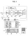
- FIG. 1is a block diagram of a color picture display apparatus embodying the present invention
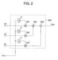
- FIG. 2is a more detailed block diagram showing part of the color converter in FIG. 1;
- FIG. 3is a more detailed block diagram showing the circuits for driving one light-emitting element in FIG. 1;
- FIG. 4is a waveform diagram illustrating the driving of a light-emitting element
- FIG. 5shows a variation of the circuits in FIG. 3
- FIG. 6illustrates a projection of a three-dimensional color coordinate system onto a two-dimensional chromaticity diagram
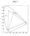
- FIG. 7illustrates the colors reproducible by LED and CRT display apparatus
- FIG. 8illustrates the ranges of variation of the primary colors in LED and CRT display apparatus
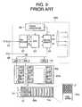
- FIG. 9is a block diagram of a color picture display apparatus illustrating the prior art.
- FIGS. 10A, 10 B, and 10 Cillustrate variations of the pixel arrangement in FIG. 1;
- FIGS. 11A, 11 B, and 11 Cillustrate driving circuits for the above variations.
- the embodimentis a color picture display apparatus comprising signal-processing circuitry 20 and a screen 21 .
- the screen 21comprises an m-by-n array of display units 30 , where m and n are positive integers that depend on the size of the screen.
- the display units 30are linked by data transmission lines 31 .
- Each display unit 30comprises a display control circuit 5 , a power supply 10 , and a plurality of pixel arrays 15 .
- Each pixel array 15has a matrix of red (R), green (G), and blue (B) LEDs arranged in a regular pattern, with twice as many red LEDs as green or blue LEDs. This arrangement will be referred to below as an RRGB arrangement.
- Each LEDfunctions as a separate pixel 2 in the pixel array 15 .
- the signal-processing circuitry 20comprises an input terminal 51 receiving an analog color television signal, an RGB decoder 52 that decodes the television signal to obtain red (R), green (G), and blue (B) monochromatic signals, and an analog-to-digital converter (ADC) 53 that samples the monochromatic signals and converts them to digital signals, referred to below as picture data.
- the sampling ratedepends on the number of pixels 2 on the screen 21 . Each sample is converted to a certain number of bits, which are stored temporarily in a picture memory 54 .
- the ADC 53 and picture memory 54operate according to timing signals supplied by a timing generator 55 .
- the timing generator 55supplies the ADC 53 with separate sampling timing signals for each of the three monochromatic signals R, G, and B.
- the sampling timing of each signalis matched to the positions of the corresponding pixels 2 in the display unit 30 , so that in one horizontal line, the R and G signals are sampled alternately, while in the next line, the B and R signals are sampled alternately.
- the picture data Rd, Gd, Bdare read from the picture memory 54 by a novel color converter 50 , which converts the picture data to modified picture data Rdm, Gdm, Bdm.
- the modified picture dataare transferred over a picture data bus 56 to a plurality of buffer memories 57 , together with a clock signal and other timing signals supplied by the timing generator 55 .
- the number of buffer memoriesis equal to the number (m) of columns of display units 30 ; in the drawing, the buffer memories are identified as BM 1 to BMm.
- the signal-processing circuitry 20also has a computer interface (I/F) 58 , through which picture data can be written into the picture memory 54 , and coefficient data can be written into the color converter 50 .
- I/Fcomputer interface
- Each buffer memory 57supplies modified picture data to one column of display units 30 via one data transmission line 31 .
- the data transfer rate on each data transmission line 31is lower than the data transfer rate on the picture data bus 56 ; the function of the buffer memory 57 is to convert between the two rates.
- the data transmission lines 31also carry timing signals.
- the display control circuits 5 in the display units 30use the timing signals to convert the modified picture data to driving signals that drive the pixel arrays 15 .
- the pixels 2emit light, forming a single picture that covers the entire screen 21 . Each pixel is driven according to the red, green, or blue sample value at the corresponding point in the picture received at the input terminal 51 or computer interface terminal 58 .
- FIG. 2illustrates the internal structure of the color converter 50 , showing the circuits 500 that generate the modified red data Rdm.
- These circuits 500include three registers ra, rb, rc that output coefficients a, b, c, respectively, a multiplier 501 that multiplies the red data Rd by coefficient a, a multiplier 502 that multiplies the green data Gd by coefficient b, a multiplier 503 that multiplies the blue data Bd by coefficient c, and adders 504 , 505 that sum the outputs of the three multipliers 501 , 502 , 503 to obtain the modified red data Rdm.
- the coefficients a, b, care written into registers ra, rb, rc through the computer interface 58 .
- the circuits that generate the modified green data Gdm and modified blue data Bdmhave similar configurations, with different coefficients (d, e, f, g, h, i).
- FIG. 3shows the circuits for driving one pixel 2 .
- the pixel value Dgis latched in a multiple-bit latch 4 at regular intervals specified by a latch signal LA.
- the pixel dataare six-bit data; MSB indicates the most significant bit, and LSB the least significant bit.
- a counter 3counts pulses of a clock signal CKO, making one complete counting cycle per field of the displayed picture.
- the counter 3is a six-bit counter, and the clock frequency is sixty-four (2 6 ) times the field frequency.
- the latch signal LA and clock signal CKOare timing signals supplied from the data transmission line 31 .
- a comparator 1compares the counter output Dr with the pixel value Dg, generating an output signal that is active when Dg exceeds Dr (Dg>Dr), and inactive when Dg does not exceed Dr (Dg ⁇ Dr).
- a driver 60which was omitted in FIG. 1, supplies driving current to the pixel 2 when the output signal from the comparator 1 is active.
- FIG. 4illustrates the driving of a pixel 2 by showing a waveform of the output of the comparator 1 during one field.
- the symbol Tgrepresents the CKO clock period. If the pixel value Dg is a positive integer R, the comparator output is active (high) for the first R clock periods of the field, having a duration ⁇ . As long as Dg remains unchanged, this waveform is repeated in every field.
- the driving schemeis thus a pulse-width modulation (PWM) scheme providing sixty-four brightness levels.
- PWMpulse-width modulation
- FIG. 5shows a variation of the display control circuit 5 a in which the pixel values Dg of all driven pixels are stored in a memory 40 .
- a separate memory 40is provided for each display unit 30 .
- the entire contents of the memory 40are compared with the single count value Dr output by the counter 3 , and the results Dp are shifted into a shift register 44 .
- the contents of the shift register 44are latched in a parallel set of latches 45 , for output to the drivers 60 during the next CKO clock cycle.
- Read addresses ADDRare generated by an address counter 46 and supplied to the memory 40 .
- the address counter 46counts cycles of a clock signal CKP having a frequency P times higher than the CKO frequency, where P is the number of pixels 2 driven by the display control circuit 5 a.
- the address counter 46is a modulo-P counter; a pulse of the clock signal CKO is generated each time the address returns from (P ⁇ 1) to zero. Because this display control circuit 5 a uses the same comparator 1 for all P pixels, it requires less circuitry than the display control circuit 5 in FIG. 3 .
- an external computing device(not shown) writes or programs coefficient values (a to i) in the registers of the color converter 50 .
- the coefficientstransform picture data Rd, Gd, Bd suitable for reproduction on a CRT screen to modified picture data Rdm, Gdm, Bdm that reproduce substantially the same colors with LEDs.
- the transformationcan be illustrated geometrically as follows.
- FIG. 6shows a color coordinate system defined by vectors X, Y, Z as in the CIE standard observer system.
- CIEstands for the International Commission on Illumination, or Commission Internationale de l'Eclairage.
- Vectors R, G, and Bindicate the colors of light emitted by the red, green, and blue LEDs employed in the screen 21 .
- the hatched trianglerepresents the gamut of reproducible colors in the plane defined by the equation
- the curve surrounding this triangle in the same planeis the spectrum locus. Different points on this locus indicate different hues.
- the spectrum locus and the gamut of reproducible colorscan be projected onto the X-Y plane as indicated by the vertical arrows in FIG. 6 to obtain the chromaticity diagram shown in FIG. 7 .
- the chromaticity coordinatesare conventionally denoted by lower-case letters x and y.
- the triangles labeled LED and CRTillustrate the gamut of colors reproducible on an LED display screen, and the gamut of colors reproducible on a CRT display screen.
- the coefficients written in the color converter 50effect the transformation indicated by the arrows in FIG. 7, so that colors are rendered on the LED screen 20 exactly as they would be on a CRT screen.
- this transformationis not quite feasible, because the colors generated by the red, green, and blue phosphors on CRT screens lie slightly outside the gamut of colors reproducible on an LED screen.
- the red, green, and blue primariesare therefore transformed from the vertices of the LED triangle to points that lie within both the LED and CRT triangles. Pure green is rendered as a mixture of green and red. Pure red is rendered as red with a slight admixture of green. Pure blue is rendered as blue with a slight admixture of red.
- this transformationcauses substantially the same hues to be reproduced on the LED screen 21 as would be reproduced on a CRT screen.
- a further consequenceis that the red LEDs are driven when any color is reproduced, other than black.
- the modified picture dataare supplied through the buffer memories 57 to the display control circuits 5 in the display units 30 , and the picture is displayed on the screen 21 . Since the sampling of the R, G, and B analog signals in the signal-processing circuitry 20 matches the separate positions of the red, green, and blue pixels on the screen 21 , a comparatively high resolution is obtained. Moreover, since the red LEDs are driven even when the picture is purely green or blue, the grainy effect caused by the comparatively wide separation of the green and blue pixels 2 is avoided.
- the transformation performed by the color converter 50adds enough red light to fill in the spaces between the green pixels, avoiding the appearance of discrete green dots.
- the human visual systemintegrates the red and green light to perceive a shade of green similar to that perceived on a CRT screen.
- the spaces between the blue pixels in a blue picture areaare filled in with a certain amount of red light
- the spaces between the red pixels in a red picture areaare filled in with a certain amount of green light, avoiding graininess in both cases.
- the coefficient values (a to i) written into the color converter 50can be selected to optimize the overall quality of the picture, balancing the factors of graininess, resolution, and accurate color rendition.
- the coefficientscan be chosen so that every color is rendered as a mixture of all three primary colors. Then all pixels are always driven, and no black gaps are left in the picture, except when black is displayed intentionally. Although the displayed colors are altered somewhat, a striking improvement in picture quality can be obtained in this way.
- the coefficient valuescan also be selected to compensate for ambient lighting conditions. If desired, the coefficients can furthermore be altered when computer-generated graphics, supplied through the computer interface 58 , are displayed instead of a television picture. A wide variety of effects can be achieved.
- FIG. 8shows the spectral variability of LEDs and CRT phosphors on a chromaticity diagram. Although the variability of all three types of LEDs is greater than the variability of the corresponding CRT phosphors, the variability of green LEDs is particularly large, and red LEDs have the least variability. The increased number of red LEDs in the RRGB pixel arrangement thus has the effect of improving the uniformity of color rendition.
- FIG. 9shows a block diagram of a color picture display apparatus lacking the color converter 50 and having an RGGB pixel arrangement, as found in the prior art.
- the same reference numeralsare used as in FIG. 1, with a suffix ‘a’ added to designate differing elements.
- the screen 21 a and display units 30 ahave the structure described above, except for the RGGB arrangement in the pixel arrays 15 a.
- the signal-processing circuitry 20 ahas the structure described above, except that the data read from the picture memory 54 are supplied directly to the buffer memories 57 .
- the large number of green pixelsexaggerates the picture degradation caused by the spectral variability of the green LEDs. Red and blue picture areas are also degraded by graininess, due to the wide separation between blue and red pixels, so substantially all picture areas are degraded in one way or another.
- FIGS. 10A, 10 B, and 10 Cshow examples of pixel arrays in which each pixel 2 comprises three, four, and five LEDs, respectively. Each pixel 2 comprises at least one LED of each of the three primary colors, and can generate any color obtainable by a combination of the three primaries.
- FIGS. 11A, 11 B, and 11 Cshow examples of circuits for driving these pixels. In these examples, the R, G, and B signals are sampled at the same timings in the signal-processing circuitry 20 , so a larger number of LEDs is required to achieve a given resolution.
- each pixelhas two green LEDs, but both green LEDs are driven according to the same modified value Gdm, so the variability of the two green LEDs tends to average out, reducing the perceived variation. This differs from the prior art in FIG. 9, in which each green LED is driven individually.
- the inventionhas been described in relation to a screen 21 employing LEDs, but the invention can be practiced with other types of light-emitting elements.
- the same signal-processing circuitry 20can be used with any type of screen, because the color converter 50 can be externally programmed with coefficients that compensate for the spectral characteristics of any type of light-emitting elements.
- the color converter 50is still useful in compensating for ambient conditions and achieving special effects.
- the coefficientscan be stored permanently in the color converter 50 , instead of being externally programmed through the computer interface 58 .
- the RRGB pattern shown in FIG. 1can be modified to another pattern in which less variable, longer-wavelength light-emitting elements are more numerous than more-variable, shorter-wavelength light-emitting elements.
- the inventionprovides a color picture display apparatus with highly flexible signal-processing circuitry, capable of good color rendition under any conditions, with a screen having any type of light-emitting elements.
- the inventionimproves the perceived picture quality by rendering all colors as combinations of light from light-emitting elements of at least two different colors, thereby reducing picture noise and avoiding a grainy appearance.
- the inventionfurther improves the perceived picture quality by employing a larger number of longer-wavelength LEDs, specifically red LEDs, which are less variable in their spectral characteristics than shorter-wavelength LEDs, and thus provide more accurate color rendition.
Landscapes
- Engineering & Computer Science (AREA)
- Multimedia (AREA)
- Signal Processing (AREA)
- Physics & Mathematics (AREA)
- Computer Hardware Design (AREA)
- General Physics & Mathematics (AREA)
- Theoretical Computer Science (AREA)
- Video Image Reproduction Devices For Color Tv Systems (AREA)
- Processing Of Color Television Signals (AREA)
- Control Of Indicators Other Than Cathode Ray Tubes (AREA)
Abstract
Description

Claims (16)
Applications Claiming Priority (2)
| Application Number | Priority Date | Filing Date | Title |
|---|---|---|---|
| JP08326699AJP3702699B2 (en) | 1999-03-26 | 1999-03-26 | Color image display device |
| JP11-083266 | 1999-03-26 |
Publications (1)
| Publication Number | Publication Date |
|---|---|
| US6486923B1true US6486923B1 (en) | 2002-11-26 |
Family
ID=13797562
Family Applications (1)
| Application Number | Title | Priority Date | Filing Date |
|---|---|---|---|
| US09/477,364Expired - LifetimeUS6486923B1 (en) | 1999-03-26 | 2000-01-04 | Color picture display apparatus using hue modification to improve picture quality |
Country Status (2)
| Country | Link |
|---|---|
| US (1) | US6486923B1 (en) |
| JP (1) | JP3702699B2 (en) |
Cited By (38)
| Publication number | Priority date | Publication date | Assignee | Title |
|---|---|---|---|---|
| US20030016198A1 (en)* | 2000-02-03 | 2003-01-23 | Yoshifumi Nagai | Image display and control method thereof |
| US20030043088A1 (en)* | 2001-08-31 | 2003-03-06 | Booth Lawrence A. | Compensating organic light emitting device displays for color variations |
| US20030090581A1 (en)* | 2000-07-28 | 2003-05-15 | Credelle Thomas Lloyd | Color display having horizontal sub-pixel arrangements and layouts |
| US20030128179A1 (en)* | 2002-01-07 | 2003-07-10 | Credelle Thomas Lloyd | Color flat panel display sub-pixel arrangements and layouts for sub-pixel rendering with split blue sub-pixels |
| US6639574B2 (en)* | 2002-01-09 | 2003-10-28 | Landmark Screens Llc | Light-emitting diode display |
| US20040218759A1 (en)* | 1999-10-20 | 2004-11-04 | Microsoft Corporation | Methods and apparatus for protecting information content |
| US20040263528A1 (en)* | 2003-06-26 | 2004-12-30 | Murdoch Michael J. | Method for transforming three color input signals to four or more output signals for a color display |
| US20050134168A1 (en)* | 2003-11-29 | 2005-06-23 | Su-Kyung Lee | Electron emission device and method of manufacturing the same |
| EP1548695A1 (en)* | 2003-12-23 | 2005-06-29 | Barco N.V. | Colour calibration of emissive display devices |
| EP1550994A1 (en)* | 2003-12-23 | 2005-07-06 | Barco N.V. | Colour calibration of emissive display devices |
| US20050169007A1 (en)* | 2004-02-02 | 2005-08-04 | Shen-Hong Chou | Backlight unit and liquid crystal display utilizing the same |
| US20050174309A1 (en)* | 2003-12-23 | 2005-08-11 | Luc Bouwens | Colour calibration of emissive display devices |
| US20050174363A1 (en)* | 2000-07-28 | 2005-08-11 | Clairvoyante, Inc. | Arrangements of color pixels for full color imaging devices with simplified addressing |
| US20050207577A1 (en)* | 1999-10-20 | 2005-09-22 | Microsoft Corporation | Methods and apparatus for protecting signals transmitted between a source and destination device over multiple signal lines |
| US6950115B2 (en) | 2001-05-09 | 2005-09-27 | Clairvoyante, Inc. | Color flat panel display sub-pixel arrangements and layouts |
| US20050248262A1 (en)* | 2000-07-28 | 2005-11-10 | Clairvoyante, Inc | Arrangement of color pixels for full color imaging devices with simplified addressing |
| US7084923B2 (en) | 2003-10-28 | 2006-08-01 | Clairvoyante, Inc | Display system having improved multiple modes for displaying image data from multiple input source formats |
| US20070109331A1 (en)* | 2001-05-09 | 2007-05-17 | Clairvoyante, Inc | Conversion of a sub-pixel format data to another sub-pixel data format |
| US7248268B2 (en) | 2004-04-09 | 2007-07-24 | Clairvoyante, Inc | Subpixel rendering filters for high brightness subpixel layouts |
| US20070176942A1 (en)* | 2006-01-31 | 2007-08-02 | Canon Kabushiki Kaisha | Color difference display control apparatus, color difference display control method, and control program |
| US20070177237A1 (en)* | 2006-01-31 | 2007-08-02 | Canon Kabushiki Kaisha | Display apparatus, display method, and control program |
| US7268758B2 (en) | 2004-03-23 | 2007-09-11 | Clairvoyante, Inc | Transistor backplanes for liquid crystal displays comprising different sized subpixels |
| US20070257946A1 (en)* | 2006-05-08 | 2007-11-08 | Eastman Kodak Company | Color display system with improved apparent resolution |
| US7492379B2 (en) | 2002-01-07 | 2009-02-17 | Samsung Electronics Co., Ltd. | Color flat panel display sub-pixel arrangements and layouts for sub-pixel rendering with increased modulation transfer function response |
| US7525526B2 (en) | 2003-10-28 | 2009-04-28 | Samsung Electronics Co., Ltd. | System and method for performing image reconstruction and subpixel rendering to effect scaling for multi-mode display |
| US20090213036A1 (en)* | 2008-02-25 | 2009-08-27 | Mitsubishi Electric Corporation | Image display device and display unit for image display device |
| US20090278982A1 (en)* | 2006-05-15 | 2009-11-12 | Takumi Imai | Color image display device and color conversion device |
| US20100020115A1 (en)* | 2008-07-24 | 2010-01-28 | Seiko Epson Corporation | Image display control device, image display control program, and image display control method |
| US20100141693A1 (en)* | 2007-04-24 | 2010-06-10 | Tae-Joong Lee | Organic light-emitting display apparatus and method for driving the same |
| US7755652B2 (en) | 2002-01-07 | 2010-07-13 | Samsung Electronics Co., Ltd. | Color flat panel display sub-pixel rendering and driver configuration for sub-pixel arrangements with split sub-pixels |
| US7876341B2 (en) | 2006-08-28 | 2011-01-25 | Samsung Electronics Co., Ltd. | Subpixel layouts for high brightness displays and systems |
| CN101105902B (en)* | 2006-07-12 | 2011-08-10 | 深圳市健隆新光电技术有限公司 | High brightness, high resolution ratio LED display screen and its drive method |
| US8018476B2 (en) | 2006-08-28 | 2011-09-13 | Samsung Electronics Co., Ltd. | Subpixel layouts for high brightness displays and systems |
| CN103379702A (en)* | 2012-04-27 | 2013-10-30 | 宣昶股份有限公司 | Light emitting diode driving circuit, light emitting diode driving device and driving method |
| US20130285570A1 (en)* | 2012-04-27 | 2013-10-31 | Chi-Jen KUO | Led driving circuit, led driving device and driving method |
| CN104091538A (en)* | 2014-07-10 | 2014-10-08 | 福建华瀚明光电科技有限公司 | LED dot matrix module and production technology thereof |
| US9886932B2 (en)* | 2012-09-07 | 2018-02-06 | Sharp Kabushiki Kaisha | Multi-primary color display device |
| US12283222B2 (en)* | 2022-06-13 | 2025-04-22 | Samsung Display Co., Ltd. | Driving controller and display device including the same |
Families Citing this family (1)
| Publication number | Priority date | Publication date | Assignee | Title |
|---|---|---|---|---|
| JPWO2013099560A1 (en) | 2011-12-27 | 2015-04-30 | 三菱電機株式会社 | Display device |
Citations (20)
| Publication number | Priority date | Publication date | Assignee | Title |
|---|---|---|---|---|
| JPS4887975A (en) | 1972-02-22 | 1973-11-19 | ||
| JPS5074932A (en) | 1973-11-02 | 1975-06-19 | ||
| US4298868A (en)* | 1980-04-11 | 1981-11-03 | Spurgeon John R | Electronic display apparatus |
| US4445132A (en)* | 1980-06-13 | 1984-04-24 | Tokyo Shibaura Denki Kabushiki Kaisha | LED Module for a flat panel display unit |
| US4679072A (en)* | 1984-12-20 | 1987-07-07 | Canon Kabushiki Kaisha | Color adjusting device |
| US4694330A (en)* | 1984-08-21 | 1987-09-15 | Sony Corporation | Color correction circuit |
| US5121476A (en)* | 1988-02-22 | 1992-06-09 | Yee Keen Y | TV data capture device |
| US5235413A (en)* | 1991-07-26 | 1993-08-10 | Tektronix, Inc. | Method and apparatus for processing component signals to preserve high frequency intensity information |
| US5258829A (en)* | 1991-03-19 | 1993-11-02 | Sony Corporation | Color display apparatus for use with input signals having different color reproduction characteristics |
| JPH06111736A (en) | 1992-09-25 | 1994-04-22 | Ise Electronics Corp | Light emitting element |
| US5452093A (en)* | 1991-05-27 | 1995-09-19 | Samsung Electronics Co., Ltd. | High speed color video printer for printing color image data in successive columns during blanking intervals of a video roster scan |
| US5461429A (en)* | 1992-09-02 | 1995-10-24 | Matsushita Electric Industrial Co., Ltd. | White balance and image color control device |
| JPH08317414A (en) | 1995-05-18 | 1996-11-29 | Toshiba Corp | LED display device |
| US5677741A (en)* | 1994-04-27 | 1997-10-14 | Canon Kabushiki Kaisha | Image processing apparatus and method capable of adjusting hues of video signals in conversion to display signals |
| JPH1132347A (en) | 1997-07-08 | 1999-02-02 | Pioneer Electron Corp | Display device |
| US6025885A (en)* | 1995-02-24 | 2000-02-15 | Ldt-Gmbh & Co. Laser-Display-Technologie Kg | Process for color transformation and a color video system |
| US6144352A (en)* | 1997-05-15 | 2000-11-07 | Matsushita Electric Industrial Co., Ltd. | LED display device and method for controlling the same |
| US6211917B1 (en)* | 1997-06-10 | 2001-04-03 | Rong-Fuh Shyu | Method for performing plural matrix multiplication operations using a shared look-up table |
| US6297851B1 (en)* | 1997-07-17 | 2001-10-02 | Hewlett-Packard Co | Analog video frame capture and preview |
| US6369860B1 (en)* | 1995-01-18 | 2002-04-09 | Sony Corporation | Color conversion apparatus and method for image data |
- 1999
- 1999-03-26JPJP08326699Apatent/JP3702699B2/ennot_activeExpired - Lifetime
- 2000
- 2000-01-04USUS09/477,364patent/US6486923B1/ennot_activeExpired - Lifetime
Patent Citations (20)
| Publication number | Priority date | Publication date | Assignee | Title |
|---|---|---|---|---|
| JPS4887975A (en) | 1972-02-22 | 1973-11-19 | ||
| JPS5074932A (en) | 1973-11-02 | 1975-06-19 | ||
| US4298868A (en)* | 1980-04-11 | 1981-11-03 | Spurgeon John R | Electronic display apparatus |
| US4445132A (en)* | 1980-06-13 | 1984-04-24 | Tokyo Shibaura Denki Kabushiki Kaisha | LED Module for a flat panel display unit |
| US4694330A (en)* | 1984-08-21 | 1987-09-15 | Sony Corporation | Color correction circuit |
| US4679072A (en)* | 1984-12-20 | 1987-07-07 | Canon Kabushiki Kaisha | Color adjusting device |
| US5121476A (en)* | 1988-02-22 | 1992-06-09 | Yee Keen Y | TV data capture device |
| US5258829A (en)* | 1991-03-19 | 1993-11-02 | Sony Corporation | Color display apparatus for use with input signals having different color reproduction characteristics |
| US5452093A (en)* | 1991-05-27 | 1995-09-19 | Samsung Electronics Co., Ltd. | High speed color video printer for printing color image data in successive columns during blanking intervals of a video roster scan |
| US5235413A (en)* | 1991-07-26 | 1993-08-10 | Tektronix, Inc. | Method and apparatus for processing component signals to preserve high frequency intensity information |
| US5461429A (en)* | 1992-09-02 | 1995-10-24 | Matsushita Electric Industrial Co., Ltd. | White balance and image color control device |
| JPH06111736A (en) | 1992-09-25 | 1994-04-22 | Ise Electronics Corp | Light emitting element |
| US5677741A (en)* | 1994-04-27 | 1997-10-14 | Canon Kabushiki Kaisha | Image processing apparatus and method capable of adjusting hues of video signals in conversion to display signals |
| US6369860B1 (en)* | 1995-01-18 | 2002-04-09 | Sony Corporation | Color conversion apparatus and method for image data |
| US6025885A (en)* | 1995-02-24 | 2000-02-15 | Ldt-Gmbh & Co. Laser-Display-Technologie Kg | Process for color transformation and a color video system |
| JPH08317414A (en) | 1995-05-18 | 1996-11-29 | Toshiba Corp | LED display device |
| US6144352A (en)* | 1997-05-15 | 2000-11-07 | Matsushita Electric Industrial Co., Ltd. | LED display device and method for controlling the same |
| US6211917B1 (en)* | 1997-06-10 | 2001-04-03 | Rong-Fuh Shyu | Method for performing plural matrix multiplication operations using a shared look-up table |
| JPH1132347A (en) | 1997-07-08 | 1999-02-02 | Pioneer Electron Corp | Display device |
| US6297851B1 (en)* | 1997-07-17 | 2001-10-02 | Hewlett-Packard Co | Analog video frame capture and preview |
Cited By (79)
| Publication number | Priority date | Publication date | Assignee | Title |
|---|---|---|---|---|
| US7580526B2 (en) | 1999-10-20 | 2009-08-25 | Microsoft Corporation | Methods and apparatus for protecting signals transmitted between a source and destination device over multiple signals lines |
| US7362861B2 (en)* | 1999-10-20 | 2008-04-22 | Microsoft Corporation | Methods and apparatus for protecting information content |
| US6996236B1 (en)* | 1999-10-20 | 2006-02-07 | Microsoft Corporation | Methods and apparatus for protecting signals transmitted between a source and destination device over multiple signal lines |
| US6983050B1 (en)* | 1999-10-20 | 2006-01-03 | Microsoft Corporation | Methods and apparatus for protecting information content |
| US20040218759A1 (en)* | 1999-10-20 | 2004-11-04 | Microsoft Corporation | Methods and apparatus for protecting information content |
| US20050207577A1 (en)* | 1999-10-20 | 2005-09-22 | Microsoft Corporation | Methods and apparatus for protecting signals transmitted between a source and destination device over multiple signal lines |
| US20050195976A1 (en)* | 1999-10-20 | 2005-09-08 | Microsoft Corporation | System for protecting information content |
| US20030016198A1 (en)* | 2000-02-03 | 2003-01-23 | Yoshifumi Nagai | Image display and control method thereof |
| US20040046720A1 (en)* | 2000-02-03 | 2004-03-11 | Yoshifumi Nagai | Image display apparatus and control method thereof |
| US20050174363A1 (en)* | 2000-07-28 | 2005-08-11 | Clairvoyante, Inc. | Arrangements of color pixels for full color imaging devices with simplified addressing |
| US20050248262A1 (en)* | 2000-07-28 | 2005-11-10 | Clairvoyante, Inc | Arrangement of color pixels for full color imaging devices with simplified addressing |
| US7646398B2 (en)* | 2000-07-28 | 2010-01-12 | Samsung Electronics Co., Ltd. | Arrangement of color pixels for full color imaging devices with simplified addressing |
| US7283142B2 (en)* | 2000-07-28 | 2007-10-16 | Clairvoyante, Inc. | Color display having horizontal sub-pixel arrangements and layouts |
| US7728802B2 (en)* | 2000-07-28 | 2010-06-01 | Samsung Electronics Co., Ltd. | Arrangements of color pixels for full color imaging devices with simplified addressing |
| US7274383B1 (en)* | 2000-07-28 | 2007-09-25 | Clairvoyante, Inc | Arrangement of color pixels for full color imaging devices with simplified addressing |
| US20030090581A1 (en)* | 2000-07-28 | 2003-05-15 | Credelle Thomas Lloyd | Color display having horizontal sub-pixel arrangements and layouts |
| US7889215B2 (en) | 2001-05-09 | 2011-02-15 | Samsung Electronics Co., Ltd. | Conversion of a sub-pixel format data to another sub-pixel data format |
| US6950115B2 (en) | 2001-05-09 | 2005-09-27 | Clairvoyante, Inc. | Color flat panel display sub-pixel arrangements and layouts |
| US7688335B2 (en) | 2001-05-09 | 2010-03-30 | Samsung Electronics Co., Ltd. | Conversion of a sub-pixel format data to another sub-pixel data format |
| US20050264588A1 (en)* | 2001-05-09 | 2005-12-01 | Clairvoyante, Inc | Color flat panel display sub-pixel arrangements and layouts |
| US7916156B2 (en) | 2001-05-09 | 2011-03-29 | Samsung Electronics Co., Ltd. | Conversion of a sub-pixel format data to another sub-pixel data format |
| US8223168B2 (en) | 2001-05-09 | 2012-07-17 | Samsung Electronics Co., Ltd. | Conversion of a sub-pixel format data |
| US7755648B2 (en) | 2001-05-09 | 2010-07-13 | Samsung Electronics Co., Ltd. | Color flat panel display sub-pixel arrangements and layouts |
| US20070109331A1 (en)* | 2001-05-09 | 2007-05-17 | Clairvoyante, Inc | Conversion of a sub-pixel format data to another sub-pixel data format |
| US20070109330A1 (en)* | 2001-05-09 | 2007-05-17 | Clairvoyante, Inc | Conversion of a sub-pixel format data to another sub-pixel data format |
| US7598963B2 (en) | 2001-05-09 | 2009-10-06 | Samsung Electronics Co., Ltd. | Operating sub-pixel rendering filters in a display system |
| US7027015B2 (en)* | 2001-08-31 | 2006-04-11 | Intel Corporation | Compensating organic light emitting device displays for color variations |
| US20030043088A1 (en)* | 2001-08-31 | 2003-03-06 | Booth Lawrence A. | Compensating organic light emitting device displays for color variations |
| US7492379B2 (en) | 2002-01-07 | 2009-02-17 | Samsung Electronics Co., Ltd. | Color flat panel display sub-pixel arrangements and layouts for sub-pixel rendering with increased modulation transfer function response |
| US7417648B2 (en) | 2002-01-07 | 2008-08-26 | Samsung Electronics Co. Ltd., | Color flat panel display sub-pixel arrangements and layouts for sub-pixel rendering with split blue sub-pixels |
| US7755652B2 (en) | 2002-01-07 | 2010-07-13 | Samsung Electronics Co., Ltd. | Color flat panel display sub-pixel rendering and driver configuration for sub-pixel arrangements with split sub-pixels |
| US8456496B2 (en) | 2002-01-07 | 2013-06-04 | Samsung Display Co., Ltd. | Color flat panel display sub-pixel arrangements and layouts for sub-pixel rendering with split blue sub-pixels |
| US20030128179A1 (en)* | 2002-01-07 | 2003-07-10 | Credelle Thomas Lloyd | Color flat panel display sub-pixel arrangements and layouts for sub-pixel rendering with split blue sub-pixels |
| US8134583B2 (en) | 2002-01-07 | 2012-03-13 | Samsung Electronics Co., Ltd. | To color flat panel display sub-pixel arrangements and layouts for sub-pixel rendering with split blue sub-pixels |
| US6639574B2 (en)* | 2002-01-09 | 2003-10-28 | Landmark Screens Llc | Light-emitting diode display |
| USRE40953E1 (en)* | 2002-01-09 | 2009-11-10 | Landmark Screens, Llc | Light-emitting diode display |
| US20040263528A1 (en)* | 2003-06-26 | 2004-12-30 | Murdoch Michael J. | Method for transforming three color input signals to four or more output signals for a color display |
| US6897876B2 (en)* | 2003-06-26 | 2005-05-24 | Eastman Kodak Company | Method for transforming three color input signals to four or more output signals for a color display |
| US7084923B2 (en) | 2003-10-28 | 2006-08-01 | Clairvoyante, Inc | Display system having improved multiple modes for displaying image data from multiple input source formats |
| US7525526B2 (en) | 2003-10-28 | 2009-04-28 | Samsung Electronics Co., Ltd. | System and method for performing image reconstruction and subpixel rendering to effect scaling for multi-mode display |
| US7646430B2 (en) | 2003-10-28 | 2010-01-12 | Samsung Electronics Co., Ltd. | Display system having improved multiple modes for displaying image data from multiple input source formats |
| US20050134168A1 (en)* | 2003-11-29 | 2005-06-23 | Su-Kyung Lee | Electron emission device and method of manufacturing the same |
| US7642705B2 (en)* | 2003-11-29 | 2010-01-05 | Samsung Sdi Co., Ltd. | Electron emission device and method of manufacturing the same |
| EP1550994A1 (en)* | 2003-12-23 | 2005-07-06 | Barco N.V. | Colour calibration of emissive display devices |
| US20050174309A1 (en)* | 2003-12-23 | 2005-08-11 | Luc Bouwens | Colour calibration of emissive display devices |
| EP1548695A1 (en)* | 2003-12-23 | 2005-06-29 | Barco N.V. | Colour calibration of emissive display devices |
| US7365720B2 (en) | 2003-12-23 | 2008-04-29 | Barco N.V. | Colour calibration of emissive display devices |
| US7270461B2 (en)* | 2004-02-02 | 2007-09-18 | Au Optronics Corp. | Backlight unit and liquid crystal display utilizing the same |
| US20050169007A1 (en)* | 2004-02-02 | 2005-08-04 | Shen-Hong Chou | Backlight unit and liquid crystal display utilizing the same |
| US7268758B2 (en) | 2004-03-23 | 2007-09-11 | Clairvoyante, Inc | Transistor backplanes for liquid crystal displays comprising different sized subpixels |
| US7598965B2 (en) | 2004-04-09 | 2009-10-06 | Samsung Electronics Co., Ltd. | Subpixel rendering filters for high brightness subpixel layouts |
| US8390646B2 (en) | 2004-04-09 | 2013-03-05 | Samsung Display Co., Ltd. | Subpixel rendering filters for high brightness subpixel layouts |
| US7248268B2 (en) | 2004-04-09 | 2007-07-24 | Clairvoyante, Inc | Subpixel rendering filters for high brightness subpixel layouts |
| US7920154B2 (en) | 2004-04-09 | 2011-04-05 | Samsung Electronics Co., Ltd. | Subpixel rendering filters for high brightness subpixel layouts |
| US8064113B2 (en)* | 2006-01-31 | 2011-11-22 | Canon Kabushiki Kaisha | Display apparatus, display method, and control program |
| US20070177237A1 (en)* | 2006-01-31 | 2007-08-02 | Canon Kabushiki Kaisha | Display apparatus, display method, and control program |
| US20070176942A1 (en)* | 2006-01-31 | 2007-08-02 | Canon Kabushiki Kaisha | Color difference display control apparatus, color difference display control method, and control program |
| US8174536B2 (en) | 2006-01-31 | 2012-05-08 | Canon Kabushiki Kaisha | Color difference display control apparatus, color difference display control method, and control program |
| US7969428B2 (en)* | 2006-05-08 | 2011-06-28 | Global Oled Technology Llc | Color display system with improved apparent resolution |
| US20070257946A1 (en)* | 2006-05-08 | 2007-11-08 | Eastman Kodak Company | Color display system with improved apparent resolution |
| US8194095B2 (en) | 2006-05-15 | 2012-06-05 | Sharp Kabushiki Kaisha | Color image display device and color conversion device |
| US20090278982A1 (en)* | 2006-05-15 | 2009-11-12 | Takumi Imai | Color image display device and color conversion device |
| CN101105902B (en)* | 2006-07-12 | 2011-08-10 | 深圳市健隆新光电技术有限公司 | High brightness, high resolution ratio LED display screen and its drive method |
| US8018476B2 (en) | 2006-08-28 | 2011-09-13 | Samsung Electronics Co., Ltd. | Subpixel layouts for high brightness displays and systems |
| US7876341B2 (en) | 2006-08-28 | 2011-01-25 | Samsung Electronics Co., Ltd. | Subpixel layouts for high brightness displays and systems |
| US20100141693A1 (en)* | 2007-04-24 | 2010-06-10 | Tae-Joong Lee | Organic light-emitting display apparatus and method for driving the same |
| US8711066B2 (en)* | 2008-02-25 | 2014-04-29 | Mitsubishi Electric Corporation | Image display device and display unit for image display device |
| US20090213036A1 (en)* | 2008-02-25 | 2009-08-27 | Mitsubishi Electric Corporation | Image display device and display unit for image display device |
| US9599323B2 (en) | 2008-02-25 | 2017-03-21 | Mitsubishi Electric Corporation | Image display device and display unit for image display device |
| US20100020115A1 (en)* | 2008-07-24 | 2010-01-28 | Seiko Epson Corporation | Image display control device, image display control program, and image display control method |
| US8477160B2 (en)* | 2008-07-24 | 2013-07-02 | Seiko Epson Corporation | Image display control device, image display control program, and image display control method |
| CN103379702A (en)* | 2012-04-27 | 2013-10-30 | 宣昶股份有限公司 | Light emitting diode driving circuit, light emitting diode driving device and driving method |
| US9271360B2 (en)* | 2012-04-27 | 2016-02-23 | Maxtek Technology Co., Ltd. | LED driving circuit, LED driving device and driving method |
| US20130285570A1 (en)* | 2012-04-27 | 2013-10-31 | Chi-Jen KUO | Led driving circuit, led driving device and driving method |
| TWI581658B (en)* | 2012-04-27 | 2017-05-01 | 宣昶股份有限公司 | Light-emitting diode driving circuit, light-emitting diode driving device and driving method |
| US9886932B2 (en)* | 2012-09-07 | 2018-02-06 | Sharp Kabushiki Kaisha | Multi-primary color display device |
| CN104091538A (en)* | 2014-07-10 | 2014-10-08 | 福建华瀚明光电科技有限公司 | LED dot matrix module and production technology thereof |
| CN104091538B (en)* | 2014-07-10 | 2016-08-31 | 东莞市光劲光电有限公司 | A kind of LED dot array module and production technology thereof |
| US12283222B2 (en)* | 2022-06-13 | 2025-04-22 | Samsung Display Co., Ltd. | Driving controller and display device including the same |
Also Published As
| Publication number | Publication date |
|---|---|
| JP2000278705A (en) | 2000-10-06 |
| JP3702699B2 (en) | 2005-10-05 |
Similar Documents
| Publication | Publication Date | Title |
|---|---|---|
| US6486923B1 (en) | Color picture display apparatus using hue modification to improve picture quality | |
| US6734875B1 (en) | Fullcolor LED display system | |
| US7787055B2 (en) | Signal processing method, image display apparatus, and television apparatus | |
| KR100525602B1 (en) | Image display method and image display device | |
| CN101390150B (en) | System and method for improved subpixel rendering of image data in a non-stripe display system | |
| US7053868B1 (en) | Plasma display apparatus | |
| RU2249257C2 (en) | Method and device for representing data of multicolor image of bite-wise displaying on pixel matrix display screen, on which lamps of three main colors are positioned | |
| KR100312362B1 (en) | Method and apparatus for displaying moving images while correcting bad video contours | |
| US8411206B2 (en) | Apparatus and method for decoding extended color space data | |
| CN1159702A (en) | Projector based on DMD used for school | |
| KR100798309B1 (en) | Active Matrix Organic LED Driving Circuit | |
| JP3268001B2 (en) | LED dot matrix type display device | |
| US20020191008A1 (en) | Color image display apparatus and method | |
| KR20050111433A (en) | System for controlling light emitting diode module in electronic display board | |
| EP2009930A2 (en) | Image display apparatus | |
| US7158155B2 (en) | Subfield coding circuit and subfield coding method | |
| US5774178A (en) | Apparatus and method for rearranging digitized single-beam color video data and controlling output sequence and timing for multiple-beam color display | |
| US8531477B2 (en) | Devices and methods for providing an enhanced monochromatic display | |
| US20060044220A1 (en) | Circuit for driving a display panel | |
| JP3294597B2 (en) | Full color LED display system | |
| JPH05134624A (en) | Driving method for gas discharge display device | |
| JP2004514953A (en) | Subfield encoding apparatus and method | |
| JP2002215083A (en) | Display device and display brightness control method | |
| JPH0385687A (en) | Gradation display device |
Legal Events
| Date | Code | Title | Description |
|---|---|---|---|
| AS | Assignment | Owner name:MITSUBISHI DENKI KABUSHIKI KAISHA, JAPAN Free format text:ASSIGNMENT OF ASSIGNORS INTEREST;ASSIGNORS:MAESHIMA, KAZUYA;HARA, ZENICHIRO;OKAMOTO, TAKASHI;AND OTHERS;REEL/FRAME:010515/0352 Effective date:19991210 | |
| AS | Assignment | Owner name:MITSUBISHI DENKI KABUSHIKI KAISHA, JAPAN Free format text:ASSIGNMENT OF ASSIGNORS INTEREST;ASSIGNORS:MAESHIMA, KAZUYA;HARA, ZENICHIRO;OKAMOTO, TAKASHI;AND OTHERS;REEL/FRAME:010838/0083 Effective date:19991210 | |
| FEPP | Fee payment procedure | Free format text:PAYOR NUMBER ASSIGNED (ORIGINAL EVENT CODE: ASPN); ENTITY STATUS OF PATENT OWNER: LARGE ENTITY | |
| STCF | Information on status: patent grant | Free format text:PATENTED CASE | |
| FEPP | Fee payment procedure | Free format text:PAT HOLDER NO LONGER CLAIMS SMALL ENTITY STATUS, ENTITY STATUS SET TO UNDISCOUNTED (ORIGINAL EVENT CODE: STOL); ENTITY STATUS OF PATENT OWNER: LARGE ENTITY | |
| REFU | Refund | Free format text:REFUND - SURCHARGE, PETITION TO ACCEPT PYMT AFTER EXP, UNINTENTIONAL (ORIGINAL EVENT CODE: R2551); ENTITY STATUS OF PATENT OWNER: LARGE ENTITY | |
| FPAY | Fee payment | Year of fee payment:4 | |
| FPAY | Fee payment | Year of fee payment:8 | |
| FPAY | Fee payment | Year of fee payment:12 |