US6485506B2 - Normothermic treatment apparatus - Google Patents
Normothermic treatment apparatusDownload PDFInfo
- Publication number
- US6485506B2 US6485506B2US09/887,187US88718701AUS6485506B2US 6485506 B2US6485506 B2US 6485506B2US 88718701 AUS88718701 AUS 88718701AUS 6485506 B2US6485506 B2US 6485506B2
- Authority
- US
- United States
- Prior art keywords
- heater
- therapy
- temperature
- bandage
- controller
- Prior art date
- Legal status (The legal status is an assumption and is not a legal conclusion. Google has not performed a legal analysis and makes no representation as to the accuracy of the status listed.)
- Expired - Lifetime
Links
Images


Classifications
- A—HUMAN NECESSITIES
- A61—MEDICAL OR VETERINARY SCIENCE; HYGIENE
- A61F—FILTERS IMPLANTABLE INTO BLOOD VESSELS; PROSTHESES; DEVICES PROVIDING PATENCY TO, OR PREVENTING COLLAPSING OF, TUBULAR STRUCTURES OF THE BODY, e.g. STENTS; ORTHOPAEDIC, NURSING OR CONTRACEPTIVE DEVICES; FOMENTATION; TREATMENT OR PROTECTION OF EYES OR EARS; BANDAGES, DRESSINGS OR ABSORBENT PADS; FIRST-AID KITS
- A61F7/00—Heating or cooling appliances for medical or therapeutic treatment of the human body
- A61F7/007—Heating or cooling appliances for medical or therapeutic treatment of the human body characterised by electric heating
- A61F2007/0071—Heating or cooling appliances for medical or therapeutic treatment of the human body characterised by electric heating using a resistor, e.g. near the spot to be heated
- A—HUMAN NECESSITIES
- A61—MEDICAL OR VETERINARY SCIENCE; HYGIENE
- A61F—FILTERS IMPLANTABLE INTO BLOOD VESSELS; PROSTHESES; DEVICES PROVIDING PATENCY TO, OR PREVENTING COLLAPSING OF, TUBULAR STRUCTURES OF THE BODY, e.g. STENTS; ORTHOPAEDIC, NURSING OR CONTRACEPTIVE DEVICES; FOMENTATION; TREATMENT OR PROTECTION OF EYES OR EARS; BANDAGES, DRESSINGS OR ABSORBENT PADS; FIRST-AID KITS
- A61F7/00—Heating or cooling appliances for medical or therapeutic treatment of the human body
- A61F2007/0086—Heating or cooling appliances for medical or therapeutic treatment of the human body with a thermostat
- A—HUMAN NECESSITIES
- A61—MEDICAL OR VETERINARY SCIENCE; HYGIENE
- A61F—FILTERS IMPLANTABLE INTO BLOOD VESSELS; PROSTHESES; DEVICES PROVIDING PATENCY TO, OR PREVENTING COLLAPSING OF, TUBULAR STRUCTURES OF THE BODY, e.g. STENTS; ORTHOPAEDIC, NURSING OR CONTRACEPTIVE DEVICES; FOMENTATION; TREATMENT OR PROTECTION OF EYES OR EARS; BANDAGES, DRESSINGS OR ABSORBENT PADS; FIRST-AID KITS
- A61F7/00—Heating or cooling appliances for medical or therapeutic treatment of the human body
- A61F7/02—Compresses or poultices for effecting heating or cooling
- A61F2007/0295—Compresses or poultices for effecting heating or cooling for heating or cooling or use at more than one temperature
Definitions
- the present inventionrelates to a wound treatment device with a bandage and heater that are essentially planar, yet flexible, and are connected or joined by an attachment device that promotes heat transfer from the heater through the bandage to a wound treatment area where the temperature of tissue is maintained by control of the heater's operation in a normothermic temperature range.
- Woundsin general, are breaks in the integrity of the skin of a patient.
- a first type of woundmay result from mechanical trauma that produces a cut, tear, or an abrasion. There are many instruments of causality for such wounds, including knives, glass, gravel, or a scalpel.
- a second type of woundmay be caused by a combination of heat and pressure wherein the heat alone is insufficient to cause an outright burn. Such wounds include pressure sores, decubitus ulcers, or bed sores, and reflect an injury that is chronic in nature.
- a woundmay also be vascular in origin.
- blood flow through a regionmay be altered sufficiently to cause secondary weakening of tissues which are eventually disrupted, thus forming a wound.
- the primary difficultyis getting oxygenated blood to the affected area.
- the primary difficultyis fluid congestion in the affected area which backs up, decreasing the flow of oxygenated blood.
- these woundsmanifest underlying chronic disease processes, such as atherosclerotic vascular disease, congestive heart failure, and diabetes, these vascular injuries also are chronic in nature, forming wounds with ulcerated bases.
- Heat therapyhas been used to treat wounds since the days of Hippocrates, with varying results.
- heat therapy for woundshas involved the application of heat under conditions that make the tissues of a wound hyperthermic. Hyperthermia impedes wound healing and may actually damage the wound tissues.
- the “normal” range of temperature for the human bodyis 37° C. ⁇ 1° C. (36° C.-38° C.). This is termed the “normothermic” range. Humans exhibit a thermoregulatory response to core temperature changes as little as ⁇ 0.1° C., wherein “core” as used herein refers to interior portions of the body. This extremely tight temperature control is necessary because virtually all cellular functions, chemical reactions and enzymatic reactions are optimum at normothermia.
- the skin of the torsois usually hypothermic, while the skin of the legs is always hypothermic.
- the normal skin temperature of the distal legis approximately 32° C., which is considered to be “moderately hypothermic”.
- the skin temperature of the distal leg of a patient with vascular insufficiencymay be as low as 25° C., which is “severely hypothermic”.
- the hypothermic condition of wounds and ulcersinhibits healing.
- Severely hypothermic skin or wound tissueis in a state that may be termed “suspended animation”. In suspended animation, tissue is living, but cellular functions necessary for cell division and collagen deposition are slowed or even stopped.
- hypothermic liver transplant patientsrequired twice as many units of blood (18.6 vs.9.8) and 57% more units of all blood products (46.2vs. 29.4) than patients who were kept normothermic with the Bair Hugger® Patient Warming System.
- Warm water pads and bottles and electrical heating padsare cumbersome, reduce patient mobility, and are usually applied to the extremities and held in place with inconvenient wraps such as straps, hook-and-eye material or tabs.
- Whirlpools and Weg bathsreduce mobility and limit the duration of warming therapy due to skin maceration by the water. None of these modalities is capable of prolonged, uniform, normothermic heat treatment of a wound.
- This inventionis designed to elevate the temperature of hypothermic skin and subcutaneous tissue of a treatment area to a temperature which is close to normothermic.
- the inventionin operation, maintains the temperature of such tissue in a normothermic range of about 36° C. to 38° C.
- Still another objectis to provide a low profile, flexible wound treatment apparatus that includes a heater attached to a bandage and a controller connected to the heater for operating the heater so that the apparatus provides a normothermic therapy regime to a wound.
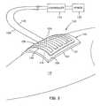
- FIG. 1is an isometric view of a first embodiment of the treatment apparatus being applied to a person's body.
- FIG. 2is an isometric view of the treatment apparatus applied to the person's body.
- FIG. 3is an exploded isometric view of the treatment apparatus
- FIG. 4is a cross-sectional view of the treatment apparatus applied to the person's body
- FIG. 5is an exploded cross-sectional illustration of an embodiment of the invention above a treatment area of the person's body
- FIG. 6is a view taken along plane VI—VI of FIG. 5;
- FIG. 7is a view taken along plane VII—VII of FIG. 5;
- FIG. 8is a view taken along plane VIII—VIII of FIG. 5;
- FIG. 9is a view taken along plane IX—IX of FIG. 5;
- FIG. 10is a view taken along plane X—X of FIG. 5;
- FIG. 11is a view taken along plane XI—XI of FIG. 5;
- FIG. 12is a view taken along plane XII—XII of FIG. 5;
- FIG. 13is an exploded cross-sectional view of the first embodiment of the treatment apparatus after attaching an attachment device to the heater;
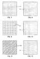
- FIG. 14Ais a planar illustration of an electrical resistance element embedded in a flexible layer for uniform heating
- FIG. 14Bis a view taken along plane XIVB—XIVB of FIG. 14A;
- FIG. 15Ais a planar view of an electrical resistance element embedded in a flexible layer for heating a portion of a treatment area
- FIG. 15Bis a view taken along plane XVB—XVB of FIG. 15A;
- FIG. 16Ais a planar view of an electrical resistance element embedded in a flexible layer for uniform heating of a central portion of a treatment area
- FIG. 16Bis a view taken along plane XVIB—XVIB of FIG. 16A;
- FIG. 17is an exploded cross-sectional view of another embodiment of the invention shown above a treatment area
- FIG. 18is a view taken along plane XVIII—XVIII of FIG. 17;
- FIG. 19is a view taken along plane XIX—XIX of FIG. 17;
- FIG. 20is a view taken along plane XX—XX of FIG. 17;
- FIG. 21is a view taken along plane XXI—XXI of FIG. 17;
- FIG. 22is a view taken along plane XXII—XXII of FIG. 17;
- FIG. 23is a view taken along plane XXIII—XXIII of FIG. 17;
- FIG. 24is a view taken along plane XXIV—XXIV of FIG. 17;
- FIG. 25is a view taken along plane XXV—XXV of FIG. 17;
- FIG. 26is a view taken along plane XXVI—XXVI of FIG. 17;
- FIG. 27is a view taken along plane XVII—XXVII of FIG. 17;
- FIG. 28is a view showing schematically the engagement of the intermittent adhesives shown in FIGS. 26 and 27;
- FIG. 29is an isometric illustration of a further embodiment of the treatment apparatus applied to a treatment area on the person's body;
- FIG. 30is an exploded cross-sectional illustration of the apparatus shown in FIG. 29 shown above the treatment area;
- FIG. 31is an exploded cross-sectional illustration of the FIG. 29 embodiment with an adhesive attachment device applied to the heater;
- FIG. 32is a block diagram that illustrates the present treatment apparatus for implementing normothermic heat therapy
- FIG. 33is a graph showing tissue and heater temperatures over a plurality of duty cycles
- FIG. 34is a temperature versus time graph showing tissue and heater temperature over a number of therapy cycles
- FIG. 35is a graph showing temperature versus time similar to the graph shown in FIG. 38 except the temperature is set at an average instead of a set amount;
- FIG. 36is a graph of temperature versus time for a plurality of duty cycles wherein the temperature is sensed at the heater;
- FIG. 37is a graph of temperature versus time of a plurality of therapy cycles wherein the temperature is sensed at the heater.
- FIG. 38is a graph of temperature versus time showing a plurality of therapy cycles wherein temperature is sensed at the heater.
- FIGS. 1-31wherein like reference numerals designate like or similar parts throughout the several views there are shown various embodiments of a treatment apparatus in according to the invention.
- one embodiment of the treatment apparatus 100includes a thermally conductive bandage 102 which has first (lower) and second (upper) surfaces 104 and 106 , a heater 108 which has first (lower) and second (upper) surfaces 110 and 112 and an attachment device 114 for joining the heater 108 and the bandage 102 in such a manner as to transfer heat from the heater 108 to the bandage 102 .
- the attachment devicemaintains surface-to-surface contact between the second surface 106 of the bandage 102 and the first surface 110 of the heater.
- the treatment apparatus 100is shown in place covering a tissue treatment area 116 that includes a wound on a person's body 118 , the wound being shown depressed.
- periwound area 120Located adjacent the wound is a periwound area 120 which is typically a peripheral band of tissue around the wound area with less trauma than the tissue of the wound area.
- the treatment apparatusis capable of treating a treatment area of tissue such as the wound and/or the periwound area, as desired.
- the second surface 106 of the bandagepreferably comprises a sheet of smooth material.
- this surfacemay be provided by a polymeric film.
- a layer 122 of hydrogel, hydrocolloid, or hydrated alginatemay be affixed to the polymeric film 106 by any suitable means, such as an adhesive, and may provide the first surface 104 . It is preferred that any of these combinations provide the bandage with high thermal conductivity and maintain a moist environment at the wound.
- a foam or gauzemay be used in lieu of the compounds enumerated above. If the gauze or foam provides the first surface 104 , the gauze or foam will absorb moisture from the wound, providing the desired heat conductivity and moist environment.
- the bandage 102may simply be a single layer or film of a heat-conductive polymer so as to optimize heat conductivity of the bandage.
- the bandageit is preferred that the bandage be planar, as shown in FIGS. 3 and 5, and be flexible to conform to the wound in the treatment area 116 as shown in FIG. 4, as well as the person's body, as shown in FIGS. 1 and 2.
- the heater 108includes means for generating heat that may be electrically operated.
- the meansmay take the form of an electrical resistance element 124 which is embedded in or laminated to a flexible planar member 126 , made from a material such as polyethylene, silicon, rubber or flexible cloth.
- the heater 108is substantially planar, as shown in FIGS. 1, 3 and 5 , and yet flexible in order that it conform, with the bandage, to the wound in the treatment area 116 , as shown in FIG. 4, and to the person's body as shown in FIGS. 2 and 4.
- the adhesive attachment device 114joins the heater 108 to the bandage 102 , as shown in FIG. 4, so as to maximize heat transfer between the heater 108 and the bandage 102 .
- the electrical resistance element 124is connected to first and second electrical conductors 128 and 130 , which are connected to an electrical power source 132 , via a controller 134 .
- the purpose of the controller 134is to control electrical power provided to the electrical resistance element. 124 to maintain a normothermic environment at the wound in the treatment area 116 .
- the electrical resistance element 124may extend back and forth in the flexible layer 126 with a desired spacing to promote uniform heating of the bandage 102 .
- the first surface 104 of the bandage 102is provided with an open pattern of adhesive 136 at or near its periphery.
- the adhesive pattern 136may completely encompass the treatment area so as to trap the natural moisture of the body which, in turn, moistens the layer 122 of the bandage, or otherwise maintains a moist environment across the treatment area for therapy purposes.
- the pattern of adhesive 136has inner and outer boundaries 138 and 140 wherein, in the preferred embodiment, the outer boundary 140 coincides with the outer perimeter of the bandage.
- the bandage 102 , the heater 108 , and the pattern of adhesivemay take various shapes, such as the square, shown in the drawings, or a rectangle, circle or ellipse, or any other regular or irregular shape, depending upon various shapes of wound treatment areas.
- the preferred adhesive attachment device 114is a double-sided tape, as shown in FIG. 5 .
- the double-sided tapebe a polymeric film with first and second surfaces with first and second layers of adhesive 142 and 144 thereon.
- the double-sided tapecomes with first and second release liners 146 and 148 which are removed so that the adhesive layers 142 and 144 can be joined to the second surface 106 of the bandage 102 and to the first surface 110 of the heater 108 , respectively, as shown in FIGS. 1, 4 and 5 .
- the release liner 146is partially removed from the adhesive layer 142 (see FIG. 5) in preparation for attaching the heater 108 to the second surface 106 of the bandage 102 .
- the double-sided tape 114is very flexible and conducts heat between the heater 108 and the bandage 102 . It is preferred that the planar dimensions of the double-sided tape 114 be the same as the planar dimension of the heater 108 so as to transfer heat from the entire first surface 110 of the heater 108 to the bandage 102 . It should be noted that, because of the polymeric film 106 forming the second surface of the bandage 102 , transfer of heat by conduction to the bandage 102 is promoted.
- the heater 108When heat therapy is interrupted or terminated, it may be desirable to detach the heater 108 from the bandage 102 .
- the heater 108is preferably detachably joined to the bandage 102 . Detachment in the embodiment just described will necessitate pulling the heater 108 away from the bandage 102 , thereby subjecting each adhesive layer therebelow to a pull force.
- the pull strength of the attachment device 114In order for the bandage 102 to remain in place while the heater 108 is being removed, the pull strength of the attachment device 114 must be less than the pull strength of the pattern adhesive 136 .
- FIGS. 7-12show the adhesive layers 142 and 144 completely covering the surfaces of the polymeric film.
- the adhesive layer 142has less pull strength than each of the pattern of adhesive 136 and the adhesive layer 144 , allowing the heater 108 to be removed from the bandage 102 without leaving any adhesive on the bandage. This may be accomplished by employing an adhesive layer 142 which is less tacky than each of the pattern of adhesive 136 and the adhesive layer 144 . Less tack can be achieved by doping the same adhesive with a solvent or inert filler, such as talcum or chalk, or employing another adhesive with a tack known to be less than the tack of the adhesives 136 and 144 . If it is desired to leave the adhesive on the bandage 102 , then the roles of the tack would be switched between the adhesive layers 142 and 144 .
- Lower pull strength of the adhesive between the heater 108 and the bandage 102can be provided by intermittent adhesive patterns such as the circular regions 142 i shown in FIG. 9 .
- the adhesive layer 144would be an entire plane so that when the heater is pulled, the double-sided tape leaves with the heater 108 rather than being retained on the bandage 102 .
- the adhesive regions 142 imay be numerous circular dots of adhesive which are sized and spaced from one another in a matrix to provide a pull strength of the adhesive attachment device that is less than the pull strength of the pattern of adhesive 136 and less than continuous adhesive layer 144 .
- the same adhesivemay be used for the adhesive layers 142 and 144 of the double-sided tape and the pattern of adhesive 136 on the bandage.
- the layers 142 and 144 of the double-sided tape 114may be switched if it is desired to leave the double-sided tape on the bandage 102 when the heater 108 is pulled therefrom.
- Another intermittent adhesive patternis shown at 142 s in FIG. 11, wherein diagonal spaced-apart strips of adhesive material are provided across the polymeric film.
- the sizing of the strips and their spacing from one anotherare arranged so that the pull strength of the adhesive attachment device is less than the pull strength of each of the body adhesive layer 136 and the full plane adhesive layer 144 in FIG. 12 .
- the intermittent adhesive structuremay take various patterns in order to achieve the desired reduction in pull strength.
- the spacing between the intermittent layersshould be made as small as possible so as to promote conductive heat transfer between the heater 108 and the bandage 102 .
- the adhesive layer 142 of the double-sided tapehas been applied to the first surface 110 of the heater 108 and the release liner 146 has been partially removed from the first adhesive layer 142 , similar to the showing in FIG. 1 .
- the heater 108may be supplied with the double-sided tape in place, as shown in FIG. 13, or may be supplied separately as described and shown in FIG. 5 .
- an attachment deviceshould permit the heater and bandage to be joined in such a way as to maximize heat transfer therebetween while permitting the heater to be detached from the bandage without detaching the bandage from the skin. While various adhesive configurations are shown for this purpose, it is contemplated that other attachment mechanisms could be used.
- FIGS. 14-16illustrate various embodiments of electrical resistance heaters 108 .
- the heater 108 a shown in FIG. 14Aand electrical resistance element 124 a winds back and forth within the flexible planar member 126 , similar to what is shown in FIG. 1 .
- the spacing between the windings of the electrical resistance element 124 amay be sized so as to ensure substantially uniform heating.
- FIG. 14Bshows the electrical resistance element embedded or laminated in the flexible planar member 126 .
- the electrical resistance element 124 btakes a path along a peripheral zone of the flexible planar member 126 , so that the periphery of the heater 108 b is uniformly heated to a temperature greater than a central portion of the heater.
- these electrical resistance elements 124 bare shown embedded or laminated in the flexible planar member 126 in FIG. 15 B.
- the electrical resistance element 124 ctakes a spiral path out and back within a central region of the heater 108 c so as to uniformly heat the central region of the heater to a higher temperature than regions outbound therefrom.
- the heater 108 ais adapted for applying heat to both the wound and periwound area 116 and 120 in FIG. 4, the heater 108 b is adapted for applying heat principally to the periwound area 120 , and the heater 108 c is adapted for applying heat principally to the wound 116 .
- FIG. 17Another embodiment 200 of the treatment apparatus is illustrated in FIG. 17, wherein an adhesive layer 202 is on the second surface 106 of the bandage 102 and/or an adhesive layer 204 is on the first surface 110 of the heater 108 .
- FIGS. 18-28Various embodiments of these attachment devices are illustrated in FIGS. 18-28.
- the first embodiment of the attachment deviceis shown in FIGS. 18 and 19, wherein the heater 108 is provided with the adhesive layer 204 and the bandage 102 is not provided with any adhesive layer.
- FIGS. 20 and 21the situation is reversed wherein the bandage 102 is provided with the adhesive layer 202 and the heater 108 does not have an adhesive layer.
- FIGS. 20 and 21the situation is reversed wherein the bandage 102 is provided with the adhesive layer 202 and the heater 108 does not have an adhesive layer.
- FIGS. 22 and 23illustrate a still further embodiment wherein the bandage 102 is provided with the adhesive layer 202 and the heater 108 is provided with the adhesive layer 204 .
- the adhesive layers 202 and 204 in FIGS. 22 and 23may be made from an adhesive which will bond only when these two adhesive layers are placed in contact with one another. Otherwise, the adhesive layer 204 will not bond to the polymeric surface surrounding the adhesive layer 202 , or any other surface including a person's skin.
- This schemeantage from the standpoint that adhesive layers 202 and 204 on the bandage 102 and the heater 108 , respectively, will not attach to anything until they are brought into contact between the heater 108 and the bandage 102 . This promotes manufacturability, logistics and operation of the invention.
- a suitable adhesive for this purposeis 3M Acrylic Adhesive A40 (of the kind used in 3M Repositionable tape, product number 665). It is desirable that the pull strength of the adhesive attachment devices shown in FIGS. 18-23 be lower than the pull strength of the body adhesive 136 shown in FIG. 6 . This can be accomplished by making the tack of the adhesive attachment device less than the tack of the pattern of adhesive 136 .
- FIGS. 24-28Attachment devices employing intermittent adhesive patterns are shown in FIGS. 24-28.
- the embodiment in FIGS. 24 and 25shows the heater 108 provided with circular spaced-apart adhesive regions 204 c , while the bandage 102 is not provided with any adhesive.
- each of the bandage 102 and the heater 108is provided with diagonal spaced-apart adhesive strips 202 d and 204 d , respectively. When these adhesive strips are brought into contact with one another, as shown in FIG. 28, they criss-cross one another to provide the desired bonding between the heater 108 and the bandage 102 .
- the adhesive areas of the intermittent adhesive patterns shown in FIGS. 24-28are sized and spaced from one another so that the pull strength of each attachment device is less than the pull strength of the pattern of adhesive 136 shown in FIG. 6, as discussed hereinabove. Again, the size of the intermittent adhesive patterns and the spacing therebetween should be tailored to maximize thermal conductivity between the heater 108 and the bandage 102 and yet ensure that the pull strength between the heater and the bandage is less than the pull strength between the bandage and the person's body.
- FIGS. 29-31Another embodiment 300 of the treatment apparatus is illustrated in FIGS. 29-31.
- a heater 302employs heated water as the means for generating heat to be provided to the bandage 102 and then to a treatment area covered by the bandage.
- the heater 302may comprise a pouch 304 which has water channels extending back and forth in series from an inlet end 308 to an outlet end 310 .
- the pouch 304may be made by thermo-setting the periphery as well as channel lines of a pair of polymeric films 312 and 314 as shown in FIG. 30 .
- the bottom film 314may be stiffer than the top film 312 .
- Heated wateris supplied by inlet and outlet water lines 316 and 318 which are connected to a water heater 320 via a pump 322 .
- a controller 324is provided for controlling the temperature of the water in the water heater 320 and the amount of water pumped by the pump 322 .
- the heated wateris preferably maintained at such a temperature and flow rate that the tissue in the treatment area 116 is maintained at a normothermic temperature.
- the bandage 102may comprise any of the aforementioned embodiments.
- the attachment device for attaching the heater 302 to the bandage 102may comprise any of the aforementioned adhesive attachment devices. or any equivalent devices or arrangements that connect the heater and bandage for maximum thermal conductivity, yet allow detachment of the heater from the bandage without detaching the bandage from a patient's skin.
- the preferred attachment deviceis the double-sided tape 114 shown in FIG. 30, which has been described in detail hereinabove.
- FIG. 31Another suitable attachment device is shown in FIG. 31 wherein the water heater 302 is provided with an adhesive layer 326 and a release liner 328 .
- the release liner 328is simply pulled from the adhesive layer 326 and the adhesive layer 326 is employed for attaching the water heater 302 to the polymeric surface 106 of the bandage 102 .
- FIG. 32is a block diagram of a treatment apparatus 900 for providing normothermic heat therapy to a treatment area on a limb or body portion of a patient.
- the treatment apparatus 900includes a heater 902 disposed on a bandage 904 over a treatment area (not shown) on a limb or body portion 906 of a person or patient.
- the heater 902is disposed on the bandage 904 over the treatment area for conduction of heat from the heater 902 , through bandage 906 , to the treatment area.
- the heater 902makes contact with the bandage 904 and may be attached to it by any of the numerous attachment schemes discussed previously, or any equivalents thereto.
- a power supply 908provides electrical power to the heater 902 by way of a controller 910 .
- the controller 910may comprise, for example, a processor 912 .
- the processor 912includes manual entry logic 914 , normothermia logic 916 , and timing logic 918 .
- Manual entry logic 914may be conventional logic of the kind used, for example, to set various timing functions in a wrist watch.
- the manual entry logic 914receives, from conventional manually-operated devices, such as buttons, a user input for setting a temperature of the heater 902 (SET TEMP), a user input for setting a number of cycles (SET CYCLE), and a user input for setting cycle duration (SET DURATION). These inputs are only examples.
- the timing logic 918is conventional, providing timing functions for implementing cycle times and durations.
- the normothermia logic 916controls connection of the power supply 908 to the heater 902 in a manner that implements normothermic treatment of tissue by heating the tissue in and near a treatment area to a temperature in a normothermic range.
- the normothermia logic 916receives signals from sensors 920 , 922 and 924 that indicate, respectively, an ambient temperature, the heater temperature, and the tissue temperature at or near the treatment area.
- the heater 902is powered by a heater on/off signal that comprises a voltage obtained from the power supply 908 .
- the controller 910may comprise a programmable, general purpose processor, a programmable special purpose processor, a specially-designed electronic circuit, or an application specific integrated circuit (ASIC), or any equivalent.
- the controller 910is a multi-state machine that may transition between specified states of operation automatically, in response to manual inputs, or programmed functions, or both.
- the normothermnia logic 916may include a control program embodied in a programmable memory, a programmable logic circuit, or both.
- the manual entry logic 914permits a user to enter or change parameter values and provides user control of functions and operations.
- the controller 910 , and power supply 908may be integrated mechanically into a single unit that may include the heater 902 , or provided in a separate package that is electrically connected to the heater 902 .
- the power supply 908may comprise a battery, battery pack, an AC/DC converter, or any other equivalent device that may be switched on and off to the heater 902 .
- the controller 910controls the temperature and one or more heat cycles of the heater 902 so as to maintain normothermic or near-normothermic tissue temperature at a treatment area on a person's body.
- the temperature of the heater 902may be controlled to accomplish this purpose.
- normothermic or near-normothermic temperature of tissue at the treatment areamay be maintained in response to the temperature of the heater itself 902 , which is sensed by the sensor 922 . If the sensor 922 at the heater 902 is used instead of the sensor 924 , A, compensation may be made for any heat loss in the thermal path from the heater 902 , through the bandage 904 , to the treatment area.
- the heater 902 , the bandage 904 , and the interface between themare designed to minimize heat loss. If heat loss is small, any differential between heat measured by the sensor 922 and heat measured by the sensor 924 may be small enough to merit elimination of one of the sensors. In any event, either, or both, of the sensors 922 and. 924 may be deployed to measure the temperature of the heater 902 and the tissue at the treatment area.
- the controller 910operates the heater 902 in such a manner as to maintain a limited heat range, centered on the normothermic level of temperature, at a treatment area. Preferably, this range is from about 36° C. to about 38° C., although it may be somewhat greater or smaller.
- the controller 910may turn the heater 902 on and off over one or more duty cycles of the heater 902 and one or more therapy cycles.
- a therapy cycleis a plurality of duty cycles followed by a period of time during which the heater 902 is off.
- a plurality of therapy cyclesmay constitute a therapeutic sequence that may last for one day or longer.
- the heater 902is turned off for a longer period of time and then may be turned on again for another plurality of therapy cycles.
- the temperature of the treatment apparatus 900 and the temperature of the treatment areamay approach the ambient temperature in the space where the patient is located. It is assumed that the ambient temperature is at or below normothermia.
- FIG. 33is a graphic representation of a normothermic treatment regimen that may be implemented by the normothermia logic 916 and actually delivered by operation of the treatment apparatus 900 .
- a plurality of duty cycles 980has been depicted as a curve 982 over a therapy cycle; tissue temperature response to the therapy cycle is represented by a curve 983 , the tissue temperature response being indicated by the temperature sensor 924 of FIG. 32 .
- Time (t)is represented along the abscissa and temperature (T) along the ordinate.
- a tissue temperature target value T tarwhich is preferably normothermic, has been entered into the heater controller 910 and the heater 902 is started at t 0 .
- the tissue temperatureis initially at T a and the heater 902 is initially at ambient temperature T amb .
- the first of the plurality of duty cycles for the heaterbegins in order to provide heat with which to raise the tissue temperature to T tar .
- the heater controller 910raises the operating temperature of the heater 902 to T h based on the value, either programmed or input, for T tar ; the heater controller causes the heater 902 to operate according to a duty cycle to provide T tar to at least a portion of the selected treatment area.
- the tissue target temperature T tar valueis reached at t l , at which time the heater is turned off.
- the controller 910could have changed T h to a lower value and kept the heater active in order to maintain the tissue temperature at T tar .
- a plurality of therapy cycles 984 actually delivered by operation of the treatment apparatus 900are depicted in FIG. 34, wherein individual duty cycles within each therapy cycle have been averaged out for purposes of clarification and for purposes herein are treated as the heater being “on”.
- a first therapy cyclebegins at to as depicted by the heater 902 turning “on”, as shown by a heater temperature curve 986 .
- a tissue temperature target value T tarhas been entered into the heater controller 910 ; the tissue temperature response is shown in a curve 988 .
- the tissue start temperatureis T a and the starting heater temperature is at about ambient, T amb .
- the heaterremains “on” until the tissue temperature has reached T tar as monitored directly by the sensor 924 in FIG.
- T taris reached at t l at which time the heater is turned “off”.
- the heater controller 910selects an alternate heating output, chosen to maintain the tissue temperature at about T tar .
- T mina temperature that is either programmed or pre-selected as a value in the controller 910 or the program control 912 .
- the heater 902is turned “on” again, as shown at t 2 , so as to provide heat to the selected treatment area so as to raise the tissue temperature to T tar .
- This first therapy cycleends at t 2 when a second therapy cycle begins by turning “on” the heater again.
- this second therapy cycleprovides heat to the tissue to reach the tissue target temperature, T tar .
- this second therapy cyclemay have a different T tar , or optionally may have a different cycle length calling for the controller 910 to change the heater output.
- the present inventionanticipates the use of any number of therapy cycles having any length or duration per cycle and different set temperatures, and a plurality of therapy cycles contributing to a therapeutic sequence.
- T tarmay be programmed in the controller 910 or directly selected by an operator employing the manual entry logic 914 .
- this tissue target temperatureis in a range preferably of about 360° C. to 38° C.
- Another aspect of therapy control according to the present inventionis the averaging tissue target temperatures of duty cycles, therapy cycles and a therapeutic sequence, as depicted in FIG. 35 .
- a therapy cycle 990starts at t 0 and ends at t 0 .
- the tissue target temperature average T avg 992 for this therapy cyclemay be selected or programmed.
- the tissue temperature changebegins at a temperature T a , rises as it is heated by the heater to a peak temperature T b during the “on” phase of the heater 902 , as depicted by a heater temperature curve, and then drifts downwardly to a minimum temperature T c over an additional period of time such that the total period of time is equivalent to the period t 0 to t l .
- T avg 992represents the average of the temperatures between T c and T b , wherein each of the temperature T a and T c , are within the normothermic range of 360° C. to 38° C.
- An alternative approachalso depicted in FIG. 35, anticipates the programming of a number of therapy cycles as elements of a therapeutic sequence, in this example there being two therapy cycles 990 and 996 of varying times and tissue target temperatures.
- the present inventionprovides for the inputting of an average tissue target temperature T avg 998 between minimum and peak temperatures T a and T c for a therapeutic sequence extending from t 0 to t t .
- a tissue temperature response curvehas not been shown for this example.
- FIG. 36is a graphic representation of a therapy cycle 1000 represented by a plurality of duty cycles 1002 .
- the heateris at ambient temperature T amb and the first of the duty cycles 1002 begins at t 0 when the heater 902 reaches T min .
- the heater poweris turned off and the heater cools to T min .
- the first duty cycleis completed at t 3 when the heater is turned back on to begin the next duty cycle. This first duty cycle and subsequent duty cycles maintain an average heater temperature T set as sensed by the temperature sensor 922 in FIG. 32 .
- the duty cyclecan also be governed by the total duration t l , to t 3 and the ratio of heat on duration t l , to t 3 over total duration t l , to t 3 .
- a therapy cycle for this exampleis the time duration from t 0 to t t during which time the heater temperature has been allowed to fall to T amb , where at t t the heating regimen begins again starting the next therapy cycle.
- a peak temperature, T peak and a minimum temperature T minmay be parameters inputted into the program.
- An average temperature T setmay then be selected to operate between T min and T peak within a normothermic range of 36° C. to 38° C.
- a plurality of therapy cycles 1004 , 1005 and 1006are depicted in FIG. 37, wherein individual duty cycles within each therapy cycle have been averaged out for purposes of clarification and for purposes herein are treated as the heater being “on”.
- a first therapy cyclebegins at to as depicted by the heater turning “on”, i.e., a series of duty cycles is begun, and the heater heats to T set 1007 . This “on” segment goes until ti at which time the heater is turned “off” and allowed to cool to T amb .
- This first therapy cycle 1004ends at t 2 when the second therapy cycle 1005 begins by turning “on” the heater 902 again.
- this second therapy cycleheats to T set 1009 and has a duration from t 2 to t 3 .
- the third therapy cycle 1006begins at t 3 turning “on” the heater 902 .
- this third therapy cycleis given a different T set 1008 .
- the heater 902is turned “off” at t 4 .
- This entire period of multiple therapy cyclesmay also be part of a therapeutic sequence as that period of time from t 0 to t t encompassing three therapy cycles.
- the present inventionanticipates the use of any number of therapy cycles having any length or duration per cycle and different set temperatures, whether the temperatures be a set level or averaged.
- FIG. 38Another aspect of heat therapy control is the averaging of a number of therapy cycles in a therapeutic sequence, as depicted in FIG. 38 .
- a therapy cycle 1010starts at t 0 and ends at t l .
- the overall average heater temperature T avg for this therapy cyclemay be selected or programmed.
- the heater 902beginning at an ambient temperature T amb , heats to an appropriate temperature for the “on” phase and then is “off” for an additional appropriate time such that the total period of time is equivalent to the period t 0 to t l , and the average temperature for this period is equivalent to T avg 1012 .
- An alternative approachalso depicted in FIG. 38, anticipates the selection or programming of a number of therapy cycles as elements of a therapeutic sequence, in this example there being three therapy cycles 1012 , 1014 and 1016 of varying time and heater temperatures.
- the present invention versatilityprovides for the inputting of an average temperature T avg 1018 for the therapeutic sequence.
- the therapeutic sequencebegins at time t 0 and ends at time t t .
- the heater temperatures and durations of the therapy cycles within the therapeutic sequenceare averaged by the controller 910 over the entire period of time from t 0 to t t so as to achieve the therapeutic average temperature T avg 1018 .
- Each of these average temperaturesis preferably at a level to maintain an average tissue temperature of between 36° C. to 38° C. for implementing normothermic heat treatment during a series of duty cycles followed by a heater off period at the end of each therapy cycle. It should be understood, however, that the invention can be employed to maintain tissue temperature at any desired set temperature level or temperature average.
Landscapes
- Health & Medical Sciences (AREA)
- Engineering & Computer Science (AREA)
- Biomedical Technology (AREA)
- Heart & Thoracic Surgery (AREA)
- Vascular Medicine (AREA)
- Life Sciences & Earth Sciences (AREA)
- Animal Behavior & Ethology (AREA)
- General Health & Medical Sciences (AREA)
- Public Health (AREA)
- Veterinary Medicine (AREA)
- Thermotherapy And Cooling Therapy Devices (AREA)
- Heating, Cooling, Or Curing Plastics Or The Like In General (AREA)
Abstract
Description
Claims (20)
Priority Applications (2)
| Application Number | Priority Date | Filing Date | Title |
|---|---|---|---|
| US09/887,187US6485506B2 (en) | 1998-04-06 | 2001-06-21 | Normothermic treatment apparatus |
| US10/243,123US6589270B2 (en) | 1998-04-06 | 2002-09-13 | Normothermic treatment apparatus with chemical, phase-change, or hot water means for heating |
Applications Claiming Priority (3)
| Application Number | Priority Date | Filing Date | Title |
|---|---|---|---|
| US09/055,605US6095992A (en) | 1998-04-06 | 1998-04-06 | Wound treatment apparatus for normothermic treatment of wounds |
| US09/609,346US6283931B1 (en) | 1998-04-06 | 2000-07-05 | Tissue treatment apparatus |
| US09/887,187US6485506B2 (en) | 1998-04-06 | 2001-06-21 | Normothermic treatment apparatus |
Related Parent Applications (1)
| Application Number | Title | Priority Date | Filing Date |
|---|---|---|---|
| US09/609,346ContinuationUS6283931B1 (en) | 1998-04-06 | 2000-07-05 | Tissue treatment apparatus |
Related Child Applications (1)
| Application Number | Title | Priority Date | Filing Date |
|---|---|---|---|
| US10/243,123ContinuationUS6589270B2 (en) | 1998-04-06 | 2002-09-13 | Normothermic treatment apparatus with chemical, phase-change, or hot water means for heating |
Publications (2)
| Publication Number | Publication Date |
|---|---|
| US20010039391A1 US20010039391A1 (en) | 2001-11-08 |
| US6485506B2true US6485506B2 (en) | 2002-11-26 |
Family
ID=21998979
Family Applications (4)
| Application Number | Title | Priority Date | Filing Date |
|---|---|---|---|
| US09/055,605Expired - Fee RelatedUS6095992A (en) | 1998-04-06 | 1998-04-06 | Wound treatment apparatus for normothermic treatment of wounds |
| US09/609,346Expired - LifetimeUS6283931B1 (en) | 1998-04-06 | 2000-07-05 | Tissue treatment apparatus |
| US09/887,187Expired - LifetimeUS6485506B2 (en) | 1998-04-06 | 2001-06-21 | Normothermic treatment apparatus |
| US10/243,123Expired - LifetimeUS6589270B2 (en) | 1998-04-06 | 2002-09-13 | Normothermic treatment apparatus with chemical, phase-change, or hot water means for heating |
Family Applications Before (2)
| Application Number | Title | Priority Date | Filing Date |
|---|---|---|---|
| US09/055,605Expired - Fee RelatedUS6095992A (en) | 1998-04-06 | 1998-04-06 | Wound treatment apparatus for normothermic treatment of wounds |
| US09/609,346Expired - LifetimeUS6283931B1 (en) | 1998-04-06 | 2000-07-05 | Tissue treatment apparatus |
Family Applications After (1)
| Application Number | Title | Priority Date | Filing Date |
|---|---|---|---|
| US10/243,123Expired - LifetimeUS6589270B2 (en) | 1998-04-06 | 2002-09-13 | Normothermic treatment apparatus with chemical, phase-change, or hot water means for heating |
Country Status (7)
| Country | Link |
|---|---|
| US (4) | US6095992A (en) |
| EP (1) | EP1069876B1 (en) |
| AT (1) | ATE261286T1 (en) |
| AU (1) | AU749813B2 (en) |
| CA (1) | CA2321126C (en) |
| DE (1) | DE69915459T2 (en) |
| WO (1) | WO1999051173A1 (en) |
Cited By (21)
| Publication number | Priority date | Publication date | Assignee | Title |
|---|---|---|---|---|
| US6589270B2 (en)* | 1998-04-06 | 2003-07-08 | Augustine Medical, Inc. | Normothermic treatment apparatus with chemical, phase-change, or hot water means for heating |
| US20040127962A1 (en)* | 1993-10-04 | 2004-07-01 | Huan-Chen Li | Medical device for treating skin itch and rash |
| US20050039699A1 (en)* | 2002-02-14 | 2005-02-24 | Shinichi Sato | Body temperature holding device with heart rate and respiration rate detecting function for small animals and heart rate and respiration rate measuring system for small animals using the device |
| US6991645B2 (en) | 1998-01-23 | 2006-01-31 | Innercool Therapies, Inc. | Patient temperature regulation method and apparatus |
| US7101386B2 (en) | 1998-01-23 | 2006-09-05 | Innercool Therapies, Inc. | Patient temperature regulation method and apparatus |
| US20070027481A1 (en)* | 2005-07-28 | 2007-02-01 | Weinfield Todd A | Apparatus and Method for Treatment of Infected Nail |
| US20070049998A1 (en)* | 2005-05-18 | 2007-03-01 | Tyrell, Inc. | Treatment device and method for treating skin lesions through application of heat |
| US20070142757A1 (en)* | 2005-12-15 | 2007-06-21 | Adel Aali | Wound shield and warming apparatus and method |
| US20070161938A1 (en)* | 2006-01-12 | 2007-07-12 | Adel Aali | Dressing substrate |
| US20070259316A1 (en)* | 2006-05-08 | 2007-11-08 | Tyrell, Inc. | Treatment device and method for treating or preventing periodontal disease through application of heat |
| US7745683B2 (en) | 2005-04-16 | 2010-06-29 | Aalnex, Inc. | Deformable and conformable wound protecting apparatus and its method of application |
| US7816577B2 (en) | 2006-02-13 | 2010-10-19 | Aalnex, Inc. | Wound shield |
| US8067662B2 (en) | 2009-04-01 | 2011-11-29 | Aalnex, Inc. | Systems and methods for wound protection and exudate management |
| US20110306943A1 (en)* | 2005-02-08 | 2011-12-15 | Carewave, Inc. | Apparatus and method for using a portable thermal device to reduce accommodation of nerve receptors |
| US8182475B2 (en) | 2003-05-31 | 2012-05-22 | Lumatherm, Inc. | Methods and devices for the treatment of skin lesions |
| US8252971B2 (en) | 2009-07-16 | 2012-08-28 | Aalnex, Inc. | Systems and methods for protecting incisions |
| US8415523B2 (en) | 2005-04-16 | 2013-04-09 | Aalnex, Inc. | Secondary wound dressings for securing primary dressings and managing fluid from wounds, and methods of using same |
| US8586818B2 (en) | 2005-12-15 | 2013-11-19 | Aalnex, Inc. | Wound shield |
| US9937072B2 (en) | 2007-12-07 | 2018-04-10 | Carewave Medical, Inc. | Devices and methods for therapeutic heat treatment |
| US10603208B2 (en) | 2011-01-21 | 2020-03-31 | Carewave Medical, Inc. | Modular stimulus applicator system and method |
| US12296129B2 (en) | 2018-03-07 | 2025-05-13 | Soovu Labs, Inc. | Systems and methods for improved pain relief from stimulation of thermal fibers |
Families Citing this family (109)
| Publication number | Priority date | Publication date | Assignee | Title |
|---|---|---|---|---|
| US7928281B2 (en) | 1992-06-19 | 2011-04-19 | Arizant Technologies Llc | Wound covering |
| US6406448B1 (en)* | 1992-06-19 | 2002-06-18 | Augustine Medical, Inc. | Normothermic heater covering for tissue treatment |
| US6071304A (en) | 1998-04-06 | 2000-06-06 | Augustine Medical, Inc. | Wound treatment apparatus with a heater adhesively joined to a bandage |
| US6458109B1 (en) | 1998-08-07 | 2002-10-01 | Hill-Rom Services, Inc. | Wound treatment apparatus |
| DE60023118T2 (en) | 1999-01-04 | 2006-07-13 | Medivance, Inc., Louisville | IMPROVED COOLING / HEATING CUSHION AND SYSTEM |
| US7744640B1 (en)* | 1999-08-11 | 2010-06-29 | Medical Products, Inc. | Thermal treatment garment and method of thermally treating body portions |
| US6548728B1 (en)* | 1999-08-11 | 2003-04-15 | Medical Products, Inc. | Wound dressing garment |
| US6447474B1 (en)* | 1999-09-15 | 2002-09-10 | Alsius Corporation | Automatic fever abatement system |
| JP4681185B2 (en) | 1999-11-29 | 2011-05-11 | ケーシーアイ メディカル リソーシーズ | Trauma treatment device |
| US6764462B2 (en) | 2000-11-29 | 2004-07-20 | Hill-Rom Services Inc. | Wound treatment apparatus |
| US6824533B2 (en) | 2000-11-29 | 2004-11-30 | Hill-Rom Services, Inc. | Wound treatment apparatus |
| US20010043943A1 (en) | 2000-05-22 | 2001-11-22 | Coffey Arthur C. | Combination SIS and vacuum bandage and method |
| US6685681B2 (en) | 2000-11-29 | 2004-02-03 | Hill-Rom Services, Inc. | Vacuum therapy and cleansing dressing for wounds |
| US6855135B2 (en) | 2000-11-29 | 2005-02-15 | Hill-Rom Services, Inc. | Vacuum therapy and cleansing dressing for wounds |
| US6695824B2 (en) | 2001-04-16 | 2004-02-24 | The United States Of America As Represented By The Secretary Of The Army | Wound dressing system |
| JP2004534595A (en) | 2001-07-12 | 2004-11-18 | ヒル−ロム サービシズ,インコーポレイテッド | Control of vacuum rate of change |
| US6699267B2 (en) | 2001-10-11 | 2004-03-02 | Medivance Incorporated | Patient temperature control system with fluid temperature response |
| US6818012B2 (en) | 2001-10-11 | 2004-11-16 | Medivance, Incorporated | Patient temperature control system with fluid temperature response |
| US6660027B2 (en) | 2001-10-11 | 2003-12-09 | Medivance Incorporated | Patient temperature control system with fluid preconditioning |
| WO2003030966A1 (en) | 2001-10-11 | 2003-04-17 | Hill-Rom Services, Inc. | Waste container for negative pressure therapy |
| USD513639S1 (en)* | 2001-11-06 | 2006-01-17 | Said Saim | Adhesive patch |
| USD515701S1 (en)* | 2001-11-06 | 2006-02-21 | Stephen Horhota | Adhesive patch |
| US6699266B2 (en) | 2001-12-08 | 2004-03-02 | Charles A. Lachenbruch | Support surface with phase change material or heat tubes |
| AU2002359829A1 (en) | 2001-12-26 | 2003-07-24 | Hill-Rom Services, Inc. | Vacuum bandage packing |
| EP1461113A4 (en) | 2001-12-26 | 2009-05-06 | Hill Rom Services Inc | Wound vacuum therapy dressing kit |
| AU2002359828A1 (en) | 2001-12-26 | 2003-07-24 | Hill-Rom Services Inc. | Vented vacuum bandage and method |
| US6692518B2 (en) | 2002-02-27 | 2004-02-17 | Medivance Incorporated | Patient temperature control system |
| EP1487389B1 (en) | 2002-02-28 | 2011-10-05 | KCI Medical Resources | External catheter access to vacuum bandage |
| US8168848B2 (en) | 2002-04-10 | 2012-05-01 | KCI Medical Resources, Inc. | Access openings in vacuum bandage |
| JP2005536275A (en) | 2002-08-21 | 2005-12-02 | ヒル−ロム サービシズ,インコーポレイテッド | Wound packing to prevent wound closure |
| US7846141B2 (en) | 2002-09-03 | 2010-12-07 | Bluesky Medical Group Incorporated | Reduced pressure treatment system |
| US7815616B2 (en) | 2002-09-16 | 2010-10-19 | Boehringer Technologies, L.P. | Device for treating a wound |
| US7625362B2 (en) | 2003-09-16 | 2009-12-01 | Boehringer Technologies, L.P. | Apparatus and method for suction-assisted wound healing |
| US6772825B2 (en) | 2002-11-04 | 2004-08-10 | Charles A. Lachenbruch | Heat exchange support surface |
| US20040143313A1 (en)* | 2003-01-21 | 2004-07-22 | Chang Hsiu Yu | Joint protector |
| JP4411929B2 (en)* | 2003-02-28 | 2010-02-10 | 株式会社日立製作所 | Backup method, system, and program |
| US7942866B2 (en) | 2003-08-28 | 2011-05-17 | Boehringer Technologies, L.P. | Device for treating a wound |
| WO2005044141A2 (en)* | 2003-10-31 | 2005-05-19 | Avery Dennison Corporation | Skin-contacting heatable dressing |
| DE602005011102D1 (en)* | 2004-01-22 | 2009-01-02 | Staff Judge Advocate U S Army | BODY HEAT REGULATION USING SKIN TEMPERATURE FEEDBACK |
| GB2418614B (en)* | 2004-07-28 | 2009-02-11 | Nicholas James Rose | Application pack for cryotherapy |
| USD544092S1 (en)* | 2004-12-03 | 2007-06-05 | Kci Licensing, Inc. | Wearable negative pressure wound care appliance |
| USD547438S1 (en)* | 2004-12-04 | 2007-07-24 | Kci Licensing, Inc. | Portable negative pressure wound care appliance |
| US8491644B1 (en) | 2005-02-22 | 2013-07-23 | Medivance Incorporated | Portable, refrigerant-based apparatus and method for rapid systemic patient cooling |
| WO2006135848A2 (en)* | 2005-06-10 | 2006-12-21 | Pamela Howard | Wound management system |
| US7951182B2 (en) | 2005-07-14 | 2011-05-31 | Zoll Circulation, Inc. | System and method for leak detection in external cooling pad |
| US20080114423A1 (en) | 2006-05-15 | 2008-05-15 | Grenon Stephen M | Apparatus for inner eyelid treatment of meibomian gland dysfunction |
| US20070060988A1 (en)* | 2005-07-18 | 2007-03-15 | Grenon Stephen M | Melting meibomian gland obstructions |
| US20070016256A1 (en) | 2005-07-18 | 2007-01-18 | Korb Donald R | Method and apparatus for treating gland dysfunction |
| US20070032610A1 (en)* | 2005-08-08 | 2007-02-08 | General Electric Company | Energy responsive composition and associated method |
| US20080008978A1 (en)* | 2006-05-08 | 2008-01-10 | Tyrell, Inc. | Treatment device and method for treating or preventing periodontal disease through application of heat |
| WO2008058145A2 (en)* | 2006-11-06 | 2008-05-15 | Feemster Alsberg Res Dev Llc | Therapeutic intra-vaginal devices & methods |
| US7931651B2 (en) | 2006-11-17 | 2011-04-26 | Wake Lake University Health Sciences | External fixation assembly and method of use |
| US8257414B2 (en)* | 2006-11-28 | 2012-09-04 | Stryker Corporation | Thermal pumps with features |
| US8377016B2 (en) | 2007-01-10 | 2013-02-19 | Wake Forest University Health Sciences | Apparatus and method for wound treatment employing periodic sub-atmospheric pressure |
| CL2008000704A1 (en)* | 2007-03-12 | 2008-09-12 | Lma Medical Innovations Ltd | PROCEDURE FOR HEATING AN INTRAVENOUS FLUID THAT INCLUDES THE CONNECTION OF A HEATING ELEMENT, ELECTRICALLY RESISTANT, TO A FLUID SUPPLY LINE, ELECTRICALLY COUPLING A POWER SOURCE TO THE HEATING ELEMENT, ELECTRICALLY RESISTOR; |
| US7687678B2 (en)* | 2007-05-10 | 2010-03-30 | Cisco Technology, Inc. | Electronic bandage with flexible electronic controller |
| KR101600041B1 (en) | 2007-10-10 | 2016-03-03 | 웨이크 포리스트 유니버시티 헬스 사이언시즈 | Devices and methods for treating spinal cord tissue |
| US8366692B2 (en) | 2008-01-08 | 2013-02-05 | Richard Scott Weston | Sustained variable negative pressure wound treatment and method of controlling same |
| RU2517588C2 (en) | 2008-01-09 | 2014-05-27 | Уэйк Форест Юниверсити Хелс Сайенсиз | Device and method for treating pathologies of central nervous system |
| AU2009223037A1 (en) | 2008-03-12 | 2009-09-17 | Smith & Nephew Plc | Negative pressure dressing and method of using same |
| WO2009125383A1 (en)* | 2008-04-07 | 2009-10-15 | Ruben Tel-Ari | A medical covering for healing wounds and skin diseases |
| US8241260B2 (en) | 2008-04-21 | 2012-08-14 | Enzysurge Ltd. | Liquid streaming devices for treating wounds, method of making such devices, and method of using such devices for treating wounds |
| ES2633142T3 (en) | 2008-07-18 | 2017-09-19 | Wake Forest University Health Sciences | Apparatus for modulation of cardiac tissue through topical application of vacuum to minimize death and cell damage |
| US20100022990A1 (en)* | 2008-07-25 | 2010-01-28 | Boehringer Technologies, L.P. | Pump system for negative pressure wound therapy and improvements thereon |
| US20100100090A1 (en)* | 2008-10-17 | 2010-04-22 | Medicold Limited | Thermotherapy application and control system |
| GB201317746D0 (en) | 2013-10-08 | 2013-11-20 | Smith & Nephew | PH indicator |
| US10010445B2 (en)* | 2013-01-23 | 2018-07-03 | Jonathan Isserow | Treatment device using nanotechnology |
| US9408939B2 (en) | 2013-03-15 | 2016-08-09 | Medline Industries, Inc. | Anti-microbial air processor for a personal patient warming apparatus |
| US10485695B2 (en)* | 2013-07-08 | 2019-11-26 | Ocusoft, Inc. | Projection frame eyelid heater |
| US10369041B2 (en)* | 2013-07-08 | 2019-08-06 | John Devine | Eye mask for amelioration or prevention of dry eye and the like |
| JP2017512620A (en) | 2014-03-28 | 2017-05-25 | スリーエム イノベイティブ プロパティズ カンパニー | Articles and methods for negative pressure wound closure therapy |
| US11559421B2 (en) | 2015-06-25 | 2023-01-24 | Hill-Rom Services, Inc. | Protective dressing with reusable phase-change material cooling insert |
| US10583228B2 (en) | 2015-07-28 | 2020-03-10 | J&M Shuler Medical, Inc. | Sub-atmospheric wound therapy systems and methods |
| US11583667B1 (en)* | 2016-02-22 | 2023-02-21 | AUST Development, LLC | Flow distribution pad and methods for using them |
| CA3023772A1 (en) | 2016-05-13 | 2017-11-16 | Smith & Nephew Plc | Sensor enabled wound monitoring and therapy apparatus |
| US11690570B2 (en) | 2017-03-09 | 2023-07-04 | Smith & Nephew Plc | Wound dressing, patch member and method of sensing one or more wound parameters |
| JP7091356B2 (en) | 2017-03-09 | 2022-06-27 | スミス アンド ネフュー ピーエルシー | Devices, devices, and methods for determining skin perfusion pressure |
| EP3592230A1 (en) | 2017-03-09 | 2020-01-15 | Smith & Nephew PLC | Apparatus and method for imaging blood in a target region of tissue |
| CA3059516A1 (en) | 2017-04-11 | 2018-10-18 | Smith & Nephew Plc | Component positioning and stress relief for sensor enabled wound dressings |
| AU2018269112B2 (en) | 2017-05-15 | 2024-05-02 | Smith & Nephew Plc | Wound analysis device and method |
| EP3635733A1 (en) | 2017-05-15 | 2020-04-15 | Smith & Nephew plc | Negative pressure wound therapy system using eulerian video magnification |
| JP7189159B2 (en) | 2017-06-23 | 2022-12-13 | スミス アンド ネフュー ピーエルシー | Sensor placement for sensor-enabled wound monitoring or therapy |
| GB201804502D0 (en) | 2018-03-21 | 2018-05-02 | Smith & Nephew | Biocompatible encapsulation and component stress relief for sensor enabled negative pressure wound therapy dressings |
| GB201809007D0 (en) | 2018-06-01 | 2018-07-18 | Smith & Nephew | Restriction of sensor-monitored region for sensor-enabled wound dressings |
| SG11202000913XA (en) | 2017-08-10 | 2020-02-27 | Smith & Nephew | Positioning of sensors for sensor enabled wound monitoring or therapy |
| GB201804971D0 (en) | 2018-03-28 | 2018-05-09 | Smith & Nephew | Electrostatic discharge protection for sensors in wound therapy |
| CN111093477B (en) | 2017-09-10 | 2023-09-12 | 史密夫及内修公开有限公司 | Systems and methods for inspecting packages and components in sensor-equipped wound dressings |
| GB201718870D0 (en) | 2017-11-15 | 2017-12-27 | Smith & Nephew Inc | Sensor enabled wound therapy dressings and systems |
| GB201718859D0 (en) | 2017-11-15 | 2017-12-27 | Smith & Nephew | Sensor positioning for sensor enabled wound therapy dressings and systems |
| WO2019063481A1 (en) | 2017-09-27 | 2019-04-04 | Smith & Nephew Plc | Ph sensing for sensor enabled negative pressure wound monitoring and therapy apparatuses |
| WO2019072531A1 (en) | 2017-09-28 | 2019-04-18 | Smith & Nephew Plc | Neurostimulation and monitoring using sensor enabled wound monitoring and therapy apparatus |
| CN107518978A (en)* | 2017-10-19 | 2017-12-29 | 玖健医疗器械(昆山)有限公司 | A kind of intelligent heating patch |
| EP4368156A3 (en) | 2017-11-09 | 2024-11-06 | ConvaTec Technologies Inc. | Ostomy monitoring system and method |
| US11559438B2 (en) | 2017-11-15 | 2023-01-24 | Smith & Nephew Plc | Integrated sensor enabled wound monitoring and/or therapy dressings and systems |
| US11583437B2 (en) | 2018-02-06 | 2023-02-21 | Aspen Surgical Products, Inc. | Reusable warming blanket with phase change material |
| GB201814011D0 (en) | 2018-08-29 | 2018-10-10 | Smith & Nephew | Componet positioning and encapsulation for sensor enabled wound dressings |
| US20200078210A1 (en)* | 2018-09-10 | 2020-03-12 | Multitech Medical Devices Usa Llc | Multiple use electronic heat therapy patches |
| EP3849401A1 (en) | 2018-09-12 | 2021-07-21 | Smith & Nephew plc | Device, apparatus and method of determining skin perfusion pressure |
| WO2020064937A1 (en) | 2018-09-28 | 2020-04-02 | T.J.Smith And Nephew,Limited | Optical fibers for optically sensing through wound dressings |
| GB201816838D0 (en) | 2018-10-16 | 2018-11-28 | Smith & Nephew | Systems and method for applying biocompatible encapsulation to sensor enabled wound monitoring and therapy dressings |
| USD893514S1 (en) | 2018-11-08 | 2020-08-18 | 11 Health And Technologies Limited | Display screen or portion thereof with graphical user interface |
| GB201820927D0 (en) | 2018-12-21 | 2019-02-06 | Smith & Nephew | Wound therapy systems and methods with supercapacitors |
| US11140987B2 (en) | 2019-02-14 | 2021-10-12 | Deer Solutions LLC | Athletic chair with adjustable heating and height |
| JP7529681B2 (en) | 2019-03-18 | 2024-08-06 | スミス アンド ネフュー ピーエルシー | Design rules for sensor integrated boards |
| GB201914443D0 (en) | 2019-10-07 | 2019-11-20 | Smith & Nephew | Sensor enabled negative pressure wound monitoring apparatus with different impedances inks |
| US11160917B2 (en) | 2020-01-22 | 2021-11-02 | J&M Shuler Medical Inc. | Negative pressure wound therapy barrier |
| EP4139904A1 (en) | 2020-04-21 | 2023-03-01 | T.J. Smith and Nephew, Limited | Wound treatment management using augmented reality overlay |
| US20220192865A1 (en)* | 2020-12-23 | 2022-06-23 | C. R. Bard, Inc. | Targeted Temperature Management Systems, Pads, and Methods Thereof |
| DE202024001093U1 (en) | 2024-05-30 | 2024-06-28 | Peter Ebbing | Device for stopping bleeding |
Citations (11)
| Publication number | Priority date | Publication date | Assignee | Title |
|---|---|---|---|---|
| US3867939A (en)* | 1972-05-18 | 1975-02-25 | Moore Perk Corp | Disposable, sterile temperature control applicator pad for medical application |
| US5190031A (en)* | 1991-03-11 | 1993-03-02 | Raul Guibert | Universal thermotherapy applicator |
| WO1994000090A2 (en)* | 1992-06-19 | 1994-01-06 | Augustine Scott D | Wound covering |
| US5451747A (en)* | 1992-03-03 | 1995-09-19 | Sunbeam Corporation | Flexible self-regulating heating pad combination and associated method |
| US5494896A (en)* | 1995-03-31 | 1996-02-27 | Xoma Corporation | Method of treating conditions associated with burn injuries |
| US5662624A (en)* | 1992-03-27 | 1997-09-02 | Coloplast A/S | Heat dressing comprising a heat generating unit and an adhesive layer |
| US5817145A (en)* | 1994-11-21 | 1998-10-06 | Augustine Medical, Inc. | Wound treatment device |
| US5871526A (en)* | 1993-10-13 | 1999-02-16 | Gibbs; Roselle | Portable temperature control system |
| US5947914A (en)* | 1995-02-21 | 1999-09-07 | Augustine Medical, Inc. | Wound covering |
| US5954680A (en)* | 1992-06-19 | 1999-09-21 | Augustine Medical, Inc. | Near hyperthermic heater wound covering |
| US6095992A (en)* | 1998-04-06 | 2000-08-01 | Augustine Medical, Inc. | Wound treatment apparatus for normothermic treatment of wounds |
Family Cites Families (7)
| Publication number | Priority date | Publication date | Assignee | Title |
|---|---|---|---|---|
| US5300102A (en) | 1987-10-05 | 1994-04-05 | Augustine Medical, Inc. | Thermal blanket |
| ES2029888T3 (en) | 1987-10-05 | 1992-10-01 | Augustine Medical, Inc. | A THERMAL COVER. |
| US5986163A (en)* | 1992-06-19 | 1999-11-16 | Augustine Medical, Inc. | Normothermic heater wound covering |
| US6406448B1 (en)* | 1992-06-19 | 2002-06-18 | Augustine Medical, Inc. | Normothermic heater covering for tissue treatment |
| US5964723A (en)* | 1992-06-19 | 1999-10-12 | Augustine Medical, Inc. | Normothermic tissue heating wound covering |
| US5383918A (en)* | 1992-08-31 | 1995-01-24 | Panetta; Thomas F. | Hypothermia reducing body exclosure |
| US5350147A (en) | 1993-10-19 | 1994-09-27 | Paganus Thomas J | Omnipositional pod for camera |
- 1998
- 1998-04-06USUS09/055,605patent/US6095992A/ennot_activeExpired - Fee Related
- 1999
- 1999-04-05EPEP99915274Apatent/EP1069876B1/ennot_activeExpired - Lifetime
- 1999-04-05AUAU33828/99Apatent/AU749813B2/ennot_activeCeased
- 1999-04-05CACA002321126Apatent/CA2321126C/ennot_activeExpired - Fee Related
- 1999-04-05ATAT99915274Tpatent/ATE261286T1/enactive
- 1999-04-05WOPCT/US1999/007451patent/WO1999051173A1/enactiveIP Right Grant
- 1999-04-05DEDE69915459Tpatent/DE69915459T2/ennot_activeExpired - Lifetime
- 2000
- 2000-07-05USUS09/609,346patent/US6283931B1/ennot_activeExpired - Lifetime
- 2001
- 2001-06-21USUS09/887,187patent/US6485506B2/ennot_activeExpired - Lifetime
- 2002
- 2002-09-13USUS10/243,123patent/US6589270B2/ennot_activeExpired - Lifetime
Patent Citations (12)
| Publication number | Priority date | Publication date | Assignee | Title |
|---|---|---|---|---|
| US3867939A (en)* | 1972-05-18 | 1975-02-25 | Moore Perk Corp | Disposable, sterile temperature control applicator pad for medical application |
| US5190031A (en)* | 1991-03-11 | 1993-03-02 | Raul Guibert | Universal thermotherapy applicator |
| US5451747A (en)* | 1992-03-03 | 1995-09-19 | Sunbeam Corporation | Flexible self-regulating heating pad combination and associated method |
| US5662624A (en)* | 1992-03-27 | 1997-09-02 | Coloplast A/S | Heat dressing comprising a heat generating unit and an adhesive layer |
| WO1994000090A2 (en)* | 1992-06-19 | 1994-01-06 | Augustine Scott D | Wound covering |
| US5954680A (en)* | 1992-06-19 | 1999-09-21 | Augustine Medical, Inc. | Near hyperthermic heater wound covering |
| US5871526A (en)* | 1993-10-13 | 1999-02-16 | Gibbs; Roselle | Portable temperature control system |
| US5817145A (en)* | 1994-11-21 | 1998-10-06 | Augustine Medical, Inc. | Wound treatment device |
| US5947914A (en)* | 1995-02-21 | 1999-09-07 | Augustine Medical, Inc. | Wound covering |
| US5964721A (en)* | 1995-02-21 | 1999-10-12 | Augustine Medical, Inc. | Wound covering |
| US5494896A (en)* | 1995-03-31 | 1996-02-27 | Xoma Corporation | Method of treating conditions associated with burn injuries |
| US6095992A (en)* | 1998-04-06 | 2000-08-01 | Augustine Medical, Inc. | Wound treatment apparatus for normothermic treatment of wounds |
Cited By (37)
| Publication number | Priority date | Publication date | Assignee | Title |
|---|---|---|---|---|
| US20070265688A1 (en)* | 1993-10-04 | 2007-11-15 | Huan-Chen Li | Medical device and method for treating skin disease |
| US20040127962A1 (en)* | 1993-10-04 | 2004-07-01 | Huan-Chen Li | Medical device for treating skin itch and rash |
| US7637930B2 (en) | 1993-10-04 | 2009-12-29 | Huanchen Li | Medical device and method for treating skin disease |
| US20050203596A1 (en)* | 1993-10-04 | 2005-09-15 | Huan-Chen Li | Medical device and method for treating skin disease |
| US7537605B2 (en) | 1993-10-04 | 2009-05-26 | Huan-Chen Li | Medical device for treating skin itch and rash |
| US6991645B2 (en) | 1998-01-23 | 2006-01-31 | Innercool Therapies, Inc. | Patient temperature regulation method and apparatus |
| US7101386B2 (en) | 1998-01-23 | 2006-09-05 | Innercool Therapies, Inc. | Patient temperature regulation method and apparatus |
| US7311725B2 (en) | 1998-01-23 | 2007-12-25 | Innercool Therapies, Inc. | Patient temperature regulation method and apparatus |
| US6589270B2 (en)* | 1998-04-06 | 2003-07-08 | Augustine Medical, Inc. | Normothermic treatment apparatus with chemical, phase-change, or hot water means for heating |
| US7174854B2 (en)* | 2002-02-14 | 2007-02-13 | Japan Science And Technology Agency | Body temperature holding device with heart rate and respiration rate detecting function for small animals and heart rate and respiration rate measuring system for small animals using the device |
| US20050039699A1 (en)* | 2002-02-14 | 2005-02-24 | Shinichi Sato | Body temperature holding device with heart rate and respiration rate detecting function for small animals and heart rate and respiration rate measuring system for small animals using the device |
| US8182475B2 (en) | 2003-05-31 | 2012-05-22 | Lumatherm, Inc. | Methods and devices for the treatment of skin lesions |
| US10188547B2 (en) | 2005-02-08 | 2019-01-29 | Carewave Medical, Inc. | Apparatus and method for using a portable thermal device to reduce accommodation of nerve receptors |
| US8702775B2 (en)* | 2005-02-08 | 2014-04-22 | Carewave, Inc. | Apparatus and method for using a portable thermal device to reduce accommodation of nerve receptors |
| US20110306943A1 (en)* | 2005-02-08 | 2011-12-15 | Carewave, Inc. | Apparatus and method for using a portable thermal device to reduce accommodation of nerve receptors |
| US8415523B2 (en) | 2005-04-16 | 2013-04-09 | Aalnex, Inc. | Secondary wound dressings for securing primary dressings and managing fluid from wounds, and methods of using same |
| US7745683B2 (en) | 2005-04-16 | 2010-06-29 | Aalnex, Inc. | Deformable and conformable wound protecting apparatus and its method of application |
| US20070049998A1 (en)* | 2005-05-18 | 2007-03-01 | Tyrell, Inc. | Treatment device and method for treating skin lesions through application of heat |
| US7793666B2 (en) | 2005-07-28 | 2010-09-14 | Innovation Biomedical Devices, Inc. | Apparatus and method for treatment of infected nail |
| US20070027481A1 (en)* | 2005-07-28 | 2007-02-01 | Weinfield Todd A | Apparatus and Method for Treatment of Infected Nail |
| US8362315B2 (en) | 2005-12-15 | 2013-01-29 | Aalnex, Inc. | Dressing substrate |
| US20070142757A1 (en)* | 2005-12-15 | 2007-06-21 | Adel Aali | Wound shield and warming apparatus and method |
| US7601129B2 (en) | 2005-12-15 | 2009-10-13 | Aalnex, Inc. | Wound shield and warming apparatus and method |
| US8586818B2 (en) | 2005-12-15 | 2013-11-19 | Aalnex, Inc. | Wound shield |
| US8558050B2 (en) | 2005-12-15 | 2013-10-15 | Aalnex, Inc. | Wound shield with enclosed vacuum space |
| US20070161938A1 (en)* | 2006-01-12 | 2007-07-12 | Adel Aali | Dressing substrate |
| US7863495B2 (en) | 2006-01-12 | 2011-01-04 | Aalnex, Inc. | Dressing substrate |
| US7816577B2 (en) | 2006-02-13 | 2010-10-19 | Aalnex, Inc. | Wound shield |
| US8227657B2 (en) | 2006-02-13 | 2012-07-24 | Aalnex, Inc. | Wound shield |
| US8669408B2 (en) | 2006-02-13 | 2014-03-11 | Aalnex, Inc. | Wound shield |
| US20070259316A1 (en)* | 2006-05-08 | 2007-11-08 | Tyrell, Inc. | Treatment device and method for treating or preventing periodontal disease through application of heat |
| US9937072B2 (en) | 2007-12-07 | 2018-04-10 | Carewave Medical, Inc. | Devices and methods for therapeutic heat treatment |
| US8067662B2 (en) | 2009-04-01 | 2011-11-29 | Aalnex, Inc. | Systems and methods for wound protection and exudate management |
| US8722960B2 (en) | 2009-04-01 | 2014-05-13 | Aalnex, Inc. | Systems and methods for wound protection and exudate management |
| US8252971B2 (en) | 2009-07-16 | 2012-08-28 | Aalnex, Inc. | Systems and methods for protecting incisions |
| US10603208B2 (en) | 2011-01-21 | 2020-03-31 | Carewave Medical, Inc. | Modular stimulus applicator system and method |
| US12296129B2 (en) | 2018-03-07 | 2025-05-13 | Soovu Labs, Inc. | Systems and methods for improved pain relief from stimulation of thermal fibers |
Also Published As
| Publication number | Publication date |
|---|---|
| WO1999051173A1 (en) | 1999-10-14 |
| CA2321126A1 (en) | 1999-10-14 |
| US20010039391A1 (en) | 2001-11-08 |
| AU3382899A (en) | 1999-10-25 |
| US6589270B2 (en) | 2003-07-08 |
| EP1069876A1 (en) | 2001-01-24 |
| US6095992A (en) | 2000-08-01 |
| US20030013998A1 (en) | 2003-01-16 |
| ATE261286T1 (en) | 2004-03-15 |
| EP1069876B1 (en) | 2004-03-10 |
| DE69915459T2 (en) | 2005-02-03 |
| DE69915459D1 (en) | 2004-04-15 |
| CA2321126C (en) | 2005-03-29 |
| AU749813B2 (en) | 2002-07-04 |
| US6283931B1 (en) | 2001-09-04 |
Similar Documents
| Publication | Publication Date | Title |
|---|---|---|
| US6485506B2 (en) | Normothermic treatment apparatus | |
| US6585670B2 (en) | Treatment apparatus with a heater adhesively joined to a bandage | |
| US6641601B1 (en) | Tissue treatment apparatus with a heater, a heat conductive bandage, and a heat-spreading means acting between the heater and bandage | |
| US6080189A (en) | Wound treatment apparatus including a heater and an IR-Transparent or IR-Transmissive bandage | |
| US6254557B1 (en) | Wound treatment apparatus with infrared absorptive wound cover | |
| US6423018B1 (en) | Normothermic tissue heating wound covering | |
| US6569189B1 (en) | Tissue treatment apparatus including a bandpass filter transparent to selected wavelengths of IR electromagnetic spectrum | |
| US6264622B1 (en) | Normothermic heater wound covering | |
| US6407307B1 (en) | Near hyperthermic heater covering | |
| US20030144619A1 (en) | Normothermic tissue treatment | |
| US20050043658A1 (en) | Heated wound dressing |
Legal Events
| Date | Code | Title | Description |
|---|---|---|---|
| STCF | Information on status: patent grant | Free format text:PATENTED CASE | |
| AS | Assignment | Owner name:ARIZANT TECHNOLOGIES LLC, MINNESOTA Free format text:ASSIGNMENT OF ASSIGNORS INTEREST;ASSIGNOR:AUGUSTINE MEDICAL, INC.;REEL/FRAME:015711/0304 Effective date:20040506 Owner name:ARIZANT TECHNOLOGIES LLC,MINNESOTA Free format text:ASSIGNMENT OF ASSIGNORS INTEREST;ASSIGNOR:AUGUSTINE MEDICAL, INC.;REEL/FRAME:015711/0304 Effective date:20040506 | |
| AS | Assignment | Owner name:MERRILL LYNCH CAPITAL, A DIVISION OF MERRILL LYNCH Free format text:SECURITY INTEREST;ASSIGNOR:ARIZANT TECHNOLOGIES LLC;REEL/FRAME:015661/0166 Effective date:20040730 | |
| FPAY | Fee payment | Year of fee payment:4 | |
| AS | Assignment | Owner name:GENERAL ELECTRIC CAPITAL CORPORATION, AS ADMINISTR Free format text:SECURITY AGREEMENT;ASSIGNOR:ARIZANT TECHNOLOGIES LLC;REEL/FRAME:022813/0141 Effective date:20090611 | |
| AS | Assignment | Owner name:ARIZANT TECHNOLOGIES LLC, MINNESOTA Free format text:RELEASE BY SECURED PARTY;ASSIGNOR:GE BUSINESS FINANCIAL SERVICES INC. (F/K/A MERRILL LYNCH BUSINESS FINANCIAL SERVICES INC.), AS ADMINISTRATIVE AGENT;REEL/FRAME:022813/0393 Effective date:20090611 Owner name:ARIZANT TECHNOLOGIES LLC,MINNESOTA Free format text:RELEASE BY SECURED PARTY;ASSIGNOR:GE BUSINESS FINANCIAL SERVICES INC. (F/K/A MERRILL LYNCH BUSINESS FINANCIAL SERVICES INC.), AS ADMINISTRATIVE AGENT;REEL/FRAME:022813/0393 Effective date:20090611 | |
| FPAY | Fee payment | Year of fee payment:8 | |
| AS | Assignment | Owner name:GENERAL ELECTRIC CAPITAL CORPORATION, MARYLAND Free format text:ASSIGNMENT OF ASSIGNORS INTEREST;ASSIGNOR:ARIZANT TECHNOLOGIES LLC;REEL/FRAME:025137/0056 Effective date:20101013 | |
| AS | Assignment | Owner name:ARIZANT TECHNOLOGIES LLC, MINNESOTA Free format text:CORRECTIVE ASSIGNMENT TO CORRECT THE NATURE OF THE CONVEYANCE AS A RELEASE BY SECURED PARTY, AND THE IDENTITY OF THE ASSIGNOR AND ASSIGNEE PREVIOUSLY RECORDED ON REEL 025137 FRAME 0056. ASSIGNOR(S) HEREBY CONFIRMS THE RELEASE OF SECURITY INTEREST IN ALL OF GRANTOR'S RIGHT, TITLE AND INTEREST IN PATENT RIGHTS.;ASSIGNOR:GENERAL ELECTRIC CAPITAL CORPORATION, AS ADMINISTRATIVE AGENT;REEL/FRAME:025444/0913 Effective date:20101013 | |
| FEPP | Fee payment procedure | Free format text:PAT HOLDER NO LONGER CLAIMS SMALL ENTITY STATUS, ENTITY STATUS SET TO UNDISCOUNTED (ORIGINAL EVENT CODE: STOL); ENTITY STATUS OF PATENT OWNER: LARGE ENTITY | |
| AS | Assignment | Owner name:3M INNOVATIVE PROPERTIES COMPANY, MINNESOTA Free format text:ASSIGNMENT OF ASSIGNORS INTEREST;ASSIGNOR:ARIZANT TECHNOLOGIES LLC;REEL/FRAME:031980/0486 Effective date:20131212 | |
| FPAY | Fee payment | Year of fee payment:12 |