US6485472B1 - Spikeless connection and drip chamber with valve - Google Patents
Spikeless connection and drip chamber with valveDownload PDFInfo
- Publication number
- US6485472B1 US6485472B1US09/621,181US62118100AUS6485472B1US 6485472 B1US6485472 B1US 6485472B1US 62118100 AUS62118100 AUS 62118100AUS 6485472 B1US6485472 B1US 6485472B1
- Authority
- US
- United States
- Prior art keywords
- valve
- recited
- configuration
- combination
- container
- Prior art date
- Legal status (The legal status is an assumption and is not a legal conclusion. Google has not performed a legal analysis and makes no representation as to the accuracy of the status listed.)
- Expired - Fee Related, expires
Links
Images


Classifications
- A—HUMAN NECESSITIES
- A61—MEDICAL OR VETERINARY SCIENCE; HYGIENE
- A61M—DEVICES FOR INTRODUCING MEDIA INTO, OR ONTO, THE BODY; DEVICES FOR TRANSDUCING BODY MEDIA OR FOR TAKING MEDIA FROM THE BODY; DEVICES FOR PRODUCING OR ENDING SLEEP OR STUPOR
- A61M5/00—Devices for bringing media into the body in a subcutaneous, intra-vascular or intramuscular way; Accessories therefor, e.g. filling or cleaning devices, arm-rests
- A61M5/14—Infusion devices, e.g. infusing by gravity; Blood infusion; Accessories therefor
- A61M5/1411—Drip chambers
- A—HUMAN NECESSITIES
- A61—MEDICAL OR VETERINARY SCIENCE; HYGIENE
- A61J—CONTAINERS SPECIALLY ADAPTED FOR MEDICAL OR PHARMACEUTICAL PURPOSES; DEVICES OR METHODS SPECIALLY ADAPTED FOR BRINGING PHARMACEUTICAL PRODUCTS INTO PARTICULAR PHYSICAL OR ADMINISTERING FORMS; DEVICES FOR ADMINISTERING FOOD OR MEDICINES ORALLY; BABY COMFORTERS; DEVICES FOR RECEIVING SPITTLE
- A61J1/00—Containers specially adapted for medical or pharmaceutical purposes
- A61J1/05—Containers specially adapted for medical or pharmaceutical purposes for collecting, storing or administering blood, plasma or medical fluids ; Infusion or perfusion containers
- A61J1/10—Bag-type containers
- A—HUMAN NECESSITIES
- A61—MEDICAL OR VETERINARY SCIENCE; HYGIENE
- A61M—DEVICES FOR INTRODUCING MEDIA INTO, OR ONTO, THE BODY; DEVICES FOR TRANSDUCING BODY MEDIA OR FOR TAKING MEDIA FROM THE BODY; DEVICES FOR PRODUCING OR ENDING SLEEP OR STUPOR
- A61M39/00—Tubes, tube connectors, tube couplings, valves, access sites or the like, specially adapted for medical use
- A61M39/22—Valves or arrangement of valves
- A61M39/26—Valves closing automatically on disconnecting the line and opening on reconnection thereof
- A—HUMAN NECESSITIES
- A61—MEDICAL OR VETERINARY SCIENCE; HYGIENE
- A61J—CONTAINERS SPECIALLY ADAPTED FOR MEDICAL OR PHARMACEUTICAL PURPOSES; DEVICES OR METHODS SPECIALLY ADAPTED FOR BRINGING PHARMACEUTICAL PRODUCTS INTO PARTICULAR PHYSICAL OR ADMINISTERING FORMS; DEVICES FOR ADMINISTERING FOOD OR MEDICINES ORALLY; BABY COMFORTERS; DEVICES FOR RECEIVING SPITTLE
- A61J1/00—Containers specially adapted for medical or pharmaceutical purposes
- A61J1/14—Details; Accessories therefor
- A61J1/1475—Inlet or outlet ports
- A—HUMAN NECESSITIES
- A61—MEDICAL OR VETERINARY SCIENCE; HYGIENE
- A61J—CONTAINERS SPECIALLY ADAPTED FOR MEDICAL OR PHARMACEUTICAL PURPOSES; DEVICES OR METHODS SPECIALLY ADAPTED FOR BRINGING PHARMACEUTICAL PRODUCTS INTO PARTICULAR PHYSICAL OR ADMINISTERING FORMS; DEVICES FOR ADMINISTERING FOOD OR MEDICINES ORALLY; BABY COMFORTERS; DEVICES FOR RECEIVING SPITTLE
- A61J1/00—Containers specially adapted for medical or pharmaceutical purposes
- A61J1/14—Details; Accessories therefor
- A61J1/20—Arrangements for transferring or mixing fluids, e.g. from vial to syringe
- A61J1/2003—Accessories used in combination with means for transfer or mixing of fluids, e.g. for activating fluid flow, separating fluids, filtering fluid or venting
- A61J1/2006—Piercing means
- A61J1/201—Piercing means having one piercing end
- A—HUMAN NECESSITIES
- A61—MEDICAL OR VETERINARY SCIENCE; HYGIENE
- A61J—CONTAINERS SPECIALLY ADAPTED FOR MEDICAL OR PHARMACEUTICAL PURPOSES; DEVICES OR METHODS SPECIALLY ADAPTED FOR BRINGING PHARMACEUTICAL PRODUCTS INTO PARTICULAR PHYSICAL OR ADMINISTERING FORMS; DEVICES FOR ADMINISTERING FOOD OR MEDICINES ORALLY; BABY COMFORTERS; DEVICES FOR RECEIVING SPITTLE
- A61J1/00—Containers specially adapted for medical or pharmaceutical purposes
- A61J1/14—Details; Accessories therefor
- A61J1/20—Arrangements for transferring or mixing fluids, e.g. from vial to syringe
- A61J1/2003—Accessories used in combination with means for transfer or mixing of fluids, e.g. for activating fluid flow, separating fluids, filtering fluid or venting
- A61J1/202—Separating means
- A61J1/2037—Separating means having valve means
- A—HUMAN NECESSITIES
- A61—MEDICAL OR VETERINARY SCIENCE; HYGIENE
- A61J—CONTAINERS SPECIALLY ADAPTED FOR MEDICAL OR PHARMACEUTICAL PURPOSES; DEVICES OR METHODS SPECIALLY ADAPTED FOR BRINGING PHARMACEUTICAL PRODUCTS INTO PARTICULAR PHYSICAL OR ADMINISTERING FORMS; DEVICES FOR ADMINISTERING FOOD OR MEDICINES ORALLY; BABY COMFORTERS; DEVICES FOR RECEIVING SPITTLE
- A61J1/00—Containers specially adapted for medical or pharmaceutical purposes
- A61J1/14—Details; Accessories therefor
- A61J1/20—Arrangements for transferring or mixing fluids, e.g. from vial to syringe
- A61J1/2003—Accessories used in combination with means for transfer or mixing of fluids, e.g. for activating fluid flow, separating fluids, filtering fluid or venting
- A61J1/2048—Connecting means
- A61J1/2055—Connecting means having gripping means
- A—HUMAN NECESSITIES
- A61—MEDICAL OR VETERINARY SCIENCE; HYGIENE
- A61J—CONTAINERS SPECIALLY ADAPTED FOR MEDICAL OR PHARMACEUTICAL PURPOSES; DEVICES OR METHODS SPECIALLY ADAPTED FOR BRINGING PHARMACEUTICAL PRODUCTS INTO PARTICULAR PHYSICAL OR ADMINISTERING FORMS; DEVICES FOR ADMINISTERING FOOD OR MEDICINES ORALLY; BABY COMFORTERS; DEVICES FOR RECEIVING SPITTLE
- A61J1/00—Containers specially adapted for medical or pharmaceutical purposes
- A61J1/14—Details; Accessories therefor
- A61J1/20—Arrangements for transferring or mixing fluids, e.g. from vial to syringe
- A61J1/2003—Accessories used in combination with means for transfer or mixing of fluids, e.g. for activating fluid flow, separating fluids, filtering fluid or venting
- A61J1/2079—Filtering means
- A61J1/2082—Filtering means for gas filtration
- A—HUMAN NECESSITIES
- A61—MEDICAL OR VETERINARY SCIENCE; HYGIENE
- A61J—CONTAINERS SPECIALLY ADAPTED FOR MEDICAL OR PHARMACEUTICAL PURPOSES; DEVICES OR METHODS SPECIALLY ADAPTED FOR BRINGING PHARMACEUTICAL PRODUCTS INTO PARTICULAR PHYSICAL OR ADMINISTERING FORMS; DEVICES FOR ADMINISTERING FOOD OR MEDICINES ORALLY; BABY COMFORTERS; DEVICES FOR RECEIVING SPITTLE
- A61J1/00—Containers specially adapted for medical or pharmaceutical purposes
- A61J1/14—Details; Accessories therefor
- A61J1/20—Arrangements for transferring or mixing fluids, e.g. from vial to syringe
- A61J1/2003—Accessories used in combination with means for transfer or mixing of fluids, e.g. for activating fluid flow, separating fluids, filtering fluid or venting
- A61J1/2079—Filtering means
- A61J1/2086—Filtering means for fluid filtration
- A—HUMAN NECESSITIES
- A61—MEDICAL OR VETERINARY SCIENCE; HYGIENE
- A61J—CONTAINERS SPECIALLY ADAPTED FOR MEDICAL OR PHARMACEUTICAL PURPOSES; DEVICES OR METHODS SPECIALLY ADAPTED FOR BRINGING PHARMACEUTICAL PRODUCTS INTO PARTICULAR PHYSICAL OR ADMINISTERING FORMS; DEVICES FOR ADMINISTERING FOOD OR MEDICINES ORALLY; BABY COMFORTERS; DEVICES FOR RECEIVING SPITTLE
- A61J1/00—Containers specially adapted for medical or pharmaceutical purposes
- A61J1/14—Details; Accessories therefor
- A61J1/20—Arrangements for transferring or mixing fluids, e.g. from vial to syringe
- A61J1/2096—Combination of a vial and a syringe for transferring or mixing their contents
- A—HUMAN NECESSITIES
- A61—MEDICAL OR VETERINARY SCIENCE; HYGIENE
- A61M—DEVICES FOR INTRODUCING MEDIA INTO, OR ONTO, THE BODY; DEVICES FOR TRANSDUCING BODY MEDIA OR FOR TAKING MEDIA FROM THE BODY; DEVICES FOR PRODUCING OR ENDING SLEEP OR STUPOR
- A61M39/00—Tubes, tube connectors, tube couplings, valves, access sites or the like, specially adapted for medical use
- A61M39/02—Access sites
- A61M39/04—Access sites having pierceable self-sealing members
- A61M39/045—Access sites having pierceable self-sealing members pre-slit to be pierced by blunt instrument
- A—HUMAN NECESSITIES
- A61—MEDICAL OR VETERINARY SCIENCE; HYGIENE
- A61M—DEVICES FOR INTRODUCING MEDIA INTO, OR ONTO, THE BODY; DEVICES FOR TRANSDUCING BODY MEDIA OR FOR TAKING MEDIA FROM THE BODY; DEVICES FOR PRODUCING OR ENDING SLEEP OR STUPOR
- A61M39/00—Tubes, tube connectors, tube couplings, valves, access sites or the like, specially adapted for medical use
- A61M39/22—Valves or arrangement of valves
- A61M39/28—Clamping means for squeezing flexible tubes, e.g. roller clamps
- A61M39/286—Wedge clamps, e.g. roller clamps with inclined guides
- A61M39/287—Wedge formed by a slot having varying width, e.g. slide clamps
Definitions
- the present inventionrelates generally to intravenous (IV) liquid medicament infusion equipment, and more particularly to drip chambers, valves and attachment mechanisms.
- IVintravenous
- IV containersuch as an IV bag or bottle, which contains the liquid to be infused into the patient.
- a rigid, hollow, sharpened IV spikeWhen the IV container is a bag, or bottle, a rigid, hollow, sharpened IV spike is pushed into the container to establish a pathway for fluid communication through which the liquid can flow out of the container.
- the spikein turn, is connected to or formed integrally with an inlet port of a small, elongated, transparent hollow container familiarly referred to as a “drip chamber”, with the fluid pathway of the spike in fluid communication with the inlet port of the drip chamber.
- an IV lineis connected to the bottom or proximal end of the drip chamber.
- a means for controlling the flowa roller clamp, pump, or other suitable flow regulating device
- a medical techniciancan manipulate the flow controlling means and thereby regulate fluid flow through the IV line.
- a sharp needleis connected to the IV line to puncture the patient.
- the containeris elevated above the patient to establish a positive pressure head to force the fluid that is within the container through the drip chamber into the patient.
- a medical techniciancan view the medicament as it passes (normally by dripping) through the drip chamber to aid the medical technician in establishing a predetermined flow rate of medicament into the patient as the medical technician adjusts the flow controlling means on the IV line.
- an object of the present inventionto provide a valve apparatus in an IV drip chamber or other IV component for engaging a complementary fitting, without the need to use a sharp connector. Another object of the present invention is to allow connection and disconnection of components without the spillage of medicament. Yet another object of the present invention to provide a drip chamber which is easy to use and cost-effective to manufacture.
- a drip chamberincludes an elongated transparent container defining an elongated hollow chamber.
- the containerhas both a proximal end and a distal end.
- a capcovers the distal end of the container, and it includes a drip-forming tube, a cannula and an attachment element.
- the drip forming tubeis disposed within the container while the cannula extends distally away from the tube and establishes a pathway for fluid communication between a IV medicament container and the drip chamber.
- the attachment elementsurrounds the cannula and is configured so as to removably engage the chamber with a connector.
- the proximal end of the drip chamberis engageable with an IV tube and connector to establish a pathway for fluid communication between the drip chamber and a patient.
- the cannula in the presently preferred embodimentis metal, but the present invention recognizes that it may be formed from other materials such as plastic.
- the proximal end of the containeris a solvent bondable port element in fluid communication with the chamber.
- the proximal end of the containeris also configurable as a luer fitting. The present invention recognizes that either a male or female luer fitting may be used in this embodiment.
- an attachment elementOn the distal side of the container, to retain the chamber with an IV medicament connector, an attachment element is used.
- the attachment elementis configured as a threaded collar fitting.
- the attachment elementis configured as a so called “A” clamp.
- the “A” clamphas an open and a normal retention configuration, and is biased to the normal configuration.
- the clampincludes two clamp elements, two fulcrum bars and two retaining lips. More clamp elements, fulcrum bars and lips are possible, but two of each is the most efficient.
- the clamp elementseach have a distal pincer end and a proximal squeezeable end.
- the fulcrum barsare then attached on one side to the clamp element and on the opposite side to the cannula element or cannula holding element.
- the fulcrum barsare long enough such that the distal pincer ends are separated when the clamp is in the normal configuration.
- the pincer endsopen to facilitate easy assembly of the connector.
- the distal pincer endsmay also configured with a lip to engage a complementary surface on the connector.
- the connectorcan be the port of any IV device, but the port of an IV bag, or other source of fluid, is preferable.
- the lipsinclude an angular surface which, when urged against the connector port, move the pincer ends open sufficiently to allow mating of the lip and the complementary connector surface.
- a drip chamberin another embodiment, includes an elongated container defining a hollow chamber.
- the chamberhas both a proximal end and a distal end.
- a cappreferably covers the distal end of the container and it includes a drip forming tube, a valve body, at least one valve member disposed in the valve body and a valve actuating element.
- the drip forming tubeis disposed within the container while the valve body defines a pathway for fluid communication through the cap.
- the valve memberis disposed in the body and is biased to a first configuration where the path for fluid communication is not established. That is, in the first configuration, fluid may not pass through the body. Additionally, the valve member is movable to a second configuration where fluid communication through the body is permitted.
- valve actuating elementAlso disposed in the valve body is the valve actuating element. This element defines at least one engagement surface for contacting a mating element. Contact with the mating element causes the valve actuating element to move against the valve member. This pressure causes the valve member to move to the second configuration.
- a variation of the aboveincludes a valve member defining an outer periphery that is interrupted at least once within the periphery.
- the interruption within the peripheryallows the fluid to pass directly through the member when in the second configuration rather than around the member (although the fluid could also pass through and around the member as envisioned above).
- the interruption within the peripherydefines an opening in the valve member allowing fluid through the valve member and thus, through the body.
- the proximal end of the drip chambermay be configured in a variety of ways. In one embodiment the proximal end is configured as a male luer fitting. In another the proximal end is configured with a solvent bonded IV tube. And in yet another the proximal end is configured as a female luer fitting.
- an IV component connectorin another preferred embodiment, includes a valve body, a valve member and a valve element.
- the valve bodyhas a distal and a proximal end which define a path providing fluid communication through the body.
- the distal endhas an attachment element to engage a complementarily shaped connector or surface.
- the proximal endhas an outlet providing fluid communication with a connected component.
- the valve member in this embodimentis disposed in the body and defines an outer periphery that is interrupted within the periphery at least once.
- the valve memberis biased to a first configuration where the path for fluid communication is not established through the body.
- the memberis movable to a second configuration where fluid communication is permitted.
- the valve elementis also disposed in the body and defines at least one engagement surface distally beyond the body. This surface contacts a mating element from another component that causes the valve element to move against the valve member thus moving the valve member to the second configuration.
- the attachment elementis configured as a male luer fitting to removably engage a female luer connector.
- the component connected to the proximal endmay be any of various other IV components as disclosed in U.S. Pat. No. 5,645,538 to Richmond and incorporated herein by reference. Particular attention is directed to FIGS. 13, 15, 18, 19, 22-30; and the Specification, column 2, lines 14-18.
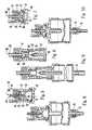
- FIG. 1is a cross-sectional view of a valve of the present invention showing a male cannula fitting drip chamber combined with an “A” clamp;
- FIG. 2is a cross-sectional view of an alternate inserted male cannula fitting drip chamber combined with an “A” clamp;
- FIG. 3is a cross-sectional view of a drip chamber with an embedded cannula fitting combined with a threaded collar fitting;
- FIG. 4is a cross-sectional view of a drip chamber with a cannula combined with a threaded collar fitting
- FIG. 5is a cross-sectional view of one embodiment of the IV component connector
- FIG. 6is a cross-sectional view of another embodiment of the IV component connector
- FIG. 7is a cross-sectional view of yet another embodiment of the IV component connector
- FIG. 8is a cross-sectional view of the connector as shown in FIG. 5 combined with a drip chamber and a proximal end configured as a male luer fitting;
- FIG. 9is a cross-sectional view of the connector as shown in FIG. 6 combined with a drip chamber and a proximal end configured as a solvent bonded IV tube;
- FIG. 10is a cross-sectional view of the connector as shown in FIG. 7 combined with a drip chamber and a proximal end configured as a female luer fitting.
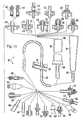
- FIG. 11is a partial cross-sectional view of an IV set of the present invention, showing various drip chamber upper connections and various drip chamber lower connections in exploded relationships.
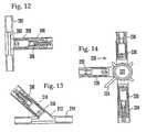
- FIG. 12is a cross-sectional view of a male reflux valve bonded to a “T”-site connector.
- FIG. 13is a cross-sectional view of a male reflux valve bonded to a “Y”-site connector.
- FIG. 14is a plan cross-sectional view of a plurality of reflux valves operably engaged with a stopcock.
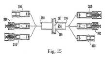
- FIG. 15is an exploded cross-sectional view of various reflux valves in combination with a filter assembly.
- FIG. 16is an exploded isometric view of a four-way valve with various associated components including Luer flags with reflux valves.
- the drip chamber with cannula of the present inventionis shown and is generally designated as 10 .
- the drip chamber 10is made of a plastic (e.g. polypropylene, polyethylene, etc.).
- the drip chamber 10has a distal end 12 which can be engaged with a source of fluid, such as an IV container (not shown).
- a source of fluidsuch as an IV container (not shown).
- the source of fluidcan be any container suitable for holding fluid medicaments, e.g., the source can be an IV bag, vial, IV bottle, semi-rigid container, syringe, etc.
- the drip chamber 10has a proximal end 14 that can be engaged with an IV tube (shown as 39 in FIG. 2 ). Specifically, the IV tube 28 is advanced onto the proximal end 14 of the drip chamber 10 and is held on the proximal end 14 by solvent bonding, rf sealing, ultrasonic welding techniques, or other techniques known by those skilled in the arts.
- the drip chamber 10includes a hollow transparent glass or plastic container 16 , and the container 16 defines a hollow chamber 18 .
- the distal end 12is configured as a cap including a drip forming tube 20 , a cannula 22 formed integrally with a cannula holding element 24 and an attaching mechanism generally designated 26 .
- the attaching mechanism 26is an “A” clamp.
- the “A” clampconsists of two clamp elements 28 a, 28 b.
- the clamp elements 28 a, 28 bare attached to the cannula holding element 24 by two fulcrum bars 30 a, 30 b.
- the “A” clampis biased to the retention configuration shown in the FIGS.
- the clamp elements 28 a, 28 beach have a lip 32 on the distal pincer end to engage a ledge 34 on the fluid source connector port 36 .
- the lip 32is configured with an angular surface 38 to facilitate engagement of the connector port 36 .
- the distal end of the clamp elements 28 a, 28 bcan have bumps 35 a, 35 b to improve the operator's grip while applying pressure to the clamp elements 28 a, 28 b. Squeezing pressure on the clamp elements 28 a, 28 b, below the fulcrum bars 30 a, 30 b, urges the clamp elements 28 a, 28 b, to an open configuration.
- FIG. 2shows an alternate embodiment which is identical to FIG. 1 in all essential respects, except that the cannula 42 is embedded into the cannula holding element 24 . Additionally, FIG. 2 also shows the IV tube 39 inserted into the proximal end 14 of the drip chamber 10 and held in the proximal end 14 by solvent bonding, rf sealing, ultrasonic welding techniques, or other techniques known by those skilled in the arts.
- FIG. 3shows an alternate embodiment which is identical in all essential respects to FIG. 2 except that the attaching mechanism 26 is alternately configured as a threaded collar surrounding the embedded cannula 37 .
- FIG. 4shows an alternate embodiment which is identical in all essential respects to FIG. 1 except that the attachment mechanism 26 is configured as a threaded collar surrounding the integral cannula 22 .
- an IV component connectoris shown and generally designated as 40 .
- the connector 40has a valve body 42 which has a distal end 44 and a proximal end 46 .
- the bodydefines a fluid passageway 48 which provides a pathway for fluid communication through the body 42 .
- the distal end 44is configured as a male fitting for connection to a corresponding female fitting (not shown).
- Fluid communication through the body 42ends at the proximal end 46 where an outlet 50 is provided.
- the proximal end 46attaches to various other IV components as disclosed in issued U.S. Pat. No. 5,645,538 to Richmond and incorporated herein by reference.
- a valve member 52is shown disposed in the body 42 to selectively block the fluid passageway 48 .
- the valve member 52is preferably made from plastic, rubber, etc., and defines an outer periphery that may be interrupted by a fluid orifice 56 .
- a fluid orifice 56may be interrupted by more than one fluid orifice 56 .
- the orifice 56may be shaped in a variety of ways.
- FIG. 5additionally shows that a valve element 60 is reciprocably disposed in the fluid passageway 48 .
- the valve element 60is formed with a lower probe 62 , a retention element 63 and an upper contact flange 64 .
- the lower probe 62exerts pressure, thus opening the valve member 52 as discussed above.
- the retention element 63retains the valve element 60 in the valve body 42 by contacting a surface 66 .
- the distal end 44configured as a male Luer fitting, can be engaged with a complementarily shaped female Luer fitting (not shown).
- This engagementcauses the upper contact flange 64 of the valve element 60 to be contacted by the female Luer fitting (not shown) and to urge the valve element 60 into the valve body 42 .
- the valve element 60When the valve element 60 is urged sufficiently, it contacts the valve member 52 and urges the valve member 52 to the open configuration, thereby allowing fluid communication through the orifice 56 , and hence through the fluid passageway 48 .
- FIG. 6an alternate embodiment of the IV component connector is shown. This is in all essential respects identical to FIG. 5, except that the valve element 60 has a skirt 65 for urging the valve member 52 downwardly and further urging the fluid orifice 56 to the open configuration. Also, as can best be seen in FIG. 6, the valve member 52 need not be rigidly attached to the valve body 42 .
- FIG. 7shows yet another alternative embodiment of the IV component connector of the present invention. This is in all essential respects identical to FIG. 5, except that the valve member 52 can also be held in place by trapping between the separate sub-components of the valve body 42 .
- This Figurealso best illustrates an alternate valve member 52 .
- the distal side of the valve member 52is essentially flat while the proximal side bulges in the center. Said another way, the thickness of the valve member 52 increases towards the center.
- pressure from the proximal side 46 of the valve member 52will cause the valve member 52 to close more tightly. That is, backflow pressure will act to close the valve member 52 and increased pressure will more tightly close the valve 52 .
- FIGS. 8, 9 and 10show the various embodiments of the component connector of the present invention in combination with drip chambers.
- FIG. 8also shows the proximal end configured as a male luer fitting 70 .
- the male luer fitting 70can then be connected and disconnected from a corresponding female fitting 72 .
- FIG. 9shows the proximal end configured as a solvent bonded IV tube 74 .
- FIG. 10shows the proximal end configured as a female luer fitting 76 .
- the female luer fitting 76can then be connected and disconnected from a corresponding male fitting 78 .
- an IV setis shown, generally designated 80 .
- the present IV setincludes a drip chamber, an upper needleless connector on the top of the drip chamber to connect the top to a needleless fitting (such as any of those shown herein), an IV tube connected to the bottom of the drip chamber, a flow restrictor engaged with the IV tube, and a lower needleless connector connected to the end of the IV tube to connect the tube to a needleless fitting (such as any of those shown herein).
- the drip chambercan be an elongated hollow transparent plastic cylindrical drip chamber 82 or tapered drip chamber 84 .
- the present drip chamberis “elongated” in that its length is at least half again as great as its diameter.
- the IV tubeis a hollow plastic IV tube known in the art, with the flow restrictor being an open slide clamp 86 having an open head end 88 (FIG. 11 ).
- an IV tube 102can be connected by attaching the tube 102 by means well-known known in the art to an exit port 104 of the cylindrical drip chamber 82 or to and exit port 106 of the tapered drip chamber 84 .
- the discussion belowwill focus on the cylindrical drip chamber 82 , but it is to be understood that the discussion below is equally relevant to the tapered drip chamber 84 or indeed any well-known drip chamber.
- the open clamp 86can be manipulated by means well-known in the art to constrict the IV tube 102 to stop fluid flow therethrough.
- FIG. 12shows a male member valve 208 which is disposed in a port 210 of a so-called “T”-site connector 202 .
- the T-site connector 202defines a main fluid passageway 204 and a secondary fluid passageway 206 , and the male valve 198 can be manipulated as described above to selectively permit fluid communication through the secondary fluid passageway 206 of the T-site connector.
- FIG. 13shows a male member valve 208 which is disposed in a port 210 of a so-called “Y”-site connector 212 .
- the Y-site connector 212defines a main cylindrical fluid passageway 214 and a secondary fluid passageway 216 .
- the valve 208can be operated as disclosed above to selectively block fluid communication through the secondary passageway 216 of the Y-site connector 212 .
- FIG. 14shows an IV stopcock, generally designated 220 .
- the stopcock 220includes a central fluid passageway that is covered by a cover plate 222 , and an operating hand wheel 224 . Additionally, the stopcock 220 can include at least two ports, and can include additional ports.
- the IV componentcan be a tubular IV connector 290 having a filter 292 disposed athwart a fluid passageway 294 defined by the connector 290 .
- the connector 290has an inlet port 296 and an outlet port 298 .
- the inlet port 296can be selectively blocked by engaging the port 296 with any one of a female member valve 300 , a first male member valve 302 , or a second male member valve 304 .
- the outlet port 298can be selectively blocked by engaging the port 298 with any one of a female member valve 306 , a first male member valve 308 , or a second male member valve 310 .
- the IV component shown in FIG. 15is resealable, in that upon disconnecting a fitting from the valve member in one of the ports 296 , 298 , fluid flow through the component is prevented by the valve member in the disconnected port.
- the multiport valve 674includes a first port 676 which is generally cylindrically shaped, and a second port 678 which is also generally cylindrically shaped and is configured as a female Luer fitting.
- first port 676which is generally cylindrically shaped
- second port 678which is also generally cylindrically shaped and is configured as a female Luer fitting.
- first and second ports 676 , 678are coaxial and establish a main fluid passageway therebetween.
- a first male Luer valve 680is fixedly engaged with the first port 676 for selectively blocking fluid communication therethrough.
- FIG. 16additionally shows that the multiport valve 674 includes third, fourth, fifth and sixth ports 682 , 684 , 686 , 688 , all of which are generally cylindrically shaped. As shown, the third and fifth ports 682 , 686 are coaxial with each other. Likewise, the fourth and sixth ports 684 , 688 are coaxial with each other. Each of the third through sixth ports 682 , 684 , 686 , 688 defines a respective fluid pathway, and fluid communication through the fluid pathway can be selectively established or otherwise effected as disclosed below.
- a female reflux valve 690can be disposed in the third fluid port 682 for selectively establishing fluid communication through the port 682 and into the main fluid passageway 679 in accordance with principles disclosed previously.
- a combination male reflux valve-check valve 692 , 694can be disposed in the fourth fluid inlet port 684 of the multiport valve 674 .
- the male reflux valve 692can be replaced with a female reflux valve (not shown) which is substantially identical to the female reflux valve 30 shown in FIG. 1 .
- fluid communication through the fifth inlet port 686can be permanently blocked if desired by bonding a plug 696 within the port 686 by means well known in the art.
- the fifth fluid inlet port 686can hold a fluid filter, e.g. a filter 698 .
- the falter 698includes a filter element 700 having a membrane 702 through which air can pass.
- the filter 698also includes a plug element 704 which engages filter element 700 and which holds the filter element 700 within the sixth fluid port 686 .
Landscapes
- Health & Medical Sciences (AREA)
- General Health & Medical Sciences (AREA)
- Animal Behavior & Ethology (AREA)
- Veterinary Medicine (AREA)
- Public Health (AREA)
- Heart & Thoracic Surgery (AREA)
- Hematology (AREA)
- Life Sciences & Earth Sciences (AREA)
- Engineering & Computer Science (AREA)
- Biomedical Technology (AREA)
- Anesthesiology (AREA)
- Vascular Medicine (AREA)
- Pharmacology & Pharmacy (AREA)
- Pulmonology (AREA)
- Infusion, Injection, And Reservoir Apparatuses (AREA)
Abstract
Description
Claims (35)
Priority Applications (4)
| Application Number | Priority Date | Filing Date | Title |
|---|---|---|---|
| US08/768,636US5848994A (en) | 1993-07-28 | 1996-12-18 | IV sets with needleless spikeless fittings and valves |
| US08/883,384US6106502A (en) | 1996-12-18 | 1997-06-26 | IV sets with needleless fittings and valves |
| US09/621,181US6485472B1 (en) | 1998-03-12 | 2000-07-21 | Spikeless connection and drip chamber with valve |
| US10/256,847US20030060779A1 (en) | 1996-12-18 | 2002-09-27 | Spikeless connection and drip chamber with valve |
Applications Claiming Priority (2)
| Application Number | Priority Date | Filing Date | Title |
|---|---|---|---|
| US09/041,566US6206860B1 (en) | 1993-07-28 | 1998-03-12 | Spikeless connection and drip chamber with valve |
| US09/621,181US6485472B1 (en) | 1998-03-12 | 2000-07-21 | Spikeless connection and drip chamber with valve |
Related Parent Applications (2)
| Application Number | Title | Priority Date | Filing Date |
|---|---|---|---|
| US08/768,636Continuation-In-PartUS5848994A (en) | 1993-07-28 | 1996-12-18 | IV sets with needleless spikeless fittings and valves |
| US09/041,566ContinuationUS6206860B1 (en) | 1993-07-28 | 1998-03-12 | Spikeless connection and drip chamber with valve |
Related Child Applications (1)
| Application Number | Title | Priority Date | Filing Date |
|---|---|---|---|
| US10/256,847ContinuationUS20030060779A1 (en) | 1996-12-18 | 2002-09-27 | Spikeless connection and drip chamber with valve |
Publications (1)
| Publication Number | Publication Date |
|---|---|
| US6485472B1true US6485472B1 (en) | 2002-11-26 |
Family
ID=46276893
Family Applications (1)
| Application Number | Title | Priority Date | Filing Date |
|---|---|---|---|
| US09/621,181Expired - Fee RelatedUS6485472B1 (en) | 1993-07-28 | 2000-07-21 | Spikeless connection and drip chamber with valve |
Country Status (1)
| Country | Link |
|---|---|
| US (1) | US6485472B1 (en) |
Cited By (44)
| Publication number | Priority date | Publication date | Assignee | Title |
|---|---|---|---|---|
| US20020143297A1 (en)* | 2001-03-30 | 2002-10-03 | Becton, Dickinson And Company | Adaptor for use with point-of-care testing cartridge |
| US6745998B2 (en) | 2001-08-10 | 2004-06-08 | Alaris Medical Systems, Inc. | Valved male luer |
| US20040138626A1 (en)* | 1996-11-18 | 2004-07-15 | Cote Andrew L. | Luer-activated valve |
| FR2852518A1 (en)* | 2003-03-18 | 2004-09-24 | Endos Pharma | Connector for assembling syringe equipped with needle and transfer component has truncated conical adapter with axial channel for needle |
| US20050087715A1 (en)* | 2001-08-10 | 2005-04-28 | Doyle Mark C. | Valved male luer connector having sequential valve timing |
| US6964406B2 (en) | 2001-08-10 | 2005-11-15 | Alaris Medical Systems, Inc. | Valved male luer |
| US20060089603A1 (en)* | 2004-10-22 | 2006-04-27 | Truitt Tim L | Fluid control device with valve and methods of use |
| US7306566B2 (en) | 2004-09-15 | 2007-12-11 | Cardinal Health 303, Inc. | Needle free blood collection device with male connector valve |
| WO2009152119A1 (en) | 2008-06-09 | 2009-12-17 | Allegiance Corporation | Instillation/aspiration device |
| US7651481B2 (en) | 2004-12-30 | 2010-01-26 | CareFusion 303 Inc. | Self-sealing male connector device with collapsible body |
| US7670322B2 (en) | 2005-02-01 | 2010-03-02 | Icu Medical, Inc. | Check valve for medical Y-site |
| ITMO20080226A1 (en)* | 2008-09-11 | 2010-03-12 | Aries S R L | PERFORATOR DEVICE, PARTICULARLY FOR CONTAINMENT BAGS OF PHYSIOLOGICAL FLUIDS FOR MEDICAL AND SIMILAR USE. |
| US7753338B2 (en) | 2006-10-23 | 2010-07-13 | Baxter International Inc. | Luer activated device with minimal fluid displacement |
| US7758566B2 (en) | 2003-12-30 | 2010-07-20 | Icu Medical, Inc. | Valve assembly |
| US7803139B2 (en) | 2005-07-06 | 2010-09-28 | Icu Medical, Inc. | Medical connector with closeable male luer |
| US7815168B2 (en) | 2006-04-11 | 2010-10-19 | Nypro Inc. | Medical valve with rotating member and method |
| US20100269932A1 (en)* | 2006-08-17 | 2010-10-28 | Richmond Frank M | Resealable Components And Systems |
| US7887519B2 (en) | 2005-01-14 | 2011-02-15 | Nypro Inc. | Valve with internal lifter |
| US7981090B2 (en) | 2006-10-18 | 2011-07-19 | Baxter International Inc. | Luer activated device |
| US7998134B2 (en) | 2007-05-16 | 2011-08-16 | Icu Medical, Inc. | Medical connector |
| US8221363B2 (en) | 2006-10-18 | 2012-07-17 | Baxter Healthcare S.A. | Luer activated device with valve element under tension |
| US8506538B2 (en) | 2007-12-05 | 2013-08-13 | Covidien Lp | Device for reducing microbial contamination |
| US8522832B2 (en) | 2009-07-29 | 2013-09-03 | Icu Medical, Inc. | Fluid transfer devices and methods of use |
| US8568371B2 (en) | 2009-06-22 | 2013-10-29 | Np Medical Inc. | Medical valve with improved back-pressure sealing |
| US20140034186A1 (en)* | 2012-01-26 | 2014-02-06 | Jason G. Krause | Quick change i.v. interface technology |
| US8647310B2 (en) | 2010-05-06 | 2014-02-11 | Icu Medical, Inc. | Medical connector with closeable luer connector |
| US8679090B2 (en) | 2008-12-19 | 2014-03-25 | Icu Medical, Inc. | Medical connector with closeable luer connector |
| US9138572B2 (en) | 2010-06-24 | 2015-09-22 | Np Medical Inc. | Medical valve with fluid volume alteration |
| US9168366B2 (en) | 2008-12-19 | 2015-10-27 | Icu Medical, Inc. | Medical connector with closeable luer connector |
| CN105287210A (en)* | 2015-10-13 | 2016-02-03 | 深圳市桑谷医疗机器人有限公司 | Powder bottle clamping and rotating device |
| CN105287209A (en)* | 2015-10-13 | 2016-02-03 | 深圳市桑谷医疗机器人有限公司 | Mother liquid bottle clamping and rotating device |
| CN105362073A (en)* | 2015-10-13 | 2016-03-02 | 深圳市桑谷医疗机器人有限公司 | Clamping and rotating assembly for mother liquor bottles and powder bottles |
| CN106420349A (en)* | 2016-10-31 | 2017-02-22 | 成都杰仕德科技有限公司 | Automatic penicillin-bottle medicine dispensing system and method |
| US9849236B2 (en) | 2013-11-25 | 2017-12-26 | Icu Medical, Inc. | Methods and systems for filling IV bags with therapeutic fluid |
| US9883987B2 (en) | 2011-12-22 | 2018-02-06 | Icu Medical, Inc. | Fluid transfer devices and methods of use |
| US9933094B2 (en) | 2011-09-09 | 2018-04-03 | Icu Medical, Inc. | Medical connectors with fluid-resistant mating interfaces |
| USD837983S1 (en) | 2015-12-04 | 2019-01-08 | Icu Medical, Inc. | Fluid transfer device |
| USD851745S1 (en) | 2016-07-19 | 2019-06-18 | Icu Medical, Inc. | Medical fluid transfer system |
| US11020541B2 (en) | 2016-07-25 | 2021-06-01 | Icu Medical, Inc. | Systems, methods, and components for trapping air bubbles in medical fluid transfer modules and systems |
| USD930824S1 (en) | 2019-05-20 | 2021-09-14 | Icu Medical, Inc. | Port retention clip |
| USD931441S1 (en) | 2019-05-20 | 2021-09-21 | Icu Medical, Inc. | Port retention clip |
| USD957630S1 (en) | 2019-05-20 | 2022-07-12 | Icu Medical, Inc. | Port retention clip |
| US11590057B2 (en) | 2020-04-03 | 2023-02-28 | Icu Medical, Inc. | Systems, methods, and components for transferring medical fluids |
| US11674614B2 (en) | 2020-10-09 | 2023-06-13 | Icu Medical, Inc. | Fluid transfer device and method of use for same |
Citations (4)
| Publication number | Priority date | Publication date | Assignee | Title |
|---|---|---|---|---|
| US5405333A (en)* | 1992-12-28 | 1995-04-11 | Richmond; Frank M. | Liquid medicament bag with needleless connector fitting using boat assembly |
| US5445623A (en)* | 1993-07-28 | 1995-08-29 | Richmond; Frank M. | Drip chamber with luer fitting |
| US5848994A (en)* | 1993-07-28 | 1998-12-15 | Richmond; Frank M. | IV sets with needleless spikeless fittings and valves |
| US6206860B1 (en)* | 1993-07-28 | 2001-03-27 | Frank M. Richmond | Spikeless connection and drip chamber with valve |
- 2000
- 2000-07-21USUS09/621,181patent/US6485472B1/ennot_activeExpired - Fee Related
Patent Citations (6)
| Publication number | Priority date | Publication date | Assignee | Title |
|---|---|---|---|---|
| US5405333A (en)* | 1992-12-28 | 1995-04-11 | Richmond; Frank M. | Liquid medicament bag with needleless connector fitting using boat assembly |
| US5445623A (en)* | 1993-07-28 | 1995-08-29 | Richmond; Frank M. | Drip chamber with luer fitting |
| US5735826A (en)* | 1993-07-28 | 1998-04-07 | Richmond; Frank M. | Drip chamber with luer fitting |
| US5848994A (en)* | 1993-07-28 | 1998-12-15 | Richmond; Frank M. | IV sets with needleless spikeless fittings and valves |
| US6206860B1 (en)* | 1993-07-28 | 2001-03-27 | Frank M. Richmond | Spikeless connection and drip chamber with valve |
| US5645538A (en)* | 1993-09-16 | 1997-07-08 | Richmond; Frank M. | Needleless valve for use in intravenous infusion |
Cited By (132)
| Publication number | Priority date | Publication date | Assignee | Title |
|---|---|---|---|---|
| US7789864B2 (en) | 1996-11-18 | 2010-09-07 | Nypro Inc. | Luer-activated valve |
| US20040138626A1 (en)* | 1996-11-18 | 2004-07-15 | Cote Andrew L. | Luer-activated valve |
| US20020143297A1 (en)* | 2001-03-30 | 2002-10-03 | Becton, Dickinson And Company | Adaptor for use with point-of-care testing cartridge |
| US7100891B2 (en) | 2001-08-10 | 2006-09-05 | Cardinal Health 303, Inc. | Valved male luer with vacuum feature |
| US6745998B2 (en) | 2001-08-10 | 2004-06-08 | Alaris Medical Systems, Inc. | Valved male luer |
| US20040217315A1 (en)* | 2001-08-10 | 2004-11-04 | Doyle Mark C. | Valved male luer |
| US20050087715A1 (en)* | 2001-08-10 | 2005-04-28 | Doyle Mark C. | Valved male luer connector having sequential valve timing |
| US6964406B2 (en) | 2001-08-10 | 2005-11-15 | Alaris Medical Systems, Inc. | Valved male luer |
| US20060065873A1 (en)* | 2001-08-10 | 2006-03-30 | Doyle Mark C | Valved male luer |
| US7306198B2 (en) | 2001-08-10 | 2007-12-11 | Cardinal Health 303, Inc. | Valved male luer with vacuum feature |
| US7044441B2 (en) | 2001-08-10 | 2006-05-16 | Cardinal Health 303, Inc. | Valved male luer connector having sequential valve timing |
| US20060163514A1 (en)* | 2001-08-10 | 2006-07-27 | Doyle Mark C | Valved male luer with vacuum feature |
| US7182313B2 (en) | 2001-08-10 | 2007-02-27 | Cardinal Health 303, Inc. | Valved male luer |
| US20060202146A1 (en)* | 2001-08-10 | 2006-09-14 | Doyle Mark C | Valved male luer connector having sequential valve timing |
| FR2852518A1 (en)* | 2003-03-18 | 2004-09-24 | Endos Pharma | Connector for assembling syringe equipped with needle and transfer component has truncated conical adapter with axial channel for needle |
| WO2004091701A1 (en)* | 2003-03-18 | 2004-10-28 | Endos Pharma | Device for assembling a syringe with a female luer plug |
| US8066692B2 (en) | 2003-12-30 | 2011-11-29 | Icu Medical, Inc. | Medical male luer connector with increased closing volume |
| US8556868B2 (en) | 2003-12-30 | 2013-10-15 | Icu Medical, Inc. | Syringe with multi-pronged actuator |
| US11266785B2 (en) | 2003-12-30 | 2022-03-08 | Icu Medical, Inc. | Medical connector with internal valve member movable within male projection |
| US9592344B2 (en) | 2003-12-30 | 2017-03-14 | Icu Medical, Inc. | Medical connector with internal valve member movable within male luer projection |
| US10105492B2 (en) | 2003-12-30 | 2018-10-23 | Icu Medical, Inc. | Medical connector with internal valve member movable within male luer projection |
| US9913945B2 (en) | 2003-12-30 | 2018-03-13 | Icu Medical, Inc. | Medical connector with internal valve member movable within male luer projection |
| US9707346B2 (en) | 2003-12-30 | 2017-07-18 | Icu Medical, Inc. | Medical valve connector |
| US7758566B2 (en) | 2003-12-30 | 2010-07-20 | Icu Medical, Inc. | Valve assembly |
| US7306566B2 (en) | 2004-09-15 | 2007-12-11 | Cardinal Health 303, Inc. | Needle free blood collection device with male connector valve |
| US7771383B2 (en) | 2004-10-22 | 2010-08-10 | Medegen, Inc. | Fluid control device with valve and methods of use |
| US9782576B2 (en) | 2004-10-22 | 2017-10-10 | Carefusion 303, Inc. | Fluid control device with valve and methods of use |
| US8715222B2 (en) | 2004-10-22 | 2014-05-06 | Carefusion 303, Inc. | Fluid control device with valve and methods of use |
| US20060089603A1 (en)* | 2004-10-22 | 2006-04-27 | Truitt Tim L | Fluid control device with valve and methods of use |
| US7651481B2 (en) | 2004-12-30 | 2010-01-26 | CareFusion 303 Inc. | Self-sealing male connector device with collapsible body |
| US7887519B2 (en) | 2005-01-14 | 2011-02-15 | Nypro Inc. | Valve with internal lifter |
| US7670322B2 (en) | 2005-02-01 | 2010-03-02 | Icu Medical, Inc. | Check valve for medical Y-site |
| US7931627B2 (en) | 2005-02-01 | 2011-04-26 | Icu Medical, Inc. | Check valve for medical Y-site |
| US9636492B2 (en) | 2005-07-06 | 2017-05-02 | Icu Medical, Inc. | Medical connector with translating rigid internal valve member and narrowed passage |
| US9126028B2 (en) | 2005-07-06 | 2015-09-08 | Icu Medical, Inc. | Medical connector |
| US7803140B2 (en) | 2005-07-06 | 2010-09-28 | Icu Medical, Inc. | Medical connector with closeable male luer |
| US9358379B2 (en) | 2005-07-06 | 2016-06-07 | Icu Medical, Inc. | Medical connector with closeable male luer |
| US7803139B2 (en) | 2005-07-06 | 2010-09-28 | Icu Medical, Inc. | Medical connector with closeable male luer |
| US9724504B2 (en) | 2005-07-06 | 2017-08-08 | Icu Medical, Inc. | Medical connector |
| US8211069B2 (en) | 2005-07-06 | 2012-07-03 | Icu Medical, Inc. | Medical connector with closeable male luer |
| US9126029B2 (en) | 2005-07-06 | 2015-09-08 | Icu Medical, Inc. | Medical connector |
| US8262628B2 (en) | 2005-07-06 | 2012-09-11 | Icu Medical, Inc. | Medical connector with closeable male luer |
| US7815614B2 (en) | 2005-07-06 | 2010-10-19 | Icu Medical, Inc. | Medical connector with closeable male luer |
| US9114242B2 (en) | 2005-07-06 | 2015-08-25 | Icu Medical, Inc. | Medical connector |
| US10842982B2 (en) | 2005-07-06 | 2020-11-24 | Icu Medical, Inc. | Medical connector |
| US9974940B2 (en) | 2005-07-06 | 2018-05-22 | Icu Medical, Inc. | Medical connector |
| US9974939B2 (en) | 2005-07-06 | 2018-05-22 | Icu Medical, Inc. | Medical connector |
| US8777908B2 (en) | 2005-07-06 | 2014-07-15 | Icu Medical, Inc. | Medical connector with closeable male luer |
| US8777909B2 (en) | 2005-07-06 | 2014-07-15 | Icu Medical, Inc. | Medical connector with closeable male luer |
| US8002755B2 (en) | 2006-04-11 | 2011-08-23 | Nypro Inc. | Anti-drawback medical valve and method |
| US7879012B2 (en) | 2006-04-11 | 2011-02-01 | Nypro Inc. | Medical valve with resilient sealing member |
| US8968261B2 (en) | 2006-04-11 | 2015-03-03 | Np Medical Inc. | Medical valve with resilient biasing member |
| US7815168B2 (en) | 2006-04-11 | 2010-10-19 | Nypro Inc. | Medical valve with rotating member and method |
| US7857284B2 (en) | 2006-04-11 | 2010-12-28 | Nypro Inc. | Medical valve with movable member |
| US20100269932A1 (en)* | 2006-08-17 | 2010-10-28 | Richmond Frank M | Resealable Components And Systems |
| US7981090B2 (en) | 2006-10-18 | 2011-07-19 | Baxter International Inc. | Luer activated device |
| US8221363B2 (en) | 2006-10-18 | 2012-07-17 | Baxter Healthcare S.A. | Luer activated device with valve element under tension |
| US7753338B2 (en) | 2006-10-23 | 2010-07-13 | Baxter International Inc. | Luer activated device with minimal fluid displacement |
| US11786715B2 (en) | 2007-05-16 | 2023-10-17 | Icu Medical, Inc. | Medical connector |
| US7998134B2 (en) | 2007-05-16 | 2011-08-16 | Icu Medical, Inc. | Medical connector |
| US10398887B2 (en) | 2007-05-16 | 2019-09-03 | Icu Medical, Inc. | Medical connector |
| US8506538B2 (en) | 2007-12-05 | 2013-08-13 | Covidien Lp | Device for reducing microbial contamination |
| WO2009152119A1 (en) | 2008-06-09 | 2009-12-17 | Allegiance Corporation | Instillation/aspiration device |
| WO2010029129A1 (en)* | 2008-09-11 | 2010-03-18 | Aries S.R.L. | Piercing device for bags containing medical fluids |
| ITMO20080226A1 (en)* | 2008-09-11 | 2010-03-12 | Aries S R L | PERFORATOR DEVICE, PARTICULARLY FOR CONTAINMENT BAGS OF PHYSIOLOGICAL FLUIDS FOR MEDICAL AND SIMILAR USE. |
| US9168366B2 (en) | 2008-12-19 | 2015-10-27 | Icu Medical, Inc. | Medical connector with closeable luer connector |
| US10046154B2 (en) | 2008-12-19 | 2018-08-14 | Icu Medical, Inc. | Medical connector with closeable luer connector |
| US11478624B2 (en) | 2008-12-19 | 2022-10-25 | Icu Medical, Inc. | Medical connector with closeable luer connector |
| US12280230B2 (en) | 2008-12-19 | 2025-04-22 | Icu Medical, Inc. | Medical connector with closeable luer connector |
| US8679090B2 (en) | 2008-12-19 | 2014-03-25 | Icu Medical, Inc. | Medical connector with closeable luer connector |
| US10716928B2 (en) | 2008-12-19 | 2020-07-21 | Icu Medical, Inc. | Medical connector with closeable luer connector |
| US10744314B2 (en) | 2009-06-22 | 2020-08-18 | Np Medical Inc. | Medical valve with improved back-pressure sealing |
| US9259565B2 (en) | 2009-06-22 | 2016-02-16 | Np Medical Inc. | Medical valve with improved back-pressure sealing |
| US8568371B2 (en) | 2009-06-22 | 2013-10-29 | Np Medical Inc. | Medical valve with improved back-pressure sealing |
| US9849274B2 (en) | 2009-06-22 | 2017-12-26 | Np Medical Inc. | Medical valve with improved back-pressure sealing |
| US12186270B2 (en) | 2009-07-29 | 2025-01-07 | Icu Medical, Inc. | Fluid transfer devices and methods of use |
| US8973622B2 (en) | 2009-07-29 | 2015-03-10 | Icu Medical, Inc. | Fluid transfer devices and methods of use |
| US11007119B2 (en) | 2009-07-29 | 2021-05-18 | Icu Medical, Inc. | Fluid transfer devices and methods of use |
| US10314765B2 (en) | 2009-07-29 | 2019-06-11 | Icu Medical, Inc. | Fluid transfer devices and methods of use |
| US9931276B2 (en) | 2009-07-29 | 2018-04-03 | Icu Medical, Inc. | Fluid transfer devices and methods of use |
| US9827163B2 (en) | 2009-07-29 | 2017-11-28 | Icu Medical, Inc. | Fluid transfer devices and methods of use |
| US11806308B2 (en) | 2009-07-29 | 2023-11-07 | Icu Medical, Inc. | Fluid transfer devices and methods of use |
| US9511989B2 (en) | 2009-07-29 | 2016-12-06 | Icu Medical, Inc. | Fluid transfer devices and methods of use |
| US8522832B2 (en) | 2009-07-29 | 2013-09-03 | Icu Medical, Inc. | Fluid transfer devices and methods of use |
| US8647310B2 (en) | 2010-05-06 | 2014-02-11 | Icu Medical, Inc. | Medical connector with closeable luer connector |
| US9138572B2 (en) | 2010-06-24 | 2015-09-22 | Np Medical Inc. | Medical valve with fluid volume alteration |
| US12320453B2 (en) | 2011-09-09 | 2025-06-03 | Icu Medical, Inc. | Medical connector with luer-incompatible connection portion |
| US10156306B2 (en) | 2011-09-09 | 2018-12-18 | Icu Medical, Inc. | Axially engaging medical connector system with fluid-resistant mating interfaces |
| US11168818B2 (en) | 2011-09-09 | 2021-11-09 | Icu Medical, Inc. | Axially engaging medical connector system that inhibits fluid penetration between mating surfaces |
| US9933094B2 (en) | 2011-09-09 | 2018-04-03 | Icu Medical, Inc. | Medical connectors with fluid-resistant mating interfaces |
| USD1042817S1 (en) | 2011-09-09 | 2024-09-17 | Icu Medical, Inc. | Medical connector |
| US11808389B2 (en) | 2011-09-09 | 2023-11-07 | Icu Medical, Inc. | Medical connectors with luer-incompatible connection portions |
| US10697570B2 (en) | 2011-09-09 | 2020-06-30 | Icu Medical, Inc. | Axially engaging medical connector system with diminished fluid remnants |
| US11439571B2 (en) | 2011-12-22 | 2022-09-13 | Icu Medical, Inc. | Fluid transfer devices and methods of use |
| US10314764B2 (en) | 2011-12-22 | 2019-06-11 | Icu Medical, Inc. | Fluid transfer devices and methods of use |
| US12023304B2 (en) | 2011-12-22 | 2024-07-02 | Icu Medical, Inc. | Fluid transfer devices and methods of use |
| US9883987B2 (en) | 2011-12-22 | 2018-02-06 | Icu Medical, Inc. | Fluid transfer devices and methods of use |
| US11439570B2 (en) | 2011-12-22 | 2022-09-13 | Icu Medical, Inc. | Fluid transfer devices and methods of use |
| US20140034186A1 (en)* | 2012-01-26 | 2014-02-06 | Jason G. Krause | Quick change i.v. interface technology |
| US10543151B2 (en)* | 2012-01-26 | 2020-01-28 | Krause Dairy Products, Llc | Quick change I.V. interface technology |
| US11541171B2 (en) | 2013-11-25 | 2023-01-03 | Icu Medical, Inc. | Methods and systems for filling IV bags with therapeutic fluid |
| US9849236B2 (en) | 2013-11-25 | 2017-12-26 | Icu Medical, Inc. | Methods and systems for filling IV bags with therapeutic fluid |
| CN105287210B (en)* | 2015-10-13 | 2018-02-23 | 深圳市桑谷医疗机器人有限公司 | Powder bottle clamps rotating device |
| CN105287210A (en)* | 2015-10-13 | 2016-02-03 | 深圳市桑谷医疗机器人有限公司 | Powder bottle clamping and rotating device |
| CN105287209A (en)* | 2015-10-13 | 2016-02-03 | 深圳市桑谷医疗机器人有限公司 | Mother liquid bottle clamping and rotating device |
| CN105287209B (en)* | 2015-10-13 | 2018-02-23 | 深圳市桑谷医疗机器人有限公司 | Mother liquid multi-cavity bottle clamps rotating device |
| CN105362073B (en)* | 2015-10-13 | 2018-02-23 | 深圳市桑谷医疗机器人有限公司 | Mother liquid multi-cavity bottle powder bottle clamps rotation assembly |
| CN105362073A (en)* | 2015-10-13 | 2016-03-02 | 深圳市桑谷医疗机器人有限公司 | Clamping and rotating assembly for mother liquor bottles and powder bottles |
| US10188849B2 (en) | 2015-12-04 | 2019-01-29 | Icu Medical, Inc. | Systems, methods, and components for transferring medical fluids |
| US11135416B2 (en) | 2015-12-04 | 2021-10-05 | Icu Medical, Inc. | Systems, methods, and components for transferring medical fluids |
| US10420927B2 (en) | 2015-12-04 | 2019-09-24 | Icu Medical, Inc. | Systems, methods, and components for transferring medical fluids |
| USD1018849S1 (en) | 2015-12-04 | 2024-03-19 | Icu Medical, Inc. | Fluid transfer device |
| US11865295B2 (en) | 2015-12-04 | 2024-01-09 | Icu Medical, Inc. | Systems, methods, and components for transferring medical fluids |
| USD948044S1 (en) | 2015-12-04 | 2022-04-05 | Icu Medical, Inc. | Fluid transfer device |
| USD837983S1 (en) | 2015-12-04 | 2019-01-08 | Icu Medical, Inc. | Fluid transfer device |
| USD905228S1 (en) | 2016-07-19 | 2020-12-15 | Icu Medical, Inc. | Medical fluid transfer system |
| USD851745S1 (en) | 2016-07-19 | 2019-06-18 | Icu Medical, Inc. | Medical fluid transfer system |
| USD874644S1 (en) | 2016-07-19 | 2020-02-04 | Icu Medical, Inc. | Medical fluid transfer system |
| USD943732S1 (en) | 2016-07-19 | 2022-02-15 | Icu Medical, Inc. | Medical fluid transfer system |
| US11583637B2 (en) | 2016-07-25 | 2023-02-21 | Icu Medical, Inc. | Systems, methods, and components for trapping air bubbles in medical fluid transfer modules and systems |
| US12280249B2 (en) | 2016-07-25 | 2025-04-22 | Icu Medical, Inc. | Systems, methods, and components for trapping air bubbles in medical fluid transfer modules and systems |
| US11951293B2 (en) | 2016-07-25 | 2024-04-09 | Icu Medical, Inc. | Systems, methods, and components for trapping air bubbles in medical fluid transfer modules and systems |
| US11020541B2 (en) | 2016-07-25 | 2021-06-01 | Icu Medical, Inc. | Systems, methods, and components for trapping air bubbles in medical fluid transfer modules and systems |
| CN106420349A (en)* | 2016-10-31 | 2017-02-22 | 成都杰仕德科技有限公司 | Automatic penicillin-bottle medicine dispensing system and method |
| CN106420349B (en)* | 2016-10-31 | 2019-09-17 | 成都杰仕德科技有限公司 | A kind of cillin bottle automated dispensing system and method |
| USD957630S1 (en) | 2019-05-20 | 2022-07-12 | Icu Medical, Inc. | Port retention clip |
| USD930824S1 (en) | 2019-05-20 | 2021-09-14 | Icu Medical, Inc. | Port retention clip |
| USD931441S1 (en) | 2019-05-20 | 2021-09-21 | Icu Medical, Inc. | Port retention clip |
| US11590057B2 (en) | 2020-04-03 | 2023-02-28 | Icu Medical, Inc. | Systems, methods, and components for transferring medical fluids |
| US12303464B2 (en) | 2020-04-03 | 2025-05-20 | Icu Medical, Inc. | Systems, methods, and components for transferring medical fluids |
| US11674614B2 (en) | 2020-10-09 | 2023-06-13 | Icu Medical, Inc. | Fluid transfer device and method of use for same |
| US12345352B2 (en) | 2020-10-09 | 2025-07-01 | Icu Medical, Inc. | Fluid transfer device and method of use for same |
Similar Documents
| Publication | Publication Date | Title |
|---|---|---|
| US6485472B1 (en) | Spikeless connection and drip chamber with valve | |
| US6206860B1 (en) | Spikeless connection and drip chamber with valve | |
| US20050124942A1 (en) | Spikeless connection and drip chamber with valve | |
| US6106502A (en) | IV sets with needleless fittings and valves | |
| US5848994A (en) | IV sets with needleless spikeless fittings and valves | |
| US20030060779A1 (en) | Spikeless connection and drip chamber with valve | |
| US5735826A (en) | Drip chamber with luer fitting | |
| AU2023200572B2 (en) | Pooling device for single or multiple containers | |
| US6068617A (en) | Needleless valve for use in intravenous infusion | |
| US5445630A (en) | Spike with luer fitting | |
| AU765829B2 (en) | Swabbable needleless low reflux injection port system | |
| US4772273A (en) | Variable-volume vented container | |
| AU2006304654B2 (en) | Conversion device | |
| US20250090424A1 (en) | Transfer device for use with infusion liquid container | |
| US4952210A (en) | Parenteral fluid administration set | |
| US20210236385A1 (en) | Transfer device with user-controlled venting |
Legal Events
| Date | Code | Title | Description |
|---|---|---|---|
| FEPP | Fee payment procedure | Free format text:PAT HOLDER NO LONGER CLAIMS SMALL ENTITY STATUS, ENTITY STATUS SET TO UNDISCOUNTED (ORIGINAL EVENT CODE: STOL); ENTITY STATUS OF PATENT OWNER: LARGE ENTITY | |
| FPAY | Fee payment | Year of fee payment:4 | |
| AS | Assignment | Owner name:CARDINAL HEALTH 303, INC., CALIFORNIA Free format text:CHANGE OF NAME;ASSIGNOR:ALARIS MEDICAL SYSTEMS, INC.;REEL/FRAME:017015/0962 Effective date:20041013 | |
| AS | Assignment | Owner name:CAREFUSION 303, INC.,CALIFORNIA Free format text:CHANGE OF NAME;ASSIGNOR:CARDINAL HEALTH 303, INC.;REEL/FRAME:023800/0598 Effective date:20090801 Owner name:CAREFUSION 303, INC., CALIFORNIA Free format text:CHANGE OF NAME;ASSIGNOR:CARDINAL HEALTH 303, INC.;REEL/FRAME:023800/0598 Effective date:20090801 | |
| FPAY | Fee payment | Year of fee payment:8 | |
| REMI | Maintenance fee reminder mailed | ||
| LAPS | Lapse for failure to pay maintenance fees | ||
| STCH | Information on status: patent discontinuation | Free format text:PATENT EXPIRED DUE TO NONPAYMENT OF MAINTENANCE FEES UNDER 37 CFR 1.362 | |
| FP | Lapsed due to failure to pay maintenance fee | Effective date:20141126 |