US6485455B1 - Catheter steering assembly providing asymmetric left and right curve configurations - Google Patents
Catheter steering assembly providing asymmetric left and right curve configurationsDownload PDFInfo
- Publication number
- US6485455B1 US6485455B1US09/273,044US27304499AUS6485455B1US 6485455 B1US6485455 B1US 6485455B1US 27304499 AUS27304499 AUS 27304499AUS 6485455 B1US6485455 B1US 6485455B1
- Authority
- US
- United States
- Prior art keywords
- steering
- attached
- face
- wire
- cam
- Prior art date
- Legal status (The legal status is an assumption and is not a legal conclusion. Google has not performed a legal analysis and makes no representation as to the accuracy of the status listed.)
- Expired - Fee Related
Links
Images


Classifications
- A—HUMAN NECESSITIES
- A61—MEDICAL OR VETERINARY SCIENCE; HYGIENE
- A61M—DEVICES FOR INTRODUCING MEDIA INTO, OR ONTO, THE BODY; DEVICES FOR TRANSDUCING BODY MEDIA OR FOR TAKING MEDIA FROM THE BODY; DEVICES FOR PRODUCING OR ENDING SLEEP OR STUPOR
- A61M25/00—Catheters; Hollow probes
- A61M25/01—Introducing, guiding, advancing, emplacing or holding catheters
- A61M25/0105—Steering means as part of the catheter or advancing means; Markers for positioning
- A61M25/0133—Tip steering devices
- A61M25/0144—Tip steering devices having flexible regions as a result of inner reinforcement means, e.g. struts or rods
- A—HUMAN NECESSITIES
- A61—MEDICAL OR VETERINARY SCIENCE; HYGIENE
- A61M—DEVICES FOR INTRODUCING MEDIA INTO, OR ONTO, THE BODY; DEVICES FOR TRANSDUCING BODY MEDIA OR FOR TAKING MEDIA FROM THE BODY; DEVICES FOR PRODUCING OR ENDING SLEEP OR STUPOR
- A61M25/00—Catheters; Hollow probes
- A61M25/01—Introducing, guiding, advancing, emplacing or holding catheters
- A61M25/0105—Steering means as part of the catheter or advancing means; Markers for positioning
- A61M25/0133—Tip steering devices
- A61M25/0136—Handles therefor
- A—HUMAN NECESSITIES
- A61—MEDICAL OR VETERINARY SCIENCE; HYGIENE
- A61M—DEVICES FOR INTRODUCING MEDIA INTO, OR ONTO, THE BODY; DEVICES FOR TRANSDUCING BODY MEDIA OR FOR TAKING MEDIA FROM THE BODY; DEVICES FOR PRODUCING OR ENDING SLEEP OR STUPOR
- A61M25/00—Catheters; Hollow probes
- A61M25/01—Introducing, guiding, advancing, emplacing or holding catheters
- A61M25/0105—Steering means as part of the catheter or advancing means; Markers for positioning
- A61M25/0133—Tip steering devices
- A61M25/0147—Tip steering devices with movable mechanical means, e.g. pull wires
- A—HUMAN NECESSITIES
- A61—MEDICAL OR VETERINARY SCIENCE; HYGIENE
- A61N—ELECTROTHERAPY; MAGNETOTHERAPY; RADIATION THERAPY; ULTRASOUND THERAPY
- A61N1/00—Electrotherapy; Circuits therefor
- A61N1/02—Details
- A61N1/04—Electrodes
- A61N1/05—Electrodes for implantation or insertion into the body, e.g. heart electrode
- A61N1/056—Transvascular endocardial electrode systems
- A61N1/0565—Electrode heads
- A—HUMAN NECESSITIES
- A61—MEDICAL OR VETERINARY SCIENCE; HYGIENE
- A61N—ELECTROTHERAPY; MAGNETOTHERAPY; RADIATION THERAPY; ULTRASOUND THERAPY
- A61N1/00—Electrotherapy; Circuits therefor
- A61N1/02—Details
- A61N1/04—Electrodes
- A61N1/06—Electrodes for high-frequency therapy
- A—HUMAN NECESSITIES
- A61—MEDICAL OR VETERINARY SCIENCE; HYGIENE
- A61B—DIAGNOSIS; SURGERY; IDENTIFICATION
- A61B18/00—Surgical instruments, devices or methods for transferring non-mechanical forms of energy to or from the body
- A61B2018/0091—Handpieces of the surgical instrument or device
- A61B2018/00916—Handpieces of the surgical instrument or device with means for switching or controlling the main function of the instrument or device
- A61B2018/0094—Types of switches or controllers
- A61B2018/00952—Types of switches or controllers rotatable
- A—HUMAN NECESSITIES
- A61—MEDICAL OR VETERINARY SCIENCE; HYGIENE
- A61M—DEVICES FOR INTRODUCING MEDIA INTO, OR ONTO, THE BODY; DEVICES FOR TRANSDUCING BODY MEDIA OR FOR TAKING MEDIA FROM THE BODY; DEVICES FOR PRODUCING OR ENDING SLEEP OR STUPOR
- A61M25/00—Catheters; Hollow probes
- A61M25/01—Introducing, guiding, advancing, emplacing or holding catheters
- A61M25/0105—Steering means as part of the catheter or advancing means; Markers for positioning
- A61M25/0133—Tip steering devices
- A61M25/0147—Tip steering devices with movable mechanical means, e.g. pull wires
- A61M2025/015—Details of the distal fixation of the movable mechanical means
- A—HUMAN NECESSITIES
- A61—MEDICAL OR VETERINARY SCIENCE; HYGIENE
- A61M—DEVICES FOR INTRODUCING MEDIA INTO, OR ONTO, THE BODY; DEVICES FOR TRANSDUCING BODY MEDIA OR FOR TAKING MEDIA FROM THE BODY; DEVICES FOR PRODUCING OR ENDING SLEEP OR STUPOR
- A61M25/00—Catheters; Hollow probes
- A61M25/01—Introducing, guiding, advancing, emplacing or holding catheters
- A61M25/0105—Steering means as part of the catheter or advancing means; Markers for positioning
Definitions
- the inventiongenerally relates to steering controls for catheters.
- the inventionrelates to catheters that can be steered and manipulated within interior regions of the body from a location outside the body.
- a physiciansteers a catheter through a main vein or artery (which is typically the femoral artery) into the interior region of the heart that is to be treated.
- the physicianthen further manipulates a steering mechanism to place the electrode carried on the tip of the catheter into direct contact with the tissue that is to be ablated.
- the physiciandirects radio frequency energy into the electrode tip to ablate the tissue and form a lesion.
- Cardiac ablationespecially requires the ability to precisely bend and shape the tip end of the catheter to position the ablation electrode.
- the inventionprovides a catheter having a distal tip section that is bendable at the selection of the user in two different directions.
- the distal tip sectionassumes different predetermined curves when bent in each direction. The degree of bending or shape of the predetermined curve can be adjusted in accordance with the invention.
- the inventionprovides a catheter having a body that is bendable in different first and second directions in response, to external forces.
- the catheterincludes a steering mechanism that is movable in two paths for applying different external bending forces on the body and wherein the forces can be adjusted by providing for a different length of travel paths for causing bending forces in the first and second directions.
- the steering mechanismincludes a first actuator that operates in response to movement of the steering mechanism in the first path.
- the first actuatorbends the body in the first direction into a first adjustable predetermined nonlinear shape.
- the steering mechanismalso includes a second actuator that operates in response to movement of the steering mechanism in the second path.
- the second actuatorbends the body in the second direction into a second adjustable predetermined nonlinear shape.
- the second shapeis different from the first shape.
- the bendable bodyincludes a flexible wire member having left and right faces.
- the steering mechanismincludes left and right steering wires. The distal ends of the steering wires are attached, respectively, to the left and right faces of the wire member.
- the first actuatorplaces the left steering wire into tension to bend the wire member to the left into the first adjustable nonlinear shape.
- the second actuatorplaces the right steering wire into tension to bend the wire member to the right into the second adjustable nonlinear shape.
- the steering wirescause asymmetric bending of the wire member by virtue of the fact that the first and second actuators cause the left and right steering wires to travel different distances.
- the points of attachment of the distal ends of the left and right steering wiresare generally symmetrically spaced on the left and right faces of the wire member. In another arrangement, the points of attachment of the distal ends of the left and right steering wires are generally asymmetrically spaced on the left and right faces of the wire member.
- the steering mechanismincludes a rotatable cam to the lateral edges of which the proximal ends of the left and right steering wires are adjustably attached.
- a lever mechanismrotates the rotatable cam to the left and to the right.
- the first actuatorincludes a first cam surface formed on the left side of the rotatable cam.
- the first cam surfacebears against and tensions the left steering wire in response to rotation of the rotatable cam to the left.
- the second actuatorincludes a second cam surface formed on the right side of the rotatable cam.
- the second cam surfaceis configured differently from the first cam surface and bears against and tensions the right steering wire in response to rotation of the rotatable cam to the right.
- first and second cam facesform curves having different radii.
- the cam facesmay be symmetrical but asymmetric steering is accomplished by adjusting the amount of travel of the steering wires.
- the steering wiresare preferably attached tangentially to the lateral edges of the rotatable cam and can be adjusted so that rotation of the rotatable cam results in a multitude of selectable different left and right curve shapes.
- the control wiresextend through adjustable stop members threaded into threaded openings in the lateral edges of the rotatable cam.
- the proximal ends of the wiresare fixed to terminal blocks that are engaged by the stops upon rotation of the rotatable cam to thereby selectively apply tension to the wires.
- the steering wiresare attached to the terminal blocks by having the ends thereof being bent at an angle exceeding 90°, in fishhook fashion, and being soldered into the blocks.
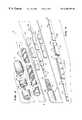
- FIG. 1is a perspective view of a catheter that embodies the features of the invention
- FIG. 2is a top central sectional view of the handle portion of the catheter of FIG. 1 taken generally along Line 2 — 2 with parts broken away for clarity;
- FIG. 3is an exploded view of the electrode tip assembly of the catheter
- FIG. 4is a perspective view of the stiffening assembly for the support wire of the catheter
- FIG. 5is a top view of the catheter in the unbent position with parts broken away to show the steering mechanism
- FIG. 6is top view of the catheter of FIG. 5 steered to the left;
- FIG. 7is a top view of the catheter of FIG. 5 with the steering mechanism adjusted to a different setting and steered to the left at a different curvature;
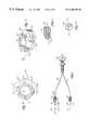
- FIG. 8shows the steering mechanism of the catheter with parts disassembled for clarity
- FIG. 9is a top view of a rotatable cam used in the steering mechanism.
- FIG. 10is a perspective view of the cam shown in FIG. 9;
- FIG. 11is a cross sectional view of the steering wire terminal of the steering mechanism.
- FIG. 12is a cross sectional view taken along Line 12 — 12 of FIG. 8 showing the adjustable stop used in the steering mechanism.
- FIG. 1shows a steerable catheter 10 that embodies the features of the invention.
- the catheter 10includes three main parts or assemblies: the handle assembly 12 , the guide tube assembly 14 , and the electrode tip assembly 16 .
- An electrical cable 48 for providing power to an electrode at the distal tip of the catheterattaches to the back of the housing 20 .
- the catheter 10can be used in many different environments. This specification will describe the catheter 10 as used to provide electrophysiologic therapy in the interior regions of the heart.
- a physiciangrips the handle assembly 12 to steer the guide tube assembly 14 through a main vein or artery (which is typically the femoral arterial) into the interior region of the heart that is to be treated.
- the physicianthen further manipulates a steering mechanism 18 on the handle assembly 12 (which will be described later) to place the electrode tip assembly 16 in contact with the tissue that is to be ablated.
- the physiciandirects radio frequency energy into the electrode tip assembly 16 to ablate the tissue contacting the electrode tip assembly 16 .
- FIG. 2best shows the handle assembly 12 includes a housing 20 that encloses the steering mechanism 18 .
- the steering mechanism 18includes a rotatable cam 23 carried on a screw 24 within the housing 20 .
- the rotatable cam 23is seated for rotation between top washer 26 which bears on a shoulder 27 and a bottom washer. Screw 24 is threaded into a central opening in washer 26 .
- An external steering lever 34is adhesively bonded or ultrasonically welded to the top of the rotatable cam 23 .
- a tab 35 on the steering lever 34is seated in a notch 37 in rotatable cam 23 .
- the steering lever 34also seats against an O-ring (not shown). Further details regarded the O-rings and similar assembly details are described in the above-mentioned copending application Ser. No. 790,207, the entire disclosure of which is herein incorporated by reference.
- Movement of the steering lever 34 by the userrotates the rotatable cam 23 about the screw 24 within the housing 20 .
- Clockwise movement of the steering levelrotates the rotatable cam 23 to the right.
- Counterclockwise movement of the steering wheelrotates the rotatable cam 23 to the left.
- Contact between the steering lever 34 and the side of the housing 20physically limits the range of left and right rotation of the rotatable cam 23 within the housing 20 .
- the steering mechanism 18also includes an external locking lever 38 has hexagonal opening into which the hexagonal head of the screw 24 is seated and bonded by an adhesive.
- the locking lever 38seats against another O-ring. Movement of the locking lever 38 rotates the screw 24 in the threaded opening in washer 26 . Clockwise rotation of the locking lever 38 tightens the screw 24 to increase the seating force on the rotatable cam 23 .
- the locking lever 38When moved fully clockwise into contact against the housing 20 , the locking lever 38 imposes a seating force that restricts rotation of the rotatable cam 23 by the steering lever 34 . Counterclockwise movement of the locking lever 34 loosens the screw 24 to decrease the seating force and free the rotatable cam 23 for rotation.
- the rotatable cam 23includes an asymmetrically shaped forward cam face 41 .
- the forward cam face 41is oriented toward the front of the housing 20 , where the guide tube assembly 14 attaches.
- the forward cam faceincludes a right side cam surface 44 and a left side cam surface 46 .
- Surfaces 44 and 46are located at the bottoms of grooves in the lateral edges of rotatable cam 23 .
- Surfaces 44 and 46may either be of the same (symmetric) radii or may be asymmetrically shaped. In the former instance asymmetric steering of the catheter distal tip is accomplished by adjusting the distance traveled by the steering wires and, as a result, the amount of tension applied thereto.
- the rotatable cam 23is provided on its lateral edges with threaded holes 51 and 53 into which adjustable stops 55 and 57 , respectively, are threaded.
- the proximal ends of right and left catheter steering wires 56 and 58pass through central openings in stops 55 and 57 and are attached to steering wire terminals 59 and 61 .
- Steering wires 56 and 58are bent in fishhook fashion (at an angle greater than 90° at their proximal ends 65 and are soldered ( 67 ) to the interior of the terminal blocks 59 and 61 (as best seen in FIGS. 8 and 11) in order to firmly anchor the wire ends within the terminal blocks.
- stops 55 and 57are provided with a flattened proximal end 63 which can be engaged by a wrench or similar tool in order to rotate the stops and thus adjust the distance that the stops extend proximally from the edges of rotatable cam 23 .
- the steering wires 56 and 58extend from the stops 55 and 57 along the associated left and right side surfaces 44 and 46 of the cam face 41 .
- the steering wiresexit the front of the housing 20 through the interior bore of a tension screw assembly 60 .
- the distal ends of the steering wires 56 and 58are attached to the electrode tip assembly 16 . They extend from the tension screw assembly 60 through the guide tube assembly 14 to the electrode tip assembly 16 .
- adjustable wire stops 55 , 57 in association with the terminal blocks 59 , 61 and cam faces 44 and 46translate rotation of the rotatable cam 23 into lateral pulling movement of the steering wires 56 and 58 attached to the electrode tip assembly 16 .
- Rotation of the tension screw assembly 60additionally varies the amount of slack (i.e., tension) in the steering wires 56 and 58 . This controls the responsiveness of the electrode tip assembly 16 to rotation of the rotatable cam 23 .
- the component parts of the handle assembly 12can be constructed of various materials, depending upon the durability needed and the sterilization process used.
- the housing 20 and bottom washer 28can be made of a polycarbonate material.
- the rotatable cam 23 , steering lever 34 , and locking lever 38can be made of a Delrin material. These plastic materials are durable and EtO sterilizable.
- the nuts, pins, and screw 24are preferably made of a corrosion resistant metallic material such as brass or stainless steel.
- the guide tube assembly 14includes a flexible shaft 62 attached to the handle assembly 12 .
- the flexible shaft 62encloses an interior bore 64 .
- the steering wires 56 and 58pass through the interior bore 64 .
- the shaft 62may constructed in various ways.
- the shaft 62comprises a length of stainless steel coiled into a flexible spring enclosing the interior bore 64 .
- a sheath 66 of extruded plastic material containing wire braidsencloses the coil.
- the sheath 66is preferably made from a thermoplastic material, such as a polyurethane, a polyolefin or polyetherpolyamide block copolymer.
- the shaft 62comprises a slotted, stainless steel tube enclosing the interior bore. Further details of such slotted shafts are disclosed in pending Lundquist U.S. patent application Ser. No. 07/657,106 filed Feb. 15, 1991 and entitled “Torquable Catheter 10 and Method.”
- the handle assembly 12includes a tubular stem 74 though which the proximal end of the guide tube assembly 14 extends for attachment to the tension screw assembly 60 . Adhesive attaches the proximal end of braided sheath 66 to stem 74 .
- the guide tube assembly 14can be made in various lengths. In the case of cardiac ablation catheters, the guide tube assembly 14 is usually about 100 cm in length.
- a sleeve 76couples the guide tube assembly 14 to the handle assembly 12 .
- Adhesivesecures one end of the sleeve 76 to the handle stem 74 .
- the sleeve 76includes an interior bore that progressively tapers from the handle stem 74 into a tight interference fit about the sheath 66 of the guide tube assembly 14 .
- the exterior of the sleeve 76also tapers, extending about 4 to 5 inches beyond the front of the handle housing 20 .
- the sleeve 76is made of a material having a high coefficient of friction, like Krayton G2703.
- the sleeve 76provides a gripping surface to help the user manipulate the catheter 10 .
- the sleeve 76also significant enhances the transmission of torque from the handle assembly 12 to the electrode tip assembly 16 through the guide tube assembly 14 .
- the electrode tip assembly 16includes a bendable main support wire or spring 78 having left and right faces 78 L and 78 R.
- the main support wire, 78is made of stainless steel flat wire stock in an elongated shape about 0.035 inch wide and about 0.005 inch thick.
- the main support wire 78is about 3 inches in total length.
- the opposite ends of the main support wire 78are cut away to form stepped shoulders 80 and 82 .
- the shoulders 80 and 82are about 0.024 inch wide and aligned along the centerline of the main support wire 78 .
- Each shoulder 80 and 82is about 0.12 inch in length.
- one stepped shoulder 80fits within the distal end of the flexible guide tube shaft 62 to append the electrode tip assembly 16 to the guide tube assembly 14 .
- the left and right faces 78 L and 78 R of the main support wire 78lie in a plane that is generally parallel to the axis about which the rotatable cam 23 rotates. Stated differently, when the user holds the handle assembly 12 in a horizontal plane, the left and right faces 78 L and 78 R of the main support wire 78 lie in a vertical plane.
- the distal end of the left steering wire 58is soldered to the left face 78 L of the main support wire 78 .
- the left steering wire 58bends the main support wire 78 to the left.
- the distal end of the right steering wire 56is soldered to the right face 78 R of the main support wire 78 .
- the right steering wire 56bends the main support wire 78 to the right.
- the stiffness of the main support wire 78is not uniform, but varies along its length. Its stiffest point is near its proximal end region, where it joins the guide tube shaft 62 . Its stiffness is least at the tip end 88 of the shoulder 82 .
- the stiffness of the main support wire 78between its proximal end and its distal tip end 88 , the base of the electrode tip assembly 16 (where it joins the guide tube assembly 14 ) resists bending and buckling.
- the bending forces generated by the steering wires 56 and 58are directed toward the distal tip end 88 of the main support wire 78 .
- the variable stiffness of the main support wire 78concentrates the bending forces at the distal tip end 88 of the electrode tip assembly 16 .
- One wayis to vary the thickness of the main support wire 78 as it is manufactured, so that it is thickest (i.e., most stiff) near the shoulder 80 that, in use, is fitted within the guide tube shaft 62 .
- a stiffening spring assembly 90stiffens the center support near the distal end of the guide tube shaft 62 .
- the stiffening spring assembly 90includes two leaf springs 92 that sandwich the main support wire 78 between them.
- Each leaf spring 92is made of stainless steel flat wire stock in an elongated shape that is about 0.035 inch wide and about 0.0025 inch thick.
- the stiffening spring assembly 90can be sized and configured to provide the degrees of stiffness and variance wanted. In the illustrated embodiment, the stiffening spring assembly 90 stiffens the main support wire 78 beginning about 0.030 to 0.050 inch from the inner edge of the attachment shoulder 80 and extending from there about 1.5 inches.
- spot welds 94secure the leaf springs 92 to the main support wire 78 .
- the three spot welds 94 shownare clustered near the proximal end of the stiffening spring assembly 90 . There, they are evenly spaced, with the most distal spot weld 94 being about 0.10 inch from the proximal end of the stiffening spring assembly 90 .
- the distal end of the electrode tip assembly 16carries an ablation tip electrode 96 and three ring electrodes 98 .
- Interior conducting wires 100are connected to the tip electrode 96 and, the three ring electrodes 98 .
- the conducting wires 100extend along the main support wire 78 , through the interior bore of the guide tube shaft 62 , and into the handle housing 20 to join the cable 48 that extends from the rear of the housing 20 .
- the cable 48ends with plugs 102 .
- the plugs 102connect with appropriate conventional catheter control equipment (not shown).
- the conducting wires 100transfer electrical current from the ring electrodes 98 indicative of electrical activity within the heart.
- the conducting wires 100also transfer radio frequency energy to the tip electrode 96 to carry out ablation procedures within the heart.
- the illustrated embodimentemploys a reinforcing sleeve assembly 104 for this purpose.
- the reinforcing sleeve assembly 104holds the steering wires 56 and 58 in close intimate contact against the main support wire 78 . Isolation of the conducting wires 100 from the steering wires 56 and 58 prevents kinking and chafing of the conducting wires 100 during bending operations.
- shrink tubes 114can be made from medical grade TFE Teflon material having a 2 to 1 shrink ratio.
- a reinforcing fabric 116is wrapped in tension over first tube 114 as a single spiral about the tube 114 to obtain a desired, closely spaced pitch.
- the fabric 116is wrapped to a pitch of about 18 to 20 wraps per inch.
- the preferred materialhas a wall thickness (after heat shrinkage) of about 0.003 to 0.0045 inch.
- the fabric 116is a Kevlar 49 Yarn (which is available from DuPont) . This material has a tensile strength of about 410,000 lbs/in 2 and a modulus of about 18,000,000 lbs/in 2 .
- An outer tube 120covers the reinforcing sleeve assembly 104 .
- the tip electrode 96is soldered to the center support 78 and ring electrodes 98 are attached to the conducting wires 100 and joined to the outer tube 120 by conventional methods to complete the electrode tip assembly 16 .
- the curvature assumed upon bending the electrode tip assembly 16 to the leftis different than the curvature assumed upon bending the electrode tip assembly 16 to the right.
- the electrode tip assembly 16assumes one curvature when bent to the left and a different curvature when bent to the right. These different left and right curvatures provide the physician with flexibility in steering the tip electrode 96 into position. These differing curvatures as referred to herein as asymmetric curves.
- a rotatable camto cause different amounts of travel of the left and right steering wires
- different amounts of travelcan also be caused by means of other mechanisms, as well.
- a rotatable gearcan be intermeshed with a pair of movable toothed racks to form a rack and pinion arrangement.
- the two rackscan be configured differently, or provided with stops to limit the travel in one direction more than in other.
Landscapes
- Health & Medical Sciences (AREA)
- Life Sciences & Earth Sciences (AREA)
- Engineering & Computer Science (AREA)
- Animal Behavior & Ethology (AREA)
- Veterinary Medicine (AREA)
- Biomedical Technology (AREA)
- Public Health (AREA)
- General Health & Medical Sciences (AREA)
- Heart & Thoracic Surgery (AREA)
- Pulmonology (AREA)
- Biophysics (AREA)
- Anesthesiology (AREA)
- Hematology (AREA)
- Radiology & Medical Imaging (AREA)
- Nuclear Medicine, Radiotherapy & Molecular Imaging (AREA)
- Vascular Medicine (AREA)
- Mechanical Engineering (AREA)
- Cardiology (AREA)
- Media Introduction/Drainage Providing Device (AREA)
Abstract
Description
This application is a continuation of application Ser. No. 08/812,195, filed Mar. 6, 1997, now U.S. Pat. No. 5,891,088, which is a continuation of application Ser. No. 08/632,762, filed Apr. 16, 1996, now abandoned, which is a continuation of application Ser. No. 08/324,585, filed Oct. 18, 1994, now abandoned, which is a continuation of application Ser. No. 08/058,319, filed May 6, 1993, now U.S. Pat. No. 5,358,478, which is a continuation-in-part of application Ser. No. 07/790,207, filed Nov. 8, 1991, now U.S. Pat. No. 5,273,535, and a continuation-in-part of application Ser. No. 07/991,474, filed Dec. 16, 1992, now U.S. Pat. No. 5,254,088, which is a continuation of application Ser. No. 07/736,384, filed Jul. 26, 1991, now abandoned, which, is a divisional application of application Ser. No. 07/473,667, filed Feb. 2, 1990, now abandoned.
The invention generally relates to steering controls for catheters. In a more specific sense, the invention relates to catheters that can be steered and manipulated within interior regions of the body from a location outside the body.
Physicians make widespread use of catheters today in medical procedures to gain access into interior regions of the body. It is important that the physician can control carefully and precisely the movement of the catheter within the body, especially during procedures that ablate tissue within the heart. These procedures, called electrophysiological therapy, are becoming more widespread for treat cardiac rhythm disturbances.
During these procedures, a physician steers a catheter through a main vein or artery (which is typically the femoral artery) into the interior region of the heart that is to be treated. The physician then further manipulates a steering mechanism to place the electrode carried on the tip of the catheter into direct contact with the tissue that is to be ablated. The physician directs radio frequency energy into the electrode tip to ablate the tissue and form a lesion.
Cardiac ablation especially requires the ability to precisely bend and shape the tip end of the catheter to position the ablation electrode.
The invention provides a catheter having a distal tip section that is bendable at the selection of the user in two different directions. The distal tip section assumes different predetermined curves when bent in each direction. The degree of bending or shape of the predetermined curve can be adjusted in accordance with the invention.
The invention provides a catheter having a body that is bendable in different first and second directions in response, to external forces. The catheter includes a steering mechanism that is movable in two paths for applying different external bending forces on the body and wherein the forces can be adjusted by providing for a different length of travel paths for causing bending forces in the first and second directions.
The steering mechanism includes a first actuator that operates in response to movement of the steering mechanism in the first path. The first actuator bends the body in the first direction into a first adjustable predetermined nonlinear shape.
The steering mechanism also includes a second actuator that operates in response to movement of the steering mechanism in the second path. The second actuator bends the body in the second direction into a second adjustable predetermined nonlinear shape. The second shape is different from the first shape.
In one embodiment, the bendable body includes a flexible wire member having left and right faces. In this arrangement, the steering mechanism includes left and right steering wires. The distal ends of the steering wires are attached, respectively, to the left and right faces of the wire member.
In this embodiment, the first actuator places the left steering wire into tension to bend the wire member to the left into the first adjustable nonlinear shape. The second actuator places the right steering wire into tension to bend the wire member to the right into the second adjustable nonlinear shape. The steering wires cause asymmetric bending of the wire member by virtue of the fact that the first and second actuators cause the left and right steering wires to travel different distances.
In one embodiment, the points of attachment of the distal ends of the left and right steering wires are generally symmetrically spaced on the left and right faces of the wire member. In another arrangement, the points of attachment of the distal ends of the left and right steering wires are generally asymmetrically spaced on the left and right faces of the wire member.
In one embodiment, the steering mechanism includes a rotatable cam to the lateral edges of which the proximal ends of the left and right steering wires are adjustably attached. A lever mechanism rotates the rotatable cam to the left and to the right.
In this arrangement, the first actuator includes a first cam surface formed on the left side of the rotatable cam. The first cam surface bears against and tensions the left steering wire in response to rotation of the rotatable cam to the left.
Also in this arrangement, the second actuator includes a second cam surface formed on the right side of the rotatable cam. The second cam surface is configured differently from the first cam surface and bears against and tensions the right steering wire in response to rotation of the rotatable cam to the right.
In one embodiment, the first and second cam faces form curves having different radii. Alternatively, the cam faces may be symmetrical but asymmetric steering is accomplished by adjusting the amount of travel of the steering wires.
The steering wires are preferably attached tangentially to the lateral edges of the rotatable cam and can be adjusted so that rotation of the rotatable cam results in a multitude of selectable different left and right curve shapes. In accordance with the preferred embodiment of the invention the control wires extend through adjustable stop members threaded into threaded openings in the lateral edges of the rotatable cam. The proximal ends of the wires are fixed to terminal blocks that are engaged by the stops upon rotation of the rotatable cam to thereby selectively apply tension to the wires. Preferably the steering wires are attached to the terminal blocks by having the ends thereof being bent at an angle exceeding 90°, in fishhook fashion, and being soldered into the blocks.
FIG. 1 is a perspective view of a catheter that embodies the features of the invention;
FIG. 2 is a top central sectional view of the handle portion of the catheter of FIG. 1 taken generally alongLine 2—2 with parts broken away for clarity;
FIG. 3 is an exploded view of the electrode tip assembly of the catheter;
FIG. 4 is a perspective view of the stiffening assembly for the support wire of the catheter;
FIG. 5 is a top view of the catheter in the unbent position with parts broken away to show the steering mechanism;
FIG. 6 is top view of the catheter of FIG. 5 steered to the left;
FIG. 7 is a top view of the catheter of FIG. 5 with the steering mechanism adjusted to a different setting and steered to the left at a different curvature;
FIG. 8 shows the steering mechanism of the catheter with parts disassembled for clarity;
FIG. 9 is a top view of a rotatable cam used in the steering mechanism;
FIG. 10 is a perspective view of the cam shown in FIG. 9;
FIG. 11 is a cross sectional view of the steering wire terminal of the steering mechanism; and,
FIG. 12 is a cross sectional view taken alongLine 12—12 of FIG. 8 showing the adjustable stop used in the steering mechanism.
FIG. 1 shows a steerable catheter10 that embodies the features of the invention. As there shown, the catheter10 includes three main parts or assemblies: thehandle assembly 12, theguide tube assembly 14, and theelectrode tip assembly 16. Anelectrical cable 48 for providing power to an electrode at the distal tip of the catheter attaches to the back of thehousing 20.
The catheter10 can be used in many different environments. This specification will describe the catheter10 as used to provide electrophysiologic therapy in the interior regions of the heart.
When used for this purpose, a physician grips thehandle assembly 12 to steer theguide tube assembly 14 through a main vein or artery (which is typically the femoral arterial) into the interior region of the heart that is to be treated. The physician then further manipulates asteering mechanism 18 on the handle assembly12 (which will be described later) to place theelectrode tip assembly 16 in contact with the tissue that is to be ablated. The physician directs radio frequency energy into theelectrode tip assembly 16 to ablate the tissue contacting theelectrode tip assembly 16.
As FIG. 2 best shows thehandle assembly 12 includes ahousing 20 that encloses thesteering mechanism 18. Thesteering mechanism 18 includes arotatable cam 23 carried on ascrew 24 within thehousing 20. Therotatable cam 23 is seated for rotation betweentop washer 26 which bears on ashoulder 27 and a bottom washer.Screw 24 is threaded into a central opening inwasher 26. Anexternal steering lever 34 is adhesively bonded or ultrasonically welded to the top of therotatable cam 23. Atab 35 on the steeringlever 34 is seated in anotch 37 inrotatable cam 23. The steeringlever 34 also seats against an O-ring (not shown). Further details regarded the O-rings and similar assembly details are described in the above-mentioned copending application Ser. No. 790,207, the entire disclosure of which is herein incorporated by reference.
Movement of the steeringlever 34 by the user rotates therotatable cam 23 about thescrew 24 within thehousing 20. Clockwise movement of the steering level rotates therotatable cam 23 to the right. Counterclockwise movement of the steering wheel rotates therotatable cam 23 to the left. Contact between the steeringlever 34 and the side of thehousing 20 physically limits the range of left and right rotation of therotatable cam 23 within thehousing 20.
Thesteering mechanism 18 also includes an external locking lever38 has hexagonal opening into which the hexagonal head of thescrew 24 is seated and bonded by an adhesive. The locking lever38 seats against another O-ring. Movement of the locking lever38 rotates thescrew 24 in the threaded opening inwasher 26. Clockwise rotation of the locking lever38 tightens thescrew 24 to increase the seating force on therotatable cam 23. When moved fully clockwise into contact against thehousing 20, the locking lever38 imposes a seating force that restricts rotation of therotatable cam 23 by the steeringlever 34. Counterclockwise movement of the lockinglever 34 loosens thescrew 24 to decrease the seating force and free therotatable cam 23 for rotation.
Therotatable cam 23 includes an asymmetrically shapedforward cam face 41. The forward cam face41 is oriented toward the front of thehousing 20, where theguide tube assembly 14 attaches. The forward cam face includes a rightside cam surface 44 and a leftside cam surface 46.Surfaces rotatable cam 23.Surfaces
Therotatable cam 23 is provided on its lateral edges with threadedholes 51 and53 into which adjustable stops55 and57, respectively, are threaded. The proximal ends of right and leftcatheter steering wires 56 and58, pass through central openings in stops55 and57 and are attached tosteering wire terminals Steering wires 56 and58 are bent in fishhook fashion (at an angle greater than 90° at their proximal ends65 and are soldered (67) to the interior of the terminal blocks59 and61 (as best seen in FIGS. 8 and 11) in order to firmly anchor the wire ends within the terminal blocks. In order to facilitate adjustment of stops55 and57, they are provided with a flattenedproximal end 63 which can be engaged by a wrench or similar tool in order to rotate the stops and thus adjust the distance that the stops extend proximally from the edges ofrotatable cam 23.
Thesteering wires 56 and58 extend from the stops55 and57 along the associated left and right side surfaces44 and46 of thecam face 41. The steering wires exit the front of thehousing 20 through the interior bore of a tension screw assembly60.
As will be described in greater detail later, the distal ends of thesteering wires 56 and58 are attached to theelectrode tip assembly 16. They extend from the tension screw assembly60 through theguide tube assembly 14 to theelectrode tip assembly 16.
As also will be described in greater detail, the adjustable wire stops55,57 in association with the terminal blocks59,61 and cam faces44 and46 translate rotation of therotatable cam 23 into lateral pulling movement of thesteering wires 56 and58 attached to theelectrode tip assembly 16.
By rotating therotatable cam 23 to the left as shown in FIG. 6 (by moving the steeringlever 34 counterclockwise), the left steering wire stop55 bears against theleft terminal block 59 andcam surface 46. This movement tensions theleft steering wire 58 to impose a discrete, constant pulling force that causes theelectrode tip assembly 16 to bend to the left in a desired curvature. If a different degree of curvature is desired, for example, as shown in FIG. 7, stop55 is rotated to extend it distally, thus adjusting the curvature as shown. Also, sincecam surface
By rotating therotatable cam 23 to the right (by moving the steeringlever 34 clockwise), tension is applied to the right steering wire56 in exactly the same manner as described in connection withwire 58, causing theelectrode tip assembly 16 to bend to the right.
Rotation of the tension screw assembly60 additionally varies the amount of slack (i.e., tension) in thesteering wires 56 and58. This controls the responsiveness of theelectrode tip assembly 16 to rotation of therotatable cam 23.
The component parts of thehandle assembly 12 can be constructed of various materials, depending upon the durability needed and the sterilization process used. For example, when ETO sterilization is used, thehousing 20 and bottom washer28 can be made of a polycarbonate material. In this arrangement, therotatable cam 23, steeringlever 34, and locking lever38 can be made of a Delrin material. These plastic materials are durable and EtO sterilizable. In this assembly, the nuts, pins, and screw24 are preferably made of a corrosion resistant metallic material such as brass or stainless steel.
As FIG. 3 shows, theguide tube assembly 14 includes aflexible shaft 62 attached to thehandle assembly 12. Theflexible shaft 62 encloses aninterior bore 64. Thesteering wires 56 and58 pass through the interior bore64.
Theshaft 62 may constructed in various ways. In the embodiment shown in FIG. 3, theshaft 62 comprises a length of stainless steel coiled into a flexible spring enclosing the interior bore64. Asheath 66 of extruded plastic material containing wire braids encloses the coil. Thesheath 66 is preferably made from a thermoplastic material, such as a polyurethane, a polyolefin or polyetherpolyamide block copolymer.
Alternatively theshaft 62 comprises a slotted, stainless steel tube enclosing the interior bore. Further details of such slotted shafts are disclosed in pending Lundquist U.S. patent application Ser. No. 07/657,106 filed Feb. 15, 1991 and entitled “Torquable Catheter10 and Method.”
Thehandle assembly 12 includes atubular stem 74 though which the proximal end of theguide tube assembly 14 extends for attachment to the tension screw assembly60. Adhesive attaches the proximal end ofbraided sheath 66 to stem74. Theguide tube assembly 14 can be made in various lengths. In the case of cardiac ablation catheters, theguide tube assembly 14 is usually about100 cm in length.
As FIGS. 1 and 2 show, asleeve 76 couples theguide tube assembly 14 to thehandle assembly 12. Adhesive secures one end of thesleeve 76 to thehandle stem 74. Thesleeve 76 includes an interior bore that progressively tapers from thehandle stem 74 into a tight interference fit about thesheath 66 of theguide tube assembly 14. The exterior of thesleeve 76 also tapers, extending about 4 to 5 inches beyond the front of thehandle housing 20.
Thesleeve 76 is made of a material having a high coefficient of friction, like Krayton G2703. Thesleeve 76 provides a gripping surface to help the user manipulate the catheter10. When used in association with the slotted tube, thesleeve 76 also significant enhances the transmission of torque from thehandle assembly 12 to theelectrode tip assembly 16 through theguide tube assembly 14.
Theelectrode tip assembly 16 includes a bendable main support wire orspring 78 having left andright faces main support wire 78 is about 3 inches in total length.
The opposite ends of themain support wire 78 are cut away to form steppedshoulders shoulders main support wire 78. Eachshoulder
As FIG. 3 shows, one steppedshoulder 80 fits within the distal end of the flexibleguide tube shaft 62 to append theelectrode tip assembly 16 to theguide tube assembly 14. When properly oriented, the left andright faces main support wire 78 lie in a plane that is generally parallel to the axis about which therotatable cam 23 rotates. Stated differently, when the user holds thehandle assembly 12 in a horizontal plane, the left andright faces main support wire 78 lie in a vertical plane.
As FIG. 3 shows, the distal end of theleft steering wire 58 is soldered to theleft face 78L of themain support wire 78. When pulled by left rotation of therotatable cam 23, theleft steering wire 58 bends themain support wire 78 to the left.
Also, the distal end of the right steering wire56 is soldered to theright face 78R of themain support wire 78. When pulled by right rotation of therotatable cam 23, the right steering wire56 bends themain support wire 78 to the right.
In the illustrated embodiment, the stiffness of themain support wire 78 is not uniform, but varies along its length. Its stiffest point is near its proximal end region, where it joins theguide tube shaft 62. Its stiffness is least at thetip end 88 of theshoulder 82. By varying the stiffness of themain support wire 78 between its proximal end and itsdistal tip end 88, the base of the electrode tip assembly16 (where it joins the guide tube assembly14) resists bending and buckling. The bending forces generated by thesteering wires 56 and58 are directed toward thedistal tip end 88 of themain support wire 78. The variable stiffness of themain support wire 78 concentrates the bending forces at thedistal tip end 88 of theelectrode tip assembly 16.
There are various ways to varying the stiffness of themain support wire 78 along its length. One way (not shown) is to vary the thickness of themain support wire 78 as it is manufactured, so that it is thickest (i.e., most stiff) near theshoulder 80 that, in use, is fitted within theguide tube shaft 62.
In the illustrated and preferred embodiment (see FIG.4), a stiffeningspring assembly 90 stiffens the center support near the distal end of theguide tube shaft 62. The stiffeningspring assembly 90 includes twoleaf springs 92 that sandwich themain support wire 78 between them. Eachleaf spring 92 is made of stainless steel flat wire stock in an elongated shape that is about 0.035 inch wide and about 0.0025 inch thick.
The stiffeningspring assembly 90 can be sized and configured to provide the degrees of stiffness and variance wanted. In the illustrated embodiment, the stiffeningspring assembly 90 stiffens themain support wire 78 beginning about 0.030 to 0.050 inch from the inner edge of theattachment shoulder 80 and extending from there about 1.5 inches.
In the illustrated embodiment,spot welds 94 secure theleaf springs 92 to themain support wire 78. The threespot welds 94 shown are clustered near the proximal end of the stiffeningspring assembly 90. There, they are evenly spaced, with the mostdistal spot weld 94 being about 0.10 inch from the proximal end of the stiffeningspring assembly 90.
In the illustrated embodiment, the distal end of theelectrode tip assembly 16 carries anablation tip electrode 96 and threering electrodes 98.Interior conducting wires 100 are connected to thetip electrode 96 and, the threering electrodes 98. The conductingwires 100 extend along themain support wire 78, through the interior bore of theguide tube shaft 62, and into thehandle housing 20 to join thecable 48 that extends from the rear of thehousing 20.
Thecable 48 ends withplugs 102. Theplugs 102 connect with appropriate conventional catheter control equipment (not shown). The conductingwires 100 transfer electrical current from thering electrodes 98 indicative of electrical activity within the heart. The conductingwires 100 also transfer radio frequency energy to thetip electrode 96 to carry out ablation procedures within the heart.
There are various ways of securing the attachment between theelectrode tip assembly 16 and theguide tube assembly 14. The illustrated embodiment employs a reinforcingsleeve assembly 104 for this purpose. The reinforcingsleeve assembly 104 holds thesteering wires 56 and58 in close intimate contact against themain support wire 78. Isolation of the conductingwires 100 from thesteering wires 56 and58 prevents kinking and chafing of the conductingwires 100 during bending operations.
The materials used to make the reinforcingsleeve assembly 104 can vary. shrink tubes114 can be made from medical grade TFE Teflon material having a 2 to 1 shrink ratio. A reinforcing fabric116 is wrapped in tension over first tube114 as a single spiral about the tube114 to obtain a desired, closely spaced pitch. In the illustrated embodiment the fabric116 is wrapped to a pitch of about 18 to 20 wraps per inch. The preferred material has a wall thickness (after heat shrinkage) of about 0.003 to 0.0045 inch. In the illustrated embodiment, the fabric116 is a Kevlar 49 Yarn (which is available from DuPont) . This material has a tensile strength of about 410,000 lbs/in2and a modulus of about 18,000,000 lbs/in2.
Anouter tube 120 covers the reinforcingsleeve assembly 104. Thetip electrode 96 is soldered to thecenter support 78 andring electrodes 98 are attached to the conductingwires 100 and joined to theouter tube 120 by conventional methods to complete theelectrode tip assembly 16.
In the illustrated embodiment, the curvature assumed upon bending theelectrode tip assembly 16 to the left is different than the curvature assumed upon bending theelectrode tip assembly 16 to the right. Theelectrode tip assembly 16 assumes one curvature when bent to the left and a different curvature when bent to the right. These different left and right curvatures provide the physician with flexibility in steering thetip electrode 96 into position. These differing curvatures as referred to herein as asymmetric curves.
In addition to the use of a rotatable cam to cause different amounts of travel of the left and right steering wires, it is contemplated that such different amounts of travel can also be caused by means of other mechanisms, as well. For example, a rotatable gear can be intermeshed with a pair of movable toothed racks to form a rack and pinion arrangement. In such case the two racks can be configured differently, or provided with stops to limit the travel in one direction more than in other.
Various features of the invention are set forth in the following claims.
Claims (14)
1. A steering assembly for applying bending forces to a flexible body, comprising:
a handle;
a moveable component moveably connected to said handle;
first and second steering wires each having a proximal end attached to said moveable component and a distal end attached to the flexible body, wherein movement of said moveable component in a first direction applies tension to said first steering wire causing the flexible body to bend in a first multitude of selected curved shapes, and movement of said moveable component in a second direction applies tension to said second steering wire causing said flexible body to bend in a second multitude of selected curved shapes, said first multitude of curved shapes being different from said second multitude of curve shapes.
2. The steering assembly ofclaim 1 , comprising a guide tube having a distal end attached to the flexible body and a proximal end attached to said handle.
3. The steering assembly ofclaim 2 , wherein said guide tube comprises a length of wire coiled into a flexible spring, said coiled flexible spring defining an internal bore which encloses said first and said second steering wires.
4. The steering assembly ofclaim 1 , wherein the flexible body comprises a flexible wire member having a left face and a right face, said left face being attached to the distal end of a first one of said first and second steering wires, said right face being attached to the distal end of second one of said first and second steering wires.
5. The steering assembly ofclaim 1 , wherein the respective proximal ends of said first and second steering wires are attached to said moveable component by respective adjustable connections.
6. The steering assembly ofclaim 1 , wherein said moveable component comprises a rotatable cam, a first face of said cam having a different radius of curve that a second face of said cam.
7. The steering assembly ofclaim 6 , wherein
said proximal end of said first steering wire is tangentially attached to a lateral edge of said first face of said cam; and,
said proximal end of said second steering wire is tangentially attached to a lateral edge of said second face of said cam.
8. A steering assembly for applying bending forces to a flexible body, comprising:
a handle;
a moveable component moveably coupled to said handle;
first and second steering wires each having a proximal end attached to said moveable component and a distal end attachable to the flexible body,
wherein the steering assembly is adapted to cause an attached flexible body to bend in a first multitude of selected curved shapes in response to tension in said first steering wire caused by movement of said moveable component in a first direction, and is further adapted to cause an attached flexible body to bend in a second multitude of selected curved shapes in response to tension in said second steering wire caused by movement of said moveable component in a second direction, said first multitude of curved shapes being different from said second multitude of curve shapes.
9. The steering assembly ofclaim 8 , further comprising a guide tube having a distal end attachable to the flexible body and a proximal end attached to said handle.
10. The steering assembly ofclaim 9 , wherein said guide tube comprises a length of wire coiled into a flexible spring, said coiled flexible spring defining an internal bore which encloses said first and said second steering wires.
11. The steering assembly ofclaim 8 , wherein the flexible body comprises a flexible wire member having a left face and a right face, said left face being attached to the distal end of a first one of said first and second steering wires, said right face being attached to the distal end of a second one of said first and second steering wires.
12. The steering assembly ofclaim 8 , wherein the respective proximal ends of said first and second steering wires are attached to said moveable component by respective adjustable connections.
13. The steering assembly ofclaim 8 , wherein said moveable component comprises a rotatable cam, a first face of said cam having a different radius of curvature than a second face of said rotatable cam.
14. The steering assembly ofclaim 13 , wherein
said proximal end of said first steering wire is tangentially attached to a lateral edge of said first face of said cam, and
said proximal end of said second steering wire is tangentially attached to a lateral edge of said second face of said cam.
Priority Applications (1)
| Application Number | Priority Date | Filing Date | Title |
|---|---|---|---|
| US09/273,044US6485455B1 (en) | 1990-02-02 | 1999-03-19 | Catheter steering assembly providing asymmetric left and right curve configurations |
Applications Claiming Priority (9)
| Application Number | Priority Date | Filing Date | Title |
|---|---|---|---|
| US47366790A | 1990-02-02 | 1990-02-02 | |
| US73638491A | 1991-07-26 | 1991-07-26 | |
| US07/790,207US5273535A (en) | 1991-11-08 | 1991-11-08 | Catheter with electrode tip having asymmetric left and right curve configurations |
| US07/991,474US5254088A (en) | 1990-02-02 | 1992-12-16 | Catheter steering mechanism |
| US08/058,319US5358478A (en) | 1990-02-02 | 1993-05-06 | Catheter steering assembly providing asymmetric left and right curve configurations |
| US32458594A | 1994-10-18 | 1994-10-18 | |
| US63276296A | 1996-04-16 | 1996-04-16 | |
| US08/812,195US5891088A (en) | 1990-02-02 | 1997-03-06 | Catheter steering assembly providing asymmetric left and right curve configurations |
| US09/273,044US6485455B1 (en) | 1990-02-02 | 1999-03-19 | Catheter steering assembly providing asymmetric left and right curve configurations |
Related Parent Applications (1)
| Application Number | Title | Priority Date | Filing Date |
|---|---|---|---|
| US08/812,195ContinuationUS5891088A (en) | 1990-02-02 | 1997-03-06 | Catheter steering assembly providing asymmetric left and right curve configurations |
Publications (1)
| Publication Number | Publication Date |
|---|---|
| US6485455B1true US6485455B1 (en) | 2002-11-26 |
Family
ID=27568137
Family Applications (2)
| Application Number | Title | Priority Date | Filing Date |
|---|---|---|---|
| US08/812,195Expired - LifetimeUS5891088A (en) | 1990-02-02 | 1997-03-06 | Catheter steering assembly providing asymmetric left and right curve configurations |
| US09/273,044Expired - Fee RelatedUS6485455B1 (en) | 1990-02-02 | 1999-03-19 | Catheter steering assembly providing asymmetric left and right curve configurations |
Family Applications Before (1)
| Application Number | Title | Priority Date | Filing Date |
|---|---|---|---|
| US08/812,195Expired - LifetimeUS5891088A (en) | 1990-02-02 | 1997-03-06 | Catheter steering assembly providing asymmetric left and right curve configurations |
Country Status (1)
| Country | Link |
|---|---|
| US (2) | US5891088A (en) |
Cited By (87)
| Publication number | Priority date | Publication date | Assignee | Title |
|---|---|---|---|---|
| US20030130598A1 (en)* | 2002-01-07 | 2003-07-10 | Cardiac Pacemaker, Inc. | Steerable guide catheter with pre-shaped rotatable shaft |
| US20040024413A1 (en)* | 2002-07-31 | 2004-02-05 | Lentz David J. | Wire reinforced articulation segment |
| US20040034365A1 (en)* | 2002-08-16 | 2004-02-19 | Lentz David J. | Catheter having articulation system |
| US20040181138A1 (en)* | 2003-03-12 | 2004-09-16 | Gerhard Hindricks | Method for treating tissue |
| US20040193149A1 (en)* | 2003-03-28 | 2004-09-30 | Scimed Life Systems, Inc. | Cooled ablation catheter |
| US20040215139A1 (en)* | 2002-12-20 | 2004-10-28 | Todd Cohen | Apparatus and method for implanting left ventricular pacing leads within the coronary sinus |
| US20050027334A1 (en)* | 2003-07-30 | 2005-02-03 | Lentz David J. | Articulating catheter for cryoablation with reduced diameter section |
| US20050059862A1 (en)* | 2003-09-12 | 2005-03-17 | Scimed Life Systems, Inc. | Cannula with integrated imaging and optical capability |
| US20050059962A1 (en)* | 2003-09-12 | 2005-03-17 | Scimed Life Systems, Inc. | Ablation catheter with tissue protecting assembly |
| US20050059963A1 (en)* | 2003-09-12 | 2005-03-17 | Scimed Life Systems, Inc. | Systems and method for creating transmural lesions |
| US20050065506A1 (en)* | 2003-09-12 | 2005-03-24 | Scimed Life Systems, Inc. | Vacuum-based catheter stabilizer |
| US20050080336A1 (en)* | 2002-07-22 | 2005-04-14 | Ep Medsystems, Inc. | Method and apparatus for time gating of medical images |
| US20050119644A1 (en)* | 2003-12-01 | 2005-06-02 | Koerner Richard J. | Articulating catheter tip with wedge-cuts |
| US20050137661A1 (en)* | 2003-12-19 | 2005-06-23 | Sra Jasbir S. | Method and system of treatment of cardiac arrhythmias using 4D imaging |
| US20050143777A1 (en)* | 2003-12-19 | 2005-06-30 | Sra Jasbir S. | Method and system of treatment of heart failure using 4D imaging |
| US6926714B1 (en) | 2002-02-05 | 2005-08-09 | Jasbir S. Sra | Method for pulmonary vein isolation and catheter ablation of other structures in the left atrium in atrial fibrillation |
| US20050177131A1 (en)* | 2004-02-09 | 2005-08-11 | Lentz David J. | Catheter articulation segment with alternating cuts |
| US20050177132A1 (en)* | 2004-02-09 | 2005-08-11 | Lentz David J. | Catheter articulation segment with alternating cuts |
| US20050182387A1 (en)* | 2004-02-13 | 2005-08-18 | Cardiac Pacemakers, Inc. | Peel-away catheter shaft |
| US20050203410A1 (en)* | 2004-02-27 | 2005-09-15 | Ep Medsystems, Inc. | Methods and systems for ultrasound imaging of the heart from the pericardium |
| US20050277874A1 (en)* | 2004-06-14 | 2005-12-15 | Selkee Thomas V | Steering mechanism for bi-directional catheter |
| US20050277875A1 (en)* | 2004-06-15 | 2005-12-15 | Selkee Thomas V | Steering mechanism for bi-directional catheter |
| US20050283179A1 (en)* | 2004-06-17 | 2005-12-22 | Lentz David J | Introducer sheath |
| US20050288626A1 (en)* | 2004-06-24 | 2005-12-29 | Koerner Richard J | Active system for deflecting a distal portion of a catheter into a hoop configuration |
| US20050288656A1 (en)* | 2004-06-24 | 2005-12-29 | Koerner Richard J | System for bi-directionally controlling the cryo-tip of a cryoablation catheter |
| US20060004350A1 (en)* | 2004-06-30 | 2006-01-05 | Eric Ryba | System and method for varying return pressure to control tip temperature of a cryoablation catheter |
| US20060047245A1 (en)* | 2004-08-24 | 2006-03-02 | Ruchir Sehra | Catheter control unit |
| US20060064054A1 (en)* | 2002-11-15 | 2006-03-23 | Applied Medical Resources Corporation | Longitudinal sheath enforcement |
| US20060142695A1 (en)* | 2004-12-28 | 2006-06-29 | Knudson John C | Long travel steerable catheter actuator |
| US20060217701A1 (en)* | 2005-03-25 | 2006-09-28 | Boston Scientific Scimed, Inc. | Ablation probe with heat sink |
| US20060270976A1 (en)* | 2005-05-31 | 2006-11-30 | Prorhythm, Inc. | Steerable catheter |
| US20060270975A1 (en)* | 2005-05-31 | 2006-11-30 | Prorhythm, Inc. | Steerable catheter |
| US20070021812A1 (en)* | 2001-12-31 | 2007-01-25 | Cardiac Pacemakers, Inc. | Telescoping guide catheter with peel-away outer sheath |
| US20070215268A1 (en)* | 2002-11-15 | 2007-09-20 | Applied Medical Resources Corporation | Method of making medical tubing having variable characteristics using thermal winding |
| US20070244537A1 (en)* | 1997-06-20 | 2007-10-18 | Rassoll Rashidi | Electrophysiology/ablation catheter having second passage |
| US20070260225A1 (en)* | 2002-11-15 | 2007-11-08 | Applied Medical Resources Corporation | Steerable sheath actuator |
| US20070277550A1 (en)* | 2000-08-09 | 2007-12-06 | Cryocor, Inc. | Refrigeration source for a cryoablation catheter |
| US7311705B2 (en) | 2002-02-05 | 2007-12-25 | Medtronic, Inc. | Catheter apparatus for treatment of heart arrhythmia |
| US20080004604A1 (en)* | 2006-05-20 | 2008-01-03 | Darrell Hartwick | Medical device using beam construction and methods |
| US20080086047A1 (en)* | 2003-03-12 | 2008-04-10 | Biosense Webster, Inc. | Deflectable catheter with hinge |
| US20080097139A1 (en)* | 2006-07-14 | 2008-04-24 | Boston Scientific Scimed, Inc. | Systems and methods for treating lung tissue |
| US20080306475A1 (en)* | 2007-06-08 | 2008-12-11 | Lentz David J | Cryo-applicator cross-section configuration |
| US20080312536A1 (en)* | 2007-06-16 | 2008-12-18 | Ep Medsystems, Inc. | Oscillating Phased-Array Ultrasound Imaging Catheter System |
| US7507205B2 (en) | 2004-04-07 | 2009-03-24 | St. Jude Medical, Atrial Fibrillation Division, Inc. | Steerable ultrasound catheter |
| US20090105640A1 (en)* | 2004-12-28 | 2009-04-23 | Bednarek Michael C | Fixed Dimensional and Bi-Directional Steerable Catheter Control Handle |
| USRE40815E1 (en) | 1999-06-25 | 2009-06-30 | Ams Research Corporation | Control system for cryosurgery |
| US7615050B2 (en) | 2005-06-27 | 2009-11-10 | Boston Scientific Scimed, Inc. | Systems and methods for creating a lesion using transjugular approach |
| US7648462B2 (en) | 2002-01-16 | 2010-01-19 | St. Jude Medical, Atrial Fibrillation Division, Inc. | Safety systems and methods for ensuring safe use of intra-cardiac ultrasound catheters |
| US7654958B2 (en) | 2004-04-20 | 2010-02-02 | St. Jude Medical, Atrial Fibrillation Division, Inc. | Method and apparatus for ultrasound imaging with autofrequency selection |
| US20100069834A1 (en)* | 2008-09-16 | 2010-03-18 | Jeffrey William Schultz | Catheter with adjustable deflection sensitivity |
| US7713210B2 (en) | 2004-11-23 | 2010-05-11 | St. Jude Medical, Atrial Fibrillation Division, Inc. | Method and apparatus for localizing an ultrasound catheter |
| US7727228B2 (en) | 2004-03-23 | 2010-06-01 | Medtronic Cryocath Lp | Method and apparatus for inflating and deflating balloon catheters |
| US20100168827A1 (en)* | 2008-12-30 | 2010-07-01 | Schultz Jeffrey W | Deflectable sheath introducer |
| US20100217184A1 (en)* | 2009-02-20 | 2010-08-26 | Boston Scientific Scimed, Inc. | Steerable catheter having intermediate stiffness transition zone |
| WO2010113072A3 (en)* | 2009-04-02 | 2010-12-02 | Vertical Srl | Device with an electro-catheter for inducing a reversible epidural-related nerve injury |
| US7850811B2 (en) | 2002-11-15 | 2010-12-14 | Hart Charles C | Steerable kink-resistant sheath |
| US20110213260A1 (en)* | 2010-02-26 | 2011-09-01 | Pacesetter, Inc. | Crt lead placement based on optimal branch selection and optimal site selection |
| US8052607B2 (en) | 2008-04-22 | 2011-11-08 | St. Jude Medical, Atrial Fibrillation Division, Inc. | Ultrasound imaging catheter with pivoting head |
| US8057394B2 (en) | 2007-06-30 | 2011-11-15 | St. Jude Medical, Atrial Fibrillation Division, Inc. | Ultrasound image processing to render three-dimensional images from two-dimensional images |
| US8070684B2 (en) | 2005-12-14 | 2011-12-06 | St. Jude Medical, Atrial Fibrillation Division, Inc. | Method and system for evaluating valvular function |
| US8187190B2 (en) | 2006-12-14 | 2012-05-29 | St. Jude Medical, Atrial Fibrillation Division, Inc. | Method and system for configuration of a pacemaker and for placement of pacemaker electrodes |
| US8206345B2 (en) | 2005-03-07 | 2012-06-26 | Medtronic Cryocath Lp | Fluid control system for a medical device |
| WO2012158263A1 (en)* | 2011-05-13 | 2012-11-22 | St. Jude Medical, Atrial Fibrillation Division, Inc. | Five degree of freedom ultrasound catheter and catheter control handle |
| US8430864B2 (en) | 2011-02-16 | 2013-04-30 | Biosense Webster, Inc. | Catheter with multiple deflections |
| US8460237B2 (en) | 2011-11-10 | 2013-06-11 | Biosense Webster (Israel), Ltd. | Medical device control handle with multiplying linear motion |
| US8491636B2 (en) | 2004-03-23 | 2013-07-23 | Medtronic Cryopath LP | Method and apparatus for inflating and deflating balloon catheters |
| US8715441B2 (en) | 2004-01-28 | 2014-05-06 | Applied Medical Resources Corporation | Medical tubing having variable characteristics and method of making same |
| WO2014156284A1 (en)* | 2013-03-29 | 2014-10-02 | 日本ライフライン株式会社 | Medical instrument |
| US9101269B2 (en) | 2011-12-15 | 2015-08-11 | Biosense Webster (Israel), Ltd. | Self-holding medical device control handle with cam actuated clutch mechanism |
| US9138561B2 (en) | 2011-12-15 | 2015-09-22 | Imricor Medical Systems, Inc. | MRI compatible handle and steerable sheath |
| US9375550B2 (en) | 2013-03-15 | 2016-06-28 | St. Jude Medical, Atrial Fibrillation Division, Inc. | Catheter actuators providing mechanical advantage |
| US9445784B2 (en) | 2005-09-22 | 2016-09-20 | Boston Scientific Scimed, Inc | Intravascular ultrasound catheter |
| US9717554B2 (en) | 2012-03-26 | 2017-08-01 | Biosense Webster (Israel) Ltd. | Catheter with composite construction |
| US9757538B2 (en) | 2011-12-15 | 2017-09-12 | Imricor Medical Systems, Inc. | MRI compatible control handle for steerable sheath with audible, tactile and/or visual means |
| US9821143B2 (en) | 2011-12-15 | 2017-11-21 | Imricor Medical Systems, Inc. | Steerable sheath including elastomeric member |
| CN108472079A (en)* | 2015-12-16 | 2018-08-31 | 维米康有限责任公司 | Ablation catheter with optical fiber and regulating device |
| EP3510914A1 (en) | 2018-01-15 | 2019-07-17 | Koninklijke Philips N.V. | Device with bendable distal portion and system actuating the distal portion of the device |
| US10639099B2 (en) | 2012-05-25 | 2020-05-05 | Biosense Webster (Israel), Ltd. | Catheter having a distal section with spring sections for biased deflection |
| WO2020123774A1 (en)* | 2018-12-13 | 2020-06-18 | Imricor Medical Systems, Inc. | Steerable sheath deflection mechanism |
| US10751517B1 (en) | 2019-08-14 | 2020-08-25 | Vasoinnovations Inc. | Apparatus and method for advancing catheters or other medical devices through a lumen |
| US10751511B1 (en) | 2019-08-14 | 2020-08-25 | Vasoinnovations Inc. | Devices, systems, and methods for delivering catheters or other medical devices to locations within a patients body |
| US10821267B1 (en) | 2019-08-14 | 2020-11-03 | Vasoinnovations Inc. | Apparatus and method for advancing catheters or other medical devices through a lumen |
| US10828470B1 (en) | 2019-08-14 | 2020-11-10 | Vasoinnovations Inc. | Apparatus and method for advancing catheters or other medical devices through a lumen |
| WO2021137078A1 (en) | 2019-12-30 | 2021-07-08 | Biosense Webster (Israel) Ltd. | Deflection mechanism of an ear-nose-throat tool |
| US11471650B2 (en) | 2019-09-20 | 2022-10-18 | Biosense Webster (Israel) Ltd. | Mechanism for manipulating a puller wire |
| US11878132B2 (en) | 2019-08-14 | 2024-01-23 | Vasoinnovations Inc. | Apparatus and method for advancing catheters or other medical devices through a lumen |
| US11890431B2 (en) | 2017-03-07 | 2024-02-06 | Circa Scientific, Inc. | Steerable guide catheter |
Families Citing this family (113)
| Publication number | Priority date | Publication date | Assignee | Title |
|---|---|---|---|---|
| US5891088A (en)* | 1990-02-02 | 1999-04-06 | Ep Technologies, Inc. | Catheter steering assembly providing asymmetric left and right curve configurations |
| US5820591A (en)* | 1990-02-02 | 1998-10-13 | E. P. Technologies, Inc. | Assemblies for creating compound curves in distal catheter regions |
| US6413234B1 (en) | 1990-02-02 | 2002-07-02 | Ep Technologies, Inc. | Assemblies for creating compound curves in distal catheter regions |
| US6013047A (en)* | 1997-06-19 | 2000-01-11 | Hewlett-Packard Company | Method and apparatus for prevention of fluid intrusion in a probe shaft |
| WO2000076570A2 (en) | 1999-06-15 | 2000-12-21 | Cryocath Technologies, Inc. | Steerable catheter |
| USD440304S1 (en) | 1999-10-27 | 2001-04-10 | Corvascular, Inc. | Direct fluid-delivery system |
| US6391048B1 (en) | 2000-01-05 | 2002-05-21 | Integrated Vascular Systems, Inc. | Integrated vascular device with puncture site closure component and sealant and methods of use |
| US6461364B1 (en) | 2000-01-05 | 2002-10-08 | Integrated Vascular Systems, Inc. | Vascular sheath with bioabsorbable puncture site closure apparatus and methods of use |
| US9579091B2 (en) | 2000-01-05 | 2017-02-28 | Integrated Vascular Systems, Inc. | Closure system and methods of use |
| US8758400B2 (en) | 2000-01-05 | 2014-06-24 | Integrated Vascular Systems, Inc. | Closure system and methods of use |
| US7842068B2 (en) | 2000-12-07 | 2010-11-30 | Integrated Vascular Systems, Inc. | Apparatus and methods for providing tactile feedback while delivering a closure device |
| US6530897B2 (en)* | 2000-04-28 | 2003-03-11 | Mahase Nardeo | Steerable medical catheter with bendable encapsulated metal spring tip fused to polymeric shaft |
| DE60144328D1 (en) | 2000-09-08 | 2011-05-12 | Abbott Vascular Inc | Surgical clamp |
| US6626918B1 (en)* | 2000-10-06 | 2003-09-30 | Medical Technology Group | Apparatus and methods for positioning a vascular sheath |
| US6623510B2 (en) | 2000-12-07 | 2003-09-23 | Integrated Vascular Systems, Inc. | Closure device and methods for making and using them |
| US6695867B2 (en) | 2002-02-21 | 2004-02-24 | Integrated Vascular Systems, Inc. | Plunger apparatus and methods for delivering a closure device |
| US7905900B2 (en) | 2003-01-30 | 2011-03-15 | Integrated Vascular Systems, Inc. | Clip applier and methods of use |
| US7806904B2 (en) | 2000-12-07 | 2010-10-05 | Integrated Vascular Systems, Inc. | Closure device |
| US7211101B2 (en) | 2000-12-07 | 2007-05-01 | Abbott Vascular Devices | Methods for manufacturing a clip and clip |
| US8690910B2 (en) | 2000-12-07 | 2014-04-08 | Integrated Vascular Systems, Inc. | Closure device and methods for making and using them |
| US6522933B2 (en)* | 2001-03-30 | 2003-02-18 | Biosense, Webster, Inc. | Steerable catheter with a control handle having a pulley mechanism |
| US6605086B2 (en) | 2001-05-02 | 2003-08-12 | Cardiac Pacemakers, Inc. | Steerable catheter with torque transfer system |
| US6610058B2 (en) | 2001-05-02 | 2003-08-26 | Cardiac Pacemakers, Inc. | Dual-profile steerable catheter |
| US6652506B2 (en) | 2001-05-04 | 2003-11-25 | Cardiac Pacemakers, Inc. | Self-locking handle for steering a single or multiple-profile catheter |
| US6648875B2 (en) | 2001-05-04 | 2003-11-18 | Cardiac Pacemakers, Inc. | Means for maintaining tension on a steering tendon in a steerable catheter |
| IES20010547A2 (en) | 2001-06-07 | 2002-12-11 | Christy Cummins | Surgical Staple |
| US6591144B2 (en)* | 2001-10-23 | 2003-07-08 | The Administrators Of The Tulane Educational Fund | Steerable catheter and method for locating coronary sinus |
| US20050124898A1 (en)* | 2002-01-16 | 2005-06-09 | Ep Medsystems, Inc. | Method and apparatus for isolating a catheter interface |
| US20080146943A1 (en)* | 2006-12-14 | 2008-06-19 | Ep Medsystems, Inc. | Integrated Beam Former And Isolation For An Ultrasound Probe |
| IES20030424A2 (en) | 2002-06-04 | 2003-12-10 | Robert Stevenson | Blood vessel closure clip and delivery device |
| US20070083118A1 (en)* | 2002-07-22 | 2007-04-12 | Ep Medsystems, Inc. | Method and System For Estimating Cardiac Ejection Volume Using Ultrasound Spectral Doppler Image Data |
| US20050245822A1 (en)* | 2002-07-22 | 2005-11-03 | Ep Medsystems, Inc. | Method and apparatus for imaging distant anatomical structures in intra-cardiac ultrasound imaging |
| US20050256452A1 (en)* | 2002-11-15 | 2005-11-17 | Demarchi Thomas | Steerable vascular sheath |
| US6922579B2 (en)* | 2002-12-12 | 2005-07-26 | Scimed Life Systems, Inc. | La placian electrode |
| US8905937B2 (en) | 2009-02-26 | 2014-12-09 | Integrated Vascular Systems, Inc. | Methods and apparatus for locating a surface of a body lumen |
| US8202293B2 (en) | 2003-01-30 | 2012-06-19 | Integrated Vascular Systems, Inc. | Clip applier and methods of use |
| US8398656B2 (en) | 2003-01-30 | 2013-03-19 | Integrated Vascular Systems, Inc. | Clip applier and methods of use |
| US8758398B2 (en) | 2006-09-08 | 2014-06-24 | Integrated Vascular Systems, Inc. | Apparatus and method for delivering a closure element |
| US7857828B2 (en) | 2003-01-30 | 2010-12-28 | Integrated Vascular Systems, Inc. | Clip applier and methods of use |
| US8821534B2 (en) | 2010-12-06 | 2014-09-02 | Integrated Vascular Systems, Inc. | Clip applier having improved hemostasis and methods of use |
| US7717865B2 (en)* | 2003-09-30 | 2010-05-18 | Boston Scientific Scimed, Inc. | Side loading wire torquing device |
| US7682358B2 (en)* | 2003-10-30 | 2010-03-23 | Medtronic, Inc. | Steerable catheter |
| IES20040368A2 (en) | 2004-05-25 | 2005-11-30 | James E Coleman | Surgical stapler |
| US7553305B2 (en)* | 2005-06-09 | 2009-06-30 | Enpath Medical, Inc. | Push-pull wire anchor |
| US8926633B2 (en) | 2005-06-24 | 2015-01-06 | Abbott Laboratories | Apparatus and method for delivering a closure element |
| US8313497B2 (en) | 2005-07-01 | 2012-11-20 | Abbott Laboratories | Clip applier and methods of use |
| US8920442B2 (en) | 2005-08-24 | 2014-12-30 | Abbott Vascular Inc. | Vascular opening edge eversion methods and apparatuses |
| US9456811B2 (en) | 2005-08-24 | 2016-10-04 | Abbott Vascular Inc. | Vascular closure methods and apparatuses |
| US20070060895A1 (en) | 2005-08-24 | 2007-03-15 | Sibbitt Wilmer L Jr | Vascular closure methods and apparatuses |
| US8968379B2 (en)* | 2005-09-02 | 2015-03-03 | Medtronic Vascular, Inc. | Stent delivery system with multiple evenly spaced pullwires |
| US20070167793A1 (en)* | 2005-12-14 | 2007-07-19 | Ep Medsystems, Inc. | Method and system for enhancing spectral doppler presentation |
| US20070232949A1 (en)* | 2006-03-31 | 2007-10-04 | Ep Medsystems, Inc. | Method For Simultaneous Bi-Atrial Mapping Of Atrial Fibrillation |
| US8808310B2 (en) | 2006-04-20 | 2014-08-19 | Integrated Vascular Systems, Inc. | Resettable clip applier and reset tools |
| US20080009733A1 (en)* | 2006-06-27 | 2008-01-10 | Ep Medsystems, Inc. | Method for Evaluating Regional Ventricular Function and Incoordinate Ventricular Contraction |
| US8556930B2 (en) | 2006-06-28 | 2013-10-15 | Abbott Laboratories | Vessel closure device |
| US7931616B2 (en)* | 2006-10-31 | 2011-04-26 | Biosense Webster, Inc. | Insert molded catheter puller member connectors and method of making |
| US20080146942A1 (en)* | 2006-12-13 | 2008-06-19 | Ep Medsystems, Inc. | Catheter Position Tracking Methods Using Fluoroscopy and Rotational Sensors |
| US20080146940A1 (en)* | 2006-12-14 | 2008-06-19 | Ep Medsystems, Inc. | External and Internal Ultrasound Imaging System |
| US8226681B2 (en) | 2007-06-25 | 2012-07-24 | Abbott Laboratories | Methods, devices, and apparatus for managing access through tissue |
| US8893947B2 (en) | 2007-12-17 | 2014-11-25 | Abbott Laboratories | Clip applier and methods of use |
| US20090157101A1 (en) | 2007-12-17 | 2009-06-18 | Abbott Laboratories | Tissue closure system and methods of use |
| US7841502B2 (en) | 2007-12-18 | 2010-11-30 | Abbott Laboratories | Modular clip applier |
| US9282965B2 (en) | 2008-05-16 | 2016-03-15 | Abbott Laboratories | Apparatus and methods for engaging tissue |
| US8968355B2 (en)* | 2008-08-04 | 2015-03-03 | Covidien Lp | Articulating surgical device |
| US8398676B2 (en) | 2008-10-30 | 2013-03-19 | Abbott Vascular Inc. | Closure device |
| US8323312B2 (en) | 2008-12-22 | 2012-12-04 | Abbott Laboratories | Closure device |
| US8858594B2 (en) | 2008-12-22 | 2014-10-14 | Abbott Laboratories | Curved closure device |
| US8808345B2 (en)* | 2008-12-31 | 2014-08-19 | Medtronic Ardian Luxembourg S.A.R.L. | Handle assemblies for intravascular treatment devices and associated systems and methods |
| US9089311B2 (en) | 2009-01-09 | 2015-07-28 | Abbott Vascular Inc. | Vessel closure devices and methods |
| US9414820B2 (en) | 2009-01-09 | 2016-08-16 | Abbott Vascular Inc. | Closure devices, systems, and methods |
| US9486191B2 (en) | 2009-01-09 | 2016-11-08 | Abbott Vascular, Inc. | Closure devices |
| US9173644B2 (en) | 2009-01-09 | 2015-11-03 | Abbott Vascular Inc. | Closure devices, systems, and methods |
| US20100179589A1 (en) | 2009-01-09 | 2010-07-15 | Abbott Vascular Inc. | Rapidly eroding anchor |
| US20100185234A1 (en) | 2009-01-16 | 2010-07-22 | Abbott Vascular Inc. | Closure devices, systems, and methods |
| US20110054492A1 (en) | 2009-08-26 | 2011-03-03 | Abbott Laboratories | Medical device for repairing a fistula |
| US8303624B2 (en) | 2010-03-15 | 2012-11-06 | Abbott Cardiovascular Systems, Inc. | Bioabsorbable plug |
| US8758399B2 (en) | 2010-08-02 | 2014-06-24 | Abbott Cardiovascular Systems, Inc. | Expandable bioabsorbable plug apparatus and method |
| US8603116B2 (en) | 2010-08-04 | 2013-12-10 | Abbott Cardiovascular Systems, Inc. | Closure device with long tines |
| US8617087B2 (en) | 2010-12-03 | 2013-12-31 | Biosense Webster, Inc. | Control handle with rotational cam mechanism for contraction/deflection of medical device |
| US8792962B2 (en) | 2010-12-30 | 2014-07-29 | Biosense Webster, Inc. | Catheter with single axial sensors |
| WO2012106185A1 (en)* | 2011-01-31 | 2012-08-09 | Boston Scientific Scimed, Inc. | Articulation section with locking |
| US9149276B2 (en) | 2011-03-21 | 2015-10-06 | Abbott Cardiovascular Systems, Inc. | Clip and deployment apparatus for tissue closure |
| US20130012958A1 (en)* | 2011-07-08 | 2013-01-10 | Stanislaw Marczyk | Surgical Device with Articulation and Wrist Rotation |
| US8523808B2 (en)* | 2011-11-18 | 2013-09-03 | Biosense Webster (Israel), Ltd. | Medical device control handle with independent self holding puller wire actuators |
| US9332976B2 (en) | 2011-11-30 | 2016-05-10 | Abbott Cardiovascular Systems, Inc. | Tissue closure device |
| WO2013116444A1 (en)* | 2012-01-31 | 2013-08-08 | Boston Scientific Scimed, Inc. | Medical device having a tensionable coupling |
| JP2015130898A (en)* | 2012-04-27 | 2015-07-23 | テルモ株式会社 | operation member |
| WO2013190475A2 (en)* | 2012-06-19 | 2013-12-27 | Baylis Medical Company Inc. | Steerable medical device handle |
| US9364209B2 (en) | 2012-12-21 | 2016-06-14 | Abbott Cardiovascular Systems, Inc. | Articulating suturing device |
| KR101484491B1 (en)* | 2013-02-04 | 2015-01-20 | (주)세원메디텍 | Video guided Catheter |
| US9849268B2 (en)* | 2013-02-06 | 2017-12-26 | Biosense Webster (Israel), Ltd. | Catheter having flat beam deflection tip with fiber puller members |
| WO2014182855A1 (en)* | 2013-05-07 | 2014-11-13 | St. Jude Medical, Atrial Fibrillation Division, Inc. | Steering actuator for deflectable catheter |
| EP3057517B1 (en)* | 2013-10-15 | 2020-04-08 | Stryker Corporation | Device for creating a void space in a living tissue, the device including a handle with a control knob that can be set regardless of the orientation of the handle |
| US10661057B2 (en) | 2013-12-20 | 2020-05-26 | Baylis Medical Company Inc. | Steerable medical device handle |
| CN105979845B (en)* | 2014-02-07 | 2018-04-10 | 奥林巴斯株式会社 | Endoscope |
| CN106137380B (en)* | 2015-03-30 | 2019-03-08 | 上海微创电生理医疗科技有限公司 | A kind of modular catheter and the radio frequency ablation catheter using the handle |
| US10327757B1 (en)* | 2015-06-17 | 2019-06-25 | Ethicon Llc | Surgical system with endoscope and suturing instrument |
| US9931487B2 (en) | 2015-08-06 | 2018-04-03 | Boston Scientific Scimed, Inc. | Bidirectional steering control apparatus for a catheter |
| US10849521B2 (en) | 2015-12-23 | 2020-12-01 | Biosense Webster (Israel) Ltd. | Multi-layered catheter shaft construction with embedded single axial sensors, and related methods |
| US10675442B2 (en) | 2016-02-08 | 2020-06-09 | Nextern, Inc. | Robotically augmented catheter manipulation handle |
| US10799675B2 (en) | 2016-03-21 | 2020-10-13 | Edwards Lifesciences Corporation | Cam controlled multi-direction steerable handles |
| US11219746B2 (en) | 2016-03-21 | 2022-01-11 | Edwards Lifesciences Corporation | Multi-direction steerable handles for steering catheters |
| KR102215953B1 (en)* | 2016-07-28 | 2021-02-16 | 쿡 메디컬 테크놀러지스 엘엘씨 | Steerable catheter with wire-tensioning mechanism |
| US10357634B2 (en) | 2016-07-28 | 2019-07-23 | Cook Medical Technologies Llc | Steerable catheter with wire-tensioning mechanism |
| CN106137384A (en)* | 2016-08-01 | 2016-11-23 | 周建明 | Lumbar vertebra radio-frequency (RF) ablation needle-like electrode catheter |
| US11357953B2 (en) | 2016-12-22 | 2022-06-14 | Baylis Medical Company Inc. | Feedback mechanisms for a steerable medical device |
| KR102010491B1 (en)* | 2017-04-03 | 2019-08-13 | 아이메디컴(주) | Steerable catheter |
| US11040174B2 (en)* | 2017-09-19 | 2021-06-22 | Edwards Lifesciences Corporation | Multi-direction steerable handles for steering catheters |
| US10967151B2 (en) | 2019-01-01 | 2021-04-06 | Cairdac | Steerable catheter for the implantation of a leadless cardiac capsule |
| US11849986B2 (en) | 2019-04-24 | 2023-12-26 | Stryker Corporation | Systems and methods for off-axis augmentation of a vertebral body |
| US11364365B2 (en) | 2019-05-18 | 2022-06-21 | Cairdac | Delivery system with an operating handle controlling a steerable catheter for the implantation of a leadless cardiac capsule |
| US11654262B2 (en) | 2020-08-26 | 2023-05-23 | Freudenberg Medical, Llc | Handle assembly for controlling a steerable catheter |
| US12396657B2 (en) | 2021-04-29 | 2025-08-26 | Biosense Webster (Israel) Ltd. | Non-linear single axis navigation sensor with strain relief |
Citations (24)
| Publication number | Priority date | Publication date | Assignee | Title |
|---|---|---|---|---|
| US3892228A (en) | 1972-10-06 | 1975-07-01 | Olympus Optical Co | Apparatus for adjusting the flexing of the bending section of an endoscope |
| US3897775A (en) | 1973-09-07 | 1975-08-05 | Olympus Optical Co | Endoscope with facile bending operation |
| US4543090A (en) | 1983-10-31 | 1985-09-24 | Mccoy William C | Steerable and aimable catheter |
| US4723936A (en) | 1986-07-22 | 1988-02-09 | Versaflex Delivery Systems Inc. | Steerable catheter |
| US4758222A (en) | 1985-05-03 | 1988-07-19 | Mccoy William C | Steerable and aimable catheter |
| US4826087A (en) | 1985-02-12 | 1989-05-02 | David Chinery | Manipulative device |
| US4934340A (en) | 1989-06-08 | 1990-06-19 | Hemo Laser Corporation | Device for guiding medical catheters and scopes |
| US4941454A (en) | 1989-10-05 | 1990-07-17 | Welch Allyn, Inc. | Servo actuated steering mechanism for borescope or endoscope |
| US4942866A (en) | 1988-02-22 | 1990-07-24 | Asahi Kogaku Kogyo Kabushiki Kaisha | Bending control apparatus for endoscope |
| US4944727A (en) | 1986-06-05 | 1990-07-31 | Catheter Research, Inc. | Variable shape guide apparatus |
| US4947827A (en)* | 1988-12-30 | 1990-08-14 | Opielab, Inc. | Flexible endoscope |
| US4984581A (en) | 1988-10-12 | 1991-01-15 | Flexmedics Corporation | Flexible guide having two-way shape memory alloy |
| US5055101A (en) | 1983-10-31 | 1991-10-08 | Catheter Research, Inc. | Variable shape guide apparatus |
| US5090956A (en) | 1983-10-31 | 1992-02-25 | Catheter Research, Inc. | Catheter with memory element-controlled steering |
| US5108368A (en) | 1990-01-04 | 1992-04-28 | Pilot Cardiovascular System, Inc. | Steerable medical device |
| US5114402A (en) | 1983-10-31 | 1992-05-19 | Catheter Research, Inc. | Spring-biased tip assembly |
| US5123421A (en) | 1991-01-16 | 1992-06-23 | C. R. Bard, Inc. | Liquid activated steerable catheter guidewire |
| US5254088A (en)* | 1990-02-02 | 1993-10-19 | Ep Technologies, Inc. | Catheter steering mechanism |
| US5273535A (en)* | 1991-11-08 | 1993-12-28 | Ep Technologies, Inc. | Catheter with electrode tip having asymmetric left and right curve configurations |
| US5358479A (en)* | 1993-12-06 | 1994-10-25 | Electro-Catheter Corporation | Multiform twistable tip deflectable catheter |
| US5358478A (en)* | 1990-02-02 | 1994-10-25 | Ep Technologies, Inc. | Catheter steering assembly providing asymmetric left and right curve configurations |
| US5482037A (en)* | 1993-01-18 | 1996-01-09 | X-Trode S.R.L. | Electrode catheter for mapping and operating on cardiac cavities |
| US5820591A (en)* | 1990-02-02 | 1998-10-13 | E. P. Technologies, Inc. | Assemblies for creating compound curves in distal catheter regions |
| US5891088A (en)* | 1990-02-02 | 1999-04-06 | Ep Technologies, Inc. | Catheter steering assembly providing asymmetric left and right curve configurations |
Family Cites Families (7)
| Publication number | Priority date | Publication date | Assignee | Title |
|---|---|---|---|---|
| DE1213571B (en)* | 1964-12-08 | 1966-03-31 | Paul Ritzau | Device for distributing X-ray contrast media or medication in the gastrointestinal tract |
| US3470876A (en)* | 1966-09-28 | 1969-10-07 | John Barchilon | Dirigible catheter |
| JPS5586435A (en)* | 1978-12-22 | 1980-06-30 | Olympus Optical Co | Endoscope |
| IT1235460B (en)* | 1987-07-31 | 1992-07-30 | Confida Spa | FLEXIBLE ENDOSCOPE. |
| DE69122853T2 (en)* | 1990-02-02 | 1997-10-09 | Ep Technologies, Inc., Sunnyvale, Calif. | STEERING MECHANISM FOR CATHETER |
| ATE123957T1 (en)* | 1990-12-07 | 1995-07-15 | Ruesch Willy Ag | MEDICAL INSTRUMENT WITH DIRECTORABLE TIP. |
| US5190050A (en)* | 1991-11-08 | 1993-03-02 | Electro-Catheter Corporation | Tip deflectable steerable catheter |
- 1997
- 1997-03-06USUS08/812,195patent/US5891088A/ennot_activeExpired - Lifetime
- 1999
- 1999-03-19USUS09/273,044patent/US6485455B1/ennot_activeExpired - Fee Related
Patent Citations (24)
| Publication number | Priority date | Publication date | Assignee | Title |
|---|---|---|---|---|
| US3892228A (en) | 1972-10-06 | 1975-07-01 | Olympus Optical Co | Apparatus for adjusting the flexing of the bending section of an endoscope |
| US3897775A (en) | 1973-09-07 | 1975-08-05 | Olympus Optical Co | Endoscope with facile bending operation |
| US5090956A (en) | 1983-10-31 | 1992-02-25 | Catheter Research, Inc. | Catheter with memory element-controlled steering |
| US4543090A (en) | 1983-10-31 | 1985-09-24 | Mccoy William C | Steerable and aimable catheter |
| US5055101A (en) | 1983-10-31 | 1991-10-08 | Catheter Research, Inc. | Variable shape guide apparatus |
| US5114402A (en) | 1983-10-31 | 1992-05-19 | Catheter Research, Inc. | Spring-biased tip assembly |
| US4826087A (en) | 1985-02-12 | 1989-05-02 | David Chinery | Manipulative device |
| US4758222A (en) | 1985-05-03 | 1988-07-19 | Mccoy William C | Steerable and aimable catheter |
| US4944727A (en) | 1986-06-05 | 1990-07-31 | Catheter Research, Inc. | Variable shape guide apparatus |
| US4723936A (en) | 1986-07-22 | 1988-02-09 | Versaflex Delivery Systems Inc. | Steerable catheter |
| US4942866A (en) | 1988-02-22 | 1990-07-24 | Asahi Kogaku Kogyo Kabushiki Kaisha | Bending control apparatus for endoscope |
| US4984581A (en) | 1988-10-12 | 1991-01-15 | Flexmedics Corporation | Flexible guide having two-way shape memory alloy |
| US4947827A (en)* | 1988-12-30 | 1990-08-14 | Opielab, Inc. | Flexible endoscope |
| US4934340A (en) | 1989-06-08 | 1990-06-19 | Hemo Laser Corporation | Device for guiding medical catheters and scopes |
| US4941454A (en) | 1989-10-05 | 1990-07-17 | Welch Allyn, Inc. | Servo actuated steering mechanism for borescope or endoscope |
| US5108368A (en) | 1990-01-04 | 1992-04-28 | Pilot Cardiovascular System, Inc. | Steerable medical device |
| US5254088A (en)* | 1990-02-02 | 1993-10-19 | Ep Technologies, Inc. | Catheter steering mechanism |
| US5358478A (en)* | 1990-02-02 | 1994-10-25 | Ep Technologies, Inc. | Catheter steering assembly providing asymmetric left and right curve configurations |
| US5820591A (en)* | 1990-02-02 | 1998-10-13 | E. P. Technologies, Inc. | Assemblies for creating compound curves in distal catheter regions |
| US5891088A (en)* | 1990-02-02 | 1999-04-06 | Ep Technologies, Inc. | Catheter steering assembly providing asymmetric left and right curve configurations |
| US5123421A (en) | 1991-01-16 | 1992-06-23 | C. R. Bard, Inc. | Liquid activated steerable catheter guidewire |
| US5273535A (en)* | 1991-11-08 | 1993-12-28 | Ep Technologies, Inc. | Catheter with electrode tip having asymmetric left and right curve configurations |
| US5482037A (en)* | 1993-01-18 | 1996-01-09 | X-Trode S.R.L. | Electrode catheter for mapping and operating on cardiac cavities |
| US5358479A (en)* | 1993-12-06 | 1994-10-25 | Electro-Catheter Corporation | Multiform twistable tip deflectable catheter |
Non-Patent Citations (2)
| Title |
|---|
| "Preliminary Report on a New Method of Intestinal Intubation with the Aid of a Flexible Stylet with Controllable Tip", Grafton A. Smith, M.D.; 1949; pp. 817-821; Minneapolis, MN. |
| "Preliminary Report on a New Method of Intestinal Intubation with the Aid of a Flexible Stylet with Controllable Tip", Smith et al., Surgery, vol. 27, No. 6, pp. 817-821.** |
Cited By (188)
| Publication number | Priority date | Publication date | Assignee | Title |
|---|---|---|---|---|
| US8000764B2 (en)* | 1997-06-20 | 2011-08-16 | St. Jude Medical, Atrial Fibrillation Division, Inc. | Electrophysiology/ablation catheter having second passage |
| US20070244537A1 (en)* | 1997-06-20 | 2007-10-18 | Rassoll Rashidi | Electrophysiology/ablation catheter having second passage |
| USRE40815E1 (en) | 1999-06-25 | 2009-06-30 | Ams Research Corporation | Control system for cryosurgery |
| USRE40868E1 (en)* | 1999-06-25 | 2009-08-11 | Cryocor, Inc. | Refrigeration source for a cryoblation catheter |
| US20070277550A1 (en)* | 2000-08-09 | 2007-12-06 | Cryocor, Inc. | Refrigeration source for a cryoablation catheter |
| US20070021812A1 (en)* | 2001-12-31 | 2007-01-25 | Cardiac Pacemakers, Inc. | Telescoping guide catheter with peel-away outer sheath |
| US8126570B2 (en) | 2001-12-31 | 2012-02-28 | Cardiac Pacemakers, Inc. | Telescoping guide catheter with peel-away outer sheath |
| US7697996B2 (en) | 2001-12-31 | 2010-04-13 | Cardiac Pacemakers, Inc. | Telescoping guide catheter with peel-away outer sheath |
| US20100198194A1 (en)* | 2001-12-31 | 2010-08-05 | Manning Frank E | Telescoping Guide Catheter with Peel-Away Outer Sheath |
| US20030130598A1 (en)* | 2002-01-07 | 2003-07-10 | Cardiac Pacemaker, Inc. | Steerable guide catheter with pre-shaped rotatable shaft |
| US7493156B2 (en)* | 2002-01-07 | 2009-02-17 | Cardiac Pacemakers, Inc. | Steerable guide catheter with pre-shaped rotatable shaft |
| US7648462B2 (en) | 2002-01-16 | 2010-01-19 | St. Jude Medical, Atrial Fibrillation Division, Inc. | Safety systems and methods for ensuring safe use of intra-cardiac ultrasound catheters |
| US6926714B1 (en) | 2002-02-05 | 2005-08-09 | Jasbir S. Sra | Method for pulmonary vein isolation and catheter ablation of other structures in the left atrium in atrial fibrillation |
| US7311705B2 (en) | 2002-02-05 | 2007-12-25 | Medtronic, Inc. | Catheter apparatus for treatment of heart arrhythmia |
| US20050080336A1 (en)* | 2002-07-22 | 2005-04-14 | Ep Medsystems, Inc. | Method and apparatus for time gating of medical images |
| US7314446B2 (en) | 2002-07-22 | 2008-01-01 | Ep Medsystems, Inc. | Method and apparatus for time gating of medical images |
| US7004937B2 (en) | 2002-07-31 | 2006-02-28 | Cryocor, Inc. | Wire reinforced articulation segment |
| US20040024413A1 (en)* | 2002-07-31 | 2004-02-05 | Lentz David J. | Wire reinforced articulation segment |
| US20040034365A1 (en)* | 2002-08-16 | 2004-02-19 | Lentz David J. | Catheter having articulation system |
| US20060064054A1 (en)* | 2002-11-15 | 2006-03-23 | Applied Medical Resources Corporation | Longitudinal sheath enforcement |
| US8691035B2 (en) | 2002-11-15 | 2014-04-08 | Applied Medical Resources Corporation | Method of making medical tubing having variable characteristics using thermal winding |
| US20070260225A1 (en)* | 2002-11-15 | 2007-11-08 | Applied Medical Resources Corporation | Steerable sheath actuator |
| US9675378B2 (en) | 2002-11-15 | 2017-06-13 | Applied Medical Resources Corporation | Steerable kink-resistant sheath |
| US20070215268A1 (en)* | 2002-11-15 | 2007-09-20 | Applied Medical Resources Corporation | Method of making medical tubing having variable characteristics using thermal winding |
| US7850811B2 (en) | 2002-11-15 | 2010-12-14 | Hart Charles C | Steerable kink-resistant sheath |
| US8721826B2 (en) | 2002-11-15 | 2014-05-13 | Applied Medical Resources Corporation | Steerable kink-resistant sheath |
| US8529719B2 (en) | 2002-11-15 | 2013-09-10 | Applied Medical Resources Corporation | Method of making medical tubing having variable characteristics using thermal winding |
| US20040215139A1 (en)* | 2002-12-20 | 2004-10-28 | Todd Cohen | Apparatus and method for implanting left ventricular pacing leads within the coronary sinus |
| US10814100B2 (en) | 2003-03-12 | 2020-10-27 | Biosense Webster, Inc. | Deflectable catheter with hinge |
| US8764743B2 (en) | 2003-03-12 | 2014-07-01 | Biosense Webster, Inc. | Deflectable catheter with hinge |
| US8256428B2 (en)* | 2003-03-12 | 2012-09-04 | Biosense Webster, Inc. | Method for treating tissue |
| US9636482B2 (en) | 2003-03-12 | 2017-05-02 | Biosense Webster, Inc. | Deflectable catheter with hinge |
| US10183150B2 (en) | 2003-03-12 | 2019-01-22 | Biosense Webster, Inc. | Deflectable catheter with hinge |
| US20040181138A1 (en)* | 2003-03-12 | 2004-09-16 | Gerhard Hindricks | Method for treating tissue |
| US20080086047A1 (en)* | 2003-03-12 | 2008-04-10 | Biosense Webster, Inc. | Deflectable catheter with hinge |
| US7938828B2 (en) | 2003-03-28 | 2011-05-10 | Boston Scientific Scimed, Inc. | Cooled ablation catheter |
| US20040193149A1 (en)* | 2003-03-28 | 2004-09-30 | Scimed Life Systems, Inc. | Cooled ablation catheter |
| US20050027334A1 (en)* | 2003-07-30 | 2005-02-03 | Lentz David J. | Articulating catheter for cryoablation with reduced diameter section |
| US6926711B2 (en) | 2003-07-30 | 2005-08-09 | Cryocor, Inc. | Articulating catheter for cryoablation with reduced diameter section |
| US8632532B2 (en) | 2003-09-12 | 2014-01-21 | Boston Scientific Scimed, Inc. | Catheter with tissue protecting assembly |
| US20100010487A1 (en)* | 2003-09-12 | 2010-01-14 | Boston Scientific Scimed, Inc. | Catheter with tissue protecting assembly |
| US8221407B2 (en) | 2003-09-12 | 2012-07-17 | Boston Scientific Scimed, Inc. | Catheter with tissue protecting assembly |
| US20050059862A1 (en)* | 2003-09-12 | 2005-03-17 | Scimed Life Systems, Inc. | Cannula with integrated imaging and optical capability |
| US7569052B2 (en) | 2003-09-12 | 2009-08-04 | Boston Scientific Scimed, Inc. | Ablation catheter with tissue protecting assembly |
| US7438714B2 (en) | 2003-09-12 | 2008-10-21 | Boston Scientific Scimed, Inc. | Vacuum-based catheter stabilizer |
| US20050059962A1 (en)* | 2003-09-12 | 2005-03-17 | Scimed Life Systems, Inc. | Ablation catheter with tissue protecting assembly |
| US20070049925A1 (en)* | 2003-09-12 | 2007-03-01 | Boston Scientific Scimed, Inc. | Methods for creating transmural lesions |
| US20050059963A1 (en)* | 2003-09-12 | 2005-03-17 | Scimed Life Systems, Inc. | Systems and method for creating transmural lesions |
| WO2005032388A1 (en) | 2003-09-12 | 2005-04-14 | Boston Scientific Limited | Tissue probe assembly with vacuum-based stabilizer |
| WO2005025438A1 (en) | 2003-09-12 | 2005-03-24 | Boston Scientific Limited | Systems and apparatus for creating transmural lesions |
| US20050065506A1 (en)* | 2003-09-12 | 2005-03-24 | Scimed Life Systems, Inc. | Vacuum-based catheter stabilizer |
| US20050119644A1 (en)* | 2003-12-01 | 2005-06-02 | Koerner Richard J. | Articulating catheter tip with wedge-cuts |
| US20050137661A1 (en)* | 2003-12-19 | 2005-06-23 | Sra Jasbir S. | Method and system of treatment of cardiac arrhythmias using 4D imaging |
| US20050143777A1 (en)* | 2003-12-19 | 2005-06-30 | Sra Jasbir S. | Method and system of treatment of heart failure using 4D imaging |
| US10765832B2 (en) | 2004-01-28 | 2020-09-08 | Applied Medical Resources Corporation | Medical tubing having variable characteristics and method of making same |
| US9987460B2 (en) | 2004-01-28 | 2018-06-05 | Applied Medical Resources Corporation | Medical tubing having variable characteristcs and method of making same |
| US8715441B2 (en) | 2004-01-28 | 2014-05-06 | Applied Medical Resources Corporation | Medical tubing having variable characteristics and method of making same |
| US8092444B2 (en) | 2004-02-09 | 2012-01-10 | Boston Scientific Scimed, Inc. | Catheter articulation segment with alternating cuts |
| US7637903B2 (en) | 2004-02-09 | 2009-12-29 | Cryocor, Inc. | Catheter articulation segment with alternating cuts |
| US20050177131A1 (en)* | 2004-02-09 | 2005-08-11 | Lentz David J. | Catheter articulation segment with alternating cuts |
| US20050177132A1 (en)* | 2004-02-09 | 2005-08-11 | Lentz David J. | Catheter articulation segment with alternating cuts |
| US20100100073A1 (en)* | 2004-02-09 | 2010-04-22 | Cryocor, Inc. | Catheter articulation segment with alternating cuts |
| US20050182387A1 (en)* | 2004-02-13 | 2005-08-18 | Cardiac Pacemakers, Inc. | Peel-away catheter shaft |
| US20050203410A1 (en)* | 2004-02-27 | 2005-09-15 | Ep Medsystems, Inc. | Methods and systems for ultrasound imaging of the heart from the pericardium |
| US8545491B2 (en) | 2004-03-23 | 2013-10-01 | Medtronic Cryocath Lp | Method and apparatus for inflating and deflating balloon catheters |
| US8491636B2 (en) | 2004-03-23 | 2013-07-23 | Medtronic Cryopath LP | Method and apparatus for inflating and deflating balloon catheters |
| US7727228B2 (en) | 2004-03-23 | 2010-06-01 | Medtronic Cryocath Lp | Method and apparatus for inflating and deflating balloon catheters |
| US7507205B2 (en) | 2004-04-07 | 2009-03-24 | St. Jude Medical, Atrial Fibrillation Division, Inc. | Steerable ultrasound catheter |
| US7654958B2 (en) | 2004-04-20 | 2010-02-02 | St. Jude Medical, Atrial Fibrillation Division, Inc. | Method and apparatus for ultrasound imaging with autofrequency selection |
| US8603069B2 (en) | 2004-06-14 | 2013-12-10 | Biosense Webster, Inc. | Steering mechanism for bi-directional catheter |
| EP1607118A1 (en)* | 2004-06-14 | 2005-12-21 | Biosense Webster, Inc. | Steering mechanism for bi-directional catheter |
| US7591799B2 (en) | 2004-06-14 | 2009-09-22 | Biosense Webster, Inc. | Steering mechanism for bi-directional catheter |
| US10493238B2 (en) | 2004-06-14 | 2019-12-03 | Biosense Webster (Israel) Ltd. | Steering mechanism for bi-directional catheter |
| US20050277874A1 (en)* | 2004-06-14 | 2005-12-15 | Selkee Thomas V | Steering mechanism for bi-directional catheter |
| US8021327B2 (en) | 2004-06-14 | 2011-09-20 | Biosense Webster, Inc. | Steering mechanism for bi-directional catheter |
| US9345860B2 (en) | 2004-06-14 | 2016-05-24 | Biosense Webster, Inc. | Steering mechanism for bi-directional catheter |
| US20080255540A1 (en)* | 2004-06-15 | 2008-10-16 | Biosense Webster, Inc. | Steering mechanism for bi-directional catheter |
| US8348888B2 (en) | 2004-06-15 | 2013-01-08 | Biosense Webster, Inc. | Steering mechanism for bi-directional catheter |
| US9474879B2 (en) | 2004-06-15 | 2016-10-25 | Biosense Webster, Inc. | Steering mechanism for bi-directional catheter |
| US8956322B2 (en) | 2004-06-15 | 2015-02-17 | Biosense Webster, Inc. | Steering mechanism for bi-directional catheter |
| US20050277875A1 (en)* | 2004-06-15 | 2005-12-15 | Selkee Thomas V | Steering mechanism for bi-directional catheter |
| US9861790B2 (en) | 2004-06-15 | 2018-01-09 | Biosense Webster, Inc. | Steering mechanism for bi-directional catheter |
| EP1607119A1 (en)* | 2004-06-15 | 2005-12-21 | Biosense Webster, Inc. | Improved steering mechanism for bi-directional catheter |
| US7377906B2 (en)* | 2004-06-15 | 2008-05-27 | Biosense Webster, Inc. | Steering mechanism for bi-directional catheter |
| US20050283179A1 (en)* | 2004-06-17 | 2005-12-22 | Lentz David J | Introducer sheath |
| US7285108B2 (en) | 2004-06-24 | 2007-10-23 | Cryocor, Inc. | Active system for deflecting a distal portion of a catheter into a hoop configuration |
| US20050288626A1 (en)* | 2004-06-24 | 2005-12-29 | Koerner Richard J | Active system for deflecting a distal portion of a catheter into a hoop configuration |
| US20050288656A1 (en)* | 2004-06-24 | 2005-12-29 | Koerner Richard J | System for bi-directionally controlling the cryo-tip of a cryoablation catheter |
| US7374553B2 (en) | 2004-06-24 | 2008-05-20 | Cryocor, Inc. | System for bi-directionally controlling the cryo-tip of a cryoablation catheter |
| US7357797B2 (en) | 2004-06-30 | 2008-04-15 | Cryocor, Inc. | System and method for varying return pressure to control tip temperature of a cryoablation catheter |
| US20060004350A1 (en)* | 2004-06-30 | 2006-01-05 | Eric Ryba | System and method for varying return pressure to control tip temperature of a cryoablation catheter |
| US20060047245A1 (en)* | 2004-08-24 | 2006-03-02 | Ruchir Sehra | Catheter control unit |
| US7713210B2 (en) | 2004-11-23 | 2010-05-11 | St. Jude Medical, Atrial Fibrillation Division, Inc. | Method and apparatus for localizing an ultrasound catheter |
| US10639004B2 (en) | 2004-11-23 | 2020-05-05 | St. Jude Medical, Atrial Fibrillation Division, Inc. | Method and apparatus for localizing an ultrasound catheter |
| US8858495B2 (en) | 2004-12-28 | 2014-10-14 | St. Jude Medical, Atrial Fibrillation Division, Inc. | Five degree of freedom ultrasound catheter and catheter control handle |
| US8583260B2 (en)* | 2004-12-28 | 2013-11-12 | St. Jude Medical, Atrial Fibrillation Division, Inc. | Long travel steerable catheter actuator |
| US10022521B2 (en) | 2004-12-28 | 2018-07-17 | St. Jude Medical, Atrial Fibrillation Division, Inc. | Long travel steerable catheter actuator |
| US10960181B2 (en) | 2004-12-28 | 2021-03-30 | St. Jude Medical, Atrial Fibrillation Division, Inc. | Fixed dimensional and bi-directional steerable catheter control handle |
| US20060142695A1 (en)* | 2004-12-28 | 2006-06-29 | Knudson John C | Long travel steerable catheter actuator |
| US9132258B2 (en) | 2004-12-28 | 2015-09-15 | St. Jude Medical, Atrial Fibrillation Division, Inc. | Fixed dimensional and bi-directional steerable catheter control handle |
| US10035000B2 (en) | 2004-12-28 | 2018-07-31 | St. Jude Medical, Atrial Fibrillation Division, Inc. | Fixed dimensional and bi-directional steerable catheter control handle |
| US20090105640A1 (en)* | 2004-12-28 | 2009-04-23 | Bednarek Michael C | Fixed Dimensional and Bi-Directional Steerable Catheter Control Handle |
| US8323239B2 (en) | 2004-12-28 | 2012-12-04 | St. Jude Medical, Atrial Fibrillation Division, Inc. | Fixed dimensional and bi-directional steerable catheter control handle |
| US10183149B2 (en) | 2004-12-28 | 2019-01-22 | St. Jude Medical, Atrial Fibrillation Division, Inc. | Five degree of freedom ultrasound catheter and catheter control handle |
| US7691095B2 (en)* | 2004-12-28 | 2010-04-06 | St. Jude Medical, Atrial Fibrillation Division, Inc. | Bi-directional steerable catheter control handle |
| US8206345B2 (en) | 2005-03-07 | 2012-06-26 | Medtronic Cryocath Lp | Fluid control system for a medical device |
| US7670336B2 (en) | 2005-03-25 | 2010-03-02 | Boston Scientific Scimed, Inc. | Ablation probe with heat sink |
| US20100130974A1 (en)* | 2005-03-25 | 2010-05-27 | Boston Scientific Scimed, Inc. | Ablation probe with heat sink |
| US20060217701A1 (en)* | 2005-03-25 | 2006-09-28 | Boston Scientific Scimed, Inc. | Ablation probe with heat sink |
| US8007497B2 (en) | 2005-03-25 | 2011-08-30 | Boston Scientific Scimed, Inc. | Ablation probe with heat sink |
| US20060270976A1 (en)* | 2005-05-31 | 2006-11-30 | Prorhythm, Inc. | Steerable catheter |
| US20060270975A1 (en)* | 2005-05-31 | 2006-11-30 | Prorhythm, Inc. | Steerable catheter |
| US7615050B2 (en) | 2005-06-27 | 2009-11-10 | Boston Scientific Scimed, Inc. | Systems and methods for creating a lesion using transjugular approach |
| US20100042098A1 (en)* | 2005-06-27 | 2010-02-18 | Boston Scientific Scimed, Inc. | Systems and methods for creating a lesion using transjugular approach |
| US9445784B2 (en) | 2005-09-22 | 2016-09-20 | Boston Scientific Scimed, Inc | Intravascular ultrasound catheter |
| US8070684B2 (en) | 2005-12-14 | 2011-12-06 | St. Jude Medical, Atrial Fibrillation Division, Inc. | Method and system for evaluating valvular function |
| US7670351B2 (en) | 2006-05-20 | 2010-03-02 | Darrell Hartwick | Medical device using beam construction and methods |
| US20080004604A1 (en)* | 2006-05-20 | 2008-01-03 | Darrell Hartwick | Medical device using beam construction and methods |
| US20080097139A1 (en)* | 2006-07-14 | 2008-04-24 | Boston Scientific Scimed, Inc. | Systems and methods for treating lung tissue |
| US8187190B2 (en) | 2006-12-14 | 2012-05-29 | St. Jude Medical, Atrial Fibrillation Division, Inc. | Method and system for configuration of a pacemaker and for placement of pacemaker electrodes |
| US20080306475A1 (en)* | 2007-06-08 | 2008-12-11 | Lentz David J | Cryo-applicator cross-section configuration |
| US8377050B2 (en)* | 2007-06-08 | 2013-02-19 | Boston Scientific Scimed, Inc. | Cryo-applicator cross-section configuration |
| US20080312536A1 (en)* | 2007-06-16 | 2008-12-18 | Ep Medsystems, Inc. | Oscillating Phased-Array Ultrasound Imaging Catheter System |
| US8317711B2 (en) | 2007-06-16 | 2012-11-27 | St. Jude Medical, Atrial Fibrillation Division, Inc. | Oscillating phased-array ultrasound imaging catheter system |
| US9697634B2 (en) | 2007-06-30 | 2017-07-04 | St. Jude Medical, Atrial Fibrillation Division, Inc. | Ultrasound image processing to render three-dimensional images from two-dimensional images |
| US8057394B2 (en) | 2007-06-30 | 2011-11-15 | St. Jude Medical, Atrial Fibrillation Division, Inc. | Ultrasound image processing to render three-dimensional images from two-dimensional images |
| US8622915B2 (en) | 2007-06-30 | 2014-01-07 | St. Jude Medical, Atrial Fibrillation Division, Inc. | Ultrasound image processing to render three-dimensional images from two-dimensional images |
| US11217000B2 (en) | 2007-06-30 | 2022-01-04 | St. Jude Medical, Atrial Fibrillation Division, Inc. | Ultrasound image processing to render three-dimensional images from two-dimensional images |
| US8052607B2 (en) | 2008-04-22 | 2011-11-08 | St. Jude Medical, Atrial Fibrillation Division, Inc. | Ultrasound imaging catheter with pivoting head |
| US20100069834A1 (en)* | 2008-09-16 | 2010-03-18 | Jeffrey William Schultz | Catheter with adjustable deflection sensitivity |
| US8137308B2 (en) | 2008-09-16 | 2012-03-20 | Biosense Webster, Inc. | Catheter with adjustable deflection sensitivity |
| US20100168827A1 (en)* | 2008-12-30 | 2010-07-01 | Schultz Jeffrey W | Deflectable sheath introducer |
| US10046141B2 (en) | 2008-12-30 | 2018-08-14 | Biosense Webster, Inc. | Deflectable sheath introducer |
| US12064570B2 (en) | 2008-12-30 | 2024-08-20 | Biosense Webster, Inc. | Deflectable sheath introducer |
| US10980976B2 (en) | 2008-12-30 | 2021-04-20 | Biosense Webster, Inc. | Deflectable sheath introducer |
| WO2010096579A1 (en) | 2009-02-20 | 2010-08-26 | Boston Scientific Scimed, Inc. | Steerable catheter having intermediate stiffness transition zone |
| US20100217184A1 (en)* | 2009-02-20 | 2010-08-26 | Boston Scientific Scimed, Inc. | Steerable catheter having intermediate stiffness transition zone |
| US8725228B2 (en) | 2009-02-20 | 2014-05-13 | Boston Scientific Scimed, Inc. | Steerable catheter having intermediate stiffness transition zone |
| WO2010113072A3 (en)* | 2009-04-02 | 2010-12-02 | Vertical Srl | Device with an electro-catheter for inducing a reversible epidural-related nerve injury |
| US20110213260A1 (en)* | 2010-02-26 | 2011-09-01 | Pacesetter, Inc. | Crt lead placement based on optimal branch selection and optimal site selection |
| US8430864B2 (en) | 2011-02-16 | 2013-04-30 | Biosense Webster, Inc. | Catheter with multiple deflections |
| WO2012158263A1 (en)* | 2011-05-13 | 2012-11-22 | St. Jude Medical, Atrial Fibrillation Division, Inc. | Five degree of freedom ultrasound catheter and catheter control handle |
| CN103635141A (en)* | 2011-05-13 | 2014-03-12 | 圣犹达医疗用品电生理部门有限公司 | Five degree of freedom ultrasound catheter and catheter control handle |
| US8460237B2 (en) | 2011-11-10 | 2013-06-11 | Biosense Webster (Israel), Ltd. | Medical device control handle with multiplying linear motion |
| US9821143B2 (en) | 2011-12-15 | 2017-11-21 | Imricor Medical Systems, Inc. | Steerable sheath including elastomeric member |
| US9138561B2 (en) | 2011-12-15 | 2015-09-22 | Imricor Medical Systems, Inc. | MRI compatible handle and steerable sheath |
| US11491311B2 (en) | 2011-12-15 | 2022-11-08 | Biosense Webster (Israel) Ltd. | Self-holding medical device control handle with cam actuated clutch mechanism |
| US9101269B2 (en) | 2011-12-15 | 2015-08-11 | Biosense Webster (Israel), Ltd. | Self-holding medical device control handle with cam actuated clutch mechanism |
| US9757538B2 (en) | 2011-12-15 | 2017-09-12 | Imricor Medical Systems, Inc. | MRI compatible control handle for steerable sheath with audible, tactile and/or visual means |
| US9192743B2 (en) | 2011-12-15 | 2015-11-24 | Imricor Medical Systems, Inc. | MRI compatible handle and steerable sheath |
| US10293138B2 (en) | 2011-12-15 | 2019-05-21 | Biosense Webster (Israel) Ltd. | Self-holding medical device control handle with cam actuated clutch mechanism |
| US9717554B2 (en) | 2012-03-26 | 2017-08-01 | Biosense Webster (Israel) Ltd. | Catheter with composite construction |
| US11931100B2 (en) | 2012-03-26 | 2024-03-19 | Biosense Webster (Israel) Ltd. | Catheter with composite construction |
| US10512503B2 (en) | 2012-03-26 | 2019-12-24 | Biosense Webster (Israel) Ltd. | Catheter with composite construction |
| US11737816B2 (en) | 2012-03-26 | 2023-08-29 | Biosense Webster (Israel) Ltd. | Catheter with composite construction |
| US10639099B2 (en) | 2012-05-25 | 2020-05-05 | Biosense Webster (Israel), Ltd. | Catheter having a distal section with spring sections for biased deflection |
| US9375550B2 (en) | 2013-03-15 | 2016-06-28 | St. Jude Medical, Atrial Fibrillation Division, Inc. | Catheter actuators providing mechanical advantage |
| CN104822411B (en)* | 2013-03-29 | 2017-06-30 | 日本来富恩株式会社 | Medicine equipment |
| KR101657923B1 (en) | 2013-03-29 | 2016-09-19 | 니혼라이프라인 가부시키가이샤 | Medical instrument |
| WO2014156284A1 (en)* | 2013-03-29 | 2014-10-02 | 日本ライフライン株式会社 | Medical instrument |
| KR20150121160A (en)* | 2013-03-29 | 2015-10-28 | 니혼라이프라인 가부시키가이샤 | Medical instrument |
| TWI583410B (en)* | 2013-03-29 | 2017-05-21 | 日本來富恩股份有限公司 | Medical device |
| JP2014193240A (en)* | 2013-03-29 | 2014-10-09 | Japan Lifeline Co Ltd | Medical instrument |
| CN104822411A (en)* | 2013-03-29 | 2015-08-05 | 日本来富恩株式会社 | Medical instrument |
| CN108472079A (en)* | 2015-12-16 | 2018-08-31 | 维米康有限责任公司 | Ablation catheter with optical fiber and regulating device |
| US11890431B2 (en) | 2017-03-07 | 2024-02-06 | Circa Scientific, Inc. | Steerable guide catheter |
| EP3510914A1 (en) | 2018-01-15 | 2019-07-17 | Koninklijke Philips N.V. | Device with bendable distal portion and system actuating the distal portion of the device |
| US20220054800A1 (en)* | 2018-12-13 | 2022-02-24 | Imricor Medical Systems, Inc. | Steerable sheath deflection mechanism |
| US12161816B2 (en)* | 2018-12-13 | 2024-12-10 | Imricor Medical Systems, Inc. | Steerable sheath deflection mechanism |
| WO2020123774A1 (en)* | 2018-12-13 | 2020-06-18 | Imricor Medical Systems, Inc. | Steerable sheath deflection mechanism |
| US10792469B1 (en) | 2019-08-14 | 2020-10-06 | Vasoinnovations Inc. | Devices, systems, and methods for delivering catheters or other medical devices to locations within a patients body |
| US10773059B1 (en) | 2019-08-14 | 2020-09-15 | Vasoinnovations, Inc. | Apparatus and method for advancing catheters or other medical devices through a lumen |
| US10994105B2 (en) | 2019-08-14 | 2021-05-04 | Vasoinnovations Inc. | Apparatus and method for advancing catheters or other medical devices through a lumen |
| US10821267B1 (en) | 2019-08-14 | 2020-11-03 | Vasoinnovations Inc. | Apparatus and method for advancing catheters or other medical devices through a lumen |
| US10773058B1 (en) | 2019-08-14 | 2020-09-15 | Vasoinnovations Inc. | Apparatus and method for advancing catheters or other medical devices through a lumen |
| US10751517B1 (en) | 2019-08-14 | 2020-08-25 | Vasoinnovations Inc. | Apparatus and method for advancing catheters or other medical devices through a lumen |
| US10751511B1 (en) | 2019-08-14 | 2020-08-25 | Vasoinnovations Inc. | Devices, systems, and methods for delivering catheters or other medical devices to locations within a patients body |
| US10799678B1 (en) | 2019-08-14 | 2020-10-13 | Vasoinnovations Inc. | Devices, systems, and methods for delivering catheters or other medical devices to locations within a patients body |
| US12048820B2 (en) | 2019-08-14 | 2024-07-30 | Vasoinnovations Inc. | Apparatus and method for advancing catheters or other medical devices through a lumen |
| US10994099B2 (en) | 2019-08-14 | 2021-05-04 | Vasoinnovations Inc. | Devices, systems, and methods for delivering catheters or other medical devices to locations within a patients body |
| US11878132B2 (en) | 2019-08-14 | 2024-01-23 | Vasoinnovations Inc. | Apparatus and method for advancing catheters or other medical devices through a lumen |
| US10828470B1 (en) | 2019-08-14 | 2020-11-10 | Vasoinnovations Inc. | Apparatus and method for advancing catheters or other medical devices through a lumen |
| US11925775B2 (en) | 2019-08-14 | 2024-03-12 | Vasoinnovations Inc. | Devices, systems, and methods for delivering catheters or other medical devices to locations within a patients body |
| US10821273B1 (en) | 2019-08-14 | 2020-11-03 | Vasoinnovations Inc | Apparatus and method for advancing catheters or other medical devices through a lumen |
| US11964115B2 (en) | 2019-09-20 | 2024-04-23 | Biosense Webster (Israel) Ltd. | Mechanism for manipulating a puller wire |
| US11471650B2 (en) | 2019-09-20 | 2022-10-18 | Biosense Webster (Israel) Ltd. | Mechanism for manipulating a puller wire |
| US11553937B2 (en) | 2019-12-30 | 2023-01-17 | Biosense Webster (Israel) Ltd. | Deflection mechanism of an ear-nose-throat tool |
| WO2021137078A1 (en) | 2019-12-30 | 2021-07-08 | Biosense Webster (Israel) Ltd. | Deflection mechanism of an ear-nose-throat tool |
Also Published As
| Publication number | Publication date |
|---|---|
| US5891088A (en) | 1999-04-06 |
Similar Documents
| Publication | Publication Date | Title |
|---|---|---|
| US6485455B1 (en) | Catheter steering assembly providing asymmetric left and right curve configurations | |
| US5358478A (en) | Catheter steering assembly providing asymmetric left and right curve configurations | |
| US5273535A (en) | Catheter with electrode tip having asymmetric left and right curve configurations | |
| US5363861A (en) | Electrode tip assembly with variable resistance to bending | |
| US5257451A (en) | Method of making durable sleeve for enclosing a bendable electrode tip assembly | |
| US5855560A (en) | Catheter tip assembly | |
| US5328467A (en) | Catheter having a torque transmitting sleeve | |
| US5628775A (en) | Flexible bond for sleeves enclosing a bendable electrode tip assembly | |
| US5797842A (en) | Steerable electrophysiology catheter | |
| US6579278B1 (en) | Bi-directional steerable catheter with asymmetric fulcrum | |
| US6602278B1 (en) | Devices for supporting diagnostic or therapeutic elements and assemblies for creating curves in the distal regions thereof | |
| US6413234B1 (en) | Assemblies for creating compound curves in distal catheter regions | |
| US5397304A (en) | Shapable handle for steerable electrode catheter | |
| US5487757A (en) | Multicurve deflectable catheter | |
| US5358479A (en) | Multiform twistable tip deflectable catheter | |
| US7503914B2 (en) | Dual-function catheter handle | |
| EP0711130B1 (en) | Catheter with bendable tip assembly | |
| US20030187389A1 (en) | Center support for steerable electrophysiology catheter | |
| JPH0759863A (en) | Catheter with an asymmetrically changing electrode | |
| JPH0779993A (en) | Catheter with an asymmetrically changing electrode |
Legal Events
| Date | Code | Title | Description |
|---|---|---|---|
| AS | Assignment | Owner name:SCIMED LIFE SYSTEMS, INC., MINNESOTA Free format text:ASSIGNMENT OF ASSIGNORS INTEREST;ASSIGNOR:EP TECHNOLOGIES, INC.;REEL/FRAME:015312/0410 Effective date:20040416 | |
| CC | Certificate of correction | ||
| FPAY | Fee payment | Year of fee payment:4 | |
| AS | Assignment | Owner name:BOSTON SCIENTIFIC SCIMED, INC., MINNESOTA Free format text:CHANGE OF NAME;ASSIGNOR:SCIMED LIFE SYSTEMS, INC.;REEL/FRAME:018505/0868 Effective date:20050101 Owner name:BOSTON SCIENTIFIC SCIMED, INC.,MINNESOTA Free format text:CHANGE OF NAME;ASSIGNOR:SCIMED LIFE SYSTEMS, INC.;REEL/FRAME:018505/0868 Effective date:20050101 | |
| FPAY | Fee payment | Year of fee payment:8 | |
| REMI | Maintenance fee reminder mailed | ||
| LAPS | Lapse for failure to pay maintenance fees | ||
| STCH | Information on status: patent discontinuation | Free format text:PATENT EXPIRED DUE TO NONPAYMENT OF MAINTENANCE FEES UNDER 37 CFR 1.362 | |
| FP | Lapsed due to failure to pay maintenance fee | Effective date:20141126 |