US6485413B1 - Methods and apparatus for forward-directed optical scanning instruments - Google Patents
Methods and apparatus for forward-directed optical scanning instrumentsDownload PDFInfo
- Publication number
- US6485413B1 US6485413B1US09/036,283US3628398AUS6485413B1US 6485413 B1US6485413 B1US 6485413B1US 3628398 AUS3628398 AUS 3628398AUS 6485413 B1US6485413 B1US 6485413B1
- Authority
- US
- United States
- Prior art keywords
- sample
- light
- imaging
- optical
- detector
- Prior art date
- Legal status (The legal status is an assumption and is not a legal conclusion. Google has not performed a legal analysis and makes no representation as to the accuracy of the status listed.)
- Expired - Fee Related
Links
Images


Classifications
- G—PHYSICS
- G01—MEASURING; TESTING
- G01B—MEASURING LENGTH, THICKNESS OR SIMILAR LINEAR DIMENSIONS; MEASURING ANGLES; MEASURING AREAS; MEASURING IRREGULARITIES OF SURFACES OR CONTOURS
- G01B9/00—Measuring instruments characterised by the use of optical techniques
- G01B9/02—Interferometers
- G01B9/02001—Interferometers characterised by controlling or generating intrinsic radiation properties
- G01B9/0201—Interferometers characterised by controlling or generating intrinsic radiation properties using temporal phase variation
- A—HUMAN NECESSITIES
- A61—MEDICAL OR VETERINARY SCIENCE; HYGIENE
- A61B—DIAGNOSIS; SURGERY; IDENTIFICATION
- A61B1/00—Instruments for performing medical examinations of the interior of cavities or tubes of the body by visual or photographical inspection, e.g. endoscopes; Illuminating arrangements therefor
- A61B1/00064—Constructional details of the endoscope body
- A61B1/00071—Insertion part of the endoscope body
- A61B1/0008—Insertion part of the endoscope body characterised by distal tip features
- A61B1/00096—Optical elements
- A—HUMAN NECESSITIES
- A61—MEDICAL OR VETERINARY SCIENCE; HYGIENE
- A61B—DIAGNOSIS; SURGERY; IDENTIFICATION
- A61B1/00—Instruments for performing medical examinations of the interior of cavities or tubes of the body by visual or photographical inspection, e.g. endoscopes; Illuminating arrangements therefor
- A61B1/00163—Optical arrangements
- A61B1/00172—Optical arrangements with means for scanning
- A—HUMAN NECESSITIES
- A61—MEDICAL OR VETERINARY SCIENCE; HYGIENE
- A61B—DIAGNOSIS; SURGERY; IDENTIFICATION
- A61B1/00—Instruments for performing medical examinations of the interior of cavities or tubes of the body by visual or photographical inspection, e.g. endoscopes; Illuminating arrangements therefor
- A61B1/00163—Optical arrangements
- A61B1/00174—Optical arrangements characterised by the viewing angles
- A61B1/00183—Optical arrangements characterised by the viewing angles for variable viewing angles
- A—HUMAN NECESSITIES
- A61—MEDICAL OR VETERINARY SCIENCE; HYGIENE
- A61B—DIAGNOSIS; SURGERY; IDENTIFICATION
- A61B1/00—Instruments for performing medical examinations of the interior of cavities or tubes of the body by visual or photographical inspection, e.g. endoscopes; Illuminating arrangements therefor
- A61B1/00163—Optical arrangements
- A61B1/00188—Optical arrangements with focusing or zooming features
- A—HUMAN NECESSITIES
- A61—MEDICAL OR VETERINARY SCIENCE; HYGIENE
- A61B—DIAGNOSIS; SURGERY; IDENTIFICATION
- A61B1/00—Instruments for performing medical examinations of the interior of cavities or tubes of the body by visual or photographical inspection, e.g. endoscopes; Illuminating arrangements therefor
- A61B1/06—Instruments for performing medical examinations of the interior of cavities or tubes of the body by visual or photographical inspection, e.g. endoscopes; Illuminating arrangements therefor with illuminating arrangements
- A61B1/07—Instruments for performing medical examinations of the interior of cavities or tubes of the body by visual or photographical inspection, e.g. endoscopes; Illuminating arrangements therefor with illuminating arrangements using light-conductive means, e.g. optical fibres
- A—HUMAN NECESSITIES
- A61—MEDICAL OR VETERINARY SCIENCE; HYGIENE
- A61B—DIAGNOSIS; SURGERY; IDENTIFICATION
- A61B5/00—Measuring for diagnostic purposes; Identification of persons
- A61B5/0059—Measuring for diagnostic purposes; Identification of persons using light, e.g. diagnosis by transillumination, diascopy, fluorescence
- A61B5/0062—Arrangements for scanning
- A61B5/0064—Body surface scanning
- A—HUMAN NECESSITIES
- A61—MEDICAL OR VETERINARY SCIENCE; HYGIENE
- A61B—DIAGNOSIS; SURGERY; IDENTIFICATION
- A61B5/00—Measuring for diagnostic purposes; Identification of persons
- A61B5/0059—Measuring for diagnostic purposes; Identification of persons using light, e.g. diagnosis by transillumination, diascopy, fluorescence
- A61B5/0062—Arrangements for scanning
- A61B5/0066—Optical coherence imaging
- A—HUMAN NECESSITIES
- A61—MEDICAL OR VETERINARY SCIENCE; HYGIENE
- A61B—DIAGNOSIS; SURGERY; IDENTIFICATION
- A61B5/00—Measuring for diagnostic purposes; Identification of persons
- A61B5/0059—Measuring for diagnostic purposes; Identification of persons using light, e.g. diagnosis by transillumination, diascopy, fluorescence
- A61B5/0071—Measuring for diagnostic purposes; Identification of persons using light, e.g. diagnosis by transillumination, diascopy, fluorescence by measuring fluorescence emission
- A—HUMAN NECESSITIES
- A61—MEDICAL OR VETERINARY SCIENCE; HYGIENE
- A61B—DIAGNOSIS; SURGERY; IDENTIFICATION
- A61B5/00—Measuring for diagnostic purposes; Identification of persons
- A61B5/0059—Measuring for diagnostic purposes; Identification of persons using light, e.g. diagnosis by transillumination, diascopy, fluorescence
- A61B5/0082—Measuring for diagnostic purposes; Identification of persons using light, e.g. diagnosis by transillumination, diascopy, fluorescence adapted for particular medical purposes
- A61B5/0084—Measuring for diagnostic purposes; Identification of persons using light, e.g. diagnosis by transillumination, diascopy, fluorescence adapted for particular medical purposes for introduction into the body, e.g. by catheters
- A—HUMAN NECESSITIES
- A61—MEDICAL OR VETERINARY SCIENCE; HYGIENE
- A61B—DIAGNOSIS; SURGERY; IDENTIFICATION
- A61B5/00—Measuring for diagnostic purposes; Identification of persons
- A61B5/41—Detecting, measuring or recording for evaluating the immune or lymphatic systems
- A61B5/414—Evaluating particular organs or parts of the immune or lymphatic systems
- A61B5/415—Evaluating particular organs or parts of the immune or lymphatic systems the glands, e.g. tonsils, adenoids or thymus
- A—HUMAN NECESSITIES
- A61—MEDICAL OR VETERINARY SCIENCE; HYGIENE
- A61B—DIAGNOSIS; SURGERY; IDENTIFICATION
- A61B5/00—Measuring for diagnostic purposes; Identification of persons
- A61B5/41—Detecting, measuring or recording for evaluating the immune or lymphatic systems
- A61B5/414—Evaluating particular organs or parts of the immune or lymphatic systems
- A61B5/417—Evaluating particular organs or parts of the immune or lymphatic systems the bone marrow
- A—HUMAN NECESSITIES
- A61—MEDICAL OR VETERINARY SCIENCE; HYGIENE
- A61B—DIAGNOSIS; SURGERY; IDENTIFICATION
- A61B5/00—Measuring for diagnostic purposes; Identification of persons
- A61B5/41—Detecting, measuring or recording for evaluating the immune or lymphatic systems
- A61B5/414—Evaluating particular organs or parts of the immune or lymphatic systems
- A61B5/418—Evaluating particular organs or parts of the immune or lymphatic systems lymph vessels, ducts or nodes
- A—HUMAN NECESSITIES
- A61—MEDICAL OR VETERINARY SCIENCE; HYGIENE
- A61B—DIAGNOSIS; SURGERY; IDENTIFICATION
- A61B5/00—Measuring for diagnostic purposes; Identification of persons
- A61B5/44—Detecting, measuring or recording for evaluating the integumentary system, e.g. skin, hair or nails
- A61B5/441—Skin evaluation, e.g. for skin disorder diagnosis
- A61B5/444—Evaluating skin marks, e.g. mole, nevi, tumour, scar
- A—HUMAN NECESSITIES
- A61—MEDICAL OR VETERINARY SCIENCE; HYGIENE
- A61B—DIAGNOSIS; SURGERY; IDENTIFICATION
- A61B5/00—Measuring for diagnostic purposes; Identification of persons
- A61B5/68—Arrangements of detecting, measuring or recording means, e.g. sensors, in relation to patient
- A61B5/6846—Arrangements of detecting, measuring or recording means, e.g. sensors, in relation to patient specially adapted to be brought in contact with an internal body part, i.e. invasive
- A61B5/6847—Arrangements of detecting, measuring or recording means, e.g. sensors, in relation to patient specially adapted to be brought in contact with an internal body part, i.e. invasive mounted on an invasive device
- A61B5/6852—Catheters
- G—PHYSICS
- G01—MEASURING; TESTING
- G01B—MEASURING LENGTH, THICKNESS OR SIMILAR LINEAR DIMENSIONS; MEASURING ANGLES; MEASURING AREAS; MEASURING IRREGULARITIES OF SURFACES OR CONTOURS
- G01B11/00—Measuring arrangements characterised by the use of optical techniques
- G—PHYSICS
- G01—MEASURING; TESTING
- G01B—MEASURING LENGTH, THICKNESS OR SIMILAR LINEAR DIMENSIONS; MEASURING ANGLES; MEASURING AREAS; MEASURING IRREGULARITIES OF SURFACES OR CONTOURS
- G01B11/00—Measuring arrangements characterised by the use of optical techniques
- G01B11/02—Measuring arrangements characterised by the use of optical techniques for measuring length, width or thickness
- G01B11/026—Measuring arrangements characterised by the use of optical techniques for measuring length, width or thickness by measuring distance between sensor and object
- G—PHYSICS
- G01—MEASURING; TESTING
- G01B—MEASURING LENGTH, THICKNESS OR SIMILAR LINEAR DIMENSIONS; MEASURING ANGLES; MEASURING AREAS; MEASURING IRREGULARITIES OF SURFACES OR CONTOURS
- G01B11/00—Measuring arrangements characterised by the use of optical techniques
- G01B11/08—Measuring arrangements characterised by the use of optical techniques for measuring diameters
- G01B11/12—Measuring arrangements characterised by the use of optical techniques for measuring diameters internal diameters
- G—PHYSICS
- G01—MEASURING; TESTING
- G01B—MEASURING LENGTH, THICKNESS OR SIMILAR LINEAR DIMENSIONS; MEASURING ANGLES; MEASURING AREAS; MEASURING IRREGULARITIES OF SURFACES OR CONTOURS
- G01B11/00—Measuring arrangements characterised by the use of optical techniques
- G01B11/24—Measuring arrangements characterised by the use of optical techniques for measuring contours or curvatures
- G01B11/2441—Measuring arrangements characterised by the use of optical techniques for measuring contours or curvatures using interferometry
- G—PHYSICS
- G01—MEASURING; TESTING
- G01B—MEASURING LENGTH, THICKNESS OR SIMILAR LINEAR DIMENSIONS; MEASURING ANGLES; MEASURING AREAS; MEASURING IRREGULARITIES OF SURFACES OR CONTOURS
- G01B9/00—Measuring instruments characterised by the use of optical techniques
- G01B9/02—Interferometers
- G01B9/02015—Interferometers characterised by the beam path configuration
- G01B9/02022—Interferometers characterised by the beam path configuration contacting one object by grazing incidence
- G—PHYSICS
- G01—MEASURING; TESTING
- G01B—MEASURING LENGTH, THICKNESS OR SIMILAR LINEAR DIMENSIONS; MEASURING ANGLES; MEASURING AREAS; MEASURING IRREGULARITIES OF SURFACES OR CONTOURS
- G01B9/00—Measuring instruments characterised by the use of optical techniques
- G01B9/02—Interferometers
- G01B9/02049—Interferometers characterised by particular mechanical design details
- G01B9/0205—Interferometers characterised by particular mechanical design details of probe head
- G—PHYSICS
- G01—MEASURING; TESTING
- G01B—MEASURING LENGTH, THICKNESS OR SIMILAR LINEAR DIMENSIONS; MEASURING ANGLES; MEASURING AREAS; MEASURING IRREGULARITIES OF SURFACES OR CONTOURS
- G01B9/00—Measuring instruments characterised by the use of optical techniques
- G01B9/02—Interferometers
- G01B9/02055—Reduction or prevention of errors; Testing; Calibration
- G01B9/02062—Active error reduction, i.e. varying with time
- G01B9/02063—Active error reduction, i.e. varying with time by particular alignment of focus position, e.g. dynamic focussing in optical coherence tomography
- G—PHYSICS
- G01—MEASURING; TESTING
- G01B—MEASURING LENGTH, THICKNESS OR SIMILAR LINEAR DIMENSIONS; MEASURING ANGLES; MEASURING AREAS; MEASURING IRREGULARITIES OF SURFACES OR CONTOURS
- G01B9/00—Measuring instruments characterised by the use of optical techniques
- G01B9/02—Interferometers
- G01B9/0209—Low-coherence interferometers
- G01B9/02091—Tomographic interferometers, e.g. based on optical coherence
- G—PHYSICS
- G01—MEASURING; TESTING
- G01N—INVESTIGATING OR ANALYSING MATERIALS BY DETERMINING THEIR CHEMICAL OR PHYSICAL PROPERTIES
- G01N21/00—Investigating or analysing materials by the use of optical means, i.e. using sub-millimetre waves, infrared, visible or ultraviolet light
- G01N21/17—Systems in which incident light is modified in accordance with the properties of the material investigated
- G01N21/47—Scattering, i.e. diffuse reflection
- G01N21/4795—Scattering, i.e. diffuse reflection spatially resolved investigating of object in scattering medium
- G—PHYSICS
- G02—OPTICS
- G02B—OPTICAL ELEMENTS, SYSTEMS OR APPARATUS
- G02B27/00—Optical systems or apparatus not provided for by any of the groups G02B1/00 - G02B26/00, G02B30/00
- G02B27/42—Diffraction optics, i.e. systems including a diffractive element being designed for providing a diffractive effect
- G02B27/4205—Diffraction optics, i.e. systems including a diffractive element being designed for providing a diffractive effect having a diffractive optical element [DOE] contributing to image formation, e.g. whereby modulation transfer function MTF or optical aberrations are relevant
- G02B27/4227—Diffraction optics, i.e. systems including a diffractive element being designed for providing a diffractive effect having a diffractive optical element [DOE] contributing to image formation, e.g. whereby modulation transfer function MTF or optical aberrations are relevant in image scanning systems
- G—PHYSICS
- G02—OPTICS
- G02B—OPTICAL ELEMENTS, SYSTEMS OR APPARATUS
- G02B5/00—Optical elements other than lenses
- G02B5/18—Diffraction gratings
- G02B5/1828—Diffraction gratings having means for producing variable diffraction
- G—PHYSICS
- G11—INFORMATION STORAGE
- G11B—INFORMATION STORAGE BASED ON RELATIVE MOVEMENT BETWEEN RECORD CARRIER AND TRANSDUCER
- G11B7/00—Recording or reproducing by optical means, e.g. recording using a thermal beam of optical radiation by modifying optical properties or the physical structure, reproducing using an optical beam at lower power by sensing optical properties; Record carriers therefor
- G11B7/004—Recording, reproducing or erasing methods; Read, write or erase circuits therefor
- G11B7/005—Reproducing
- G—PHYSICS
- G11—INFORMATION STORAGE
- G11B—INFORMATION STORAGE BASED ON RELATIVE MOVEMENT BETWEEN RECORD CARRIER AND TRANSDUCER
- G11B7/00—Recording or reproducing by optical means, e.g. recording using a thermal beam of optical radiation by modifying optical properties or the physical structure, reproducing using an optical beam at lower power by sensing optical properties; Record carriers therefor
- G11B7/08—Disposition or mounting of heads or light sources relatively to record carriers
- G11B7/085—Disposition or mounting of heads or light sources relatively to record carriers with provision for moving the light beam into, or out of, its operative position or across tracks, otherwise than during the transducing operation, e.g. for adjustment or preliminary positioning or track change or selection
- G11B7/08547—Arrangements for positioning the light beam only without moving the head, e.g. using static electro-optical elements
- G11B7/08564—Arrangements for positioning the light beam only without moving the head, e.g. using static electro-optical elements using galvanomirrors
- G—PHYSICS
- G11—INFORMATION STORAGE
- G11B—INFORMATION STORAGE BASED ON RELATIVE MOVEMENT BETWEEN RECORD CARRIER AND TRANSDUCER
- G11B7/00—Recording or reproducing by optical means, e.g. recording using a thermal beam of optical radiation by modifying optical properties or the physical structure, reproducing using an optical beam at lower power by sensing optical properties; Record carriers therefor
- G11B7/12—Heads, e.g. forming of the optical beam spot or modulation of the optical beam
- G11B7/125—Optical beam sources therefor, e.g. laser control circuitry specially adapted for optical storage devices; Modulators, e.g. means for controlling the size or intensity of optical spots or optical traces
- G11B7/127—Lasers; Multiple laser arrays
- G—PHYSICS
- G11—INFORMATION STORAGE
- G11B—INFORMATION STORAGE BASED ON RELATIVE MOVEMENT BETWEEN RECORD CARRIER AND TRANSDUCER
- G11B7/00—Recording or reproducing by optical means, e.g. recording using a thermal beam of optical radiation by modifying optical properties or the physical structure, reproducing using an optical beam at lower power by sensing optical properties; Record carriers therefor
- G11B7/12—Heads, e.g. forming of the optical beam spot or modulation of the optical beam
- G11B7/135—Means for guiding the beam from the source to the record carrier or from the record carrier to the detector
- G11B7/1353—Diffractive elements, e.g. holograms or gratings
- A—HUMAN NECESSITIES
- A61—MEDICAL OR VETERINARY SCIENCE; HYGIENE
- A61B—DIAGNOSIS; SURGERY; IDENTIFICATION
- A61B1/00—Instruments for performing medical examinations of the interior of cavities or tubes of the body by visual or photographical inspection, e.g. endoscopes; Illuminating arrangements therefor
- A61B1/002—Instruments for performing medical examinations of the interior of cavities or tubes of the body by visual or photographical inspection, e.g. endoscopes; Illuminating arrangements therefor having rod-lens arrangements
- A—HUMAN NECESSITIES
- A61—MEDICAL OR VETERINARY SCIENCE; HYGIENE
- A61B—DIAGNOSIS; SURGERY; IDENTIFICATION
- A61B1/00—Instruments for performing medical examinations of the interior of cavities or tubes of the body by visual or photographical inspection, e.g. endoscopes; Illuminating arrangements therefor
- A61B1/04—Instruments for performing medical examinations of the interior of cavities or tubes of the body by visual or photographical inspection, e.g. endoscopes; Illuminating arrangements therefor combined with photographic or television appliances
- A61B1/043—Instruments for performing medical examinations of the interior of cavities or tubes of the body by visual or photographical inspection, e.g. endoscopes; Illuminating arrangements therefor combined with photographic or television appliances for fluorescence imaging
- A—HUMAN NECESSITIES
- A61—MEDICAL OR VETERINARY SCIENCE; HYGIENE
- A61B—DIAGNOSIS; SURGERY; IDENTIFICATION
- A61B2562/00—Details of sensors; Constructional details of sensor housings or probes; Accessories for sensors
- A61B2562/02—Details of sensors specially adapted for in-vivo measurements
- A61B2562/0233—Special features of optical sensors or probes classified in A61B5/00
- A61B2562/0242—Special features of optical sensors or probes classified in A61B5/00 for varying or adjusting the optical path length in the tissue
- A—HUMAN NECESSITIES
- A61—MEDICAL OR VETERINARY SCIENCE; HYGIENE
- A61B—DIAGNOSIS; SURGERY; IDENTIFICATION
- A61B3/00—Apparatus for testing the eyes; Instruments for examining the eyes
- A61B3/10—Objective types, i.e. instruments for examining the eyes independent of the patients' perceptions or reactions
- A61B3/102—Objective types, i.e. instruments for examining the eyes independent of the patients' perceptions or reactions for optical coherence tomography [OCT]
- A—HUMAN NECESSITIES
- A61—MEDICAL OR VETERINARY SCIENCE; HYGIENE
- A61B—DIAGNOSIS; SURGERY; IDENTIFICATION
- A61B5/00—Measuring for diagnostic purposes; Identification of persons
- A61B5/0059—Measuring for diagnostic purposes; Identification of persons using light, e.g. diagnosis by transillumination, diascopy, fluorescence
- A61B5/0075—Measuring for diagnostic purposes; Identification of persons using light, e.g. diagnosis by transillumination, diascopy, fluorescence by spectroscopy, i.e. measuring spectra, e.g. Raman spectroscopy, infrared absorption spectroscopy
- G—PHYSICS
- G01—MEASURING; TESTING
- G01B—MEASURING LENGTH, THICKNESS OR SIMILAR LINEAR DIMENSIONS; MEASURING ANGLES; MEASURING AREAS; MEASURING IRREGULARITIES OF SURFACES OR CONTOURS
- G01B2290/00—Aspects of interferometers not specifically covered by any group under G01B9/02
- G01B2290/65—Spatial scanning object beam
- G—PHYSICS
- G11—INFORMATION STORAGE
- G11B—INFORMATION STORAGE BASED ON RELATIVE MOVEMENT BETWEEN RECORD CARRIER AND TRANSDUCER
- G11B7/00—Recording or reproducing by optical means, e.g. recording using a thermal beam of optical radiation by modifying optical properties or the physical structure, reproducing using an optical beam at lower power by sensing optical properties; Record carriers therefor
- G11B2007/0003—Recording, reproducing or erasing systems characterised by the structure or type of the carrier
- G11B2007/0009—Recording, reproducing or erasing systems characterised by the structure or type of the carrier for carriers having data stored in three dimensions, e.g. volume storage
- G11B2007/0013—Recording, reproducing or erasing systems characterised by the structure or type of the carrier for carriers having data stored in three dimensions, e.g. volume storage for carriers having multiple discrete layers
- G—PHYSICS
- G11—INFORMATION STORAGE
- G11B—INFORMATION STORAGE BASED ON RELATIVE MOVEMENT BETWEEN RECORD CARRIER AND TRANSDUCER
- G11B7/00—Recording or reproducing by optical means, e.g. recording using a thermal beam of optical radiation by modifying optical properties or the physical structure, reproducing using an optical beam at lower power by sensing optical properties; Record carriers therefor
- G11B7/24—Record carriers characterised by shape, structure or physical properties, or by the selection of the material
- H—ELECTRICITY
- H01—ELECTRIC ELEMENTS
- H01S—DEVICES USING THE PROCESS OF LIGHT AMPLIFICATION BY STIMULATED EMISSION OF RADIATION [LASER] TO AMPLIFY OR GENERATE LIGHT; DEVICES USING STIMULATED EMISSION OF ELECTROMAGNETIC RADIATION IN WAVE RANGES OTHER THAN OPTICAL
- H01S5/00—Semiconductor lasers
- H01S5/10—Construction or shape of the optical resonator, e.g. extended or external cavity, coupled cavities, bent-guide, varying width, thickness or composition of the active region
- H01S5/14—External cavity lasers
- H01S5/141—External cavity lasers using a wavelength selective device, e.g. a grating or etalon
Definitions
- This inventionrelates generally to the field of optical imaging and more specifically to the field of optical image guided procedures.
- optical imagingoffers certain advantages over other approaches because it is non-ionizing, non-contact, and can achieve high resolution.
- OCToptical coherence tomography
- fluorescence and other spectroscopic imaging techniquesfluorescence and other spectroscopic imaging techniques
- Raman imagingdiffuse-wave optical imaging
- two-photon imaging techniquesthere are a variety of types of optical imaging techniques concurrently available including optical coherence tomography (OCT) and other interferometric imaging techniques, fluorescence and other spectroscopic imaging techniques, Raman imaging, diffuse-wave optical imaging, and two-photon imaging techniques.
- OCTis an interferometric imaging technology and thus has the properties of very high sensitivity and large dynamic range. OCT achieves depth resolution via a combination of the focal properties of the imaging optics used and the coherence properties of the optical source used.
- the use of OCT and other interferometric imaging modalitieshas three fundamental advantages over standard direct detection optical imaging techniques: 1) the ability to achieve nearly shot-noise-limited detection and thus high sensitivity (>140 dB), 2) the ability to achieve high dynamic range (>100 dB) as the received signal is proportional to the electric field, not the intensity as in direct detection, and 3) the ability to perform high-resolution phase-sensitive temporal gating yielding significantly improved depth discrimination ( ⁇ 1 ⁇ m).
- the imaging system describedhas application to hand-held probes, laparoscopes, endoscopes, catheters, guidewires, trocars, microscopes, tissue probes, needles, scissors, scalpels, and other instruments either as “stand-alone” implementation or as a new implementation used in conjunction within, or external to, an existing instrument.
- the present forward directing imaging systemincludes forward directed optical coherence tomography (OCT) in a probe including a scanning mechanism.
- OCToptical coherence tomography
- the systemuses non-retroreflected OCT and includes a light source, a sample illuminator, a reference arm, a beam splitter, a sample light collector, a detector to generate a signal in response to incident light, and a beam combiner positioned to direct light from a sample light collector and a reference arm to a detector where output from the detector is analyzed by a computer.
- the optical probe imaging systemincludes a scanning mechanism capable of causing a lens and optical fiber to move substantially orthogonally to the longitudinal axis of the housing.
- the scanning mechanismincludes a motor and a cam attached to the motor. The motor causes rotation of the cam moving the lens and optical fiber to orthogonally to the longitudinal axis of the probe housing to scan a sample.
- Other embodiments of the scanning mechanism which cause the lens and fiber to move orthogonally to scan a sampleinclude a piezoelectric transducer, or by a wire around a pivot, pneumatic devices, or by an electrostatically driven slide.
- the scanning mechanismincludes counter rotating prisms or rotating offset lenses that generate arbitrary scanning patterns on a sample.
- the forward scanning OCT imaging systemmay be applied in a hand-held probe, or surgical tools such as probes, scalpels, scissors, forceps and biopsy instruments.
- surgical toolssuch as probes, scalpels, scissors, forceps and biopsy instruments.
- Embodiments of these devicesinclude the application of surgical laser fibers.
- the optical probeis an endoscope used to examine natural orifices, canals, tubes, ducts and vessels of the body.
- the inventioncontemplates a surgical grinding endoscope which uses a cutting element in the forward or side direction combined with the forward imaging capabilities of the optical probe.
- the OCT imaging systemis used with a laparoscope to perform diagnostics and surgical procedures within body cavities.
- the laparoscope embodimentalso contemplates the use of forward scanning lasers.
- the imaging systemis applied to a surgical microscope for procedures requiring an en face as well as a cross sectional view into the tissue.
- the imaging systemis also applied to a high numerical aperture microscope in yet another embodiment of the invention
- optical probes of this inventionare implantable to allow for continuous or periodic extraction of information from the tissue site where implanted.
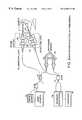
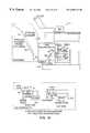
- FIG. 1is a block diagram of an embodiment of an OCT imaging system.
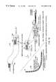
- FIG. 2is a block diagram of an embodiment of a Non-Retroreflected OCT configuration.
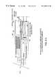
- FIG. 3is a block diagram of the modular system configuration.
- FIGS. 4 a-iare crossectional views of embodiments of a catheter with forward scanning capabilities.
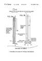
- FIGS. 5 a and 5 bare longitudinal sectional views of embodiments of devices which permit forward scanning by translation.
- FIGS. 6 a-fare longitudinal sectional views of embodiments of a catheter that utilizes a fixed lens and movable fiber for forward scanning.
- FIGS. 7 a-fare longitudinal sectional views of embodiments of a catheter that utilizes a fixed fiber and movable lens for forward scanning.
- FIGS. 8 a-dare crossectional views of general methods for deflecting imaging beam in a forward direction.
- FIGS. 9 a-care longitudinal sectional views of embodiments of imaging beam characteristics.
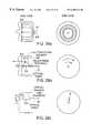
- FIG. 10is a longitudinal sectional view of an embodiment of a forward-scanning hand-held probe.
- FIG. 11is a longitudinal sectional view of an embodiment of a forward-scanning hand-held probe with inter-changeable magnifications.
- FIG. 12is a longitudinal sectional view of an embodiment of the integration of a hand-held probe with a surgical scalpel for image-guided surgery.
- FIG. 13is a longitudinal sectional view of an embodiment of a forward-scanning hand-held imaging/laser surgical probe.
- FIG. 14is a longitudinal sectional view of an embodiment of a forward-scanning laparoscope with relay/rod len(s).
- FIG. 15is a longitudinal sectional view of an embodiment of a forward-scanning laser surgical laparoscope.
- FIG. 16is a longitudinal sectional view of an embodiment of a surgical/dissecting microscope with multiple scan methods.
- FIG. 17is a longitudinal sectional view of an embodiment of a high numerical aperture OCT a microscope.
- FIGS. 18 a-bis a longitudinal sectional view of an embodiment of a flexible forward-directed optical guidewire/scanning endoscope.
- FIG. 19is a longitudinal sectional view and a cross-sectional view of an embodiment of the integration of forward-imaging devices with endoscope accessory ports.
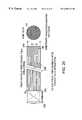
- FIG. 20is a longitudinal sectional view of an embodiment of a close-pack fiber bundle with cross-talk reduction.
- FIGS. 21 a-cis a longitudinal sectional view of an embodiment of an imaging surgical grinding catheter.
- FIG. 22is a longitudinal sectional view of an embodiment of the distal end of a device with an integrated microchip for image acquisition.
- FIGS. 23 a-bis a longitudinal sectional top and side view of an embodiment of optical phased array for forward imaging.
- FIG. 24is a frontal view of anatomical sites for implantable probes.
- FIGS. 25 a-dare longitudinal sectional views of embodiments of surgical tools and probes.
- FIGS. 26 a-cis a longitudinal sectional view of an embodiment of laparoscopic and endoscopic surgical tools/probes.
- FIG. 27is a longitudinal sectional view of an embodiment of a surgical biopsy punch tool.
- FIGS. 28 a-cis a longitudinal and cross-sectional view of embodiments of devices for cervical imaging.
- the imaging enginecan be of a variety of embodiments including optical coherence tomography or other interferometric imaging systems, fluorescence and other spectroscopic imaging systems, Raman imaging, diffuse wave optical imaging, two photon imaging systems or combinations thereof.
- the imaging engineincludes the associated imaging system sub-systems such as optics, electronics, motors, computers, and controls necessary to generate high resolution images, control image acquisition, and to process, quantitate, and display images, and manage databases.
- light from an optical source 10is directed to a given position on a specimen to be imaged, ranged, or otherwise measured via a probe module.
- Interferometric techniques 19can be used to collect and detect light altered by the internal microstructural features in the specimen in addition to the other techniques mentioned above.
- the interferometric imaging techniqueis often of an embodiment where the optical beam directed onto the specimen is spatially coherent, having a single-spatial mode, and thus the delivery system can be from a single-mode fiber.
- the detected lightis processed in a receiver processor 38 to extract information on the specimens optical properties as a function of depth or other spatial metrics (e.g. location of incident beam on the sample).
- a reflectivity profile, or plot of the sample reflectivity as a function of depthcan be obtained.
- the probe modulemay include methods for performing scanning of the radiation pattern.
- by performing repeated measurements while scanning the incident optical beam at a plurality of points on the specimen image informationcan be obtained.
- imagescan be acquired in parallel.
- OCT imaging enginesinclude: reference-arm scanning, frequency tunable optical source, and optical spectral analysis imaging.
- the interferometer 19 and associated opticsare used to couple light from the optical source onto the sample and optical reference.
- the interferometer 19also couples light after being altered by the sample and optical reference (either delayed, transmitted, reflected, or scattered) onto the receiver processing unit 38 in such a way that optical interference between the sample and reference light occurs and is detected and converted to electronic signal(s).
- the interferometermay contain free-space optics and/or optical fibers. In one embodiment the fibers are single-mode fibers.
- the interferometermay be of a variety of embodiments including Michelson or Mach-Zehnder configurations.
- frequency or phase modulation elementsenable en face imaging or enhanced signal processing; dispersion balancing and compensation elements maintain high longitudinal resolution; and polarization controllers, polarization-maintaining or single-polarization fiber, or polarization diversity techniques maintain good signal-to-noise ratio or provide information concerning the birefringence of the sample.
- Transverse (including lateral, axial, or radial) scansare acquired using the actuator to scan the optical radiation emitted from the probe unit into the sample and from the sample into the probe unit.
- depth (or longitudinal) scansare acquired using one of the three methods mentioned above and described below.
- the computercontrols the interaction between transverse and depth scanning to generate 1,2 or 3 dimensional images.
- the OCT imagesrepresent information on the microstructural optical properties of a sample. These include index-of-refraction discontinuities, scattering, absorption, birefringence, dispersion, and spectra-scopic properties of a sample.
- the propertiescan be spatially resolved using a variety of scanning techniques.
- Such techniquesinclude performing sequential depth scans interlaced with transverse scans or vise versa or the images can be acquired in parallel. Because rapid images can be obtained, the extensions beyond 1, 2, or 3-D imaging are possible with this invention. In particular, by visualizing images over time, functional imaging is possible. For example, the visualization of a beating embryo heart in response to various stimulants can be achieved.
- a mode-locked, superluminescent or other suitably broad-bandwidth optical sourceis used and coupled to the interferometer.
- reflectivity profiles of the samplecan be obtained.
- known methods for reference arm scanningincluding linear translators, galvanometers, fiber stretching, rotating elements (mirrors, cams, and glass blocks), and grating based delay line scanning. Only when the reflections from the sample and reference arm path lengths are equal to within the source coherence length is optical interference detected. Thus by scanning the reference arm path length, depth resolved interferometric profiles of the samples optical properties can be obtained.
- the receiver processing unit 38can consist of a single detector, dual-balanced detectors, or an array of photo-detectors followed by appropriate amplification and signal processing.
- a frequency tunable optical sourceis coupled to the interferometer.
- the receiver processing unit 38includes photo-detectors which receive signals from the sample and reference reflections and detects any optical interference. The slight time delay between the arrival of these two signals, combined with frequency tuning, results in a beat signal from which the reflectivity or other interferometric profile of the sample's optical properties can be derived using rf spectral analysis techniques.
- There are several methods for performing a wide frequency sweepincluding mechanically or electronically tuned external cavity lasers, current or temperature tuned semiconductor lasers, multi-section semiconductor lasers, and broad-band amplified spontaneous emission sources combined with tunable optical filters.
- the sourceis again a broad bandwidth source coupled to an interferometer. Reflections from the sample/specimen and reference reflection(s) will optically interfere at the receiver, which is an optical spectrum analyzer.
- the optical spectrumwill consist of fringe profiles, the contrast of which is proportional to the reflection coefficients within the sample and the period of which is proportional to the relative distance between the sample and the reference reflection(s).
- signal processing algorithmssuch as Fourier analysis the reflectivity or other interferometric profile of the optical properties of the sample can be obtained.
- There are a variety of known methods for performing spectral analysisincluding single or multiple gratings or prisms combined with scanning detector systems or array detectors and narrow-band tunable filters.
- the sourceis a Raman pumped master-oscillator power amplifier (MOPA) source.
- Raman amplifiersare commonly used in Wavelength Division Multiplexing (WDM) optical communications systems and their use can be extended to OCT sources.
- WDMWavelength Division Multiplexing
- Using a strong CW or pulsed pump laserone can create a broadband optical power amplifier at the Stokes shift away from the pump laser ( ⁇ 13 THz). If this amplifier is seeded with a lower power semiconductor, fiber, or other broadband master oscillator source then it will be amplified to a higher power.
- the bandwidth of the amplifierwill be broadened, approximately, by a factor of two. Additional pumps can be used to further broadened the amplifier bandwidth and the gain spectra associated with the individual pumps can be tailored to shape the gain spectra by tailoring their respective pump powers.
- the master oscillatorcan be tailored to be very broadband by using in-fiber Bragg or long period fiber gratings or using WDM multiplexing techniques.
- a Faraday isolatorcan be used between the master oscillator and the power amplifier to maintain good stability.
- the pump lasercan be derived from a cladding pumped Yb or Nd fiber or other rare earth doped fibers pumped from broad area or other semiconductor lasers as is known in the art. These lasers lase at ⁇ 1.1 ⁇ m and they can be used to pump Er:Yb fiber to create a Raman pump laser at a wavelength around 1.55 ⁇ m. This is suitable for generating an OCT Raman source at ⁇ 1.6 ⁇ m, or it can be used to create multiple Stokes shifted pumps using a series of in-fiber Bragg gratings to create a OCT Raman source around 1.3 ⁇ m.
- the optical source 10 usedis invisible to the human eye.
- a visible aiming laser 46that is co-aligned with the source.
- This co-alignmentcan be obtained using a dichroic multiplexer or other suitable beam combining techniques.
- This aiming lasercan be directly visualized by a human operator using a hand-held probe or surgical microscope or other embodiments of this invention.
- a special imaging cameracapable of detecting radiation unseen by the human eye, can be used to visualize the optical source radiation. Either the visible aiming laser or the imaging from the special camera can be used to feed the visualization sub-system described in the next section and is key to performing several diagnostic and therapeutic medical procedures.
- the optical source 10is coupled to a 2:2 fiber optic splitter 14 containing paths to a reference mirror 18 (corner cube) and to a probe unit 22 that illuminates the sample. Additional sources or aiming laser could be connected to unused coupler 14 (not shown).
- the beam waist of the illumination port 26 of the probe unit 22is offset from the beam waist of the receiver port 30 of the probe unit 22 by a three dimensional vector R and a two dimensional coordinate rotation ⁇ .
- the light from the receivor port 30is recombined with the light reflected from reference mirror 18 into a 50/50 optical combiner 34 to form signals that enter the receiver processor 38 whose output is analyzed by a computer 42 .
- the scanning of the two light fieldscan thus be independent.
- This information derived using the signal processingis now not a reflectogram but a measure of the time delay through the sample. Information on group delay, index of refraction, scattering, and absorption coefficient can be obtained. This embodiment can be readily integrated into the microscope and other devices described in the following sections.
- the OCT systemdoes not need to operate in retro-reflection mode which is implicitly or explicitly assumed in almost all prior art. Not only does this enable a new design alternative for OCT systems but it can enable extraction of new information. For example, in previous direct retro-reflected embodiments often a large surface reflection, at, for example, an air/skin interface, can mask all the weaker reflections from just below the surface; a condition known as a blindness limitation. By operating in non retro-reflection this surface reflection is eliminated. Scattering is dependent on angle. Thus by setting ⁇ 0 a new measurement of the sample's optical properties can be obtained.
- ⁇could be scanned to produce an image of the interferometric optical properties of the sample as a function of scattering angle.
- All three of the OCT imaging engine embodiments described above as well as other optical imaging techniquescan be used with this non-retroreflection feature.
- This non-retroreflection embodimentmay be realized using two single-mode fibers side-by-side or twin-core optical fiber.
- Diffuse-wave imagingis a fairly new optical imaging technology that uses the diffusion properties of highly scattered light to perform imaging. Diffuse-wave imaging has demonstrated clinical applications for functional monitoring such as for the determination of oxygenation.
- An interferometeris not required for diffuse-wave imaging.
- the sourceis often a sinusoidally intensity modulated laser and the receiver is a direct detection receiver that measures the relative intensity and phase of the detected light with respect to the transmitted light.
- the delivery systemneed not be a single-mode fiber and often a multi-mode fiber offers superior signal collection. Images of the specimens' optical properties can be obtained by plotting the phase or magnitude of the detected optical intensity as a function of scan location. As with the OCT imaging engine, the images are displayed and used for diagnosis or in guiding therapeutic procedures.
- Fluorescence based medical discrimination or imaging technologycan be successful in a number of clinical diagnostic applications. Fluorescence imaging is based on using short wavelength visible light to excite native fluorescence (or fluorescence from selectively bound exogenous chromophores) in tissues. Differences in the biochemical constituents of the tissue will produce differences in fluorescence spectra. These differences in spectra are typically assessed either at a set of discrete points across the optically accessible tissue surface or as an image of the tissue surface. Differences in fluorescence are then interpreted with an algorithm in order to differentiate the pathology of the tissue. Typically, the desired endpoint is to assess the presence of dysplasia or cancer.
- the sourcecould consists of a short wavelength excitation laser and the receiver would consist of optical spectrum analysis of one or more regions tuned to the fluorescence wavelength. As the incident excitation radiation and collected fluorescence radiation is scanned, optical images of the specimen are obtained, displayed, and used for diagnosis or in guiding therapeutic procedures.
- probe-module scanning designs and concepts described in this inventionare applicable to other imaging engines such as Raman, two-photon, multi-photon, confocal microscopes, etc.
- these probe-module scanning designscan be use as stand alone therapeutic devices without the aid of an embedded imaging technology.
- an OCT and fluorescence imaging enginecould be used simultaneously over the same single-mode probe module optics.
- the OCT source and the short wavelength excitation lasercould be combined using a fiber optic wavelength division multiplexer (WDM) coupler and the collected OCT light and fluorescence light could be separated using another WDM coupler.
- WDMfiber optic wavelength division multiplexer
- Simultaneous images of fluorescence and OCTcould be displayed.
- the probe modulecould contain two fibers, one single-mode fiber for OCT imaging and one single or multi-mode fiber for fluorescence imaging. Common or separate scanning elements could be used to direct the respective radiation patterns. As the two imaging technologies contain distinct information, improved decision making in diagnostic or therapeutic procedures would be obtained.
- the apparatus of one embodiment of this inventionprovides optical imaging by way of scanning an optical beam in linear, circular, and arbitrary patterns. Scanning is performed using a probe module of various designs coupled to an imaging system. From a systems perspective, the invention can be described in terms of: 1) Actuation techniques which translate, direct, or deflect the optical beam for the purpose of collecting data and obtaining an optical image; 2) A probe module which utilizes the actuation technique and which contains various optical components necessary to deliver the beam to or receive the beam from the specimen or sample to be imaged; 3) An imaging system to which the probe module is attached and contains the source of the light beam, detection electronics or instrumentation, means and methods for displaying the obtained image data, and all associated imaging sub-systems including optics, electronics, motors, controllers, and computers to control the incident light, detect the image signal, process the incoming data, and assemble the data to form a one, two, three, or four dimensional data set and image; 4) Implementation methods which combine all the elements of this invention in a user-friendly, beam deliverable device
- the Beam Delivery/Scanning Module 12which includes the general forward-scanning (or other types of scanning e.g. radial, lateral, or axial) methods which are described in detail herein. Various methods are used to scan or translate the optical beam in order for the system to collect data and form an image.
- These general forward-scanning methodsinclude any number of beam delivery or probe modules including, but not limited to hand-held probes, laparoscopes, surgical microscopes, high numerical aperture or standard microscopes, forward-scanning flexible catheters, fiber bundles, or phased arrays.
- the forward-scanning methodmay: be directly integrated with the existing optical system, as with the laparoscope and microscopes; function as an independent imaging device such as the hand-held probe; function as a flexible catheter; function as a phased array; or function as an attachment which inherently adds to the functionality of the research or clinical instrument or tool as in the hand-held probe attached to the surgical scalpel to perform image-guided surgery.
- An OCT Scanning Engine Module 11includes a light source, axial (depth or range) scanning, and detection sub-system. Just as the Beam Delivery/Scanning Module 12 represents a modular component with interchangeable devices, so too does the OCT Scanning Engine Block 11 .
- the three engines described abovepermit axial ranging to be performed within the optical system and components.
- the reference-arm scanning, source frequency scanning, and spectral analysis OCTall permit axial ranging, but perform this by distinctly different methods. Each of the three methods may be used in conjunction with any of the beam scanning methods.
- several other optical scanning enginescan be used including other interferometric imaging systems, fluorescence and other spectroscopic imaging systems, Raman imaging, diffuse wave optical imaging, two photon imaging systems or combinations thereof.
- the OCT Scanning Engine Module 11 and the Beam Delivery/Scanning Module 12are controlled by a Control Computer Module 13 typically including a central computer which is responsible for synchronization, generating drive waveforms, generating necessary trigger pulses, storing and recalling data, and any necessary signal and image processing.
- the control computermay also function as part of the last module, the Visualization Module, although this may be a separate entity.
- the Visualization Module 15receives the image data from the Control Computer Module 13 , OCT Scanning Engine Module 11 , and/or directly from the Beam Delivery/Scanning Module 12 . Visualization may be performed with an OCT image monitor and/or a standard video monitor and/or a CRT. Generally, three screens are required for complete visualization: 1) a screen containing all the system parameters and settings to control the operation of the system, 2) a screen containing the video image of the tissue about to be imaged with OCT, and 3) a screen containing the OCT image of the specimen/sample.
- the video imageis the en face surface view of the specimen, tissue, or sample, while the OCT image is a cross-sectional profile, en face, or other tomographic slice of the sub-surface morphology or structure.
- all screensmay be visualized simultaneously on one monitor or video technology can be applied to permit picture-in-picture displays with various windows being called up on demand. Additionally, the video technology can permit integration with heads-up display allowing the user to view these screens via a head-mounted or semi-transparent window. Virtual reality may be incorporated with the given data screens.
- Heads-up display conceptscan be integrated within the eyepieces of the microscopes allowing the user to visualize the OCT image and the cross-sectional, sub-surface morphology of the specimen without having to remove his/her eyes from the microscope and hence the specimen.
- Video technologymay also permit such images to be overlaid thereby permitting the OCT image to be superimposed or fused over the video image with proper registration and alignment.
- the visible aiming laser described previously 1can also be displayed in the Visualization Module 15 . This visible aiming beam can be displayed on the screen containing the video image to allow registration of the OCT and video images by the user.
- Such visualization techniqueswill permit other critical data such as retrieval of previously acquired images and access to patient records while the procedure is being performed.
- Such systemscan be readily integrated with existing computer networks and more powerful computers which would enable computationally-intensive tasks, such as three-dimensional display and manipulation to be performed off-site and downloaded to the user for visualization.
- the Therapeutic Engine Module 17is associated with medical, scientific, and industrial applications where image guided procedures are required. This module 17 uses the information output from the Visualization Module 15 to guide therapeutic procedures. This guidance can be through a human feedback aided by the Visualization Module 15 or autonomous via computer or other control mechanism in the Control Computer Module 13 or within the Therapeutic Engine Module 17 itself. Example applications where this imaging guide therapy would be beneficial include guidance of mechanical or laser-based atherectomy catheters, placing stents, inflating balloons using percutaneous angioplasty catheters, operating microsurgical tools during laparoscopy procedures, etc.
- Forward-directed optical scanningcan be performed via a number of methods. These methods are then incorporated into various instruments.
- the optical devicewill involve one or more optical fibers to deliver the light to the sample, focusing optics to focus the beam to the desired spot with a predetermined spot size and confocal parameter, and a means of translation to enable the acquisition of adjacent axial scans for the purpose of assembling a multi-dimensional image.
- Scanning methodscan be generally, categorized as one of five general principles: 1) methods which move the fiber/lens as a single unit, 2) methods which move a fiber with respect to a fixed lens, 3) methods which move a lens with respect to a fixed fiber, 4) methods which deflect the forward-directed beam after the beam has been emitted from the fiber and focusing optics, and 5) combinations thereof.
- FIGS. 4 a-fSeveral embodiments for moving the fiber/lens as a unit are shown in FIGS. 4 a-f .
- the forward-scanning optics and mechanicalsare contained within, but not limited to, a cylindrical enclosure 50 that is small in diameter ( ⁇ 1-10 mm) such as a catheter, endoscope or laparoscope.
- This enclosure 50may be rigid or flexible and readily integrated into the instruments discussed in later sections.
- the distal end of the enclosure 50consists of an optional transparent window 54 that permits the optical beam to be transmitted with little attenuation while protecting the optics and mechanics from fluids and contaminants. Such an enclosure allows easy cleaning and sterilization.
- Distal to the tip of the enclosurelies the optical imaging plane. In the case of a single-mode optical fiber delivery this image plane may be the plane where the optical beam is focused to a minimum spot size. This plane should fall within the region of interest for the sample or specimen.
- FIG. 4 adescribes an apparatus for mechanical translation of the fiber/lens unit.
- a single-mode fiber 58is fixed to a GRIN lens 62 or a small diameter lens such as a ball lens at a given separation. This separation specifies the working distance to the focal plane, the spot size, and hence, the confocal parameter.
- the lenscan be fabricated directly into the fiber forming a single focusing unit.
- the fiber/lens unitlies within a track (not shown) which permits the unit to slide back and forth in a linear translation.
- Mechanical translationis accomplished by a motor 61 and rotating shaft 66 . Affixed to the shaft is an elliptical knob 70 or cam which displaces the fiber/lens unit with each rotation.
- a spring-apparatus(not shown) returns the fiber/lens unit back to its original location when not displaced by the elliptical knob 70 .
- Rotation of the motor shaft 66translates the fiber/lens unit along its track while imaging is performed in the forward direction.
- the motor unit 61may also be located at the proximal end of the device with the rotational torque transferred to the distal end and the transverse displacement mechanism via a shaft or a torque cable encased in a rigid or flexible hollow housing.
- FIG. 4 btranslates the fiber/lens unit with a piezoelectric cantilever 74 .
- a cantilever 74bends when a voltage is applied across the cantilever materials. The applied voltage attempts to polarize the material with fixed dipoles. To align the dipoles, the material bends in response to the applied field. With the fiber/lens unit fixed to the cantilever 74 , bending results in a lateral translation of the unit. If the unit is rigidly affixed to the cantilever 74 , the translation is not truly transversely linear, but actually represents an arc. However, the deviation from a linear translation is negligible with respect to the translatable distance.
- Displacements of 1-2 mmis typical for bimorph cantilever 74 with 300 V applied. Displacements can also be increased by extending the arm of the cantilever 74 with a rigid tube. Displacements are increased linearly with increasing arm lengths. Other electromagnetic actuator means are also possible.
- the cantilever 78does not have to be made of piezoelectric material. Rather, piezoelectric stacks may be used in conjunction with a metal or flexible material cantilever.
- the cantilever 78would be flat to prevent twisting and thin in the axis of flexure to facilitate bending.
- By fixing one end of the cantilever 78 to the fixed points (housing) 76 and placing the piezoelectric stack 80 under the cantileversmall stack displacements can be mapped into large transverse displacements of the cantilever. Displacements can be increased by progressively locating the piezoelectric stack closer to the cantilever site of attachment.
- a piezoelectric stack to displace a cantilevercan be extended to two dimensions as shown in FIG. 4 h .
- a second cantilever 78 ′is mounted on the first and oriented with its flexion axis perpendicular to the first and driven by another PCT 80 ′.
- the cantileverspiezoelectric or otherwise
- the cantileversmay be oriented transverse to the axis of the device as shown in FIG. 4 i .
- the horizontal PZT 80 ′deflects off fixed point 76 causing motion of the fiber/lens attachment horizontally and deflection of the vertical PZT flexes the fiber vertically.
- This designalso, permits two-dimension transverse scanning in the forward direction.
- the actuators used to move the cantileversare not restricted to piezoelectrics, but may be magnetic, pneumatic, or other drives.
- one or more movable wires or guides 90are used to mechanically displace in a push/pull manner the fiber/lens unit in an arc about a pivot point 94 .
- the movable wire 90is housed within the cylindrical enclosure along with the single-mode optical fiber 58 .
- the translation of the fiber/lens unit 63is dependent on the point of attachment of the wire 90 with respect to the pivot point 94 . If the wire 90 is attached close to the pivot point 94 , then small movements of the wire 90 will result in large arc displacements of the fiber/lens unit 63 .
- Such a designmay suffer from bending of the cylindrical enclosure 50 if such a mechanism is employed in a flexible enclosure.
- FIG. 4 dutilizes pneumatic principles to displace the fiber/lens unit 63 within the enclosure.
- two or more air/fluid-filled bags 96 , 96 ′are used in a complementary fashion to hold the fiber/lens unit 63 and displace it in a transverse direction.
- linear translationwill result. If more than two bags 96 , 96 ′ are used, that transverse displacement can approach that of an arbitrary scan pattern.
- the number of bags 96 , 96 ′will probably be limited to two or four. Four bags will permit transverse scanning in two, orthogonal directions.
- a rigid tube 100can house the fiber 58 and lens 63 as shown in FIG. 4 e .
- a translation track 104is located near the distal end of the enclosure. This track is offset at an angle with respect to the axis of the cylindrical enclosure 50 .
- tensionis applied at the proximal end 102 of the rigid tube 100 , this tension causes the fiber/lens unit 63 to be translated at an angle, as well as in the transverse direction.
- Such a scan methodresults in an angled image plane. Imaging however, is still largely performed in the forward-direction. An angled image plane is equivalent to using one of the previous methods where the enclosure is tilted at an angle with respect to the sample.
- This angled image planecan be compensated for by internally altering the angle of the track and the direction which the rigid tube projects through the cylindrical enclosure.
- a small spring mechanismcan be added between the wall of the unit and the fiber/lens unit 63 .
- FIG. 4 fillustrates how electrostatic/magnetic principles can be applied to laterally translating the fiber/lens unit.
- the lens 63is coated with a metalized material which can be attracted to appropriately charged/magnetized contacts.
- electrostatically charged plates 108can be used to translate the fiber/lens unit 63 .
- the metalized lens 63will be attracted to this region and hence, be displaced in the lateral direction.
- the metalized fiber/lens 63 unitis attached to a flexural pivot (not shown).
- Very high lateral velocitiescan be achieved by rapidly alternating the charges on the plates and by translating the fiber/lens 63 unit at a natural or modified resonant frequency. By transversely displacing the fiber/lens 63 at its resonant frequency, displacement becomes more sinusoidal rather than linear. However, data acquisition rates and image display can be compensated for this non-linear translation.
- FIGS. 5 a, bA second concept which involves the movement of the fiber/lens unit is illustrated in FIGS. 5 a, b .
- the fiber/lens unit 63is fixed within the forward-imaging device, but the entire device is translated in the transverse direction to obtain the cross-sectional image. While the device is stationary, single axial scans of the same location are repeatedly acquired. When the device is translated, this motion is sensed by a sensing mechanism which instructs the control computer at which position to place the axial scan within the image. If multiple axial scans are acquired at the same location, these scans can be averaged or summed as determined by the user. Two sensing mechanisms are shown in FIGS. 5 a, b . The sensing mechanism in FIG.
- the sensing mechanism shown in FIG. 5 bis a position sensing rolling mechanism 125 analogous to the computer mouse. The device is physically placed on the specimen or sample to be imaged and translated across the surface. Motion, direction, and velocity are recorded by the position-sensitive rollers 124 and is used to assemble acquired axial scans.
- FIGS. 6 a-fillustrate these principles.
- the fundamental displacement mechanismswere described above and in FIG. 4 .
- a flat or angle-cleaved optical fiber 58is located on the translation mechanism.
- the fiber 58is then translated on one side (in the image plane) of the lens 62 .
- a translation of the focal region on the opposite side of the lens (in the object plane)results. Magnification or demagnification of the fiber face and the transverse displacement occurs with this design based on the separations between the fiber face, specimen, and the lens.
- This magnificationwill vary the spot size (transverse resolution) and the confocal parameter (depth of focus) of the device which differs from the fixed parameters described in the previous methods.
- the focal regionwill not lie in a single image plane, but will sweep out an arc.
- the focal spot sizewill change.
- a lens systemcan be manufactured which reduces the aberrations which result from this method of imaging.
- FIGS. 7 a - 7 fthe similar methods of translation are used to move the lens 62 in front of a fixed flat or angle-cleaved fiber 58 .
- the fundamental displacement mechanismswere described above and in FIG. 4 .
- translation of the lens 62 or fiber 58will result in the same difficulties such as aberrations at the beginning/end of translation and an arced, non-flat imaging plane but these can be overcome with known optical design techniques.
- FIGS. 8 a-dFour methods are shown in FIGS. 8 a-d for deflecting or re-directing the optical beam in the forward-direction for the purpose of imaging.
- FIG. 8 autilizes a rotating cable 128 within the cylindrical enclosure 50 .
- the optical fiber 58is contained within and is protected by the cable 128 .
- an offset GRIN lens 62(or other type of lens) is metered with respect to the optical fiber 58 . Because the lens axis is offset with respect to the optical fiber 58 , the emitted beam is not focused on axis with the fiber. Instead, the focus occurs at an angle which is dependent on the degree of offset between the GRIN 62 and fiber 58 .
- the cable/fiber/GRIN lens 128 , 58 , 62is rotated by a drive unit 60 .
- Drive unit 60may be implemented in a number of ways including mechanical linkage from a motor to a rotating torgue cable. As the unit rotates, a conical profile is traced out. Images acquired with this method represent a cone sample which can still be displayed in a 2-D manner similar to ultrasound.
- This forward-directed scanning methodhas the advantage that the device can be incorporated into flexible instruments or catheters.
- the lenscan be mounted on-axis with the fiber and the fiber/lens combination can be slightly tilted with respect to the axis of rotation.
- a second methodillustrated in FIG. 8 b , describes a technique for arbitrary scan patterns in the forward direction.
- This methodalso utilizes an internal cable 128 and an additional internal sheath 132 which rotate in counter-directions with respect to one another.
- the outer cylindrical enclosure 50remains fixed.
- the most inner elementis a metal cable 128 which houses and protects an optical fiber 58 within its core.
- the distal end of thisincludes a circular prism 136 (trapezoidal in cross section).
- External to this cable/fiber/prism 128 , 58 , 136is a counter-rotating sheath 132 that has a second prism 144 attached at the distal end.
- the emitted beamis focused by a lens 152 prior to exiting the cylindrical enclosure 50 .
- a lens 152prior to exiting the cylindrical enclosure 50 .
- an alternate embodiment(not shown) is to have one drive cable and a small gearing mechanism for counter driving the second prism.
- the lenscan be rigidly mounted to the fiber prior to transmission through the prisms or two lens could be used (not shown), before (to collimate) and after (to focus) the rotating prisms. This approach can yield better stability of the optical system.
- FIG. 8 cillustrates the use of a beam-deflector element 148 placed between a pair of lenses 153 , 153 ′.
- the proximal lens 153directs the light from the fiber 58 through the beam-deflector element 148 .
- a second lens 153 ′is used to focus the light into the image plane.
- the beam-deflecting elementcan consist of, but is not limited to, liquid-crystal, electro-optic, or acousto-optic modulators. Note that alternative embodiments can use different lens arrangements depending on the aperture size and type of beam-deflector used.
- the design illustrated in FIG. 6 dutilizes a two-dimensional miniaturized deflector 146 such as an electrostatic deflector that can be microfabricated on semiconductor or other substrates such as silicon mem's.
- the imaging beam exiting the fiberis reflected by a prism/mirror 150 on to the electrostatic deflector where it is redirected, reflected off of the other side of the prism, and then focused in the forward direction by a lens 153 .
- This designhas the potential for arbitrary scan patterns generated at high speeds.
- Other types of deflectorssuch as electromagnetic, piezoelectric, etc., can be use as well in this configuration.
- beam deflectioncan be accomplished by translating or displacing a mirror in front of the imaging beam using any of the actuators (PZT, magnetic, electrostatic, pneumatic) described in FIGS. 4-8.
- All of the described forward-scanning mechanismscan be generalized to side-directed linear scanning or side-directed radial scanning simply by the addition of a fold prism or fold mirror (not shown) to direct the imaging beam at arbitrary angles from the axis of the device.
- Side-directed linear scanningcan be performed by using a fold mirror and an electrostatic, mechanical, or other similar mechanism to rapidly move the device along the central axis of the device.
- Side-directed radial scanningcan be performed by using a fold mirror and rotating the device about the central axis using a electrical motor or magnetic mechanism.
- eachcan be modified by duplicating transverse displacement components to scan in two-dimensions (x/y).
- x/yBy controlling the scan pattern along each axis, arbitrary scan patterns can be achieved and three-dimensional data sets can be acquired.
- FIG. 9Three key terms need to be introduced for future descriptions of imaging beam characteristics and are illustrated in FIG. 9 .
- the firstis called FOCUS POSITIONING (FIG. 9A) which is the axial displacement/adjustment of the beam focus without changing any of the beam parameters (focal spot size diameter, depth-of-focus, working distance).
- the secondis FOCUS VARYING (FIG. 9 b ) which implies changes in spot size, depth of focus, and working distance
- FOCUS TRACKINGFIG. 9 c
- the output optical beam characteristicswere fixed and independent of the transverse displacement.
- a fixed focal spot and positionwas transversely translated through the sample or specimen.
- a means of varying the separation between the fiber and the lenscan be implemented which will serve to vary the imaging beam characteristics and hence, perform focus varying. This could be accomplished by using a cylindrical piezoelectric stack, mechanical displacements with small motorized positioners, inflatable balloons, or pneumatic/hydraulic devices.
- the beam spot sizecould be increased or decreased (hence the transverse resolution varied), as well as the confocal parameter or depth-of-field.
- Such implementationpermits rapid imaging at lower resolutions and larger depths-of-field and later high resolution imaging at selected regions of interest.
- One methodinvolves translating the entire apparatus in the z (depth) direction either toward or away from the specimen. This repositions the focus appropriately. Translation can be performed manually with a micrometer adjustment or via a electrical/mechanical drive mechanism.
- a telescope configurationis used with a collimated beam between two lenses ( 156 , 156 ′) (for example as shown in FIG. 9 a )
- the separation between the two lenses 156 , 156 ′can be varied without affecting the beam characteristics.
- Such a telescopic arrangementis important for several implementations including endoscopes where it is desirable to be able to automatically adjust the focus positioning to compensate for varying distances to the luminal wall.
- Focus varyingcan be implemented to reduce the spot size (increase resolution) and hence, reduce the depth-of-field. At this point, focus positioning would be necessary to move the focus to a precise location in the specimen at a certain distance from the end of the imaging device.
- Focus varyingis illustrated in FIG. 9 b .
- lens 156is translated and changes spot size, depth field, and working distances.
- zoom lens configurationsSeveral alternative embodiments are possible such as zoom lens configurations.
- FIG. 9Cillustrates an example of focus tracking.
- ⁇ Lis the displacement of the focusing lens 156 ′
- ⁇ Fis the displacement of the focusing spot within the specimen 164
- ⁇ Ris the displacement of the optical path length of the reference mirror 160 (assumed to be in air) required to maintain the optical path length to the focusing spot within the specimen 164 equal to the optical path length to the reference reflection.
- ⁇ L, ⁇ F, and ⁇ Rcan be a complicated non-linear equation depending on the index of refraction profile within the specimen 164 and the numerical aperture of the lens 156 ′. This equation can be solved and programmed into the computer controller subsystem to achieve very high lateral and longitudinal imaging with the specimen 164 .
- the index profile of the sampleis approximately uniform and given by n sample , and small angle approximations to the focused light can be made (e.g. sin ⁇ ) then ⁇ F ⁇ n sample ⁇ L, and ⁇ R ⁇ (n sample ) 2 ⁇ L for the moving lens 156 ′ configuration shown in FIG. 9 c .
- the sample 164is moved toward a fixed lens 156 ′ (as might be implemented in a microscope stage described herein, then ⁇ R ⁇ ((n sample ) 2 ⁇ 1) ⁇ L.
- This equationalso describes the situation where the reference mirror base is attached to the moving focusing lens and adjusted relative to the focusing lens base.
- the tolerance that the focus tracking must achieve over the scanning range within the sampleis approximately equal to the depth-of-focus of the focusing lens. In many instances this simple approximation is sufficient to achieve the required result. In situations where very high numerical aperture lenses are used the more exact expressions or algorithms must be programmed into the computer controller subsystem to maintain focus tracking.
- the liquid volumewill adjust to maintain a constant focal point relative to the pupil of the focusing lens 156 ′.
- Another approach for focus trackingthat can easily accommodate more complex sample index profiles is to perform transverse priority scanning and adjust the reference mirror location to maximize image quality. This works well if the optical path length variation to the focus within the sample is less than the depth-of-focus.
- the adjustmentcan be manual in response to a human operator visualizing the real-time OCT image or it can be automated by maximizing the detected signal power averaged across the transverse scan or by maximizing other detected parameters.
- ⁇ L, ⁇ F, and ⁇ Rit may be possible to manually or in an automated way derive the relationship between ⁇ L, ⁇ F, and ⁇ R.
- one algorithmnis to block the reference optical signal and use the OCT system in a direct detection confocal microscope.
- a highly reflecting substratee.g. a mirror
- the operatorfirst locates the specimen's front surface reflection by bringing the sample into the field-of-view and searching for the first maximum in detected signal power.
- the specimenis then scanned manually or in an automated way to profile the back scattered signal power in search for the weaker reflection off of the more distant mirror.
- the two positions for the focusing lens (or samples translation stage)are recorded.
- the focusing lensis then placed at the front surface reflection.
- the OCT systemis placed into its interferometric mode and the reference reflection optical path length is scanned and the position of maximum interferometric signal is recorded. This locates the focusing lens and reference arm path length to the front surface reflection.
- the focusing lensis then placed at the back surface (mirror) reflection and the OCT reference reflection optical path length is again scanned and the position of maximum interferometric signal is again recorded. This locates the focusing lens and reference arm path length to the back surface reflection.
- An approximate (linearized) relationship between ⁇ R and ⁇ Lcan be found by the difference in the reference mirror locations divided by the difference in the focusing lens locations. This linearized approximation will be sufficient for many specimens of interest.
- this algorithmcan be extended by searching for the samples back surface reflection (that is the mirror substrate reflection) in an iterative fashion in the coherent detection mode.
- the lens locationis stepped and the reference arm is swept and this process is repeated until the mirror location is identified. Knowing the samples approximate index and thickness can greatly reduce the search time and increase the reliability of finding the back surface location.
- Several other algorithms, that are extensions of these basis concepts, for manual or automated calibration of the focus tracking algorithmcan also be used.
- the general methods of forward-directed scanningcan be implemented in a hand-held device 164 that performs forward-directed optical imaging of biological specimens or material samples.
- the ability to have forward-directed imaging in an instrument having a size that can be conveniently hand held no larger than a penoffers the advantages of data and image acquisition at locations remote to the OCT computer control and imaging engines. This is largely due to the fiber-optic and micro-optic technology utilized by this invention. Contained within the hand-held probe 164 is all the translation mechanics, microoptics, and fiber-optic interconnect necessary for transverse displacement and forward-directed scanning.
- a hand-held probehas applications in, but is not confined to, the medical field, materials investigation, and the military.
- the medical fieldcan utilize its compact profile in the open-field surgical setting to image sub-surface tissue morphology prior to disrupting, incising, or resecting the tissue.
- a forward-directed imaging probeoffers the advantage that no portion of the instrument has to come in contact with the tissue prior to obtaining imaging data. This is in contrast to devices that image in the radial or transverse direction. Here, the catheter or device must be inserted into the tissue prior to obtaining an image. Within the open-surgical field, space is at a premium. Therefore, an additional instrument must be compact and easily manipulated by the surgeon.
- the hand-held probecan be used to access any external region of the human body, or any external orifice, without have the patient be placed in uncomfortable positions.
- the fiber path lengths between the sample and reference armsmust be matched or otherwise compensated for dispersion balancing. Because long fiber lengths can be contained within small volumes, the sample arm of the OCT imaging engine, to which is connected the hand-held probe, can be of any reasonable length. Therefore, a hand-held probe can be used to image any external region of the human body while the patient stands, sits, or lies in a bed.
- the distal portion of the devicecan be made very small and able to be inserted short distances into body orifices and canals such as the external ear canal, nasal passage, or mouth.
- FIG. 10One implementation of a forward-scanning hand-held probe is shown in FIG. 10 .
- This designutilizes a piezoelectric cantilever 74 to displace the fiber/lens unit 63 in an arc, however, the design is not limited to the use of cantilevers and may incorporate any of the general methods described herein.
- the overall dimensions of this deviceare no larger than a standard ink pen, making the instrument fit comfortably in the operator's hand.
- the cylindrical enclosure 50is made of a protective and insulating plastic that shields the cantilever 74 , fiber 58 , and lens 62 from contaminants and liquids.
- the use of an insulating plastic materialalso prevents injury to the user as a result of shorting between the voltage applied to the piezoelectric cantilever 74 and the user's hand.
- the piezoelectric bimorph materialis centered within the cylindrical enclosure 50 probe barrel to allow bending displacement during scanning.
- the proximal end 79 of the cantilever 74is fixed to a micrometer 168 to vary the location of the imaging beam focus with respect to the distal end of the probe and with respect to the tissue specimen or sample.
- a tube 172is fixed at the end of the cantilever 74 . This increases the distance of the fiber/lens unit 63 from the bending cantilever 74 and linearly increases the displacement.
- the tubealso protects the small lens 62 and single-mode fiber 58 .
- the lens 62 used in this designis a GRIN (GRadient INdex) lens which allows effective focusing of the light emitted from the fiber while maintaining a small outer diameter.
- the small cylindrical GRIN lens 62easily fits within the cylindrical tube 172 .
- the fibercan be angle-cleaved and the GRIN can be angle-polished.
- the fiberis attached to the GRIN lens using ultraviolet cured optical cement at a pre-determined distance. This distance determines the focusing properties of the emitted light such as working distance, spot size, and confocal parameter.
- Alternate lens embodimentsinclude using fiber up-tapers with an integrated polished lens or other lenses that are known in the art.
- the distal end of the cylindrical enclosurehas a clear plastic cap 176 that is removable after contact with biological tissue.
- This capserves four major purposes: 1) to allow the probe to be placed in contact with the tissue specimen or material sample thereby fixing the image plane at a fixed distance within the specimen, 2) on contact, motion artifacts are minimized because the probe can move with the tissue or sample, 3) the clear plastic permits the user to visualize where scanning is occurring when a visible aiming beam is coincident with the OCT imaging beam, and 4) the replaceable cap maintains cleanliness and avoids transmission of bacteria or viruses between patients.
- the only interconnections required with the use of this designinclude the single optical fiber and two wires 174 , 174 ′ necessary to drive the piezoelectric cantilever. Typically, voltages of several hundred volts are necessary to displace the cantilever 1 mm.
- the use of the extension arm 172increases the displacement to 2 mm. Larger displacements can be achieved by increasing the applied voltage (while remaining below the damage threshold of the material) and increasing the length of the extension arm.
- FIG. 11A second hand-held probe design is illustrated in FIG. 11 .
- This designutilizes similar cantilever-displacement principles, but offers an interchangeable lens 180 to vary the magnification of the device. Instead of affixing a GRIN lens to the fiber, the fiber 58 alone is attached to the cantilever 74 and displaced at the focus of a fixed lens 152 .
- This designis not limited to the use of piezoelectric cantilevers, but may utilize any method which produces suitable x and y displacement of the fiber in the focal plane.
- the light emitted from the cleaved fiber 184is collimated by lens 152 and directed toward a second, more distal lens 180 where it is focused at a forward imaging plane, within the sample to be imaged.
- Other imaging systemsmay also be used.
- the distal cap 176 and lens 180are interchangeable by replacing unit 190 or 176 thereby permitting various magnifications and scan lengths to be obtained.
- the interchangeable cap 176 and lens 180are disposable and serves to protect the remainder of the probe from liquids and contaminants.
- This designhas different optical properties than the scanning fiber/lens design in FIG. 10 .
- the previous designhas resolution and depth of field determined by a fixed fiber/lens separation with transverse translation determined directly by displacement.
- the micrometer 168 represented in FIG. 11is only one means to adjust the separation between the fiber 58 and the proximal lens 152 and other techniques can be incorporated. Because of the magnification factor associated with the two lenses, the displacement of the fiber tip via the micrometer or other technique does not result in a 1:1 mapping of the displacement of the focus within the sample.
- the use of the hand-held probe 164 in the surgical settingoffers simple integration with existing surgical devices such as a scalpel 186 as is shown in FIG. 12 .
- the forward-directed imaging probe 164is comparable in size to a surgical scalpel 186
- the twocan be attached in a manner to permit forward-directed imaging to be performed prior to incision with the scalpel and at arbitrary angles with respect to the surgical blade.
- Two-dimensional imagingcan be integrated or multiple image planes can be imaged simultaneously by interweaving the scan pattern or by using two translation modules. These two or more planes can be simultaneously displayed. Images obtained with the imaging probe will permit the surgeon to view the sub-structure and avoid sensitive structures such as nerves or vessels or assist in determining locations of tumors and identifying tumor margins prior to resection.
- OCTmay be configured to perform laser Doppler velocimetry of the tissue prior to incision.
- Imagescan be generated which detect and display any sub-surface movement, such as flowing blood, which would indicate the presence of an artery or vein.
- the scalpel bladecould be rotated 90° with respect to the axis of imaging, and the probe could be located below the scalpel so that the cutting axis is imaged prior to incision.
- one or more optical fiberscan be positioned within the scalpel blade itself (for example in a blade made of optically translucent material or in a more conventional metal blade with appropriate imaging ports) (not shown) with the tip of the fiber located at the tip or along the edge of the scalpel blade.
- imagingcan be performed whereas with lower numbers of fibers, isolated depth information can be acquired.
- Single axial scanscan be performed which can provide depth ranging information of the tissue prior to scalpel blade insertion. If the fibers are in near contact with the specimen or sample, the lenses to focus the light may be low power or may not be needed at all.
- Such fibersmay be located within a blunt-tipped probe (see FIG.
- the blunt probeis typically held in the opposite hand as the scalpel and frequently used to point to and identify tissue.
- the coincident visible aiming beam and the use of sub-surface imaging with the probewill extend its application in the surgical environment.
- an entire micro-scanning devicecan be incorporated onto the end of the scalpel which scans the beam in an angular pattern along the incision plane.
- the use of a coincident visible aiming beampermits the user to visualize the location of the infrared or invisible imaging beam. This feature allows precise placement and alignment of the imaging beam on the sample or specimen.
- high power continuous wave lasers or high energy pulsed laserscan be integrated with the OCT imaging system to replace the surgeons scalpel.
- These conceptshave been demonstrated in the past as workable means of thermally incising, coagulating, or mechanically disrupting biological tissues.
- High power or high energy laser lightcan effectively be delivered with single-mode or multi-mode optical fibers.
- FIG. 13illustrates the concept of integrating both a single-mode optical fiber 58 for OCT imaging with a single- or multi-mode fiber 59 for tissue incision or disruption.
- Each fiber 58 , 59could be translated with a piezoelectric cantilever 74 , 74 ′ either synchronized or independently.
- each of the fibers 58 , 59could be attached to the same piezoelectric cantilever 74 , 74 ′ or the surgical laser fiber 59 could remain stationary and the OCT system would scan through and about the point of surgical incision.
- Both the OCT imaging beam and the high power/energy laser radiationmay be propagated down the same optical fiber permitting precise registration between OCT image and location of laser surgical procedures.
- This designwill enable a single, integrated hand-held device which utilizes OCT imaging as a guide for laser surgery. This configuration also permits the acquisition of images prior to, during, and immediately following the delivery of the laser power/energy to immediately confirm the location and extent of the damage.
- wavelength selective beam splitters/couplers(not shown) or fast optical switches (not shown) could be used to combine/separate the two light sources.
- the fine control of the lasercould be controlled from the optical image by the therapeutic interface described in reference to FIG. 3 .
- FIGS. 10-13The designs discussed and shown for the hand-held probe (FIGS. 10-13) all utilized the general forward-scanning method of a piezoelectric cantilever. As shown in FIGS. 4-8, other methods are possible which permit the forward-directed scanning in a compact, portable, and potentially remote hand-held instrument for optical imaging.
- a small pair of orthogonal galvanometers(not shown) can also be incorporated at the proximal end of the hand-held probe to direct the imaging beam off of rotating mirrors. This design will permit rapid two- and three-dimensional scanning as well.
- the internal scanning mechanismcan be configured to rotate about the axis of the instrument. This would permit linear scanning at arbitrary angles. Multiple axes can be incorporated to allow two- and three-dimensional scanning.
- the design of the forward-scanning hand-held proberepresents a general method of transverse displacement that is modular in design. Using the probe to transversely displace a focus in a forward-imaging plane is useful in other optical instruments such as a rigid endoscope or laparoscope.
- a laparoscopeis an optical device that is used typically in medical applications to visualize tissue surfaces with magnification at a remote internal site. The concept of laparoscopic surgery has contributed to minimally invasive surgery; the idea that surgical procedures can be performed without large incisions and without exposing internal tissues during an open-field surgical procedure. As shown in FIG. 14, the laparoscope 192 consists of a rigid cylindrical enclosure 50 1-2 cm in diameter and 10-50 cm in length.
- the proximal end 200contains optics that permit the operator to visualize the tissue surface located at the distal end 204 .
- a CCD camera 194can be mounted at the proximal end 200 with the en face image of the tissue appearing on a video monitor (not shown).
- Optics contained within the laparoscope 192relay the image of the tissue in the object plane to an image plane at the proximal end 200 .
- white-light fiber-optic bundles( 198 ) that run parallel to the imaging optics which provide illumination of the tissue surface.
- Typical surgical procedures using laparoscopesinvolve inflating the human abdominal cavity with a gas to provide space to visualize internal organs and to manipulate various surgical instruments within the cavity.
- FIG. 14illustrates the optical design of a forward-scanning laparoscope. At the proximal end 200 are optics which permit the simultaneous en face viewing and OCT imaging utilizing the same optics along the length of the laparoscope. A transverse scanning mechanism (not shown) is employed based on either those described in FIGS.
- proximally located scanning elementscan be extended to two dimensions and permit arbitrary scan patterns at the distal end 204 of the laparoscope. This arbitrary pattern can be observed and controlled by the operator through the laparoscope via the coincident visible aiming beam.
- the CCD imaging camera 194can display the scan location, pattern, and direction.
- a transversely scanned beamis focused by a lens 152 and fully reflected by a beam splitter 14 which transmits visible wavelengths, but reflects near infrared wavelengths.
- the OCT imaging beamis focused at the image plane of the laparoscope relay optics 202 .
- the relay optics 202consists of either a series of GRIN or relay lenses or a single GRIN rod lens, or other type of lens as is known in the art. In either arrangement, the result is a relay of the image plane to the object plane located distal to the end of the laparoscope. Hence, translations of the OCT beam focus in the image plane are relayed as translations in the object plane where the tissue sample is located.
- an alternative to transverse scanningis to locate a angular scanning device(s) in a pupil plan at the distal end of the laparoscope.
- Rod lensesare typically defined by their pitch length. An integral pitch length rod lens will relay a non-inverted image from one face to the other. In this case, a beam which is focused into the proximal end of the rod lens will be focused at the distal end as if the rod was of zero length. For rod lenses that are of n/2 path lengths, where n is an odd integer, the image at the opposite rod face will be inverted.
- the systemresembles a focusing lens plus additional distances and hence, constructs an image at image/object planes located given distances away from the faces of the rod lens.
- these non-integral pitch length rod lensesare used in conjunction with additional focusing/collimating lenses.
- These lensescan be small standard lenses, ball lens, or additional GRIN lenses which can be attached directly to the rod lens.
- the magnification of the lens/rod lens of the laparoscopesets the resolution and depth-of-field as well as the magnification of the displacement of the scanned beam.
- techniques of focus varyingcan be performed by adjusting the separation between various optical components and hence varying the magnification.
- Focus positioningcan be performed by displacing a distal focusing lens in the axial direction if the beam exiting the rod lens is collimated.
- an eyepiece lens 151is used to image the image plane, through the beam splitter 14 , on to either the human eye or a CCD 194 camera.
- White-light illuminationis delivered through multi-mode fibers 198 located radially around the relay optics 202 .
- the difference in wavelengths between the OCT imaging beam (e.g. 1300 nm) and the visible wavelengths ( ⁇ 650 ⁇ m) when passed through the same relay optics 202results in non-coincident image/object planes. This, however, can be compensated for by adjusting the location of the eyepiece 151 and focusing lens 152 located at the proximal end.
- each wavelengthcan effectively be relayed down the laparoscope 192 to a single coplanar object plane.
- a chromatic optical element(s)can be used in the common path to maintain a common image plane.
- one modificationincludes the addition of a second beamsplitter 14 ′ to allow the high-energy/power light to enter the relay optics 202 and be delivered to the distal end and the tissue.
- the focal lengths of the eyepiece 151 and image beam focusing lens 152are lengthened.
- An alternate designmaintains the locations of the proximal optics but replaces one of the white-light fiber bundles 198 ′ with the multi-mode fiber which will deliver the high-energy/power light.
- Alternate optical embodiments that provide for the visualization, transverse scanning, and high power laser portscan be used as is known in the art.
- non-scanning OCT or other optical imaging technologiessuch as parallel detection using an area-imager, can be used in this laparoscope application in place of a transverse scanning approach shown.
- yet another embodimenthas the surgical laser integrated into the OCT imaging port.
- the surgical lasercan be integrated via a WDM coupler (or other means) to deliver the surgical light to the exact spot being imaged.
- This integrated laparoscope designwill combine the ability to visualize intra-abdominal contents or other internal body structures via minimally invasive surgical procedures with sub-surface OCT imaging of architectural morphology and the ability to thermally or mechanically disrupt tissue using laser surgery.
- Forward-directed scanningcan be integrated with existing surgical or dissecting microscopes to permit imaging of an arbitrarily oriented sub-surface tomographic plane to be performed simultaneously with en face visualization.
- Dissecting or stereo microscopesare typically binocular microscopes with long working distances (low numerical aperture (NA)) and large confocal parameters. They are frequently used in the research environment for low magnification of large samples that cannot be placed on the stage of a high-magnification, high NA microscope.
- Surgical microscopes with long working distances and long depths-of-fieldsare utilized in microsurgical techniques to enable the surgeon to visualize small structures such as arteries, veins, tendons, and nerves. Use of these microscopes is critical during procedures involving the reattachment of severed hands, feet, and limbs as well as the reconstruction of delicate structures around the face, head, and neck.
- the en face view, along with a visible aiming beam coincident with the near infrared imaging beam,can be captured and stored on either video tape or digitized and stored on computer storage media.
- FIG. 16The concept of the forward-scanning surgical microscope 210 is illustrated in FIG. 16 .
- Three scan methodsare shown.
- the optical fiber 57 from the sample arm of the OCT imaging engineis inserted into a collimator 67 .
- the collimated beamis directed through a pair of galvanometer scanners 206 before passing through a focusing lens 152 .
- the orthogonal scannersenable the forward-directed imaging beam to be scanned in arbitrary patterns on the specimen or sample. This arbitrary pattern also enables the acquisition of multiple cross-sectional planes for 3-D image acquisition.
- a beamsplitter 14 mounted at 45°redirects the near infrared imaging beam and the visible aiming beam downward and coincident with the field of view of the microscope optics.
- the beam splitter 14is coated to reflect the imaging and aiming beam wavelengths while allowing other visible wavelengths to transmit.
- the focusing lens 152will focus the imaging and aiming beams at two different locations. Since the visible aiming beam is only used to trace the location of the imaging beam, its focal position is relatively insignificant.
- FIG. 16 bA second method for forward-scanning is shown in FIG. 16 b .
- This conceptreiterates the modularity of the forward-scanning instruments.
- the methods previouslycan be used to perform forward-directing scanning beneath a surgical/dissecting microscope.
- the cylindrical enclosure 50 or probe 164can be attached to the scope 210 to place the forward imaging plane on the sample which is positioned for viewing by the microscope 210 .
- One of the advantages of this methodis arbitrary positioning of the probe 164 around the microscope 210 with quick removal for hand-held operation. To avoid the field-of-view of the microscope 210 , however, the probe 164 can be positioned at an angle with respect to the imaging axis of the microscope 210 .
- the cross-sectional image obtained with the imaging probe 164will not be in the same orientation as the en face view.
- the probe 164can be placed within 10-20° of the microscope axis if the dimensions of the probe 164 are minimized.
- a fold mirror(not shown), similar to the beamsplitter in FIG. 16 a can be used to allow a freely held probe to be positioned horizontally to access the specimen from along the microscope visual axis. Linear scans at arbitrary angles can be obtained by rotating the forward-directed imaging probe 164 about its axis.
- the stage 217 and/or and imaging probe 164can be rotated about a fixed point on the specimen to provide various angles for imaging.
- two-dimensional scanningcan be performed by incorporating multi-axis cantilevers or other two-dimensional displacement mechanisms.
- the confocal parameter of this deviceis large, focus varying and focus positioning can be incorporated to improve the flexibility of the device and its ease-of-use when integrated with the microscope 210 .
- a visible aiming lasercould be included in the probe unit 164 to easily facilitate registration of the en face microscope view and the OCT image.
- the visible aiming lightwould enable the operator to visualize where the scan of the sample is being made.
- the microscopecan be designed with a small monitor 167 to allow the OCT image to be seen directly through the eyepiece 218 so a surgeon/operator may remove the probe 164 and freely move it about the sample while observing the scan along the surface via the visible aiming beam and see the tomographic projection below the surface via the OCT image in the eyepiece 218 .
- the hand-held probe 164may contain a therapeutic device such as discussed with respect to FIGS. 12 and 13.
- FIG. 16 cAn alternative to the modular probe concept which permits cross-sectional imaging along the same axis of the microscope 210 is shown in FIG. 16 c .
- This designutilizes the piezoelectric cantilever 74 described in earlier sections.
- the cantilever 74is attached to a translation stage 214 so that flexure of the cantilever 74 results in an arc swept out in the direction orthogonal to the stage 214 translation.
- a fiber/GRIN lens unit 63is attached so the optical imaging beam is directed downward toward specimen. This unit can be positioned beneath the imaging optics of the microscope.
- a second stage(not shown)can be used to position the focus at given depths within a specimen.
- the focusis swept in an arc through the specimen.
- the translation stage 214can be used to acquire multiple arcs and construct a 3-D data set. Positioning this design beneath a stereo-microscope does limit the view of the sample or specimen to be imaged. However, the profile of the cantilever 74 and GRIN lens 63 can be made very thin and if placed far enough away from the focus of the microscope imaging optics, then the cantilever 74 will not be distracting to the user.
- the cross-sectional image obtained with the OCT or other type of imaging enginecan be overlaid or otherwise combined so that a human user can simultaneously view both images through the eye piece(s) 218 or by other means.
- Forward-directed imaging methodscan be integrated with a high numerical aperture (NA) microscope.
- NAnumerical aperture
- These microscopesare commonly used for research laboratory investigation of biological specimens as well as small, microscopic, material samples. Magnifications in these microscopes are higher than in the surgical/dissecting microscopes, typically between 50-400 ⁇ . High magnifications imply short confocal parameters or depths-of-field for the microscope objectives.
- the numerical apertures for these objectivesis higher ranging from 0.1 to 0.5 and higher.
- the principle advantage of integrating forward-directed optical imaging techniques with a high NA microscopeis to allow the precise positioning of the imaging beam on the specimen or sample, particularly when the specimen is on the microscopic scale (100-1000 ⁇ m).
- Focus trackingpermits the coherence envelope of the OCT source to be continuously aligned with the focal region of the microscope objective and hence, collect image information only within the confocal parameter (the region of highest and relatively constant transverse resolution).
- the focus depth in the specimenis not simply related to any mechanical tracking parameter.
- custom generated waveformswill be generated to focus track inside a specimen.
- a high speed dynamic feedback systemcan be used to compensate as imaging is performed.
- FIG. 17illustrates the integration of forward-directed imaging with a high NA microscope 222 .
- Commercial microscopeshave been designed to provide several access ports which can be utilized for forward-directed OCT imaging.
- Typical portsinclude the camera port 226 used for CCD 194 or 35 mm cameras (not shown), the port 226 ′ designed for direct illumination, and access to the optical path via the objective mount 230 .
- the microscope implementation in FIG. 17 ademonstrates a CCD camera 194 attached to the camera port 226 , a galvanometer scanning mechanism 206 to scan the imaging beam through the direct illumination port 226 ′.
- a galvanometer-based scanning mechanism 206 ′ in an objective mount 230which is inserted into the optical path of the microscope, prior to the microscope objective 234 .
- the sample to be imagedis placed on the stage 214 of the microscope 222 .
- the stage 214is raised or lowered to position the focus of the imaging beam within the sample as well as to focus the image for visualization through the eyepieces 218 .
- a monitorcould also be added analogous to 167 in FIG. 16 .
- the optical fiber 57 from the sample arm of the OCT imaging engineis attached to a connectorized fiber collimator 238 which collimates the imaging beam before being reflected off a pair of orthogonal galvanometer mirrors 206 .
- the orthogonal galvanometers 206allow arbitrary scan patterns at the object plane of the microscope 222 as well as for acquiring multiple image planes for 3-D data set acquisition.
- the collimated beampasses through the illumination port 226 ′ and enters the optical path of the microscope by way of a beamsplitter 14 designed to reflect both the OCT imaging beam and the visible aiming beam while transmitting all other visible wavelengths.
- the collimated imaging beamis focused by an infinity-corrected microscope objective 234 which is anti-reflection coated for the wavelength of the imaging beam.
- the advantage of this implementationis the inconspicuous location of the forward-scanning device and its access via previously incorporated microscope ports. A limitation of this design is evident if direct illumination is desired. In this case, multiple illumination ports must be incorporated into the microscope design.
- the second implementation shown in FIG. 17utilizes micro-galvanometer scanners 206 ′, or other forward-directed scanning methods (such as those described in FIGS. 4-8) in a similar configuration as described for FIG. 17 .
- the entire unitis compact and small enough to insert between the microscope objective and the objective mount.
- This implementationalso incorporates a beam splitter 14 ′ designed to reflect the imaging and the aiming beams.
- a negative lens 158can be placed within the optical path of the microscope to correct for the additional separation due to the insertion of the scanning mechanism housing.
- the advantage of this implementationis the ease of access for a wide variety of microscopes and the rapid installation prior to use. In both implementations, because the imaging wavelength is out of the visible spectrum, specially coated optics and objective lenses are required. These, however, should not be any more expensive than existing high-quality objectives available today.
- scanningis performed with depth priority. That is, the beam is positioned at one location via a two-dimensional scanning mechanism while the OCT engine varies the effective path length between the sample and reference arms of the interferometer in order to collect data in depth (z direction). The scanning mechanism then repositions the beam and another axial depth scan is performed. Imaging can also be performed with transverse priority by keeping the axial position fixed during a single transverse scan and then stepping in depth as subsequent transverse scans are acquired. In a three-dimensional mode, this is equivalent to the optical sectioning characteristics of a confocal microscope.
- the advantage of transverse priority scanningis a potential increase in speed and simpler focus tracking implementation hardware and software.
- Rapid transverse scanningcan readily be performed with galvanometers and mirrors.
- the focus, as in focus tracking, or the axial position,cannot be varied as quickly.
- high rates of transverse scanningcan be performed if only a single fiber is displaced. If the fiber is attached to additional lenses or components, high speeds is more difficult due to the inertia of the lenses.
- the OCT imaging embodimentcan be extended to include non-retroreflected imaging embodiments as described with respect to FIG. 2 .
- the illuminationcould be scanned from above the sample and the detection light could be scanned as shown in FIG. 17 or could be scanned by other means such as locating the detection port below the sample stage.
- the illumination patterncould be stationary and only the detection port scanned.
- a flexible endoscope(a type of laparoscope) can be use to image in non-vascular tissue and a flexible catheter or guidewire can be used for intravascular imaging.
- the concept of forward-scanningcan be extended to devices such as these designed to access remote sites that are inaccessible with straight, rigid, optical instruments such as the hand-held probe and the rigid laparoscope. Such sites include internal body lumens or cavities that have narrow and tortuous paths of access.
- internal examination of pipes or tubing with bends or anglesrequires a forward-looking, flexible imaging device.
- inspectorsare often required to image sites that are located in tight, confined spaces or that lie “around corners”.
- FIG. 18One design for a forward-scanning flexible endoscope, catheter, or guidewire is illustrated in FIG. 18 .
- Performing optical imaging in the forward direction through a flexible endoscope, catheter, or guidewireincorporates new concepts.
- Housed within the flexible endoscope, catheter, or guidewire sheathare two imaging techniques which are used to provide both an en face and cross-sectional view of the specimen or sample.
- the first imaging technique contained within the flexible endoscope 250 , catheter or sheathis designed for en face imaging and is performed through a sealed transparent tip 254 located at the distal end 254 of the device.
- a fiber bundle and lens combination 258is used both for white-light illumination and en face viewing of the specimen.
- This imaging techniqueis used to guide the endoscope 250 , catheter, or guidewire through the tortuous path to the site to be imaged with OCT. Once at the site, this fiber bundle 258 is used to visualize where OCT imaging is being performed by observing where the visible scanning beam is located.
- the second imaging technique contained within the sheathis designed for OCT or other laser-based optical imaging of the specimen.
- Contained within an inner, second sheath 262is a rotating metal or rigid-material cable 266 .
- a metal pin 270is located at the distal end of the cable and is displaced from the center of the cable axis. This metal pin 270 inserts into a groove 274 at the base of a pivoting GRIN, ball, or small lens housing 280 .
- the GRIN lens 62is located at the distal end of the housing 280 , over the site where the housing pivots.
- a single-mode fiber 58runs parallel to the sheath 262 and cable 266 and inserts into the GRIN lens housing 280 where it is fixed to the GRIN lens 62 at a given distance.
- the fiber 58may run inside the speedometer cable with appropriate sheathing to protect it (not shown).
- the fiber/lens separation and the lens characteristicsdetermine the beam focusing properties of the endoscope, catheter, or guidewire and can be varied as in focus varying techniques.
- the GRIN lens housing 280is free to pivot about an axis located at the GRIN lens 62 .
- the rotationis translated to the distal end to drive the GRIN lens housing 280 .
- the displaced, rotating pin 270 on the cable 266which is inserted into the groove 274 of the GRIN lens housing 280 , causes the GRIN lens housing 280 to pivot back and forth.
- the pin and groovethat influence the resulting scan pattern.
- the appropriately shaped elliptical grovewill achieve a linear sweep of the forward-scanning light.
- Alternative groove designsmay be circular and implement sinusoidal forward scanning of the emitted light from the endoscope.
- the linear (transverse) scanning of the forward-directed lightis preferred since the dwell time (and hence signal-to-noise) on each transverse pixel is constant.
- One method to achieve thisis to have the cable 266 rotated at the proximal end 256 at a constant angular velocity.
- the off-axis metal pin 270from the perspective of the GRIN lens housing 280 , is translated in one plane in a sinusoidal manner.
- Multi-dimensional data setscan be acquired by rotating the entire endoscope 250 , catheter, or guidewire within the lumen or cavity and collecting multiple pie-shaped cross-sections about a single central axis.
- Forward-directed optical image datacan be acquired without transverse displacement by using a flexible, forward-directed optical guidewire 284 shown in FIG. 18 b .
- a single-mode optical fiber 58is located within the core of a metal guidewire or guidewire 284 made of other material. The distal end of the fiber 58 has some means of focusing the light into the specimen either by a molded, integrated, fiber lens or an attached micro-GRIN lens (not shown).
- This devicepermits collection of a single axial scan as the guidewire 284 is inserted into the lumen or cavity.
- Guidewiresare used in nearly every catheter-based procedure to define the path of the catheter through the lumen. Often, the procedure is performed without visualizing via ultrasound or x-ray where the tip of the guidewire is located.
- the insertion of the guidewireis extremely critical when approaching sensitive tissue such as thin lumen walls or atherosclerotic plaques which are prone to rupture or dislodge and cause a potentially fatal thrombotic or embolic event.
- sensitive tissuesuch as thin lumen walls or atherosclerotic plaques which are prone to rupture or dislodge and cause a potentially fatal thrombotic or embolic event.
- the single axial ranging datacan provide information regarding the tissue type and structural morphology distal to the end of the guidewire and reduce the likelihood of forcing the guidewire through sensitive areas.
- outer diametersrange from 1-3 mm for the flexible forward-scanning endoscope, catheter, or guidewire down to several hundred microns for the optical guidewire. These outer diameters permit the device to be inserted into the accessory ports 268 of current flexible endoscopes or catheters or guidewires as illustrated in FIG. 19 in longitudinal and cross-sectional views of the distal end.
- OCT or laser-based imagingcan be improved by utilizing the various additional ports for irrigation, micro-manipulation, and white-light illumination already implemented in the clinical instruments.
- Forward-directed imaging using a flexible fiber bundle 288is another embodiment of this invention and is shown in FIG. 20 .
- the flexible bundle 288is composed of a large number of close-packed single-mode optical fibers 58 .
- the orientation of the individual fibers at the proximal 292 and distal 294 ends of the bundleare maintained which implies that a scan pattern at the proximal end 292 is accurately represented at the distal end 294 of the bundle.
- a previous attempt to perform forward-directed imaging through a fiber bundle using low-coherence interferometryresulted in moderate to significant inter-fiber mode coupling which increased the transverse point-spread-function. This effect would lower the transverse resolution of the image.
- a highly absorbing materialis inserted into the bundle 288 to surround each individual fiber 58 .
- One possible materialis a liquid suspension of carbon particles; or each individual fiber can be coated during the fiber manufacturing process.
- An alternative approach and/or complementary approach to using the cross-talk reduction materialis to use signal processing algorithms. If the degree of mode-coupling is known or is predictable, image processing routines can be used to remove the artifacts induced by the cross-coupling.
- a microscope objective or high numerical aperture lens 296is used to focus the OCT imaging beam on to the proximal face 292 and to individually and sequentially address in time each fiber 58 .
- the propagating lightis focused at the object plane, distal to the end of the bundle, by an integrated fiber lens (not shown). Fiber lenses integrated into each fiber eliminate the need for additional, larger focusing lenses at the distal end and eliminate the aberrations induced with this type of optical setup.
- microlens arrays or a bulk optical lens group similar to that used at the proximal facecould be used to relay and magnify or de-magnify the image.
- Transverse translationis accomplished at the proximal end 292 by placing either the microscope objective of the proximal end 292 of the bundle on a translation stage (not shown) that has sufficient resolution and precision to address each individual fiber 58 or by using a combination of angle scanning devices and lenses.
- a direct parallel detection of the imagecan be utilized.
- the flexible-endoscopecan be integrated to guide or autonomously control laser and other surgical devices.
- a single or multi-mode optical fibercould be integrated into the center of the imaging bundle.
- the overall diameter of the fiber bundleis on the order of 1-2 mm.
- Such a small, flexible deviceis ideal for integration in endoscope accessory ports or used independently for vascular access of small arteries and veins.
- Atherectomy and grinding catheters and endoscopeshave been designed and used to remove tissue or material at a remote site or close to highly sensitive structures. Many of these designs are small and integrated into rigid probes or flexible catheters. Typical applications include rigid forward or side-directed removal of vitreal strands at the vitreal/retinal interface and the forward and side-directed removal of atherosclerotic plaques within the human coronary arteries. In the first example, visualization is poor because of the small, nearly transparent structures that are being removed. In the second example, visualization is nearly impossible because of the location of the catheter within the blood-filled human coronary arteries. Because visualization is critical for distinguishing between normal and abnormal tissue, forward-directed imaging methods can be integrated with forward and radial-directed rotating blade/grinding catheters in order to image the tissue prior to grinding and removal.
- FIG. 21 a ishows the distal end 304 of a radial-directed rotating blade catheter 300 with additional imaging optics.
- the catheter 300 used for this procedureis flexible and of small diameter ( ⁇ 3 mm).
- the distal end 304has a region of the outer sheath 308 removed to expose the rotating blades 312 . This is the region where grinding or tissue removal occurs.
- a rotating shaft 316which is used to rotate the blade 312 at the distal end 304 .
- the curved, rotating blades 312also provide a mirror-like surface off of which the OCT imaging beam is reflected.
- the area of the blade 312 where the imaging beam is incidentcan be physically isolated from the grinding region in applications where the accumulation of contaminants or the deposition of blood which would decrease the reflectivity of the surface.
- One or a pair of single-mode optical fibers 58run along the length of the catheter sheath 308 . Each is attached to a focusing element 320 which focuses the beam at the object plane located outside of the catheter sheath 308 in the region to be removed by the rotating blades 312 .
- the bladesare machined at a precise angle and pitch (e.g. a helix) so that as the blade rotates in front of the beam, the reflected beam is directed to a different location along the imaging plane.
- the imaging planemay not necessarily be a single line and hence a straight cross-section.
- This cross-sectioncan provide useful information about the tissue morphology and composition prior to removal by the rotating blades.
- the device used in FIG. 21could be used solely for diagnostics. That is the device could be completely sealed (eliminating problems with debris clouding the field of view) and the rotating helical blades used simply for performing lateral imaging.
- an imaging port 324could be located within the rotating shaft 316 .
- the optical fiber 58could run along or within the axis of the rotating shaft 316 and a small beam director 328 (e.g. GRIN lens attached to a small prism) could be used to direct light to the specimen.
- a small beam director 328e.g. GRIN lens attached to a small prism
- the essential design featureis that the rotation used to drive the cutting blade is used to simultaneously drive and scan the optical radiation pattern.
- Multiple imaging ports(not shown) could also be used.
- the optical imaging portcould be designed so as to allow automated or manual adjustment of the location of the beam director element along the axis of the rotating shaft as shown by arrow in FIG. 18 a ii.
- the imaging optics in the beam directorwould be arranged to achieve a circular spot of the appropriate diameter and confocal parameter as is known in the art and indicated. In some applications it is desirable to cover a wider area while sacrificing resolution. For instance, if the primary goal is simply to perform ranging to the closest feature to the tissue wall, one possible enhancement to the optical design is to use a cylindrical lens to widen the footprint of the beam along the axis of the rotating shaft as indicated.
- FIG. 21 bA forward-directed rotating blade with forward-directed imaging is shown in FIG. 21 b .
- the conceptsare similar to those described above except here the distal face 304 of the catheter 300 is open and is the site of tissue removal.
- Three forward-imaging conceptsare illustrated.
- FIG. 21 b ivarious forward-directed scanning mechanisms can be implemented as was shown in FIGS. 4-8. Imaging is performed through the rotating blades 312 with the imaging plane located distal to the end 304 of the catheter 300 . If the pitch of the rotating blades 312 is small, the duty cycle for imaging will be large. There will only be brief periods when imaging cannot be performed because the blade 312 is in the beam path. Acquisition can also be gated to only occur when the blade 312 is out of the beam path.
- 21 b .iiuses a single focusing element 320 and relies on the curvature or pitch of the blades 312 to reflect the imaging beam. As the blades 312 rotate, the focus of the beam is translated across the imaging plane and is used to acquire a cross-sectional image of the tissue prior to removal. As stated above, this type of deflecting technique can be used solely for diagnostics.
- an imaging port 324could be located within the distal portion of the rotation shaft 316 .
- a small spinning beam director 328can be used to sweep out a conical section in front of the rotating grinding region.
- the spinning shaft which drives the multi-tine bladeis also used to scan the optical radiation pattern.
- FIG. 21 c ishows another embodiment of a forward grinding catheter/endoscope 300 .
- an optically clear block 332 with an integral grinding surfaceis rotated.
- the OCT or other laser imaging systemis used to image through the grinding element 332 and into the tissue/specimen of interest.
- only part 336 of the forward surface of the grinder 332is open to interface with the tissue.
- Alternate designscan convert the circular motion of the rotating shaft 316 to a gearing mechanism that rotates the clear grinding block 332 whose spinning axis is rotated 90° with respect to the block shown in FIG. 21 C.
- an optical beam director elementcould be located offset from the axis of rotation but within or attached to the spinning grinding block 332 itself.
- the offset radius and the emission angle with respect to the axis of rotationcan be tailored for the application of interest.
- the concept in FIG. 21 c ii of a spinning element with a grinding surface and an internal or external optical imaging portcan be extended to include a transverse grinder as well.
- One of the central concepts of this aspect of the inventionis the use of the mechanical motion of rotational or reciprocal cutting tools to also drive the optical imaging port which can be coupled physically with the cutting tool so that motion of the cutting tool is used to simultaneously perform scanning thereby maintaining registration of the cutting tool surface and the image field of view.
- the distal end of the probe or devicewas used primarily for scanning, beam delivery, and collection.
- OCT imagingWith the ever increasing ability to micro-fabricate electrical and optical components on silicon or semiconductor substrates, it will be possible to perform optical or OCT imaging with a single microchip located at the distal end of a probe or flexible catheter.
- the catheter sheath or cylindrical enclosureconsists of a distal transparent window 340 and is only a few millimeters in diameter.
- the connections between the integrated microchip 344 and the remaining instrumentationconsists of only a few electrical wires 174 for control, input, and output of data.
- micro-fabricated componentsfor the light sources, interferometers, beam focusing optics, beam directing or scanning, light detection, and detection, filtering, and signal processing electronics. Interferometer arm path length changes are performed with micro-mechanical components or with non-mechanical means as described previously for the OCT imaging engines. Although illustrated in a small, forward-facing chip in FIG. 22, the integrated components could occupy the entire distal end 348 of the flexible catheter or probe.
- Input to the microchip 344include power, control for source output, wavelength, tuning, etc., as well as parameters for image scan length and beam focusing characteristics. Output from the chip includes any feedback signals for control and the data stream used to display the image.
- phase arrayshave the advantage that they contain no moving parts and thus can be scanned quickly. They rely on the precise relative optical phase of the emitted light from each array element which either constructively or destructively interferes with the emitted light from other array elements. By modulating the phase between individual elements, it is possible to arbitrarily position the location of the constructive interference (and hence, the focal spot) in a defined region surrounding the array.
- phased arraysThere are a variety of types of phased arrays that are known and regularly used in RF radar and communication devices.
- OEICopto-electric integrated circuit
- This OEIC 352contains one or a series of beam dividers (not shown) which split the optical signal into N channels.
- the OEIC 352may be made of silica on silicon (SiO 2 /Si), LiNbO 3 , InGaAsP, or other elements commonly used for creating optical waveguides and/or phase shifting elements.
- Each of the N channelscontains an electro-optic or thermo-optic phase shifter 356 .
- This phase shifter 356may be on the same optical substrate as the beam divider waveguides or on a separate element optimized for phase shifting.
- phase shifters 356By controlling the relative phase in between elements, arbitrary illumination patterns can be obtained. In particular if a time varying linear phase shift is implemented in between elements, the beam will be scanned off-axis as shown. The relative spacing between elements of the phase shifters 356 and the number of elements determine the amount of angle that can be scanned over and the far-field pattern. Note that a one-dimensional scanning pattern would require cylindrical or anamorphic optics to achieve the appropriate depth-of-field and scan pattern in the sample as shown. Note that semiconductor or solid-state optical amplifiers could be integrated onto the phased array to reduce the effect of absorption and splitting losses in the OEIC.
- phased arrayis to utilize multiple (e.g. 100) individual fibers arranged in either a linear format or as a two-dimensional array. Focusing optics may not be required for the array although beam conditioning optics may be necessary to optimize the performance of the array and to reduce the focal region of the array.
- the proximal end of the devicemust include piezoelectric or mechanical fiber stretchers which vary the length and/or rotate each fiber (and hence change the phase of the light) by several hundred microns, or enough to sufficiently vary the phase by 360°.
- the imaging enginesince this requires beams to be propagated down each fiber as well as back-scattered light to be detected, the imaging engine must perform all of these operations in parallel. We note that this approach to control the phase in individual fibers despite catheter bending and fiber stretching must be done precisely.
- Important components of this inventioninclude designs and applications in connection with guiding or assessing the effects of therapeutic instruments which disrupt or remove tissue via abrasion, compression, blade excision, heat, shockwaves, or laser light.
- This guidanceincludes procedures which destroy tissue (as opposed to removing it from the site) such as applying RF, laser, or toxin additions to the site.
- Some of these designshave already been illustrated (e.g. FIGS. 12, 13 , and 21 ). Others are straight forward extensions of the designs and methods already illustrated. This section will present some examples of methods and designs for additional diagnostic and therapeutic applications of this invention.
- One embodiment of this inventionis the concept of implantable or embeddable probes (or other devices) in living biological tissues or other structures/specimens such as a structural composite to allow continuous or periodic extraction information on the tissue or specimen that otherwise would be inaccessible or difficult to obtain.
- These probescould be implanted during a surgical procedure and left permanently attached or removed at some distant time point in the future when the concern of disease is eliminated or reduced to an acceptable level, or in other situations where the implant is no longer needed.
- An example of using implantable probesis shown in FIG. 24 .
- the implanted fibersmay consist of a single fiber or fiber bundles and they may work in retro-reflection mode, transillumination mode, or any relative location of transmitters and receivers as described with respect to FIG. 2 .
- the number of transmission fibersmay be different from the number of receiver fibers.
- the receiver processing unitcan have a mechanical switch to address the separate detection required of each individual receiver fiber or multiple receivers may be used or the fibers may be wavelength or time division multiplexed. Multiple fibers can have any orientation with respect to one another around the tissue of interest so as to optimize the detection of salient features necessary for diagnosis of disease state, structural integrity, or other parameters.
- the interface between the OCT system and implanted probesmay be present within the body (for instance a small distance below the surface of the skin such that transcutaneous illumination is possible) or outside the body (for instance a small fiber optic connector is secured to the external surface of the body).
- the implanted devicecan be used to monitor the effect of radiation, chemicalibiological toxin, or other therapeutic procedures as illustrated in FIG. 24 .
- Fibers oriented around and/or within the tissue of interestcan be used to detect structural and/or metabolic changes indicative of response or toxicity of the agent of interest. This diagnostic information can be used in real-time to coordinate the therapeutic procedure or in non-real time where the effects of the therapeutic agent are gathered over a long period of time and continuously or periodically assessed to guide further treatment.
- the implanted devicemay be used to assess neural activity.
- Fiber(s)may be placed in direct contact or in close proximity of either peripheral or central myelinated or unmyelinated nerves.
- Neural activitymay be monitored by either changes in nerve size, spectral properties (absorption, polarization, etc.), or response to exogenous probe.
- chemical concentrationsmay be measured in organ parenchyma (such as the myocardium), lumen (such as the urinary tract or blood), support structures (such as fascia), or free space (such as in lungs or other cavities) via the direct placement of single or multiple fibers.
- organ parenchymasuch as the myocardium
- lumensuch as the urinary tract or blood
- support structuressuch as fascia
- free spacesuch as in lungs or other cavities
- the implanted devicemay be used to assess regional or whole body vascular function.
- Probesfor example, may be placed in both external cerebral and lower extremity vessels (combine with or without Doppler imaging ability) to assess changes in relative blood flow during postural changes or high G maneuvers associated with air flight.
- the implantable devicemay be implanted within and/or in the general vicinity of the bone marrow for the purpose of monitoring the production of both normal and abnormal blood cells.
- the implanted devicemay be placed in the organ of interest for the assessment, with or without the addition of other biological probes, of phenotypic changes such as cell size, cell number, muscle strain/contraction, nuclear concentration, or cell surface maker concentration.
- the devicewill be placed within or in the vicinity of the lung for the purpose of assessing regional lung function such as changes in alveolar size or local gas concentrations.
- Forward directed imagingcan be performed with the source fiber or fibers proximal to the tissue of interest and the receiving fiber/detector distal to the tissue of interest. This is a special case of the concepts previously described with respect to FIG. 2 .
- the procedurewould be of particular use for assessing or surgically manipulating vessels, nerves, and lymph nodes.
- the illumination beam and/or receiver aperturecan be scanned with any of the previously described methods.
- the receiving elementcan consist of a single fiber or detector (aperture scanned or not) or a fiber or detector array could be used and demodulated as described above.
- a single housing(open on three sides) could allow the probe/device to be placed in the tissue of interest while allowing rigid metering between source and detector planes.
- Forward, axial, or cross-sectional directed imagingcan be performed during transurethral prostatectomy procedures such as: transurethral resection of the prostate (TURP), suprapubic prostatectomy, transurethral incision of the prostate (TUIP), transurethral laser incision of the prostate (TULIP), visual laser ablation (VLAP), and open prostate surgery. Guiding the prostatectomy procedure with OCT and other optical imaging modalities and devices of this invention can dramatically improve patient outcome.
- one or more fiberscan be placed within, adjacent, or on the struts of the retractable blades (similar to that discussed with respect to FIG. 12 ). Fibers will extend to sites from the distal to proximal end of the blade.
- a flush portmay be included on the guide catheter surface adjacent to the blade for the purpose of flushing blood and/or tissue debris.
- the high power laser lightcan be coupled into the OCT fiber (via time or wavelength division multiplexing techniques as described previously) or to an adjacent fiber as described with respect to FIG. 13 .
- Forward directed backscattering or transillumination imagingcan be used with instruments used in the surgical field including scissors, forceps, hemostats, and snares. Uses will include preventing iatrogenic injury, assessing/guiding nerve and vascular repair, and open field tissue diagnostics.
- the probescould be used for one-dimensional ranging and thus do not require scanning or could be of any of the scanning embodiments described previously.
- FIG. 25shows some examples.
- FIG. 25 ashows a simple hand held surgical probe 340 that could be used in a wide variety of general purpose medical procedures and fields.
- a fiber 57runs down the center of the surgical probe 340 and contains the imaging and scanning optics 346 as a simple lens such as GRIN lens 62 (or no lens) at the distal end 344 .
- FIG. 25 bshows an example of medical scissors or hemostat device 348 .
- the optical imaging and scanning module 346is mounted near the hinge 352 and aligned so as to illuminate the region near where the tip of the two blades 356 meet upon closing.
- FIG. 25 ashows a simple hand held surgical probe 340 that could be used in a wide variety of general purpose medical procedures and fields.
- a fiber 57runs down the center of the surgical probe 340 and contains the imaging and scanning optics 346 as a simple lens such as GRIN lens 62 (or no lens) at the distal end 344 .
- FIG. 25 bshows an example
- FIG. 25 cshows a similar example of forceps 358 with the optical imaging and scanning module 346 mounted so as to illuminate the region between the tips of the two forcep prongs 360 .
- FIG. 25 dshows an example where the optical imaging and scanning module 346 is used to illuminate the region near the end of a snare 364 .
- the integration with the OCT or other optical imaging enginecan include single or multiple fibers and utilize the wide variety of scanning techniques described earlier or can use simple 1D (longitudinally only) scanning to minimize the cost and complexity of the probe module.
- Forward-directed backscattering or transillumination imagingalso can be used with instruments used in laparoscopy/endoscopy including scissors, forceps, snares, or dissecting probes similar to those described with respect to FIG. 25 and shown in FIG. 26 .
- Devices used in laparoscopic and endoscopic procedureshave a much longer rigid shaft 368 to allow the medical specialist to perform the required procedures through small incisions which are distant from the location of interest. Due to the minimally invasive nature of these devices it is preferable that the imaging and scanning optics be located within the long smooth body of the tool as opposed to outside the body of the device as in FIG. 25 .
- the devicescan have a simple single fiber 57 for performing longitudinal ranging and 1-D imaging, can contain a fiber bundle (not shown) for multi-dimensional imaging, or contain a small scanning mechanism at the distal end 344 for multi-dimensional imaging as described previously. Uses will include preventing iatrogenic injury, assessing/guiding nerve and vascular repair, and tissue diagnostics.
- the integration with the OCT systemcan include single or multiple fibers.
- Punch biopsies of tissuecan be guided with the use of forward, lateral, or cross-sectional OCT and other optical imaging techniques as described in this invention.
- punch biopsy toolstypically consist of small (1-5 mm diameter) cylindrical blades 372 at the distal end 344 that cut a core of tissue that is retained in the bore of the cylindrical blade 372 .
- Optical fibers and beam focusing opticscan be located within the cylindrical blade or, in the case of excisional grippers (pinchers) (not shown), can be located at the pivot-point of the instrument similar to what is shown for scissors in FIG. 25 b .
- Obtaining punch biopsies at remote sites within the bodyis extremely difficult if not guided by some imaging technology.
- the use of forward-directed OCT or other optical imaging techniqueswill permit sub-surface imaging and identification of tissue and tissue morphology prior to extraction and reduce the high error rates and morbidity associated with random or unguided sampling.
- Tissue extraction or disruption(performed with rotating spurs, blades, or similar devices, compression, heat, shockwave, RF, toxin, or laser illumination) can be guided with forward, lateral, or cross-sectional OCT or other optical imaging techniques, devices, and methods of this invention.
- Single fibers or fiber bundlesmay be used to perform ranging or imaging as required.
- Tissue extraction or disruptionmay be performed in an antegrade or retrograde direction.
- extraction or disruptioncan be performed in a cross-sectional direction or parallel to the axis of the catheter/endoscope.
- Tissue extraction or disruptionmay be guided with feedback from the OCT system, thereby changing, for example, regional blade speed or pressure or in the event that several spinning or cutting mechanisms are used simultaneously (for instance along the shaft); the devices can be individually controlled by separate OCT imaging engines.
- FIG. 25 ain side and end view provides an example where imaging is accomplished using a fiber bundle 288 that is arranged in a series of one or more symmetric rings of fibers at the distal end as shown.
- Each fibercan be coupled (not shown) to a small lens, an integral fiber up-taper, or a single lens group.
- the fibers 57can be scanned sequentially using a free space beam steering mirror and lenses, coupled to a fast 1:N fiber optic switch matrix, or coupled to separate imaging engines (not shown).
- Shown in FIG. 28 bis a radial/circular scanning embodiment similar to that previously described with respect to FIG. 18 c .
- the output of fiber 57is collinated using lens 152 and reflected off mirror 154 and adjustable fold mirror 158 .
- the radial distance or angle of fold mirror 158can be adjusted to accommodate different scan radii.
- FIG. 28 cis a linear scanning embodiment that may use any of the methods previously described.
Landscapes
- Health & Medical Sciences (AREA)
- Life Sciences & Earth Sciences (AREA)
- Physics & Mathematics (AREA)
- Surgery (AREA)
- General Health & Medical Sciences (AREA)
- Pathology (AREA)
- Molecular Biology (AREA)
- Public Health (AREA)
- Veterinary Medicine (AREA)
- Animal Behavior & Ethology (AREA)
- Engineering & Computer Science (AREA)
- Biomedical Technology (AREA)
- Heart & Thoracic Surgery (AREA)
- Medical Informatics (AREA)
- Biophysics (AREA)
- General Physics & Mathematics (AREA)
- Optics & Photonics (AREA)
- Radiology & Medical Imaging (AREA)
- Nuclear Medicine, Radiotherapy & Molecular Imaging (AREA)
- Immunology (AREA)
- Vascular Medicine (AREA)
- Endocrinology (AREA)
- Hematology (AREA)
- Dermatology (AREA)
- Chemical & Material Sciences (AREA)
- Analytical Chemistry (AREA)
- Biochemistry (AREA)
- Investigating Or Analysing Materials By Optical Means (AREA)
- Endoscopes (AREA)
Abstract
Description
Claims (9)
Priority Applications (1)
| Application Number | Priority Date | Filing Date | Title |
|---|---|---|---|
| US09/036,283US6485413B1 (en) | 1991-04-29 | 1998-03-06 | Methods and apparatus for forward-directed optical scanning instruments |
Applications Claiming Priority (10)
| Application Number | Priority Date | Filing Date | Title |
|---|---|---|---|
| US69287791A | 1991-04-29 | 1991-04-29 | |
| US08/033,194US5459570A (en) | 1991-04-29 | 1993-03-16 | Method and apparatus for performing optical measurements |
| US25294094A | 1994-06-02 | 1994-06-02 | |
| US49273895A | 1995-06-21 | 1995-06-21 | |
| US08/577,366US5748598A (en) | 1995-12-22 | 1995-12-22 | Apparatus and methods for reading multilayer storage media using short coherence length sources |
| US08/607,787US6134003A (en) | 1991-04-29 | 1996-02-27 | Method and apparatus for performing optical measurements using a fiber optic imaging guidewire, catheter or endoscope |
| US3804797P | 1997-03-06 | 1997-03-06 | |
| US5416397P | 1997-07-29 | 1997-07-29 | |
| US08/916,759US5784352A (en) | 1995-07-21 | 1997-08-19 | Apparatus and method for accessing data on multilayered optical media |
| US09/036,283US6485413B1 (en) | 1991-04-29 | 1998-03-06 | Methods and apparatus for forward-directed optical scanning instruments |
Related Parent Applications (1)
| Application Number | Title | Priority Date | Filing Date |
|---|---|---|---|
| US08/916,759Continuation-In-PartUS5784352A (en) | 1991-04-29 | 1997-08-19 | Apparatus and method for accessing data on multilayered optical media |
Publications (1)
| Publication Number | Publication Date |
|---|---|
| US6485413B1true US6485413B1 (en) | 2002-11-26 |
Family
ID=27578102
Family Applications (1)
| Application Number | Title | Priority Date | Filing Date |
|---|---|---|---|
| US09/036,283Expired - Fee RelatedUS6485413B1 (en) | 1991-04-29 | 1998-03-06 | Methods and apparatus for forward-directed optical scanning instruments |
Country Status (1)
| Country | Link |
|---|---|
| US (1) | US6485413B1 (en) |
Cited By (806)
| Publication number | Priority date | Publication date | Assignee | Title |
|---|---|---|---|---|
| US20020135774A1 (en)* | 2001-02-20 | 2002-09-26 | De Groot Peter J. | Optical surface profiling systems |
| US20020141624A1 (en)* | 1999-11-26 | 2002-10-03 | Applied Spectral Imaging Ltd. | Apparatus and method for synchronizing images from an object undergoing cyclic variations |
| US20020183625A1 (en)* | 1999-02-01 | 2002-12-05 | Scimed Life Systems, Inc. | Medical scanning system and related method of scanning |
| US20030004419A1 (en)* | 2001-06-28 | 2003-01-02 | Treado Patrick J. | Method for Raman chemical imaging of endogenous chemicals to reveal tissue lesion boundaries in tissue |
| US20030012461A1 (en)* | 2001-07-12 | 2003-01-16 | Moritex Corporation | Imaging apparatus and an imaging head used therefor |
| US20030026760A1 (en)* | 2001-08-03 | 2003-02-06 | Allergan, Inc. | Methods of determining the effects of toxins |
| US20030038948A1 (en)* | 2000-07-07 | 2003-02-27 | Friedrich Prinzhausen | Interferometric, low coherence shape measurement device for a plurality of surfaces (valve seat) via several reference planes |
| US20030045799A1 (en)* | 2001-07-09 | 2003-03-06 | L'oreal | Device, system and method for observing a typological characteristic of the body |
| US20030100836A1 (en)* | 2001-11-29 | 2003-05-29 | The Regents Of The University Of California | Optical probe with reference fiber |
| US20030125630A1 (en)* | 2001-12-31 | 2003-07-03 | Furnish Simon M. | Catheter probe arrangement for tissue analysis by radiant energy delivery and radiant energy collection |
| US20030135101A1 (en)* | 2001-12-21 | 2003-07-17 | Advanced Cardiovascular Systems, Inc. | System and methods for imaging within a body lumen |
| US20030171666A1 (en)* | 2001-10-02 | 2003-09-11 | Alfred E. Mann Institute For Biomedical Engineering | Internal biochemical sensing device |
| US6628977B2 (en)* | 1999-12-28 | 2003-09-30 | Siemens Aktiengesellschaft | Method and system for visualizing an object |
| US20030184758A1 (en)* | 2000-09-04 | 2003-10-02 | Anders Bjarklev | Optical amplification in coherence reflectometry |
| US20030187349A1 (en)* | 2002-03-29 | 2003-10-02 | Olympus Optical Co., Ltd. | Sentinel lymph node detecting method |
| US20030187319A1 (en)* | 2002-03-29 | 2003-10-02 | Olympus Optical Co., Ltd. | Sentinel lymph node detecting apparatus, and method thereof |
| US20030199769A1 (en)* | 2002-04-08 | 2003-10-23 | Adrian Podoleanu | Apparatus for high resolution imaging of moving organs |
| US6654630B2 (en)* | 2001-05-31 | 2003-11-25 | Infraredx, Inc. | Apparatus and method for the optical imaging of tissue samples |
| US20040017961A1 (en)* | 2002-07-25 | 2004-01-29 | Petersen Christopher L. | Scanning miniature optical probes with optical distortion correction and rotational control |
| US20040028329A1 (en)* | 2001-02-17 | 2004-02-12 | Reed William Alfred | Fiber devices using GRIN fiber lenses |
| WO2004016166A1 (en)* | 2002-08-15 | 2004-02-26 | Yale University | Hybrid oct/scintigraphy intravascular device |
| WO2003059150A3 (en)* | 2002-01-09 | 2004-02-26 | Neoguide Systems Inc | Apparatus and method for spectroscopic examination of the colon |
| US20040056961A1 (en)* | 2002-09-24 | 2004-03-25 | Kenzo Ito | Single-hand held camera usable in narrow space |
| US20040061072A1 (en)* | 2002-09-30 | 2004-04-01 | Swinburne University Of Technology | Apparatus |
| US20040064022A1 (en)* | 2002-09-27 | 2004-04-01 | Infraredx, Inc. | Spectroscopic catheter system with widely tunable source and method of operation |
| US6725073B1 (en)* | 1999-08-17 | 2004-04-20 | Board Of Regents, The University Of Texas System | Methods for noninvasive analyte sensing |
| US20040082864A1 (en)* | 2001-07-16 | 2004-04-29 | Barbato Louis J. | Electronically scanned coherence tomography with frequency modulated signals |
| US20040109636A1 (en)* | 2002-12-04 | 2004-06-10 | Jeff Korn | Optical coupler for rotating catheter |
| US20040111032A1 (en)* | 2002-12-04 | 2004-06-10 | Jeff Korn | Optical coupler for rotating catheter |
| US6750960B2 (en)* | 2001-03-06 | 2004-06-15 | The Regents Of The University Of California | Optical distance measurement device and method thereof |
| US20040122328A1 (en)* | 2000-06-19 | 2004-06-24 | University Of Washington | Integrated optical scanning image acquisition and display |
| US20040122289A1 (en)* | 2002-11-05 | 2004-06-24 | Pentax Corporation | Confocal probe and endoscope device |
| US20040133372A1 (en)* | 2003-01-08 | 2004-07-08 | Dorrer Christophe Jean | Method and apparatus for the characterization of optical pulses and modulators |
| US20040136010A1 (en)* | 2001-05-17 | 2004-07-15 | Jensen Preben Damgard | Method and apparatus for obtaining geometrical data relating to the ear canal of the human body |
| US20040141543A1 (en)* | 2001-05-17 | 2004-07-22 | Jensen Preben Damgard | Method and apparatus for obtaining position data relating to a probe in the ear canal |
| US20040143190A1 (en)* | 2003-01-22 | 2004-07-22 | Schnitzer Mark J. | Mapping neural and muscular electrical activity |
| US20040159789A1 (en)* | 2000-10-13 | 2004-08-19 | Treado Patrick J. | Near infrared chemical imaging microscope |
| US6790175B1 (en)* | 1999-10-28 | 2004-09-14 | Pentax Corporation | Endoscope system |
| US6795195B1 (en)* | 1999-09-14 | 2004-09-21 | Research Foundation Of State University Of New York | System and method for tomographic imaging of dynamic properties of a scattering medium |
| WO2004065897A3 (en)* | 2003-01-20 | 2004-10-07 | Bosch Gmbh Robert | Interferometric measuring device |
| US20040236228A1 (en)* | 2003-05-20 | 2004-11-25 | Richard Stoltz | Camera containing tool |
| US20040254474A1 (en)* | 2001-05-07 | 2004-12-16 | Eric Seibel | Optical fiber scanner for performing multimodal optical imaging |
| US20040260182A1 (en)* | 2003-06-23 | 2004-12-23 | Zuluaga Andres F. | Intraluminal spectroscope with wall contacting probe |
| US20040267120A1 (en)* | 2003-06-30 | 2004-12-30 | Ethicon, Inc. | Method and instrumentation to sense thermal lesion formation by ultrasound imaging |
| US6842639B1 (en)* | 1997-10-03 | 2005-01-11 | Intraluminal Therapeutics, Inc. | Method and apparatus for determining neovascular flow through tissue in a vessel |
| US20050020926A1 (en)* | 2003-06-23 | 2005-01-27 | Wiklof Christopher A. | Scanning endoscope |
| US20050027164A1 (en)* | 2003-07-29 | 2005-02-03 | Scimed Life Systems, Inc. | Vision catheter |
| US20050027163A1 (en)* | 2003-07-29 | 2005-02-03 | Scimed Life Systems, Inc. | Vision catheter |
| US20050027199A1 (en)* | 2001-04-11 | 2005-02-03 | Clarke Dana S. | Tissue structure identification in advance of instrument |
| US20050023484A1 (en)* | 2001-03-22 | 2005-02-03 | Klaus Haberstroh | Device for the simultaneous detection of radiation of different wavelengths |
| US20050038322A1 (en)* | 2003-08-11 | 2005-02-17 | Scimed Life Systems | Imaging endoscope |
| US20050043597A1 (en)* | 2003-07-31 | 2005-02-24 | Skymoon Research And Development, Llc | Optical vivo probe of analyte concentration within the sterile matrix under the human nail |
| US20050043588A1 (en)* | 1998-11-25 | 2005-02-24 | Jory Tsai | Medical inspection device |
| US20050043637A1 (en)* | 2003-08-22 | 2005-02-24 | Infraredx, Inc. | Method and system for spectral examination of vascular walls through blood during cardiac motion |
| US20050055015A1 (en)* | 2002-10-17 | 2005-03-10 | Buzawa David M. | Laser delivery device incorporationg a plurality of laser source optical fibers |
| US6868371B1 (en)* | 1999-05-03 | 2005-03-15 | General Electric Company | System and method to quantify appearance defects in molded plastic parts |
| US20050073691A1 (en)* | 1998-03-06 | 2005-04-07 | Gelikonov Valentin M. | Optical coherence tomography apparatus, opticalfiber lateral scanner and a method for studying biological tissues in vivo |
| US20050075575A1 (en)* | 2003-10-02 | 2005-04-07 | Tuan Vo-Dinh | Advanced synchronous luminescence imaging for chemical and medical diagnostics |
| US20050083536A1 (en)* | 2003-10-20 | 2005-04-21 | Fouquet Julie E. | En-face functional imaging using multiple wavelengths |
| US20050085721A1 (en)* | 2002-04-19 | 2005-04-21 | University Of Washington | System and method for processing specimens and images for optical tomography |
| US20050090875A1 (en)* | 2003-09-10 | 2005-04-28 | Palanker Daniel V. | Optical projection and tracking system for retinal prosthesis |
| US20050096526A1 (en)* | 2003-10-08 | 2005-05-05 | Siemens Aktiengesellschaft | Endoscopy device comprising an endoscopy capsule or an endoscopy head with an image recording device, and imaging method for such an endoscopy device |
| US20050140987A1 (en)* | 2003-05-01 | 2005-06-30 | University Of Florida Research Foundation, Inc. | Vertical displacement device |
| US20050143664A1 (en)* | 2003-10-09 | 2005-06-30 | Zhongping Chen | Scanning probe using MEMS micromotor for endosocopic imaging |
| US20050165315A1 (en)* | 2004-01-27 | 2005-07-28 | Infraredx, Inc. | Side firing fiber optic array probe |
| US20050168735A1 (en)* | 2003-01-24 | 2005-08-04 | Boppart Stephen A. | Nonlinear interferometric vibrational imaging |
| US20050171433A1 (en)* | 2004-01-08 | 2005-08-04 | Boppart Stephen A. | Multi-functional plasmon-resonant contrast agents for optical coherence tomography |
| US20050187571A1 (en)* | 2004-02-20 | 2005-08-25 | Siemens Aktiengesellschaft | Device for applying and monitoring medical atherectomy |
| US20050197534A1 (en)* | 2004-03-04 | 2005-09-08 | Scimed Life Systems, Inc. | Vision catheter system |
| US20050195078A1 (en)* | 2004-03-02 | 2005-09-08 | Vann Basinger | Method and apparatus for all-purpose, automatic remote utility meter reading, utility shut off, and hazard warning and correction |
| US20050205807A1 (en)* | 2004-03-18 | 2005-09-22 | Perel Alexander S | In-situ monitoring on an ion implanter |
| US20050234347A1 (en)* | 2004-03-29 | 2005-10-20 | Fujinon Corporation | Puncture-type endoscopic probe |
| US20050234526A1 (en)* | 2004-04-14 | 2005-10-20 | Gilhuly Terence J | Systems and methods for detection of disease including oral scopes and ambient light management systems (ALMS) |
| US20050234345A1 (en)* | 2004-03-23 | 2005-10-20 | California Institute Of Technology | Forward scanning imaging optical fiber probe |
| WO2004106985A3 (en)* | 2003-05-29 | 2005-11-17 | Univ Michigan | Double-clad fiber scanning microscope |
| US20050254061A1 (en)* | 2004-05-14 | 2005-11-17 | Alphonse Gerard A | Low coherence interferometry for detecting and characterizing plaques |
| US20050277810A1 (en)* | 2002-10-05 | 2005-12-15 | Klaus Irion | Endoscope provided with a lighting system and a combine image transmission |
| US20050279950A1 (en)* | 2004-03-12 | 2005-12-22 | Yoshihiro Kawano | Multiphoton-excitation-type examination apparatus |
| US6980299B1 (en) | 2001-10-16 | 2005-12-27 | General Hospital Corporation | Systems and methods for imaging a sample |
| WO2005122878A1 (en)* | 2004-06-15 | 2005-12-29 | Umc Utrecht Holding B.V. | Method and device for the detection of cancer |
| US20060001870A1 (en)* | 2004-06-30 | 2006-01-05 | Voigt Thomas C | System and method for dynamic chemical imaging |
| US20060001869A1 (en)* | 2002-10-31 | 2006-01-05 | David Tuschel | Method and apparatus for dark field chemical imaging |
| US20060020172A1 (en)* | 2004-07-21 | 2006-01-26 | Rowiak Gmbh. | OCT laryngoscope |
| WO2006008025A1 (en)* | 2004-07-16 | 2006-01-26 | Carl Zeiss Meditec Ag | Device for machining an object by means of laser radiation |
| WO2006011087A1 (en)* | 2004-07-21 | 2006-02-02 | Koninklijke Philips Electronics N.V. | Information carrier, system and apparatus for reading such an information carrier |
| US20060024007A1 (en)* | 2004-07-27 | 2006-02-02 | Carlin Donald B | Device for tissue characterization |
| WO2005072597A3 (en)* | 2003-12-31 | 2006-02-16 | Mauna Kea Technologies | Integrated scanning miniature optical head for producing a homogeneous confocal image, and confocal imaging system using same |
| US20060050278A1 (en)* | 2004-06-30 | 2006-03-09 | Treado Patrick J | Method and apparatus for extended hyperspectral imaging |
| US20060051036A1 (en)* | 2004-09-03 | 2006-03-09 | Treado Patrick J | Method and apparatus for fiberscope |
| US20060058614A1 (en)* | 2004-08-18 | 2006-03-16 | Fuji Photo Film Co., Ltd. | Tomographic image observation apparatus, endoscopic apparatus, and probe used therefor |
| US20060063989A1 (en)* | 2004-08-19 | 2006-03-23 | Hogan Josh N | Compact non-invasive analysis system |
| US7024066B1 (en)* | 2003-04-07 | 2006-04-04 | Luxtera, Inc. | Littrow gratings as alignment structures for the wafer level testing of optical and optoelectronic chips |
| US20060074509A1 (en)* | 2002-06-14 | 2006-04-06 | Enzo Di Fabrizio | Apparatus for determining the internal outline of a duct or cavity, and in particular for determining the internal impression of the auditory canal, a probe for this apparatus, and reflection device for an optical scanning apparatus |
| US20060079762A1 (en)* | 2004-10-12 | 2006-04-13 | Norris Peter E | Integrated disease diagnosis and treatment system |
| US20060091305A1 (en)* | 2004-11-03 | 2006-05-04 | Anders Grunnet-Jepsen | Optical phased array transmitter/receiver |
| US20060100490A1 (en)* | 2004-10-05 | 2006-05-11 | Feiling Wang | Cross-sectional mapping of spectral absorbance features |
| US20060098194A1 (en)* | 2004-11-08 | 2006-05-11 | David Tuschel | Method and apparatus for determining change in an attribute of a sample during nucleation, aggregation, or chemical interaction |
| US7045757B1 (en) | 2005-01-31 | 2006-05-16 | Chemimage Corporation | Apparatus and method for chemical imaging of a biological sample |
| US20060106282A1 (en)* | 2004-11-12 | 2006-05-18 | Micro Invasive Technology, Inc. | Pulsed infrared imaging and medical intervention system |
| US20060103850A1 (en)* | 2004-11-12 | 2006-05-18 | Alphonse Gerard A | Single trace multi-channel low coherence interferometric sensor |
| US20060119701A1 (en)* | 2003-08-20 | 2006-06-08 | King Simon P | Portable pan-tilt camera and lighting unit for videoimaging, videoconferencing, production and recording |
| US7062091B2 (en)* | 2001-01-16 | 2006-06-13 | Applied Precision, Llc | Coordinate calibration for scanning systems |
| US20060126062A1 (en)* | 2004-06-30 | 2006-06-15 | David Tuschel | Method and apparatus for producing a streaming raman image of nucleation, aggregation, and chemical interaction |
| US20060132790A1 (en)* | 2003-02-20 | 2006-06-22 | Applied Science Innovations, Inc. | Optical coherence tomography with 3d coherence scanning |
| US20060155178A1 (en)* | 2004-03-26 | 2006-07-13 | Vadim Backman | Multi-dimensional elastic light scattering |
| US20060158655A1 (en)* | 2005-01-20 | 2006-07-20 | Everett Matthew J | Apparatus and method for combined optical-coherence-tomographic and confocal detection |
| US20060170922A1 (en)* | 2005-01-31 | 2006-08-03 | Xinghua Wang | Method and apparatus for a microscope image selector |
| US20060170930A1 (en)* | 2001-05-07 | 2006-08-03 | University Of Washington | Simultaneous beam-focus and coherence-gate tracking for real-time optical coherence tomography |
| US20060170916A1 (en)* | 2005-01-31 | 2006-08-03 | Voigt Thomas C | Method and apparatus for variable-field illumination |
| US20060195021A1 (en)* | 2003-04-24 | 2006-08-31 | Esenal Rinat O | Noninvasive blood analysis by optical probing of the veins under the tongue |
| US20060195019A1 (en)* | 2004-10-05 | 2006-08-31 | Agency For Science, Technology And Research | Microprobe for 3D bio-imaging, method for fabricating the same and use thereof |
| US20060195014A1 (en)* | 2005-02-28 | 2006-08-31 | University Of Washington | Tethered capsule endoscope for Barrett's Esophagus screening |
| US7110124B2 (en)* | 2001-05-17 | 2006-09-19 | Oticon A/S | Method and apparatus for obtaining geometrical data relating to a canal |
| EP1705456A1 (en)* | 2005-03-24 | 2006-09-27 | Kabushiki Kaisha TOPCON | Optical image measuring apparatus |
| US20060221335A1 (en)* | 2005-04-04 | 2006-10-05 | Bangalore Arjun S | Method and apparatus for interactive hyperspectral image subtraction |
| US20060233216A1 (en)* | 2003-01-16 | 2006-10-19 | Georg Schuele | Method and device for contactless temperature monitoring and temperature adjustment |
| US20060237666A1 (en)* | 2005-04-25 | 2006-10-26 | Olympus Corporation | Multiphoton-excitation laser scanning microscope |
| US20060241478A1 (en)* | 2005-04-12 | 2006-10-26 | Scimed Life Systems, Inc. | Forward looking imaging guidewire |
| US20060241503A1 (en)* | 2005-02-10 | 2006-10-26 | Lightlab Imaging, Inc. | Optical coherence tomography apparatus and methods |
| US20060274301A1 (en)* | 2005-01-31 | 2006-12-07 | Chemimage Corporation | Apparatus and method for chemical imaging of a biological sample |
| US20060281068A1 (en)* | 2005-06-09 | 2006-12-14 | Chemimage Corp. | Cytological methods for detecting a disease condition such as malignancy by Raman spectroscopic imaging |
| US20070010726A1 (en)* | 2002-10-02 | 2007-01-11 | Alfred E. Mann Inst. For Biomedical Engineering At The University Of Southern California | Internal biochemical sensing device |
| EP1744119A1 (en) | 2005-07-15 | 2007-01-17 | Proximion Fiber Systems AB | Swept-source optical coherence tomography |
| US20070016055A1 (en)* | 2005-07-01 | 2007-01-18 | Scimed Life Systems, Inc. | Concave phased array imaging catheter |
| US20070015979A1 (en)* | 2005-07-14 | 2007-01-18 | Siemens Aktiengesellschaft | Method and device for generating an image using optical coherence tomography |
| US20070024858A1 (en)* | 2005-07-28 | 2007-02-01 | Susumu Takahashi | Inner surface measuring apparatus |
| US7184148B2 (en) | 2004-05-14 | 2007-02-27 | Medeikon Corporation | Low coherence interferometry utilizing phase |
| US20070046945A1 (en)* | 2005-08-26 | 2007-03-01 | Ball Aerospace & Technologies Corp. | Method and apparatus for measuring small shifts in optical wavelengths |
| US20070066871A1 (en)* | 2004-03-23 | 2007-03-22 | California Institute Of Technology Office Of Technology Transfer | Paired angled rotation scanning probes and methods of use |
| US20070076212A1 (en)* | 2005-09-30 | 2007-04-05 | Zuluaga Andres F | Detecting vulnerable plaque |
| US20070078500A1 (en)* | 2005-09-30 | 2007-04-05 | Cornova, Inc. | Systems and methods for analysis and treatment of a body lumen |
| WO2007038787A1 (en)* | 2005-09-29 | 2007-04-05 | General Hospital Corporation | Method and apparatus for optical imaging via spectral encoding |
| US20070077045A1 (en)* | 2005-09-30 | 2007-04-05 | Fuji Photo Film Co., Ltd. | Optical tomography system |
| WO2007041125A1 (en)* | 2005-09-29 | 2007-04-12 | Bioptigen, Inc. | Portable optical coherence tomography devices and related systems |
| US20070100245A1 (en)* | 2005-11-02 | 2007-05-03 | Omegawave, Inc. | Laser blood flow imaging apparatus |
| WO2007051292A1 (en)* | 2005-11-02 | 2007-05-10 | Oti Ophthalmic Technologies Inc. | En-face oct with parallel detector array |
| US20070122345A1 (en)* | 2005-09-02 | 2007-05-31 | University Of Rochester Medical Center | Intraoperative determination of nerve location |
| US20070127756A1 (en)* | 2005-12-07 | 2007-06-07 | Siemens Corporate Research, Inc. | Method and Apparatus for Ear Canal Surface Modeling Using Optical Coherence Tomography Imaging |
| US20070129615A1 (en)* | 2005-10-27 | 2007-06-07 | Northwestern University | Apparatus for recognizing abnormal tissue using the detection of early increase in microvascular blood content |
| US7231243B2 (en) | 2000-10-30 | 2007-06-12 | The General Hospital Corporation | Optical methods for tissue analysis |
| US20070135886A1 (en)* | 2005-12-12 | 2007-06-14 | Siemens Aktiengesellschaft | Catheter device |
| US7239782B1 (en)* | 2004-09-03 | 2007-07-03 | Chemimage Corporation | Chemical imaging fiberscope |
| US20070152177A1 (en)* | 2002-12-13 | 2007-07-05 | Nichols Applied Technology, Llc | Device for detecting fluorescent trace material |
| US7242480B2 (en) | 2004-05-14 | 2007-07-10 | Medeikon Corporation | Low coherence interferometry for detecting and characterizing plaques |
| US20070179368A1 (en)* | 2005-10-27 | 2007-08-02 | Northwestern University | Method of recognizing abnormal tissue using the detection of early increase in microvascular blood content |
| US20070197874A1 (en)* | 2006-02-23 | 2007-08-23 | Olympus Corporation | Endoscope observation device, observation device and observation method using endoscope |
| US20070203404A1 (en)* | 2006-01-31 | 2007-08-30 | Zysk Adam M | Method and apparatus for measurement of optical properties in tissue |
| US20070203394A1 (en)* | 2006-02-27 | 2007-08-30 | Microvision, Inc. | Methods and apparatuses for selecting and displaying an image with the best focus |
| US20070213618A1 (en)* | 2006-01-17 | 2007-09-13 | University Of Washington | Scanning fiber-optic nonlinear optical imaging and spectroscopy endoscope |
| US20070216908A1 (en)* | 2006-03-17 | 2007-09-20 | University Of Washington | Clutter rejection filters for optical doppler tomography |
| US20070244364A1 (en)* | 2006-02-27 | 2007-10-18 | Selso Luanava | Endoscope tips, scanned beam endoscopes using same, and methods of use |
| US20070244357A1 (en)* | 2006-04-17 | 2007-10-18 | Wiklof Christopher A | Scanned beam imagers and endoscopes utilizing multiple light collectors |
| WO2007115406A1 (en)* | 2006-04-10 | 2007-10-18 | Led Medical Diagnostics, Inc. | Multipurpose diseased tissue detection devices, systems and methods |
| US20070244365A1 (en)* | 2006-04-17 | 2007-10-18 | Microvision, Inc. | Scanned beam imagers and endoscopes with positionable light collector |
| NL1032934C2 (en)* | 2005-11-29 | 2007-11-02 | Gen Electric | Optical connection for transmitting data from a plurality of receiver coils in a magnetic resonance imaging system by air. |
| WO2006133030A3 (en)* | 2005-06-06 | 2007-11-08 | Regents Board Of | Oct using spectrally resolved bandwidth |
| US20070260198A1 (en)* | 2003-04-25 | 2007-11-08 | Lightlab Imaging, Llc | Flush catheter with flow directing sheath |
| US20070263227A1 (en)* | 2006-05-12 | 2007-11-15 | The General Hospital Corporation | Processes, arrangements and systems for providing a fiber layer thickness map based on optical coherence tomography images |
| US20070270717A1 (en)* | 2005-09-30 | 2007-11-22 | Cornova, Inc. | Multi-faceted optical reflector |
| US7307774B1 (en) | 2005-01-24 | 2007-12-11 | The Board Of Trustees Of The Leland Standford Junior University | Micro-optical analysis system and approach therefor |
| US7310150B2 (en) | 2002-01-11 | 2007-12-18 | The General Hospital Corporation | Apparatus and method for low coherence ranging |
| US20070299337A1 (en)* | 2006-06-26 | 2007-12-27 | Boston Scientific Scimed, Inc. | Method for determining size, pathology, and volume of embolic material |
| US7317964B1 (en) | 2003-04-04 | 2008-01-08 | The United States Of America As Represented By The Secretary Of The Air Force | High speed and repeatability serial sectioning method for 3-D reconstruction of microstructures |
| US20080013960A1 (en)* | 2000-11-10 | 2008-01-17 | The General Hospital Corporation | Apparatus and method for providing information for at least one structure |
| US20080018896A1 (en)* | 2004-07-08 | 2008-01-24 | Scott Andrew M | Optical Fibre Ah Ment Apparatus And Method |
| US7327463B2 (en) | 2004-05-14 | 2008-02-05 | Medrikon Corporation | Low coherence interferometry utilizing magnitude |
| US20080051664A1 (en)* | 2002-07-05 | 2008-02-28 | The Regents Of The University Of California | Autofluorescence detection and imaging of bladder cancer realized through a cystoscope |
| US20080058917A1 (en)* | 2006-08-31 | 2008-03-06 | Siemens Aktiengesellschaft | Catheter for removing tissue from a hollow organ |
| US20080081950A1 (en)* | 2006-09-28 | 2008-04-03 | Jenlab Gmbh | Method and arrangement for high-resolution microscope imaging or cutting in laser endoscopy |
| DE102006046554A1 (en)* | 2006-09-28 | 2008-04-03 | Jenlab Gmbh | Optical head for endoscopic application, has scanning device with two-dimensional scan actuator that is movable in level for lateral movement of fiber-focusing optic unit in direct proximity of window |
| US7355716B2 (en) | 2002-01-24 | 2008-04-08 | The General Hospital Corporation | Apparatus and method for ranging and noise reduction of low coherence interferometry LCI and optical coherence tomography OCT signals by parallel detection of spectral bands |
| US20080089641A1 (en)* | 2006-10-09 | 2008-04-17 | Feldchtein Felix I | Optoelectronic lateral scanner and optical probe with distal rotating deflector |
| WO2007136880A3 (en)* | 2006-05-19 | 2008-04-24 | Evanston Northwestern Healthca | Method & apparatus for recognizing abnormal tissue using the detection of early increase in microvascular blood content |
| WO2007124216A3 (en)* | 2006-04-20 | 2008-04-24 | Univ Pittsburgh | Optical fiber for detecting stress and associated method |
| US20080097298A1 (en)* | 2006-08-18 | 2008-04-24 | Fisher William T | Catheter for conducting a procedure within a lumen, duct or organ of a living being |
| US7365859B2 (en) | 2004-09-10 | 2008-04-29 | The General Hospital Corporation | System and method for optical coherence imaging |
| US7366376B2 (en) | 2004-09-29 | 2008-04-29 | The General Hospital Corporation | System and method for optical coherence imaging |
| US20080125634A1 (en)* | 2006-06-14 | 2008-05-29 | Cornova, Inc. | Method and apparatus for identifying and treating myocardial infarction |
| US7383073B1 (en)* | 2001-10-16 | 2008-06-03 | Z-Kat Inc. | Digital minimally invasive surgery system |
| US7382949B2 (en) | 2004-11-02 | 2008-06-03 | The General Hospital Corporation | Fiber-optic rotational device, optical system and method for imaging a sample |
| US20080161696A1 (en)* | 2006-11-08 | 2008-07-03 | Lightlab Imaging, Inc. | Opto-acoustic imaging devices and methods |
| US20080161744A1 (en)* | 2006-09-07 | 2008-07-03 | University Of Rochester Medical Center | Pre-And Intra-Operative Localization of Penile Sentinel Nodes |
| US20080161698A1 (en)* | 2007-01-03 | 2008-07-03 | Infraredx, Inc. | Method and System for Intra Luminal Thrombus Detection |
| WO2008078254A1 (en)* | 2006-12-22 | 2008-07-03 | Koninklijke Philips Electronics N.V. | An imaging system with two imaging modalities |
| US7398116B2 (en) | 2003-08-11 | 2008-07-08 | Veran Medical Technologies, Inc. | Methods, apparatuses, and systems useful in conducting image guided interventions |
| US20080165366A1 (en)* | 2007-01-10 | 2008-07-10 | Lightlab Imaging, Inc. | Methods and apparatus for swept-source optical coherence tomography |
| US20080166048A1 (en)* | 2005-03-23 | 2008-07-10 | Epos Technologies Limited Trident Chambers | Method and System for Digital Pen Assembly |
| WO2008086191A1 (en)* | 2007-01-04 | 2008-07-17 | Cedars-Sinai Medical Center | Time-gated raman spectroscopy device |
| US20080177139A1 (en)* | 2007-01-19 | 2008-07-24 | Brian Courtney | Medical imaging probe with rotary encoder |
| US7411672B2 (en) | 2004-06-30 | 2008-08-12 | Chemimage Corporation | Method and apparatus for chemical imaging in a microfluidic circuit |
| US20080194969A1 (en)* | 2005-04-29 | 2008-08-14 | The Regents Of The University Of Colorado | Multi-Excitation Diagnostic System and Methods for Classification of Tissue |
| WO2008095659A1 (en)* | 2007-02-05 | 2008-08-14 | Carl Zeiss Meditec Ag | Coagulation system |
| US20080198385A1 (en)* | 2007-02-19 | 2008-08-21 | Kla-Tencor Technologies Corporation | Integrated Visible Pilot Beam for Non-Visible Optical Waveguide Devices |
| US7418169B2 (en) | 2006-02-01 | 2008-08-26 | The General Hospital Corporation | Apparatus for controlling at least one of at least two sections of at least one fiber |
| EP1962050A1 (en)* | 2007-02-21 | 2008-08-27 | Agfa HealthCare N.V. | System and method for optical coherence tomography and method for calibrating such a system |
| US20080221457A1 (en)* | 2003-11-28 | 2008-09-11 | Bc Cancer Agency | Multimodal Detection of Tissue Abnormalities Based on Raman and Background Fluorescence Spectroscopy |
| US20080218727A1 (en)* | 2006-12-22 | 2008-09-11 | Art, Advanced Research Technologies Inc. | Method and apparatus for optical image reconstruction using contour determination |
| US20080267562A1 (en)* | 2007-04-24 | 2008-10-30 | Feiling Wang | Delivering light via optical waveguide and multi-view optical probe head |
| US20080266575A1 (en)* | 2007-04-27 | 2008-10-30 | Angelo Gaitas | Hybrid Contact Mode Scanning Cantilever System |
| US7447408B2 (en)* | 2004-07-02 | 2008-11-04 | The General Hospital Corproation | Imaging system and related techniques |
| EP1992277A1 (en)* | 2007-05-14 | 2008-11-19 | Institut National De La Sante Et De La Recherche Medicale (Inserm) | Optical device and method for acquiring images of eye structures |
| US20080285913A1 (en)* | 2000-07-10 | 2008-11-20 | University Health Network | Method and apparatus for high resolution coherent optical imaging |
| WO2008120167A3 (en)* | 2007-03-31 | 2008-11-27 | Koninkl Philips Electronics Nv | Optical biopsy device |
| US20080300463A1 (en)* | 2004-12-13 | 2008-12-04 | Gyrus Acmi, Inc. | Hermetic endoscope assemblage |
| US7474408B2 (en) | 2004-05-14 | 2009-01-06 | Medeikon Corporation | Low coherence interferometry utilizing phase |
| US20090021818A1 (en)* | 2007-07-20 | 2009-01-22 | Ethicon Endo-Surgery, Inc. | Medical scanning assembly with variable image capture and display |
| US7488930B2 (en) | 2006-06-02 | 2009-02-10 | Medeikon Corporation | Multi-channel low coherence interferometer |
| US20090046980A1 (en)* | 2007-08-15 | 2009-02-19 | Rohlen Brooks H | System and method for positioning a probe |
| US20090051763A1 (en)* | 2007-04-17 | 2009-02-26 | C2Cure, Inc. | Imaging systems and methods, particularly for use with medical instrument used in open surgery |
| WO2006080015A3 (en)* | 2005-01-27 | 2009-04-02 | Super Dimension Ltd | Endoscope with miniature imaging arrangement |
| US7519096B2 (en) | 2003-06-06 | 2009-04-14 | The General Hospital Corporation | Process and apparatus for a wavelength tuning source |
| US20090103792A1 (en)* | 2007-10-22 | 2009-04-23 | Visiongate, Inc. | Depth of Field Extension for Optical Tomography |
| US20090112094A1 (en)* | 2006-04-13 | 2009-04-30 | The Research Foundation Of State University Of New York | Phased Apply Ultrasound With Electronically Controlled Focal Point For Assessing Bone Quality Via Acoustic Topology And Wave Transmit Functions |
| US20090116032A1 (en)* | 2007-07-18 | 2009-05-07 | Jason Michael Zara | Optical Coherence Tomography / Acoustic Radiation Force Imaging Probe |
| US20090122320A1 (en)* | 2007-11-12 | 2009-05-14 | Lightlab Imaging, Inc. | Imaging catheter with integrated reference reflector |
| US7538859B2 (en) | 2006-02-01 | 2009-05-26 | The General Hospital Corporation | Methods and systems for monitoring and obtaining information of at least one portion of a sample using conformal laser therapy procedures, and providing electromagnetic radiation thereto |
| US20090135280A1 (en)* | 2007-11-27 | 2009-05-28 | University Of Washington | Eliminating illumination crosstalk while imaging using multiple imaging devices |
| US20090135429A1 (en)* | 2007-11-28 | 2009-05-28 | Fujifilm Corporation | Optical connector and an optical tomographic imaging system using the same |
| US20090147373A1 (en)* | 2007-10-19 | 2009-06-11 | University Of Central Florida Research Foundation, Inc. | Dynamic Focus Optical Probes |
| US7551293B2 (en) | 2003-11-28 | 2009-06-23 | The General Hospital Corporation | Method and apparatus for three-dimensional spectrally encoded imaging |
| US7557929B2 (en) | 2001-12-18 | 2009-07-07 | Massachusetts Institute Of Technology | Systems and methods for phase measurements |
| US7561317B2 (en) | 2006-11-03 | 2009-07-14 | Ethicon Endo-Surgery, Inc. | Resonant Fourier scanning |
| US20090187108A1 (en)* | 2006-09-29 | 2009-07-23 | Cornova, Inc. | Systems and methods for analysis and treatment of a body lumen |
| US7567349B2 (en) | 2003-03-31 | 2009-07-28 | The General Hospital Corporation | Speckle reduction in optical coherence tomography by path length encoded angular compounding |
| US20090203977A1 (en)* | 2005-10-27 | 2009-08-13 | Vadim Backman | Method of screening for cancer using parameters obtained by the detection of early increase in microvascular blood content |
| US7586618B2 (en) | 2005-02-28 | 2009-09-08 | The Board Of Trustees Of The University Of Illinois | Distinguishing non-resonant four-wave-mixing noise in coherent stokes and anti-stokes Raman scattering |
| US7589316B2 (en) | 2007-01-18 | 2009-09-15 | Ethicon Endo-Surgery, Inc. | Scanning beam imaging with adjustable detector sensitivity or gain |
| US7591780B2 (en) | 2002-03-18 | 2009-09-22 | Sterling Lc | Miniaturized imaging device with integrated circuit connector system |
| US20090240143A1 (en)* | 2008-03-12 | 2009-09-24 | Mauna Kea Technologies | Method and an optical probe for in vivo imaging of a mucosa in a biliary or pancreatic system and a method for selectively operating a tissue sampling of a mucosa in a biliary or pancreatic system |
| RU2368306C2 (en)* | 2007-12-03 | 2009-09-27 | Институт прикладной физики РАН | Device for obtaining fluorescent tomographic images |
| US20090264768A1 (en)* | 2007-01-19 | 2009-10-22 | Brian Courtney | Scanning mechanisms for imaging probe |
| US20090274998A1 (en)* | 2006-04-21 | 2009-11-05 | Wong Victor C | Optical detection of dental caries |
| US20090287150A1 (en)* | 2006-10-16 | 2009-11-19 | Bruno Dacquay | Universal Rechargeable Limited Reuse Assembly For Ophthalmic Hand Piece |
| US20090306520A1 (en)* | 2008-06-02 | 2009-12-10 | Lightlab Imaging, Inc. | Quantitative methods for obtaining tissue characteristics from optical coherence tomography images |
| US20090312608A1 (en)* | 2003-02-26 | 2009-12-17 | Ikona Medical Corporation | Method and devices of imaging and biopsy |
| AU2004206998B2 (en)* | 2003-01-24 | 2009-12-17 | The General Hospital Corporation | System and method for identifying tissue using low-coherence interferometry |
| US20090318758A1 (en)* | 2004-09-24 | 2009-12-24 | Vivid Medical, Inc. | Pluggable vision module and portable display for endoscopy |
| US20090325470A1 (en)* | 2008-06-30 | 2009-12-31 | Petersen John G | Sandpaper with non-slip coating layer |
| US7643153B2 (en) | 2003-01-24 | 2010-01-05 | The General Hospital Corporation | Apparatus and method for ranging and noise reduction of low coherence interferometry LCI and optical coherence tomography OCT signals by parallel detection of spectral bands |
| US20100014093A1 (en)* | 2003-06-04 | 2010-01-21 | Feiling Wang | Measurements of Optical Inhomogeneity and Other Properties in Substances Using Propagation Modes of Light |
| US20100027024A1 (en)* | 2007-02-21 | 2010-02-04 | Agfa Healthcare Nv | System and Method for Optical Coherence Tomography |
| US20100027020A1 (en)* | 2007-02-21 | 2010-02-04 | Agfa Healthcare Nv | System and Method for Optical Coherence Tomography |
| US20100027025A1 (en)* | 2008-08-01 | 2010-02-04 | Koki Nakabayashi | Optical probe and optical tomographic imaging apparatus |
| US20100027021A1 (en)* | 2007-02-21 | 2010-02-04 | Agfa Healthcare Nv | System for Optical Coherence Tomography |
| US20100025112A1 (en)* | 2008-07-29 | 2010-02-04 | Baker Hughes Incorporated | In-situ refraction apparatus and method |
| US20100033726A1 (en)* | 2007-02-21 | 2010-02-11 | Agfa Healthcare Nv | System and Method for Optical Coherence Tomography |
| US20100034743A1 (en)* | 2008-08-08 | 2010-02-11 | Chemlmage Corporation | Raman Characterization of Transplant Tissue |
| US20100033717A1 (en)* | 2008-08-08 | 2010-02-11 | Chemimage Corporation | Raman Chemical Imaging of Implantable Drug Delivery Devices |
| US20100033676A1 (en)* | 2007-03-20 | 2010-02-11 | Topcon Europe Medical Bv. | Apparatus and method for observing an eye, as well as oct-module |
| US20100048995A1 (en)* | 2006-05-09 | 2010-02-25 | Koninklijke Philips Electronics N.V. | Imaging system for three-dimensional imaging of the interior of an object |
| US7671327B2 (en) | 2008-04-22 | 2010-03-02 | Candela Corporation | Self calibrating irradiation system |
| US20100069760A1 (en)* | 2008-09-17 | 2010-03-18 | Cornova, Inc. | Methods and apparatus for analyzing and locally treating a body lumen |
| US20100067022A1 (en)* | 2007-02-21 | 2010-03-18 | Agfa Healthcare Nv | System for Optical Coherence Tomography |
| US20100085619A1 (en)* | 2004-07-27 | 2010-04-08 | Patrick Mills | Amplified bimorph scanning mirror, optical system and method of scanning |
| US20100091295A1 (en)* | 2007-02-21 | 2010-04-15 | Agfa Healthcare Nv | System and Method for Optical Coherence Tomography |
| US20100094127A1 (en)* | 2008-10-14 | 2010-04-15 | Lightlab Imaging, Inc. | Methods for stent strut detection and related measurement and display using optical coherence tomography |
| US20100097616A1 (en)* | 2007-02-21 | 2010-04-22 | Agfa Healthcare Nv | System and Method for Optical Coherence Tomography |
| US20100104880A1 (en)* | 2007-02-13 | 2010-04-29 | Cornova, Inc. | Biocompatible polymers polymer, tie-coats-, methods of making and using the same, and products incorporating the polymers |
| US7713265B2 (en) | 2006-12-22 | 2010-05-11 | Ethicon Endo-Surgery, Inc. | Apparatus and method for medically treating a tattoo |
| US7725169B2 (en) | 2005-04-15 | 2010-05-25 | The Board Of Trustees Of The University Of Illinois | Contrast enhanced spectroscopic optical coherence tomography |
| US20100137722A1 (en)* | 2007-03-30 | 2010-06-03 | John Michael Girkin | Non-ionising imager |
| US7733497B2 (en) | 2003-10-27 | 2010-06-08 | The General Hospital Corporation | Method and apparatus for performing optical imaging using frequency-domain interferometry |
| US20100142325A1 (en)* | 2007-03-14 | 2010-06-10 | Epos Development Ltd. | Mems microphone |
| US7742173B2 (en) | 2006-04-05 | 2010-06-22 | The General Hospital Corporation | Methods, arrangements and systems for polarization-sensitive optical frequency domain imaging of a sample |
| US20100158333A1 (en)* | 2006-09-19 | 2010-06-24 | The Hospital For Sick Children | Resolution improvement in emission optical projection tomography |
| US20100158339A1 (en)* | 2008-12-19 | 2010-06-24 | Toshihiko Omori | Optical structure observation apparatus and structure information processing method of the same |
| US7751057B2 (en) | 2008-01-18 | 2010-07-06 | The Board Of Trustees Of The University Of Illinois | Magnetomotive optical coherence tomography |
| US20100174196A1 (en)* | 2007-06-21 | 2010-07-08 | Cornova, Inc. | Systems and methods for guiding the analysis and treatment of a body lumen |
| US7758621B2 (en) | 1997-05-15 | 2010-07-20 | Palomar Medical Technologies, Inc. | Method and apparatus for therapeutic EMR treatment on the skin |
| US20100182005A1 (en)* | 2009-01-20 | 2010-07-22 | Stephan Biber | Magnetic resonance tomography apparatus with a local coil and method to detect the position of the local coil |
| US7763016B2 (en) | 1997-05-15 | 2010-07-27 | Palomar Medical Technologies, Inc. | Light energy delivery head |
| WO2010085348A1 (en)* | 2009-01-23 | 2010-07-29 | Perelman Lev T | Endoscopic polarized multispectral light scattering scanning method |
| US20100198009A1 (en)* | 2004-09-24 | 2010-08-05 | Vivid Medical, Inc. | Disposable endoscope and portable display |
| US20100199393A1 (en)* | 2009-02-04 | 2010-08-05 | Mitutoyo Corporation | Probe microscope |
| US20100203609A1 (en)* | 2007-07-23 | 2010-08-12 | Ramot At Tel Aviv University Ltd. | Photocatalytic hydrogen production and polypeptides capable of same |
| US20100208054A1 (en)* | 2004-09-24 | 2010-08-19 | Vivid Medical, Inc. | Disposable microscope and portable display |
| US7787939B2 (en) | 2002-03-18 | 2010-08-31 | Sterling Lc | Miniaturized imaging device including utility aperture and SSID |
| US20100222673A1 (en)* | 2005-08-10 | 2010-09-02 | Novadaq Technologies Inc. | Intra-operative head and neck nerve mapping |
| US20100228123A1 (en)* | 2009-03-08 | 2010-09-09 | Jeffrey Brennan | Multi-function optical probe system for medical and veterinary applications |
| US7796270B2 (en) | 2006-01-10 | 2010-09-14 | The General Hospital Corporation | Systems and methods for generating data based on one or more spectrally-encoded endoscopy techniques |
| US20100232666A1 (en)* | 2009-03-05 | 2010-09-16 | Alexander Urban | Medical image registration by means of optical coherence tomography |
| DE10325942B4 (en)* | 2003-06-07 | 2010-09-16 | Jurca Optoelektronik Gmbh & Co. Kg | Device and method for non-contact thickness measurement of transparent bodies |
| US7803142B2 (en) | 2005-02-02 | 2010-09-28 | Summit Access Llc | Microtaper needle and method of use |
| US20100249499A1 (en)* | 2002-01-30 | 2010-09-30 | Power Medical Interventions, Llc | Surgical imaging device |
| US20100249601A1 (en)* | 2009-03-31 | 2010-09-30 | Brian Kent Courtney | Medical device with means to improve transmission of torque along a rotational drive shaft |
| US20100253949A1 (en)* | 2007-11-12 | 2010-10-07 | Lightlab Imaging, Inc. | Miniature Optical Elements for Fiber-Optic Beam Shaping |
| US20100262378A1 (en)* | 2004-05-05 | 2010-10-14 | Chemlmage Corporation | Cytological Analysis by Raman Spectroscopic Imaging |
| US20100262020A1 (en)* | 2009-01-08 | 2010-10-14 | American Biooptics Llc | Probe apparatus for recognizing abnormal tissue |
| US7815571B2 (en) | 2006-04-20 | 2010-10-19 | Gynesonics, Inc. | Rigid delivery systems having inclined ultrasound and needle |
| US20100264332A1 (en)* | 2007-10-08 | 2010-10-21 | Toximet Limited | Apparatus and method for detection and measurement of target compounds such as a food toxin |
| US20100280398A1 (en)* | 2007-12-21 | 2010-11-04 | Institute Of National Colleges Of Technology, Japan | Laser doppler blood flow measuring method and device |
| US7831298B1 (en)* | 2005-10-04 | 2010-11-09 | Tomophase Corporation | Mapping physiological functions of tissues in lungs and other organs |
| US20100286476A1 (en)* | 2009-05-05 | 2010-11-11 | Hongrui Jiang | Endoscope With Tunable-Focus Microlens |
| US20100286531A1 (en)* | 2005-09-30 | 2010-11-11 | Cornova, Inc. | Systems and methods for analysis and treatment of a body lumen |
| US7835074B2 (en) | 2007-06-05 | 2010-11-16 | Sterling Lc | Mini-scope for multi-directional imaging |
| US20100288912A1 (en)* | 2008-01-04 | 2010-11-18 | Koninklijke Philips Electronics N.V. | optical probe |
| US20100292578A1 (en)* | 2009-05-14 | 2010-11-18 | Hideo Sato | Vein imaging apparatus, positional displacement interpolation method, and program |
| USRE41949E1 (en)* | 1999-09-14 | 2010-11-23 | The United States Of America As Represented By The Department Of Health And Human Services | System and method for tomographic imaging of dynamic properties of a scattering medium |
| US7852318B2 (en) | 2004-05-17 | 2010-12-14 | Epos Development Ltd. | Acoustic robust synchronization signaling for acoustic positioning system |
| US7859679B2 (en) | 2005-05-31 | 2010-12-28 | The General Hospital Corporation | System, method and arrangement which can use spectral encoding heterodyne interferometry techniques for imaging |
| US20100331706A1 (en)* | 2006-01-20 | 2010-12-30 | Sumitomo Electric Industries, Ltd. | Optical analyzer |
| US7865231B2 (en) | 2001-05-01 | 2011-01-04 | The General Hospital Corporation | Method and apparatus for determination of atherosclerotic plaque type by measurement of tissue optical properties |
| US20110001982A1 (en)* | 2009-07-06 | 2011-01-06 | Yu-Ta Wang | Optical imaging apparatus and method |
| US7874986B2 (en) | 2006-04-20 | 2011-01-25 | Gynesonics, Inc. | Methods and devices for visualization and ablation of tissue |
| US20110029049A1 (en)* | 2009-04-29 | 2011-02-03 | Tomophase Corporation | Image-Guided Thermotherapy Based On Selective Tissue Thermal Treatment |
| WO2011017706A1 (en)* | 2009-08-07 | 2011-02-10 | Catholic Healthcare West | Cervical, fetal-membrane, and amniotic examination and assessment device and method |
| US20110033082A1 (en)* | 2009-08-04 | 2011-02-10 | Chemimage Corporation | System and method for improved forensic analysis |
| US7889348B2 (en) | 2005-10-14 | 2011-02-15 | The General Hospital Corporation | Arrangements and methods for facilitating photoluminescence imaging |
| US20110046491A1 (en)* | 2008-04-28 | 2011-02-24 | Diamond Solomon G | System, Optode And Cap For Near-Infrared Diffuse-Optical Function Neuroimaging |
| US7898656B2 (en) | 2008-04-30 | 2011-03-01 | The General Hospital Corporation | Apparatus and method for cross axis parallel spectroscopy |
| US20110051148A1 (en)* | 2009-09-03 | 2011-03-03 | Axsun Technologies, Inc. | Filtered ASE Swept Source for OCT Medical Imaging |
| US20110051143A1 (en)* | 2009-09-03 | 2011-03-03 | Axsun Technologies, Inc. | ASE Swept Source with Self-Tracking Filter for OCT Medical Imaging |
| US20110066035A1 (en)* | 2008-02-29 | 2011-03-17 | Tomophase Corporation | Temperature profile mapping and guided thermotherapy |
| US7911621B2 (en) | 2007-01-19 | 2011-03-22 | The General Hospital Corporation | Apparatus and method for controlling ranging depth in optical frequency domain imaging |
| US20110071405A1 (en)* | 2009-09-23 | 2011-03-24 | Lightlab Imaging, Inc. | Apparatus, Systems, and Methods of in-vivo Blood Clearing in a Lumen |
| US20110071404A1 (en)* | 2009-09-23 | 2011-03-24 | Lightlab Imaging, Inc. | Lumen Morphology and Vascular Resistance Measurements Data Collection Systems, Apparatus and Methods |
| US7918795B2 (en) | 2005-02-02 | 2011-04-05 | Gynesonics, Inc. | Method and device for uterine fibroid treatment |
| US7920909B2 (en) | 2005-09-13 | 2011-04-05 | Veran Medical Technologies, Inc. | Apparatus and method for automatic image guided accuracy verification |
| US7920271B2 (en) | 2006-08-25 | 2011-04-05 | The General Hospital Corporation | Apparatus and methods for enhancing optical coherence tomography imaging using volumetric filtering techniques |
| DE102009045075A1 (en)* | 2009-09-28 | 2011-04-07 | Carl Zeiss Ag | Measurement of the state of dispersion of nanoscale fillers in liquid and viscous media |
| US7925333B2 (en) | 2007-08-28 | 2011-04-12 | Ethicon Endo-Surgery, Inc. | Medical device including scanned beam unit with operational control features |
| US7933021B2 (en) | 2007-10-30 | 2011-04-26 | The General Hospital Corporation | System and method for cladding mode detection |
| US20110098572A1 (en)* | 2008-10-28 | 2011-04-28 | The Regents Of The University Of California | Ultrasound guided optical coherence tomography, photoacoustic probe for biomedical imaging |
| US20110104071A1 (en)* | 2009-05-27 | 2011-05-05 | Lumicell Diagnostics, Inc. | Methods and systems for spatially identifying abnormal cells |
| US20110106102A1 (en)* | 2009-10-30 | 2011-05-05 | The Johns Hopkins University | Surgical Instrument and Systems with Integrated Optical Sensor |
| US7942916B2 (en) | 2002-05-23 | 2011-05-17 | Palomar Medical Technologies, Inc. | Phototreatment device for use with coolants and topical substances |
| US7949019B2 (en) | 2007-01-19 | 2011-05-24 | The General Hospital | Wavelength tuning source based on a rotatable reflector |
| US7952719B2 (en)* | 2007-06-08 | 2011-05-31 | Prescient Medical, Inc. | Optical catheter configurations combining raman spectroscopy with optical fiber-based low coherence reflectometry |
| US7952718B2 (en) | 2007-05-03 | 2011-05-31 | University Of Washington | High resolution optical coherence tomography based imaging for intraluminal and interstitial use implemented with a reduced form factor |
| US20110130652A1 (en)* | 2009-11-18 | 2011-06-02 | The Board Of Trustees Of The University Of Illinois | Apparatus for biomedical imaging |
| US7956991B2 (en) | 2005-04-04 | 2011-06-07 | Chemimage Corporation | Method and apparatus for interactive hyperspectral image subtraction |
| US20110137140A1 (en)* | 2009-07-14 | 2011-06-09 | The General Hospital Corporation | Apparatus, Systems and Methods for Measuring Flow and Pressure within a Vessel |
| US20110151980A1 (en)* | 2009-12-22 | 2011-06-23 | Lightlab Imaging, Inc. | Torque limiter for an oct catheter |
| US7969659B2 (en) | 2008-01-11 | 2011-06-28 | Sterling Lc | Grin lens microscope system |
| WO2011084722A1 (en)* | 2009-12-21 | 2011-07-14 | Terumo Kabushiki Kaisha | Excitation, detection, and projection system for visualizing target cancer tissue |
| US7982879B2 (en)* | 2006-02-24 | 2011-07-19 | The General Hospital Corporation | Methods and systems for performing angle-resolved fourier-domain optical coherence tomography |
| US7981109B2 (en) | 2007-08-15 | 2011-07-19 | Novartis Ag | System and method for a user interface |
| US7983739B2 (en) | 2007-08-27 | 2011-07-19 | Ethicon Endo-Surgery, Inc. | Position tracking and control for a scanning assembly |
| US7982776B2 (en) | 2007-07-13 | 2011-07-19 | Ethicon Endo-Surgery, Inc. | SBI motion artifact removal apparatus and method |
| US20110178413A1 (en)* | 2010-01-19 | 2011-07-21 | Schmitt Joseph M | Intravascular optical coherence tomography system with pressure monitoring interface and accessories |
| US20110178409A1 (en)* | 2004-02-27 | 2011-07-21 | Optiscan Pty Ltd | Optical Element |
| WO2011091340A1 (en)* | 2010-01-22 | 2011-07-28 | Cornell University | Multi-focal optical component, optical system, and imaging method |
| US7990532B2 (en) | 2007-01-16 | 2011-08-02 | Chemimage Corporation | Method and apparatus for multimodal detection |
| US20110190637A1 (en)* | 2008-08-18 | 2011-08-04 | Naviswiss Ag | Medical measuring system, method for surgical intervention as well as use of a medical measuring system |
| US7995210B2 (en)* | 2004-11-24 | 2011-08-09 | The General Hospital Corporation | Devices and arrangements for performing coherence range imaging using a common path interferometer |
| US7995045B2 (en) | 2007-04-13 | 2011-08-09 | Ethicon Endo-Surgery, Inc. | Combined SBI and conventional image processor |
| US8018598B2 (en)* | 2004-05-29 | 2011-09-13 | The General Hospital Corporation | Process, system and software arrangement for a chromatic dispersion compensation using reflective layers in optical coherence tomography (OCT) imaging |
| US20110228280A1 (en)* | 2010-03-17 | 2011-09-22 | Lightlab Imaging, Inc. | Intensity Noise Reduction Methods and Apparatus for Interferometric Sensing and Imaging Systems |
| US20110230738A1 (en)* | 1999-08-26 | 2011-09-22 | Britton Chance | Optical examination of biological tissue using non-contact irradiation and detection |
| US8040608B2 (en) | 2007-08-31 | 2011-10-18 | The General Hospital Corporation | System and method for self-interference fluorescence microscopy, and computer-accessible medium associated therewith |
| US8045177B2 (en) | 2007-04-17 | 2011-10-25 | The General Hospital Corporation | Apparatus and methods for measuring vibrations using spectrally-encoded endoscopy |
| US20110261367A1 (en)* | 2009-04-27 | 2011-10-27 | Gmitro Arthur F | Integrated Confocal and Spectral-Domain Optical Coherence Tomography Microscope |
| US20110261366A1 (en)* | 2010-03-05 | 2011-10-27 | The General Hospital Corporation | Systems, methods and computer-accessible medium which provide microscopic images of at least one anatomical structure at a particular resolution |
| US8050520B2 (en) | 2008-03-27 | 2011-11-01 | Ethicon Endo-Surgery, Inc. | Method for creating a pixel image from sampled data of a scanned beam imager |
| US20110282191A1 (en)* | 2010-05-13 | 2011-11-17 | Oprobe, Llc | Optical coherence tomography for neural-signal applications |
| US8062316B2 (en) | 2008-04-23 | 2011-11-22 | Avinger, Inc. | Catheter system and method for boring through blocked vascular passages |
| US8062212B2 (en) | 2000-04-03 | 2011-11-22 | Intuitive Surgical Operations, Inc. | Steerable endoscope and improved method of insertion |
| WO2011153275A1 (en)* | 2010-06-01 | 2011-12-08 | Optovue, Inc. | Method and apparatus for enhanced eye measurement |
| US8078268B2 (en) | 2001-06-28 | 2011-12-13 | Chemimage Corporation | System and method of chemical imaging using pulsed laser excitation and time-gated detection to determine tissue margins during surgery |
| US8081316B2 (en) | 2004-08-06 | 2011-12-20 | The General Hospital Corporation | Process, system and software arrangement for determining at least one location in a sample using an optical coherence tomography |
| US8083879B2 (en) | 2005-11-23 | 2011-12-27 | Intuitive Surgical Operations, Inc. | Non-metallic, multi-strand control cable for steerable instruments |
| US8088072B2 (en) | 2007-10-12 | 2012-01-03 | Gynesonics, Inc. | Methods and systems for controlled deployment of needles in tissue |
| US8097864B2 (en) | 2009-01-26 | 2012-01-17 | The General Hospital Corporation | System, method and computer-accessible medium for providing wide-field superresolution microscopy |
| US20120035484A1 (en)* | 2006-08-17 | 2012-02-09 | Universite De Rouen | Use of a system for imaging by fiber-optic confocal fluorescence in vivo in situ, system and method for imaging by fiber-optic confocal fluorescence in vivo in situ |
| US8115919B2 (en) | 2007-05-04 | 2012-02-14 | The General Hospital Corporation | Methods, arrangements and systems for obtaining information associated with a sample using optical microscopy |
| US8115934B2 (en) | 2008-01-18 | 2012-02-14 | The Board Of Trustees Of The University Of Illinois | Device and method for imaging the ear using optical coherence tomography |
| DE102010039289A1 (en)* | 2010-08-12 | 2012-02-16 | Leica Microsystems (Schweiz) Ag | microscope system |
| US8125704B2 (en) | 2008-08-18 | 2012-02-28 | Raydiance, Inc. | Systems and methods for controlling a pulsed laser by combining laser signals |
| US8134554B1 (en) | 2007-05-04 | 2012-03-13 | Topcon Medical Systems, Inc. | Method and apparatus for spatially mapping three-dimensional optical coherence tomography data with two-dimensional images |
| US8135050B1 (en) | 2005-07-19 | 2012-03-13 | Raydiance, Inc. | Automated polarization correction |
| US8139910B2 (en) | 2006-01-23 | 2012-03-20 | Raydiance, Inc. | Systems and methods for control of ultra short pulse amplification |
| US8145018B2 (en) | 2006-01-19 | 2012-03-27 | The General Hospital Corporation | Apparatus for obtaining information for a structure using spectrally-encoded endoscopy techniques and methods for producing one or more optical arrangements |
| US20120075639A1 (en)* | 2010-09-24 | 2012-03-29 | Jeffrey Brennan | Imaging systems and methods incorporating non-mechanical scanning beam actuation |
| US8150271B1 (en) | 2006-03-28 | 2012-04-03 | Raydiance, Inc. | Active tuning of temporal dispersion in an ultrashort pulse laser system |
| US8150495B2 (en) | 2003-08-11 | 2012-04-03 | Veran Medical Technologies, Inc. | Bodily sealants and methods and apparatus for image-guided delivery of same |
| EP2438847A2 (en) | 2004-06-18 | 2012-04-11 | David R. Elmaleh | Contrast medium and its use in intravascular imaging device |
| US8160678B2 (en) | 2007-06-18 | 2012-04-17 | Ethicon Endo-Surgery, Inc. | Methods and devices for repairing damaged or diseased tissue using a scanning beam assembly |
| US8173929B1 (en) | 2003-08-11 | 2012-05-08 | Raydiance, Inc. | Methods and systems for trimming circuits |
| US8175685B2 (en) | 2006-05-10 | 2012-05-08 | The General Hospital Corporation | Process, arrangements and systems for providing frequency domain imaging of a sample |
| US8182418B2 (en) | 2008-02-25 | 2012-05-22 | Intuitive Surgical Operations, Inc. | Systems and methods for articulating an elongate body |
| US8182473B2 (en) | 1999-01-08 | 2012-05-22 | Palomar Medical Technologies | Cooling system for a photocosmetic device |
| US8189971B1 (en) | 2006-01-23 | 2012-05-29 | Raydiance, Inc. | Dispersion compensation in a chirped pulse amplification system |
| US20120140302A1 (en)* | 2009-09-03 | 2012-06-07 | University Of Florida Research Foundation, Incorpo | Mems-based optical image scanning apparatus, methods, and systems |
| US20120150164A1 (en)* | 2010-12-08 | 2012-06-14 | Lumicell Diagnostics, Inc. | Methods and System for Image Guided Cell Ablation with Microscopic Resolution |
| US20120157828A1 (en)* | 2010-12-09 | 2012-06-21 | John Christopher Huculak | Optical coherence tomography and illumination using common light source |
| WO2012080545A1 (en)* | 2010-12-13 | 2012-06-21 | Medlumics, S.L. | Gastrointestinal electronic pill |
| US8206300B2 (en) | 2008-08-26 | 2012-06-26 | Gynesonics, Inc. | Ablation device with articulated imaging transducer |
| US8208995B2 (en) | 2004-08-24 | 2012-06-26 | The General Hospital Corporation | Method and apparatus for imaging of vessel segments |
| US20120170030A1 (en)* | 2009-09-24 | 2012-07-05 | Koninklijke Philips Electronics N.V. | Optical probe system with increased scanning speed |
| US8216214B2 (en) | 2007-03-12 | 2012-07-10 | Ethicon Endo-Surgery, Inc. | Power modulation of a scanning beam for imaging, therapy, and/or diagnosis |
| WO2012100138A1 (en)* | 2011-01-21 | 2012-07-26 | Alcon Research, Ltd. | Combined surgical endoprobe for optical coherence tomography, illumination or photocoagulation |
| WO2012100123A1 (en)* | 2011-01-21 | 2012-07-26 | Alcon Research, Ltd. | Counter-rotating ophthalmic scanner drive mechanism |
| US8232687B2 (en) | 2006-04-26 | 2012-07-31 | Raydiance, Inc. | Intelligent laser interlock system |
| US8260390B2 (en) | 2008-10-15 | 2012-09-04 | Angiolight, Inc. | Systems and methods for analysis and treatment of an occluded body lumen |
| WO2012118958A2 (en) | 2011-03-02 | 2012-09-07 | Diagnostic Photonics, Inc. | Hand-held fixed-focus optical probe |
| US8262574B2 (en) | 2009-02-27 | 2012-09-11 | Gynesonics, Inc. | Needle and tine deployment mechanism |
| US20120238882A1 (en)* | 2011-03-15 | 2012-09-20 | Chung-Cheng Chou | Skin optical diagnosing apparatus and operating method thereof |
| US8273015B2 (en) | 2007-01-09 | 2012-09-25 | Ethicon Endo-Surgery, Inc. | Methods for imaging the anatomy with an anatomically secured scanner assembly |
| US20120270256A1 (en)* | 2011-01-21 | 2012-10-25 | The Regents Of The University Of Michigan | Two-Photon Endoscopic Scanning Assembly for Inflammatory Disease Detection |
| WO2012143798A1 (en)* | 2011-04-21 | 2012-10-26 | Dr. Hassan Ghaderi Moghaddam | Method and system for optically evaluating proximity to the inferior alveolar nerve in situ |
| US20120281218A1 (en)* | 2005-01-24 | 2012-11-08 | The Board Of Trustees Of The Leland Stanford Junior University | Optical analysis system and approach therefor |
| WO2012166116A1 (en)* | 2011-05-31 | 2012-12-06 | Vanderbilt University | Optical coherence tomography probe |
| US8332014B2 (en) | 2008-04-25 | 2012-12-11 | Ethicon Endo-Surgery, Inc. | Scanned beam device and method using same which measures the reflectance of patient tissue |
| US8328794B2 (en) | 1996-12-02 | 2012-12-11 | Palomar Medical Technologies, Inc. | System for electromagnetic radiation dermatology and head for use therewith |
| US8346347B2 (en) | 2005-09-15 | 2013-01-01 | Palomar Medical Technologies, Inc. | Skin optical characterization device |
| US8351665B2 (en) | 2005-04-28 | 2013-01-08 | The General Hospital Corporation | Systems, processes and software arrangements for evaluating information associated with an anatomical structure by an optical coherence ranging technique |
| CN102870034A (en)* | 2010-04-30 | 2013-01-09 | 浜松光子学株式会社 | Observation device |
| WO2012162493A3 (en)* | 2011-05-24 | 2013-01-17 | Jeffrey Brennan | Scanning endoscopic imaging probes and related methods |
| US8358461B2 (en) | 2008-09-03 | 2013-01-22 | Lightlab Imaging Inc. | Wavelength-tunable light source |
| US20130023990A1 (en)* | 2005-06-03 | 2013-01-24 | Zipnick Richard I | Minimally invasive apparatus to manipulate and revitalize spinal column disc |
| US8361090B2 (en) | 2002-01-09 | 2013-01-29 | Intuitive Surgical Operations, Inc. | Apparatus and method for endoscopic colectomy |
| WO2013022986A1 (en)* | 2011-08-09 | 2013-02-14 | Optovue, Inc. | Motion correction and normalization of features in optical coherence tomography |
| EP2559374A1 (en)* | 2006-03-30 | 2013-02-20 | Terumo Kabushiki Kaisha | Image diagnostic system and apparatus |
| US8382662B2 (en) | 2003-12-12 | 2013-02-26 | University Of Washington | Catheterscope 3D guidance and interface system |
| US8391959B2 (en) | 2004-09-29 | 2013-03-05 | Tel Hashomer Medical Research Infrastructure And Services Ltd. | Composition for improving efficiency of drug delivery |
| US8394084B2 (en)* | 2005-01-10 | 2013-03-12 | Optimedica Corporation | Apparatus for patterned plasma-mediated laser trephination of the lens capsule and three dimensional phaco-segmentation |
| US8398622B2 (en) | 2003-05-20 | 2013-03-19 | Raydiance, Inc. | Portable optical ablation system |
| WO2013041522A1 (en)* | 2011-09-20 | 2013-03-28 | Carl Zeiss Ag | Methods and devices for the detection of tau protein deposits in eyes |
| US8411366B2 (en) | 2010-11-19 | 2013-04-02 | Samsung Electronics Co., Ltd. | Optical probe and optical system therefor |
| US20130085398A1 (en)* | 2011-09-26 | 2013-04-04 | California Institute Of Technology | Brain-machine interface based on photonic neural probe arrays |
| US20130146770A1 (en)* | 2011-12-08 | 2013-06-13 | Electronics And Telecommunications Research Institute | Terahertz continuous wave system and method of obtaining three-dimensional image thereof |
| US8465473B2 (en) | 2007-03-28 | 2013-06-18 | Novartis Ag | Surgical footswitch with movable shroud |
| US20130158392A1 (en)* | 2011-12-19 | 2013-06-20 | Michael Papac | Reciprocating Drive Optical Scanner for Surgical Endoprobes |
| US20130169971A1 (en)* | 2011-11-23 | 2013-07-04 | Wasatch Photonics, Inc. | Oct imaging system for curved samples |
| US8486735B2 (en) | 2008-07-30 | 2013-07-16 | Raytheon Company | Method and device for incremental wavelength variation to analyze tissue |
| US8498538B2 (en) | 2008-11-14 | 2013-07-30 | Raydiance, Inc. | Compact monolithic dispersion compensator |
| EP2389093A4 (en)* | 2009-01-20 | 2013-07-31 | Gen Hospital Corp | APPARATUS, SYSTEM AND METHOD FOR ENDOSCOPIC BIOPSY |
| US8508824B2 (en) | 2010-12-31 | 2013-08-13 | Samsung Electronics Co., Ltd. | Scanning lens apparatus adopting bimorph actuator |
| US8517923B2 (en) | 2000-04-03 | 2013-08-27 | Intuitive Surgical Operations, Inc. | Apparatus and methods for facilitating treatment of tissue via improved delivery of energy based and non-energy based modalities |
| JP2013176636A (en)* | 2005-04-18 | 2013-09-09 | Gasporox Ab | Human body cavity gas measurement device and measurement method |
| US20130237850A1 (en)* | 2012-03-12 | 2013-09-12 | Ivwatch, Llc | Geometry of a Transcutaneous Sensor |
| US8537203B2 (en) | 2005-11-23 | 2013-09-17 | University Of Washington | Scanning beam with variable sequential framing using interrupted scanning resonance |
| US8546706B2 (en) | 2002-04-15 | 2013-10-01 | Qualcomm Incorporated | Method and system for obtaining positioning data |
| US8548571B2 (en) | 2009-12-08 | 2013-10-01 | Avinger, Inc. | Devices and methods for predicting and preventing restenosis |
| US20130255380A1 (en)* | 2012-04-02 | 2013-10-03 | Aptina Imaging Corporation | Optical accelerometers |
| US8568299B2 (en) | 2006-05-19 | 2013-10-29 | Intuitive Surgical Operations, Inc. | Methods and apparatus for displaying three-dimensional orientation of a steerable distal tip of an endoscope |
| US8570527B2 (en) | 2006-06-05 | 2013-10-29 | Board Of Regents, The University Of Texas System | Polarization-sensitive spectral interferometry |
| US8582109B1 (en) | 2011-08-01 | 2013-11-12 | Lightlab Imaging, Inc. | Swept mode-hopping laser system, methods, and devices for frequency-domain optical coherence tomography |
| US8582619B2 (en) | 2011-03-15 | 2013-11-12 | Lightlab Imaging, Inc. | Methods, systems, and devices for timing control in electromagnetic radiation sources |
| USRE44605E1 (en) | 2003-10-17 | 2013-11-19 | Axsun Technologies, Inc. | Integrated spectroscopy system |
| US8593619B2 (en) | 2008-05-07 | 2013-11-26 | The General Hospital Corporation | System, method and computer-accessible medium for tracking vessel motion during three-dimensional coronary artery microscopy |
| US8603015B2 (en) | 2004-12-13 | 2013-12-10 | Tel Hashomer Medical Research Infrastructure And Services Ltd. | Method and system for monitoring ablation of tissues |
| US8614768B2 (en) | 2002-03-18 | 2013-12-24 | Raytheon Company | Miniaturized imaging device including GRIN lens optically coupled to SSID |
| US8619357B2 (en) | 2007-11-30 | 2013-12-31 | Raydiance, Inc. | Static phase mask for high-order spectral phase control in a hybrid chirped pulse amplifier system |
| US8626271B2 (en) | 2007-04-13 | 2014-01-07 | Ethicon Endo-Surgery, Inc. | System and method using fluorescence to examine within a patient's anatomy |
| US8644913B2 (en) | 2011-03-28 | 2014-02-04 | Avinger, Inc. | Occlusion-crossing devices, imaging, and atherectomy devices |
| US8655431B2 (en)* | 2011-05-31 | 2014-02-18 | Vanderbilt University | Apparatus and method for real-time imaging and monitoring of an electrosurgical procedure |
| JP2014036893A (en)* | 2004-11-29 | 2014-02-27 | General Hospital Corp | Construction, apparatus, endoscope, catheter and method for performing optical image generation by irradiating a plurality of spots on sample simultaneously and detecting the same |
| US8663088B2 (en) | 2003-09-15 | 2014-03-04 | Covidien Lp | System of accessories for use with bronchoscopes |
| US20140081252A1 (en)* | 2012-09-14 | 2014-03-20 | The Spectranetics Corporation | Tissue slitting methods and systems |
| US8680412B2 (en) | 2005-03-31 | 2014-03-25 | Novartis Ag | Footswitch operable to control a surgical system |
| US8687201B2 (en) | 2012-08-31 | 2014-04-01 | Lightlab Imaging, Inc. | Optical coherence tomography control systems and methods |
| US8690328B1 (en) | 2013-01-30 | 2014-04-08 | Santec Corporation | Methods and devices for ophthalmic optical tomographic image display |
| US8690762B2 (en) | 2008-06-18 | 2014-04-08 | Raytheon Company | Transparent endoscope head defining a focal length |
| US8696549B2 (en) | 2010-08-20 | 2014-04-15 | Veran Medical Technologies, Inc. | Apparatus and method for four dimensional soft tissue navigation in endoscopic applications |
| US8696695B2 (en) | 2009-04-28 | 2014-04-15 | Avinger, Inc. | Guidewire positioning catheter |
| US20140121507A1 (en)* | 2012-10-31 | 2014-05-01 | Covidien Lp | Surgical devices and methods utilizing optical coherence tomography (oct) to monitor and control tissue sealing |
| US8717428B2 (en) | 2009-10-01 | 2014-05-06 | Raytheon Company | Light diffusion apparatus |
| US8721077B2 (en) | 2011-04-29 | 2014-05-13 | The General Hospital Corporation | Systems, methods and computer-readable medium for determining depth-resolved physical and/or optical properties of scattering media by analyzing measured data over a range of depths |
| US8721530B2 (en) | 2000-04-03 | 2014-05-13 | Intuitive Surgical Operations, Inc. | Tendon-driven endoscope and methods of use |
| US20140140594A1 (en)* | 2012-11-20 | 2014-05-22 | Vanderbilt University | Methods and systems for three-dimensional real-time intraoperative surgical margin evaluation of tumor tissues |
| US20140180135A1 (en)* | 2012-12-21 | 2014-06-26 | Volcano Corporation | Chronic total occlusion catheter |
| US8764725B2 (en) | 2004-02-09 | 2014-07-01 | Covidien Lp | Directional anchoring mechanism, method and applications thereof |
| US20140187970A1 (en)* | 2012-12-28 | 2014-07-03 | The General Hospital Corporation | Optical probe apparatus, systems, methods for guiding tissue asessment |
| US8773760B2 (en) | 2009-04-27 | 2014-07-08 | The Arizona Board Of Regents On Behalf Of The University Of Arizona | Multi-point scan architecture |
| US20140194691A1 (en)* | 2012-08-07 | 2014-07-10 | Olympus Medical Systems Corp. | Scanning endoscope apparatus |
| US8781186B2 (en) | 2010-05-04 | 2014-07-15 | Pathfinder Therapeutics, Inc. | System and method for abdominal surface matching using pseudo-features |
| CN103930816A (en)* | 2011-11-14 | 2014-07-16 | 皇家飞利浦有限公司 | Light Microscopy Probe for Scanning Microscopy of Associated Objects |
| US8788021B1 (en) | 2005-01-24 | 2014-07-22 | The Board Of Trustees Of The Leland Stanford Junior Univerity | Live being optical analysis system and approach |
| US20140204389A1 (en)* | 2013-01-24 | 2014-07-24 | Hitachi Media Electronics Co., Ltd. | Optical tomograph and optical tomographic method |
| WO2014121193A1 (en)* | 2013-02-01 | 2014-08-07 | The General Hospital Corporation | Apparatus for utilizing flexible forward scanning catheter |
| US8801606B2 (en) | 2007-01-09 | 2014-08-12 | Ethicon Endo-Surgery, Inc. | Method of in vivo monitoring using an imaging system including scanned beam imaging unit |
| US8807752B2 (en) | 2012-03-08 | 2014-08-19 | Technolas Perfect Vision Gmbh | System and method with refractive corrections for controlled placement of a laser beam's focal point |
| US8822875B2 (en) | 2010-09-25 | 2014-09-02 | Queen's University At Kingston | Methods and systems for coherent imaging and feedback control for modification of materials |
| US8827899B2 (en) | 2004-09-24 | 2014-09-09 | Vivid Medical, Inc. | Disposable endoscopic access device and portable display |
| US8831321B1 (en) | 2011-11-07 | 2014-09-09 | Lightlab Imaging, Inc. | Side branch detection methods, systems and devices |
| US8828028B2 (en) | 2009-11-03 | 2014-09-09 | Raytheon Company | Suture device and method for closing a planar opening |
| US8838213B2 (en) | 2006-10-19 | 2014-09-16 | The General Hospital Corporation | Apparatus and method for obtaining and providing imaging information associated with at least one portion of a sample, and effecting such portion(s) |
| US20140276025A1 (en)* | 2013-03-14 | 2014-09-18 | Carl Zeiss Meditec, Inc. | Multimodal integration of ocular data acquisition and analysis |
| US8840566B2 (en) | 2007-04-02 | 2014-09-23 | University Of Washington | Catheter with imaging capability acts as guidewire for cannula tools |
| US8845524B2 (en) | 2000-04-03 | 2014-09-30 | Intuitive Surgical Operations, Inc. | Steerable segmented endoscope and method of insertion |
| US8861910B2 (en) | 2008-06-20 | 2014-10-14 | The General Hospital Corporation | Fused fiber optic coupler arrangement and method for use thereof |
| WO2014179191A1 (en) | 2013-05-01 | 2014-11-06 | Novartis Ag | Forward scanning optical probes |
| US8884184B2 (en) | 2010-08-12 | 2014-11-11 | Raydiance, Inc. | Polymer tubing laser micromachining |
| US8882657B2 (en) | 2003-03-07 | 2014-11-11 | Intuitive Surgical Operations, Inc. | Instrument having radio frequency identification systems and methods for use |
| US8888688B2 (en) | 2000-04-03 | 2014-11-18 | Intuitive Surgical Operations, Inc. | Connector device for a controllable instrument |
| WO2014190091A1 (en)* | 2013-05-21 | 2014-11-27 | Steven Verdooner | System and method for imaging a patient user's body part |
| US8905920B2 (en) | 2007-09-27 | 2014-12-09 | Covidien Lp | Bronchoscope adapter and method |
| US8915948B2 (en) | 2002-06-19 | 2014-12-23 | Palomar Medical Technologies, Llc | Method and apparatus for photothermal treatment of tissue at depth |
| US8921733B2 (en) | 2003-08-11 | 2014-12-30 | Raydiance, Inc. | Methods and systems for trimming circuits |
| US8926590B2 (en) | 2009-12-22 | 2015-01-06 | Lightlab Imaging, Inc. | Torque limiter for an OCT catheter |
| US8937724B2 (en) | 2008-12-10 | 2015-01-20 | The General Hospital Corporation | Systems and methods for extending imaging depth range of optical coherence tomography through optical sub-sampling |
| US8948849B2 (en) | 2008-04-28 | 2015-02-03 | The Trustees Of Dartmouth College | System and method for optode and electrode positioning cap for electroencephalography, diffuse optical imaging, and functional neuroimaging |
| US8946637B2 (en) | 2010-11-23 | 2015-02-03 | The United States Of America As Represented By The Secretary Of The Army | Compact fiber-based scanning laser detection and ranging system |
| US8953911B1 (en) | 2011-10-28 | 2015-02-10 | Lightlab Imaging, Inc. | Spectroscopic imaging probes, devices, and methods |
| US8964017B2 (en) | 2009-08-26 | 2015-02-24 | Tomophase, Inc. | Optical tissue imaging based on optical frequency domain imaging |
| US8965487B2 (en) | 2004-08-24 | 2015-02-24 | The General Hospital Corporation | Process, system and software arrangement for measuring a mechanical strain and elastic properties of a sample |
| US8972028B2 (en) | 2010-10-27 | 2015-03-03 | Dignity Health | Uterine electrical stimulation system and method |
| US8983580B2 (en) | 2008-01-18 | 2015-03-17 | The Board Of Trustees Of The University Of Illinois | Low-coherence interferometry and optical coherence tomography for image-guided surgical treatment of solid tumors |
| WO2015038278A1 (en) | 2013-09-13 | 2015-03-19 | Novartis Ag | Oct probe with bowing flexor |
| US20150080718A1 (en)* | 2013-09-16 | 2015-03-19 | Novartis Ag | Oct probe with pivoting fiber |
| US8997572B2 (en) | 2011-02-11 | 2015-04-07 | Washington University | Multi-focus optical-resolution photoacoustic microscopy with ultrasonic array detection |
| US9022037B2 (en) | 2003-08-11 | 2015-05-05 | Raydiance, Inc. | Laser ablation method and apparatus having a feedback loop and control unit |
| US9028536B2 (en) | 2006-08-02 | 2015-05-12 | Cynosure, Inc. | Picosecond laser apparatus and methods for its operation and use |
| US20150133778A1 (en)* | 2013-11-04 | 2015-05-14 | Medlumics S.L. | Diagnostic Device for Dermatology with Merged OCT and Epiluminescence Dermoscopy |
| US20150141846A1 (en)* | 2007-07-03 | 2015-05-21 | The Board Of Trustees Of The Leland Stanford Junior University | System and method useful for sarcomere imaging via objective-based microscopy |
| US9055881B2 (en) | 2004-04-26 | 2015-06-16 | Super Dimension Ltd. | System and method for image-based alignment of an endoscope |
| US9055885B2 (en) | 2011-02-08 | 2015-06-16 | Alcon Research, Ltd. | White coherent laser light launched into nano fibers for surgical illumination |
| US9060704B2 (en) | 2008-11-04 | 2015-06-23 | Sarcos Lc | Method and device for wavelength shifted imaging |
| US9060689B2 (en) | 2005-06-01 | 2015-06-23 | The General Hospital Corporation | Apparatus, method and system for performing phase-resolved optical frequency domain imaging |
| US20150173605A1 (en)* | 2013-12-20 | 2015-06-25 | Novartis Ag | Imaging Probes and Associated Devices, Systems, and Methods Utilizing an Elastomeric Optical Element |
| WO2015094727A1 (en) | 2013-12-19 | 2015-06-25 | Novartis Ag | Forward scanning-optical probes, circular scan patterns, offset fibers |
| US20150173606A1 (en)* | 2013-12-23 | 2015-06-25 | Novartis Ag | Forward Scanning Optical Probes and Associated Devices, Systems, and Methods |
| US9069130B2 (en) | 2010-05-03 | 2015-06-30 | The General Hospital Corporation | Apparatus, method and system for generating optical radiation from biological gain media |
| US9069396B2 (en) | 2013-03-12 | 2015-06-30 | Lightlab Imaging, Inc. | Controller and user interface device, systems, and methods |
| US9079762B2 (en) | 2006-09-22 | 2015-07-14 | Ethicon Endo-Surgery, Inc. | Micro-electromechanical device |
| CN104780860A (en)* | 2012-11-13 | 2015-07-15 | 奥林巴斯株式会社 | Laser ablation device |
| US20150198797A1 (en)* | 2012-07-10 | 2015-07-16 | Aïmago S.A. | Perfusion assessment multi-modality optical medical device |
| US9086365B2 (en) | 2010-04-09 | 2015-07-21 | Lihong Wang | Quantification of optical absorption coefficients using acoustic spectra in photoacoustic tomography |
| US9087368B2 (en) | 2006-01-19 | 2015-07-21 | The General Hospital Corporation | Methods and systems for optical imaging or epithelial luminal organs by beam scanning thereof |
| US9114482B2 (en) | 2010-09-16 | 2015-08-25 | Raydiance, Inc. | Laser based processing of layered materials |
| US9125562B2 (en) | 2009-07-01 | 2015-09-08 | Avinger, Inc. | Catheter-based off-axis optical coherence tomography imaging system |
| US9125552B2 (en) | 2007-07-31 | 2015-09-08 | Ethicon Endo-Surgery, Inc. | Optical scanning module and means for attaching the module to medical instruments for introducing the module into the anatomy |
| US9130344B2 (en) | 2006-01-23 | 2015-09-08 | Raydiance, Inc. | Automated laser tuning |
| US9138165B2 (en) | 2012-02-22 | 2015-09-22 | Veran Medical Technologies, Inc. | Systems, methods and devices for forming respiratory-gated point cloud for four dimensional soft tissue navigation |
| US9144664B2 (en) | 2009-10-01 | 2015-09-29 | Sarcos Lc | Method and apparatus for manipulating movement of a micro-catheter |
| US9149340B2 (en) | 2010-04-14 | 2015-10-06 | Alcon Research, Ltd. | Display for ophthalmic surgical console with user-selectable sectors |
| US9164240B2 (en) | 2011-03-31 | 2015-10-20 | Lightlab Imaging, Inc. | Optical buffering methods, apparatus, and systems for increasing the repetition rate of tunable light sources |
| WO2015159296A1 (en)* | 2014-04-17 | 2015-10-22 | Digma Medical Ltd. | Methods and systems for blocking neural activity in an organ of a subject, preferably in the small intestine or the duodenum |
| US9173591B2 (en) | 2013-03-08 | 2015-11-03 | Lightlab Imaging, Inc. | Stent visualization and malapposition detection systems, devices, and methods |
| US9176319B2 (en) | 2007-03-23 | 2015-11-03 | The General Hospital Corporation | Methods, arrangements and apparatus for utilizing a wavelength-swept laser using angular scanning and dispersion procedures |
| US9178330B2 (en) | 2009-02-04 | 2015-11-03 | The General Hospital Corporation | Apparatus and method for utilization of a high-speed optical wavelength tuning source |
| WO2015042529A3 (en)* | 2013-09-20 | 2015-11-05 | The Regents Of The University Of California | Methods, systems, and devices for imaging microscopic tumors |
| WO2015175422A1 (en)* | 2014-05-16 | 2015-11-19 | Novartis Ag | Imaging probes and associated devices, systems, and methods utilizing lever arm actuators |
| US9192515B2 (en) | 2011-03-22 | 2015-11-24 | Alcon Research, Ltd. | Pneumatically driven ophthalmic scanning endoprobe |
| US20150342530A1 (en)* | 2012-07-02 | 2015-12-03 | Koninklijke Philips N.V. | Minimally invasive medical instrument |
| US9220398B2 (en) | 2007-10-11 | 2015-12-29 | Intuitive Surgical Operations, Inc. | System for managing Bowden cables in articulating instruments |
| US9226666B2 (en) | 2007-10-25 | 2016-01-05 | Washington University | Confocal photoacoustic microscopy with optical lateral resolution |
| US9254089B2 (en) | 2008-07-14 | 2016-02-09 | The General Hospital Corporation | Apparatus and methods for facilitating at least partial overlap of dispersed ration on at least one sample |
| US20160045101A1 (en)* | 2013-03-25 | 2016-02-18 | Fujikura Ltd. | Guidewire |
| US20160045102A1 (en)* | 2014-08-12 | 2016-02-18 | Bing Yu | Multimodal endoscope apparatus |
| US9314164B2 (en) | 2005-10-27 | 2016-04-19 | Northwestern University | Method of using the detection of early increase in microvascular blood content to distinguish between adenomatous and hyperplastic polyps |
| DE102014115155A1 (en)* | 2014-10-17 | 2016-04-21 | Carl Zeiss Ag | Optical coherence tomography for measurement at the retina |
| US9323049B2 (en) | 2013-05-07 | 2016-04-26 | Novartis Ag | Forward scanning optical probes with one or more rotating components |
| US9330092B2 (en) | 2011-07-19 | 2016-05-03 | The General Hospital Corporation | Systems, methods, apparatus and computer-accessible-medium for providing polarization-mode dispersion compensation in optical coherence tomography |
| US9332942B2 (en) | 2008-01-28 | 2016-05-10 | The General Hospital Corporation | Systems, processes and computer-accessible medium for providing hybrid flourescence and optical coherence tomography imaging |
| US9341783B2 (en) | 2011-10-18 | 2016-05-17 | The General Hospital Corporation | Apparatus and methods for producing and/or providing recirculating optical delay(s) |
| US9345398B2 (en) | 2012-05-14 | 2016-05-24 | Avinger, Inc. | Atherectomy catheter drive assemblies |
| US9345406B2 (en) | 2011-11-11 | 2016-05-24 | Avinger, Inc. | Occlusion-crossing devices, atherectomy devices, and imaging |
| US9345510B2 (en) | 2010-07-01 | 2016-05-24 | Avinger, Inc. | Atherectomy catheters with longitudinally displaceable drive shafts |
| WO2016020525A3 (en)* | 2014-08-08 | 2016-05-26 | Medlumics, S.L. | Optical coherence tomography probe for crossing coronary occlusions |
| US9351642B2 (en) | 2009-03-12 | 2016-05-31 | The General Hospital Corporation | Non-contact optical system, computer-accessible medium and method for measurement at least one mechanical property of tissue using coherent speckle technique(s) |
| US9351705B2 (en) | 2009-01-09 | 2016-05-31 | Washington University | Miniaturized photoacoustic imaging apparatus including a rotatable reflector |
| US9351698B2 (en) | 2013-03-12 | 2016-05-31 | Lightlab Imaging, Inc. | Vascular data processing and image registration systems, methods, and apparatuses |
| US9357977B2 (en) | 2006-01-12 | 2016-06-07 | Gynesonics, Inc. | Interventional deployment and imaging system |
| US9375274B2 (en) | 2012-01-05 | 2016-06-28 | Covidien Lp | Ablation systems, probes, and methods for reducing radiation from an ablation probe into the environment |
| US9375158B2 (en) | 2007-07-31 | 2016-06-28 | The General Hospital Corporation | Systems and methods for providing beam scan patterns for high speed doppler optical frequency domain imaging |
| CN105748040A (en)* | 2016-02-05 | 2016-07-13 | 清华大学 | Three-dimensional structure functional imaging system |
| WO2016111804A1 (en)* | 2015-01-07 | 2016-07-14 | St. Jude Medical, Cardiology Division, Inc. | Imaging device |
| US9398979B2 (en) | 2013-03-11 | 2016-07-26 | Technolas Perfect Vision Gmbh | Dimensional compensator for use with a patient interface |
| CN105828696A (en)* | 2013-12-18 | 2016-08-03 | 诺华股份有限公司 | Two-dimensional forward scanning probe |
| WO2016123660A1 (en)* | 2015-02-06 | 2016-08-11 | The University Of Western Australia | An optical scanning device |
| US9415550B2 (en) | 2012-08-22 | 2016-08-16 | The General Hospital Corporation | System, method, and computer-accessible medium for fabrication miniature endoscope using soft lithography |
| US20160235278A1 (en)* | 2015-02-18 | 2016-08-18 | Karl Storz Gmbh & Co. Kg | Endoscope |
| US9441948B2 (en) | 2005-08-09 | 2016-09-13 | The General Hospital Corporation | Apparatus, methods and storage medium for performing polarization-based quadrature demodulation in optical coherence tomography |
| US9464883B2 (en) | 2013-06-23 | 2016-10-11 | Eric Swanson | Integrated optical coherence tomography systems and methods |
| CN106028910A (en)* | 2014-05-09 | 2016-10-12 | 诺华股份有限公司 | Imaging probes utilizing electrostatic actuators |
| US20160324407A1 (en)* | 2013-10-31 | 2016-11-10 | Optimede Inc. | Test system having laser treatment function |
| US9498600B2 (en) | 2009-07-01 | 2016-11-22 | Avinger, Inc. | Atherectomy catheter with laterally-displaceable tip |
| US9498247B2 (en) | 2014-02-06 | 2016-11-22 | Avinger, Inc. | Atherectomy catheters and occlusion crossing devices |
| US9510758B2 (en) | 2010-10-27 | 2016-12-06 | The General Hospital Corporation | Apparatus, systems and methods for measuring blood pressure within at least one vessel |
| US20160367836A1 (en)* | 2015-06-19 | 2016-12-22 | The Regents Of The University Of Michigan | Multicolor neural optoelectrode |
| WO2016210132A1 (en)* | 2015-06-26 | 2016-12-29 | Lightlab Imaging, Inc. | Gradient index lens assembly-based imaging apparatus, systems and methods |
| US9557154B2 (en) | 2010-05-25 | 2017-01-31 | The General Hospital Corporation | Systems, devices, methods, apparatus and computer-accessible media for providing optical imaging of structures and compositions |
| US9557156B2 (en) | 2012-05-14 | 2017-01-31 | Avinger, Inc. | Optical coherence tomography with graded index fiber for biological imaging |
| US9561078B2 (en) | 2006-03-03 | 2017-02-07 | University Of Washington | Multi-cladding optical fiber scanner |
| US9592075B2 (en) | 2014-02-06 | 2017-03-14 | Avinger, Inc. | Atherectomy catheters devices having multi-channel bushings |
| US20170079529A1 (en)* | 2015-03-11 | 2017-03-23 | Siu Wai Jacky Mak | An optical coherence tomography system with dual optical coherence tomography probes |
| US9610064B2 (en) | 2011-05-31 | 2017-04-04 | Desmond Adler | Multimodal imaging system, apparatus, and methods |
| US9610021B2 (en) | 2008-01-25 | 2017-04-04 | Novadaq Technologies Inc. | Method for evaluating blush in myocardial tissue |
| US9629528B2 (en) | 2012-03-30 | 2017-04-25 | The General Hospital Corporation | Imaging system, method and distal attachment for multidirectional field of view endoscopy |
| US9629750B2 (en) | 2012-04-18 | 2017-04-25 | Technolas Perfect Vision Gmbh | Surgical laser unit with variable modes of operation |
| US20170120079A1 (en)* | 2011-07-20 | 2017-05-04 | Boston Scientific Scimed, Inc. | Percutaneous devices and methods to visualize, target and ablate nerves |
| US20170122720A1 (en)* | 2013-03-14 | 2017-05-04 | Research Development Foundation | Apparatus and methods for optical coherence tomography and two-photon luminescence imaging |
| US9661996B2 (en) | 2009-10-01 | 2017-05-30 | Sarcos Lc | Needle delivered imaging device |
| US9668652B2 (en) | 2013-07-26 | 2017-06-06 | The General Hospital Corporation | System, apparatus and method for utilizing optical dispersion for fourier-domain optical coherence tomography |
| US9683928B2 (en) | 2013-06-23 | 2017-06-20 | Eric Swanson | Integrated optical system and components utilizing tunable optical sources and coherent detection and phased array for imaging, ranging, sensing, communications and other applications |
| US9702762B2 (en) | 2013-03-15 | 2017-07-11 | Lightlab Imaging, Inc. | Calibration and image processing devices, methods, and systems |
| US9731120B2 (en) | 2009-04-07 | 2017-08-15 | Dignity Health | Uterine electrical stimulation system and method |
| US9733460B2 (en) | 2014-01-08 | 2017-08-15 | The General Hospital Corporation | Method and apparatus for microscopic imaging |
| US20170242230A1 (en)* | 2014-08-13 | 2017-08-24 | Daniel Summer Gareau | Line-scanning, sample-scanning, multimodal confocal microscope |
| US9757038B2 (en) | 2011-05-31 | 2017-09-12 | Vanderbilt University | Optical coherence tomography probe |
| US9757817B2 (en) | 2013-03-13 | 2017-09-12 | Queen's University At Kingston | Methods and systems for characterizing laser machining properties by measuring keyhole dynamics using interferometry |
| WO2017156182A1 (en)* | 2016-03-08 | 2017-09-14 | Zebra Medical Technologies, Inc. | Non-invasive detection of skin disease |
| US9763577B2 (en) | 2013-03-14 | 2017-09-19 | Lumicell, Inc. | Imaging agent for detection of diseased cells |
| US9777053B2 (en) | 2006-02-08 | 2017-10-03 | The General Hospital Corporation | Methods, arrangements and systems for obtaining information associated with an anatomical sample using optical microscopy |
| US9780518B2 (en) | 2012-04-18 | 2017-10-03 | Cynosure, Inc. | Picosecond laser apparatus and methods for treating target tissues with same |
| EP3125742A4 (en)* | 2014-06-06 | 2017-10-04 | Novartis AG | Back reflection minimization for oct probes |
| US9784681B2 (en) | 2013-05-13 | 2017-10-10 | The General Hospital Corporation | System and method for efficient detection of the phase and amplitude of a periodic modulation associated with self-interfering fluorescence |
| WO2017176301A1 (en)* | 2016-04-06 | 2017-10-12 | Carestream Health, Inc. | Hybrid oct and surface contour dental imaging |
| US9788790B2 (en) | 2009-05-28 | 2017-10-17 | Avinger, Inc. | Optical coherence tomography for biological imaging |
| US9795301B2 (en) | 2010-05-25 | 2017-10-24 | The General Hospital Corporation | Apparatus, systems, methods and computer-accessible medium for spectral analysis of optical coherence tomography images |
| US9816930B2 (en) | 2014-09-29 | 2017-11-14 | Novadaq Technologies Inc. | Imaging a target fluorophore in a biological material in the presence of autofluorescence |
| US9814448B2 (en) | 2012-05-21 | 2017-11-14 | Precision Biopsy, Inc. | Three-dimensional optical imaging and therapy of prostate cancer |
| US20170343791A1 (en)* | 2016-05-30 | 2017-11-30 | Eric Swanson | Few-mode fiber endoscope |
| US9833221B2 (en) | 2013-03-15 | 2017-12-05 | Lightlab Imaging, Inc. | Apparatus and method of image registration |
| US9844318B2 (en) | 2013-03-26 | 2017-12-19 | Novartis Ag | Devices, systems, and methods for calibrating an OCT imaging system in a laser surgical system |
| US9854979B2 (en) | 2013-03-15 | 2018-01-02 | Avinger, Inc. | Chronic total occlusion crossing devices with imaging |
| US9869854B2 (en) | 2015-12-16 | 2018-01-16 | Canon U.S.A, Inc. | Endoscopic system |
| US9872983B2 (en) | 2010-10-27 | 2018-01-23 | Dignity Health | Uterine electrical stimulation system and method |
| US9885834B2 (en) | 2009-01-08 | 2018-02-06 | Northwestern University | Probe apparatus for measuring depth-limited properties with low-coherence enhanced backscattering |
| US9897538B2 (en) | 2001-04-30 | 2018-02-20 | The General Hospital Corporation | Method and apparatus for improving image clarity and sensitivity in optical coherence tomography using dynamic feedback to control focal properties and coherence gating |
| US9919168B2 (en) | 2009-07-23 | 2018-03-20 | Palomar Medical Technologies, Inc. | Method for improvement of cellulite appearance |
| US9940723B2 (en) | 2014-12-12 | 2018-04-10 | Lightlab Imaging, Inc. | Systems and methods to detect and display endovascular features |
| CN107920858A (en)* | 2015-05-25 | 2018-04-17 | 拉兹凯瑟私人有限公司 | The method of conduit system and ablation tissue |
| US9949754B2 (en) | 2011-03-28 | 2018-04-24 | Avinger, Inc. | Occlusion-crossing devices |
| US9968261B2 (en) | 2013-01-28 | 2018-05-15 | The General Hospital Corporation | Apparatus and method for providing diffuse spectroscopy co-registered with optical frequency domain imaging |
| US9983138B2 (en) | 2014-04-17 | 2018-05-29 | Battelle Memorial Institute | Explosives detection using optical spectroscopy |
| US9993297B2 (en) | 2013-01-31 | 2018-06-12 | Digma Medical Ltd. | Methods and systems for reducing neural activity in an organ of a subject |
| US9993153B2 (en) | 2016-07-06 | 2018-06-12 | Santec Corporation | Optical coherence tomography system and method with multiple apertures |
| US9996921B2 (en) | 2015-05-17 | 2018-06-12 | LIGHTLAB IMAGING, lNC. | Detection of metal stent struts |
| US20180172425A1 (en)* | 2016-12-21 | 2018-06-21 | The Penn State Research Foundation | High definition optical coherence tomography imaging for non-invasive examination of heritage works |
| US20180180863A1 (en)* | 2016-12-28 | 2018-06-28 | Keyence Corporation | Optical-Scanning-Height Measuring Device |
| WO2018113885A1 (en)* | 2016-12-20 | 2018-06-28 | 3Dintegrated Aps | A 3 d sensor system comprising an optical transmitter device, a detector and a computer system |
| US20180180550A1 (en)* | 2016-04-29 | 2018-06-28 | Synaptive Medical (Barbados) Inc. | Multi-modal optical imaging system for tissue analysis |
| US10016185B2 (en) | 2012-05-21 | 2018-07-10 | Precision Biopsy, Inc. | Diagnosis and treatment of tissue |
| EP3254234A4 (en)* | 2015-02-06 | 2018-07-11 | The University of Akron | Optical imaging system and methods thereof |
| US10028725B2 (en) | 2013-03-11 | 2018-07-24 | Lightlab Imaging, Inc. | Friction torque limiter for an imaging catheter |
| US10041042B2 (en) | 2008-05-02 | 2018-08-07 | Novadaq Technologies ULC | Methods for production and use of substance-loaded erythrocytes (S-IEs) for observation and treatment of microvascular hemodynamics |
| US10058342B2 (en) | 2006-01-12 | 2018-08-28 | Gynesonics, Inc. | Devices and methods for treatment of tissue |
| CN108572140A (en)* | 2017-03-07 | 2018-09-25 | 伊鲁米那股份有限公司 | Systems and methods for improved focus tracking using mixed-mode light sources |
| US10089755B2 (en) | 2015-07-25 | 2018-10-02 | Lightlab Imaging, Inc. | Guidewire detection systems, methods, and apparatuses |
| US10097815B2 (en) | 2009-06-17 | 2018-10-09 | 3Shape A/S | Focus scanning apparatus |
| US10095020B2 (en) | 2014-01-31 | 2018-10-09 | Canon U.S.A., Inc. | Apparatus and methods for color endoscopy |
| US10109058B2 (en) | 2015-05-17 | 2018-10-23 | Lightlab Imaging, Inc. | Intravascular imaging system interfaces and stent detection methods |
| US10117576B2 (en) | 2013-07-19 | 2018-11-06 | The General Hospital Corporation | System, method and computer accessible medium for determining eye motion by imaging retina and providing feedback for acquisition of signals from the retina |
| US10124410B2 (en) | 2010-09-25 | 2018-11-13 | Ipg Photonics Corporation | Methods and systems for coherent imaging and feedback control for modification of materials |
| US10130386B2 (en) | 2013-07-08 | 2018-11-20 | Avinger, Inc. | Identification of elastic lamina to guide interventional therapy |
| US10140712B2 (en) | 2015-05-17 | 2018-11-27 | Lightlab Imaging, Inc. | Detection of stent struts relative to side branches |
| US20180348137A1 (en)* | 2015-11-23 | 2018-12-06 | Celltool Gmbh | Device and method for analyzing biological objects with raman spectroscopy |
| US10169862B2 (en) | 2015-05-07 | 2019-01-01 | Novadaq Technologies ULC | Methods and systems for laser speckle imaging of tissue using a color image sensor |
| US10172582B2 (en) | 2015-11-18 | 2019-01-08 | Lightlab Imaging, Inc. | X-ray image feature detection and registration systems and methods |
| US10194065B2 (en) | 2015-08-05 | 2019-01-29 | Canon U.S.A., Inc. | Endoscope probes and systems, and methods for use therewith |
| US10206567B2 (en) | 2017-07-12 | 2019-02-19 | Santec Corporation | Dual wavelength resampling system and method |
| US10208279B2 (en)* | 2013-03-01 | 2019-02-19 | Genea Ip Holdings Pty Limited | Apparatus, method, and system for cultured sample development monitoring |
| US10219742B2 (en) | 2008-04-14 | 2019-03-05 | Novadaq Technologies ULC | Locating and analyzing perforator flaps for plastic and reconstructive surgery |
| US10222956B2 (en) | 2015-05-17 | 2019-03-05 | Lightlab Imaging, Inc. | Intravascular imaging user interface systems and methods |
| US10228556B2 (en) | 2014-04-04 | 2019-03-12 | The General Hospital Corporation | Apparatus and method for controlling propagation and/or transmission of electromagnetic radiation in flexible waveguide(s) |
| US10234694B2 (en) | 2016-07-15 | 2019-03-19 | Canon U.S.A., Inc. | Spectrally encoded probes |
| US10241028B2 (en) | 2011-08-25 | 2019-03-26 | The General Hospital Corporation | Methods, systems, arrangements and computer-accessible medium for providing micro-optical coherence tomography procedures |
| US10239160B2 (en) | 2011-09-21 | 2019-03-26 | Coherent, Inc. | Systems and processes that singulate materials |
| DE102017122160A1 (en)* | 2017-09-25 | 2019-03-28 | Dornier Medtech Laser Gmbh | endoscope |
| US10245107B2 (en) | 2013-03-15 | 2019-04-02 | Cynosure, Inc. | Picosecond optical radiation systems and methods of use |
| US10261223B2 (en) | 2014-01-31 | 2019-04-16 | Canon Usa, Inc. | System and method for fabrication of miniature endoscope using nanoimprint lithography |
| US10278585B2 (en) | 2012-06-21 | 2019-05-07 | Novadaq Technologies ULC | Quantification and analysis of angiography and perfusion |
| US10288868B2 (en) | 2014-01-31 | 2019-05-14 | Canon U.S.A., Inc. | Optical probe, light intensity detection, imaging method and system |
| US10285568B2 (en) | 2010-06-03 | 2019-05-14 | The General Hospital Corporation | Apparatus and method for devices for imaging structures in or at one or more luminal organs |
| US10307070B2 (en) | 2014-04-04 | 2019-06-04 | St. Jude Medical Coordination Center Bvba | Intravascular pressure and flow data diagnostic systems, devices, and methods |
| US10321810B2 (en) | 2016-06-13 | 2019-06-18 | Canon U.S.A., Inc. | Spectrally encoded endoscopic probe having a fixed fiber |
| US10338795B2 (en)* | 2015-07-25 | 2019-07-02 | Lightlab Imaging, Inc. | Intravascular data visualization and interface systems and methods |
| US10335173B2 (en) | 2012-09-06 | 2019-07-02 | Avinger, Inc. | Re-entry stylet for catheter |
| WO2019138062A1 (en) | 2018-01-12 | 2019-07-18 | Damae Medical | Dynamic focusing system for an optical device |
| US10357277B2 (en) | 2014-07-08 | 2019-07-23 | Avinger, Inc. | High speed chronic total occlusion crossing devices |
| US10363062B2 (en) | 2011-10-17 | 2019-07-30 | Avinger, Inc. | Atherectomy catheters and non-contact actuation mechanism for catheters |
| US10371614B2 (en) | 2016-11-03 | 2019-08-06 | Canon U.S.A., Inc. | Diagnostic spectrally encoded endoscopy apparatuses and systems and methods for use with same |
| US20190265355A1 (en)* | 2012-05-07 | 2019-08-29 | Leica Geosystems Ag | Measuring apparatus comprising an interferometer and an absorption medium defining a dense line spectrum |
| US10401883B2 (en) | 2018-01-11 | 2019-09-03 | Eric Swanson | Optical probe using multimode optical waveguide and proximal processing |
| US10401610B2 (en) | 2016-07-15 | 2019-09-03 | Canon Usa, Inc. | Spectrally encoded probe with multiple diffraction orders |
| US10408600B2 (en) | 2017-06-22 | 2019-09-10 | Santec Corporation | Optical coherence tomography with a fizeau-type interferometer |
| US10416428B2 (en) | 2017-03-07 | 2019-09-17 | Illumina, Inc. | Systems and methods for improved focus tracking using a light source configuration |
| US20190282069A1 (en)* | 2018-03-16 | 2019-09-19 | Barbara Smith | Deep brain stimulation electrode with photoacoustic and ultrasound imaging capabilities |
| US10426337B2 (en) | 2017-06-01 | 2019-10-01 | Santec Corporation | Flow imaging in an optical coherence tomography (OCT) system |
| US10426336B2 (en) | 2015-06-01 | 2019-10-01 | Santec Corporation | Optical coherence tomography system combining two wavelengths |
| US10426548B2 (en) | 2006-02-01 | 2019-10-01 | The General Hosppital Corporation | Methods and systems for providing electromagnetic radiation to at least one portion of a sample using conformal laser therapy procedures |
| US10434324B2 (en) | 2005-04-22 | 2019-10-08 | Cynosure, Llc | Methods and systems for laser treatment using non-uniform output beam |
| US10444146B2 (en) | 2015-12-28 | 2019-10-15 | Canon U.S.A., Inc. | Optical probe, light intensity detection, imaging method and system |
| US10453196B2 (en) | 2015-11-18 | 2019-10-22 | Lightlab Imaging, Inc. | Detection of stent struts relative to side branches |
| US10453190B2 (en) | 2015-11-23 | 2019-10-22 | Lightlab Imaging, Inc. | Detection of and validation of shadows in intravascular images |
| CN110430816A (en)* | 2017-01-27 | 2019-11-08 | 约翰霍普金斯大学 | Apparatus and method for color-correcting OCT imaging of endoscopes/catheters/capsules for high resolution |
| US10478072B2 (en) | 2013-03-15 | 2019-11-19 | The General Hospital Corporation | Methods and system for characterizing an object |
| US10488260B1 (en) | 2018-05-30 | 2019-11-26 | Pendar Technologies, Llc | Methods and devices for standoff differential Raman spectroscopy with increased eye safety and decreased risk of explosion |
| US10492671B2 (en) | 2009-05-08 | 2019-12-03 | Novadaq Technologies ULC | Near infra red fluorescence imaging for visualization of blood vessels during endoscopic harvest |
| US10499813B2 (en) | 2014-09-12 | 2019-12-10 | Lightlab Imaging, Inc. | Methods, systems and apparatus for temporal calibration of an intravascular imaging system |
| US10502546B2 (en) | 2017-11-07 | 2019-12-10 | Santec Corporation | Systems and methods for variable-range fourier domain imaging |
| US10512392B2 (en) | 2008-02-06 | 2019-12-24 | Intuitive Surgical Operations, Inc. | Segmented instrument having braking capabilities |
| US10534129B2 (en) | 2007-03-30 | 2020-01-14 | The General Hospital Corporation | System and method providing intracoronary laser speckle imaging for the detection of vulnerable plaque |
| US10548520B2 (en) | 2015-04-01 | 2020-02-04 | Santec Corporation | Non-invasive optical measurement of blood analyte |
| US10548478B2 (en) | 2010-07-01 | 2020-02-04 | Avinger, Inc. | Balloon atherectomy catheters with imaging |
| US10551245B2 (en) | 2016-02-12 | 2020-02-04 | Canon U.S.A., Inc. | Simple monolithic optical element for forward-viewing spectrally encoded endoscopy |
| CN110742574A (en)* | 2019-11-27 | 2020-02-04 | 佛山光微科技有限公司 | OCT (optical coherence tomography) confocal common-path dual-mode endoscopic probe and imaging method |
| US10568520B2 (en) | 2015-07-13 | 2020-02-25 | Avinger, Inc. | Micro-molded anamorphic reflector lens for image guided therapeutic/diagnostic catheters |
| US10575904B1 (en) | 2016-08-14 | 2020-03-03 | Digma Medical Ltd. | Apparatus and method for selective submucosal ablation |
| US10575737B2 (en) | 2012-04-27 | 2020-03-03 | Novadaq Technologies ULC | Optical coherent imaging medical device |
| US10582834B2 (en) | 2010-06-15 | 2020-03-10 | Covidien Lp | Locatable expandable working channel and method |
| US10593037B2 (en) | 2016-04-14 | 2020-03-17 | Lightlab Imaging, Inc. | Method, apparatus, and system to identify branches of a blood vessel |
| US10595819B2 (en) | 2006-04-20 | 2020-03-24 | Gynesonics, Inc. | Ablation device with articulated imaging transducer |
| US10617324B2 (en) | 2014-04-23 | 2020-04-14 | Veran Medical Technologies, Inc | Apparatuses and methods for endobronchial navigation to and confirmation of the location of a target tissue and percutaneous interception of the target tissue |
| US10617303B2 (en) | 2008-07-10 | 2020-04-14 | Ecole Polytechnique Federale De Lausanne (Epfl) | Functional optical coherent imaging |
| US10624701B2 (en) | 2014-04-23 | 2020-04-21 | Veran Medical Technologies, Inc. | Apparatuses and methods for registering a real-time image feed from an imaging device to a steerable catheter |
| US10631754B2 (en) | 2016-05-16 | 2020-04-28 | Lightlab Imaging, Inc. | Intravascular absorbable stent detection and diagnostic methods and systems |
| US10631718B2 (en) | 2015-08-31 | 2020-04-28 | Gentuity, Llc | Imaging system includes imaging probe and delivery devices |
| US10631746B2 (en) | 2014-10-09 | 2020-04-28 | Novadaq Technologies ULC | Quantification of absolute blood flow in tissue using fluorescence-mediated photoplethysmography |
| US20200129069A1 (en)* | 2017-06-30 | 2020-04-30 | Carestream Dental Technology Topco Limited | Surface mapping using an intraoral scanner with penetrating capabilities |
| US10646198B2 (en) | 2015-05-17 | 2020-05-12 | Lightlab Imaging, Inc. | Intravascular imaging and guide catheter detection methods and systems |
| US10646111B2 (en) | 2016-09-23 | 2020-05-12 | Canon U.S.A., Inc. | Spectrally encoded endoscopy apparatus and methods |
| US10648918B2 (en) | 2011-08-03 | 2020-05-12 | Lightlab Imaging, Inc. | Systems, methods and apparatus for determining a fractional flow reserve (FFR) based on the minimum lumen area (MLA) and the constant |
| US20200160989A1 (en)* | 2017-07-19 | 2020-05-21 | Sony Corporation | Surgery system, control method, surgical apparatus, and program |
| US10677580B2 (en) | 2016-04-27 | 2020-06-09 | Santec Corporation | Optical coherence tomography system using polarization switching |
| US10736494B2 (en) | 2014-01-31 | 2020-08-11 | The General Hospital Corporation | System and method for facilitating manual and/or automatic volumetric imaging with real-time tension or force feedback using a tethered imaging device |
| US20200281451A1 (en)* | 2019-03-07 | 2020-09-10 | Z Square Ltd. | Spatial encoding system decoding system imaging system and methods thereof |
| USRE48221E1 (en) | 2010-12-06 | 2020-09-22 | 3Shape A/S | System with 3D user interface integration |
| US10792012B2 (en) | 2012-11-19 | 2020-10-06 | Lightlab Imaging, Inc. | Interface devices, systems and methods for multimodal probes |
| US10825152B2 (en) | 2017-09-14 | 2020-11-03 | Canon U.S.A., Inc. | Distortion measurement and correction for spectrally encoded endoscopy |
| US10827919B2 (en) | 2017-05-02 | 2020-11-10 | Alcon Inc. | Reconfigurable optical coherence tomography (OCT) system |
| US10835279B2 (en) | 2013-03-14 | 2020-11-17 | Spectranetics Llc | Distal end supported tissue slitting apparatus |
| US10838047B2 (en) | 2018-04-17 | 2020-11-17 | Santec Corporation | Systems and methods for LIDAR scanning of an environment over a sweep of wavelengths |
| US10869623B2 (en) | 2014-05-28 | 2020-12-22 | Santec Corporation | Non-invasive optical measurement of blood analyte |
| US10893806B2 (en) | 2013-01-29 | 2021-01-19 | The General Hospital Corporation | Apparatus, systems and methods for providing information regarding the aortic valve |
| US10898068B2 (en) | 2016-11-01 | 2021-01-26 | Canon U.S.A., Inc. | Multi-bandwidth spectrally encoded endoscope |
| US10912462B2 (en) | 2014-07-25 | 2021-02-09 | The General Hospital Corporation | Apparatus, devices and methods for in vivo imaging and diagnosis |
| US10932670B2 (en) | 2013-03-15 | 2021-03-02 | Avinger, Inc. | Optical pressure sensor assembly |
| US10952593B2 (en) | 2014-06-10 | 2021-03-23 | Covidien Lp | Bronchoscope adapter |
| US10966597B2 (en) | 2015-08-05 | 2021-04-06 | Canon U.S.A., Inc. | Forward and angle view endoscope |
| US10992848B2 (en) | 2017-02-10 | 2021-04-27 | Novadaq Technologies ULC | Open-field handheld fluorescence imaging systems and methods |
| US10986996B2 (en)* | 2014-05-27 | 2021-04-27 | Koh Young Technology Inc. | Removable Optical Coherence Tomography (OCT) device |
| US10993770B2 (en) | 2016-11-11 | 2021-05-04 | Gynesonics, Inc. | Controlled treatment of tissue and dynamic interaction with, and comparison of, tissue and/or treatment data |
| US11020006B2 (en) | 2012-10-18 | 2021-06-01 | California Institute Of Technology | Transcranial photoacoustic/thermoacoustic tomography brain imaging informed by adjunct image data |
| EP3618746A4 (en)* | 2017-05-04 | 2021-06-16 | Junebrain, Inc. | Brain monitoring system |
| US11067671B2 (en) | 2018-04-17 | 2021-07-20 | Santec Corporation | LIDAR sensing arrangements |
| US11069054B2 (en) | 2015-12-30 | 2021-07-20 | Visiongate, Inc. | System and method for automated detection and monitoring of dysplasia and administration of immunotherapy and chemotherapy |
| US11076994B2 (en)* | 2016-05-31 | 2021-08-03 | The General Hospital Corporation | Apparatus for changing the refractive power of the cornea |
| US11090546B2 (en)* | 2016-06-16 | 2021-08-17 | Jin Woo OH | Non-contact measurement device for golf course green |
| US11096563B2 (en) | 2005-11-22 | 2021-08-24 | Intuitive Surgical Operations, Inc. | Method of determining the shape of a bendable instrument |
| US11096717B2 (en) | 2013-03-15 | 2021-08-24 | Avinger, Inc. | Tissue collection device for catheter |
| US11109913B2 (en) | 2016-08-14 | 2021-09-07 | Digma Medical Ltd. | Apparatus and method for nerve ablation in the wall of the gastointestinal tract |
| RU206470U1 (en)* | 2021-02-11 | 2021-09-13 | Акционерное Общество "Наука И Инновации" | A DEVICE WITH THE POSSIBILITY OF VIDEO-FLUORESCENT AND SPECTROSCOPIC ANALYSIS FOR CONTROL AND ASSESSMENT OF THE DISTRIBUTION OF PHOTOSENSITIZERS IN BIOTISSES |
| CN113390333A (en)* | 2020-03-13 | 2021-09-14 | 欧姆龙株式会社 | Optical interference measuring device |
| US11125988B2 (en) | 2017-03-07 | 2021-09-21 | Illumina, Inc. | Systems and methods for improved focus tracking using blocking structures |
| US11123047B2 (en) | 2008-01-28 | 2021-09-21 | The General Hospital Corporation | Hybrid systems and methods for multi-modal acquisition of intravascular imaging data and counteracting the effects of signal absorption in blood |
| US11137375B2 (en) | 2013-11-19 | 2021-10-05 | California Institute Of Technology | Systems and methods of grueneisen-relaxation photoacoustic microscopy and photoacoustic wavefront shaping |
| US11166668B2 (en) | 2014-07-24 | 2021-11-09 | Lightlab Imaging, Inc. | Pre and post stent planning along with vessel visualization and diagnostic systems, devices, and methods for automatically identifying stent expansion profile |
| WO2021231051A1 (en)* | 2020-05-11 | 2021-11-18 | Sony Interactive Entertainment Inc. | Highly interactive display environment for gaming |
| US11179028B2 (en) | 2013-02-01 | 2021-11-23 | The General Hospital Corporation | Objective lens arrangement for confocal endomicroscopy |
| US11213200B2 (en) | 2018-03-22 | 2022-01-04 | Santec Corporation | Topographical imaging using combined sensing inputs |
| US11224459B2 (en) | 2016-06-30 | 2022-01-18 | Avinger, Inc. | Atherectomy catheter with shapeable distal tip |
| US11256080B2 (en) | 2015-05-05 | 2022-02-22 | Eric Swanson | Fixed distal optics endoscope employing multicore fiber |
| US11259825B2 (en) | 2006-01-12 | 2022-03-01 | Gynesonics, Inc. | Devices and methods for treatment of tissue |
| US11278206B2 (en) | 2015-04-16 | 2022-03-22 | Gentuity, Llc | Micro-optic probes for neurology |
| US11278248B2 (en) | 2016-01-25 | 2022-03-22 | Avinger, Inc. | OCT imaging catheter with lag correction |
| US11284916B2 (en) | 2012-09-06 | 2022-03-29 | Avinger, Inc. | Atherectomy catheters and occlusion crossing devices |
| US11304629B2 (en) | 2005-09-13 | 2022-04-19 | Veran Medical Technologies, Inc. | Apparatus and method for image guided accuracy verification |
| US11304592B2 (en)* | 2014-03-04 | 2022-04-19 | Stryker European Operations Limited | Relay lens system for broadband imaging |
| US11311200B1 (en) | 2014-08-27 | 2022-04-26 | Lightlab Imaging, Inc. | Systems and methods to measure physiological flow in coronary arteries |
| US20220125286A1 (en)* | 2011-01-05 | 2022-04-28 | Bar Ilan University | Imaging system and method using multicore fiber |
| US11344373B2 (en) | 2018-05-29 | 2022-05-31 | Lightlab Imaging, Inc. | Stent expansion display, systems, and methods |
| US11344327B2 (en) | 2016-06-03 | 2022-05-31 | Avinger, Inc. | Catheter device with detachable distal end |
| US11350832B2 (en) | 2014-08-27 | 2022-06-07 | St. Jude Medical Coordination Center Bvba | Cardiac cycle-based diagnostic systems and methods |
| US11369280B2 (en) | 2019-03-01 | 2022-06-28 | California Institute Of Technology | Velocity-matched ultrasonic tagging in photoacoustic flowgraphy |
| US11382653B2 (en) | 2010-07-01 | 2022-07-12 | Avinger, Inc. | Atherectomy catheter |
| US11399863B2 (en) | 2016-04-01 | 2022-08-02 | Avinger, Inc. | Atherectomy catheter with serrated cutter |
| US11409092B2 (en)* | 2018-08-17 | 2022-08-09 | Huazhong University Of Science And Technology | Parallel multi-region imaging device |
| US11406412B2 (en) | 2012-05-14 | 2022-08-09 | Avinger, Inc. | Atherectomy catheters with imaging |
| US11418000B2 (en) | 2018-02-26 | 2022-08-16 | Cynosure, Llc | Q-switched cavity dumped sub-nanosecond laser |
| US20220299710A1 (en)* | 2019-03-04 | 2022-09-22 | Lumentum Operations Llc | High-power all fiber telescope |
| US11452433B2 (en) | 2013-07-19 | 2022-09-27 | The General Hospital Corporation | Imaging apparatus and method which utilizes multidirectional field of view endoscopy |
| US11473896B2 (en) | 2016-08-12 | 2022-10-18 | Canon U.S.A., Inc. | Coherence range imaging using common path interference |
| US11482044B2 (en)* | 2018-03-19 | 2022-10-25 | Visotec Gmbh | Method for photocopying a sequence of cut surfaces inside a light-scattering object with improved scanning |
| US11490797B2 (en) | 2012-05-21 | 2022-11-08 | The General Hospital Corporation | Apparatus, device and method for capsule microscopy |
| CN115316949A (en)* | 2022-08-15 | 2022-11-11 | 上海交通大学 | OCT imaging catheter and OCT imaging system |
| US11510567B2 (en)* | 2008-03-27 | 2022-11-29 | Doheny Eye Institute | Optical coherence tomography-based ophthalmic testing methods, devices and systems |
| US11530979B2 (en) | 2018-08-14 | 2022-12-20 | California Institute Of Technology | Multifocal photoacoustic microscopy through an ergodic relay |
| US11534058B2 (en) | 2018-05-03 | 2022-12-27 | The General Hospital Corporation | Systems, methods, and media for capsule-based multimode endoscopy |
| US11543238B2 (en)* | 2017-11-28 | 2023-01-03 | Koh Young Technology Inc. | Apparatus for inspecting substrate and method thereof |
| EP3324832B1 (en) | 2015-07-19 | 2023-01-04 | 460Medical, Inc. | Systems for lesion formation and assessment |
| US11555742B2 (en) | 2018-09-04 | 2023-01-17 | Provincial Health Services Authority | Image guided micro-Raman spectroscopy |
| US11559198B2 (en) | 2013-03-14 | 2023-01-24 | Envision Diagnostics, Inc. | Medical interfaces and other medical devices, systems, and methods for performing eye exams |
| US11583169B2 (en) | 2019-12-23 | 2023-02-21 | Industrial Technology Research Institute | Optical fiber scanning probe and endoscope having the same |
| US11592652B2 (en) | 2018-09-04 | 2023-02-28 | California Institute Of Technology | Enhanced-resolution infrared photoacoustic microscopy and spectroscopy |
| US11633149B2 (en) | 2017-04-28 | 2023-04-25 | Enspectra Health, Inc. | Systems and methods for imaging and measurement of sarcomeres |
| US11666223B2 (en)* | 2017-02-22 | 2023-06-06 | University Of Maryland, Baltimore | Apparatus and method for tooth pulp vitality detection |
| US11672426B2 (en) | 2017-05-10 | 2023-06-13 | California Institute Of Technology | Snapshot photoacoustic photography using an ergodic relay |
| US11681093B2 (en) | 2020-05-04 | 2023-06-20 | Eric Swanson | Multicore fiber with distal motor |
| US11684242B2 (en) | 2017-11-28 | 2023-06-27 | Gentuity, Llc | Imaging system |
| US11701208B2 (en) | 2014-02-07 | 2023-07-18 | 3Shape A/S | Detecting tooth shade |
| US11793400B2 (en) | 2019-10-18 | 2023-10-24 | Avinger, Inc. | Occlusion-crossing devices |
| US11802759B2 (en) | 2020-05-13 | 2023-10-31 | Eric Swanson | Integrated photonic chip with coherent receiver and variable optical delay for imaging, sensing, and ranging applications |
| US11852794B2 (en) | 2018-11-01 | 2023-12-26 | Hust-Suzhou Institute For Brainsmatics | High-throughput optical sectioning imaging method and imaging system |
| US11883107B2 (en) | 2016-09-28 | 2024-01-30 | Lightlab Imaging, Inc. | Stent planning systems and methods using vessel representation obtained via intravascular probe by determining stent effectiveness score and fractional flow reserve |
| US11923067B2 (en) | 2012-12-12 | 2024-03-05 | Lightlab Imaging, Inc. | Method and apparatus for automated determination of stent landing zones based on a maximum diameter of a segmented blood vessel data obtained by intravascular device |
| US11986269B2 (en) | 2019-11-05 | 2024-05-21 | California Institute Of Technology | Spatiotemporal antialiasing in photoacoustic computed tomography |
| US12036074B2 (en) | 2017-10-02 | 2024-07-16 | Lightlab Imaging, Inc. | Intravascular data collection probes and related assemblies |
| US12075980B2 (en) | 2011-09-22 | 2024-09-03 | The George Washington University | Systems and methods for visualizing ablated tissue |
| US12076081B2 (en) | 2020-01-08 | 2024-09-03 | 460Medical, Inc. | Systems and methods for optical interrogation of ablation lesions |
| US12085387B1 (en) | 2023-09-23 | 2024-09-10 | Hamamatsu Photonics K.K. | Optical coherence tomography system for subsurface inspection |
| US12082912B2 (en) | 2009-09-23 | 2024-09-10 | Lightlab Imaging, Inc. | Lumen morphology and vascular resistance measurements data collection systems apparatus and methods |
| US12097572B2 (en) | 2018-07-19 | 2024-09-24 | Ipg Photonics Corporation | Systems and methods for monitoring and/or controlling wobble-processing using inline coherent imaging (ICI) |
| US12167867B2 (en) | 2018-04-19 | 2024-12-17 | Avinger, Inc. | Occlusion-crossing devices |
| US12193789B2 (en) | 2011-05-27 | 2025-01-14 | Lightlab Imaging, Inc. | Optical coherence tomography and pressure based systems and methods |
| US12239412B2 (en) | 2019-05-21 | 2025-03-04 | Spryte Medical, Inc. | Systems and methods for OCT-guided treatment of a patient |
| US12262872B2 (en) | 2018-09-17 | 2025-04-01 | Gentuity, Llc | Imaging system with optical pathway |
| US12285236B2 (en) | 2018-11-13 | 2025-04-29 | Enspectra Health, Inc. | Methods and systems for generating depth profiles with improved optical resolution |
| US12313883B2 (en) | 2023-03-03 | 2025-05-27 | santec Holdings Corporation | Photonic beam steering device with wavelength sweep |
| US12343114B2 (en) | 2013-11-14 | 2025-07-01 | The George Washington University | Systems and methods for determining lesion depth using fluorescence imaging |
| US12364385B2 (en) | 2019-04-30 | 2025-07-22 | Gentuity, Llc | Imaging probe with fluid pressurization element |
| US12397368B2 (en) | 2010-09-25 | 2025-08-26 | Ipg Photonics Corporation | Methods and systems for coherent imaging and feedback control for modification of materials using dynamic optical path switch in the reference arms |
| US12440114B2 (en) | 2023-12-18 | 2025-10-14 | St. Jude Medical Coordination Center Bvba | Cardiac cycle-based diagnostic systems and methods |
Citations (116)
| Publication number | Priority date | Publication date | Assignee | Title |
|---|---|---|---|---|
| US3532037A (en)* | 1966-02-18 | 1970-10-06 | Philips Corp | Scanning device for a camera |
| US3549239A (en) | 1968-11-19 | 1970-12-22 | United Aircraft Corp | Optical signal processor |
| US3556079A (en) | 1967-05-16 | 1971-01-19 | Haruo Omizo | Method of puncturing a medical instrument under guidance of ultrasound |
| US3710798A (en) | 1971-08-30 | 1973-01-16 | American Optical Corp | Laser system for microsurgery |
| US3769963A (en) | 1972-03-31 | 1973-11-06 | L Goldman | Instrument for performing laser micro-surgery and diagnostic transillumination of living human tissue |
| US3821510A (en) | 1973-02-22 | 1974-06-28 | H Muncheryan | Hand held laser instrumentation device |
| US3905703A (en) | 1972-06-30 | 1975-09-16 | Canon Kk | Method for adjusting an optical system in an apparatus for recording signal light beams on a photosensitive body |
| US3906953A (en) | 1974-05-23 | 1975-09-23 | American Optical Corp | Endoscopic surgical laser system |
| US3961621A (en) | 1974-02-06 | 1976-06-08 | Akademiet For De Tekniske Videnskaber, Svejsecentralen | Surgical tool for taking biological samples |
| US3961841A (en) | 1970-09-23 | 1976-06-08 | Joseph Anthony Giordmaine | Optical pulse position modulator |
| US4058114A (en) | 1974-09-11 | 1977-11-15 | Siemens Aktiengesellschaft | Ultrasonic arrangement for puncturing internal body organs, vessels and the like |
| US4091814A (en) | 1976-03-15 | 1978-05-30 | Mochida Pharmaceutical Co., Ltd. | Laser optical apparatus for operation under a microscope |
| US4141362A (en) | 1977-05-23 | 1979-02-27 | Richard Wolf Gmbh | Laser endoscope |
| US4171159A (en) | 1977-07-14 | 1979-10-16 | White Matthew B | Optical homodyne microscope |
| US4336809A (en) | 1980-03-17 | 1982-06-29 | Burleigh Instruments, Inc. | Human and animal tissue photoradiation system and method |
| US4420260A (en) | 1981-05-06 | 1983-12-13 | Cise - Centro Informazioni Studi Esperienze S.P.A. | Interferometer transmitting the useful phase information through optical fibres |
| US4545390A (en) | 1982-09-22 | 1985-10-08 | C. R. Bard, Inc. | Steerable guide wire for balloon dilatation procedure |
| US4554929A (en) | 1983-07-13 | 1985-11-26 | Advanced Cardiovascular Systems, Inc. | Catheter guide wire with short spring tip and method of using the same |
| US4596466A (en) | 1980-11-24 | 1986-06-24 | Reinhard Ulrich | Method for the measurement of lengths and displacements |
| US4612938A (en) | 1982-09-04 | 1986-09-23 | Gesellschaft Fur Strahlen- Und Umweltforschung Mbh, Munchen | Method for illuminating cavities |
| US4619274A (en) | 1985-04-18 | 1986-10-28 | Advanced Cardiovascular Systems, Inc. | Torsional guide wire with attenuated diameter |
| US4638800A (en) | 1985-02-08 | 1987-01-27 | Research Physics, Inc | Laser beam surgical system |
| DE3527245A1 (en) | 1985-07-30 | 1987-02-12 | Adolf Friedrich Prof D Fercher | Method and device for measuring length and position |
| US4648892A (en) | 1985-03-22 | 1987-03-10 | Massachusetts Institute Of Technology | Method for making optical shield for a laser catheter |
| US4652129A (en) | 1983-07-28 | 1987-03-24 | Cise - Centro Informazioni Studi Esperienze S.P.A. | Interferometric detector with fibre-optic sensor |
| US4669467A (en) | 1985-03-22 | 1987-06-02 | Massachusetts Institute Of Technology | Mode mixer for a laser catheter |
| US4669465A (en) | 1984-12-10 | 1987-06-02 | Gv Medical, Inc. | Laser catheter control and connecting apparatus |
| GB2191855A (en) | 1986-05-07 | 1987-12-23 | Univ London | Method and apparatus for detecting reflection sites |
| US4718417A (en) | 1985-03-22 | 1988-01-12 | Massachusetts Institute Of Technology | Visible fluorescence spectral diagnostic for laser angiosurgery |
| US4721117A (en) | 1986-04-25 | 1988-01-26 | Advanced Cardiovascular Systems, Inc. | Torsionally stabilized guide wire with outer jacket |
| US4748986A (en) | 1985-11-26 | 1988-06-07 | Advanced Cardiovascular Systems, Inc. | Floppy guide wire with opaque tip |
| US4796994A (en) | 1985-08-13 | 1989-01-10 | Lars Bager | Method and apparatus for measuring variations in distances |
| US4819632A (en) | 1986-05-19 | 1989-04-11 | Davies David H | Retrolasing catheter and method |
| US4834102A (en) | 1988-02-25 | 1989-05-30 | Jack Schwarzchild | Endoscope for transesophageal echocardiography |
| US4844062A (en) | 1987-10-23 | 1989-07-04 | Spectranetics Corporation | Rotating fiberoptic laser catheter assembly with eccentric lumen |
| US4873989A (en) | 1984-03-08 | 1989-10-17 | Optical Technologies, Inc. | Fluid flow sensing apparatus for in vivo and industrial applications employing novel optical fiber pressure sensors |
| US4887606A (en) | 1986-09-18 | 1989-12-19 | Yock Paul G | Apparatus for use in cannulation of blood vessels |
| US4899733A (en) | 1988-12-19 | 1990-02-13 | Blackstone Ultrasonic, Inc. | Device and technique for transurethral ultrasonic lithotripsy using a flexible ureteroscope |
| US4900314A (en) | 1988-02-01 | 1990-02-13 | Fbk International Corporation | Collapse-resistant tubing for medical use |
| US4913142A (en) | 1985-03-22 | 1990-04-03 | Massachusetts Institute Of Technology | Catheter for laser angiosurgery |
| US4928005A (en) | 1988-01-25 | 1990-05-22 | Thomson-Csf | Multiple-point temperature sensor using optic fibers |
| US4958930A (en) | 1985-12-11 | 1990-09-25 | E. I. Du Pont De Nemours And Company | Apparatus for monitoring thickness variations in a film web |
| US4969736A (en) | 1988-06-17 | 1990-11-13 | Slotwinski Anthony R | Integrated fiber optic coupled proximity sensor for robotic end effectors and tools |
| DE3627420C2 (en) | 1985-08-13 | 1991-01-10 | Kabushiki Kaisha Toshiba, Kawasaki, Kanagawa, Jp | |
| US5005584A (en) | 1987-06-15 | 1991-04-09 | Mnm Enterprises, Inc. | Fiber optic pressure transducer |
| US5032722A (en) | 1989-06-23 | 1991-07-16 | Bruker Franzen Analytik Gmbh | MS-MS time-of-flight mass spectrometer |
| US5034613A (en) | 1989-11-14 | 1991-07-23 | Cornell Research Foundation, Inc. | Two-photon laser microscopy |
| US5053033A (en) | 1990-10-10 | 1991-10-01 | Boston Advanced Technologies, Inc. | Inhibition of restenosis by ultraviolet radiation |
| US5094534A (en) | 1989-12-27 | 1992-03-10 | Dylor Corporation | Coherence selective fiber optic interferometric sensor system |
| US5104392A (en) | 1985-03-22 | 1992-04-14 | Massachusetts Institute Of Technology | Laser spectro-optic imaging for diagnosis and treatment of diseased tissue |
| US5106387A (en) | 1985-03-22 | 1992-04-21 | Massachusetts Institute Of Technology | Method for spectroscopic diagnosis of tissue |
| US5110211A (en) | 1990-01-04 | 1992-05-05 | Shoji Niki | Optical interference signal extractor with device for reduced noise from optical light power variation |
| US5114403A (en) | 1989-09-15 | 1992-05-19 | Eclipse Surgical Technologies, Inc. | Catheter torque mechanism |
| US5133598A (en) | 1990-03-02 | 1992-07-28 | Nicolet Instrument Corporation | Command servo for moving mirror of Michelson interferometer |
| EP0501034A1 (en) | 1991-01-30 | 1992-09-02 | CeramOptec GmbH | Illuminated leading probe device |
| US5155549A (en) | 1990-10-25 | 1992-10-13 | The Research Of State University Of New York | Method and apparatus for determining the physical properties of materials using dynamic light scattering techniques |
| US5157457A (en) | 1990-10-03 | 1992-10-20 | The Texas A&M University System | Calorimetric fiber optic chemical sensor |
| US5196004A (en) | 1985-07-31 | 1993-03-23 | C. R. Bard, Inc. | Infrared laser catheter system |
| US5197470A (en) | 1990-07-16 | 1993-03-30 | Eastman Kodak Company | Near infrared diagnostic method and instrument |
| US5202745A (en) | 1990-11-07 | 1993-04-13 | Hewlett-Packard Company | Polarization independent optical coherence-domain reflectometry |
| US5201317A (en) | 1988-06-06 | 1993-04-13 | Sumitomo Electric Industries, Ltd. | Diagnostic and therapeutic catheter |
| US5217456A (en) | 1992-02-24 | 1993-06-08 | Pdt Cardiovascular, Inc. | Device and method for intra-vascular optical radial imaging |
| US5251198A (en) | 1992-05-29 | 1993-10-05 | Strickler James H | Reading device for multi-layered optical information carrier |
| US5257991A (en) | 1990-11-15 | 1993-11-02 | Laserscope | Instrumentation for directing light at an angle |
| US5268741A (en) | 1992-01-31 | 1993-12-07 | Hewlett-Packard Company | Method and apparatus for calibrating a polarization independent optical coherence domain reflectometer |
| US5268738A (en) | 1992-06-30 | 1993-12-07 | Hewlett-Packard Company | Extended distance range optical low-coherence reflectometer |
| US5291267A (en) | 1992-01-22 | 1994-03-01 | Hewlett-Packard Company | Optical low-coherence reflectometry using optical amplification |
| US5303026A (en) | 1991-02-26 | 1994-04-12 | The Regents Of The University Of California Los Alamos National Laboratory | Apparatus and method for spectroscopic analysis of scattering media |
| US5305759A (en) | 1990-09-26 | 1994-04-26 | Olympus Optical Co., Ltd. | Examined body interior information observing apparatus by using photo-pulses controlling gains for depths |
| US5318024A (en)* | 1985-03-22 | 1994-06-07 | Massachusetts Institute Of Technology | Laser endoscope for spectroscopic imaging |
| US5321501A (en) | 1991-04-29 | 1994-06-14 | Massachusetts Institute Of Technology | Method and apparatus for optical imaging with means for controlling the longitudinal range of the sample |
| US5325177A (en) | 1992-10-29 | 1994-06-28 | Environmental Research Institute Of Michigan | Optical, interferometric hole gauge |
| US5343543A (en) | 1993-05-27 | 1994-08-30 | Heraeus Surgical, Inc. | Side-firing laser fiber with directional indicator and methods of use in determining the orientation of radiation to be emitted from the side-firing laser fiber |
| DE4309056A1 (en) | 1993-03-20 | 1994-09-22 | Haeusler Gerd | Method for determining the distance and intensity of scattering of the scattering points |
| US5354294A (en) | 1993-05-26 | 1994-10-11 | Xintec Corporation | Combination reflectance fiber optic laser beam angle delivery |
| US5365335A (en) | 1992-05-27 | 1994-11-15 | Hewlett-Packard Company | Optical low-coherence reflectometer using optical attenuation |
| US5366456A (en) | 1993-02-08 | 1994-11-22 | Xintec Corporation | Angle firing fiber optic laser scalpel and method of use |
| US5370649A (en) | 1991-08-16 | 1994-12-06 | Myriadlase, Inc. | Laterally reflecting tip for laser transmitting fiber |
| US5383467A (en) | 1992-11-18 | 1995-01-24 | Spectrascience, Inc. | Guidewire catheter and apparatus for diagnostic imaging |
| US5390023A (en) | 1992-06-03 | 1995-02-14 | Zygo Corporation | Interferometric method and apparatus to measure surface topography |
| US5401270A (en) | 1990-12-19 | 1995-03-28 | Carl-Zeiss-Stiftung | Applicator device for laser radiation |
| US5421337A (en) | 1989-04-14 | 1995-06-06 | Massachusetts Institute Of Technology | Spectral diagnosis of diseased tissue |
| US5421339A (en) | 1993-05-12 | 1995-06-06 | Board Of Regents, The University Of Texas System | Diagnosis of dysplasia using laser induced fluoroescence |
| US5428699A (en) | 1993-07-02 | 1995-06-27 | Laserscope | Probe having optical fiber for laterally directing laser beam |
| US5434669A (en)* | 1990-10-23 | 1995-07-18 | Olympus Optical Co., Ltd. | Measuring interferometric endoscope having a laser radiation source |
| US5439000A (en) | 1992-11-18 | 1995-08-08 | Spectrascience, Inc. | Method of diagnosing tissue with guidewire |
| US5465147A (en) | 1991-04-29 | 1995-11-07 | Massachusetts Institute Of Technology | Method and apparatus for acquiring images using a ccd detector array and no transverse scanner |
| US5490521A (en) | 1993-08-31 | 1996-02-13 | Medtronic, Inc. | Ultrasound biopsy needle |
| US5495541A (en) | 1994-04-19 | 1996-02-27 | Murray; Steven C. | Optical delivery device with high numerical aperture curved waveguide |
| US5501599A (en)* | 1990-05-04 | 1996-03-26 | Rechmann; Peter | Device for removing carious tooth material by laser light and use of a laser light source |
| US5501226A (en) | 1994-10-19 | 1996-03-26 | Carl Zeiss, Inc. | Short coherence length, doppler velocimetry system |
| US5509917A (en) | 1994-06-28 | 1996-04-23 | Ceramoptec Industries, Inc. | Lensed caps for radial medical laser delivery devices |
| US5537499A (en) | 1994-08-18 | 1996-07-16 | Laser Peripherals, Inc. | Side-firing laser optical fiber probe and method of making same |
| US5555087A (en) | 1993-06-15 | 1996-09-10 | Fuji Photo Film Co., Ltd. | Method and apparatus for employing a light source and heterodyne interferometer for obtaining information representing the microstructure of a medium at various depths therein |
| US5562100A (en) | 1988-12-21 | 1996-10-08 | Massachusetts Institute Of Technology | Method for laser induced fluorescence of tissue |
| US5562657A (en) | 1994-09-19 | 1996-10-08 | Griffin; Stephen E. | Side fire laser catheter method and apparatus |
| US5570182A (en)* | 1994-05-27 | 1996-10-29 | Regents Of The University Of California | Method for detection of dental caries and periodontal disease using optical imaging |
| US5571099A (en) | 1995-05-09 | 1996-11-05 | Pioneer Optics Company | Side firing probe |
| US5589938A (en) | 1995-07-10 | 1996-12-31 | Zygo Corporation | Method and apparatus for optical interferometric measurements with reduced sensitivity to vibration |
| US5612540A (en) | 1995-03-31 | 1997-03-18 | Board Of Regents, The University Of Texas Systems | Optical method for the detection of cervical neoplasias using fluorescence spectroscopy |
| FR2734914B1 (en) | 1995-05-29 | 1997-07-04 | Menigaux Louis | METHOD FOR MANUFACTURING A FLEXIBLE LENS AT THE END OF AN OPTICAL FIBER |
| US5697373A (en) | 1995-03-14 | 1997-12-16 | Board Of Regents, The University Of Texas System | Optical method and apparatus for the diagnosis of cervical precancers using raman and fluorescence spectroscopies |
| US5699795A (en) | 1995-03-31 | 1997-12-23 | Board Of Regents, The University Of Texas System | Optical probe for the detection of cervical neoplasia using fluorescence spectroscopy and apparatus incorporating same |
| US5715825A (en) | 1988-03-21 | 1998-02-10 | Boston Scientific Corporation | Acoustic imaging catheter and the like |
| EP0825464A1 (en) | 1996-08-21 | 1998-02-25 | France Telecom | Fabrication process of a collective optical coupling device and device obtained by this process |
| US5748598A (en) | 1995-12-22 | 1998-05-05 | Massachusetts Institute Of Technology | Apparatus and methods for reading multilayer storage media using short coherence length sources |
| US5752518A (en) | 1996-10-28 | 1998-05-19 | Ep Technologies, Inc. | Systems and methods for visualizing interior regions of the body |
| US5762613A (en) | 1996-05-07 | 1998-06-09 | Spectrascience, Inc. | Optical biopsy forceps |
| US5772657A (en) | 1995-04-24 | 1998-06-30 | Coherent, Inc. | Side firing fiber optic laser probe |
| US5784352A (en) | 1995-07-21 | 1998-07-21 | Massachusetts Institute Of Technology | Apparatus and method for accessing data on multilayered optical media |
| US5787890A (en)* | 1991-12-16 | 1998-08-04 | Laser Diagnostic Technologies, Inc. | Eye examination apparatus employing polarized light probe |
| US5815611A (en) | 1995-08-11 | 1998-09-29 | The Research Foundation Of State University Of New York | Method and apparatus for submicroscopic particle sizing, and probe therefor |
| US5921926A (en)* | 1997-07-28 | 1999-07-13 | University Of Central Florida | Three dimensional optical imaging colposcopy |
| US6111645A (en) | 1991-04-29 | 2000-08-29 | Massachusetts Institute Of Technology | Grating based phase control optical delay line |
| US6134003A (en) | 1991-04-29 | 2000-10-17 | Massachusetts Institute Of Technology | Method and apparatus for performing optical measurements using a fiber optic imaging guidewire, catheter or endoscope |
| US6160826A (en) | 1991-04-29 | 2000-12-12 | Massachusetts Institute Of Technology | Method and apparatus for performing optical frequency domain reflectometry |
- 1998
- 1998-03-06USUS09/036,283patent/US6485413B1/ennot_activeExpired - Fee Related
Patent Citations (119)
| Publication number | Priority date | Publication date | Assignee | Title |
|---|---|---|---|---|
| US3532037A (en)* | 1966-02-18 | 1970-10-06 | Philips Corp | Scanning device for a camera |
| US3556079A (en) | 1967-05-16 | 1971-01-19 | Haruo Omizo | Method of puncturing a medical instrument under guidance of ultrasound |
| US3549239A (en) | 1968-11-19 | 1970-12-22 | United Aircraft Corp | Optical signal processor |
| US3961841A (en) | 1970-09-23 | 1976-06-08 | Joseph Anthony Giordmaine | Optical pulse position modulator |
| US3710798A (en) | 1971-08-30 | 1973-01-16 | American Optical Corp | Laser system for microsurgery |
| US3769963A (en) | 1972-03-31 | 1973-11-06 | L Goldman | Instrument for performing laser micro-surgery and diagnostic transillumination of living human tissue |
| US3905703A (en) | 1972-06-30 | 1975-09-16 | Canon Kk | Method for adjusting an optical system in an apparatus for recording signal light beams on a photosensitive body |
| US3821510A (en) | 1973-02-22 | 1974-06-28 | H Muncheryan | Hand held laser instrumentation device |
| US3961621A (en) | 1974-02-06 | 1976-06-08 | Akademiet For De Tekniske Videnskaber, Svejsecentralen | Surgical tool for taking biological samples |
| US3906953A (en) | 1974-05-23 | 1975-09-23 | American Optical Corp | Endoscopic surgical laser system |
| US4058114A (en) | 1974-09-11 | 1977-11-15 | Siemens Aktiengesellschaft | Ultrasonic arrangement for puncturing internal body organs, vessels and the like |
| US4091814A (en) | 1976-03-15 | 1978-05-30 | Mochida Pharmaceutical Co., Ltd. | Laser optical apparatus for operation under a microscope |
| US4141362A (en) | 1977-05-23 | 1979-02-27 | Richard Wolf Gmbh | Laser endoscope |
| US4171159A (en) | 1977-07-14 | 1979-10-16 | White Matthew B | Optical homodyne microscope |
| US4336809A (en) | 1980-03-17 | 1982-06-29 | Burleigh Instruments, Inc. | Human and animal tissue photoradiation system and method |
| US4596466A (en) | 1980-11-24 | 1986-06-24 | Reinhard Ulrich | Method for the measurement of lengths and displacements |
| US4420260A (en) | 1981-05-06 | 1983-12-13 | Cise - Centro Informazioni Studi Esperienze S.P.A. | Interferometer transmitting the useful phase information through optical fibres |
| US4612938A (en) | 1982-09-04 | 1986-09-23 | Gesellschaft Fur Strahlen- Und Umweltforschung Mbh, Munchen | Method for illuminating cavities |
| US4545390A (en) | 1982-09-22 | 1985-10-08 | C. R. Bard, Inc. | Steerable guide wire for balloon dilatation procedure |
| US4554929A (en) | 1983-07-13 | 1985-11-26 | Advanced Cardiovascular Systems, Inc. | Catheter guide wire with short spring tip and method of using the same |
| US4652129A (en) | 1983-07-28 | 1987-03-24 | Cise - Centro Informazioni Studi Esperienze S.P.A. | Interferometric detector with fibre-optic sensor |
| US4873989A (en) | 1984-03-08 | 1989-10-17 | Optical Technologies, Inc. | Fluid flow sensing apparatus for in vivo and industrial applications employing novel optical fiber pressure sensors |
| US4669465A (en) | 1984-12-10 | 1987-06-02 | Gv Medical, Inc. | Laser catheter control and connecting apparatus |
| US4638800A (en) | 1985-02-08 | 1987-01-27 | Research Physics, Inc | Laser beam surgical system |
| US4648892A (en) | 1985-03-22 | 1987-03-10 | Massachusetts Institute Of Technology | Method for making optical shield for a laser catheter |
| US4669467A (en) | 1985-03-22 | 1987-06-02 | Massachusetts Institute Of Technology | Mode mixer for a laser catheter |
| US5318024A (en)* | 1985-03-22 | 1994-06-07 | Massachusetts Institute Of Technology | Laser endoscope for spectroscopic imaging |
| US4718417A (en) | 1985-03-22 | 1988-01-12 | Massachusetts Institute Of Technology | Visible fluorescence spectral diagnostic for laser angiosurgery |
| US5106387A (en) | 1985-03-22 | 1992-04-21 | Massachusetts Institute Of Technology | Method for spectroscopic diagnosis of tissue |
| US5104392A (en) | 1985-03-22 | 1992-04-14 | Massachusetts Institute Of Technology | Laser spectro-optic imaging for diagnosis and treatment of diseased tissue |
| US4913142A (en) | 1985-03-22 | 1990-04-03 | Massachusetts Institute Of Technology | Catheter for laser angiosurgery |
| US4619274A (en) | 1985-04-18 | 1986-10-28 | Advanced Cardiovascular Systems, Inc. | Torsional guide wire with attenuated diameter |
| DE3527245A1 (en) | 1985-07-30 | 1987-02-12 | Adolf Friedrich Prof D Fercher | Method and device for measuring length and position |
| US5196004A (en) | 1985-07-31 | 1993-03-23 | C. R. Bard, Inc. | Infrared laser catheter system |
| US4796994A (en) | 1985-08-13 | 1989-01-10 | Lars Bager | Method and apparatus for measuring variations in distances |
| DE3627420C2 (en) | 1985-08-13 | 1991-01-10 | Kabushiki Kaisha Toshiba, Kawasaki, Kanagawa, Jp | |
| US4748986A (en) | 1985-11-26 | 1988-06-07 | Advanced Cardiovascular Systems, Inc. | Floppy guide wire with opaque tip |
| US4958930A (en) | 1985-12-11 | 1990-09-25 | E. I. Du Pont De Nemours And Company | Apparatus for monitoring thickness variations in a film web |
| US4721117A (en) | 1986-04-25 | 1988-01-26 | Advanced Cardiovascular Systems, Inc. | Torsionally stabilized guide wire with outer jacket |
| GB2191855A (en) | 1986-05-07 | 1987-12-23 | Univ London | Method and apparatus for detecting reflection sites |
| US4819632A (en) | 1986-05-19 | 1989-04-11 | Davies David H | Retrolasing catheter and method |
| US4887606A (en) | 1986-09-18 | 1989-12-19 | Yock Paul G | Apparatus for use in cannulation of blood vessels |
| US5005584A (en) | 1987-06-15 | 1991-04-09 | Mnm Enterprises, Inc. | Fiber optic pressure transducer |
| US4844062A (en) | 1987-10-23 | 1989-07-04 | Spectranetics Corporation | Rotating fiberoptic laser catheter assembly with eccentric lumen |
| US4928005A (en) | 1988-01-25 | 1990-05-22 | Thomson-Csf | Multiple-point temperature sensor using optic fibers |
| US4900314A (en) | 1988-02-01 | 1990-02-13 | Fbk International Corporation | Collapse-resistant tubing for medical use |
| US4834102A (en) | 1988-02-25 | 1989-05-30 | Jack Schwarzchild | Endoscope for transesophageal echocardiography |
| US5715825A (en) | 1988-03-21 | 1998-02-10 | Boston Scientific Corporation | Acoustic imaging catheter and the like |
| US5201317A (en) | 1988-06-06 | 1993-04-13 | Sumitomo Electric Industries, Ltd. | Diagnostic and therapeutic catheter |
| US4969736A (en) | 1988-06-17 | 1990-11-13 | Slotwinski Anthony R | Integrated fiber optic coupled proximity sensor for robotic end effectors and tools |
| US4899733A (en) | 1988-12-19 | 1990-02-13 | Blackstone Ultrasonic, Inc. | Device and technique for transurethral ultrasonic lithotripsy using a flexible ureteroscope |
| US5562100A (en) | 1988-12-21 | 1996-10-08 | Massachusetts Institute Of Technology | Method for laser induced fluorescence of tissue |
| US5421337A (en) | 1989-04-14 | 1995-06-06 | Massachusetts Institute Of Technology | Spectral diagnosis of diseased tissue |
| US5032722A (en) | 1989-06-23 | 1991-07-16 | Bruker Franzen Analytik Gmbh | MS-MS time-of-flight mass spectrometer |
| US5114403A (en) | 1989-09-15 | 1992-05-19 | Eclipse Surgical Technologies, Inc. | Catheter torque mechanism |
| US5034613A (en) | 1989-11-14 | 1991-07-23 | Cornell Research Foundation, Inc. | Two-photon laser microscopy |
| US5094534A (en) | 1989-12-27 | 1992-03-10 | Dylor Corporation | Coherence selective fiber optic interferometric sensor system |
| US5110211A (en) | 1990-01-04 | 1992-05-05 | Shoji Niki | Optical interference signal extractor with device for reduced noise from optical light power variation |
| US5133598A (en) | 1990-03-02 | 1992-07-28 | Nicolet Instrument Corporation | Command servo for moving mirror of Michelson interferometer |
| US5501599A (en)* | 1990-05-04 | 1996-03-26 | Rechmann; Peter | Device for removing carious tooth material by laser light and use of a laser light source |
| US5197470A (en) | 1990-07-16 | 1993-03-30 | Eastman Kodak Company | Near infrared diagnostic method and instrument |
| US5305759A (en) | 1990-09-26 | 1994-04-26 | Olympus Optical Co., Ltd. | Examined body interior information observing apparatus by using photo-pulses controlling gains for depths |
| US5157457A (en) | 1990-10-03 | 1992-10-20 | The Texas A&M University System | Calorimetric fiber optic chemical sensor |
| US5053033A (en) | 1990-10-10 | 1991-10-01 | Boston Advanced Technologies, Inc. | Inhibition of restenosis by ultraviolet radiation |
| US5434669A (en)* | 1990-10-23 | 1995-07-18 | Olympus Optical Co., Ltd. | Measuring interferometric endoscope having a laser radiation source |
| US5155549A (en) | 1990-10-25 | 1992-10-13 | The Research Of State University Of New York | Method and apparatus for determining the physical properties of materials using dynamic light scattering techniques |
| US5202745A (en) | 1990-11-07 | 1993-04-13 | Hewlett-Packard Company | Polarization independent optical coherence-domain reflectometry |
| US5257991A (en) | 1990-11-15 | 1993-11-02 | Laserscope | Instrumentation for directing light at an angle |
| US5401270A (en) | 1990-12-19 | 1995-03-28 | Carl-Zeiss-Stiftung | Applicator device for laser radiation |
| EP0501034A1 (en) | 1991-01-30 | 1992-09-02 | CeramOptec GmbH | Illuminated leading probe device |
| US5303026A (en) | 1991-02-26 | 1994-04-12 | The Regents Of The University Of California Los Alamos National Laboratory | Apparatus and method for spectroscopic analysis of scattering media |
| US5321501A (en) | 1991-04-29 | 1994-06-14 | Massachusetts Institute Of Technology | Method and apparatus for optical imaging with means for controlling the longitudinal range of the sample |
| US6111645A (en) | 1991-04-29 | 2000-08-29 | Massachusetts Institute Of Technology | Grating based phase control optical delay line |
| US6134003A (en) | 1991-04-29 | 2000-10-17 | Massachusetts Institute Of Technology | Method and apparatus for performing optical measurements using a fiber optic imaging guidewire, catheter or endoscope |
| US5459570A (en) | 1991-04-29 | 1995-10-17 | Massachusetts Institute Of Technology | Method and apparatus for performing optical measurements |
| US6160826A (en) | 1991-04-29 | 2000-12-12 | Massachusetts Institute Of Technology | Method and apparatus for performing optical frequency domain reflectometry |
| US5465147A (en) | 1991-04-29 | 1995-11-07 | Massachusetts Institute Of Technology | Method and apparatus for acquiring images using a ccd detector array and no transverse scanner |
| US5370649A (en) | 1991-08-16 | 1994-12-06 | Myriadlase, Inc. | Laterally reflecting tip for laser transmitting fiber |
| US5787890A (en)* | 1991-12-16 | 1998-08-04 | Laser Diagnostic Technologies, Inc. | Eye examination apparatus employing polarized light probe |
| US5291267A (en) | 1992-01-22 | 1994-03-01 | Hewlett-Packard Company | Optical low-coherence reflectometry using optical amplification |
| US5268741A (en) | 1992-01-31 | 1993-12-07 | Hewlett-Packard Company | Method and apparatus for calibrating a polarization independent optical coherence domain reflectometer |
| US5217456A (en) | 1992-02-24 | 1993-06-08 | Pdt Cardiovascular, Inc. | Device and method for intra-vascular optical radial imaging |
| US5365335A (en) | 1992-05-27 | 1994-11-15 | Hewlett-Packard Company | Optical low-coherence reflectometer using optical attenuation |
| US5251198A (en) | 1992-05-29 | 1993-10-05 | Strickler James H | Reading device for multi-layered optical information carrier |
| US5390023A (en) | 1992-06-03 | 1995-02-14 | Zygo Corporation | Interferometric method and apparatus to measure surface topography |
| US5268738A (en) | 1992-06-30 | 1993-12-07 | Hewlett-Packard Company | Extended distance range optical low-coherence reflectometer |
| US5325177A (en) | 1992-10-29 | 1994-06-28 | Environmental Research Institute Of Michigan | Optical, interferometric hole gauge |
| US5439000A (en) | 1992-11-18 | 1995-08-08 | Spectrascience, Inc. | Method of diagnosing tissue with guidewire |
| US5383467A (en) | 1992-11-18 | 1995-01-24 | Spectrascience, Inc. | Guidewire catheter and apparatus for diagnostic imaging |
| US5601087A (en) | 1992-11-18 | 1997-02-11 | Spectrascience, Inc. | System for diagnosing tissue with guidewire |
| US5366456A (en) | 1993-02-08 | 1994-11-22 | Xintec Corporation | Angle firing fiber optic laser scalpel and method of use |
| DE4309056A1 (en) | 1993-03-20 | 1994-09-22 | Haeusler Gerd | Method for determining the distance and intensity of scattering of the scattering points |
| US5623932A (en) | 1993-05-12 | 1997-04-29 | Board Of Regents, The University Of Texas System | Diagnosis of dysplasia using laser induced fluorescence |
| US5421339A (en) | 1993-05-12 | 1995-06-06 | Board Of Regents, The University Of Texas System | Diagnosis of dysplasia using laser induced fluoroescence |
| US5354294A (en) | 1993-05-26 | 1994-10-11 | Xintec Corporation | Combination reflectance fiber optic laser beam angle delivery |
| US5343543A (en) | 1993-05-27 | 1994-08-30 | Heraeus Surgical, Inc. | Side-firing laser fiber with directional indicator and methods of use in determining the orientation of radiation to be emitted from the side-firing laser fiber |
| US5555087A (en) | 1993-06-15 | 1996-09-10 | Fuji Photo Film Co., Ltd. | Method and apparatus for employing a light source and heterodyne interferometer for obtaining information representing the microstructure of a medium at various depths therein |
| US5428699A (en) | 1993-07-02 | 1995-06-27 | Laserscope | Probe having optical fiber for laterally directing laser beam |
| US5490521A (en) | 1993-08-31 | 1996-02-13 | Medtronic, Inc. | Ultrasound biopsy needle |
| US5495541A (en) | 1994-04-19 | 1996-02-27 | Murray; Steven C. | Optical delivery device with high numerical aperture curved waveguide |
| US5570182A (en)* | 1994-05-27 | 1996-10-29 | Regents Of The University Of California | Method for detection of dental caries and periodontal disease using optical imaging |
| US5509917A (en) | 1994-06-28 | 1996-04-23 | Ceramoptec Industries, Inc. | Lensed caps for radial medical laser delivery devices |
| US5537499A (en) | 1994-08-18 | 1996-07-16 | Laser Peripherals, Inc. | Side-firing laser optical fiber probe and method of making same |
| US5562657A (en) | 1994-09-19 | 1996-10-08 | Griffin; Stephen E. | Side fire laser catheter method and apparatus |
| US5501226A (en) | 1994-10-19 | 1996-03-26 | Carl Zeiss, Inc. | Short coherence length, doppler velocimetry system |
| US5697373A (en) | 1995-03-14 | 1997-12-16 | Board Of Regents, The University Of Texas System | Optical method and apparatus for the diagnosis of cervical precancers using raman and fluorescence spectroscopies |
| US5699795A (en) | 1995-03-31 | 1997-12-23 | Board Of Regents, The University Of Texas System | Optical probe for the detection of cervical neoplasia using fluorescence spectroscopy and apparatus incorporating same |
| US5612540A (en) | 1995-03-31 | 1997-03-18 | Board Of Regents, The University Of Texas Systems | Optical method for the detection of cervical neoplasias using fluorescence spectroscopy |
| US5772657A (en) | 1995-04-24 | 1998-06-30 | Coherent, Inc. | Side firing fiber optic laser probe |
| US5571099A (en) | 1995-05-09 | 1996-11-05 | Pioneer Optics Company | Side firing probe |
| FR2734914B1 (en) | 1995-05-29 | 1997-07-04 | Menigaux Louis | METHOD FOR MANUFACTURING A FLEXIBLE LENS AT THE END OF AN OPTICAL FIBER |
| US5589938A (en) | 1995-07-10 | 1996-12-31 | Zygo Corporation | Method and apparatus for optical interferometric measurements with reduced sensitivity to vibration |
| US5784352A (en) | 1995-07-21 | 1998-07-21 | Massachusetts Institute Of Technology | Apparatus and method for accessing data on multilayered optical media |
| US5815611A (en) | 1995-08-11 | 1998-09-29 | The Research Foundation Of State University Of New York | Method and apparatus for submicroscopic particle sizing, and probe therefor |
| US5748598A (en) | 1995-12-22 | 1998-05-05 | Massachusetts Institute Of Technology | Apparatus and methods for reading multilayer storage media using short coherence length sources |
| US5762613A (en) | 1996-05-07 | 1998-06-09 | Spectrascience, Inc. | Optical biopsy forceps |
| EP0825464A1 (en) | 1996-08-21 | 1998-02-25 | France Telecom | Fabrication process of a collective optical coupling device and device obtained by this process |
| US5752518A (en) | 1996-10-28 | 1998-05-19 | Ep Technologies, Inc. | Systems and methods for visualizing interior regions of the body |
| US5921926A (en)* | 1997-07-28 | 1999-07-13 | University Of Central Florida | Three dimensional optical imaging colposcopy |
Non-Patent Citations (112)
Cited By (1689)
| Publication number | Priority date | Publication date | Assignee | Title |
|---|---|---|---|---|
| US8328794B2 (en) | 1996-12-02 | 2012-12-11 | Palomar Medical Technologies, Inc. | System for electromagnetic radiation dermatology and head for use therewith |
| US8328796B2 (en) | 1997-05-15 | 2012-12-11 | Palomar Medical Technologies, Inc. | Light energy delivery head |
| US8002768B1 (en) | 1997-05-15 | 2011-08-23 | Palomar Medical Technologies, Inc. | Light energy delivery head |
| US7935107B2 (en) | 1997-05-15 | 2011-05-03 | Palomar Medical Technologies, Inc. | Heads for dermatology treatment |
| US8109924B2 (en) | 1997-05-15 | 2012-02-07 | Palomar Medical Technologies, Inc. | Heads for dermatology treatment |
| US7763016B2 (en) | 1997-05-15 | 2010-07-27 | Palomar Medical Technologies, Inc. | Light energy delivery head |
| US7758621B2 (en) | 1997-05-15 | 2010-07-20 | Palomar Medical Technologies, Inc. | Method and apparatus for therapeutic EMR treatment on the skin |
| US6842639B1 (en)* | 1997-10-03 | 2005-01-11 | Intraluminal Therapeutics, Inc. | Method and apparatus for determining neovascular flow through tissue in a vessel |
| US20050073691A1 (en)* | 1998-03-06 | 2005-04-07 | Gelikonov Valentin M. | Optical coherence tomography apparatus, opticalfiber lateral scanner and a method for studying biological tissues in vivo |
| US6950692B2 (en)* | 1998-03-06 | 2005-09-27 | Imalux Corporation | Optical coherence tomography apparatus, optical fiber lateral scanner and a method for studying biological tissues in vivo |
| US20050043588A1 (en)* | 1998-11-25 | 2005-02-24 | Jory Tsai | Medical inspection device |
| US7419467B2 (en) | 1998-11-25 | 2008-09-02 | M3 Electronics, Inc. | Medical inspection device |
| US8182473B2 (en) | 1999-01-08 | 2012-05-22 | Palomar Medical Technologies | Cooling system for a photocosmetic device |
| US20100305434A1 (en)* | 1999-02-01 | 2010-12-02 | Boston Scientific Scimed, Inc. | Medical scanning system and related method of scanning |
| US20030135121A2 (en)* | 1999-02-01 | 2003-07-17 | Scimed Life Systems, Inc. | Medical scanning system and related method of scanning |
| US7797035B2 (en) | 1999-02-01 | 2010-09-14 | Boston Scientific Scimed, Inc. | Medical scanning system and related method of scanning |
| US20020183625A1 (en)* | 1999-02-01 | 2002-12-05 | Scimed Life Systems, Inc. | Medical scanning system and related method of scanning |
| US8099157B2 (en) | 1999-02-01 | 2012-01-17 | Boston Scientific Scimed, Inc. | Medical scanning system and related method of scanning |
| US6873416B2 (en)* | 1999-02-01 | 2005-03-29 | Scimed Life Systems, Inc. | Medical scanning system and related method of scanning |
| US20050200849A1 (en)* | 1999-02-01 | 2005-09-15 | Boston Scientific Scimed, Inc. | Medical scanning system and related method of scanning |
| US6868371B1 (en)* | 1999-05-03 | 2005-03-15 | General Electric Company | System and method to quantify appearance defects in molded plastic parts |
| US7551821B2 (en) | 1999-07-19 | 2009-06-23 | Chemimage Corporation | Chemical imaging fiberscope |
| US20070263290A1 (en)* | 1999-07-19 | 2007-11-15 | Chemimage Corporation | Chemical imaging fiberscope |
| US6725073B1 (en)* | 1999-08-17 | 2004-04-20 | Board Of Regents, The University Of Texas System | Methods for noninvasive analyte sensing |
| US20110230738A1 (en)* | 1999-08-26 | 2011-09-22 | Britton Chance | Optical examination of biological tissue using non-contact irradiation and detection |
| USRE41949E1 (en)* | 1999-09-14 | 2010-11-23 | The United States Of America As Represented By The Department Of Health And Human Services | System and method for tomographic imaging of dynamic properties of a scattering medium |
| US6795195B1 (en)* | 1999-09-14 | 2004-09-21 | Research Foundation Of State University Of New York | System and method for tomographic imaging of dynamic properties of a scattering medium |
| US6790175B1 (en)* | 1999-10-28 | 2004-09-14 | Pentax Corporation | Endoscope system |
| US20020141624A1 (en)* | 1999-11-26 | 2002-10-03 | Applied Spectral Imaging Ltd. | Apparatus and method for synchronizing images from an object undergoing cyclic variations |
| US6628977B2 (en)* | 1999-12-28 | 2003-09-30 | Siemens Aktiengesellschaft | Method and system for visualizing an object |
| US9427282B2 (en) | 2000-04-03 | 2016-08-30 | Intuitive Surgical Operations, Inc. | Apparatus and methods for facilitating treatment of tissue via improved delivery of energy based and non-energy based modalities |
| US8641602B2 (en) | 2000-04-03 | 2014-02-04 | Intuitive Surgical Operations, Inc. | Steerable endoscope and improved method of insertion |
| US10736490B2 (en) | 2000-04-03 | 2020-08-11 | Intuitive Surgical Operations, Inc. | Connector device for a controllable instrument |
| US9808140B2 (en) | 2000-04-03 | 2017-11-07 | Intuitive Surgical Operations, Inc. | Steerable segmented endoscope and method of insertion |
| US12076102B2 (en) | 2000-04-03 | 2024-09-03 | Intuitive Surgical Operations, Inc. | Connector device for a controllable instrument |
| US8517923B2 (en) | 2000-04-03 | 2013-08-27 | Intuitive Surgical Operations, Inc. | Apparatus and methods for facilitating treatment of tissue via improved delivery of energy based and non-energy based modalities |
| US8834354B2 (en) | 2000-04-03 | 2014-09-16 | Intuitive Surgical Operations, Inc. | Steerable endoscope and improved method of insertion |
| US10105036B2 (en) | 2000-04-03 | 2018-10-23 | Intuitive Surgical Operations, Inc. | Connector device for a controllable instrument |
| US10893794B2 (en) | 2000-04-03 | 2021-01-19 | Intuitive Surgical Operations, Inc. | Steerable endoscope and improved method of insertion |
| US9138132B2 (en) | 2000-04-03 | 2015-09-22 | Intuitive Surgical Operations, Inc. | Steerable endoscope and improved method of insertion |
| US10327625B2 (en) | 2000-04-03 | 2019-06-25 | Intuitive Surgical Operations, Inc. | Apparatus and methods for facilitating treatment of tissue via improved delivery of energy based and non-energy based modalities |
| US11026564B2 (en) | 2000-04-03 | 2021-06-08 | Intuitive Surgical Operations, Inc. | Apparatus and methods for facilitating treatment of tissue via improved delivery of energy based and non-energy based modalities |
| US8062212B2 (en) | 2000-04-03 | 2011-11-22 | Intuitive Surgical Operations, Inc. | Steerable endoscope and improved method of insertion |
| US8827894B2 (en) | 2000-04-03 | 2014-09-09 | Intuitive Surgical Operations, Inc. | Steerable endoscope and improved method of insertion |
| US8845524B2 (en) | 2000-04-03 | 2014-09-30 | Intuitive Surgical Operations, Inc. | Steerable segmented endoscope and method of insertion |
| US8888688B2 (en) | 2000-04-03 | 2014-11-18 | Intuitive Surgical Operations, Inc. | Connector device for a controllable instrument |
| US8721530B2 (en) | 2000-04-03 | 2014-05-13 | Intuitive Surgical Operations, Inc. | Tendon-driven endoscope and methods of use |
| US20040122328A1 (en)* | 2000-06-19 | 2004-06-24 | University Of Washington | Integrated optical scanning image acquisition and display |
| US7555333B2 (en)* | 2000-06-19 | 2009-06-30 | University Of Washington | Integrated optical scanning image acquisition and display |
| US8396535B2 (en)* | 2000-06-19 | 2013-03-12 | University Of Washington | Integrated optical scanning image acquisition and display |
| US20030038948A1 (en)* | 2000-07-07 | 2003-02-27 | Friedrich Prinzhausen | Interferometric, low coherence shape measurement device for a plurality of surfaces (valve seat) via several reference planes |
| US6822746B2 (en)* | 2000-07-07 | 2004-11-23 | Robert Bosch Gmbh | Interferometric, low coherence shape measurement device for a plurality of surfaces (valve seat) via several reference planes |
| US20080285913A1 (en)* | 2000-07-10 | 2008-11-20 | University Health Network | Method and apparatus for high resolution coherent optical imaging |
| US6853457B2 (en)* | 2000-09-04 | 2005-02-08 | Forskningscenter Riso | Optical amplification in coherence reflectometry |
| US20030184758A1 (en)* | 2000-09-04 | 2003-10-02 | Anders Bjarklev | Optical amplification in coherence reflectometry |
| US7436500B2 (en) | 2000-10-13 | 2008-10-14 | Chemimage Corporation | Near infrared chemical imaging microscope |
| US7317516B2 (en) | 2000-10-13 | 2008-01-08 | Chemimage Corporation | Near infrared chemical imaging microscope |
| US7268861B2 (en) | 2000-10-13 | 2007-09-11 | Chemimage Corporation | Near infrared chemical imaging microscope |
| US20060157652A1 (en)* | 2000-10-13 | 2006-07-20 | Chemimage Corporation | Near infrared chemical imaging microscope |
| US20060164640A1 (en)* | 2000-10-13 | 2006-07-27 | Chem Image Corporation | Near infrared chemical imaging microscope |
| US20040159789A1 (en)* | 2000-10-13 | 2004-08-19 | Treado Patrick J. | Near infrared chemical imaging microscope |
| US7068357B2 (en) | 2000-10-13 | 2006-06-27 | Chemimage Corporation | Near infrared chemical imaging microscope |
| USRE39977E1 (en) | 2000-10-13 | 2008-01-01 | Chemimage Corporation | Near infrared chemical imaging microscope |
| US7061606B2 (en) | 2000-10-13 | 2006-06-13 | Chem Image Corporation | Near infrared chemical imaging microscope |
| US7019296B2 (en) | 2000-10-13 | 2006-03-28 | Chemimage Corporation | Near infrared chemical imaging microscope |
| US20060192956A1 (en)* | 2000-10-13 | 2006-08-31 | Chemimage Corp | Near infrared chemical imaging microscope |
| US20060151702A1 (en)* | 2000-10-13 | 2006-07-13 | Chemimagie Corporation | Near infrared chemical imaging microscope |
| US7123360B2 (en) | 2000-10-13 | 2006-10-17 | Chemimage Corporation | Near infrared chemical imaging microscope |
| US7268862B2 (en) | 2000-10-13 | 2007-09-11 | Chem Image Corporation | Near infrared chemical imaging microscope |
| US9282931B2 (en) | 2000-10-30 | 2016-03-15 | The General Hospital Corporation | Methods for tissue analysis |
| US8032200B2 (en) | 2000-10-30 | 2011-10-04 | The General Hospital Corporation | Methods and systems for tissue analysis |
| US7231243B2 (en) | 2000-10-30 | 2007-06-12 | The General Hospital Corporation | Optical methods for tissue analysis |
| US9295391B1 (en)* | 2000-11-10 | 2016-03-29 | The General Hospital Corporation | Spectrally encoded miniature endoscopic imaging probe |
| US20080013960A1 (en)* | 2000-11-10 | 2008-01-17 | The General Hospital Corporation | Apparatus and method for providing information for at least one structure |
| US7062091B2 (en)* | 2001-01-16 | 2006-06-13 | Applied Precision, Llc | Coordinate calibration for scanning systems |
| US6839483B2 (en) | 2001-02-17 | 2005-01-04 | Lucent Technologies Inc. | Fiber devices using GRIN fiber lenses |
| US20040028329A1 (en)* | 2001-02-17 | 2004-02-12 | Reed William Alfred | Fiber devices using GRIN fiber lenses |
| US6909509B2 (en)* | 2001-02-20 | 2005-06-21 | Zygo Corporation | Optical surface profiling systems |
| US20020135774A1 (en)* | 2001-02-20 | 2002-09-26 | De Groot Peter J. | Optical surface profiling systems |
| US6750960B2 (en)* | 2001-03-06 | 2004-06-15 | The Regents Of The University Of California | Optical distance measurement device and method thereof |
| US20050023484A1 (en)* | 2001-03-22 | 2005-02-03 | Klaus Haberstroh | Device for the simultaneous detection of radiation of different wavelengths |
| US6878947B2 (en)* | 2001-03-22 | 2005-04-12 | Ese Embedded System Engineering Gmbh | Device for the simultaneous detection of radiation of different wavelengths |
| US8046057B2 (en)* | 2001-04-11 | 2011-10-25 | Clarke Dana S | Tissue structure identification in advance of instrument |
| US20050027199A1 (en)* | 2001-04-11 | 2005-02-03 | Clarke Dana S. | Tissue structure identification in advance of instrument |
| US9897538B2 (en) | 2001-04-30 | 2018-02-20 | The General Hospital Corporation | Method and apparatus for improving image clarity and sensitivity in optical coherence tomography using dynamic feedback to control focal properties and coherence gating |
| US8050747B2 (en) | 2001-05-01 | 2011-11-01 | The General Hospital Corporation | Method and apparatus for determination of atherosclerotic plaque type by measurement of tissue optical properties |
| US8150496B2 (en) | 2001-05-01 | 2012-04-03 | The General Hospital Corporation | Method and apparatus for determination of atherosclerotic plaque type by measurement of tissue optical properties |
| US7865231B2 (en) | 2001-05-01 | 2011-01-04 | The General Hospital Corporation | Method and apparatus for determination of atherosclerotic plaque type by measurement of tissue optical properties |
| US7349098B2 (en) | 2001-05-07 | 2008-03-25 | University Of Washington | Simultaneous beam-focus and coherence-gate tracking for real-time optical coherence tomography |
| US20040254474A1 (en)* | 2001-05-07 | 2004-12-16 | Eric Seibel | Optical fiber scanner for performing multimodal optical imaging |
| US7616986B2 (en)* | 2001-05-07 | 2009-11-10 | University Of Washington | Optical fiber scanner for performing multimodal optical imaging |
| US20060170930A1 (en)* | 2001-05-07 | 2006-08-03 | University Of Washington | Simultaneous beam-focus and coherence-gate tracking for real-time optical coherence tomography |
| US7110124B2 (en)* | 2001-05-17 | 2006-09-19 | Oticon A/S | Method and apparatus for obtaining geometrical data relating to a canal |
| US20040136010A1 (en)* | 2001-05-17 | 2004-07-15 | Jensen Preben Damgard | Method and apparatus for obtaining geometrical data relating to the ear canal of the human body |
| US20040141543A1 (en)* | 2001-05-17 | 2004-07-22 | Jensen Preben Damgard | Method and apparatus for obtaining position data relating to a probe in the ear canal |
| US7206067B2 (en)* | 2001-05-17 | 2007-04-17 | Oticon A/S | Method and apparatus for obtaining geometrical data relating to the ear canal of the human body |
| US7251025B2 (en)* | 2001-05-17 | 2007-07-31 | Oticon A/S | Method and apparatus for obtaining position data relating to a probe in the ear canal |
| US6654630B2 (en)* | 2001-05-31 | 2003-11-25 | Infraredx, Inc. | Apparatus and method for the optical imaging of tissue samples |
| US20030004419A1 (en)* | 2001-06-28 | 2003-01-02 | Treado Patrick J. | Method for Raman chemical imaging of endogenous chemicals to reveal tissue lesion boundaries in tissue |
| US6965793B2 (en)* | 2001-06-28 | 2005-11-15 | Chemimage Corporation | Method for Raman chemical imaging of endogenous chemicals to reveal tissue lesion boundaries in tissue |
| US6954667B2 (en)* | 2001-06-28 | 2005-10-11 | Chemimage Corporation | Method for Raman chemical imaging and characterization of calcification in tissue |
| US20060036181A1 (en)* | 2001-06-28 | 2006-02-16 | Treado Patrick J | Raman chemical imaging of breast tissue |
| US20030018272A1 (en)* | 2001-06-28 | 2003-01-23 | Treado Patrick J. | Method for Raman chemical imaging and characterization of calcification in tissue |
| US8078268B2 (en) | 2001-06-28 | 2011-12-13 | Chemimage Corporation | System and method of chemical imaging using pulsed laser excitation and time-gated detection to determine tissue margins during surgery |
| US7986987B2 (en)* | 2001-07-09 | 2011-07-26 | L' Oréal | Device, system and method for observing a typological characteristic of the body |
| US20030045799A1 (en)* | 2001-07-09 | 2003-03-06 | L'oreal | Device, system and method for observing a typological characteristic of the body |
| US20030012461A1 (en)* | 2001-07-12 | 2003-01-16 | Moritex Corporation | Imaging apparatus and an imaging head used therefor |
| US7151956B2 (en)* | 2001-07-12 | 2006-12-19 | Moritex Corporation | Imaging apparatus and an imaging head used therefor |
| US7181267B2 (en) | 2001-07-16 | 2007-02-20 | Scimed Life Systems, Inc. | Electronically scanned coherence tomography with frequency modulated signals |
| US20090012404A1 (en)* | 2001-07-16 | 2009-01-08 | Barbato Louis J | Electronically Scanned Optical Coherence Tomography With Frequency Modulated Signals |
| US20040082864A1 (en)* | 2001-07-16 | 2004-04-29 | Barbato Louis J. | Electronically scanned coherence tomography with frequency modulated signals |
| US20060106320A1 (en)* | 2001-07-16 | 2006-05-18 | Scimed Life Systems, Inc. | Electronically scanned optical coherence tomography with frequency modulated signals |
| US8526004B2 (en) | 2001-07-16 | 2013-09-03 | Boston Scientific Scimed, Inc. | Electronically scanned optical coherence tomography with frequency modulated signals |
| US8854627B2 (en) | 2001-07-16 | 2014-10-07 | Boston Scientific Scimed, Inc. | Electronically scanned optical coherence tomography with frequency modulated signals |
| US6984375B2 (en)* | 2001-08-03 | 2006-01-10 | Allergan, Inc. | Nuclei density and nuclei area methods for determining effects of a botulinum toxin on muscles |
| US20030026760A1 (en)* | 2001-08-03 | 2003-02-06 | Allergan, Inc. | Methods of determining the effects of toxins |
| US20030171666A1 (en)* | 2001-10-02 | 2003-09-11 | Alfred E. Mann Institute For Biomedical Engineering | Internal biochemical sensing device |
| US7096053B2 (en)* | 2001-10-02 | 2006-08-22 | Alfred E. Mann Institute For Biomedical Engineering At The University Of Southern California | Internal biochemical sensing device |
| US7383073B1 (en)* | 2001-10-16 | 2008-06-03 | Z-Kat Inc. | Digital minimally invasive surgery system |
| US6980299B1 (en) | 2001-10-16 | 2005-12-27 | General Hospital Corporation | Systems and methods for imaging a sample |
| US7148970B2 (en) | 2001-10-16 | 2006-12-12 | The General Hospital Corporation | Systems and methods for imaging a sample |
| US20030100836A1 (en)* | 2001-11-29 | 2003-05-29 | The Regents Of The University Of California | Optical probe with reference fiber |
| US7013173B2 (en)* | 2001-11-29 | 2006-03-14 | The Regents Of The University Of California | Optical probe with reference fiber |
| US7557929B2 (en) | 2001-12-18 | 2009-07-07 | Massachusetts Institute Of Technology | Systems and methods for phase measurements |
| US8334982B2 (en) | 2001-12-18 | 2012-12-18 | Massachusetts Institute Of Technology | Systems and methods for phase measurements |
| US9528817B2 (en) | 2001-12-18 | 2016-12-27 | Massachusetts Institute Of Technology | Systems and methods for phase measurements |
| US6947787B2 (en)* | 2001-12-21 | 2005-09-20 | Advanced Cardiovascular Systems, Inc. | System and methods for imaging within a body lumen |
| US20030135101A1 (en)* | 2001-12-21 | 2003-07-17 | Advanced Cardiovascular Systems, Inc. | System and methods for imaging within a body lumen |
| US20110230770A1 (en)* | 2001-12-31 | 2011-09-22 | Furnish Simon M | Catheter Probe Arrangement for Tissue Analysis by Radiant Energy Delivery and Radiant Energy Collection |
| US20030125630A1 (en)* | 2001-12-31 | 2003-07-03 | Furnish Simon M. | Catheter probe arrangement for tissue analysis by radiant energy delivery and radiant energy collection |
| US8386023B2 (en) | 2001-12-31 | 2013-02-26 | Infraredx, Inc. | Catheter probe arrangement for tissue analysis by radiant energy delivery and radiant energy collection |
| US8361090B2 (en) | 2002-01-09 | 2013-01-29 | Intuitive Surgical Operations, Inc. | Apparatus and method for endoscopic colectomy |
| US10349816B2 (en) | 2002-01-09 | 2019-07-16 | Intuitive Surgical Operations, Inc. | Apparatus and method for endoscopic colectomy |
| US9421016B2 (en) | 2002-01-09 | 2016-08-23 | Intuitive Surgical Operations, Inc. | Apparatus and method for endoscopic colectomy |
| US8696694B2 (en) | 2002-01-09 | 2014-04-15 | Intuitive Surgical Operations, Inc. | Apparatus and method for endoscopic colectomy |
| WO2003059150A3 (en)* | 2002-01-09 | 2004-02-26 | Neoguide Systems Inc | Apparatus and method for spectroscopic examination of the colon |
| US7310150B2 (en) | 2002-01-11 | 2007-12-18 | The General Hospital Corporation | Apparatus and method for low coherence ranging |
| US7355716B2 (en) | 2002-01-24 | 2008-04-08 | The General Hospital Corporation | Apparatus and method for ranging and noise reduction of low coherence interferometry LCI and optical coherence tomography OCT signals by parallel detection of spectral bands |
| US7630083B2 (en) | 2002-01-24 | 2009-12-08 | The General Hospital Corporation | Apparatus and method for ranging and noise reduction of low coherence interferometry LCI and optical coherence tomography OCT signals by parallel detection of spectral bands |
| US7797119B2 (en) | 2002-01-24 | 2010-09-14 | The General Hospital Corporation | Apparatus and method for rangings and noise reduction of low coherence interferometry LCI and optical coherence tomography OCT signals by parallel detection of spectral bands |
| US7903257B2 (en) | 2002-01-24 | 2011-03-08 | The General Hospital Corporation | Apparatus and method for ranging and noise reduction of low coherence interferometry (LCI) and optical coherence tomography (OCT) signals by parallel detection of spectral bands |
| US7872757B2 (en) | 2002-01-24 | 2011-01-18 | The General Hospital Corporation | Apparatus and method for ranging and noise reduction of low coherence interferometry LCI and optical coherence tomography OCT signals by parallel detection of spectral bands |
| US7643152B2 (en) | 2002-01-24 | 2010-01-05 | The General Hospital Corporation | Apparatus and method for ranging and noise reduction of low coherence interferometry LCI and optical coherence tomography OCT signals by parallel detection of spectral bands |
| US8812086B2 (en)* | 2002-01-30 | 2014-08-19 | Covidien Lp | Surgical imaging device |
| US20100249499A1 (en)* | 2002-01-30 | 2010-09-30 | Power Medical Interventions, Llc | Surgical imaging device |
| US9867523B2 (en)* | 2002-01-30 | 2018-01-16 | Covidien Lp | Surgical imaging device |
| US20140066702A1 (en)* | 2002-01-30 | 2014-03-06 | Covidien Lp | Surgical imaging device |
| US8614768B2 (en) | 2002-03-18 | 2013-12-24 | Raytheon Company | Miniaturized imaging device including GRIN lens optically coupled to SSID |
| US7591780B2 (en) | 2002-03-18 | 2009-09-22 | Sterling Lc | Miniaturized imaging device with integrated circuit connector system |
| US7787939B2 (en) | 2002-03-18 | 2010-08-31 | Sterling Lc | Miniaturized imaging device including utility aperture and SSID |
| US7629659B2 (en) | 2002-03-18 | 2009-12-08 | Sterling Lc | Miniaturized imaging device with integrated circuit connector system |
| US20030187349A1 (en)* | 2002-03-29 | 2003-10-02 | Olympus Optical Co., Ltd. | Sentinel lymph node detecting method |
| US20030187319A1 (en)* | 2002-03-29 | 2003-10-02 | Olympus Optical Co., Ltd. | Sentinel lymph node detecting apparatus, and method thereof |
| US20030199769A1 (en)* | 2002-04-08 | 2003-10-23 | Adrian Podoleanu | Apparatus for high resolution imaging of moving organs |
| US7113818B2 (en)* | 2002-04-08 | 2006-09-26 | Oti Ophthalmic Technologies Inc. | Apparatus for high resolution imaging of moving organs |
| US9195325B2 (en) | 2002-04-15 | 2015-11-24 | Qualcomm Incorporated | Method and system for obtaining positioning data |
| US8546706B2 (en) | 2002-04-15 | 2013-10-01 | Qualcomm Incorporated | Method and system for obtaining positioning data |
| US9446520B2 (en) | 2002-04-15 | 2016-09-20 | Qualcomm Incorporated | Method and system for robotic positioning |
| US7811825B2 (en)* | 2002-04-19 | 2010-10-12 | University Of Washington | System and method for processing specimens and images for optical tomography |
| US20050085721A1 (en)* | 2002-04-19 | 2005-04-21 | University Of Washington | System and method for processing specimens and images for optical tomography |
| US7942916B2 (en) | 2002-05-23 | 2011-05-17 | Palomar Medical Technologies, Inc. | Phototreatment device for use with coolants and topical substances |
| US7942915B2 (en) | 2002-05-23 | 2011-05-17 | Palomar Medical Technologies, Inc. | Phototreatment device for use with coolants |
| US20060074509A1 (en)* | 2002-06-14 | 2006-04-06 | Enzo Di Fabrizio | Apparatus for determining the internal outline of a duct or cavity, and in particular for determining the internal impression of the auditory canal, a probe for this apparatus, and reflection device for an optical scanning apparatus |
| US7535564B2 (en)* | 2002-06-14 | 2009-05-19 | Infm Istituto Nazionale Per La Fisica Della Materia | Apparatus for determining the internal outline of a duct or cavity, and in particular for determining the internal impression of the auditory canal, a probe for this apparatus, and reflection device for an optical scanning apparatus |
| US10500413B2 (en) | 2002-06-19 | 2019-12-10 | Palomar Medical Technologies, Llc | Method and apparatus for treatment of cutaneous and subcutaneous conditions |
| US10556123B2 (en) | 2002-06-19 | 2020-02-11 | Palomar Medical Technologies, Llc | Method and apparatus for treatment of cutaneous and subcutaneous conditions |
| US8915948B2 (en) | 2002-06-19 | 2014-12-23 | Palomar Medical Technologies, Llc | Method and apparatus for photothermal treatment of tissue at depth |
| US20080051664A1 (en)* | 2002-07-05 | 2008-02-28 | The Regents Of The University Of California | Autofluorescence detection and imaging of bladder cancer realized through a cystoscope |
| US6891984B2 (en)* | 2002-07-25 | 2005-05-10 | Lightlab Imaging, Llc | Scanning miniature optical probes with optical distortion correction and rotational control |
| US20040017961A1 (en)* | 2002-07-25 | 2004-01-29 | Petersen Christopher L. | Scanning miniature optical probes with optical distortion correction and rotational control |
| WO2004016166A1 (en)* | 2002-08-15 | 2004-02-26 | Yale University | Hybrid oct/scintigraphy intravascular device |
| US20040056961A1 (en)* | 2002-09-24 | 2004-03-25 | Kenzo Ito | Single-hand held camera usable in narrow space |
| US20040064022A1 (en)* | 2002-09-27 | 2004-04-01 | Infraredx, Inc. | Spectroscopic catheter system with widely tunable source and method of operation |
| US7535935B2 (en)* | 2002-09-27 | 2009-05-19 | Infraredx, Inc. | Spectroscopic catheter system with widely tunable source and method of operation |
| US7019309B2 (en)* | 2002-09-30 | 2006-03-28 | Swinburne University Of Technology | Tripartite fiber-coupled fluorescence instrument |
| US20040061072A1 (en)* | 2002-09-30 | 2004-04-01 | Swinburne University Of Technology | Apparatus |
| US20070010726A1 (en)* | 2002-10-02 | 2007-01-11 | Alfred E. Mann Inst. For Biomedical Engineering At The University Of Southern California | Internal biochemical sensing device |
| US20050277810A1 (en)* | 2002-10-05 | 2005-12-15 | Klaus Irion | Endoscope provided with a lighting system and a combine image transmission |
| US7662095B2 (en)* | 2002-10-05 | 2010-02-16 | Karl Storz Gmbh & Co. Kg | Endoscope provided with a lighting system and a combined image transmission |
| US20050055015A1 (en)* | 2002-10-17 | 2005-03-10 | Buzawa David M. | Laser delivery device incorporationg a plurality of laser source optical fibers |
| US20060001869A1 (en)* | 2002-10-31 | 2006-01-05 | David Tuschel | Method and apparatus for dark field chemical imaging |
| US7408636B2 (en)* | 2002-10-31 | 2008-08-05 | Chemimage Corporation | Method and apparatus for dark field chemical imaging |
| US7252634B2 (en)* | 2002-11-05 | 2007-08-07 | Pentax Corporation | Confocal probe having scanning mirrors mounted to a transparent substrate in an optical path of the probe |
| US20060167344A1 (en)* | 2002-11-05 | 2006-07-27 | Pentax Corporation | Confocal probe and endoscope device |
| US20040122289A1 (en)* | 2002-11-05 | 2004-06-24 | Pentax Corporation | Confocal probe and endoscope device |
| WO2004050143A3 (en)* | 2002-12-04 | 2005-03-24 | Infraredx Inc | Optical coupler for rotating catheter |
| US20040111032A1 (en)* | 2002-12-04 | 2004-06-10 | Jeff Korn | Optical coupler for rotating catheter |
| US20100129027A1 (en)* | 2002-12-04 | 2010-05-27 | Infraredx, Inc. | Optical Coupler for Rotating Catheter |
| US20040109636A1 (en)* | 2002-12-04 | 2004-06-10 | Jeff Korn | Optical coupler for rotating catheter |
| US7616321B2 (en)* | 2002-12-04 | 2009-11-10 | Infraredx, Inc. | Optical coupler for rotating catheter |
| US20070152177A1 (en)* | 2002-12-13 | 2007-07-05 | Nichols Applied Technology, Llc | Device for detecting fluorescent trace material |
| US7368743B2 (en)* | 2002-12-13 | 2008-05-06 | Nichols Applied Technology, Inc. | Device for detecting fluorescent trace material |
| US20040133372A1 (en)* | 2003-01-08 | 2004-07-08 | Dorrer Christophe Jean | Method and apparatus for the characterization of optical pulses and modulators |
| US6856927B2 (en)* | 2003-01-08 | 2005-02-15 | Lucent Technologies Inc. | Method and apparatus for the characterization of optical pulses and modulators |
| US7357570B2 (en)* | 2003-01-16 | 2008-04-15 | Medizinisches Laserzentrum Luebeck Gmbh | Method and device for contactless temperature monitoring and temperature adjustment |
| US20060233216A1 (en)* | 2003-01-16 | 2006-10-19 | Georg Schuele | Method and device for contactless temperature monitoring and temperature adjustment |
| US7525666B2 (en) | 2003-01-20 | 2009-04-28 | Robert Bosch Gmbh | Interferometric measuring device |
| WO2004065897A3 (en)* | 2003-01-20 | 2004-10-07 | Bosch Gmbh Robert | Interferometric measuring device |
| US20040143190A1 (en)* | 2003-01-22 | 2004-07-22 | Schnitzer Mark J. | Mapping neural and muscular electrical activity |
| US8054468B2 (en) | 2003-01-24 | 2011-11-08 | The General Hospital Corporation | Apparatus and method for ranging and noise reduction of low coherence interferometry LCI and optical coherence tomography OCT signals by parallel detection of spectral bands |
| US7761139B2 (en)* | 2003-01-24 | 2010-07-20 | The General Hospital Corporation | System and method for identifying tissue using low-coherence interferometry |
| US20050168735A1 (en)* | 2003-01-24 | 2005-08-04 | Boppart Stephen A. | Nonlinear interferometric vibrational imaging |
| US9226665B2 (en) | 2003-01-24 | 2016-01-05 | The General Hospital Corporation | Speckle reduction in optical coherence tomography by path length encoded angular compounding |
| US7623908B2 (en) | 2003-01-24 | 2009-11-24 | The Board Of Trustees Of The University Of Illinois | Nonlinear interferometric vibrational imaging |
| US8559012B2 (en) | 2003-01-24 | 2013-10-15 | The General Hospital Corporation | Speckle reduction in optical coherence tomography by path length encoded angular compounding |
| US7643153B2 (en) | 2003-01-24 | 2010-01-05 | The General Hospital Corporation | Apparatus and method for ranging and noise reduction of low coherence interferometry LCI and optical coherence tomography OCT signals by parallel detection of spectral bands |
| US8174702B2 (en) | 2003-01-24 | 2012-05-08 | The General Hospital Corporation | Speckle reduction in optical coherence tomography by path length encoded angular compounding |
| AU2004206998B2 (en)* | 2003-01-24 | 2009-12-17 | The General Hospital Corporation | System and method for identifying tissue using low-coherence interferometry |
| US20060132790A1 (en)* | 2003-02-20 | 2006-06-22 | Applied Science Innovations, Inc. | Optical coherence tomography with 3d coherence scanning |
| US7474407B2 (en)* | 2003-02-20 | 2009-01-06 | Applied Science Innovations | Optical coherence tomography with 3d coherence scanning |
| US20090312608A1 (en)* | 2003-02-26 | 2009-12-17 | Ikona Medical Corporation | Method and devices of imaging and biopsy |
| US20120029291A1 (en)* | 2003-02-26 | 2012-02-02 | Ikona Medical Corporation | Methods and devices of imaging and biopsy |
| US10959807B2 (en) | 2003-03-07 | 2021-03-30 | Intuitive Surgical Operations, Inc. | Systems and methods for determining the state of motion of an instrument |
| US9980778B2 (en) | 2003-03-07 | 2018-05-29 | Intuitive Surgical Operations, Inc. | Instrument having radio frequency identification systems and methods for use |
| US8882657B2 (en) | 2003-03-07 | 2014-11-11 | Intuitive Surgical Operations, Inc. | Instrument having radio frequency identification systems and methods for use |
| US7567349B2 (en) | 2003-03-31 | 2009-07-28 | The General Hospital Corporation | Speckle reduction in optical coherence tomography by path length encoded angular compounding |
| US7319915B1 (en) | 2003-04-04 | 2008-01-15 | The United States Of America As Represented By The Secretary Of The Air Force | High speed and repeatability serial sectioning device for 3-D reconstruction of microstructures |
| US7319914B1 (en) | 2003-04-04 | 2008-01-15 | The United States Of America As Represented By The Secretary Of The Air Force | High speed and repeatability serial sectioning method for 3-D reconstruction of microstructures using scanning electron microscope |
| US7319916B1 (en) | 2003-04-04 | 2008-01-15 | The United States Of America As Represented By The Secretary Of The Air Force | High speed and repeatability serial sectioning method for 3-D reconstruction of microstructures using optical microscopy |
| US7317964B1 (en) | 2003-04-04 | 2008-01-08 | The United States Of America As Represented By The Secretary Of The Air Force | High speed and repeatability serial sectioning method for 3-D reconstruction of microstructures |
| US7024066B1 (en)* | 2003-04-07 | 2006-04-04 | Luxtera, Inc. | Littrow gratings as alignment structures for the wafer level testing of optical and optoelectronic chips |
| US8352005B2 (en) | 2003-04-24 | 2013-01-08 | Board Of Regents, The University Of Texas System | Noninvasive blood analysis by optical probing of the veins under the tongue |
| US20060195021A1 (en)* | 2003-04-24 | 2006-08-31 | Esenal Rinat O | Noninvasive blood analysis by optical probing of the veins under the tongue |
| US20080281173A1 (en)* | 2003-04-24 | 2008-11-13 | The Board Of Regents Of The University Of Texas System | Noninvasive blood analysis by optical probing of the veins under the tongue |
| US7430445B2 (en) | 2003-04-24 | 2008-09-30 | The Board Of Regents Of The University Of Texas System | Noninvasive blood analysis by optical probing of the veins under the tongue |
| US7625366B2 (en) | 2003-04-25 | 2009-12-01 | Lightlab Imaging, Llc | Flush catheter with flow directing sheath |
| US20070260198A1 (en)* | 2003-04-25 | 2007-11-08 | Lightlab Imaging, Llc | Flush catheter with flow directing sheath |
| US20050140987A1 (en)* | 2003-05-01 | 2005-06-30 | University Of Florida Research Foundation, Inc. | Vertical displacement device |
| US7215429B2 (en)* | 2003-05-01 | 2007-05-08 | University Of Florida Research Foundation, Inc. | Vertical displacement device |
| US20040236228A1 (en)* | 2003-05-20 | 2004-11-25 | Richard Stoltz | Camera containing tool |
| US8398622B2 (en) | 2003-05-20 | 2013-03-19 | Raydiance, Inc. | Portable optical ablation system |
| WO2004106985A3 (en)* | 2003-05-29 | 2005-11-17 | Univ Michigan | Double-clad fiber scanning microscope |
| US7362500B2 (en) | 2003-05-29 | 2008-04-22 | The Regents Of The University Of Michigan | Double-clad fiber scanning microscope |
| US20070002435A1 (en)* | 2003-05-29 | 2007-01-04 | The Regents Of The University Of Michigan | Double-clad fiber scanning microscope |
| US7999938B2 (en) | 2003-06-04 | 2011-08-16 | Tomophase Corporation | Measurements of optical inhomogeneity and other properties in substances using propagation modes of light |
| US20110063616A1 (en)* | 2003-06-04 | 2011-03-17 | Feiling Wang | Optical measurements of properties in substances using propagation modes of light |
| US20100014093A1 (en)* | 2003-06-04 | 2010-01-21 | Feiling Wang | Measurements of Optical Inhomogeneity and Other Properties in Substances Using Propagation Modes of Light |
| US7995627B2 (en) | 2003-06-06 | 2011-08-09 | The General Hospital Corporation | Process and apparatus for a wavelength tuning source |
| USRE47675E1 (en) | 2003-06-06 | 2019-10-29 | The General Hospital Corporation | Process and apparatus for a wavelength tuning source |
| US7864822B2 (en) | 2003-06-06 | 2011-01-04 | The General Hospital Corporation | Process and apparatus for a wavelength tuning source |
| US7724786B2 (en) | 2003-06-06 | 2010-05-25 | The General Hospital Corporation | Process and apparatus for a wavelength tuning source |
| US7519096B2 (en) | 2003-06-06 | 2009-04-14 | The General Hospital Corporation | Process and apparatus for a wavelength tuning source |
| US8416818B2 (en) | 2003-06-06 | 2013-04-09 | The General Hospital Corporation | Process and apparatus for a wavelength tuning source |
| DE10325942B4 (en)* | 2003-06-07 | 2010-09-16 | Jurca Optoelektronik Gmbh & Co. Kg | Device and method for non-contact thickness measurement of transparent bodies |
| US20100022891A1 (en)* | 2003-06-23 | 2010-01-28 | Infraredx, Inc. | Intraluminal spectroscope with wall contacting probe |
| US20050020926A1 (en)* | 2003-06-23 | 2005-01-27 | Wiklof Christopher A. | Scanning endoscope |
| EP1643897A4 (en)* | 2003-06-23 | 2009-05-13 | Infraredx Inc | Intraluminal spectroscope with wall-contacting probe |
| US20050107706A1 (en)* | 2003-06-23 | 2005-05-19 | Andres Zuluaga | Intraluminal spectroscope with wall-contacting probe |
| US20040260182A1 (en)* | 2003-06-23 | 2004-12-23 | Zuluaga Andres F. | Intraluminal spectroscope with wall contacting probe |
| WO2005000115A1 (en)* | 2003-06-23 | 2005-01-06 | Infraredx, Inc. | Intraluminal spectroscope with wall-contacting probe |
| US7448995B2 (en)* | 2003-06-23 | 2008-11-11 | Microvision, Inc. | Scanning endoscope |
| US7662099B2 (en)* | 2003-06-30 | 2010-02-16 | Ethicon, Inc. | Method and instrumentation to sense thermal lesion formation by ultrasound imaging |
| US20040267120A1 (en)* | 2003-06-30 | 2004-12-30 | Ethicon, Inc. | Method and instrumentation to sense thermal lesion formation by ultrasound imaging |
| US20050027163A1 (en)* | 2003-07-29 | 2005-02-03 | Scimed Life Systems, Inc. | Vision catheter |
| US20050027164A1 (en)* | 2003-07-29 | 2005-02-03 | Scimed Life Systems, Inc. | Vision catheter |
| WO2005012553A3 (en)* | 2003-07-31 | 2005-05-06 | Jinchun Xie | Optical in vivo probe of analyte concentration within the sterile matrix under the human nail |
| US20050043597A1 (en)* | 2003-07-31 | 2005-02-24 | Skymoon Research And Development, Llc | Optical vivo probe of analyte concentration within the sterile matrix under the human nail |
| US9022037B2 (en) | 2003-08-11 | 2015-05-05 | Raydiance, Inc. | Laser ablation method and apparatus having a feedback loop and control unit |
| US8150495B2 (en) | 2003-08-11 | 2012-04-03 | Veran Medical Technologies, Inc. | Bodily sealants and methods and apparatus for image-guided delivery of same |
| US20050038322A1 (en)* | 2003-08-11 | 2005-02-17 | Scimed Life Systems | Imaging endoscope |
| US11426134B2 (en) | 2003-08-11 | 2022-08-30 | Veran Medical Technologies, Inc. | Methods, apparatuses and systems useful in conducting image guided interventions |
| US11154283B2 (en) | 2003-08-11 | 2021-10-26 | Veran Medical Technologies, Inc. | Bodily sealants and methods and apparatus for image-guided delivery of same |
| US8483801B2 (en) | 2003-08-11 | 2013-07-09 | Veran Medical Technologies, Inc. | Methods, apparatuses, and systems useful in conducting image guided interventions |
| US8921733B2 (en) | 2003-08-11 | 2014-12-30 | Raydiance, Inc. | Methods and systems for trimming circuits |
| US20090012368A1 (en)* | 2003-08-11 | 2009-01-08 | Scimed Life Systems, Inc. | Imaging endoscope |
| US7398116B2 (en) | 2003-08-11 | 2008-07-08 | Veran Medical Technologies, Inc. | Methods, apparatuses, and systems useful in conducting image guided interventions |
| US8173929B1 (en) | 2003-08-11 | 2012-05-08 | Raydiance, Inc. | Methods and systems for trimming circuits |
| US10470725B2 (en) | 2003-08-11 | 2019-11-12 | Veran Medical Technologies, Inc. | Method, apparatuses, and systems useful in conducting image guided interventions |
| US7853307B2 (en) | 2003-08-11 | 2010-12-14 | Veran Medical Technologies, Inc. | Methods, apparatuses, and systems useful in conducting image guided interventions |
| US7982763B2 (en)* | 2003-08-20 | 2011-07-19 | King Simon P | Portable pan-tilt camera and lighting unit for videoimaging, videoconferencing, production and recording |
| US20060119701A1 (en)* | 2003-08-20 | 2006-06-08 | King Simon P | Portable pan-tilt camera and lighting unit for videoimaging, videoconferencing, production and recording |
| US20050043637A1 (en)* | 2003-08-22 | 2005-02-24 | Infraredx, Inc. | Method and system for spectral examination of vascular walls through blood during cardiac motion |
| US7539530B2 (en) | 2003-08-22 | 2009-05-26 | Infraredx, Inc. | Method and system for spectral examination of vascular walls through blood during cardiac motion |
| WO2005024496A3 (en)* | 2003-09-04 | 2006-05-04 | Univ Washington | Integrated optical scanning image acquisiting and display |
| US20050090875A1 (en)* | 2003-09-10 | 2005-04-28 | Palanker Daniel V. | Optical projection and tracking system for retinal prosthesis |
| US8663088B2 (en) | 2003-09-15 | 2014-03-04 | Covidien Lp | System of accessories for use with bronchoscopes |
| US10383509B2 (en) | 2003-09-15 | 2019-08-20 | Covidien Lp | System of accessories for use with bronchoscopes |
| US9089261B2 (en) | 2003-09-15 | 2015-07-28 | Covidien Lp | System of accessories for use with bronchoscopes |
| US7103402B2 (en)* | 2003-10-02 | 2006-09-05 | Ut-Battelle, Llc | Advanced synchronous luminescence imaging for chemical and medical diagnostics |
| WO2005039385A3 (en)* | 2003-10-02 | 2005-12-29 | Ut Battelle Llc | Advanced synchronous luminescense imaging for chemical and medical diagnostics |
| US20050075575A1 (en)* | 2003-10-02 | 2005-04-07 | Tuan Vo-Dinh | Advanced synchronous luminescence imaging for chemical and medical diagnostics |
| US20050096526A1 (en)* | 2003-10-08 | 2005-05-05 | Siemens Aktiengesellschaft | Endoscopy device comprising an endoscopy capsule or an endoscopy head with an image recording device, and imaging method for such an endoscopy device |
| US20050143664A1 (en)* | 2003-10-09 | 2005-06-30 | Zhongping Chen | Scanning probe using MEMS micromotor for endosocopic imaging |
| USRE44605E1 (en) | 2003-10-17 | 2013-11-19 | Axsun Technologies, Inc. | Integrated spectroscopy system |
| EP1526355A1 (en)* | 2003-10-20 | 2005-04-27 | Agilent Technologies, Inc. | En-face functional imaging using multiple wavelengths |
| US20050083536A1 (en)* | 2003-10-20 | 2005-04-21 | Fouquet Julie E. | En-face functional imaging using multiple wavelengths |
| US7224468B2 (en) | 2003-10-20 | 2007-05-29 | Agilent Technologies, Inc. | En-face functional imaging using multiple wavelengths |
| US7969578B2 (en) | 2003-10-27 | 2011-06-28 | The General Hospital Corporation | Method and apparatus for performing optical imaging using frequency-domain interferometry |
| US8384909B2 (en) | 2003-10-27 | 2013-02-26 | The General Hospital Corporation | Method and apparatus for performing optical imaging using frequency-domain interferometry |
| US8705046B2 (en) | 2003-10-27 | 2014-04-22 | The General Hospital Corporation | Method and apparatus for performing optical imaging using frequency-domain interferometry |
| US8355138B2 (en) | 2003-10-27 | 2013-01-15 | The General Hospital Corporation | Method and apparatus for performing optical imaging using frequency-domain interferometry |
| US9377290B2 (en) | 2003-10-27 | 2016-06-28 | The General Hospital Corporation | Method and apparatus for performing optical imaging using frequency-domain interferometry |
| US7733497B2 (en) | 2003-10-27 | 2010-06-08 | The General Hospital Corporation | Method and apparatus for performing optical imaging using frequency-domain interferometry |
| US9812846B2 (en) | 2003-10-27 | 2017-11-07 | The General Hospital Corporation | Method and apparatus for performing optical imaging using frequency-domain interferometry |
| US7551293B2 (en) | 2003-11-28 | 2009-06-23 | The General Hospital Corporation | Method and apparatus for three-dimensional spectrally encoded imaging |
| US20080221457A1 (en)* | 2003-11-28 | 2008-09-11 | Bc Cancer Agency | Multimodal Detection of Tissue Abnormalities Based on Raman and Background Fluorescence Spectroscopy |
| US8326404B2 (en) | 2003-11-28 | 2012-12-04 | British Columbia Cancer Agency Branch | Multimodal detection of tissue abnormalities based on raman and background fluorescence spectroscopy |
| US8382662B2 (en) | 2003-12-12 | 2013-02-26 | University Of Washington | Catheterscope 3D guidance and interface system |
| US9554729B2 (en) | 2003-12-12 | 2017-01-31 | University Of Washington | Catheterscope 3D guidance and interface system |
| US9226687B2 (en) | 2003-12-12 | 2016-01-05 | University Of Washington | Catheterscope 3D guidance and interface system |
| WO2005072597A3 (en)* | 2003-12-31 | 2006-02-16 | Mauna Kea Technologies | Integrated scanning miniature optical head for producing a homogeneous confocal image, and confocal imaging system using same |
| US20050171433A1 (en)* | 2004-01-08 | 2005-08-04 | Boppart Stephen A. | Multi-functional plasmon-resonant contrast agents for optical coherence tomography |
| US7610074B2 (en) | 2004-01-08 | 2009-10-27 | The Board Of Trustees Of The University Of Illinois | Multi-functional plasmon-resonant contrast agents for optical coherence tomography |
| US20050165315A1 (en)* | 2004-01-27 | 2005-07-28 | Infraredx, Inc. | Side firing fiber optic array probe |
| US8764725B2 (en) | 2004-02-09 | 2014-07-01 | Covidien Lp | Directional anchoring mechanism, method and applications thereof |
| US20050187571A1 (en)* | 2004-02-20 | 2005-08-25 | Siemens Aktiengesellschaft | Device for applying and monitoring medical atherectomy |
| US8359086B2 (en)* | 2004-02-20 | 2013-01-22 | Siemens Aktiengesellschaft | Device for applying and monitoring medical atherectomy |
| US20110178409A1 (en)* | 2004-02-27 | 2011-07-21 | Optiscan Pty Ltd | Optical Element |
| US20050195078A1 (en)* | 2004-03-02 | 2005-09-08 | Vann Basinger | Method and apparatus for all-purpose, automatic remote utility meter reading, utility shut off, and hazard warning and correction |
| WO2005087084A1 (en)* | 2004-03-04 | 2005-09-22 | Boston Scientific Limited | Vision catheter system |
| WO2005087085A1 (en)* | 2004-03-04 | 2005-09-22 | Boston Scientific Scimed, Inc. | Vision catheter |
| US7273452B2 (en)* | 2004-03-04 | 2007-09-25 | Scimed Life Systems, Inc. | Vision catheter system including movable scanning plate |
| US20050197534A1 (en)* | 2004-03-04 | 2005-09-08 | Scimed Life Systems, Inc. | Vision catheter system |
| US20050279950A1 (en)* | 2004-03-12 | 2005-12-22 | Yoshihiro Kawano | Multiphoton-excitation-type examination apparatus |
| US20070120070A1 (en)* | 2004-03-12 | 2007-05-31 | Yoshihiro Kawano | Multiphoton-excitation-type examination apparatus |
| US7176428B2 (en)* | 2004-03-12 | 2007-02-13 | Olympus Corporation | Laser-based, multiphoton-excitation-type optical examination apparatus |
| US20050205807A1 (en)* | 2004-03-18 | 2005-09-22 | Perel Alexander S | In-situ monitoring on an ion implanter |
| US7078712B2 (en)* | 2004-03-18 | 2006-07-18 | Axcelis Technologies, Inc. | In-situ monitoring on an ion implanter |
| US7364543B2 (en) | 2004-03-23 | 2008-04-29 | California Institute Of Technology | Paired angled rotation scanning probes and methods of use |
| WO2005094449A3 (en)* | 2004-03-23 | 2007-05-03 | California Inst Of Techn | Forward scanning imaging optical fiber probe |
| US20050234345A1 (en)* | 2004-03-23 | 2005-10-20 | California Institute Of Technology | Forward scanning imaging optical fiber probe |
| US20070066871A1 (en)* | 2004-03-23 | 2007-03-22 | California Institute Of Technology Office Of Technology Transfer | Paired angled rotation scanning probes and methods of use |
| US7261687B2 (en)* | 2004-03-23 | 2007-08-28 | California Institute Of Technology | Forward scanning imaging optical fiber probe |
| US20060155178A1 (en)* | 2004-03-26 | 2006-07-13 | Vadim Backman | Multi-dimensional elastic light scattering |
| US20050234347A1 (en)* | 2004-03-29 | 2005-10-20 | Fujinon Corporation | Puncture-type endoscopic probe |
| US20050234526A1 (en)* | 2004-04-14 | 2005-10-20 | Gilhuly Terence J | Systems and methods for detection of disease including oral scopes and ambient light management systems (ALMS) |
| US10321803B2 (en) | 2004-04-26 | 2019-06-18 | Covidien Lp | System and method for image-based alignment of an endoscope |
| US9055881B2 (en) | 2004-04-26 | 2015-06-16 | Super Dimension Ltd. | System and method for image-based alignment of an endoscope |
| US20100262378A1 (en)* | 2004-05-05 | 2010-10-14 | Chemlmage Corporation | Cytological Analysis by Raman Spectroscopic Imaging |
| US8553732B2 (en) | 2004-05-05 | 2013-10-08 | Chemimage Corporation | Cytological analysis by raman spectroscopic imaging |
| US7327463B2 (en) | 2004-05-14 | 2008-02-05 | Medrikon Corporation | Low coherence interferometry utilizing magnitude |
| US7242480B2 (en) | 2004-05-14 | 2007-07-10 | Medeikon Corporation | Low coherence interferometry for detecting and characterizing plaques |
| US7184148B2 (en) | 2004-05-14 | 2007-02-27 | Medeikon Corporation | Low coherence interferometry utilizing phase |
| US7190464B2 (en) | 2004-05-14 | 2007-03-13 | Medeikon Corporation | Low coherence interferometry for detecting and characterizing plaques |
| US20050254061A1 (en)* | 2004-05-14 | 2005-11-17 | Alphonse Gerard A | Low coherence interferometry for detecting and characterizing plaques |
| US7474408B2 (en) | 2004-05-14 | 2009-01-06 | Medeikon Corporation | Low coherence interferometry utilizing phase |
| US7852318B2 (en) | 2004-05-17 | 2010-12-14 | Epos Development Ltd. | Acoustic robust synchronization signaling for acoustic positioning system |
| US8018598B2 (en)* | 2004-05-29 | 2011-09-13 | The General Hospital Corporation | Process, system and software arrangement for a chromatic dispersion compensation using reflective layers in optical coherence tomography (OCT) imaging |
| WO2005122878A1 (en)* | 2004-06-15 | 2005-12-29 | Umc Utrecht Holding B.V. | Method and device for the detection of cancer |
| EP2438847A2 (en) | 2004-06-18 | 2012-04-11 | David R. Elmaleh | Contrast medium and its use in intravascular imaging device |
| WO2006004743A3 (en)* | 2004-06-28 | 2007-04-19 | Univ Washington | Optical fiber scanner for performing multimodal optical imaging |
| EP1768564A4 (en)* | 2004-06-28 | 2009-11-11 | Univ Washington | OPTICAL FIBER SCANNER USED FOR MULTIMODAL OPTICAL IMAGING |
| US7317526B2 (en) | 2004-06-30 | 2008-01-08 | Chem Image Corporation | System and method for dynamic chemical imaging |
| US7411672B2 (en) | 2004-06-30 | 2008-08-12 | Chemimage Corporation | Method and apparatus for chemical imaging in a microfluidic circuit |
| US7046359B2 (en) | 2004-06-30 | 2006-05-16 | Chemimage Corporation | System and method for dynamic chemical imaging |
| US20060050278A1 (en)* | 2004-06-30 | 2006-03-09 | Treado Patrick J | Method and apparatus for extended hyperspectral imaging |
| US20060126062A1 (en)* | 2004-06-30 | 2006-06-15 | David Tuschel | Method and apparatus for producing a streaming raman image of nucleation, aggregation, and chemical interaction |
| US20060268267A1 (en)* | 2004-06-30 | 2006-11-30 | Chem Image Corporation | System and method for dynamic chemical imaging |
| US7420679B2 (en)* | 2004-06-30 | 2008-09-02 | Chemimage Corporation | Method and apparatus for extended hyperspectral imaging |
| US20060001870A1 (en)* | 2004-06-30 | 2006-01-05 | Voigt Thomas C | System and method for dynamic chemical imaging |
| US7580126B2 (en) | 2004-06-30 | 2009-08-25 | Chemimage Corp. | Method and apparatus for producing a streaming Raman image of nucleation, aggregation, and chemical interaction |
| WO2006007065A3 (en)* | 2004-06-30 | 2007-03-29 | Chemimage Corp | Method and apparatus for dark field chemical imaging |
| US7809225B2 (en) | 2004-07-02 | 2010-10-05 | The General Hospital Corporation | Imaging system and related techniques |
| US7447408B2 (en)* | 2004-07-02 | 2008-11-04 | The General Hospital Corproation | Imaging system and related techniques |
| US8676013B2 (en) | 2004-07-02 | 2014-03-18 | The General Hospital Corporation | Imaging system using and related techniques |
| US9664615B2 (en) | 2004-07-02 | 2017-05-30 | The General Hospital Corporation | Imaging system and related techniques |
| US7809226B2 (en) | 2004-07-02 | 2010-10-05 | The General Hospital Corporation | Imaging system and related techniques |
| US7925133B2 (en) | 2004-07-02 | 2011-04-12 | The General Hospital Corporation | Imaging system and related techniques |
| US8369669B2 (en) | 2004-07-02 | 2013-02-05 | The General Hospital Corporation | Imaging system and related techniques |
| US20080018896A1 (en)* | 2004-07-08 | 2008-01-24 | Scott Andrew M | Optical Fibre Ah Ment Apparatus And Method |
| US8848174B2 (en)* | 2004-07-08 | 2014-09-30 | Qinetiq Limited | Apparatus and method for coupling an optical beam with an optical fibre |
| US11369517B2 (en) | 2004-07-16 | 2022-06-28 | Carl Zeiss Meditec Ag | Device for machining an object by application of laser radiation |
| WO2006008025A1 (en)* | 2004-07-16 | 2006-01-26 | Carl Zeiss Meditec Ag | Device for machining an object by means of laser radiation |
| US10531985B2 (en) | 2004-07-16 | 2020-01-14 | Carl Zeiss Meditec Ag | Device for machining an object by application of laser radiation |
| US20080058734A1 (en)* | 2004-07-16 | 2008-03-06 | Marco Hanft | Device for Machining an Object by Means of Laser Radiation |
| US9498844B2 (en) | 2004-07-16 | 2016-11-22 | Carl Zeiss Meditec Ag | Device for machining an object by means of laser radiation |
| DE102004035269A1 (en)* | 2004-07-21 | 2006-02-16 | Rowiak Gmbh | Laryngoscope with OCT |
| US20060020172A1 (en)* | 2004-07-21 | 2006-01-26 | Rowiak Gmbh. | OCT laryngoscope |
| WO2006011087A1 (en)* | 2004-07-21 | 2006-02-02 | Koninklijke Philips Electronics N.V. | Information carrier, system and apparatus for reading such an information carrier |
| US20060024007A1 (en)* | 2004-07-27 | 2006-02-02 | Carlin Donald B | Device for tissue characterization |
| US7242832B2 (en) | 2004-07-27 | 2007-07-10 | Medeikon Corporation | Device for tissue characterization |
| US8184351B2 (en) | 2004-07-27 | 2012-05-22 | The George Washington University | Amplified bimorph scanning mirror, optical system and method of scanning |
| US20100085619A1 (en)* | 2004-07-27 | 2010-04-08 | Patrick Mills | Amplified bimorph scanning mirror, optical system and method of scanning |
| WO2006014993A1 (en)* | 2004-07-27 | 2006-02-09 | Medeikon Corporation | Device for tissue characterization |
| US8081316B2 (en) | 2004-08-06 | 2011-12-20 | The General Hospital Corporation | Process, system and software arrangement for determining at least one location in a sample using an optical coherence tomography |
| US9226660B2 (en) | 2004-08-06 | 2016-01-05 | The General Hospital Corporation | Process, system and software arrangement for determining at least one location in a sample using an optical coherence tomography |
| US20060058614A1 (en)* | 2004-08-18 | 2006-03-16 | Fuji Photo Film Co., Ltd. | Tomographic image observation apparatus, endoscopic apparatus, and probe used therefor |
| US20060063989A1 (en)* | 2004-08-19 | 2006-03-23 | Hogan Josh N | Compact non-invasive analysis system |
| US8965487B2 (en) | 2004-08-24 | 2015-02-24 | The General Hospital Corporation | Process, system and software arrangement for measuring a mechanical strain and elastic properties of a sample |
| US9254102B2 (en) | 2004-08-24 | 2016-02-09 | The General Hospital Corporation | Method and apparatus for imaging of vessel segments |
| US8208995B2 (en) | 2004-08-24 | 2012-06-26 | The General Hospital Corporation | Method and apparatus for imaging of vessel segments |
| US9763623B2 (en) | 2004-08-24 | 2017-09-19 | The General Hospital Corporation | Method and apparatus for imaging of vessel segments |
| US7239782B1 (en)* | 2004-09-03 | 2007-07-03 | Chemimage Corporation | Chemical imaging fiberscope |
| US20060051036A1 (en)* | 2004-09-03 | 2006-03-09 | Treado Patrick J | Method and apparatus for fiberscope |
| EP1787149A4 (en)* | 2004-09-03 | 2008-07-16 | Chemimage Corp | Method and apparatus for fiberscope |
| US7218822B2 (en) | 2004-09-03 | 2007-05-15 | Chemimage Corporation | Method and apparatus for fiberscope |
| US7522797B2 (en) | 2004-09-03 | 2009-04-21 | Chemimage Corporation | Method and apparatus for fiberscope |
| USRE44042E1 (en) | 2004-09-10 | 2013-03-05 | The General Hospital Corporation | System and method for optical coherence imaging |
| US7365859B2 (en) | 2004-09-10 | 2008-04-29 | The General Hospital Corporation | System and method for optical coherence imaging |
| US8878924B2 (en)* | 2004-09-24 | 2014-11-04 | Vivid Medical, Inc. | Disposable microscope and portable display |
| US9033870B2 (en) | 2004-09-24 | 2015-05-19 | Vivid Medical, Inc. | Pluggable vision module and portable display for endoscopy |
| US20090318758A1 (en)* | 2004-09-24 | 2009-12-24 | Vivid Medical, Inc. | Pluggable vision module and portable display for endoscopy |
| US20100198009A1 (en)* | 2004-09-24 | 2010-08-05 | Vivid Medical, Inc. | Disposable endoscope and portable display |
| US8827899B2 (en) | 2004-09-24 | 2014-09-09 | Vivid Medical, Inc. | Disposable endoscopic access device and portable display |
| US8858425B2 (en) | 2004-09-24 | 2014-10-14 | Vivid Medical, Inc. | Disposable endoscope and portable display |
| US20100208054A1 (en)* | 2004-09-24 | 2010-08-19 | Vivid Medical, Inc. | Disposable microscope and portable display |
| USRE45512E1 (en) | 2004-09-29 | 2015-05-12 | The General Hospital Corporation | System and method for optical coherence imaging |
| USRE43875E1 (en) | 2004-09-29 | 2012-12-25 | The General Hospital Corporation | System and method for optical coherence imaging |
| US8391959B2 (en) | 2004-09-29 | 2013-03-05 | Tel Hashomer Medical Research Infrastructure And Services Ltd. | Composition for improving efficiency of drug delivery |
| US7366376B2 (en) | 2004-09-29 | 2008-04-29 | The General Hospital Corporation | System and method for optical coherence imaging |
| US20060100490A1 (en)* | 2004-10-05 | 2006-05-11 | Feiling Wang | Cross-sectional mapping of spectral absorbance features |
| US7616987B2 (en)* | 2004-10-05 | 2009-11-10 | Agency For Science, Technology And Research | Microprobe for 3D bio-imaging, method for fabricating the same and use thereof |
| US8498681B2 (en)* | 2004-10-05 | 2013-07-30 | Tomophase Corporation | Cross-sectional mapping of spectral absorbance features |
| US20060195019A1 (en)* | 2004-10-05 | 2006-08-31 | Agency For Science, Technology And Research | Microprobe for 3D bio-imaging, method for fabricating the same and use thereof |
| US20060079762A1 (en)* | 2004-10-12 | 2006-04-13 | Norris Peter E | Integrated disease diagnosis and treatment system |
| US7970458B2 (en) | 2004-10-12 | 2011-06-28 | Tomophase Corporation | Integrated disease diagnosis and treatment system |
| US7382949B2 (en) | 2004-11-02 | 2008-06-03 | The General Hospital Corporation | Fiber-optic rotational device, optical system and method for imaging a sample |
| US20060091305A1 (en)* | 2004-11-03 | 2006-05-04 | Anders Grunnet-Jepsen | Optical phased array transmitter/receiver |
| US7095925B2 (en) | 2004-11-03 | 2006-08-22 | Intel Corporation | Optical phased array transmitter/receiver |
| US20090161101A1 (en)* | 2004-11-08 | 2009-06-25 | Chemimage Corporation | Method and apparatus for determining change in an attribute of a sample during nucleation, aggregation, or chemical interaction |
| US20060098194A1 (en)* | 2004-11-08 | 2006-05-11 | David Tuschel | Method and apparatus for determining change in an attribute of a sample during nucleation, aggregation, or chemical interaction |
| US7417740B2 (en) | 2004-11-12 | 2008-08-26 | Medeikon Corporation | Single trace multi-channel low coherence interferometric sensor |
| US20060103850A1 (en)* | 2004-11-12 | 2006-05-18 | Alphonse Gerard A | Single trace multi-channel low coherence interferometric sensor |
| US20060106282A1 (en)* | 2004-11-12 | 2006-05-18 | Micro Invasive Technology, Inc. | Pulsed infrared imaging and medical intervention system |
| US7995210B2 (en)* | 2004-11-24 | 2011-08-09 | The General Hospital Corporation | Devices and arrangements for performing coherence range imaging using a common path interferometer |
| JP2014036893A (en)* | 2004-11-29 | 2014-02-27 | General Hospital Corp | Construction, apparatus, endoscope, catheter and method for performing optical image generation by irradiating a plurality of spots on sample simultaneously and detecting the same |
| US8922781B2 (en) | 2004-11-29 | 2014-12-30 | The General Hospital Corporation | Arrangements, devices, endoscopes, catheters and methods for performing optical imaging by simultaneously illuminating and detecting multiple points on a sample |
| US8568300B2 (en) | 2004-12-13 | 2013-10-29 | Gyrus Acmi, Inc. | Hermetic endoscope assemblage |
| US20080300463A1 (en)* | 2004-12-13 | 2008-12-04 | Gyrus Acmi, Inc. | Hermetic endoscope assemblage |
| US8603015B2 (en) | 2004-12-13 | 2013-12-10 | Tel Hashomer Medical Research Infrastructure And Services Ltd. | Method and system for monitoring ablation of tissues |
| US8709001B2 (en) | 2005-01-10 | 2014-04-29 | Optimedica Corporation | Method and apparatus for patterned plasma-mediated laser trephination of the lens capsule and three dimensional phaco-segmentation |
| US9693905B2 (en) | 2005-01-10 | 2017-07-04 | Optimedica Corporation | Apparatus for patterned plasma-mediated laser ophthalmic surgery |
| US8394084B2 (en)* | 2005-01-10 | 2013-03-12 | Optimedica Corporation | Apparatus for patterned plasma-mediated laser trephination of the lens capsule and three dimensional phaco-segmentation |
| US9693904B2 (en) | 2005-01-10 | 2017-07-04 | Optimedica Corporation | Apparatus for patterned plasma-mediated laser ophthalmic surgery |
| US9480601B2 (en) | 2005-01-10 | 2016-11-01 | Optimedica Corporation | Apparatus for patterned plasma-mediated laser ophthalmic surgery |
| US8403921B2 (en) | 2005-01-10 | 2013-03-26 | Optimedica Corporation | Method and apparatus for patterned plasma-mediated laser trephination of the lens capsule and three dimensional phaco-segmentation |
| US9095415B2 (en) | 2005-01-10 | 2015-08-04 | Optimedica Corporation | Method and apparatus for patterned plasma-mediated laser trephination of the lens capsule and three dimensional phaco-segmentation |
| US8425497B2 (en) | 2005-01-10 | 2013-04-23 | Optimedica Corporation | Method and apparatus for patterned plasma-mediated laser trephination of the lens capsule and three dimensional phaco-segmentation |
| US12102565B2 (en) | 2005-01-10 | 2024-10-01 | Amo Development, Llc | Apparatus for patterned plasma-mediated laser ophthalmic surgery |
| US9101448B2 (en) | 2005-01-10 | 2015-08-11 | Optimedica Corporation | Method and apparatus for patterned plasma-mediated laser trephination of the lens capsule and three dimensional phaco-segmentation |
| US10130510B2 (en) | 2005-01-10 | 2018-11-20 | Optimedica Corporation | Apparatus for patterned plasma-mediated laser ophthalmic surgery |
| US9125725B2 (en) | 2005-01-10 | 2015-09-08 | Optimedica Corporation | Method and apparatus for patterned plasma-mediated laser trephination of the lens capsule and three dimensional phaco-segmentation |
| US9474648B2 (en) | 2005-01-10 | 2016-10-25 | Optimedica Corporation | Apparatus for patterned plasma-mediated laser ophthalmic surgery |
| US10874553B2 (en) | 2005-01-10 | 2020-12-29 | Amo Development, Llc | Apparatus for patterned plasma-mediated laser ophthalmic surgery |
| US11998486B2 (en) | 2005-01-10 | 2024-06-04 | Amo Development, Llc | Apparatus for patterned plasma-mediated laser ophthalmic surgery |
| US9119703B2 (en) | 2005-01-10 | 2015-09-01 | Optimedica Corporation | Method and apparatus for patterned plasma-mediated laser trephination of the lens capsule and three dimensional phaco-segmentation |
| US9107732B2 (en) | 2005-01-10 | 2015-08-18 | Optimedica Corporation | Method and apparatus for patterned plasma-mediated laser trephination of the lens capsule and three dimensional phaco-segmentation |
| US9271870B2 (en) | 2005-01-10 | 2016-03-01 | Optimedica Corporation | Apparatus for patterned plasma-mediated laser ophthalmic surgery |
| US8500724B2 (en) | 2005-01-10 | 2013-08-06 | Optimedica Corporation | Method and apparatus for patterned plasma-mediated laser trephination of the lens capsule and three dimensional phaco-segmentation |
| US8690862B2 (en) | 2005-01-10 | 2014-04-08 | Optimedica Corporation | Apparatus for patterned plasma-mediated laser trephination of the lens capsule and three dimensional phaco-segmentation |
| US9474649B2 (en) | 2005-01-10 | 2016-10-25 | Optimedica Corporation | Apparatus for patterned plasma-mediated laser ophthalmic surgery |
| US9693903B2 (en) | 2005-01-10 | 2017-07-04 | Optimedica Corporation | Apparatus for patterned plasma-mediated laser ophthalmic surgery |
| US9750640B2 (en) | 2005-01-10 | 2017-09-05 | Optimedica Corporation | Apparatus for patterned plasma-mediated laser ophthalmic surgery |
| US11364147B2 (en) | 2005-01-10 | 2022-06-21 | Amo Development, Llc | Apparatus for patterned plasma-mediated laser ophthalmic surgery |
| US9119704B2 (en) | 2005-01-10 | 2015-09-01 | Optimedica Corporation | Method and apparatus for patterned plasma-mediated laser trephination of the lens capsule and three dimensional phaco-segmentation |
| US20060158655A1 (en)* | 2005-01-20 | 2006-07-20 | Everett Matthew J | Apparatus and method for combined optical-coherence-tomographic and confocal detection |
| US7382464B2 (en) | 2005-01-20 | 2008-06-03 | Carl Zeiss Meditec, Inc. | Apparatus and method for combined optical-coherence-tomographic and confocal detection |
| US9161694B2 (en)* | 2005-01-24 | 2015-10-20 | The Board Of Trustees Of The Leland Stanford Junior University | Optical analysis system and approach therefor |
| US20120281218A1 (en)* | 2005-01-24 | 2012-11-08 | The Board Of Trustees Of The Leland Stanford Junior University | Optical analysis system and approach therefor |
| US9636020B2 (en) | 2005-01-24 | 2017-05-02 | The Board Of Trustees Of The Leland Stanford Junior University | Live being optical analysis system and approach |
| US8346346B1 (en) | 2005-01-24 | 2013-01-01 | The Board Of Trustees Of The Leland Stanford Junior University | Optical analysis system and approach therefor |
| US9839361B2 (en) | 2005-01-24 | 2017-12-12 | The Board Of Trustees Of The Leland Stanford Junior University | Optical analysis system and approach therefor |
| US8788021B1 (en) | 2005-01-24 | 2014-07-22 | The Board Of Trustees Of The Leland Stanford Junior Univerity | Live being optical analysis system and approach |
| US7307774B1 (en) | 2005-01-24 | 2007-12-11 | The Board Of Trustees Of The Leland Standford Junior University | Micro-optical analysis system and approach therefor |
| WO2006080015A3 (en)* | 2005-01-27 | 2009-04-02 | Super Dimension Ltd | Endoscope with miniature imaging arrangement |
| US7283241B2 (en) | 2005-01-31 | 2007-10-16 | Chemimage Corp. | Method and apparatus for a microscope image selector |
| US20080093539A1 (en)* | 2005-01-31 | 2008-04-24 | Chemimage Corporation | Apparatus and method for chemical imaging of a biological sample |
| US7268330B2 (en) | 2005-01-31 | 2007-09-11 | Chemimage Corporation | Apparatus and method for defining illumination parameters of a sample |
| US20060274301A1 (en)* | 2005-01-31 | 2006-12-07 | Chemimage Corporation | Apparatus and method for chemical imaging of a biological sample |
| US7342214B2 (en) | 2005-01-31 | 2008-03-11 | Chemimage Corporation | Apparatus and method for chemical imaging of a biological sample |
| US7060955B1 (en) | 2005-01-31 | 2006-06-13 | Chemimage Corporation | Apparatus and method for defining illumination parameters of a sample |
| US20080088844A1 (en)* | 2005-01-31 | 2008-04-17 | Chemimage Corporation | Method and apparatus for a microscope image selector |
| US20060170922A1 (en)* | 2005-01-31 | 2006-08-03 | Xinghua Wang | Method and apparatus for a microscope image selector |
| US20060170916A1 (en)* | 2005-01-31 | 2006-08-03 | Voigt Thomas C | Method and apparatus for variable-field illumination |
| US7465911B2 (en) | 2005-01-31 | 2008-12-16 | Chemimage Corporation | Apparatus and method for chemical imaging of a biological sample with at least two spectral images of the sample obtained simultaneously |
| US7045757B1 (en) | 2005-01-31 | 2006-05-16 | Chemimage Corporation | Apparatus and method for chemical imaging of a biological sample |
| US7414725B2 (en) | 2005-01-31 | 2008-08-19 | Chemimage Corporation | Method and apparatus for a microscope image selector |
| US20070007444A1 (en)* | 2005-01-31 | 2007-01-11 | Chemimage Corporation | Apparatus and method for defining illumination parameters of a sample |
| US9987080B2 (en) | 2005-02-02 | 2018-06-05 | Gynesonics, Inc. | Method and device for uterine fibroid treatment |
| US9808310B2 (en) | 2005-02-02 | 2017-11-07 | Gynesonics, Inc. | Method and device for uterine fibroid treatment |
| US12414813B2 (en) | 2005-02-02 | 2025-09-16 | Gynesonics, Inc. | Method and device for uterine fibroid treatment |
| US7803142B2 (en) | 2005-02-02 | 2010-09-28 | Summit Access Llc | Microtaper needle and method of use |
| US11950837B2 (en) | 2005-02-02 | 2024-04-09 | Gynesonics, Inc. | Method and device for uterine fibroid treatment |
| US11419668B2 (en) | 2005-02-02 | 2022-08-23 | Gynesonics, Inc. | Method and device for uterine fibroid treatment |
| US7918795B2 (en) | 2005-02-02 | 2011-04-05 | Gynesonics, Inc. | Method and device for uterine fibroid treatment |
| US10182862B2 (en) | 2005-02-02 | 2019-01-22 | Gynesonics, Inc. | Method and device for uterine fibroid treatment |
| US7848791B2 (en)* | 2005-02-10 | 2010-12-07 | Lightlab Imaging, Inc. | Optical coherence tomography apparatus and methods |
| WO2006086700A3 (en)* | 2005-02-10 | 2006-12-14 | Lightlab Imaging Inc | Optical coherence tomography apparatus and methods |
| US20060241503A1 (en)* | 2005-02-10 | 2006-10-26 | Lightlab Imaging, Inc. | Optical coherence tomography apparatus and methods |
| US9872613B2 (en) | 2005-02-28 | 2018-01-23 | University Of Washington | Monitoring disposition of tethered capsule endoscope in esophagus |
| WO2006093655A3 (en)* | 2005-02-28 | 2007-08-09 | Univ Washington | Tethered capsule endoscope for barrett's esophagus screening |
| US7586618B2 (en) | 2005-02-28 | 2009-09-08 | The Board Of Trustees Of The University Of Illinois | Distinguishing non-resonant four-wave-mixing noise in coherent stokes and anti-stokes Raman scattering |
| US7530948B2 (en) | 2005-02-28 | 2009-05-12 | University Of Washington | Tethered capsule endoscope for Barrett's Esophagus screening |
| US9161684B2 (en) | 2005-02-28 | 2015-10-20 | University Of Washington | Monitoring disposition of tethered capsule endoscope in esophagus |
| US20060195014A1 (en)* | 2005-02-28 | 2006-08-31 | University Of Washington | Tethered capsule endoscope for Barrett's Esophagus screening |
| US20080166048A1 (en)* | 2005-03-23 | 2008-07-10 | Epos Technologies Limited Trident Chambers | Method and System for Digital Pen Assembly |
| US9632627B2 (en) | 2005-03-23 | 2017-04-25 | Qualcomm Incorporated | Method and system for digital pen assembly |
| US8248389B2 (en) | 2005-03-23 | 2012-08-21 | Epos Development Ltd. | Method and system for digital pen assembly |
| US8963890B2 (en) | 2005-03-23 | 2015-02-24 | Qualcomm Incorporated | Method and system for digital pen assembly |
| CN1837782B (en)* | 2005-03-24 | 2010-09-29 | 株式会社拓普康 | Optical Image Measuring Device |
| US7614744B2 (en) | 2005-03-24 | 2009-11-10 | Kabushiki Kaisha Topcon | Optical image measuring apparatus |
| EP1705456A1 (en)* | 2005-03-24 | 2006-09-27 | Kabushiki Kaisha TOPCON | Optical image measuring apparatus |
| US20060215172A1 (en)* | 2005-03-24 | 2006-09-28 | Kabushiki Kaisha Topcon | Optical image measuring apparatus |
| US8680412B2 (en) | 2005-03-31 | 2014-03-25 | Novartis Ag | Footswitch operable to control a surgical system |
| US20060221335A1 (en)* | 2005-04-04 | 2006-10-05 | Bangalore Arjun S | Method and apparatus for interactive hyperspectral image subtraction |
| US7956991B2 (en) | 2005-04-04 | 2011-06-07 | Chemimage Corporation | Method and apparatus for interactive hyperspectral image subtraction |
| US8491484B2 (en)* | 2005-04-12 | 2013-07-23 | Scimed Life Systems, Inc. | Forward looking imaging guidewire |
| US20060241478A1 (en)* | 2005-04-12 | 2006-10-26 | Scimed Life Systems, Inc. | Forward looking imaging guidewire |
| US7725169B2 (en) | 2005-04-15 | 2010-05-25 | The Board Of Trustees Of The University Of Illinois | Contrast enhanced spectroscopic optical coherence tomography |
| JP2013176636A (en)* | 2005-04-18 | 2013-09-09 | Gasporox Ab | Human body cavity gas measurement device and measurement method |
| US10434324B2 (en) | 2005-04-22 | 2019-10-08 | Cynosure, Llc | Methods and systems for laser treatment using non-uniform output beam |
| US20060237666A1 (en)* | 2005-04-25 | 2006-10-26 | Olympus Corporation | Multiphoton-excitation laser scanning microscope |
| US7329880B2 (en)* | 2005-04-25 | 2008-02-12 | Olympus Corporation | Multiphoton-excitation laser scanning microscope |
| US9326682B2 (en) | 2005-04-28 | 2016-05-03 | The General Hospital Corporation | Systems, processes and software arrangements for evaluating information associated with an anatomical structure by an optical coherence ranging technique |
| US8351665B2 (en) | 2005-04-28 | 2013-01-08 | The General Hospital Corporation | Systems, processes and software arrangements for evaluating information associated with an anatomical structure by an optical coherence ranging technique |
| US11737672B2 (en) | 2005-04-29 | 2023-08-29 | The Regents Of The University Of Colorado, A Body Corporate | Multi-excitation diagnostic system and methods for classification of tissue |
| US20080194969A1 (en)* | 2005-04-29 | 2008-08-14 | The Regents Of The University Of Colorado | Multi-Excitation Diagnostic System and Methods for Classification of Tissue |
| US8406858B2 (en)* | 2005-04-29 | 2013-03-26 | The Regents Of The University Of Colorado, A Body Corporate | Multi-excitation diagnostic system and methods for classification of tissue |
| US7859679B2 (en) | 2005-05-31 | 2010-12-28 | The General Hospital Corporation | System, method and arrangement which can use spectral encoding heterodyne interferometry techniques for imaging |
| US9060689B2 (en) | 2005-06-01 | 2015-06-23 | The General Hospital Corporation | Apparatus, method and system for performing phase-resolved optical frequency domain imaging |
| US20130023990A1 (en)* | 2005-06-03 | 2013-01-24 | Zipnick Richard I | Minimally invasive apparatus to manipulate and revitalize spinal column disc |
| US8753394B2 (en)* | 2005-06-03 | 2014-06-17 | Arthrodisc, L.L.C. | Minimally invasive apparatus to manipulate and revitalize spinal column disc |
| US8540627B2 (en)* | 2005-06-06 | 2013-09-24 | Board Of Regents, The University Of Texas System | OCT using spectrally resolved bandwidth |
| US20110009701A1 (en)* | 2005-06-06 | 2011-01-13 | Board Of Regents, The University Of Texas System | Oct using spectrally resolved bandwidth |
| WO2006133030A3 (en)* | 2005-06-06 | 2007-11-08 | Regents Board Of | Oct using spectrally resolved bandwidth |
| US9526425B2 (en) | 2005-06-06 | 2016-12-27 | Board Of Regents, The University Of Texas System | OCT using spectrally resolved bandwidth |
| US20060281068A1 (en)* | 2005-06-09 | 2006-12-14 | Chemimage Corp. | Cytological methods for detecting a disease condition such as malignancy by Raman spectroscopic imaging |
| US20070016055A1 (en)* | 2005-07-01 | 2007-01-18 | Scimed Life Systems, Inc. | Concave phased array imaging catheter |
| US7625343B2 (en) | 2005-07-01 | 2009-12-01 | Scimed Life Systems, Inc. | Concave phased array imaging catheter |
| WO2007005710A3 (en)* | 2005-07-01 | 2007-07-12 | Scimed Life Systems Inc | Concave phased array imaging catheter |
| US7610081B2 (en)* | 2005-07-14 | 2009-10-27 | Siemens Aktiengesellschaft | Method and device for generating an image using optical coherence tomography |
| US20070015979A1 (en)* | 2005-07-14 | 2007-01-18 | Siemens Aktiengesellschaft | Method and device for generating an image using optical coherence tomography |
| EP1744119A1 (en) | 2005-07-15 | 2007-01-17 | Proximion Fiber Systems AB | Swept-source optical coherence tomography |
| US20070013917A1 (en)* | 2005-07-15 | 2007-01-18 | Raoul Stubbe | Measuring apparatus |
| US8135050B1 (en) | 2005-07-19 | 2012-03-13 | Raydiance, Inc. | Automated polarization correction |
| US20070024858A1 (en)* | 2005-07-28 | 2007-02-01 | Susumu Takahashi | Inner surface measuring apparatus |
| US20090091769A1 (en)* | 2005-07-28 | 2009-04-09 | Susumu Takahashi | Inner surface measuring apparatus |
| US7477399B2 (en)* | 2005-07-28 | 2009-01-13 | Olympus Corporation | Inner surface measuring apparatus |
| US7764362B2 (en)* | 2005-07-28 | 2010-07-27 | Olympus Corporation | Inner surface measuring apparatus |
| US9441948B2 (en) | 2005-08-09 | 2016-09-13 | The General Hospital Corporation | Apparatus, methods and storage medium for performing polarization-based quadrature demodulation in optical coherence tomography |
| US10231624B2 (en)* | 2005-08-10 | 2019-03-19 | Nov Adaq Technologies Ulc | Intra-operative head and neck nerve mapping |
| US20100222673A1 (en)* | 2005-08-10 | 2010-09-02 | Novadaq Technologies Inc. | Intra-operative head and neck nerve mapping |
| US7359057B2 (en) | 2005-08-26 | 2008-04-15 | Ball Aerospace & Technologies Corp. | Method and apparatus for measuring small shifts in optical wavelengths |
| US20070046945A1 (en)* | 2005-08-26 | 2007-03-01 | Ball Aerospace & Technologies Corp. | Method and apparatus for measuring small shifts in optical wavelengths |
| US10265419B2 (en) | 2005-09-02 | 2019-04-23 | Novadaq Technologies ULC | Intraoperative determination of nerve location |
| US20070122345A1 (en)* | 2005-09-02 | 2007-05-31 | University Of Rochester Medical Center | Intraoperative determination of nerve location |
| US9218663B2 (en) | 2005-09-13 | 2015-12-22 | Veran Medical Technologies, Inc. | Apparatus and method for automatic image guided accuracy verification |
| US11304630B2 (en) | 2005-09-13 | 2022-04-19 | Veran Medical Technologies, Inc. | Apparatus and method for image guided accuracy verification |
| US11304629B2 (en) | 2005-09-13 | 2022-04-19 | Veran Medical Technologies, Inc. | Apparatus and method for image guided accuracy verification |
| US10617332B2 (en) | 2005-09-13 | 2020-04-14 | Veran Medical Technologies, Inc. | Apparatus and method for image guided accuracy verification |
| US7920909B2 (en) | 2005-09-13 | 2011-04-05 | Veran Medical Technologies, Inc. | Apparatus and method for automatic image guided accuracy verification |
| US9218664B2 (en) | 2005-09-13 | 2015-12-22 | Veran Medical Technologies, Inc. | Apparatus and method for image guided accuracy verification |
| US8346347B2 (en) | 2005-09-15 | 2013-01-01 | Palomar Medical Technologies, Inc. | Skin optical characterization device |
| US20070081166A1 (en)* | 2005-09-29 | 2007-04-12 | Bioptigen, Inc. | Portable Optical Coherence Tomography (OCT) Devices and Related Systems |
| US8384907B2 (en) | 2005-09-29 | 2013-02-26 | The General Hospital Corporation | Method and apparatus for optical imaging via spectral encoding |
| US8374684B2 (en) | 2005-09-29 | 2013-02-12 | Bioptigen, Inc. | Portable optical coherence tomography (OCT) devices and related systems |
| WO2007038787A1 (en)* | 2005-09-29 | 2007-04-05 | General Hospital Corporation | Method and apparatus for optical imaging via spectral encoding |
| US7843572B2 (en) | 2005-09-29 | 2010-11-30 | The General Hospital Corporation | Method and apparatus for optical imaging via spectral encoding |
| US8064989B2 (en) | 2005-09-29 | 2011-11-22 | Bioptigen, Inc. | Portable optical coherence tomography (OCT) devices and related systems |
| US9173563B2 (en) | 2005-09-29 | 2015-11-03 | Bioptigen, Inc. | Portable optical coherence tomography (OCT) systems |
| US9304121B2 (en) | 2005-09-29 | 2016-04-05 | The General Hospital Corporation | Method and apparatus for optical imaging via spectral encoding |
| CN101365375B (en)* | 2005-09-29 | 2013-09-11 | 通用医疗公司 | Method and apparatus for optical imaging via spectral encoding |
| US9513276B2 (en) | 2005-09-29 | 2016-12-06 | The General Hospital Corporation | Method and apparatus for optical imaging via spectral encoding |
| US8289522B2 (en) | 2005-09-29 | 2012-10-16 | The General Hospital Corporation | Arrangements and methods for providing multimodality microscopic imaging of one or more biological structures |
| US7847949B2 (en) | 2005-09-29 | 2010-12-07 | The General Hospital Corporation | Method and apparatus for optical imaging via spectral encoding |
| US7872759B2 (en) | 2005-09-29 | 2011-01-18 | The General Hospital Corporation | Arrangements and methods for providing multimodality microscopic imaging of one or more biological structures |
| US8149418B2 (en) | 2005-09-29 | 2012-04-03 | The General Hospital Corporation | Method and apparatus for optical imaging via spectral encoding |
| US8760663B2 (en) | 2005-09-29 | 2014-06-24 | The General Hospital Corporation | Method and apparatus for optical imaging via spectral encoding |
| WO2007041125A1 (en)* | 2005-09-29 | 2007-04-12 | Bioptigen, Inc. | Portable optical coherence tomography devices and related systems |
| US8928889B2 (en) | 2005-09-29 | 2015-01-06 | The General Hospital Corporation | Arrangements and methods for providing multimodality microscopic imaging of one or more biological structures |
| US20070077045A1 (en)* | 2005-09-30 | 2007-04-05 | Fuji Photo Film Co., Ltd. | Optical tomography system |
| US7929145B2 (en) | 2005-09-30 | 2011-04-19 | Infraredx, Inc. | Arterial probe for OCT |
| US7679754B2 (en) | 2005-09-30 | 2010-03-16 | Infraredx, Inc. | Arterial probe for OCT |
| US20110046490A1 (en)* | 2005-09-30 | 2011-02-24 | Infraredx, Inc. | Arterial probe for oct |
| US20070076212A1 (en)* | 2005-09-30 | 2007-04-05 | Zuluaga Andres F | Detecting vulnerable plaque |
| US8035819B2 (en) | 2005-09-30 | 2011-10-11 | Infraredx, Inc. | Arterial probe for OCT |
| US7450241B2 (en) | 2005-09-30 | 2008-11-11 | Infraredx, Inc. | Detecting vulnerable plaque |
| US20070078500A1 (en)* | 2005-09-30 | 2007-04-05 | Cornova, Inc. | Systems and methods for analysis and treatment of a body lumen |
| US20100286531A1 (en)* | 2005-09-30 | 2010-11-11 | Cornova, Inc. | Systems and methods for analysis and treatment of a body lumen |
| US20070270717A1 (en)* | 2005-09-30 | 2007-11-22 | Cornova, Inc. | Multi-faceted optical reflector |
| US20100165353A1 (en)* | 2005-09-30 | 2010-07-01 | Infraredx, Inc. | Arterial probe for oct |
| US20090051923A1 (en)* | 2005-09-30 | 2009-02-26 | Infraredx, Inc. | Arterial probe for oct |
| US7593626B2 (en)* | 2005-09-30 | 2009-09-22 | Fujifilm Corporation | Optical tomography system |
| US7831298B1 (en)* | 2005-10-04 | 2010-11-09 | Tomophase Corporation | Mapping physiological functions of tissues in lungs and other organs |
| US7889348B2 (en) | 2005-10-14 | 2011-02-15 | The General Hospital Corporation | Arrangements and methods for facilitating photoluminescence imaging |
| US9314164B2 (en) | 2005-10-27 | 2016-04-19 | Northwestern University | Method of using the detection of early increase in microvascular blood content to distinguish between adenomatous and hyperplastic polyps |
| US20090203977A1 (en)* | 2005-10-27 | 2009-08-13 | Vadim Backman | Method of screening for cancer using parameters obtained by the detection of early increase in microvascular blood content |
| US20070129615A1 (en)* | 2005-10-27 | 2007-06-07 | Northwestern University | Apparatus for recognizing abnormal tissue using the detection of early increase in microvascular blood content |
| US20070179368A1 (en)* | 2005-10-27 | 2007-08-02 | Northwestern University | Method of recognizing abnormal tissue using the detection of early increase in microvascular blood content |
| WO2007051292A1 (en)* | 2005-11-02 | 2007-05-10 | Oti Ophthalmic Technologies Inc. | En-face oct with parallel detector array |
| US20070100245A1 (en)* | 2005-11-02 | 2007-05-03 | Omegawave, Inc. | Laser blood flow imaging apparatus |
| US8094320B2 (en) | 2005-11-02 | 2012-01-10 | Optos Plc | En-face OCT with parallel detector array |
| US20090153874A1 (en)* | 2005-11-02 | 2009-06-18 | Oti Ophthalmic Technologies Inc. | En-face oct with parallel detector array |
| US11617499B2 (en) | 2005-11-22 | 2023-04-04 | Intuitive Surgical Operations, Inc. | System for determining the shape of a bendable instrument |
| US11096563B2 (en) | 2005-11-22 | 2021-08-24 | Intuitive Surgical Operations, Inc. | Method of determining the shape of a bendable instrument |
| US8083879B2 (en) | 2005-11-23 | 2011-12-27 | Intuitive Surgical Operations, Inc. | Non-metallic, multi-strand control cable for steerable instruments |
| US8537203B2 (en) | 2005-11-23 | 2013-09-17 | University Of Washington | Scanning beam with variable sequential framing using interrupted scanning resonance |
| NL1032934C2 (en)* | 2005-11-29 | 2007-11-02 | Gen Electric | Optical connection for transmitting data from a plurality of receiver coils in a magnetic resonance imaging system by air. |
| US8135453B2 (en)* | 2005-12-07 | 2012-03-13 | Siemens Corporation | Method and apparatus for ear canal surface modeling using optical coherence tomography imaging |
| US20070127756A1 (en)* | 2005-12-07 | 2007-06-07 | Siemens Corporate Research, Inc. | Method and Apparatus for Ear Canal Surface Modeling Using Optical Coherence Tomography Imaging |
| US20070135886A1 (en)* | 2005-12-12 | 2007-06-14 | Siemens Aktiengesellschaft | Catheter device |
| US7796270B2 (en) | 2006-01-10 | 2010-09-14 | The General Hospital Corporation | Systems and methods for generating data based on one or more spectrally-encoded endoscopy techniques |
| US10058342B2 (en) | 2006-01-12 | 2018-08-28 | Gynesonics, Inc. | Devices and methods for treatment of tissue |
| US9517047B2 (en) | 2006-01-12 | 2016-12-13 | Gynesonics, Inc. | Interventional deployment and imaging system |
| US11259825B2 (en) | 2006-01-12 | 2022-03-01 | Gynesonics, Inc. | Devices and methods for treatment of tissue |
| US9357977B2 (en) | 2006-01-12 | 2016-06-07 | Gynesonics, Inc. | Interventional deployment and imaging system |
| US20070213618A1 (en)* | 2006-01-17 | 2007-09-13 | University Of Washington | Scanning fiber-optic nonlinear optical imaging and spectroscopy endoscope |
| US9646377B2 (en) | 2006-01-19 | 2017-05-09 | The General Hospital Corporation | Methods and systems for optical imaging or epithelial luminal organs by beam scanning thereof |
| US8145018B2 (en) | 2006-01-19 | 2012-03-27 | The General Hospital Corporation | Apparatus for obtaining information for a structure using spectrally-encoded endoscopy techniques and methods for producing one or more optical arrangements |
| US10987000B2 (en) | 2006-01-19 | 2021-04-27 | The General Hospital Corporation | Methods and systems for optical imaging or epithelial luminal organs by beam scanning thereof |
| US8818149B2 (en) | 2006-01-19 | 2014-08-26 | The General Hospital Corporation | Spectrally-encoded endoscopy techniques, apparatus and methods |
| US9791317B2 (en) | 2006-01-19 | 2017-10-17 | The General Hospital Corporation | Spectrally-encoded endoscopy techniques and methods |
| US9516997B2 (en) | 2006-01-19 | 2016-12-13 | The General Hospital Corporation | Spectrally-encoded endoscopy techniques, apparatus and methods |
| US9087368B2 (en) | 2006-01-19 | 2015-07-21 | The General Hospital Corporation | Methods and systems for optical imaging or epithelial luminal organs by beam scanning thereof |
| US20100331706A1 (en)* | 2006-01-20 | 2010-12-30 | Sumitomo Electric Industries, Ltd. | Optical analyzer |
| US8868158B2 (en)* | 2006-01-20 | 2014-10-21 | Sumitomo Electric Industries, Ltd. | Optical analyzer |
| US8189971B1 (en) | 2006-01-23 | 2012-05-29 | Raydiance, Inc. | Dispersion compensation in a chirped pulse amplification system |
| US8139910B2 (en) | 2006-01-23 | 2012-03-20 | Raydiance, Inc. | Systems and methods for control of ultra short pulse amplification |
| US9130344B2 (en) | 2006-01-23 | 2015-09-08 | Raydiance, Inc. | Automated laser tuning |
| US20070203404A1 (en)* | 2006-01-31 | 2007-08-30 | Zysk Adam M | Method and apparatus for measurement of optical properties in tissue |
| US7787129B2 (en)* | 2006-01-31 | 2010-08-31 | The Board Of Trustees Of The University Of Illinois | Method and apparatus for measurement of optical properties in tissue |
| AU2007211061B2 (en)* | 2006-01-31 | 2013-04-18 | The Board Of Trustees Of The University Of Illinois | Method and apparatus for measurement of optical properties in tissue |
| US9186067B2 (en) | 2006-02-01 | 2015-11-17 | The General Hospital Corporation | Apparatus for applying a plurality of electro-magnetic radiations to a sample |
| US7418169B2 (en) | 2006-02-01 | 2008-08-26 | The General Hospital Corporation | Apparatus for controlling at least one of at least two sections of at least one fiber |
| US10426548B2 (en) | 2006-02-01 | 2019-10-01 | The General Hosppital Corporation | Methods and systems for providing electromagnetic radiation to at least one portion of a sample using conformal laser therapy procedures |
| US9186066B2 (en) | 2006-02-01 | 2015-11-17 | The General Hospital Corporation | Apparatus for applying a plurality of electro-magnetic radiations to a sample |
| US7538859B2 (en) | 2006-02-01 | 2009-05-26 | The General Hospital Corporation | Methods and systems for monitoring and obtaining information of at least one portion of a sample using conformal laser therapy procedures, and providing electromagnetic radiation thereto |
| US9777053B2 (en) | 2006-02-08 | 2017-10-03 | The General Hospital Corporation | Methods, arrangements and systems for obtaining information associated with an anatomical sample using optical microscopy |
| US7967743B2 (en)* | 2006-02-23 | 2011-06-28 | Olympus Corporation | Endoscope observation device, observation device and observation method using endoscope |
| US20070197874A1 (en)* | 2006-02-23 | 2007-08-23 | Olympus Corporation | Endoscope observation device, observation device and observation method using endoscope |
| USRE46412E1 (en)* | 2006-02-24 | 2017-05-23 | The General Hospital Corporation | Methods and systems for performing angle-resolved Fourier-domain optical coherence tomography |
| US7982879B2 (en)* | 2006-02-24 | 2011-07-19 | The General Hospital Corporation | Methods and systems for performing angle-resolved fourier-domain optical coherence tomography |
| US20070244364A1 (en)* | 2006-02-27 | 2007-10-18 | Selso Luanava | Endoscope tips, scanned beam endoscopes using same, and methods of use |
| US7534205B2 (en)* | 2006-02-27 | 2009-05-19 | Microvision, Inc. | Methods and apparatuses for selecting and displaying an image with the best focus |
| US20070203394A1 (en)* | 2006-02-27 | 2007-08-30 | Microvision, Inc. | Methods and apparatuses for selecting and displaying an image with the best focus |
| US7935050B2 (en)* | 2006-02-27 | 2011-05-03 | Microvision, Inc. | Endoscope tips, scanned beam endoscopes using same, and methods of use |
| US9561078B2 (en) | 2006-03-03 | 2017-02-07 | University Of Washington | Multi-cladding optical fiber scanner |
| US20070216908A1 (en)* | 2006-03-17 | 2007-09-20 | University Of Washington | Clutter rejection filters for optical doppler tomography |
| US8150271B1 (en) | 2006-03-28 | 2012-04-03 | Raydiance, Inc. | Active tuning of temporal dispersion in an ultrashort pulse laser system |
| EP2559374A1 (en)* | 2006-03-30 | 2013-02-20 | Terumo Kabushiki Kaisha | Image diagnostic system and apparatus |
| US7742173B2 (en) | 2006-04-05 | 2010-06-22 | The General Hospital Corporation | Methods, arrangements and systems for polarization-sensitive optical frequency domain imaging of a sample |
| US20080045799A1 (en)* | 2006-04-10 | 2008-02-21 | Peter Whitehead | Multipurpose diseased tissue detection devices, systems, and methods |
| WO2007115406A1 (en)* | 2006-04-10 | 2007-10-18 | Led Medical Diagnostics, Inc. | Multipurpose diseased tissue detection devices, systems and methods |
| US20090112094A1 (en)* | 2006-04-13 | 2009-04-30 | The Research Foundation Of State University Of New York | Phased Apply Ultrasound With Electronically Controlled Focal Point For Assessing Bone Quality Via Acoustic Topology And Wave Transmit Functions |
| US7476197B2 (en)* | 2006-04-17 | 2009-01-13 | Microvision, Inc. | Scanned beam imagers and endoscopes utilizing multiple light collectors |
| WO2007121423A3 (en)* | 2006-04-17 | 2008-10-09 | Microvision Inc | Scanned beam imagers and endoscopes with positionable light collector |
| US20070244357A1 (en)* | 2006-04-17 | 2007-10-18 | Wiklof Christopher A | Scanned beam imagers and endoscopes utilizing multiple light collectors |
| US7435217B2 (en)* | 2006-04-17 | 2008-10-14 | Microvision, Inc. | Scanned beam imagers and endoscopes with positionable light collector |
| US20070244365A1 (en)* | 2006-04-17 | 2007-10-18 | Microvision, Inc. | Scanned beam imagers and endoscopes with positionable light collector |
| WO2007124216A3 (en)* | 2006-04-20 | 2008-04-24 | Univ Pittsburgh | Optical fiber for detecting stress and associated method |
| US7874986B2 (en) | 2006-04-20 | 2011-01-25 | Gynesonics, Inc. | Methods and devices for visualization and ablation of tissue |
| US10610197B2 (en) | 2006-04-20 | 2020-04-07 | Gynesonics, Inc. | Ablation device with articulated imaging transducer |
| US8506485B2 (en) | 2006-04-20 | 2013-08-13 | Gynesonics, Inc | Devices and methods for treatment of tissue |
| US20080118214A1 (en)* | 2006-04-20 | 2008-05-22 | Peng Chen | Optical fiber for detecting stress and associated method |
| US7815571B2 (en) | 2006-04-20 | 2010-10-19 | Gynesonics, Inc. | Rigid delivery systems having inclined ultrasound and needle |
| US12048583B2 (en) | 2006-04-20 | 2024-07-30 | Gynesonics, Inc. | Ablation device with articulated imaging transducer |
| US10595819B2 (en) | 2006-04-20 | 2020-03-24 | Gynesonics, Inc. | Ablation device with articulated imaging transducer |
| US7844091B2 (en)* | 2006-04-21 | 2010-11-30 | Carestream Health, Inc. | Optical detection of dental caries |
| US20090274998A1 (en)* | 2006-04-21 | 2009-11-05 | Wong Victor C | Optical detection of dental caries |
| US9281653B2 (en) | 2006-04-26 | 2016-03-08 | Coherent, Inc. | Intelligent laser interlock system |
| US8232687B2 (en) | 2006-04-26 | 2012-07-31 | Raydiance, Inc. | Intelligent laser interlock system |
| US9176276B2 (en)* | 2006-05-09 | 2015-11-03 | Koninklijke Philips N.V. | Imaging system for three-dimensional imaging of the interior of an object |
| US20160041334A1 (en)* | 2006-05-09 | 2016-02-11 | Koninklijke Philips N.V. | Imaging system for three-dimensional imaging of the interior or an object |
| US20100048995A1 (en)* | 2006-05-09 | 2010-02-25 | Koninklijke Philips Electronics N.V. | Imaging system for three-dimensional imaging of the interior of an object |
| US8175685B2 (en) | 2006-05-10 | 2012-05-08 | The General Hospital Corporation | Process, arrangements and systems for providing frequency domain imaging of a sample |
| US10413175B2 (en) | 2006-05-10 | 2019-09-17 | The General Hospital Corporation | Process, arrangements and systems for providing frequency domain imaging of a sample |
| US9364143B2 (en) | 2006-05-10 | 2016-06-14 | The General Hospital Corporation | Process, arrangements and systems for providing frequency domain imaging of a sample |
| US20070263227A1 (en)* | 2006-05-12 | 2007-11-15 | The General Hospital Corporation | Processes, arrangements and systems for providing a fiber layer thickness map based on optical coherence tomography images |
| US7782464B2 (en) | 2006-05-12 | 2010-08-24 | The General Hospital Corporation | Processes, arrangements and systems for providing a fiber layer thickness map based on optical coherence tomography images |
| US9357901B2 (en) | 2006-05-19 | 2016-06-07 | Intuitive Surgical Operations, Inc. | Methods and apparatus for displaying three-dimensional orientation of a steerable distal tip of an endoscope |
| US12256891B2 (en) | 2006-05-19 | 2025-03-25 | Intuitive Surgical Operations, Inc. | Methods and apparatus for displaying three-dimensional orientation of a steerable distal tip of an endoscope |
| US10426412B2 (en) | 2006-05-19 | 2019-10-01 | Intuitive Surgical Operations, Inc. | Methods and apparatus for displaying three-dimensional orientation of a steerable distal tip of an endoscope |
| US8568299B2 (en) | 2006-05-19 | 2013-10-29 | Intuitive Surgical Operations, Inc. | Methods and apparatus for displaying three-dimensional orientation of a steerable distal tip of an endoscope |
| WO2007136880A3 (en)* | 2006-05-19 | 2008-04-24 | Evanston Northwestern Healthca | Method & apparatus for recognizing abnormal tissue using the detection of early increase in microvascular blood content |
| US7488930B2 (en) | 2006-06-02 | 2009-02-10 | Medeikon Corporation | Multi-channel low coherence interferometer |
| US9423237B2 (en) | 2006-06-05 | 2016-08-23 | Board Of Regents, The University Of Texas System | Polarization-sensitive spectral interferometry as a function of depth for tissue identification |
| US8570527B2 (en) | 2006-06-05 | 2013-10-29 | Board Of Regents, The University Of Texas System | Polarization-sensitive spectral interferometry |
| US20080125634A1 (en)* | 2006-06-14 | 2008-05-29 | Cornova, Inc. | Method and apparatus for identifying and treating myocardial infarction |
| US7937133B2 (en) | 2006-06-26 | 2011-05-03 | Boston Scientific Scimed, Inc. | Method for determining size, pathology, and volume of embolic material |
| US20070299337A1 (en)* | 2006-06-26 | 2007-12-27 | Boston Scientific Scimed, Inc. | Method for determining size, pathology, and volume of embolic material |
| US9028536B2 (en) | 2006-08-02 | 2015-05-12 | Cynosure, Inc. | Picosecond laser apparatus and methods for its operation and use |
| US10966785B2 (en) | 2006-08-02 | 2021-04-06 | Cynosure, Llc | Picosecond laser apparatus and methods for its operation and use |
| US10849687B2 (en) | 2006-08-02 | 2020-12-01 | Cynosure, Llc | Picosecond laser apparatus and methods for its operation and use |
| US11712299B2 (en) | 2006-08-02 | 2023-08-01 | Cynosure, LLC. | Picosecond laser apparatus and methods for its operation and use |
| US20120035484A1 (en)* | 2006-08-17 | 2012-02-09 | Universite De Rouen | Use of a system for imaging by fiber-optic confocal fluorescence in vivo in situ, system and method for imaging by fiber-optic confocal fluorescence in vivo in situ |
| US8923955B2 (en)* | 2006-08-17 | 2014-12-30 | Mauna Kea Technologies | Use of a system for imaging by fiber-optic confocal fluorescence in vivo in situ, system and method for imaging by fiber-optic confocal fluorescence in vivo in situ |
| US8721626B2 (en) | 2006-08-18 | 2014-05-13 | Kensey Nash Corporation | Catheter for conducting a procedure within a lumen, duct or organ of a living being |
| US20080097298A1 (en)* | 2006-08-18 | 2008-04-24 | Fisher William T | Catheter for conducting a procedure within a lumen, duct or organ of a living being |
| US7674253B2 (en) | 2006-08-18 | 2010-03-09 | Kensey Nash Corporation | Catheter for conducting a procedure within a lumen, duct or organ of a living being |
| US20100228152A1 (en)* | 2006-08-18 | 2010-09-09 | Fisher William T | Catheter for conducting a procedure within a lumen, duct or organ of a living being |
| US7920271B2 (en) | 2006-08-25 | 2011-04-05 | The General Hospital Corporation | Apparatus and methods for enhancing optical coherence tomography imaging using volumetric filtering techniques |
| US20080058917A1 (en)* | 2006-08-31 | 2008-03-06 | Siemens Aktiengesellschaft | Catheter for removing tissue from a hollow organ |
| US20080161744A1 (en)* | 2006-09-07 | 2008-07-03 | University Of Rochester Medical Center | Pre-And Intra-Operative Localization of Penile Sentinel Nodes |
| US10434190B2 (en) | 2006-09-07 | 2019-10-08 | Novadaq Technologies ULC | Pre-and-intra-operative localization of penile sentinel nodes |
| US20100158333A1 (en)* | 2006-09-19 | 2010-06-24 | The Hospital For Sick Children | Resolution improvement in emission optical projection tomography |
| US9079762B2 (en) | 2006-09-22 | 2015-07-14 | Ethicon Endo-Surgery, Inc. | Micro-electromechanical device |
| US8496579B2 (en) | 2006-09-28 | 2013-07-30 | Jenlab Gmbh | Method and arrangement for high-resolution microscope imaging or cutting in laser endoscopy |
| US20080081950A1 (en)* | 2006-09-28 | 2008-04-03 | Jenlab Gmbh | Method and arrangement for high-resolution microscope imaging or cutting in laser endoscopy |
| DE102006046554A1 (en)* | 2006-09-28 | 2008-04-03 | Jenlab Gmbh | Optical head for endoscopic application, has scanning device with two-dimensional scan actuator that is movable in level for lateral movement of fiber-focusing optic unit in direct proximity of window |
| US20090187108A1 (en)* | 2006-09-29 | 2009-07-23 | Cornova, Inc. | Systems and methods for analysis and treatment of a body lumen |
| US20080089641A1 (en)* | 2006-10-09 | 2008-04-17 | Feldchtein Felix I | Optoelectronic lateral scanner and optical probe with distal rotating deflector |
| US20090287150A1 (en)* | 2006-10-16 | 2009-11-19 | Bruno Dacquay | Universal Rechargeable Limited Reuse Assembly For Ophthalmic Hand Piece |
| US9968245B2 (en) | 2006-10-19 | 2018-05-15 | The General Hospital Corporation | Apparatus and method for obtaining and providing imaging information associated with at least one portion of a sample, and effecting such portion(s) |
| US8838213B2 (en) | 2006-10-19 | 2014-09-16 | The General Hospital Corporation | Apparatus and method for obtaining and providing imaging information associated with at least one portion of a sample, and effecting such portion(s) |
| US7561317B2 (en) | 2006-11-03 | 2009-07-14 | Ethicon Endo-Surgery, Inc. | Resonant Fourier scanning |
| US7935060B2 (en) | 2006-11-08 | 2011-05-03 | Lightlab Imaging, Inc. | Opto-acoustic imaging devices and methods |
| US20080161696A1 (en)* | 2006-11-08 | 2008-07-03 | Lightlab Imaging, Inc. | Opto-acoustic imaging devices and methods |
| US8753281B2 (en) | 2006-11-08 | 2014-06-17 | Lightlab Imaging Inc. | Opto-acoustic imaging devices and methods |
| US8449468B2 (en) | 2006-11-08 | 2013-05-28 | Lightlab Imaging, Inc. | Opto-acoustic imaging devices and methods |
| US20090264707A1 (en)* | 2006-12-22 | 2009-10-22 | Koninklijke Philips Electronics N.V. | An imaging system with two imaging modalities |
| CN101568296B (en)* | 2006-12-22 | 2011-11-16 | 皇家飞利浦电子股份有限公司 | Imaging system with two imaging modalities |
| WO2008078254A1 (en)* | 2006-12-22 | 2008-07-03 | Koninklijke Philips Electronics N.V. | An imaging system with two imaging modalities |
| US7713265B2 (en) | 2006-12-22 | 2010-05-11 | Ethicon Endo-Surgery, Inc. | Apparatus and method for medically treating a tattoo |
| US20080218727A1 (en)* | 2006-12-22 | 2008-09-11 | Art, Advanced Research Technologies Inc. | Method and apparatus for optical image reconstruction using contour determination |
| US8360963B2 (en) | 2006-12-22 | 2013-01-29 | Koninklijke Philips Electronics N.V. | Imaging system with two imaging modalities |
| US20080161698A1 (en)* | 2007-01-03 | 2008-07-03 | Infraredx, Inc. | Method and System for Intra Luminal Thrombus Detection |
| US8000774B2 (en)* | 2007-01-03 | 2011-08-16 | Infraredx, Inc. | Method and system for intra luminal thrombus detection |
| WO2008086191A1 (en)* | 2007-01-04 | 2008-07-17 | Cedars-Sinai Medical Center | Time-gated raman spectroscopy device |
| US8273015B2 (en) | 2007-01-09 | 2012-09-25 | Ethicon Endo-Surgery, Inc. | Methods for imaging the anatomy with an anatomically secured scanner assembly |
| US8801606B2 (en) | 2007-01-09 | 2014-08-12 | Ethicon Endo-Surgery, Inc. | Method of in vivo monitoring using an imaging system including scanned beam imaging unit |
| US8902941B2 (en) | 2007-01-10 | 2014-12-02 | Lightlab Imaging, Inc. | Methods and apparatus for swept-source optical coherence tomography |
| US9702687B2 (en) | 2007-01-10 | 2017-07-11 | Lightlab Imaging, Inc. | Methods and apparatus for swept-source optical coherence tomography |
| US20110216325A1 (en)* | 2007-01-10 | 2011-09-08 | Lightlab Imaging, Inc. | Methods and Apparatus for Swept-Source Optical Coherence Tomography |
| US20110101207A1 (en)* | 2007-01-10 | 2011-05-05 | Lightlab Imaging, Inc. | Methods and Apparatus for Swept-Source Optical Coherence Tomography |
| US8325419B2 (en) | 2007-01-10 | 2012-12-04 | Lightlab Imaging, Inc. | Methods and apparatus for swept-source optical coherence tomography |
| US20080165366A1 (en)* | 2007-01-10 | 2008-07-10 | Lightlab Imaging, Inc. | Methods and apparatus for swept-source optical coherence tomography |
| US7916387B2 (en) | 2007-01-10 | 2011-03-29 | Lightlab Imaging, Inc. | Methods and apparatus for swept-source optical coherence tomography |
| US7990532B2 (en) | 2007-01-16 | 2011-08-02 | Chemimage Corporation | Method and apparatus for multimodal detection |
| US7589316B2 (en) | 2007-01-18 | 2009-09-15 | Ethicon Endo-Surgery, Inc. | Scanning beam imaging with adjustable detector sensitivity or gain |
| US7949019B2 (en) | 2007-01-19 | 2011-05-24 | The General Hospital | Wavelength tuning source based on a rotatable reflector |
| EP3248546A1 (en) | 2007-01-19 | 2017-11-29 | Sunnybrook Health Science Centre | Imaging probe with combined ultrasound and optical means of imaging |
| US8460195B2 (en) | 2007-01-19 | 2013-06-11 | Sunnybrook Health Sciences Centre | Scanning mechanisms for imaging probe |
| US7972272B2 (en)* | 2007-01-19 | 2011-07-05 | University Health Network | Electrostatically driven image probe |
| US20090264768A1 (en)* | 2007-01-19 | 2009-10-22 | Brian Courtney | Scanning mechanisms for imaging probe |
| US20080177183A1 (en)* | 2007-01-19 | 2008-07-24 | Brian Courtney | Imaging probe with combined ultrasounds and optical means of imaging |
| US20080243002A1 (en)* | 2007-01-19 | 2008-10-02 | Nigel Robert Munce | Electrostatically driven image probe |
| US8784321B2 (en) | 2007-01-19 | 2014-07-22 | Sunnybrook Health Sciences Centre | Imaging probe with combined ultrasound and optical means of imaging |
| EP3120752A1 (en) | 2007-01-19 | 2017-01-25 | Sunnybrook Health Sciences Centre | Scanning mechanisms for imaging probe |
| US20080177139A1 (en)* | 2007-01-19 | 2008-07-24 | Brian Courtney | Medical imaging probe with rotary encoder |
| US20080177138A1 (en)* | 2007-01-19 | 2008-07-24 | Brian Courtney | Scanning mechanisms for imaging probe |
| US8214010B2 (en) | 2007-01-19 | 2012-07-03 | Sunnybrook Health Sciences Centre | Scanning mechanisms for imaging probe |
| US8712506B2 (en) | 2007-01-19 | 2014-04-29 | Sunnybrook Health Sciences Centre | Medical imaging probe with rotary encoder |
| US7911621B2 (en) | 2007-01-19 | 2011-03-22 | The General Hospital Corporation | Apparatus and method for controlling ranging depth in optical frequency domain imaging |
| WO2008095659A1 (en)* | 2007-02-05 | 2008-08-14 | Carl Zeiss Meditec Ag | Coagulation system |
| US20100145319A1 (en)* | 2007-02-05 | 2010-06-10 | Carl Zeiss Meditec Ag | Coagulation system |
| US20100104880A1 (en)* | 2007-02-13 | 2010-04-29 | Cornova, Inc. | Biocompatible polymers polymer, tie-coats-, methods of making and using the same, and products incorporating the polymers |
| US20080198385A1 (en)* | 2007-02-19 | 2008-08-21 | Kla-Tencor Technologies Corporation | Integrated Visible Pilot Beam for Non-Visible Optical Waveguide Devices |
| US20110122398A1 (en)* | 2007-02-19 | 2011-05-26 | Kla-Tencor Corporation | Integrated Visible Pilot Beam for Non-Visible Optical Waveguide Devices |
| US7916985B2 (en)* | 2007-02-19 | 2011-03-29 | Kla-Tencor Corporation | Integrated visible pilot beam for non-visible optical waveguide devices |
| US20100091295A1 (en)* | 2007-02-21 | 2010-04-15 | Agfa Healthcare Nv | System and Method for Optical Coherence Tomography |
| US8928890B2 (en) | 2007-02-21 | 2015-01-06 | Agfa Healthcare N.V. | System for optical coherence tomography with different optical properties of specimen and reference objectives |
| US8330962B2 (en) | 2007-02-21 | 2012-12-11 | Agfa Healthcare N.V. | System and method for optical coherence tomography with modulated detector sensitivity |
| CN101617196B (en)* | 2007-02-21 | 2012-07-04 | 爱克发医疗保健公司 | Systems and methods for optical coherence tomography and methods for calibrating such systems |
| US8593639B2 (en) | 2007-02-21 | 2013-11-26 | Agfa Healthcare Nv | System and method for optical coherence tomography with light or detector modulation |
| US20100067022A1 (en)* | 2007-02-21 | 2010-03-18 | Agfa Healthcare Nv | System for Optical Coherence Tomography |
| US8339610B2 (en) | 2007-02-21 | 2012-12-25 | Agfa Healthcare N.V. | System and method for optical coherence tomography with spectrally modulated light injected into optical fibre |
| EP1962050A1 (en)* | 2007-02-21 | 2008-08-27 | Agfa HealthCare N.V. | System and method for optical coherence tomography and method for calibrating such a system |
| US8665449B2 (en) | 2007-02-21 | 2014-03-04 | Agfa Healthcare Nv | System and method for optical coherence tomography |
| US20100027024A1 (en)* | 2007-02-21 | 2010-02-04 | Agfa Healthcare Nv | System and Method for Optical Coherence Tomography |
| EP2267403A3 (en)* | 2007-02-21 | 2011-04-20 | Agfa HealthCare N.V. | System and method for optical coherence tomography |
| US8526006B2 (en) | 2007-02-21 | 2013-09-03 | Agfa Healthcare Nv | System and method for optical coherence tomography and method for calibrating said type of system |
| US20100027020A1 (en)* | 2007-02-21 | 2010-02-04 | Agfa Healthcare Nv | System and Method for Optical Coherence Tomography |
| US8199327B2 (en) | 2007-02-21 | 2012-06-12 | Agfa Healthcare Nv | System for optical coherence tomography |
| US8908190B2 (en) | 2007-02-21 | 2014-12-09 | Agfa Healthcare Nv | System and method for focus tracking optical coherence tomography |
| WO2008101960A1 (en)* | 2007-02-21 | 2008-08-28 | Agfa Healthcare Nv | System and method for optical coherence tomography and method for calibrating said type of system |
| US20100027021A1 (en)* | 2007-02-21 | 2010-02-04 | Agfa Healthcare Nv | System for Optical Coherence Tomography |
| US8810797B2 (en) | 2007-02-21 | 2014-08-19 | Agfa Healthcare Nv | System and method for optical coherence tomography |
| US20100097616A1 (en)* | 2007-02-21 | 2010-04-22 | Agfa Healthcare Nv | System and Method for Optical Coherence Tomography |
| US20100033726A1 (en)* | 2007-02-21 | 2010-02-11 | Agfa Healthcare Nv | System and Method for Optical Coherence Tomography |
| US20100027029A1 (en)* | 2007-02-21 | 2010-02-04 | Agfa Healthcare Nv | System and Method for Optical Coherence Tomography and Method for Calibrating Said Type of System |
| US8216214B2 (en) | 2007-03-12 | 2012-07-10 | Ethicon Endo-Surgery, Inc. | Power modulation of a scanning beam for imaging, therapy, and/or diagnosis |
| US8861312B2 (en) | 2007-03-14 | 2014-10-14 | Qualcomm Incorporated | MEMS microphone |
| US20100142325A1 (en)* | 2007-03-14 | 2010-06-10 | Epos Development Ltd. | Mems microphone |
| US20100033676A1 (en)* | 2007-03-20 | 2010-02-11 | Topcon Europe Medical Bv. | Apparatus and method for observing an eye, as well as oct-module |
| US8042944B2 (en)* | 2007-03-20 | 2011-10-25 | Topcon Europe Medical B.V. | Apparatus and method for observing an eye, as well as OCT-module |
| US9176319B2 (en) | 2007-03-23 | 2015-11-03 | The General Hospital Corporation | Methods, arrangements and apparatus for utilizing a wavelength-swept laser using angular scanning and dispersion procedures |
| US8465473B2 (en) | 2007-03-28 | 2013-06-18 | Novartis Ag | Surgical footswitch with movable shroud |
| US10534129B2 (en) | 2007-03-30 | 2020-01-14 | The General Hospital Corporation | System and method providing intracoronary laser speckle imaging for the detection of vulnerable plaque |
| US20100137722A1 (en)* | 2007-03-30 | 2010-06-03 | John Michael Girkin | Non-ionising imager |
| US9084535B2 (en)* | 2007-03-30 | 2015-07-21 | King's College London | Non-ionizing imager |
| US9733466B2 (en) | 2007-03-31 | 2017-08-15 | Koninklijke Philips N.V. | Optical biopsy device |
| WO2008120167A3 (en)* | 2007-03-31 | 2008-11-27 | Koninkl Philips Electronics Nv | Optical biopsy device |
| US20110054348A1 (en)* | 2007-03-31 | 2011-03-03 | Koninklijke Philips Electronics N.V. | Optical biopsy device |
| US8840566B2 (en) | 2007-04-02 | 2014-09-23 | University Of Washington | Catheter with imaging capability acts as guidewire for cannula tools |
| US7995045B2 (en) | 2007-04-13 | 2011-08-09 | Ethicon Endo-Surgery, Inc. | Combined SBI and conventional image processor |
| US8626271B2 (en) | 2007-04-13 | 2014-01-07 | Ethicon Endo-Surgery, Inc. | System and method using fluorescence to examine within a patient's anatomy |
| US8045177B2 (en) | 2007-04-17 | 2011-10-25 | The General Hospital Corporation | Apparatus and methods for measuring vibrations using spectrally-encoded endoscopy |
| US20090054786A1 (en)* | 2007-04-17 | 2009-02-26 | C2Cure, Inc. | Imaging systems and methods, particularly for use with medical instrument used in open surgery |
| US8692874B2 (en) | 2007-04-17 | 2014-04-08 | Gyrus Acmi, Inc. | Imaging systems and methods, particularly for use with medical instrument used in open surgery |
| US20090054787A1 (en)* | 2007-04-17 | 2009-02-26 | C2Cure, Inc. | Imaging systems and methods, particularly for use with medical instrument used in open surgery |
| US20090051763A1 (en)* | 2007-04-17 | 2009-02-26 | C2Cure, Inc. | Imaging systems and methods, particularly for use with medical instrument used in open surgery |
| US20100201985A1 (en)* | 2007-04-24 | 2010-08-12 | Tomophase Corporation | Delivering Light Via Optical Waveguide and Multi-View Optical Probe Head |
| US20080267562A1 (en)* | 2007-04-24 | 2008-10-30 | Feiling Wang | Delivering light via optical waveguide and multi-view optical probe head |
| US8666209B2 (en) | 2007-04-24 | 2014-03-04 | Tomophase Corporation | Delivering light via optical waveguide and multi-view optical probe head |
| US8041162B2 (en) | 2007-04-24 | 2011-10-18 | Tomophase Corporation | Delivering light via optical waveguide and multi-view optical probe head |
| US7706646B2 (en) | 2007-04-24 | 2010-04-27 | Tomophase Corporation | Delivering light via optical waveguide and multi-view optical probe head |
| US20080266575A1 (en)* | 2007-04-27 | 2008-10-30 | Angelo Gaitas | Hybrid Contact Mode Scanning Cantilever System |
| US8156568B2 (en) | 2007-04-27 | 2012-04-10 | Picocal, Inc. | Hybrid contact mode scanning cantilever system |
| US7952718B2 (en) | 2007-05-03 | 2011-05-31 | University Of Washington | High resolution optical coherence tomography based imaging for intraluminal and interstitial use implemented with a reduced form factor |
| US8134554B1 (en) | 2007-05-04 | 2012-03-13 | Topcon Medical Systems, Inc. | Method and apparatus for spatially mapping three-dimensional optical coherence tomography data with two-dimensional images |
| US8115919B2 (en) | 2007-05-04 | 2012-02-14 | The General Hospital Corporation | Methods, arrangements and systems for obtaining information associated with a sample using optical microscopy |
| EP1992277A1 (en)* | 2007-05-14 | 2008-11-19 | Institut National De La Sante Et De La Recherche Medicale (Inserm) | Optical device and method for acquiring images of eye structures |
| US8358462B2 (en) | 2007-06-05 | 2013-01-22 | Jacobsen Stephen C | Mini-scope for multi-directional imaging |
| US7835074B2 (en) | 2007-06-05 | 2010-11-16 | Sterling Lc | Mini-scope for multi-directional imaging |
| US7952719B2 (en)* | 2007-06-08 | 2011-05-31 | Prescient Medical, Inc. | Optical catheter configurations combining raman spectroscopy with optical fiber-based low coherence reflectometry |
| US8160678B2 (en) | 2007-06-18 | 2012-04-17 | Ethicon Endo-Surgery, Inc. | Methods and devices for repairing damaged or diseased tissue using a scanning beam assembly |
| US20100174196A1 (en)* | 2007-06-21 | 2010-07-08 | Cornova, Inc. | Systems and methods for guiding the analysis and treatment of a body lumen |
| US20150141846A1 (en)* | 2007-07-03 | 2015-05-21 | The Board Of Trustees Of The Leland Stanford Junior University | System and method useful for sarcomere imaging via objective-based microscopy |
| US10499797B2 (en)* | 2007-07-03 | 2019-12-10 | The Board Of Trustees Of The Leland Stanford Junior University | System and method useful for sarcomere imaging via objective-based microscopy |
| US7982776B2 (en) | 2007-07-13 | 2011-07-19 | Ethicon Endo-Surgery, Inc. | SBI motion artifact removal apparatus and method |
| US20090116032A1 (en)* | 2007-07-18 | 2009-05-07 | Jason Michael Zara | Optical Coherence Tomography / Acoustic Radiation Force Imaging Probe |
| US7999945B2 (en)* | 2007-07-18 | 2011-08-16 | The George Washington University | Optical coherence tomography / acoustic radiation force imaging probe |
| US20090021818A1 (en)* | 2007-07-20 | 2009-01-22 | Ethicon Endo-Surgery, Inc. | Medical scanning assembly with variable image capture and display |
| US20100203609A1 (en)* | 2007-07-23 | 2010-08-12 | Ramot At Tel Aviv University Ltd. | Photocatalytic hydrogen production and polypeptides capable of same |
| US9181555B2 (en) | 2007-07-23 | 2015-11-10 | Ramot At Tel-Aviv University Ltd. | Photocatalytic hydrogen production and polypeptides capable of same |
| US9375158B2 (en) | 2007-07-31 | 2016-06-28 | The General Hospital Corporation | Systems and methods for providing beam scan patterns for high speed doppler optical frequency domain imaging |
| US9125552B2 (en) | 2007-07-31 | 2015-09-08 | Ethicon Endo-Surgery, Inc. | Optical scanning module and means for attaching the module to medical instruments for introducing the module into the anatomy |
| US7682089B2 (en) | 2007-08-15 | 2010-03-23 | Rohlen Brooks H | System and method for positioning a probe |
| US20090046980A1 (en)* | 2007-08-15 | 2009-02-19 | Rohlen Brooks H | System and method for positioning a probe |
| US7981109B2 (en) | 2007-08-15 | 2011-07-19 | Novartis Ag | System and method for a user interface |
| US7983739B2 (en) | 2007-08-27 | 2011-07-19 | Ethicon Endo-Surgery, Inc. | Position tracking and control for a scanning assembly |
| US7925333B2 (en) | 2007-08-28 | 2011-04-12 | Ethicon Endo-Surgery, Inc. | Medical device including scanned beam unit with operational control features |
| US8040608B2 (en) | 2007-08-31 | 2011-10-18 | The General Hospital Corporation | System and method for self-interference fluorescence microscopy, and computer-accessible medium associated therewith |
| US9668639B2 (en) | 2007-09-27 | 2017-06-06 | Covidien Lp | Bronchoscope adapter and method |
| US10980400B2 (en) | 2007-09-27 | 2021-04-20 | Covidien Lp | Bronchoscope adapter and method |
| US10390686B2 (en) | 2007-09-27 | 2019-08-27 | Covidien Lp | Bronchoscope adapter and method |
| US8905920B2 (en) | 2007-09-27 | 2014-12-09 | Covidien Lp | Bronchoscope adapter and method |
| US9986895B2 (en) | 2007-09-27 | 2018-06-05 | Covidien Lp | Bronchoscope adapter and method |
| US8344334B2 (en)* | 2007-10-08 | 2013-01-01 | Toximet Limited | Apparatus and method for detection and measurement of target compounds such as a food toxin |
| US20100264332A1 (en)* | 2007-10-08 | 2010-10-21 | Toximet Limited | Apparatus and method for detection and measurement of target compounds such as a food toxin |
| US9220398B2 (en) | 2007-10-11 | 2015-12-29 | Intuitive Surgical Operations, Inc. | System for managing Bowden cables in articulating instruments |
| US11826207B2 (en) | 2007-10-12 | 2023-11-28 | Gynesonics, Inc | Methods and systems for controlled deployment of needles in tissue |
| US11096761B2 (en) | 2007-10-12 | 2021-08-24 | Gynesonics, Inc. | Methods and systems for controlled deployment of needles in tissue |
| US8088072B2 (en) | 2007-10-12 | 2012-01-03 | Gynesonics, Inc. | Methods and systems for controlled deployment of needles in tissue |
| US11925512B2 (en) | 2007-10-12 | 2024-03-12 | Gynesonics, Inc. | Methods and systems for controlled deployment of needles in tissue |
| US8262577B2 (en) | 2007-10-12 | 2012-09-11 | Gynesonics, Inc. | Methods and systems for controlled deployment of needles in tissue |
| US11096760B2 (en) | 2007-10-12 | 2021-08-24 | Gynesonics, Inc. | Methods and systems for controlled deployment of needles in tissue |
| US20090147373A1 (en)* | 2007-10-19 | 2009-06-11 | University Of Central Florida Research Foundation, Inc. | Dynamic Focus Optical Probes |
| WO2009055429A1 (en)* | 2007-10-22 | 2009-04-30 | Visiongate, Inc. | Depth of field extension for optical tomography |
| US20090103792A1 (en)* | 2007-10-22 | 2009-04-23 | Visiongate, Inc. | Depth of Field Extension for Optical Tomography |
| CN101896856B (en)* | 2007-10-22 | 2013-02-13 | 维森盖特有限公司 | Depth of field extension for optical tomography |
| US7933010B2 (en) | 2007-10-22 | 2011-04-26 | Rahn J Richard | Depth of field extension for optical tomography |
| US20100321786A1 (en)* | 2007-10-22 | 2010-12-23 | Visiongate, Inc. | Depth of field extension for optical tomography |
| US7787112B2 (en) | 2007-10-22 | 2010-08-31 | Visiongate, Inc. | Depth of field extension for optical tomography |
| US10433733B2 (en) | 2007-10-25 | 2019-10-08 | Washington University | Single-cell label-free photoacoustic flowoxigraphy in vivo |
| US9226666B2 (en) | 2007-10-25 | 2016-01-05 | Washington University | Confocal photoacoustic microscopy with optical lateral resolution |
| US7933021B2 (en) | 2007-10-30 | 2011-04-26 | The General Hospital Corporation | System and method for cladding mode detection |
| US20110007315A1 (en)* | 2007-11-12 | 2011-01-13 | Lightlab Imaging, Inc. | Imaging catheter with integrated reference reflector |
| US8503844B2 (en) | 2007-11-12 | 2013-08-06 | Lightlab Imaging, Inc. | Imaging catheter with integrated reference reflector |
| US9091524B2 (en) | 2007-11-12 | 2015-07-28 | Lightlab Imaging, Inc. | Miniature optical elements for fiber-optic beam shaping |
| US20100253949A1 (en)* | 2007-11-12 | 2010-10-07 | Lightlab Imaging, Inc. | Miniature Optical Elements for Fiber-Optic Beam Shaping |
| US9404731B2 (en) | 2007-11-12 | 2016-08-02 | Lightlab Imaging, Inc. | Miniature optical elements for fiber-optic beam shaping |
| US9007696B2 (en) | 2007-11-12 | 2015-04-14 | Lightlab Imaging, Inc. | Imaging catheter with integrated reference reflector |
| US9864140B2 (en) | 2007-11-12 | 2018-01-09 | Lightlab Imaging, Inc. | Miniature optical elements for fiber-optic beam shaping |
| US8582934B2 (en) | 2007-11-12 | 2013-11-12 | Lightlab Imaging, Inc. | Miniature optical elements for fiber-optic beam shaping |
| US7813609B2 (en) | 2007-11-12 | 2010-10-12 | Lightlab Imaging, Inc. | Imaging catheter with integrated reference reflector |
| US8116605B2 (en) | 2007-11-12 | 2012-02-14 | Lightlab Imaging, Inc. | Imaging catheter with integrated reference reflector |
| US20090122320A1 (en)* | 2007-11-12 | 2009-05-14 | Lightlab Imaging, Inc. | Imaging catheter with integrated reference reflector |
| US7791009B2 (en) | 2007-11-27 | 2010-09-07 | University Of Washington | Eliminating illumination crosstalk while using multiple imaging devices with plural scanning devices, each coupled to an optical fiber |
| US20090135280A1 (en)* | 2007-11-27 | 2009-05-28 | University Of Washington | Eliminating illumination crosstalk while imaging using multiple imaging devices |
| US7940397B2 (en)* | 2007-11-28 | 2011-05-10 | Fujifilm Corporation | Optical connector and an optical tomographic imaging system using the same |
| US20090135429A1 (en)* | 2007-11-28 | 2009-05-28 | Fujifilm Corporation | Optical connector and an optical tomographic imaging system using the same |
| US8619357B2 (en) | 2007-11-30 | 2013-12-31 | Raydiance, Inc. | Static phase mask for high-order spectral phase control in a hybrid chirped pulse amplifier system |
| RU2368306C2 (en)* | 2007-12-03 | 2009-09-27 | Институт прикладной физики РАН | Device for obtaining fluorescent tomographic images |
| US9031640B2 (en)* | 2007-12-21 | 2015-05-12 | Institute Of National Colleges Of Technology, Japan | Laser doppler blood flow measuring method and device |
| US20100280398A1 (en)* | 2007-12-21 | 2010-11-04 | Institute Of National Colleges Of Technology, Japan | Laser doppler blood flow measuring method and device |
| US20100288912A1 (en)* | 2008-01-04 | 2010-11-18 | Koninklijke Philips Electronics N.V. | optical probe |
| US9131845B2 (en)* | 2008-01-04 | 2015-09-15 | Koninklijke Philips N.V. | Optical probe |
| US7969659B2 (en) | 2008-01-11 | 2011-06-28 | Sterling Lc | Grin lens microscope system |
| US20150297084A1 (en)* | 2008-01-18 | 2015-10-22 | The Board Of Trustees Of The University Of Illinois | Low-Coherence Interferometry and Optical Coherence Tomography for Image-Guided Surgical Treatment of Solid Tumors |
| US8983580B2 (en) | 2008-01-18 | 2015-03-17 | The Board Of Trustees Of The University Of Illinois | Low-coherence interferometry and optical coherence tomography for image-guided surgical treatment of solid tumors |
| US11779219B2 (en) | 2008-01-18 | 2023-10-10 | The Board Of Trustees Of The University Of Illinois | Low-coherence interferometry and optical coherence tomography for image-guided surgical treatment of solid tumors |
| US8115934B2 (en) | 2008-01-18 | 2012-02-14 | The Board Of Trustees Of The University Of Illinois | Device and method for imaging the ear using optical coherence tomography |
| US7751057B2 (en) | 2008-01-18 | 2010-07-06 | The Board Of Trustees Of The University Of Illinois | Magnetomotive optical coherence tomography |
| US9936887B2 (en) | 2008-01-25 | 2018-04-10 | Novadaq Technologies ULC | Method for evaluating blush in myocardial tissue |
| US9610021B2 (en) | 2008-01-25 | 2017-04-04 | Novadaq Technologies Inc. | Method for evaluating blush in myocardial tissue |
| US10835138B2 (en) | 2008-01-25 | 2020-11-17 | Stryker European Operations Limited | Method for evaluating blush in myocardial tissue |
| US11564583B2 (en) | 2008-01-25 | 2023-01-31 | Stryker European Operations Limited | Method for evaluating blush in myocardial tissue |
| US11123047B2 (en) | 2008-01-28 | 2021-09-21 | The General Hospital Corporation | Hybrid systems and methods for multi-modal acquisition of intravascular imaging data and counteracting the effects of signal absorption in blood |
| US9332942B2 (en) | 2008-01-28 | 2016-05-10 | The General Hospital Corporation | Systems, processes and computer-accessible medium for providing hybrid flourescence and optical coherence tomography imaging |
| US10512392B2 (en) | 2008-02-06 | 2019-12-24 | Intuitive Surgical Operations, Inc. | Segmented instrument having braking capabilities |
| US10952594B2 (en) | 2008-02-06 | 2021-03-23 | Intuitive Surgical Operations, Inc. | Segmented instrument having braking capabilities |
| US8608647B2 (en) | 2008-02-25 | 2013-12-17 | Intuitive Surgical Operations, Inc. | Systems and methods for articulating an elongate body |
| US8182418B2 (en) | 2008-02-25 | 2012-05-22 | Intuitive Surgical Operations, Inc. | Systems and methods for articulating an elongate body |
| US8452383B2 (en)* | 2008-02-29 | 2013-05-28 | Tomophase Corporation | Temperature profile mapping and guided thermotherapy |
| US20110066035A1 (en)* | 2008-02-29 | 2011-03-17 | Tomophase Corporation | Temperature profile mapping and guided thermotherapy |
| US20090240143A1 (en)* | 2008-03-12 | 2009-09-24 | Mauna Kea Technologies | Method and an optical probe for in vivo imaging of a mucosa in a biliary or pancreatic system and a method for selectively operating a tissue sampling of a mucosa in a biliary or pancreatic system |
| US8050520B2 (en) | 2008-03-27 | 2011-11-01 | Ethicon Endo-Surgery, Inc. | Method for creating a pixel image from sampled data of a scanned beam imager |
| US12414688B2 (en) | 2008-03-27 | 2025-09-16 | Doheny Eye Institute | Optical coherence tomography-based ophthalmic testing methods, devices and systems |
| US12193742B2 (en) | 2008-03-27 | 2025-01-14 | Doheny Eye Institute | Optical coherence tomography-based ophthalmic testing methods, devices and systems |
| US11839430B2 (en) | 2008-03-27 | 2023-12-12 | Doheny Eye Institute | Optical coherence tomography-based ophthalmic testing methods, devices and systems |
| US11510567B2 (en)* | 2008-03-27 | 2022-11-29 | Doheny Eye Institute | Optical coherence tomography-based ophthalmic testing methods, devices and systems |
| US10219742B2 (en) | 2008-04-14 | 2019-03-05 | Novadaq Technologies ULC | Locating and analyzing perforator flaps for plastic and reconstructive surgery |
| US7671327B2 (en) | 2008-04-22 | 2010-03-02 | Candela Corporation | Self calibrating irradiation system |
| US9572492B2 (en) | 2008-04-23 | 2017-02-21 | Avinger, Inc. | Occlusion-crossing devices, imaging, and atherectomy devices |
| US8361097B2 (en) | 2008-04-23 | 2013-01-29 | Avinger, Inc. | Catheter system and method for boring through blocked vascular passages |
| US9918734B2 (en) | 2008-04-23 | 2018-03-20 | Avinger, Inc. | Catheter system and method for boring through blocked vascular passages |
| US10869685B2 (en) | 2008-04-23 | 2020-12-22 | Avinger, Inc. | Catheter system and method for boring through blocked vascular passages |
| US8062316B2 (en) | 2008-04-23 | 2011-11-22 | Avinger, Inc. | Catheter system and method for boring through blocked vascular passages |
| US8332014B2 (en) | 2008-04-25 | 2012-12-11 | Ethicon Endo-Surgery, Inc. | Scanned beam device and method using same which measures the reflectance of patient tissue |
| US8527035B2 (en)* | 2008-04-28 | 2013-09-03 | The Trustees Of Dartmouth College | System, optode and cap for near-infrared diffuse-optical function neuroimaging |
| US8948849B2 (en) | 2008-04-28 | 2015-02-03 | The Trustees Of Dartmouth College | System and method for optode and electrode positioning cap for electroencephalography, diffuse optical imaging, and functional neuroimaging |
| US20110046491A1 (en)* | 2008-04-28 | 2011-02-24 | Diamond Solomon G | System, Optode And Cap For Near-Infrared Diffuse-Optical Function Neuroimaging |
| US7898656B2 (en) | 2008-04-30 | 2011-03-01 | The General Hospital Corporation | Apparatus and method for cross axis parallel spectroscopy |
| US10041042B2 (en) | 2008-05-02 | 2018-08-07 | Novadaq Technologies ULC | Methods for production and use of substance-loaded erythrocytes (S-IEs) for observation and treatment of microvascular hemodynamics |
| US9173572B2 (en) | 2008-05-07 | 2015-11-03 | The General Hospital Corporation | System, method and computer-accessible medium for tracking vessel motion during three-dimensional coronary artery microscopy |
| US8593619B2 (en) | 2008-05-07 | 2013-11-26 | The General Hospital Corporation | System, method and computer-accessible medium for tracking vessel motion during three-dimensional coronary artery microscopy |
| US20090306520A1 (en)* | 2008-06-02 | 2009-12-10 | Lightlab Imaging, Inc. | Quantitative methods for obtaining tissue characteristics from optical coherence tomography images |
| US11793462B2 (en) | 2008-06-02 | 2023-10-24 | Lightlab Imaging, Inc. | Intravascular measurement and data collection systems, apparatus and methods |
| US9521946B2 (en) | 2008-06-18 | 2016-12-20 | Sarcos Lc | Transparent endoscope head defining a focal length |
| US8690762B2 (en) | 2008-06-18 | 2014-04-08 | Raytheon Company | Transparent endoscope head defining a focal length |
| US8861910B2 (en) | 2008-06-20 | 2014-10-14 | The General Hospital Corporation | Fused fiber optic coupler arrangement and method for use thereof |
| US20090325470A1 (en)* | 2008-06-30 | 2009-12-31 | Petersen John G | Sandpaper with non-slip coating layer |
| US10617303B2 (en) | 2008-07-10 | 2020-04-14 | Ecole Polytechnique Federale De Lausanne (Epfl) | Functional optical coherent imaging |
| US9254089B2 (en) | 2008-07-14 | 2016-02-09 | The General Hospital Corporation | Apparatus and methods for facilitating at least partial overlap of dispersed ration on at least one sample |
| US10835110B2 (en) | 2008-07-14 | 2020-11-17 | The General Hospital Corporation | Apparatus and method for facilitating at least partial overlap of dispersed ration on at least one sample |
| US20100025112A1 (en)* | 2008-07-29 | 2010-02-04 | Baker Hughes Incorporated | In-situ refraction apparatus and method |
| US8486735B2 (en) | 2008-07-30 | 2013-07-16 | Raytheon Company | Method and device for incremental wavelength variation to analyze tissue |
| US9259142B2 (en) | 2008-07-30 | 2016-02-16 | Sarcos Lc | Method and device for incremental wavelength variation to analyze tissue |
| US20100027025A1 (en)* | 2008-08-01 | 2010-02-04 | Koki Nakabayashi | Optical probe and optical tomographic imaging apparatus |
| US20100033717A1 (en)* | 2008-08-08 | 2010-02-11 | Chemimage Corporation | Raman Chemical Imaging of Implantable Drug Delivery Devices |
| US8416405B2 (en) | 2008-08-08 | 2013-04-09 | Chemimage Corporation | Raman chemical imaging of implantable drug delivery devices |
| US20100034743A1 (en)* | 2008-08-08 | 2010-02-11 | Chemlmage Corporation | Raman Characterization of Transplant Tissue |
| US8253936B2 (en) | 2008-08-08 | 2012-08-28 | Chemimage Corporation | Raman characterization of transplant tissue |
| US20110190637A1 (en)* | 2008-08-18 | 2011-08-04 | Naviswiss Ag | Medical measuring system, method for surgical intervention as well as use of a medical measuring system |
| US8125704B2 (en) | 2008-08-18 | 2012-02-28 | Raydiance, Inc. | Systems and methods for controlling a pulsed laser by combining laser signals |
| US8206300B2 (en) | 2008-08-26 | 2012-06-26 | Gynesonics, Inc. | Ablation device with articulated imaging transducer |
| US8810901B2 (en) | 2008-09-03 | 2014-08-19 | Lightlab Imaging, Inc. | Wavelength-tunable light source |
| US8358461B2 (en) | 2008-09-03 | 2013-01-22 | Lightlab Imaging Inc. | Wavelength-tunable light source |
| US20100069760A1 (en)* | 2008-09-17 | 2010-03-18 | Cornova, Inc. | Methods and apparatus for analyzing and locally treating a body lumen |
| US20100094127A1 (en)* | 2008-10-14 | 2010-04-15 | Lightlab Imaging, Inc. | Methods for stent strut detection and related measurement and display using optical coherence tomography |
| US10335039B2 (en) | 2008-10-14 | 2019-07-02 | Lightlab Imaging, Inc. | Methods for stent strut detection and related measurement and display using optical coherence tomography |
| US8478387B2 (en) | 2008-10-14 | 2013-07-02 | Lightlab Imaging, Inc. | Methods for stent strut detection and related measurement and display using optical coherence tomography |
| US9462950B2 (en) | 2008-10-14 | 2016-10-11 | Lightlab Imaging, Inc. | Methods for stent strut detection and related measurement and display using optical coherence tomography |
| US8260390B2 (en) | 2008-10-15 | 2012-09-04 | Angiolight, Inc. | Systems and methods for analysis and treatment of an occluded body lumen |
| US8764666B2 (en)* | 2008-10-28 | 2014-07-01 | The Regents Of The University Of California | Ultrasound guided optical coherence tomography, photoacoustic probe for biomedical imaging |
| US20110098572A1 (en)* | 2008-10-28 | 2011-04-28 | The Regents Of The University Of California | Ultrasound guided optical coherence tomography, photoacoustic probe for biomedical imaging |
| US9060704B2 (en) | 2008-11-04 | 2015-06-23 | Sarcos Lc | Method and device for wavelength shifted imaging |
| US9717418B2 (en) | 2008-11-04 | 2017-08-01 | Sarcos Lc | Method and device for wavelength shifted imaging |
| US8498538B2 (en) | 2008-11-14 | 2013-07-30 | Raydiance, Inc. | Compact monolithic dispersion compensator |
| US8937724B2 (en) | 2008-12-10 | 2015-01-20 | The General Hospital Corporation | Systems and methods for extending imaging depth range of optical coherence tomography through optical sub-sampling |
| US20100158339A1 (en)* | 2008-12-19 | 2010-06-24 | Toshihiko Omori | Optical structure observation apparatus and structure information processing method of the same |
| US8911357B2 (en)* | 2008-12-19 | 2014-12-16 | Terumo Kabushiki Kaisha | Optical structure observation apparatus and structure information processing method of the same |
| US9885834B2 (en) | 2009-01-08 | 2018-02-06 | Northwestern University | Probe apparatus for measuring depth-limited properties with low-coherence enhanced backscattering |
| US20100262020A1 (en)* | 2009-01-08 | 2010-10-14 | American Biooptics Llc | Probe apparatus for recognizing abnormal tissue |
| US10684417B2 (en) | 2009-01-08 | 2020-06-16 | Northwestern University | Probe apparatus for measuring depth-limited properties with low-coherence enhanced backscattering |
| US9351705B2 (en) | 2009-01-09 | 2016-05-31 | Washington University | Miniaturized photoacoustic imaging apparatus including a rotatable reflector |
| US10105062B2 (en) | 2009-01-09 | 2018-10-23 | Washington University | Miniaturized photoacoustic imaging apparatus including a rotatable reflector |
| US20100182005A1 (en)* | 2009-01-20 | 2010-07-22 | Stephan Biber | Magnetic resonance tomography apparatus with a local coil and method to detect the position of the local coil |
| US8704519B2 (en)* | 2009-01-20 | 2014-04-22 | Siemens Aktiengesellschaft | Magnetic resonance tomography apparatus and method wherein the position of a local coil is detected by reflected electromagnetic waves |
| EP2389093A4 (en)* | 2009-01-20 | 2013-07-31 | Gen Hospital Corp | APPARATUS, SYSTEM AND METHOD FOR ENDOSCOPIC BIOPSY |
| US9615748B2 (en) | 2009-01-20 | 2017-04-11 | The General Hospital Corporation | Endoscopic biopsy apparatus, system and method |
| WO2010085348A1 (en)* | 2009-01-23 | 2010-07-29 | Perelman Lev T | Endoscopic polarized multispectral light scattering scanning method |
| US9788728B2 (en) | 2009-01-23 | 2017-10-17 | Beth Israel Deaconess Medical Center, Inc. | Endoscopic polarized multispectral light scattering scanning method |
| US8097864B2 (en) | 2009-01-26 | 2012-01-17 | The General Hospital Corporation | System, method and computer-accessible medium for providing wide-field superresolution microscopy |
| US8108942B2 (en)* | 2009-02-04 | 2012-01-31 | Mitutoyo Corporation | Probe microscope |
| US20100199393A1 (en)* | 2009-02-04 | 2010-08-05 | Mitutoyo Corporation | Probe microscope |
| US9178330B2 (en) | 2009-02-04 | 2015-11-03 | The General Hospital Corporation | Apparatus and method for utilization of a high-speed optical wavelength tuning source |
| US10321951B2 (en) | 2009-02-27 | 2019-06-18 | Gynesonics, Inc. | Needle and tine deployment mechanism |
| US11992258B2 (en) | 2009-02-27 | 2024-05-28 | Gynesonics, Inc. | Needle and tine deployment mechanism |
| US11564735B2 (en) | 2009-02-27 | 2023-01-31 | Gynesonics, Inc. | Needle and fine deployment mechanism |
| US8262574B2 (en) | 2009-02-27 | 2012-09-11 | Gynesonics, Inc. | Needle and tine deployment mechanism |
| US20100232666A1 (en)* | 2009-03-05 | 2010-09-16 | Alexander Urban | Medical image registration by means of optical coherence tomography |
| US8903476B2 (en) | 2009-03-08 | 2014-12-02 | Oprobe, Llc | Multi-function optical probe system for medical and veterinary applications |
| US20100228124A1 (en)* | 2009-03-08 | 2010-09-09 | Jeffrey Brennan | Medical and veterinary imaging and diagnostic procedures utilizing optical probe systems |
| US20100228123A1 (en)* | 2009-03-08 | 2010-09-09 | Jeffrey Brennan | Multi-function optical probe system for medical and veterinary applications |
| US8903475B2 (en) | 2009-03-08 | 2014-12-02 | Oprobe, Llc | Multi-function optical probe system for medical and veterinary applications |
| US8892191B2 (en) | 2009-03-08 | 2014-11-18 | Oprobe, Llc | Methods of determining motion and distance during medical and veterinary procedures |
| US20100228132A1 (en)* | 2009-03-08 | 2010-09-09 | Jeffrey Brennan | Systems for controlling optical probe functions during medical and veterinary procedures |
| US20100228119A1 (en)* | 2009-03-08 | 2010-09-09 | Jeffrey Brennan | Methods of determining motion and distance during medical and veterinary procedures |
| US20100228238A1 (en)* | 2009-03-08 | 2010-09-09 | Jeffrey Brennan | Multi-function optical probe system for medical and veterinary applications |
| US8914098B2 (en)* | 2009-03-08 | 2014-12-16 | Oprobe, Llc | Medical and veterinary imaging and diagnostic procedures utilizing optical probe systems |
| US20150150456A1 (en)* | 2009-03-08 | 2015-06-04 | Jeffrey Brennan | Medical and veterinary imaging and diagnostic procedures utilizing optical probe systems |
| US9351642B2 (en) | 2009-03-12 | 2016-05-31 | The General Hospital Corporation | Non-contact optical system, computer-accessible medium and method for measurement at least one mechanical property of tissue using coherent speckle technique(s) |
| US20100249601A1 (en)* | 2009-03-31 | 2010-09-30 | Brian Kent Courtney | Medical device with means to improve transmission of torque along a rotational drive shaft |
| US9039626B2 (en) | 2009-03-31 | 2015-05-26 | Sunnybrook Health Sciences Centre | Medical device with means to improve transmission of torque along a rotational drive shaft |
| US9731120B2 (en) | 2009-04-07 | 2017-08-15 | Dignity Health | Uterine electrical stimulation system and method |
| US8773760B2 (en) | 2009-04-27 | 2014-07-08 | The Arizona Board Of Regents On Behalf Of The University Of Arizona | Multi-point scan architecture |
| US20110261367A1 (en)* | 2009-04-27 | 2011-10-27 | Gmitro Arthur F | Integrated Confocal and Spectral-Domain Optical Coherence Tomography Microscope |
| US11998311B2 (en) | 2009-04-28 | 2024-06-04 | Avinger, Inc. | Guidewire positioning catheter |
| US11076773B2 (en) | 2009-04-28 | 2021-08-03 | Avinger, Inc. | Guidewire positioning catheter |
| US8696695B2 (en) | 2009-04-28 | 2014-04-15 | Avinger, Inc. | Guidewire positioning catheter |
| US9642646B2 (en) | 2009-04-28 | 2017-05-09 | Avinger, Inc. | Guidewire positioning catheter |
| US20110029049A1 (en)* | 2009-04-29 | 2011-02-03 | Tomophase Corporation | Image-Guided Thermotherapy Based On Selective Tissue Thermal Treatment |
| US8467858B2 (en) | 2009-04-29 | 2013-06-18 | Tomophase Corporation | Image-guided thermotherapy based on selective tissue thermal treatment |
| US20100286476A1 (en)* | 2009-05-05 | 2010-11-11 | Hongrui Jiang | Endoscope With Tunable-Focus Microlens |
| US10492671B2 (en) | 2009-05-08 | 2019-12-03 | Novadaq Technologies ULC | Near infra red fluorescence imaging for visualization of blood vessels during endoscopic harvest |
| US8320998B2 (en)* | 2009-05-14 | 2012-11-27 | Sony Corporation | Vein imaging apparatus, positional displacement interpolation method, and program |
| US20100292578A1 (en)* | 2009-05-14 | 2010-11-18 | Hideo Sato | Vein imaging apparatus, positional displacement interpolation method, and program |
| US12163887B2 (en) | 2009-05-27 | 2024-12-10 | Lumicell, Inc. | Methods and systems for spatially identifying abnormal cells |
| US11592396B2 (en) | 2009-05-27 | 2023-02-28 | Lumicell, Inc. | Methods and systems for spatially identifying abnormal cells |
| US9155471B2 (en) | 2009-05-27 | 2015-10-13 | Lumicell, Inc'. | Methods and systems for spatially identifying abnormal cells |
| US20110104071A1 (en)* | 2009-05-27 | 2011-05-05 | Lumicell Diagnostics, Inc. | Methods and systems for spatially identifying abnormal cells |
| US11839493B2 (en) | 2009-05-28 | 2023-12-12 | Avinger, Inc. | Optical coherence tomography for biological imaging |
| US12178613B2 (en) | 2009-05-28 | 2024-12-31 | Avinger, Inc. | Optical coherence tomography for biological imaging |
| US11284839B2 (en) | 2009-05-28 | 2022-03-29 | Avinger, Inc. | Optical coherence tomography for biological imaging |
| US10342491B2 (en) | 2009-05-28 | 2019-07-09 | Avinger, Inc. | Optical coherence tomography for biological imaging |
| US9788790B2 (en) | 2009-05-28 | 2017-10-17 | Avinger, Inc. | Optical coherence tomography for biological imaging |
| US11671582B2 (en) | 2009-06-17 | 2023-06-06 | 3Shape A/S | Intraoral scanning apparatus |
| US11368667B2 (en) | 2009-06-17 | 2022-06-21 | 3Shape A/S | Intraoral scanning apparatus |
| US10349042B1 (en) | 2009-06-17 | 2019-07-09 | 3Shape A/S | Focus scanning apparatus |
| US11622102B2 (en) | 2009-06-17 | 2023-04-04 | 3Shape A/S | Intraoral scanning apparatus |
| US11076146B1 (en) | 2009-06-17 | 2021-07-27 | 3Shape A/S | Focus scanning apparatus |
| US11051002B2 (en) | 2009-06-17 | 2021-06-29 | 3Shape A/S | Focus scanning apparatus |
| US11539937B2 (en) | 2009-06-17 | 2022-12-27 | 3Shape A/S | Intraoral scanning apparatus |
| US11831815B2 (en) | 2009-06-17 | 2023-11-28 | 3Shape A/S | Intraoral scanning apparatus |
| US10595010B2 (en) | 2009-06-17 | 2020-03-17 | 3Shape A/S | Focus scanning apparatus |
| US12155812B2 (en) | 2009-06-17 | 2024-11-26 | 3Shape A/S | Intraoral scanning apparatus |
| US10097815B2 (en) | 2009-06-17 | 2018-10-09 | 3Shape A/S | Focus scanning apparatus |
| US10326982B2 (en) | 2009-06-17 | 2019-06-18 | 3Shape A/S | Focus scanning apparatus |
| US12375638B2 (en) | 2009-06-17 | 2025-07-29 | 3Shape A/S | Intraoral scanning apparatus |
| US12335456B2 (en) | 2009-06-17 | 2025-06-17 | 3Shape A/S | Intraoral scanning apparatus |
| US12355936B2 (en) | 2009-06-17 | 2025-07-08 | 3Shape A/S | Intraoral scanning apparatus |
| US9498600B2 (en) | 2009-07-01 | 2016-11-22 | Avinger, Inc. | Atherectomy catheter with laterally-displaceable tip |
| US10052125B2 (en) | 2009-07-01 | 2018-08-21 | Avinger, Inc. | Atherectomy catheter with laterally-displaceable tip |
| US12089868B2 (en) | 2009-07-01 | 2024-09-17 | Avinger, Inc. | Methods of using atherectomy catheter with deflectable distal tip |
| US11717314B2 (en) | 2009-07-01 | 2023-08-08 | Avinger, Inc. | Atherectomy catheter with laterally-displaceable tip |
| US10729326B2 (en) | 2009-07-01 | 2020-08-04 | Avinger, Inc. | Catheter-based off-axis optical coherence tomography imaging system |
| US9125562B2 (en) | 2009-07-01 | 2015-09-08 | Avinger, Inc. | Catheter-based off-axis optical coherence tomography imaging system |
| US12053260B2 (en) | 2009-07-01 | 2024-08-06 | Avinger, Inc. | Catheter-based off-axis optical coherence tomography imaging system |
| US8493568B2 (en)* | 2009-07-06 | 2013-07-23 | National Taiwan University | Optical imaging apparatus and method |
| US20110001982A1 (en)* | 2009-07-06 | 2011-01-06 | Yu-Ta Wang | Optical imaging apparatus and method |
| US20110137140A1 (en)* | 2009-07-14 | 2011-06-09 | The General Hospital Corporation | Apparatus, Systems and Methods for Measuring Flow and Pressure within a Vessel |
| US11490826B2 (en)* | 2009-07-14 | 2022-11-08 | The General Hospital Corporation | Apparatus, systems and methods for measuring flow and pressure within a vessel |
| US9919168B2 (en) | 2009-07-23 | 2018-03-20 | Palomar Medical Technologies, Inc. | Method for improvement of cellulite appearance |
| US20110188714A1 (en)* | 2009-08-04 | 2011-08-04 | Chemimage Corporation | System and Method for Hyperspectral Imaging of Treated Fingerprints |
| US20110033082A1 (en)* | 2009-08-04 | 2011-02-10 | Chemimage Corporation | System and method for improved forensic analysis |
| CN102695447A (en)* | 2009-08-07 | 2012-09-26 | 迪格尼提健康公司 | Cervical, fetal-membrane, and amniotic examination and assessment device and method |
| US20120249764A1 (en)* | 2009-08-07 | 2012-10-04 | Ruben Kuon | Cervical, fetal-membrane, and amniotic examination and assessment device and method |
| WO2011017706A1 (en)* | 2009-08-07 | 2011-02-10 | Catholic Healthcare West | Cervical, fetal-membrane, and amniotic examination and assessment device and method |
| US8964017B2 (en) | 2009-08-26 | 2015-02-24 | Tomophase, Inc. | Optical tissue imaging based on optical frequency domain imaging |
| US9696471B2 (en) | 2009-09-03 | 2017-07-04 | Axsun Technologies Llc | Filtered ASE swept source for OCT medical imaging |
| US8670129B2 (en) | 2009-09-03 | 2014-03-11 | Axsun Technologies, Inc. | Filtered ASE swept source for OCT medical imaging |
| US8526472B2 (en) | 2009-09-03 | 2013-09-03 | Axsun Technologies, Inc. | ASE swept source with self-tracking filter for OCT medical imaging |
| US20110051143A1 (en)* | 2009-09-03 | 2011-03-03 | Axsun Technologies, Inc. | ASE Swept Source with Self-Tracking Filter for OCT Medical Imaging |
| US20120140302A1 (en)* | 2009-09-03 | 2012-06-07 | University Of Florida Research Foundation, Incorpo | Mems-based optical image scanning apparatus, methods, and systems |
| US20110051148A1 (en)* | 2009-09-03 | 2011-03-03 | Axsun Technologies, Inc. | Filtered ASE Swept Source for OCT Medical Imaging |
| US20110071404A1 (en)* | 2009-09-23 | 2011-03-24 | Lightlab Imaging, Inc. | Lumen Morphology and Vascular Resistance Measurements Data Collection Systems, Apparatus and Methods |
| US9526424B2 (en) | 2009-09-23 | 2016-12-27 | Lightlab Imaging, Inc. | Apparatus, systems, and methods of in-vivo blood clearing in a lumen |
| US20110071405A1 (en)* | 2009-09-23 | 2011-03-24 | Lightlab Imaging, Inc. | Apparatus, Systems, and Methods of in-vivo Blood Clearing in a Lumen |
| US9138147B2 (en) | 2009-09-23 | 2015-09-22 | Lightlab Imaging, Inc. | Lumen morphology image reconstruction based on the scan line data of OCT |
| US12121325B2 (en) | 2009-09-23 | 2024-10-22 | Lightlab Imaging, Inc. | Lumen morphology and vascular resistance measurements data collection systems apparatus and methods |
| US12426789B2 (en) | 2009-09-23 | 2025-09-30 | Lightlab Imaging, Inc. | Blood vessel lumen morphology and minimum lumen area measurements data collection by intravascular imaging systems for stenosis or stent planning |
| US12082912B2 (en) | 2009-09-23 | 2024-09-10 | Lightlab Imaging, Inc. | Lumen morphology and vascular resistance measurements data collection systems apparatus and methods |
| US12402796B2 (en) | 2009-09-23 | 2025-09-02 | Lightlab Imaging, Inc. | Lumen morphology and vascular resistance measurements data collection systems apparatus and methods |
| US12138017B2 (en) | 2009-09-23 | 2024-11-12 | Lightlab Imaging, Inc. | Lumen morphology and vascular resistance measurements data collection systems apparatus and methods |
| US12274532B2 (en) | 2009-09-23 | 2025-04-15 | Lightlab Imaging, Inc. | Lumen morphology and vascular resistance measurements data collection systems apparatus and methods |
| US8412312B2 (en) | 2009-09-23 | 2013-04-02 | Lightlab Imaging, Inc. | Apparatus, systems, and methods of in-vivo blood clearing in a lumen |
| US9572495B2 (en) | 2009-09-23 | 2017-02-21 | Lightlab Imaging, Inc. | Optical coherence tomography lumen morphology and vascular resistance measurements methods for blood vessel evaluations |
| US12285240B2 (en) | 2009-09-23 | 2025-04-29 | Lightlab Imaging, Inc. | Lumen morphology and vascular resistance measurements data collection systems apparatus and methods |
| US20120170030A1 (en)* | 2009-09-24 | 2012-07-05 | Koninklijke Philips Electronics N.V. | Optical probe system with increased scanning speed |
| US9036140B2 (en)* | 2009-09-24 | 2015-05-19 | Koninklijke Philips N.V. | Optical probe system with increased scanning speed |
| DE102009045075A1 (en)* | 2009-09-28 | 2011-04-07 | Carl Zeiss Ag | Measurement of the state of dispersion of nanoscale fillers in liquid and viscous media |
| US9144664B2 (en) | 2009-10-01 | 2015-09-29 | Sarcos Lc | Method and apparatus for manipulating movement of a micro-catheter |
| US8717428B2 (en) | 2009-10-01 | 2014-05-06 | Raytheon Company | Light diffusion apparatus |
| US9661996B2 (en) | 2009-10-01 | 2017-05-30 | Sarcos Lc | Needle delivered imaging device |
| US10045882B2 (en) | 2009-10-30 | 2018-08-14 | The Johns Hopkins University | Surgical instrument and systems with integrated optical sensor |
| US20110106102A1 (en)* | 2009-10-30 | 2011-05-05 | The Johns Hopkins University | Surgical Instrument and Systems with Integrated Optical Sensor |
| US8828028B2 (en) | 2009-11-03 | 2014-09-09 | Raytheon Company | Suture device and method for closing a planar opening |
| US20110130652A1 (en)* | 2009-11-18 | 2011-06-02 | The Board Of Trustees Of The University Of Illinois | Apparatus for biomedical imaging |
| US8594757B2 (en)* | 2009-11-18 | 2013-11-26 | The Board Of Trustees Of The University Of Illinois | Apparatus for biomedical imaging |
| US8548571B2 (en) | 2009-12-08 | 2013-10-01 | Avinger, Inc. | Devices and methods for predicting and preventing restenosis |
| WO2011084722A1 (en)* | 2009-12-21 | 2011-07-14 | Terumo Kabushiki Kaisha | Excitation, detection, and projection system for visualizing target cancer tissue |
| US8206377B2 (en) | 2009-12-22 | 2012-06-26 | Lightlab Imaging, Inc. | Torque limiter for an OCT catheter |
| US8926590B2 (en) | 2009-12-22 | 2015-01-06 | Lightlab Imaging, Inc. | Torque limiter for an OCT catheter |
| US20110151980A1 (en)* | 2009-12-22 | 2011-06-23 | Lightlab Imaging, Inc. | Torque limiter for an oct catheter |
| US8478384B2 (en) | 2010-01-19 | 2013-07-02 | Lightlab Imaging, Inc. | Intravascular optical coherence tomography system with pressure monitoring interface and accessories |
| US20110178413A1 (en)* | 2010-01-19 | 2011-07-21 | Schmitt Joseph M | Intravascular optical coherence tomography system with pressure monitoring interface and accessories |
| US8676299B2 (en) | 2010-01-19 | 2014-03-18 | Lightlab Imaging, Inc. | Method of determining pressure in a vessel as measured by an optical pressure transducer in an optical coherence tomography system |
| US11058308B2 (en) | 2010-01-19 | 2021-07-13 | Lightlab Imaging, Inc. | Intravascular pressure sensing devices and methods |
| WO2011091340A1 (en)* | 2010-01-22 | 2011-07-28 | Cornell University | Multi-focal optical component, optical system, and imaging method |
| US9375136B2 (en) | 2010-01-22 | 2016-06-28 | Cornell University | Multi-focal optical component, optical system, and imaging method |
| US9081148B2 (en)* | 2010-03-05 | 2015-07-14 | The General Hospital Corporation | Systems, methods and computer-accessible medium which provide microscopic images of at least one anatomical structure at a particular resolution |
| US20110261366A1 (en)* | 2010-03-05 | 2011-10-27 | The General Hospital Corporation | Systems, methods and computer-accessible medium which provide microscopic images of at least one anatomical structure at a particular resolution |
| US10463254B2 (en) | 2010-03-05 | 2019-11-05 | The General Hospital Corporation | Light tunnel and lens which provide extended focal depth of at least one anatomical structure at a particular resolution |
| US9642531B2 (en) | 2010-03-05 | 2017-05-09 | The General Hospital Corporation | Systems, methods and computer-accessible medium which provide microscopic images of at least one anatomical structure at a particular resolution |
| US8804126B2 (en)* | 2010-03-05 | 2014-08-12 | The General Hospital Corporation | Systems, methods and computer-accessible medium which provide microscopic images of at least one anatomical structure at a particular resolution |
| US8896838B2 (en) | 2010-03-05 | 2014-11-25 | The General Hospital Corporation | Systems, methods and computer-accessible medium which provide microscopic images of at least one anatomical structure at a particular resolution |
| US20120008146A1 (en)* | 2010-03-05 | 2012-01-12 | The General Hospital Corporation | Systems, Methods and Computer-Accessible Medium Which Provide Microscopic Images of at Least One Anatomical Structure at a Particular Resolution |
| US9408539B2 (en) | 2010-03-05 | 2016-08-09 | The General Hospital Corporation | Systems, methods and computer-accessible medium which provide microscopic images of at least one anatomical structure at a particular resolution |
| US10006753B2 (en) | 2010-03-17 | 2018-06-26 | Lightlab Imaging, Inc. | Intensity noise reduction methods and apparatus for interferometric sensing and imaging systems |
| US20110228280A1 (en)* | 2010-03-17 | 2011-09-22 | Lightlab Imaging, Inc. | Intensity Noise Reduction Methods and Apparatus for Interferometric Sensing and Imaging Systems |
| US8948613B2 (en) | 2010-03-17 | 2015-02-03 | Lightlab Imaging, Inc. | Intensity noise reduction methods and apparatus for interferometric sensing and imaging systems |
| US9655527B2 (en) | 2010-04-09 | 2017-05-23 | Washington University | Quantification of optical absorption coefficients using acoustic spectra in photoacoustic tomography |
| US9086365B2 (en) | 2010-04-09 | 2015-07-21 | Lihong Wang | Quantification of optical absorption coefficients using acoustic spectra in photoacoustic tomography |
| US10238538B2 (en) | 2010-04-14 | 2019-03-26 | Alcon Research, Ltd. | Display for ophthalmic surgical console with user-selectable sectors |
| US9149340B2 (en) | 2010-04-14 | 2015-10-06 | Alcon Research, Ltd. | Display for ophthalmic surgical console with user-selectable sectors |
| CN102870034A (en)* | 2010-04-30 | 2013-01-09 | 浜松光子学株式会社 | Observation device |
| US9134109B2 (en) | 2010-04-30 | 2015-09-15 | Hamamatsu Photonics K.K. | Phase image acquisition device |
| US9134110B2 (en) | 2010-04-30 | 2015-09-15 | Hamamatsu Photonics K.K. | Phase image acquisition device |
| CN102870034B (en)* | 2010-04-30 | 2015-01-28 | 浜松光子学株式会社 | Observation device |
| US9951269B2 (en) | 2010-05-03 | 2018-04-24 | The General Hospital Corporation | Apparatus, method and system for generating optical radiation from biological gain media |
| US9069130B2 (en) | 2010-05-03 | 2015-06-30 | The General Hospital Corporation | Apparatus, method and system for generating optical radiation from biological gain media |
| US8781186B2 (en) | 2010-05-04 | 2014-07-15 | Pathfinder Therapeutics, Inc. | System and method for abdominal surface matching using pseudo-features |
| US20110282191A1 (en)* | 2010-05-13 | 2011-11-17 | Oprobe, Llc | Optical coherence tomography for neural-signal applications |
| US8711364B2 (en) | 2010-05-13 | 2014-04-29 | Oprobe, Llc | Optical coherence tomography with multiple sample arms |
| US9795301B2 (en) | 2010-05-25 | 2017-10-24 | The General Hospital Corporation | Apparatus, systems, methods and computer-accessible medium for spectral analysis of optical coherence tomography images |
| US10939825B2 (en) | 2010-05-25 | 2021-03-09 | The General Hospital Corporation | Systems, devices, methods, apparatus and computer-accessible media for providing optical imaging of structures and compositions |
| US9557154B2 (en) | 2010-05-25 | 2017-01-31 | The General Hospital Corporation | Systems, devices, methods, apparatus and computer-accessible media for providing optical imaging of structures and compositions |
| US9339186B2 (en) | 2010-06-01 | 2016-05-17 | Optovue, Inc. | Method and apparatus for enhanced eye measurements |
| WO2011153275A1 (en)* | 2010-06-01 | 2011-12-08 | Optovue, Inc. | Method and apparatus for enhanced eye measurement |
| US10285568B2 (en) | 2010-06-03 | 2019-05-14 | The General Hospital Corporation | Apparatus and method for devices for imaging structures in or at one or more luminal organs |
| US10582834B2 (en) | 2010-06-15 | 2020-03-10 | Covidien Lp | Locatable expandable working channel and method |
| US10349974B2 (en) | 2010-07-01 | 2019-07-16 | Avinger, Inc. | Atherectomy catheters with longitudinally displaceable drive shafts |
| US9345510B2 (en) | 2010-07-01 | 2016-05-24 | Avinger, Inc. | Atherectomy catheters with longitudinally displaceable drive shafts |
| US11382653B2 (en) | 2010-07-01 | 2022-07-12 | Avinger, Inc. | Atherectomy catheter |
| US10548478B2 (en) | 2010-07-01 | 2020-02-04 | Avinger, Inc. | Balloon atherectomy catheters with imaging |
| DE102010039289A1 (en)* | 2010-08-12 | 2012-02-16 | Leica Microsystems (Schweiz) Ag | microscope system |
| US8884184B2 (en) | 2010-08-12 | 2014-11-11 | Raydiance, Inc. | Polymer tubing laser micromachining |
| US11690527B2 (en) | 2010-08-20 | 2023-07-04 | Veran Medical Technologies, Inc. | Apparatus and method for four dimensional soft tissue navigation in endoscopic applications |
| US10898057B2 (en) | 2010-08-20 | 2021-01-26 | Veran Medical Technologies, Inc. | Apparatus and method for airway registration and navigation |
| US10165928B2 (en) | 2010-08-20 | 2019-01-01 | Mark Hunter | Systems, instruments, and methods for four dimensional soft tissue navigation |
| US8696549B2 (en) | 2010-08-20 | 2014-04-15 | Veran Medical Technologies, Inc. | Apparatus and method for four dimensional soft tissue navigation in endoscopic applications |
| US10264947B2 (en) | 2010-08-20 | 2019-04-23 | Veran Medical Technologies, Inc. | Apparatus and method for airway registration and navigation |
| US11109740B2 (en) | 2010-08-20 | 2021-09-07 | Veran Medical Technologies, Inc. | Apparatus and method for four dimensional soft tissue navigation in endoscopic applications |
| US9114482B2 (en) | 2010-09-16 | 2015-08-25 | Raydiance, Inc. | Laser based processing of layered materials |
| WO2012040529A3 (en)* | 2010-09-24 | 2012-07-05 | Jeffrey Brennan | Imaging systems and methods incorporating non-mechanical scanning beam actuation |
| US20120075639A1 (en)* | 2010-09-24 | 2012-03-29 | Jeffrey Brennan | Imaging systems and methods incorporating non-mechanical scanning beam actuation |
| US10022818B2 (en) | 2010-09-25 | 2018-07-17 | IPG Phontonics | Methods and systems for coherent imaging and feedback control for modification of materials |
| US12397368B2 (en) | 2010-09-25 | 2025-08-26 | Ipg Photonics Corporation | Methods and systems for coherent imaging and feedback control for modification of materials using dynamic optical path switch in the reference arms |
| US8822875B2 (en) | 2010-09-25 | 2014-09-02 | Queen's University At Kingston | Methods and systems for coherent imaging and feedback control for modification of materials |
| US10898969B2 (en) | 2010-09-25 | 2021-01-26 | Ipg Photonics Corporation | Methods and systems for coherent imaging and feedback control for modification of materials |
| US10124410B2 (en) | 2010-09-25 | 2018-11-13 | Ipg Photonics Corporation | Methods and systems for coherent imaging and feedback control for modification of materials |
| US10913130B2 (en) | 2010-09-25 | 2021-02-09 | Ipg Photonics Corporation | Methods and systems for coherent imaging and feedback control for modification of materials |
| US11802837B2 (en) | 2010-09-25 | 2023-10-31 | Ipg Photonics Corporation | Methods and systems for coherent imaging and feedback control for modification of materials via imaging a feedstock supply stream interferometrically |
| US9457428B2 (en) | 2010-09-25 | 2016-10-04 | Queen's University At Kingston | Methods and systems for coherent imaging and feedback control for modification of materials |
| US8972028B2 (en) | 2010-10-27 | 2015-03-03 | Dignity Health | Uterine electrical stimulation system and method |
| US9572972B2 (en) | 2010-10-27 | 2017-02-21 | Dignity Health | Uterine electrical stimulation system and method |
| US9872983B2 (en) | 2010-10-27 | 2018-01-23 | Dignity Health | Uterine electrical stimulation system and method |
| US10328254B2 (en) | 2010-10-27 | 2019-06-25 | Dignity Health | Uterine electrical stimulation system and method |
| US9510758B2 (en) | 2010-10-27 | 2016-12-06 | The General Hospital Corporation | Apparatus, systems and methods for measuring blood pressure within at least one vessel |
| US8411366B2 (en) | 2010-11-19 | 2013-04-02 | Samsung Electronics Co., Ltd. | Optical probe and optical system therefor |
| US8946637B2 (en) | 2010-11-23 | 2015-02-03 | The United States Of America As Represented By The Secretary Of The Army | Compact fiber-based scanning laser detection and ranging system |
| USRE48221E1 (en) | 2010-12-06 | 2020-09-22 | 3Shape A/S | System with 3D user interface integration |
| US9532835B2 (en) | 2010-12-08 | 2017-01-03 | Lumicell, Inc. | Methods and system for image guided cell ablation with microscopic resolution |
| US9314304B2 (en)* | 2010-12-08 | 2016-04-19 | Lumicell, Inc. | Methods and system for image guided cell ablation with microscopic resolution |
| US10039603B2 (en) | 2010-12-08 | 2018-08-07 | Lumicell, Inc. | Methods and system for image guided cell ablation |
| US9032965B2 (en) | 2010-12-08 | 2015-05-19 | Lumicell, Inc. | Methods and system for image guided cell ablation with microscopic resolution |
| US10285759B2 (en) | 2010-12-08 | 2019-05-14 | Lumicell, Inc. | Methods and system for image guided cell ablation with microscopic resolution |
| US20120150164A1 (en)* | 2010-12-08 | 2012-06-14 | Lumicell Diagnostics, Inc. | Methods and System for Image Guided Cell Ablation with Microscopic Resolution |
| US12318139B2 (en) | 2010-12-08 | 2025-06-03 | Lumicell, Inc. | Methods and system for image guided cell ablation |
| US9107730B2 (en)* | 2010-12-09 | 2015-08-18 | Alcon Research, Ltd. | Optical coherence tomography and illumination using common light source |
| US20120157828A1 (en)* | 2010-12-09 | 2012-06-21 | John Christopher Huculak | Optical coherence tomography and illumination using common light source |
| CN103260540A (en)* | 2010-12-09 | 2013-08-21 | 爱尔康研究有限公司 | Optical coherence tomography and illumination using a common light source |
| CN103415241A (en)* | 2010-12-13 | 2013-11-27 | 梅德路米克斯有限公司 | Gastrointestinal electronic pill |
| JP2013545567A (en)* | 2010-12-13 | 2013-12-26 | メドルミクス,エセ.エレ. | Electronic gastrointestinal capsule |
| CN103415241B (en)* | 2010-12-13 | 2016-05-18 | 梅德路米克斯有限公司 | Electronic gastrointestinal capsule |
| WO2012080545A1 (en)* | 2010-12-13 | 2012-06-21 | Medlumics, S.L. | Gastrointestinal electronic pill |
| US8508824B2 (en) | 2010-12-31 | 2013-08-13 | Samsung Electronics Co., Ltd. | Scanning lens apparatus adopting bimorph actuator |
| US20220125286A1 (en)* | 2011-01-05 | 2022-04-28 | Bar Ilan University | Imaging system and method using multicore fiber |
| WO2012100138A1 (en)* | 2011-01-21 | 2012-07-26 | Alcon Research, Ltd. | Combined surgical endoprobe for optical coherence tomography, illumination or photocoagulation |
| US9389184B2 (en) | 2011-01-21 | 2016-07-12 | The Regents Of The University Of Michigan | Two-photon endoscopic scanning assembly for inflammatory disease detection |
| US20120191078A1 (en)* | 2011-01-21 | 2012-07-26 | Yadlowsky Michael J | Combined surgical endoprobe for optical coherence tomography, illumination or photocoagulation |
| US8807801B2 (en)* | 2011-01-21 | 2014-08-19 | The Regents Of The University Of Michigan | Two-photon endoscopic scanning assembly for inflammatory disease detection |
| AU2012207156B2 (en)* | 2011-01-21 | 2016-01-28 | Alcon Inc. | Combined surgical endoprobe for optical coherence tomography, illumination or photocoagulation |
| WO2012100123A1 (en)* | 2011-01-21 | 2012-07-26 | Alcon Research, Ltd. | Counter-rotating ophthalmic scanner drive mechanism |
| JP2014509885A (en)* | 2011-01-21 | 2014-04-24 | アルコン リサーチ, リミテッド | Surgical end probe combined for optical coherence tomography, illumination or photocoagulation |
| US9028400B2 (en) | 2011-01-21 | 2015-05-12 | Novartis Ag | Counter-rotating ophthalmic scanner drive mechanism |
| CN103327875A (en)* | 2011-01-21 | 2013-09-25 | 爱尔康研究有限公司 | Combined surgical endoprobe for optical coherence tomography, illumination or photocoagulation |
| CN103327876A (en)* | 2011-01-21 | 2013-09-25 | 爱尔康研究有限公司 | Counter-rotating ophthalmic scanner drive mechanism |
| US20120270256A1 (en)* | 2011-01-21 | 2012-10-25 | The Regents Of The University Of Michigan | Two-Photon Endoscopic Scanning Assembly for Inflammatory Disease Detection |
| RU2603427C2 (en)* | 2011-01-21 | 2016-11-27 | Алькон Рисерч, Лтд. | Combined surgical endoprobe for optical coherence tomography, illumination or photocoagulation |
| US9055885B2 (en) | 2011-02-08 | 2015-06-16 | Alcon Research, Ltd. | White coherent laser light launched into nano fibers for surgical illumination |
| US8997572B2 (en) | 2011-02-11 | 2015-04-07 | Washington University | Multi-focus optical-resolution photoacoustic microscopy with ultrasonic array detection |
| US10359400B2 (en) | 2011-02-11 | 2019-07-23 | Washington University | Multi-focus optical-resolution photoacoustic microscopy with ultrasonic array detection |
| US12050201B2 (en) | 2011-02-11 | 2024-07-30 | California Institute Of Technology | Multi-focus optical-resolution photoacoustic microscopy with ultrasonic array detection |
| US11029287B2 (en) | 2011-02-11 | 2021-06-08 | California Institute Of Technology | Multi-focus optical-resolution photoacoustic microscopy with ultrasonic array detection |
| WO2012118958A2 (en) | 2011-03-02 | 2012-09-07 | Diagnostic Photonics, Inc. | Hand-held fixed-focus optical probe |
| US10813553B2 (en) | 2011-03-02 | 2020-10-27 | Diagnostic Photonics, Inc. | Handheld optical probe in combination with a fixed-focus fairing |
| EP2680743A4 (en)* | 2011-03-02 | 2014-08-13 | Diagnostic Photonics Inc | PORTABLE OPTICAL PROBE WITH FIXED FOCUS |
| US8948228B2 (en) | 2011-03-15 | 2015-02-03 | Lightlab Imaging, Inc. | Methods, systems, and devices for timing control in electromagnetic radiation sources |
| US8582619B2 (en) | 2011-03-15 | 2013-11-12 | Lightlab Imaging, Inc. | Methods, systems, and devices for timing control in electromagnetic radiation sources |
| US20120238882A1 (en)* | 2011-03-15 | 2012-09-20 | Chung-Cheng Chou | Skin optical diagnosing apparatus and operating method thereof |
| US9192515B2 (en) | 2011-03-22 | 2015-11-24 | Alcon Research, Ltd. | Pneumatically driven ophthalmic scanning endoprobe |
| US9949754B2 (en) | 2011-03-28 | 2018-04-24 | Avinger, Inc. | Occlusion-crossing devices |
| US12257029B2 (en) | 2011-03-28 | 2025-03-25 | Avinger, Inc. | Occlusion-crossing devices, imaging, and atherectomy devices |
| US10952763B2 (en) | 2011-03-28 | 2021-03-23 | Avinger, Inc. | Occlusion-crossing devices |
| US8644913B2 (en) | 2011-03-28 | 2014-02-04 | Avinger, Inc. | Occlusion-crossing devices, imaging, and atherectomy devices |
| US11134849B2 (en) | 2011-03-28 | 2021-10-05 | Avinger, Inc. | Occlusion-crossing devices, imaging, and atherectomy devices |
| US11903677B2 (en) | 2011-03-28 | 2024-02-20 | Avinger, Inc. | Occlusion-crossing devices, imaging, and atherectomy devices |
| US12137931B2 (en) | 2011-03-28 | 2024-11-12 | Avinger, Inc. | Occlusion-crossing devices |
| US9983356B2 (en) | 2011-03-31 | 2018-05-29 | Lightlab Imaging, Inc. | Optical buffer-based apparatus for increasing light source repetition rate |
| US9164240B2 (en) | 2011-03-31 | 2015-10-20 | Lightlab Imaging, Inc. | Optical buffering methods, apparatus, and systems for increasing the repetition rate of tunable light sources |
| US10258350B2 (en) | 2011-04-21 | 2019-04-16 | Live Vue Technologies Inc. | Method and system for optically evaluating drilling proximity to the inferior alveolar nerve in situ |
| US9179843B2 (en) | 2011-04-21 | 2015-11-10 | Hassan Ghaderi MOGHADDAM | Method and system for optically evaluating proximity to the inferior alveolar nerve in situ |
| WO2012143798A1 (en)* | 2011-04-21 | 2012-10-26 | Dr. Hassan Ghaderi Moghaddam | Method and system for optically evaluating proximity to the inferior alveolar nerve in situ |
| US8721077B2 (en) | 2011-04-29 | 2014-05-13 | The General Hospital Corporation | Systems, methods and computer-readable medium for determining depth-resolved physical and/or optical properties of scattering media by analyzing measured data over a range of depths |
| WO2012162493A3 (en)* | 2011-05-24 | 2013-01-17 | Jeffrey Brennan | Scanning endoscopic imaging probes and related methods |
| US12193789B2 (en) | 2011-05-27 | 2025-01-14 | Lightlab Imaging, Inc. | Optical coherence tomography and pressure based systems and methods |
| US8655431B2 (en)* | 2011-05-31 | 2014-02-18 | Vanderbilt University | Apparatus and method for real-time imaging and monitoring of an electrosurgical procedure |
| US9014788B2 (en) | 2011-05-31 | 2015-04-21 | Vanderbilt University | Apparatus and method for real-time imaging and monitoring of an electrosurgical procedure |
| US9610064B2 (en) | 2011-05-31 | 2017-04-04 | Desmond Adler | Multimodal imaging system, apparatus, and methods |
| WO2012166116A1 (en)* | 2011-05-31 | 2012-12-06 | Vanderbilt University | Optical coherence tomography probe |
| US9757038B2 (en) | 2011-05-31 | 2017-09-12 | Vanderbilt University | Optical coherence tomography probe |
| US11241154B2 (en) | 2011-05-31 | 2022-02-08 | Lightlab Imaging, Inc. | Multimodal imaging system, apparatus, and methods |
| US9330092B2 (en) | 2011-07-19 | 2016-05-03 | The General Hospital Corporation | Systems, methods, apparatus and computer-accessible-medium for providing polarization-mode dispersion compensation in optical coherence tomography |
| US20170120079A1 (en)* | 2011-07-20 | 2017-05-04 | Boston Scientific Scimed, Inc. | Percutaneous devices and methods to visualize, target and ablate nerves |
| US9488464B1 (en) | 2011-08-01 | 2016-11-08 | Lightlab Imaging, Inc. | Swept mode-hopping laser system, methods, and devices for frequency-domain optical coherence tomography |
| US8582109B1 (en) | 2011-08-01 | 2013-11-12 | Lightlab Imaging, Inc. | Swept mode-hopping laser system, methods, and devices for frequency-domain optical coherence tomography |
| US10648918B2 (en) | 2011-08-03 | 2020-05-12 | Lightlab Imaging, Inc. | Systems, methods and apparatus for determining a fractional flow reserve (FFR) based on the minimum lumen area (MLA) and the constant |
| US9418423B2 (en) | 2011-08-09 | 2016-08-16 | Optovue, Inc. | Motion correction and normalization of features in optical coherence tomography |
| WO2013022986A1 (en)* | 2011-08-09 | 2013-02-14 | Optovue, Inc. | Motion correction and normalization of features in optical coherence tomography |
| US10241028B2 (en) | 2011-08-25 | 2019-03-26 | The General Hospital Corporation | Methods, systems, arrangements and computer-accessible medium for providing micro-optical coherence tomography procedures |
| WO2013041522A1 (en)* | 2011-09-20 | 2013-03-28 | Carl Zeiss Ag | Methods and devices for the detection of tau protein deposits in eyes |
| US10239160B2 (en) | 2011-09-21 | 2019-03-26 | Coherent, Inc. | Systems and processes that singulate materials |
| US12075980B2 (en) | 2011-09-22 | 2024-09-03 | The George Washington University | Systems and methods for visualizing ablated tissue |
| US20130085398A1 (en)* | 2011-09-26 | 2013-04-04 | California Institute Of Technology | Brain-machine interface based on photonic neural probe arrays |
| US10638933B2 (en) | 2011-09-26 | 2020-05-05 | California Institute Of Technology | Brain-machine interface based on photonic neural probe arrays |
| US10363062B2 (en) | 2011-10-17 | 2019-07-30 | Avinger, Inc. | Atherectomy catheters and non-contact actuation mechanism for catheters |
| US9341783B2 (en) | 2011-10-18 | 2016-05-17 | The General Hospital Corporation | Apparatus and methods for producing and/or providing recirculating optical delay(s) |
| US8953911B1 (en) | 2011-10-28 | 2015-02-10 | Lightlab Imaging, Inc. | Spectroscopic imaging probes, devices, and methods |
| US9435956B1 (en) | 2011-10-28 | 2016-09-06 | Lightlab Imaging, Inc. | Spectroscopic imaging probes, devices, and methods |
| US8831321B1 (en) | 2011-11-07 | 2014-09-09 | Lightlab Imaging, Inc. | Side branch detection methods, systems and devices |
| US9345406B2 (en) | 2011-11-11 | 2016-05-24 | Avinger, Inc. | Occlusion-crossing devices, atherectomy devices, and imaging |
| US12257003B2 (en) | 2011-11-11 | 2025-03-25 | Avinger, Inc. | Occlusion-crossing devices, atherectomy devices, and imaging |
| US11135019B2 (en) | 2011-11-11 | 2021-10-05 | Avinger, Inc. | Occlusion-crossing devices, atherectomy devices, and imaging |
| CN103930816A (en)* | 2011-11-14 | 2014-07-16 | 皇家飞利浦有限公司 | Light Microscopy Probe for Scanning Microscopy of Associated Objects |
| CN113397455A (en)* | 2011-11-14 | 2021-09-17 | 皇家飞利浦有限公司 | Optical microscopy probe for scanning microscopy of associated objects |
| US20140316282A1 (en)* | 2011-11-14 | 2014-10-23 | Koninklijke Philips N.V. | Optical microscopy probe for scanning microscopy of an associated object |
| US11051698B2 (en)* | 2011-11-14 | 2021-07-06 | Koninklijke Philips N.V. | Optical microscopy probe for scanning microscopy of an associated object |
| CN113397455B (en)* | 2011-11-14 | 2024-08-16 | 皇家飞利浦有限公司 | Optical microscopy probe for scanning microscopy of an associated object |
| US20130169971A1 (en)* | 2011-11-23 | 2013-07-04 | Wasatch Photonics, Inc. | Oct imaging system for curved samples |
| US20130146770A1 (en)* | 2011-12-08 | 2013-06-13 | Electronics And Telecommunications Research Institute | Terahertz continuous wave system and method of obtaining three-dimensional image thereof |
| US20130158392A1 (en)* | 2011-12-19 | 2013-06-20 | Michael Papac | Reciprocating Drive Optical Scanner for Surgical Endoprobes |
| US9925005B2 (en) | 2012-01-05 | 2018-03-27 | Covidien Lp | Ablation systems, probes, and methods for reducing radiation from an ablation probe into the environment |
| US9375274B2 (en) | 2012-01-05 | 2016-06-28 | Covidien Lp | Ablation systems, probes, and methods for reducing radiation from an ablation probe into the environment |
| US10140704B2 (en) | 2012-02-22 | 2018-11-27 | Veran Medical Technologies, Inc. | Systems, methods and devices for forming respiratory-gated point cloud for four dimensional soft tissue navigation |
| US10977789B2 (en) | 2012-02-22 | 2021-04-13 | Veran Medical Technologies, Inc. | Systems, methods and devices for forming respiratory-gated point cloud for four dimensional soft tissue navigation |
| US9972082B2 (en) | 2012-02-22 | 2018-05-15 | Veran Medical Technologies, Inc. | Steerable surgical catheter having biopsy devices and related systems and methods for four dimensional soft tissue navigation |
| US10249036B2 (en) | 2012-02-22 | 2019-04-02 | Veran Medical Technologies, Inc. | Surgical catheter having side exiting medical instrument and related systems and methods for four dimensional soft tissue navigation |
| US9138165B2 (en) | 2012-02-22 | 2015-09-22 | Veran Medical Technologies, Inc. | Systems, methods and devices for forming respiratory-gated point cloud for four dimensional soft tissue navigation |
| US11403753B2 (en) | 2012-02-22 | 2022-08-02 | Veran Medical Technologies, Inc. | Surgical catheter having side exiting medical instrument and related systems and methods for four dimensional soft tissue navigation |
| US11551359B2 (en) | 2012-02-22 | 2023-01-10 | Veran Medical Technologies, Inc | Systems, methods and devices for forming respiratory-gated point cloud for four dimensional soft tissue navigation |
| US10460437B2 (en) | 2012-02-22 | 2019-10-29 | Veran Medical Technologies, Inc. | Method for placing a localization element in an organ of a patient for four dimensional soft tissue navigation |
| US11830198B2 (en) | 2012-02-22 | 2023-11-28 | Veran Medical Technologies, Inc. | Systems, methods and devices for forming respiratory-gated point cloud for four dimensional soft tissue navigation |
| US8807752B2 (en) | 2012-03-08 | 2014-08-19 | Technolas Perfect Vision Gmbh | System and method with refractive corrections for controlled placement of a laser beam's focal point |
| US20130237850A1 (en)* | 2012-03-12 | 2013-09-12 | Ivwatch, Llc | Geometry of a Transcutaneous Sensor |
| US20130237851A1 (en)* | 2012-03-12 | 2013-09-12 | Ivwatch, Llc | Geometry of a Transcutaneous Sensor |
| US20130237852A1 (en)* | 2012-03-12 | 2013-09-12 | Ivwatch, Llc | Geometry of a Transcutaneous Sensor |
| US9629528B2 (en) | 2012-03-30 | 2017-04-25 | The General Hospital Corporation | Imaging system, method and distal attachment for multidirectional field of view endoscopy |
| US9285389B2 (en)* | 2012-04-02 | 2016-03-15 | Semiconductor Components Industries, Llc | Optical accelerometers |
| US20130255380A1 (en)* | 2012-04-02 | 2013-10-03 | Aptina Imaging Corporation | Optical accelerometers |
| US11664637B2 (en) | 2012-04-18 | 2023-05-30 | Cynosure, Llc | Picosecond laser apparatus and methods for treating target tissues with same |
| US10581217B2 (en) | 2012-04-18 | 2020-03-03 | Cynosure, Llc | Picosecond laser apparatus and methods for treating target tissues with same |
| US10305244B2 (en) | 2012-04-18 | 2019-05-28 | Cynosure, Llc | Picosecond laser apparatus and methods for treating target tissues with same |
| US9780518B2 (en) | 2012-04-18 | 2017-10-03 | Cynosure, Inc. | Picosecond laser apparatus and methods for treating target tissues with same |
| US12431683B2 (en) | 2012-04-18 | 2025-09-30 | Cynosure, Llc | Picosecond laser apparatus and methods for treating target tissues with same |
| US11095087B2 (en) | 2012-04-18 | 2021-08-17 | Cynosure, Llc | Picosecond laser apparatus and methods for treating target tissues with same |
| US12068571B2 (en) | 2012-04-18 | 2024-08-20 | Cynosure, Llc | Picosecond laser apparatus and methods for treating target tissues with same |
| US9629750B2 (en) | 2012-04-18 | 2017-04-25 | Technolas Perfect Vision Gmbh | Surgical laser unit with variable modes of operation |
| US10575737B2 (en) | 2012-04-27 | 2020-03-03 | Novadaq Technologies ULC | Optical coherent imaging medical device |
| US20190265355A1 (en)* | 2012-05-07 | 2019-08-29 | Leica Geosystems Ag | Measuring apparatus comprising an interferometer and an absorption medium defining a dense line spectrum |
| US11067690B2 (en)* | 2012-05-07 | 2021-07-20 | Leica Geosystems Ag | Measuring apparatus comprising an interferometer and an absorption medium defining a dense line spectrum |
| US11647905B2 (en) | 2012-05-14 | 2023-05-16 | Avinger, Inc. | Optical coherence tomography with graded index fiber for biological imaging |
| US10952615B2 (en) | 2012-05-14 | 2021-03-23 | Avinger, Inc. | Optical coherence tomography with graded index fiber for biological imaging |
| US9345398B2 (en) | 2012-05-14 | 2016-05-24 | Avinger, Inc. | Atherectomy catheter drive assemblies |
| US10244934B2 (en) | 2012-05-14 | 2019-04-02 | Avinger, Inc. | Atherectomy catheter drive assemblies |
| US12171407B2 (en) | 2012-05-14 | 2024-12-24 | Avinger, Inc. | Atherectomy catheter drive assemblies |
| US9557156B2 (en) | 2012-05-14 | 2017-01-31 | Avinger, Inc. | Optical coherence tomography with graded index fiber for biological imaging |
| US11406412B2 (en) | 2012-05-14 | 2022-08-09 | Avinger, Inc. | Atherectomy catheters with imaging |
| US11206975B2 (en) | 2012-05-14 | 2021-12-28 | Avinger, Inc. | Atherectomy catheter drive assemblies |
| US9814449B2 (en) | 2012-05-21 | 2017-11-14 | Precision Biopsy, Inc. | Motorized optical imaging of prostate cancer |
| US10966693B2 (en) | 2012-05-21 | 2021-04-06 | The Regents Of The University Of Colorado | Diagnosis and treatment of tissue |
| US10016185B2 (en) | 2012-05-21 | 2018-07-10 | Precision Biopsy, Inc. | Diagnosis and treatment of tissue |
| US9814448B2 (en) | 2012-05-21 | 2017-11-14 | Precision Biopsy, Inc. | Three-dimensional optical imaging and therapy of prostate cancer |
| US11490797B2 (en) | 2012-05-21 | 2022-11-08 | The General Hospital Corporation | Apparatus, device and method for capsule microscopy |
| US10278585B2 (en) | 2012-06-21 | 2019-05-07 | Novadaq Technologies ULC | Quantification and analysis of angiography and perfusion |
| US12186055B2 (en) | 2012-06-21 | 2025-01-07 | Stryker Corporation | Quantification and analysis of angiography and perfusion |
| US11284801B2 (en) | 2012-06-21 | 2022-03-29 | Stryker European Operations Limited | Quantification and analysis of angiography and perfusion |
| US9730636B2 (en)* | 2012-07-02 | 2017-08-15 | Koninklijke Philips N.V. | Minimally invasive medical instrument |
| US20150342530A1 (en)* | 2012-07-02 | 2015-12-03 | Koninklijke Philips N.V. | Minimally invasive medical instrument |
| US20150198797A1 (en)* | 2012-07-10 | 2015-07-16 | Aïmago S.A. | Perfusion assessment multi-modality optical medical device |
| US10101571B2 (en)* | 2012-07-10 | 2018-10-16 | Novadaq Technologies ULC | Perfusion assessment multi-modality optical medical device |
| US20140194691A1 (en)* | 2012-08-07 | 2014-07-10 | Olympus Medical Systems Corp. | Scanning endoscope apparatus |
| US8974378B2 (en)* | 2012-08-07 | 2015-03-10 | Olympus Medical Systems Corp. | Scanning endoscope apparatus |
| US9415550B2 (en) | 2012-08-22 | 2016-08-16 | The General Hospital Corporation | System, method, and computer-accessible medium for fabrication miniature endoscope using soft lithography |
| US9417052B2 (en) | 2012-08-31 | 2016-08-16 | Lightlab Imaging, Inc. | Optical coherence tomography control systems and methods |
| US8687201B2 (en) | 2012-08-31 | 2014-04-01 | Lightlab Imaging, Inc. | Optical coherence tomography control systems and methods |
| US11284916B2 (en) | 2012-09-06 | 2022-03-29 | Avinger, Inc. | Atherectomy catheters and occlusion crossing devices |
| US10335173B2 (en) | 2012-09-06 | 2019-07-02 | Avinger, Inc. | Re-entry stylet for catheter |
| US20140081252A1 (en)* | 2012-09-14 | 2014-03-20 | The Spectranetics Corporation | Tissue slitting methods and systems |
| US10368900B2 (en) | 2012-09-14 | 2019-08-06 | The Spectranetics Corporation | Tissue slitting methods and systems |
| US9763692B2 (en) | 2012-09-14 | 2017-09-19 | The Spectranetics Corporation | Tissue slitting methods and systems |
| US9949753B2 (en) | 2012-09-14 | 2018-04-24 | The Spectranetics Corporation | Tissue slitting methods and systems |
| US11596435B2 (en) | 2012-09-14 | 2023-03-07 | Specrtranetics Llc | Tissue slitting methods and systems |
| US10531891B2 (en)* | 2012-09-14 | 2020-01-14 | The Spectranetics Corporation | Tissue slitting methods and systems |
| US9724122B2 (en) | 2012-09-14 | 2017-08-08 | The Spectranetics Corporation | Expandable lead jacket |
| US9413896B2 (en) | 2012-09-14 | 2016-08-09 | The Spectranetics Corporation | Tissue slitting methods and systems |
| US12408839B2 (en) | 2012-10-18 | 2025-09-09 | California Institute Of Technology | Transcranial photoacoustic/thermoacoustic tomography brain imaging informed by adjunct image data |
| US11020006B2 (en) | 2012-10-18 | 2021-06-01 | California Institute Of Technology | Transcranial photoacoustic/thermoacoustic tomography brain imaging informed by adjunct image data |
| US20140121507A1 (en)* | 2012-10-31 | 2014-05-01 | Covidien Lp | Surgical devices and methods utilizing optical coherence tomography (oct) to monitor and control tissue sealing |
| US10206583B2 (en)* | 2012-10-31 | 2019-02-19 | Covidien Lp | Surgical devices and methods utilizing optical coherence tomography (OCT) to monitor and control tissue sealing |
| US11103135B2 (en) | 2012-10-31 | 2021-08-31 | Covidien Lp | Surgical devices and methods utilizing optical coherence tomography (OCT) to monitor and control tissue sealing |
| US11647907B2 (en) | 2012-10-31 | 2023-05-16 | Covidien Lp | Surgical devices and methods utilizing optical coherence tomography (OCT) to monitor and control tissue sealing |
| CN104780860A (en)* | 2012-11-13 | 2015-07-15 | 奥林巴斯株式会社 | Laser ablation device |
| CN104780860B (en)* | 2012-11-13 | 2017-10-17 | 奥林巴斯株式会社 | Laser burn device |
| EP2921126A4 (en)* | 2012-11-13 | 2016-07-06 | Olympus Corp | Laser ablation device |
| US11701089B2 (en) | 2012-11-19 | 2023-07-18 | Lightlab Imaging, Inc. | Multimodal imaging systems, probes and methods |
| US10792012B2 (en) | 2012-11-19 | 2020-10-06 | Lightlab Imaging, Inc. | Interface devices, systems and methods for multimodal probes |
| US12127881B2 (en) | 2012-11-19 | 2024-10-29 | Lightlab Imaging, Inc. | Interface devices, systems and methods for multimodal probes |
| US12127882B2 (en) | 2012-11-19 | 2024-10-29 | Lightlab Imaging, Inc. | Multimodal imaging systems probes and methods |
| US10325366B2 (en)* | 2012-11-20 | 2019-06-18 | Vanderbilt University | Methods and systems for three-dimensional real-time intraoperative surgical margin evaluation of tumor tissues |
| US20140140594A1 (en)* | 2012-11-20 | 2014-05-22 | Vanderbilt University | Methods and systems for three-dimensional real-time intraoperative surgical margin evaluation of tumor tissues |
| US20180053298A1 (en)* | 2012-11-20 | 2018-02-22 | Vanderbilt University | Methods and systems for three-dimensional real-time intraoperative surgical margin evaluation of tumor tissues |
| US9824440B2 (en)* | 2012-11-20 | 2017-11-21 | Vanderbilt University | Methods and systems for three-dimensional real-time intraoperative surgical margin evaluation of tumor tissues |
| US11923067B2 (en) | 2012-12-12 | 2024-03-05 | Lightlab Imaging, Inc. | Method and apparatus for automated determination of stent landing zones based on a maximum diameter of a segmented blood vessel data obtained by intravascular device |
| US20140180135A1 (en)* | 2012-12-21 | 2014-06-26 | Volcano Corporation | Chronic total occlusion catheter |
| US9486143B2 (en)* | 2012-12-21 | 2016-11-08 | Volcano Corporation | Intravascular forward imaging device |
| US20140187970A1 (en)* | 2012-12-28 | 2014-07-03 | The General Hospital Corporation | Optical probe apparatus, systems, methods for guiding tissue asessment |
| US9759545B2 (en)* | 2013-01-24 | 2017-09-12 | Hitachi-Lg Data Storage, Inc. | Optical tomograph and optical tomographic method |
| US20140204389A1 (en)* | 2013-01-24 | 2014-07-24 | Hitachi Media Electronics Co., Ltd. | Optical tomograph and optical tomographic method |
| US9968261B2 (en) | 2013-01-28 | 2018-05-15 | The General Hospital Corporation | Apparatus and method for providing diffuse spectroscopy co-registered with optical frequency domain imaging |
| US10893806B2 (en) | 2013-01-29 | 2021-01-19 | The General Hospital Corporation | Apparatus, systems and methods for providing information regarding the aortic valve |
| US8690328B1 (en) | 2013-01-30 | 2014-04-08 | Santec Corporation | Methods and devices for ophthalmic optical tomographic image display |
| US11311337B2 (en) | 2013-01-31 | 2022-04-26 | Digma Medical Ltd. | Methods and systems for reducing neural activity in an organ of a subject |
| US9993297B2 (en) | 2013-01-31 | 2018-06-12 | Digma Medical Ltd. | Methods and systems for reducing neural activity in an organ of a subject |
| US10925671B2 (en) | 2013-01-31 | 2021-02-23 | Digma Medical Ltd. | Methods and systems for reducing neural activity in an organ of a subject |
| US10888377B2 (en) | 2013-01-31 | 2021-01-12 | Digma Medical Ltd. | Methods and systems for reducing neural activity in an organ of a subject |
| WO2014121193A1 (en)* | 2013-02-01 | 2014-08-07 | The General Hospital Corporation | Apparatus for utilizing flexible forward scanning catheter |
| US11179028B2 (en) | 2013-02-01 | 2021-11-23 | The General Hospital Corporation | Objective lens arrangement for confocal endomicroscopy |
| US10208279B2 (en)* | 2013-03-01 | 2019-02-19 | Genea Ip Holdings Pty Limited | Apparatus, method, and system for cultured sample development monitoring |
| US9173591B2 (en) | 2013-03-08 | 2015-11-03 | Lightlab Imaging, Inc. | Stent visualization and malapposition detection systems, devices, and methods |
| US9398979B2 (en) | 2013-03-11 | 2016-07-26 | Technolas Perfect Vision Gmbh | Dimensional compensator for use with a patient interface |
| US10028725B2 (en) | 2013-03-11 | 2018-07-24 | Lightlab Imaging, Inc. | Friction torque limiter for an imaging catheter |
| US9989945B2 (en) | 2013-03-12 | 2018-06-05 | Lightlab Imaging, Inc. | Controller and user interface device, systems, and methods |
| US10687777B2 (en) | 2013-03-12 | 2020-06-23 | Lightlab Imaging, Inc. | Vascular data processing and image registration systems, methods, and apparatuses |
| US9907527B2 (en) | 2013-03-12 | 2018-03-06 | Lightlab Imaging, Inc. | Vascular data processing and image registration systems, methods, and apparatuses |
| US9069396B2 (en) | 2013-03-12 | 2015-06-30 | Lightlab Imaging, Inc. | Controller and user interface device, systems, and methods |
| US9351698B2 (en) | 2013-03-12 | 2016-05-31 | Lightlab Imaging, Inc. | Vascular data processing and image registration systems, methods, and apparatuses |
| US10331099B2 (en) | 2013-03-12 | 2019-06-25 | Lightlab Imaging, Inc. | Controller and user interface device, systems, and methods |
| US11426816B2 (en) | 2013-03-13 | 2022-08-30 | Ipg Photonics Corporation | Methods and systems for characterizing laser machining properties by measuring keyhole dynamics using interferometry |
| US10413995B2 (en) | 2013-03-13 | 2019-09-17 | Ipg Photonics Corporation | Methods and systems for characterizing laser machining properties by measuring keyhole dynamics using interferometry |
| US9757817B2 (en) | 2013-03-13 | 2017-09-12 | Queen's University At Kingston | Methods and systems for characterizing laser machining properties by measuring keyhole dynamics using interferometry |
| US12257644B2 (en) | 2013-03-13 | 2025-03-25 | Ipg Photonics Corporation | Methods and systems for characterizing laser machining properties by measuring keyhole dynamics using interferometry |
| US10654126B2 (en) | 2013-03-13 | 2020-05-19 | Ipg Photonics Corporation | Methods and systems for characterizing laser machining properties by measuring keyhole dynamics using interferometry |
| US11559198B2 (en) | 2013-03-14 | 2023-01-24 | Envision Diagnostics, Inc. | Medical interfaces and other medical devices, systems, and methods for performing eye exams |
| US11471056B2 (en) | 2013-03-14 | 2022-10-18 | Lumicell, Inc. | Medical imaging device and methods of use |
| US11925380B2 (en) | 2013-03-14 | 2024-03-12 | Spectranetics Llc | Distal end supported tissue slitting apparatus |
| US20140276025A1 (en)* | 2013-03-14 | 2014-09-18 | Carl Zeiss Meditec, Inc. | Multimodal integration of ocular data acquisition and analysis |
| US9763577B2 (en) | 2013-03-14 | 2017-09-19 | Lumicell, Inc. | Imaging agent for detection of diseased cells |
| US10791937B2 (en) | 2013-03-14 | 2020-10-06 | Lumicell, Inc. | Medical imaging device and methods of use |
| US10813554B2 (en) | 2013-03-14 | 2020-10-27 | Lumicell, Inc. | Medical imaging device and methods of use |
| US20170122720A1 (en)* | 2013-03-14 | 2017-05-04 | Research Development Foundation | Apparatus and methods for optical coherence tomography and two-photon luminescence imaging |
| US10835279B2 (en) | 2013-03-14 | 2020-11-17 | Spectranetics Llc | Distal end supported tissue slitting apparatus |
| US10495440B2 (en)* | 2013-03-14 | 2019-12-03 | Research Development Foundation | Apparatus and methods for optical coherence tomography and two-photon luminescence imaging |
| US11446086B2 (en) | 2013-03-15 | 2022-09-20 | Cynosure, Llc | Picosecond optical radiation systems and methods of use |
| US10551251B2 (en) | 2013-03-15 | 2020-02-04 | Lightlab Imaging, Inc. | Calibration and image processing devices, methods, and systems |
| US11980386B2 (en) | 2013-03-15 | 2024-05-14 | Avinger, Inc. | Tissue collection device for catheter |
| US9702762B2 (en) | 2013-03-15 | 2017-07-11 | Lightlab Imaging, Inc. | Calibration and image processing devices, methods, and systems |
| US10722121B2 (en) | 2013-03-15 | 2020-07-28 | Avinger, Inc. | Chronic total occlusion crossing devices with imaging |
| US11723538B2 (en) | 2013-03-15 | 2023-08-15 | Avinger, Inc. | Optical pressure sensor assembly |
| US12193734B2 (en) | 2013-03-15 | 2025-01-14 | Cynosure, Llc | Picosecond optical radiation systems and methods of use |
| US9833221B2 (en) | 2013-03-15 | 2017-12-05 | Lightlab Imaging, Inc. | Apparatus and method of image registration |
| US9854979B2 (en) | 2013-03-15 | 2018-01-02 | Avinger, Inc. | Chronic total occlusion crossing devices with imaging |
| US10765478B2 (en) | 2013-03-15 | 2020-09-08 | Cynosurce, Llc | Picosecond optical radiation systems and methods of use |
| US10478072B2 (en) | 2013-03-15 | 2019-11-19 | The General Hospital Corporation | Methods and system for characterizing an object |
| US11890076B2 (en) | 2013-03-15 | 2024-02-06 | Avinger, Inc. | Chronic total occlusion crossing devices with imaging |
| US10285757B2 (en) | 2013-03-15 | 2019-05-14 | Cynosure, Llc | Picosecond optical radiation systems and methods of use |
| US11096717B2 (en) | 2013-03-15 | 2021-08-24 | Avinger, Inc. | Tissue collection device for catheter |
| US10932670B2 (en) | 2013-03-15 | 2021-03-02 | Avinger, Inc. | Optical pressure sensor assembly |
| US10245107B2 (en) | 2013-03-15 | 2019-04-02 | Cynosure, Inc. | Picosecond optical radiation systems and methods of use |
| US11435233B2 (en) | 2013-03-15 | 2022-09-06 | Lightlab Imaging, Inc. | Calibration and image processing devices, methods, and systems |
| US9801528B2 (en)* | 2013-03-25 | 2017-10-31 | Fujikura Ltd. | Guidewire |
| US20160045101A1 (en)* | 2013-03-25 | 2016-02-18 | Fujikura Ltd. | Guidewire |
| US9844318B2 (en) | 2013-03-26 | 2017-12-19 | Novartis Ag | Devices, systems, and methods for calibrating an OCT imaging system in a laser surgical system |
| CN105120730B (en)* | 2013-05-01 | 2017-06-20 | 诺华股份有限公司 | Optical probe is scanned forward |
| TWI617836B (en)* | 2013-05-01 | 2018-03-11 | 諾華公司 | Forward scanning optical probes |
| US9606350B2 (en) | 2013-05-01 | 2017-03-28 | Novartis Ag | Forward scanning optical probes |
| CN105120730A (en)* | 2013-05-01 | 2015-12-02 | 诺华股份有限公司 | Forward scanning optical probes |
| JP2016522007A (en)* | 2013-05-01 | 2016-07-28 | ノバルティス アーゲー | Forward scanning optical probe |
| WO2014179191A1 (en) | 2013-05-01 | 2014-11-06 | Novartis Ag | Forward scanning optical probes |
| EP2943110A4 (en)* | 2013-05-01 | 2016-01-20 | Novartis Ag | Forward scanning optical probes |
| US9323049B2 (en) | 2013-05-07 | 2016-04-26 | Novartis Ag | Forward scanning optical probes with one or more rotating components |
| US9784681B2 (en) | 2013-05-13 | 2017-10-10 | The General Hospital Corporation | System and method for efficient detection of the phase and amplitude of a periodic modulation associated with self-interfering fluorescence |
| WO2014190091A1 (en)* | 2013-05-21 | 2014-11-27 | Steven Verdooner | System and method for imaging a patient user's body part |
| US10191145B2 (en) | 2013-06-23 | 2019-01-29 | Eric Swanson | Integrated optical system with optical phased array photonic integrated circuit |
| US11041710B2 (en) | 2013-06-23 | 2021-06-22 | Eric Swanson | Wavelength tunable laser device using frequency shifter |
| US11397075B2 (en) | 2013-06-23 | 2022-07-26 | Eric Swanson | Photonic integrated receiver |
| US20170299500A1 (en)* | 2013-06-23 | 2017-10-19 | Eric Swanson | Integrated Optical System with Optical Phased Array Photonic Integrated Circuit |
| US9464883B2 (en) | 2013-06-23 | 2016-10-11 | Eric Swanson | Integrated optical coherence tomography systems and methods |
| US10416288B2 (en) | 2013-06-23 | 2019-09-17 | Eric Swanson | Integrated optical system with photonic integrated circuit including coherent optical receiver and optical phased array |
| US11243346B2 (en) | 2013-06-23 | 2022-02-08 | Eric Swanson | Interferometric optical fiber measurement system with multicore optical fiber |
| US10422623B2 (en) | 2013-06-23 | 2019-09-24 | Eric Swanson | Wavelength tunable laser device |
| US10876827B2 (en) | 2013-06-23 | 2020-12-29 | Eric Swanson | Multi-cavity wavelength tunable laser device |
| US11243347B2 (en) | 2013-06-23 | 2022-02-08 | Eric Swanson | Optical fiber system with photonic integrated circuit coupled to multicore optical fiber |
| US10132610B2 (en) | 2013-06-23 | 2018-11-20 | Eric Swanson | Integrated optical system |
| US10627485B2 (en)* | 2013-06-23 | 2020-04-21 | Eric Swanson | Light detection and ranging system with photonic integrated circuit |
| US10895525B2 (en) | 2013-06-23 | 2021-01-19 | Eric Swanson | Optical measurement system using multicore optical fiber |
| US11579356B2 (en) | 2013-06-23 | 2023-02-14 | Eric Swanson | Integrated optical system with wavelength tuning and spatial switching |
| US9683928B2 (en) | 2013-06-23 | 2017-06-20 | Eric Swanson | Integrated optical system and components utilizing tunable optical sources and coherent detection and phased array for imaging, ranging, sensing, communications and other applications |
| US11944342B2 (en) | 2013-07-08 | 2024-04-02 | Avinger, Inc. | Identification of elastic lamina to guide interventional therapy |
| US10130386B2 (en) | 2013-07-08 | 2018-11-20 | Avinger, Inc. | Identification of elastic lamina to guide interventional therapy |
| US10806484B2 (en) | 2013-07-08 | 2020-10-20 | Avinger, Inc. | Identification of elastic lamina to guide interventional therapy |
| US10117576B2 (en) | 2013-07-19 | 2018-11-06 | The General Hospital Corporation | System, method and computer accessible medium for determining eye motion by imaging retina and providing feedback for acquisition of signals from the retina |
| US11452433B2 (en) | 2013-07-19 | 2022-09-27 | The General Hospital Corporation | Imaging apparatus and method which utilizes multidirectional field of view endoscopy |
| US10058250B2 (en) | 2013-07-26 | 2018-08-28 | The General Hospital Corporation | System, apparatus and method for utilizing optical dispersion for fourier-domain optical coherence tomography |
| US9668652B2 (en) | 2013-07-26 | 2017-06-06 | The General Hospital Corporation | System, apparatus and method for utilizing optical dispersion for fourier-domain optical coherence tomography |
| US9655524B2 (en)* | 2013-09-13 | 2017-05-23 | Novartis Ag | OCT probe with bowing flexor |
| JP2016530971A (en)* | 2013-09-13 | 2016-10-06 | ノバルティス アーゲー | OCT probe with flexor flexure |
| WO2015038278A1 (en) | 2013-09-13 | 2015-03-19 | Novartis Ag | Oct probe with bowing flexor |
| RU2666113C2 (en)* | 2013-09-13 | 2018-09-05 | Новартис Аг | Oct probe with bowing flexor |
| TWI635836B (en)* | 2013-09-13 | 2018-09-21 | 諾華公司 | Oct probe with bowing flexor |
| EP3270198A1 (en) | 2013-09-13 | 2018-01-17 | Novartis AG | Oct probe with bowing flexor |
| US20150080719A1 (en)* | 2013-09-13 | 2015-03-19 | Novartis Ag | Oct probe with bowing flexor |
| AU2014318261B2 (en)* | 2013-09-13 | 2019-02-14 | Alcon Inc. | OCT probe with bowing flexor |
| EP3014319A4 (en)* | 2013-09-13 | 2016-07-20 | Novartis Ag | Oct probe with bowing flexor |
| AU2014318331B2 (en)* | 2013-09-16 | 2019-08-01 | Alcon Inc. | OCT probe with pivoting fiber |
| TWI636769B (en)* | 2013-09-16 | 2018-10-01 | 諾華公司 | Oct probe with pivoting fiber |
| US9517014B2 (en)* | 2013-09-16 | 2016-12-13 | Novartis Ag | OCT probe with pivoting fiber |
| US20150080718A1 (en)* | 2013-09-16 | 2015-03-19 | Novartis Ag | Oct probe with pivoting fiber |
| US10772504B2 (en) | 2013-09-20 | 2020-09-15 | The Regents Of The University Of California | Apparatus, systems and methods for intraoperative imaging |
| US9820653B2 (en) | 2013-09-20 | 2017-11-21 | Regents Of The University Of California | Methods, systems, and devices for imaging microscopic tumors |
| US11576580B2 (en) | 2013-09-20 | 2023-02-14 | The Regents Of The University Of California | Apparatus, systems and methods for intraoperative imaging |
| WO2015042529A3 (en)* | 2013-09-20 | 2015-11-05 | The Regents Of The University Of California | Methods, systems, and devices for imaging microscopic tumors |
| US20160324407A1 (en)* | 2013-10-31 | 2016-11-10 | Optimede Inc. | Test system having laser treatment function |
| US20150133778A1 (en)* | 2013-11-04 | 2015-05-14 | Medlumics S.L. | Diagnostic Device for Dermatology with Merged OCT and Epiluminescence Dermoscopy |
| CN106455978A (en)* | 2013-11-04 | 2017-02-22 | 德尔马鲁米克斯有限责任公司 | Diagnostic device for dermatology with combined OCT and epidermal luminescence dermoscopy |
| US12343114B2 (en) | 2013-11-14 | 2025-07-01 | The George Washington University | Systems and methods for determining lesion depth using fluorescence imaging |
| US11137375B2 (en) | 2013-11-19 | 2021-10-05 | California Institute Of Technology | Systems and methods of grueneisen-relaxation photoacoustic microscopy and photoacoustic wavefront shaping |
| CN105828696B (en)* | 2013-12-18 | 2018-06-29 | 诺华股份有限公司 | 2D Forward Scanning Probe |
| CN105828696A (en)* | 2013-12-18 | 2016-08-03 | 诺华股份有限公司 | Two-dimensional forward scanning probe |
| EP3065618A4 (en)* | 2013-12-19 | 2017-08-30 | Novartis AG | Forward scanning-optical probes, circular scan patterns, offset fibers |
| US10022187B2 (en) | 2013-12-19 | 2018-07-17 | Novartis Ag | Forward scanning-optical probes, circular scan patterns, offset fibers |
| CN105848562A (en)* | 2013-12-19 | 2016-08-10 | 诺华股份有限公司 | Forward scanning optical probe, circular scanning pattern, biased fiber |
| WO2015094727A1 (en) | 2013-12-19 | 2015-06-25 | Novartis Ag | Forward scanning-optical probes, circular scan patterns, offset fibers |
| CN105848562B (en)* | 2013-12-19 | 2019-04-19 | 诺华股份有限公司 | Forward scanning optical probe, circular scan pattern, offset fiber |
| AU2014366500B2 (en)* | 2013-12-20 | 2019-02-28 | Alcon Inc. | Imaging probes and associated devices, systems, and methods utilizing an elastomeric optical element |
| US10178950B2 (en)* | 2013-12-20 | 2019-01-15 | Novartis Ag | Imaging probes and associated devices, systems, and methods utilizing an elastomeric optical element |
| US20150173605A1 (en)* | 2013-12-20 | 2015-06-25 | Novartis Ag | Imaging Probes and Associated Devices, Systems, and Methods Utilizing an Elastomeric Optical Element |
| AU2014370114B2 (en)* | 2013-12-23 | 2018-12-13 | Alcon Inc. | Forward scanning optical probes and associated devices, systems, and methods |
| CN105848561A (en)* | 2013-12-23 | 2016-08-10 | 诺华股份有限公司 | Forward scanning optical probes and associated devices, systems and methods |
| CN105848561B (en)* | 2013-12-23 | 2018-06-22 | 诺华股份有限公司 | Scan forward optic probe and associated devices, systems, and methods |
| WO2015100134A1 (en)* | 2013-12-23 | 2015-07-02 | Novartis Ag | Forward scanning optical probes and associated devices, systems, and methods |
| US9339178B2 (en)* | 2013-12-23 | 2016-05-17 | Novartis Ag | Forward scanning optical probes and associated devices, systems, and methods |
| US20150173606A1 (en)* | 2013-12-23 | 2015-06-25 | Novartis Ag | Forward Scanning Optical Probes and Associated Devices, Systems, and Methods |
| US9733460B2 (en) | 2014-01-08 | 2017-08-15 | The General Hospital Corporation | Method and apparatus for microscopic imaging |
| US10095020B2 (en) | 2014-01-31 | 2018-10-09 | Canon U.S.A., Inc. | Apparatus and methods for color endoscopy |
| US10288868B2 (en) | 2014-01-31 | 2019-05-14 | Canon U.S.A., Inc. | Optical probe, light intensity detection, imaging method and system |
| US10261223B2 (en) | 2014-01-31 | 2019-04-16 | Canon Usa, Inc. | System and method for fabrication of miniature endoscope using nanoimprint lithography |
| US10736494B2 (en) | 2014-01-31 | 2020-08-11 | The General Hospital Corporation | System and method for facilitating manual and/or automatic volumetric imaging with real-time tension or force feedback using a tethered imaging device |
| US10568655B2 (en) | 2014-02-06 | 2020-02-25 | Avinger, Inc. | Atherectomy catheters devices having multi-channel bushings |
| US9498247B2 (en) | 2014-02-06 | 2016-11-22 | Avinger, Inc. | Atherectomy catheters and occlusion crossing devices |
| US9592075B2 (en) | 2014-02-06 | 2017-03-14 | Avinger, Inc. | Atherectomy catheters devices having multi-channel bushings |
| US10470795B2 (en) | 2014-02-06 | 2019-11-12 | Avinger, Inc. | Atherectomy catheters and occlusion crossing devices |
| US11723759B2 (en) | 2014-02-07 | 2023-08-15 | 3Shape A/S | Detecting tooth shade |
| US11701208B2 (en) | 2014-02-07 | 2023-07-18 | 3Shape A/S | Detecting tooth shade |
| US11707347B2 (en) | 2014-02-07 | 2023-07-25 | 3Shape A/S | Detecting tooth shade |
| US20220218179A1 (en)* | 2014-03-04 | 2022-07-14 | Stryker European Operations Limited | Relay lens system for broadband imaging |
| US12004716B2 (en)* | 2014-03-04 | 2024-06-11 | Stryker Corporation | Relay lens system for broadband imaging |
| US11304592B2 (en)* | 2014-03-04 | 2022-04-19 | Stryker European Operations Limited | Relay lens system for broadband imaging |
| US10228556B2 (en) | 2014-04-04 | 2019-03-12 | The General Hospital Corporation | Apparatus and method for controlling propagation and/or transmission of electromagnetic radiation in flexible waveguide(s) |
| US10307070B2 (en) | 2014-04-04 | 2019-06-04 | St. Jude Medical Coordination Center Bvba | Intravascular pressure and flow data diagnostic systems, devices, and methods |
| US11559218B2 (en) | 2014-04-04 | 2023-01-24 | St. Jude Medical Coordination Center Bvba | Intravascular pressure and flow data diagnostic systems, devices, and methods |
| US10401297B2 (en) | 2014-04-17 | 2019-09-03 | Battelle Memorial Institute | Explosives detection using optical spectroscopy |
| US9983138B2 (en) | 2014-04-17 | 2018-05-29 | Battelle Memorial Institute | Explosives detection using optical spectroscopy |
| WO2015159296A1 (en)* | 2014-04-17 | 2015-10-22 | Digma Medical Ltd. | Methods and systems for blocking neural activity in an organ of a subject, preferably in the small intestine or the duodenum |
| US11553968B2 (en) | 2014-04-23 | 2023-01-17 | Veran Medical Technologies, Inc. | Apparatuses and methods for registering a real-time image feed from an imaging device to a steerable catheter |
| US10624701B2 (en) | 2014-04-23 | 2020-04-21 | Veran Medical Technologies, Inc. | Apparatuses and methods for registering a real-time image feed from an imaging device to a steerable catheter |
| US10617324B2 (en) | 2014-04-23 | 2020-04-14 | Veran Medical Technologies, Inc | Apparatuses and methods for endobronchial navigation to and confirmation of the location of a target tissue and percutaneous interception of the target tissue |
| CN106028910A (en)* | 2014-05-09 | 2016-10-12 | 诺华股份有限公司 | Imaging probes utilizing electrostatic actuators |
| CN106028910B (en)* | 2014-05-09 | 2019-07-02 | 诺华股份有限公司 | Imaging probes using electrostatic actuators |
| US9668645B2 (en) | 2014-05-09 | 2017-06-06 | Novartis Ag | Imaging probes and associated devices, systems, and methods utilizing electrostatic actuators |
| RU2663490C2 (en)* | 2014-05-09 | 2018-08-06 | Новартис Аг | Video probe using electrostatic actuating driver |
| CN106255448A (en)* | 2014-05-16 | 2016-12-21 | 诺华股份有限公司 | Utilize imaging probe and relevant apparatus, system and the method for lever arm actuator |
| US9295384B2 (en) | 2014-05-16 | 2016-03-29 | Novartis Ag | Imaging probes and associated devices, systems, and methods utilizing lever arm actuators |
| AU2015259428B2 (en)* | 2014-05-16 | 2016-12-08 | Alcon Inc. | Imaging probes and associated devices, systems, and methods utilizing lever arm actuators |
| CN106255448B (en)* | 2014-05-16 | 2018-07-31 | 诺华股份有限公司 | Utilize the imaging probe and relevant apparatus of lever arm actuator, system and method |
| KR101875576B1 (en)* | 2014-05-16 | 2018-07-06 | 노바르티스 아게 | Imaging probes and associated devices, systems, and methods utilizing lever arm actuators |
| WO2015175422A1 (en)* | 2014-05-16 | 2015-11-19 | Novartis Ag | Imaging probes and associated devices, systems, and methods utilizing lever arm actuators |
| RU2666585C2 (en)* | 2014-05-16 | 2018-09-11 | Новартис Аг | Imaging probes and associated devices, systems and methods utilising lever arm actuators |
| US10986996B2 (en)* | 2014-05-27 | 2021-04-27 | Koh Young Technology Inc. | Removable Optical Coherence Tomography (OCT) device |
| US10869623B2 (en) | 2014-05-28 | 2020-12-22 | Santec Corporation | Non-invasive optical measurement of blood analyte |
| EP3125742A4 (en)* | 2014-06-06 | 2017-10-04 | Novartis AG | Back reflection minimization for oct probes |
| US10952593B2 (en) | 2014-06-10 | 2021-03-23 | Covidien Lp | Bronchoscope adapter |
| US11931061B2 (en) | 2014-07-08 | 2024-03-19 | Avinger, Inc. | High speed chronic total occlusion crossing devices |
| US10357277B2 (en) | 2014-07-08 | 2019-07-23 | Avinger, Inc. | High speed chronic total occlusion crossing devices |
| US11147583B2 (en) | 2014-07-08 | 2021-10-19 | Avinger, Inc. | High speed chronic total occlusion crossing devices |
| US11166668B2 (en) | 2014-07-24 | 2021-11-09 | Lightlab Imaging, Inc. | Pre and post stent planning along with vessel visualization and diagnostic systems, devices, and methods for automatically identifying stent expansion profile |
| US10912462B2 (en) | 2014-07-25 | 2021-02-09 | The General Hospital Corporation | Apparatus, devices and methods for in vivo imaging and diagnosis |
| US10206584B2 (en) | 2014-08-08 | 2019-02-19 | Medlumics S.L. | Optical coherence tomography probe for crossing coronary occlusions |
| WO2016020525A3 (en)* | 2014-08-08 | 2016-05-26 | Medlumics, S.L. | Optical coherence tomography probe for crossing coronary occlusions |
| US11517199B2 (en) | 2014-08-08 | 2022-12-06 | Medlumics S.L. | Crossing coronary occlusions |
| US10537235B2 (en)* | 2014-08-12 | 2020-01-21 | The University Of Akron | Multimodal endoscope apparatus |
| US20160045102A1 (en)* | 2014-08-12 | 2016-02-18 | Bing Yu | Multimodal endoscope apparatus |
| US10466460B2 (en)* | 2014-08-13 | 2019-11-05 | Surgivance Inc. | Line-scanning, sample-scanning, multimodal confocal microscope |
| US20170242230A1 (en)* | 2014-08-13 | 2017-08-24 | Daniel Summer Gareau | Line-scanning, sample-scanning, multimodal confocal microscope |
| US11391936B2 (en)* | 2014-08-13 | 2022-07-19 | Surgivance Inc. | Line-scanning, sample-scanning, multimodal confocal microscope |
| US20200081238A1 (en)* | 2014-08-13 | 2020-03-12 | Surgivance Inc. | Line-scanning, sample-scanning, multimodal confocal microscope |
| US11350832B2 (en) | 2014-08-27 | 2022-06-07 | St. Jude Medical Coordination Center Bvba | Cardiac cycle-based diagnostic systems and methods |
| US11883138B2 (en) | 2014-08-27 | 2024-01-30 | St. Jude Medical Coordination Center Bvba | Cardiac cycle-based diagnostic systems and methods |
| US11311200B1 (en) | 2014-08-27 | 2022-04-26 | Lightlab Imaging, Inc. | Systems and methods to measure physiological flow in coronary arteries |
| US10499813B2 (en) | 2014-09-12 | 2019-12-10 | Lightlab Imaging, Inc. | Methods, systems and apparatus for temporal calibration of an intravascular imaging system |
| US10488340B2 (en) | 2014-09-29 | 2019-11-26 | Novadaq Technologies ULC | Imaging a target fluorophore in a biological material in the presence of autofluorescence |
| US9816930B2 (en) | 2014-09-29 | 2017-11-14 | Novadaq Technologies Inc. | Imaging a target fluorophore in a biological material in the presence of autofluorescence |
| US10631746B2 (en) | 2014-10-09 | 2020-04-28 | Novadaq Technologies ULC | Quantification of absolute blood flow in tissue using fluorescence-mediated photoplethysmography |
| DE102014115155A1 (en)* | 2014-10-17 | 2016-04-21 | Carl Zeiss Ag | Optical coherence tomography for measurement at the retina |
| US10878572B2 (en) | 2014-12-12 | 2020-12-29 | Lightlab Imaging, Inc. | Systems and methods to detect and display endovascular features |
| US9940723B2 (en) | 2014-12-12 | 2018-04-10 | Lightlab Imaging, Inc. | Systems and methods to detect and display endovascular features |
| US11461902B2 (en) | 2014-12-12 | 2022-10-04 | Lightlab Imaging, Inc. | Systems and methods to detect and display endovascular features |
| WO2016111804A1 (en)* | 2015-01-07 | 2016-07-14 | St. Jude Medical, Cardiology Division, Inc. | Imaging device |
| US10666928B2 (en) | 2015-02-06 | 2020-05-26 | The University Of Akron | Optical imaging system and methods thereof |
| US12166953B2 (en) | 2015-02-06 | 2024-12-10 | The University Of Akron | Optical imaging system and methods thereof |
| EP3254234A4 (en)* | 2015-02-06 | 2018-07-11 | The University of Akron | Optical imaging system and methods thereof |
| WO2016123660A1 (en)* | 2015-02-06 | 2016-08-11 | The University Of Western Australia | An optical scanning device |
| US10992922B2 (en) | 2015-02-06 | 2021-04-27 | The University Of Akron | Optical imaging system and methods thereof |
| US11190752B2 (en) | 2015-02-06 | 2021-11-30 | The University Of Akron | Optical imaging system and methods thereof |
| US10736489B2 (en)* | 2015-02-18 | 2020-08-11 | Karl Storz Se & Co. Kg | Endoscope having an optical waveguide with emergence portion and an objective with beam splitter |
| US20160235278A1 (en)* | 2015-02-18 | 2016-08-18 | Karl Storz Gmbh & Co. Kg | Endoscope |
| US12053153B2 (en) | 2015-02-18 | 2024-08-06 | Karl Storz Se & Co. Kg | Endoscope having an optical waveguide with emergence portion an objective beam splitter |
| US20170079529A1 (en)* | 2015-03-11 | 2017-03-23 | Siu Wai Jacky Mak | An optical coherence tomography system with dual optical coherence tomography probes |
| US10588512B2 (en)* | 2015-03-11 | 2020-03-17 | Synaptive Medical (Barbados) Inc. | Optical coherence tomography system with dual optical coherence tomography probes |
| US10548520B2 (en) | 2015-04-01 | 2020-02-04 | Santec Corporation | Non-invasive optical measurement of blood analyte |
| US11278206B2 (en) | 2015-04-16 | 2022-03-22 | Gentuity, Llc | Micro-optic probes for neurology |
| US11852802B2 (en) | 2015-05-05 | 2023-12-26 | Eric Swanson | Optical instrument for imaging and sensing using multicore fiber |
| US11256080B2 (en) | 2015-05-05 | 2022-02-22 | Eric Swanson | Fixed distal optics endoscope employing multicore fiber |
| US10169862B2 (en) | 2015-05-07 | 2019-01-01 | Novadaq Technologies ULC | Methods and systems for laser speckle imaging of tissue using a color image sensor |
| US9996921B2 (en) | 2015-05-17 | 2018-06-12 | LIGHTLAB IMAGING, lNC. | Detection of metal stent struts |
| US11532087B2 (en) | 2015-05-17 | 2022-12-20 | Lightlab Imaging, Inc. | Stent detection methods and imaging system interfaces |
| US10109058B2 (en) | 2015-05-17 | 2018-10-23 | Lightlab Imaging, Inc. | Intravascular imaging system interfaces and stent detection methods |
| US11367186B2 (en) | 2015-05-17 | 2022-06-21 | Lightlab Imaging, Inc. | Detection of metal stent struts |
| US10902599B2 (en) | 2015-05-17 | 2021-01-26 | Lightlab Imaging, Inc. | Stent detection methods and imaging system interfaces |
| US10646198B2 (en) | 2015-05-17 | 2020-05-12 | Lightlab Imaging, Inc. | Intravascular imaging and guide catheter detection methods and systems |
| US10140712B2 (en) | 2015-05-17 | 2018-11-27 | Lightlab Imaging, Inc. | Detection of stent struts relative to side branches |
| US10713786B2 (en) | 2015-05-17 | 2020-07-14 | Lightlab Imaging, Inc. | Detection of metal stent struts |
| US10222956B2 (en) | 2015-05-17 | 2019-03-05 | Lightlab Imaging, Inc. | Intravascular imaging user interface systems and methods |
| CN107920858A (en)* | 2015-05-25 | 2018-04-17 | 拉兹凯瑟私人有限公司 | The method of conduit system and ablation tissue |
| US10426336B2 (en) | 2015-06-01 | 2019-10-01 | Santec Corporation | Optical coherence tomography system combining two wavelengths |
| US20160367836A1 (en)* | 2015-06-19 | 2016-12-22 | The Regents Of The University Of Michigan | Multicolor neural optoelectrode |
| US10695581B2 (en)* | 2015-06-19 | 2020-06-30 | The Regents Of The University Of Michigan | Multicolor neural optoelectrode |
| WO2016210132A1 (en)* | 2015-06-26 | 2016-12-29 | Lightlab Imaging, Inc. | Gradient index lens assembly-based imaging apparatus, systems and methods |
| US11627881B2 (en) | 2015-07-13 | 2023-04-18 | Avinger, Inc. | Micro-molded anamorphic reflector lens for image guided therapeutic/diagnostic catheters |
| US11974830B2 (en) | 2015-07-13 | 2024-05-07 | Avinger, Inc. | Micro-molded anamorphic reflector lens for image guided therapeutic/diagnostic catheters |
| US10568520B2 (en) | 2015-07-13 | 2020-02-25 | Avinger, Inc. | Micro-molded anamorphic reflector lens for image guided therapeutic/diagnostic catheters |
| US11033190B2 (en) | 2015-07-13 | 2021-06-15 | Avinger, Inc. | Micro-molded anamorphic reflector lens for image guided therapeutic/diagnostic catheters |
| EP3324832B1 (en) | 2015-07-19 | 2023-01-04 | 460Medical, Inc. | Systems for lesion formation and assessment |
| US12295795B2 (en) | 2015-07-19 | 2025-05-13 | 460Medical, Inc. | Systems and methods for lesion formation and assessment |
| US10529093B2 (en) | 2015-07-25 | 2020-01-07 | Lightlab Imaging, Inc. | Guidewire detection systems, methods, and apparatuses |
| US11768593B2 (en)* | 2015-07-25 | 2023-09-26 | Lightlab Imaging, Inc. | Intravascular data visualization and interface systems and methods |
| US11287961B2 (en)* | 2015-07-25 | 2022-03-29 | Lightlab Imaging, Inc. | Intravascular data visualization and interface systems and methods |
| US20220244841A1 (en)* | 2015-07-25 | 2022-08-04 | Lightlab Imaging, Inc. | Intravascular Data Visualization And Interface Systems And Methods |
| US10089755B2 (en) | 2015-07-25 | 2018-10-02 | Lightlab Imaging, Inc. | Guidewire detection systems, methods, and apparatuses |
| US20240036720A1 (en)* | 2015-07-25 | 2024-02-01 | Lightlab Imaging, Inc. | Intravascular Data Visualization And Interface Systems And Methods |
| US10338795B2 (en)* | 2015-07-25 | 2019-07-02 | Lightlab Imaging, Inc. | Intravascular data visualization and interface systems and methods |
| US10194065B2 (en) | 2015-08-05 | 2019-01-29 | Canon U.S.A., Inc. | Endoscope probes and systems, and methods for use therewith |
| US10966597B2 (en) | 2015-08-05 | 2021-04-06 | Canon U.S.A., Inc. | Forward and angle view endoscope |
| US10631718B2 (en) | 2015-08-31 | 2020-04-28 | Gentuity, Llc | Imaging system includes imaging probe and delivery devices |
| US11064873B2 (en) | 2015-08-31 | 2021-07-20 | Gentuity, Llc | Imaging system includes imaging probe and delivery devices |
| US12232705B2 (en) | 2015-08-31 | 2025-02-25 | Spryte Medical, Inc. | Imaging system includes imaging probe and delivery devices |
| US11583172B2 (en) | 2015-08-31 | 2023-02-21 | Gentuity, Llc | Imaging system includes imaging probe and delivery devices |
| US11937786B2 (en) | 2015-08-31 | 2024-03-26 | Gentuity, Llc | Imaging system includes imaging probe and delivery devices |
| US10327726B2 (en) | 2015-11-18 | 2019-06-25 | Lightlab Imaging, Inc. | X-ray image feature detection and registration systems and methods |
| US10453196B2 (en) | 2015-11-18 | 2019-10-22 | Lightlab Imaging, Inc. | Detection of stent struts relative to side branches |
| US12161500B2 (en) | 2015-11-18 | 2024-12-10 | Lightlab Imaging, Inc. | X-ray image feature detection and registration systems and methods |
| US11633167B2 (en) | 2015-11-18 | 2023-04-25 | Lightlab Imaging, Inc. | X-ray image feature detection and registration systems and methods |
| US10172582B2 (en) | 2015-11-18 | 2019-01-08 | Lightlab Imaging, Inc. | X-ray image feature detection and registration systems and methods |
| US11020078B2 (en) | 2015-11-18 | 2021-06-01 | Lightlab Imaging, Inc. | X-ray image feature detection and registration systems and methods |
| US10342502B2 (en) | 2015-11-18 | 2019-07-09 | Lightlab Imaging, Inc. | X-ray image feature detection and registration systems and methods |
| US11850089B2 (en) | 2015-11-19 | 2023-12-26 | Lightlab Imaging, Inc. | Intravascular imaging and guide catheter detection methods and systems |
| US10453190B2 (en) | 2015-11-23 | 2019-10-22 | Lightlab Imaging, Inc. | Detection of and validation of shadows in intravascular images |
| US20180348137A1 (en)* | 2015-11-23 | 2018-12-06 | Celltool Gmbh | Device and method for analyzing biological objects with raman spectroscopy |
| US10545091B2 (en)* | 2015-11-23 | 2020-01-28 | Celltool Gmbh | Device and method for analyzing biological objects with Raman spectroscopy |
| US9869854B2 (en) | 2015-12-16 | 2018-01-16 | Canon U.S.A, Inc. | Endoscopic system |
| US10444146B2 (en) | 2015-12-28 | 2019-10-15 | Canon U.S.A., Inc. | Optical probe, light intensity detection, imaging method and system |
| US11069054B2 (en) | 2015-12-30 | 2021-07-20 | Visiongate, Inc. | System and method for automated detection and monitoring of dysplasia and administration of immunotherapy and chemotherapy |
| US11278248B2 (en) | 2016-01-25 | 2022-03-22 | Avinger, Inc. | OCT imaging catheter with lag correction |
| CN105748040A (en)* | 2016-02-05 | 2016-07-13 | 清华大学 | Three-dimensional structure functional imaging system |
| US10551245B2 (en) | 2016-02-12 | 2020-02-04 | Canon U.S.A., Inc. | Simple monolithic optical element for forward-viewing spectrally encoded endoscopy |
| WO2017156182A1 (en)* | 2016-03-08 | 2017-09-14 | Zebra Medical Technologies, Inc. | Non-invasive detection of skin disease |
| US11172826B2 (en) | 2016-03-08 | 2021-11-16 | Enspectra Health, Inc. | Non-invasive detection of skin disease |
| US11877826B2 (en) | 2016-03-08 | 2024-01-23 | Enspectra Health, Inc. | Non-invasive detection of skin disease |
| CN109069007A (en)* | 2016-03-08 | 2018-12-21 | 泽博拉医疗科技公司 | Non-invasive detection of skin diseases |
| US11399863B2 (en) | 2016-04-01 | 2022-08-02 | Avinger, Inc. | Atherectomy catheter with serrated cutter |
| US11957376B2 (en) | 2016-04-01 | 2024-04-16 | Avinger, Inc. | Atherectomy catheter with serrated cutter |
| US11172824B2 (en)* | 2016-04-06 | 2021-11-16 | Carestream Dental Technology Topco Limited | Hybrid OCT and surface contour dental imaging |
| WO2017176301A1 (en)* | 2016-04-06 | 2017-10-12 | Carestream Health, Inc. | Hybrid oct and surface contour dental imaging |
| US20190117075A1 (en)* | 2016-04-06 | 2019-04-25 | Carestream Dental Technology Topco Limited | Hybrid OCT and Surface Contour Dental Imaging |
| US11475560B2 (en) | 2016-04-14 | 2022-10-18 | Lightlab Imaging, Inc. | Method, apparatus, and system to identify branches of a blood vessel |
| US10593037B2 (en) | 2016-04-14 | 2020-03-17 | Lightlab Imaging, Inc. | Method, apparatus, and system to identify branches of a blood vessel |
| US10677580B2 (en) | 2016-04-27 | 2020-06-09 | Santec Corporation | Optical coherence tomography system using polarization switching |
| US20180180550A1 (en)* | 2016-04-29 | 2018-06-28 | Synaptive Medical (Barbados) Inc. | Multi-modal optical imaging system for tissue analysis |
| US10768114B2 (en)* | 2016-04-29 | 2020-09-08 | Synaptive Medical (Barbados) Inc. | Multi-modal optical imaging system for tissue analysis |
| US10631754B2 (en) | 2016-05-16 | 2020-04-28 | Lightlab Imaging, Inc. | Intravascular absorbable stent detection and diagnostic methods and systems |
| US10969571B2 (en)* | 2016-05-30 | 2021-04-06 | Eric Swanson | Few-mode fiber endoscope |
| US20170343791A1 (en)* | 2016-05-30 | 2017-11-30 | Eric Swanson | Few-mode fiber endoscope |
| US11774743B2 (en) | 2016-05-30 | 2023-10-03 | Eric Swanson | Few-mode optical fiber measurement instrument |
| US11076994B2 (en)* | 2016-05-31 | 2021-08-03 | The General Hospital Corporation | Apparatus for changing the refractive power of the cornea |
| US11344327B2 (en) | 2016-06-03 | 2022-05-31 | Avinger, Inc. | Catheter device with detachable distal end |
| US12279789B2 (en) | 2016-06-03 | 2025-04-22 | Avinger, Inc. | Catheter device with detachable distal end |
| US10321810B2 (en) | 2016-06-13 | 2019-06-18 | Canon U.S.A., Inc. | Spectrally encoded endoscopic probe having a fixed fiber |
| US11090546B2 (en)* | 2016-06-16 | 2021-08-17 | Jin Woo OH | Non-contact measurement device for golf course green |
| US12161360B2 (en) | 2016-06-30 | 2024-12-10 | Avinger, Inc. | Atherectomy catheter with shaped distal tip |
| US11224459B2 (en) | 2016-06-30 | 2022-01-18 | Avinger, Inc. | Atherectomy catheter with shapeable distal tip |
| US9993153B2 (en) | 2016-07-06 | 2018-06-12 | Santec Corporation | Optical coherence tomography system and method with multiple apertures |
| US10234694B2 (en) | 2016-07-15 | 2019-03-19 | Canon U.S.A., Inc. | Spectrally encoded probes |
| US10401610B2 (en) | 2016-07-15 | 2019-09-03 | Canon Usa, Inc. | Spectrally encoded probe with multiple diffraction orders |
| US11473896B2 (en) | 2016-08-12 | 2022-10-18 | Canon U.S.A., Inc. | Coherence range imaging using common path interference |
| US10575904B1 (en) | 2016-08-14 | 2020-03-03 | Digma Medical Ltd. | Apparatus and method for selective submucosal ablation |
| US11109913B2 (en) | 2016-08-14 | 2021-09-07 | Digma Medical Ltd. | Apparatus and method for nerve ablation in the wall of the gastointestinal tract |
| US11564743B1 (en) | 2016-08-14 | 2023-01-31 | Digma Medical Ltd. | Apparatus and method for selective submucosal ablation |
| US10646111B2 (en) | 2016-09-23 | 2020-05-12 | Canon U.S.A., Inc. | Spectrally encoded endoscopy apparatus and methods |
| US11883107B2 (en) | 2016-09-28 | 2024-01-30 | Lightlab Imaging, Inc. | Stent planning systems and methods using vessel representation obtained via intravascular probe by determining stent effectiveness score and fractional flow reserve |
| US10898068B2 (en) | 2016-11-01 | 2021-01-26 | Canon U.S.A., Inc. | Multi-bandwidth spectrally encoded endoscope |
| US10371614B2 (en) | 2016-11-03 | 2019-08-06 | Canon U.S.A., Inc. | Diagnostic spectrally encoded endoscopy apparatuses and systems and methods for use with same |
| US10993770B2 (en) | 2016-11-11 | 2021-05-04 | Gynesonics, Inc. | Controlled treatment of tissue and dynamic interaction with, and comparison of, tissue and/or treatment data |
| US12239382B2 (en) | 2016-11-11 | 2025-03-04 | Gynesonics, Inc. | Controlled treatment of tissue and dynamic interaction with, and comparison of, tissue and/or treatment data |
| US11419682B2 (en) | 2016-11-11 | 2022-08-23 | Gynesonics, Inc. | Controlled treatment of tissue and dynamic interaction with, and comparison of, tissue and/or treatment data |
| WO2018113885A1 (en)* | 2016-12-20 | 2018-06-28 | 3Dintegrated Aps | A 3 d sensor system comprising an optical transmitter device, a detector and a computer system |
| US20180172425A1 (en)* | 2016-12-21 | 2018-06-21 | The Penn State Research Foundation | High definition optical coherence tomography imaging for non-invasive examination of heritage works |
| US10107998B2 (en)* | 2016-12-28 | 2018-10-23 | Keyence Corporation | Optical-scanning-height measuring device |
| US20180180863A1 (en)* | 2016-12-28 | 2018-06-28 | Keyence Corporation | Optical-Scanning-Height Measuring Device |
| CN110430816A (en)* | 2017-01-27 | 2019-11-08 | 约翰霍普金斯大学 | Apparatus and method for color-correcting OCT imaging of endoscopes/catheters/capsules for high resolution |
| US12028600B2 (en) | 2017-02-10 | 2024-07-02 | Stryker Corporation | Open-field handheld fluorescence imaging systems and methods |
| US10992848B2 (en) | 2017-02-10 | 2021-04-27 | Novadaq Technologies ULC | Open-field handheld fluorescence imaging systems and methods |
| US11140305B2 (en) | 2017-02-10 | 2021-10-05 | Stryker European Operations Limited | Open-field handheld fluorescence imaging systems and methods |
| US11666223B2 (en)* | 2017-02-22 | 2023-06-06 | University Of Maryland, Baltimore | Apparatus and method for tooth pulp vitality detection |
| US20230263398A1 (en)* | 2017-02-22 | 2023-08-24 | University Of Maryland, Baltimore | Apparatus and method for tooth pulp vitality detection |
| US12408838B2 (en)* | 2017-02-22 | 2025-09-09 | University Of Maryland, Baltimore | Apparatus and method for tooth pulp vitality detection |
| US11143856B2 (en) | 2017-03-07 | 2021-10-12 | Illumina, Inc. | Systems and methods for improved focus tracking using a light source configuration |
| US11125988B2 (en) | 2017-03-07 | 2021-09-21 | Illumina, Inc. | Systems and methods for improved focus tracking using blocking structures |
| US10416428B2 (en) | 2017-03-07 | 2019-09-17 | Illumina, Inc. | Systems and methods for improved focus tracking using a light source configuration |
| US10666872B2 (en)* | 2017-03-07 | 2020-05-26 | Illumina, Inc. | Systems and methods for improved focus tracking using a hybrid mode light source |
| CN108572140A (en)* | 2017-03-07 | 2018-09-25 | 伊鲁米那股份有限公司 | Systems and methods for improved focus tracking using mixed-mode light sources |
| CN108572140B (en)* | 2017-03-07 | 2020-12-22 | 伊鲁米那股份有限公司 | System and method for improved focus tracking using mixed-mode light sources |
| US11190706B2 (en) | 2017-03-07 | 2021-11-30 | Illumina, Inc. | Systems and methods for improved focus tracking using a hybrid mode light source |
| US11633149B2 (en) | 2017-04-28 | 2023-04-25 | Enspectra Health, Inc. | Systems and methods for imaging and measurement of sarcomeres |
| US10827919B2 (en) | 2017-05-02 | 2020-11-10 | Alcon Inc. | Reconfigurable optical coherence tomography (OCT) system |
| US11826159B2 (en) | 2017-05-04 | 2023-11-28 | Junebrain Inc. | Brain monitoring system |
| EP3618746A4 (en)* | 2017-05-04 | 2021-06-16 | Junebrain, Inc. | Brain monitoring system |
| US11672426B2 (en) | 2017-05-10 | 2023-06-13 | California Institute Of Technology | Snapshot photoacoustic photography using an ergodic relay |
| US10426337B2 (en) | 2017-06-01 | 2019-10-01 | Santec Corporation | Flow imaging in an optical coherence tomography (OCT) system |
| US10408600B2 (en) | 2017-06-22 | 2019-09-10 | Santec Corporation | Optical coherence tomography with a fizeau-type interferometer |
| US11006835B2 (en)* | 2017-06-30 | 2021-05-18 | Carestream Dental Technology Topco Limited | Surface mapping using an intraoral scanner with penetrating capabilities |
| US20200129069A1 (en)* | 2017-06-30 | 2020-04-30 | Carestream Dental Technology Topco Limited | Surface mapping using an intraoral scanner with penetrating capabilities |
| US10206567B2 (en) | 2017-07-12 | 2019-02-19 | Santec Corporation | Dual wavelength resampling system and method |
| US20200160989A1 (en)* | 2017-07-19 | 2020-05-21 | Sony Corporation | Surgery system, control method, surgical apparatus, and program |
| US10825152B2 (en) | 2017-09-14 | 2020-11-03 | Canon U.S.A., Inc. | Distortion measurement and correction for spectrally encoded endoscopy |
| DE102017122160A1 (en)* | 2017-09-25 | 2019-03-28 | Dornier Medtech Laser Gmbh | endoscope |
| US12036074B2 (en) | 2017-10-02 | 2024-07-16 | Lightlab Imaging, Inc. | Intravascular data collection probes and related assemblies |
| US12263047B2 (en) | 2017-10-02 | 2025-04-01 | Lightlab Imaging, Inc. | Intravascular data collection probes and related assemblies |
| US10502546B2 (en) | 2017-11-07 | 2019-12-10 | Santec Corporation | Systems and methods for variable-range fourier domain imaging |
| US11684242B2 (en) | 2017-11-28 | 2023-06-27 | Gentuity, Llc | Imaging system |
| US11543238B2 (en)* | 2017-11-28 | 2023-01-03 | Koh Young Technology Inc. | Apparatus for inspecting substrate and method thereof |
| US10401883B2 (en) | 2018-01-11 | 2019-09-03 | Eric Swanson | Optical probe using multimode optical waveguide and proximal processing |
| US10809750B2 (en) | 2018-01-11 | 2020-10-20 | Eric Swanson | Optical probe |
| EP3737929A4 (en)* | 2018-01-11 | 2021-10-13 | OFS Fitel, LLC | Optical probe using multimode optical waveguide and proximal processing |
| WO2019138062A1 (en) | 2018-01-12 | 2019-07-18 | Damae Medical | Dynamic focusing system for an optical device |
| US11204490B2 (en) | 2018-01-12 | 2021-12-21 | Damae Medical | Dynamic focusing system for an optical device |
| US11791603B2 (en) | 2018-02-26 | 2023-10-17 | Cynosure, LLC. | Q-switched cavity dumped sub-nanosecond laser |
| US11418000B2 (en) | 2018-02-26 | 2022-08-16 | Cynosure, Llc | Q-switched cavity dumped sub-nanosecond laser |
| US20190282069A1 (en)* | 2018-03-16 | 2019-09-19 | Barbara Smith | Deep brain stimulation electrode with photoacoustic and ultrasound imaging capabilities |
| US12161295B2 (en)* | 2018-03-16 | 2024-12-10 | Arizona Board Of Regents On Behalf Of Arizona State University | Deep brain stimulation electrode with photoacoustic and ultrasound imaging capabilities |
| US11482044B2 (en)* | 2018-03-19 | 2022-10-25 | Visotec Gmbh | Method for photocopying a sequence of cut surfaces inside a light-scattering object with improved scanning |
| US11213200B2 (en) | 2018-03-22 | 2022-01-04 | Santec Corporation | Topographical imaging using combined sensing inputs |
| US11067671B2 (en) | 2018-04-17 | 2021-07-20 | Santec Corporation | LIDAR sensing arrangements |
| US10838047B2 (en) | 2018-04-17 | 2020-11-17 | Santec Corporation | Systems and methods for LIDAR scanning of an environment over a sweep of wavelengths |
| US12167867B2 (en) | 2018-04-19 | 2024-12-17 | Avinger, Inc. | Occlusion-crossing devices |
| US11534058B2 (en) | 2018-05-03 | 2022-12-27 | The General Hospital Corporation | Systems, methods, and media for capsule-based multimode endoscopy |
| US11963661B2 (en) | 2018-05-03 | 2024-04-23 | The General Hospital Corporation | Systems, methods, and media for capsule-based multimode endoscopy |
| US12310553B2 (en) | 2018-05-03 | 2025-05-27 | The General Hospital Corporation | Systems, methods, and media for capsule-based multimode endoscopy |
| US11344373B2 (en) | 2018-05-29 | 2022-05-31 | Lightlab Imaging, Inc. | Stent expansion display, systems, and methods |
| US12339165B2 (en) | 2018-05-30 | 2025-06-24 | Pendar Technologies, Llc | Methods and devices for standoff differential Raman spectroscopy with increased eye safety and decreased risk of explosion |
| US11885681B2 (en) | 2018-05-30 | 2024-01-30 | Pendar Technologies, Llc | Methods and devices for standoff differential Raman spectroscopy with increased eye safety and decreased risk of explosion |
| US10527495B2 (en) | 2018-05-30 | 2020-01-07 | Pendar Technologies, Llc | Methods and devices for standoff differential Raman spectroscopy with increased eye safety and decreased risk of explosion |
| US10921187B2 (en) | 2018-05-30 | 2021-02-16 | Pendar Technologies, Llc | Methods and devices for standoff differential Raman spectroscopy with increased eye safety and decreased risk of explosion |
| US11300448B2 (en) | 2018-05-30 | 2022-04-12 | Pendar Technologies, Llc | Methods and devices for standoff differential Raman spectroscopy with increased eye safety and decreased risk of explosion |
| US10488260B1 (en) | 2018-05-30 | 2019-11-26 | Pendar Technologies, Llc | Methods and devices for standoff differential Raman spectroscopy with increased eye safety and decreased risk of explosion |
| US10488252B1 (en)* | 2018-05-30 | 2019-11-26 | Pendar Technologies, Llc | Methods and devices for standoff differential Raman spectroscopy decreased risk of explosion |
| US12097572B2 (en) | 2018-07-19 | 2024-09-24 | Ipg Photonics Corporation | Systems and methods for monitoring and/or controlling wobble-processing using inline coherent imaging (ICI) |
| US11530979B2 (en) | 2018-08-14 | 2022-12-20 | California Institute Of Technology | Multifocal photoacoustic microscopy through an ergodic relay |
| US11409092B2 (en)* | 2018-08-17 | 2022-08-09 | Huazhong University Of Science And Technology | Parallel multi-region imaging device |
| US11592652B2 (en) | 2018-09-04 | 2023-02-28 | California Institute Of Technology | Enhanced-resolution infrared photoacoustic microscopy and spectroscopy |
| US11555742B2 (en) | 2018-09-04 | 2023-01-17 | Provincial Health Services Authority | Image guided micro-Raman spectroscopy |
| US12262872B2 (en) | 2018-09-17 | 2025-04-01 | Gentuity, Llc | Imaging system with optical pathway |
| US11852794B2 (en) | 2018-11-01 | 2023-12-26 | Hust-Suzhou Institute For Brainsmatics | High-throughput optical sectioning imaging method and imaging system |
| US12285236B2 (en) | 2018-11-13 | 2025-04-29 | Enspectra Health, Inc. | Methods and systems for generating depth profiles with improved optical resolution |
| US11369280B2 (en) | 2019-03-01 | 2022-06-28 | California Institute Of Technology | Velocity-matched ultrasonic tagging in photoacoustic flowgraphy |
| US20220299710A1 (en)* | 2019-03-04 | 2022-09-22 | Lumentum Operations Llc | High-power all fiber telescope |
| US11940652B2 (en)* | 2019-03-04 | 2024-03-26 | Lumentum Operations Llc | High-power all fiber telescope |
| US20200281451A1 (en)* | 2019-03-07 | 2020-09-10 | Z Square Ltd. | Spatial encoding system decoding system imaging system and methods thereof |
| US11284786B2 (en)* | 2019-03-07 | 2022-03-29 | ZSquare Ltd. | Spatial encoding system decoding system imaging system and methods thereof |
| US12364385B2 (en) | 2019-04-30 | 2025-07-22 | Gentuity, Llc | Imaging probe with fluid pressurization element |
| US12239412B2 (en) | 2019-05-21 | 2025-03-04 | Spryte Medical, Inc. | Systems and methods for OCT-guided treatment of a patient |
| US11793400B2 (en) | 2019-10-18 | 2023-10-24 | Avinger, Inc. | Occlusion-crossing devices |
| US11986269B2 (en) | 2019-11-05 | 2024-05-21 | California Institute Of Technology | Spatiotemporal antialiasing in photoacoustic computed tomography |
| CN110742574A (en)* | 2019-11-27 | 2020-02-04 | 佛山光微科技有限公司 | OCT (optical coherence tomography) confocal common-path dual-mode endoscopic probe and imaging method |
| CN110742574B (en)* | 2019-11-27 | 2023-12-15 | 佛山光微科技有限公司 | OCT confocal and common-path dual-mode endoscopic probe and imaging method |
| US11583169B2 (en) | 2019-12-23 | 2023-02-21 | Industrial Technology Research Institute | Optical fiber scanning probe and endoscope having the same |
| US12076081B2 (en) | 2020-01-08 | 2024-09-03 | 460Medical, Inc. | Systems and methods for optical interrogation of ablation lesions |
| CN113390333A (en)* | 2020-03-13 | 2021-09-14 | 欧姆龙株式会社 | Optical interference measuring device |
| US11578963B2 (en)* | 2020-03-13 | 2023-02-14 | Omron Corporation | Optical interference measurement apparatus |
| US11681093B2 (en) | 2020-05-04 | 2023-06-20 | Eric Swanson | Multicore fiber with distal motor |
| US12189120B2 (en) | 2020-05-11 | 2025-01-07 | Sony Interactive Entertainment Inc. | Highly interactive head mount display environment for gaming |
| WO2021231051A1 (en)* | 2020-05-11 | 2021-11-18 | Sony Interactive Entertainment Inc. | Highly interactive display environment for gaming |
| US11802759B2 (en) | 2020-05-13 | 2023-10-31 | Eric Swanson | Integrated photonic chip with coherent receiver and variable optical delay for imaging, sensing, and ranging applications |
| RU206470U1 (en)* | 2021-02-11 | 2021-09-13 | Акционерное Общество "Наука И Инновации" | A DEVICE WITH THE POSSIBILITY OF VIDEO-FLUORESCENT AND SPECTROSCOPIC ANALYSIS FOR CONTROL AND ASSESSMENT OF THE DISTRIBUTION OF PHOTOSENSITIZERS IN BIOTISSES |
| CN115316949A (en)* | 2022-08-15 | 2022-11-11 | 上海交通大学 | OCT imaging catheter and OCT imaging system |
| US12313883B2 (en) | 2023-03-03 | 2025-05-27 | santec Holdings Corporation | Photonic beam steering device with wavelength sweep |
| US12085387B1 (en) | 2023-09-23 | 2024-09-10 | Hamamatsu Photonics K.K. | Optical coherence tomography system for subsurface inspection |
| US12440114B2 (en) | 2023-12-18 | 2025-10-14 | St. Jude Medical Coordination Center Bvba | Cardiac cycle-based diagnostic systems and methods |
Similar Documents
| Publication | Publication Date | Title |
|---|---|---|
| US6485413B1 (en) | Methods and apparatus for forward-directed optical scanning instruments | |
| EP0971626A1 (en) | Instrument for optically scanning of living tissue | |
| US6564087B1 (en) | Fiber optic needle probes for optical coherence tomography imaging | |
| US9014788B2 (en) | Apparatus and method for real-time imaging and monitoring of an electrosurgical procedure | |
| US6831781B2 (en) | Confocal microscopy with multi-spectral encoding and system and apparatus for spectroscopically encoded confocal microscopy | |
| US7616986B2 (en) | Optical fiber scanner for performing multimodal optical imaging | |
| EP2789291B1 (en) | Spectrally encoded miniature endoscopic imaging probe | |
| EP0883793B1 (en) | Method and apparatus for performing optical measurements using a fiber optic imaging guidewire, catheter or endoscope | |
| US6501551B1 (en) | Fiber optic imaging endoscope interferometer with at least one faraday rotator | |
| US8666209B2 (en) | Delivering light via optical waveguide and multi-view optical probe head | |
| RU2242710C2 (en) | Method and device for building object image and device for delivering low coherence optical radiation | |
| US20110282192A1 (en) | Multimodal depth-resolving endoscope | |
| CN100488440C (en) | Common channel type endoscopic optical coherent chromatography imaging method and system | |
| US11681093B2 (en) | Multicore fiber with distal motor | |
| US20120330101A1 (en) | Scanning Endoscopic Imaging Probes and Related Methods | |
| WO1998038907B1 (en) | Instrument for optically scanning of living tissue | |
| US10070784B2 (en) | OCT vitrectomy probe | |
| US20210149101A1 (en) | Multicore Fiber Instrument with 3D-Printed Distal Optics | |
| Boppart | Surgical diagnostics, guidance, and intervention using optical coherence tomography |
Legal Events
| Date | Code | Title | Description |
|---|---|---|---|
| AS | Assignment | Owner name:MASSACHUSETTS INSTITUTE OF TECHNOLOGY, MASSACHUSET Free format text:ASSIGNMENT OF ASSIGNORS INTEREST;ASSIGNORS:BOPPART, STEPHEN A.;TEARNEY, GARY J.;BOUMA, BRETT E.;AND OTHERS;REEL/FRAME:009174/0876;SIGNING DATES FROM 19980317 TO 19980427 | |
| AS | Assignment | Owner name:NATIONAL INSTITUTES OF HEALTH, THE, MARYLAND Free format text:CONFIRMATORY LICENSE;ASSIGNOR:MASSACHUSETTES INSTITUTE OF TECHNOLOGY;REEL/FRAME:009994/0893 Effective date:19990422 | |
| AS | Assignment | Owner name:NAVY, SECRETARY OF THE UNITED STATES OF AMERICA, V Free format text:CONFIRMATORY LICENSE;ASSIGNOR:MASSACHUSETTS INSTITUTE OF TECHNOLOGY;REEL/FRAME:010081/0564 Effective date:19990422 | |
| AS | Assignment | Owner name:GENERAL HOSPITAL CORPORATION, THE, MASSACHUSETTS Free format text:ASSIGNMENT OF ASSIGNORS INTEREST;ASSIGNOR:MASSACHUSETTS INSTITUTE OF TECHNOLOGY;REEL/FRAME:011801/0817 Effective date:20010508 | |
| FPAY | Fee payment | Year of fee payment:4 | |
| FEPP | Fee payment procedure | Free format text:PAYOR NUMBER ASSIGNED (ORIGINAL EVENT CODE: ASPN); ENTITY STATUS OF PATENT OWNER: LARGE ENTITY | |
| FPAY | Fee payment | Year of fee payment:8 | |
| AS | Assignment | Owner name:NATIONAL INSTITUTES OF HEALTH (NIH), U.S. DEPT. OF Free format text:CONFIRMATORY LICENSE;ASSIGNOR:MASSACHUSETTS INSTITUTE OF TECHNOLOGY;REEL/FRAME:026235/0432 Effective date:20110504 | |
| REMI | Maintenance fee reminder mailed | ||
| LAPS | Lapse for failure to pay maintenance fees | ||
| STCH | Information on status: patent discontinuation | Free format text:PATENT EXPIRED DUE TO NONPAYMENT OF MAINTENANCE FEES UNDER 37 CFR 1.362 | |
| FP | Lapsed due to failure to pay maintenance fee | Effective date:20141126 |