US6485072B1 - Bumper system for motor vehicles - Google Patents
Bumper system for motor vehiclesDownload PDFInfo
- Publication number
- US6485072B1 US6485072B1US09/707,110US70711000AUS6485072B1US 6485072 B1US6485072 B1US 6485072B1US 70711000 AUS70711000 AUS 70711000AUS 6485072 B1US6485072 B1US 6485072B1
- Authority
- US
- United States
- Prior art keywords
- bumper
- reinforcement
- wall
- bumper system
- bumper beam
- Prior art date
- Legal status (The legal status is an assumption and is not a legal conclusion. Google has not performed a legal analysis and makes no representation as to the accuracy of the status listed.)
- Expired - Fee Related
Links
- 239000006096absorbing agentSubstances0.000claimsabstractdescription27
- 230000002787reinforcementEffects0.000claimsdescription35
- 230000007704transitionEffects0.000claimsdescription13
- 239000007769metal materialSubstances0.000claimsdescription3
- 230000008901benefitEffects0.000description11
- 239000002184metalSubstances0.000description7
- 239000000463materialSubstances0.000description6
- 210000003195fasciaAnatomy0.000description5
- 238000004519manufacturing processMethods0.000description5
- 238000000034methodMethods0.000description5
- 230000008569processEffects0.000description5
- 238000003466weldingMethods0.000description5
- 229910000831SteelInorganic materials0.000description3
- 230000008439repair processEffects0.000description3
- 239000010959steelSubstances0.000description3
- 238000010521absorption reactionMethods0.000description2
- 238000005452bendingMethods0.000description2
- 230000000712assemblyEffects0.000description1
- 238000000429assemblyMethods0.000description1
- 238000001125extrusionMethods0.000description1
- 239000006260foamSubstances0.000description1
- 238000012986modificationMethods0.000description1
- 230000004048modificationEffects0.000description1
- 230000035515penetrationEffects0.000description1
- 239000007787solidSubstances0.000description1
Images


Classifications
- B—PERFORMING OPERATIONS; TRANSPORTING
- B60—VEHICLES IN GENERAL
- B60R—VEHICLES, VEHICLE FITTINGS, OR VEHICLE PARTS, NOT OTHERWISE PROVIDED FOR
- B60R19/00—Wheel guards; Radiator guards, e.g. grilles; Obstruction removers; Fittings damping bouncing force in collisions
- B60R19/02—Bumpers, i.e. impact receiving or absorbing members for protecting vehicles or fending off blows from other vehicles or objects
- B60R19/24—Arrangements for mounting bumpers on vehicles
- B60R19/26—Arrangements for mounting bumpers on vehicles comprising yieldable mounting means
- B60R19/34—Arrangements for mounting bumpers on vehicles comprising yieldable mounting means destroyed upon impact, e.g. one-shot type
- B—PERFORMING OPERATIONS; TRANSPORTING
- B60—VEHICLES IN GENERAL
- B60R—VEHICLES, VEHICLE FITTINGS, OR VEHICLE PARTS, NOT OTHERWISE PROVIDED FOR
- B60R19/00—Wheel guards; Radiator guards, e.g. grilles; Obstruction removers; Fittings damping bouncing force in collisions
- B60R19/02—Bumpers, i.e. impact receiving or absorbing members for protecting vehicles or fending off blows from other vehicles or objects
- B60R19/04—Bumpers, i.e. impact receiving or absorbing members for protecting vehicles or fending off blows from other vehicles or objects formed from more than one section in a side-by-side arrangement
- B60R19/12—Bumpers, i.e. impact receiving or absorbing members for protecting vehicles or fending off blows from other vehicles or objects formed from more than one section in a side-by-side arrangement vertically spaced
- B—PERFORMING OPERATIONS; TRANSPORTING
- B60—VEHICLES IN GENERAL
- B60R—VEHICLES, VEHICLE FITTINGS, OR VEHICLE PARTS, NOT OTHERWISE PROVIDED FOR
- B60R19/00—Wheel guards; Radiator guards, e.g. grilles; Obstruction removers; Fittings damping bouncing force in collisions
- B60R19/02—Bumpers, i.e. impact receiving or absorbing members for protecting vehicles or fending off blows from other vehicles or objects
- B60R19/04—Bumpers, i.e. impact receiving or absorbing members for protecting vehicles or fending off blows from other vehicles or objects formed from more than one section in a side-by-side arrangement
- B60R19/14—Bumpers, i.e. impact receiving or absorbing members for protecting vehicles or fending off blows from other vehicles or objects formed from more than one section in a side-by-side arrangement having folding parts
- B—PERFORMING OPERATIONS; TRANSPORTING
- B60—VEHICLES IN GENERAL
- B60R—VEHICLES, VEHICLE FITTINGS, OR VEHICLE PARTS, NOT OTHERWISE PROVIDED FOR
- B60R19/00—Wheel guards; Radiator guards, e.g. grilles; Obstruction removers; Fittings damping bouncing force in collisions
- B60R19/02—Bumpers, i.e. impact receiving or absorbing members for protecting vehicles or fending off blows from other vehicles or objects
- B60R19/18—Bumpers, i.e. impact receiving or absorbing members for protecting vehicles or fending off blows from other vehicles or objects characterised by the cross-section; Means within the bumper to absorb impact
- B—PERFORMING OPERATIONS; TRANSPORTING
- B60—VEHICLES IN GENERAL
- B60R—VEHICLES, VEHICLE FITTINGS, OR VEHICLE PARTS, NOT OTHERWISE PROVIDED FOR
- B60R21/00—Arrangements or fittings on vehicles for protecting or preventing injuries to occupants or pedestrians in case of accidents or other traffic risks
- B60R21/34—Protecting non-occupants of a vehicle, e.g. pedestrians
- B—PERFORMING OPERATIONS; TRANSPORTING
- B60—VEHICLES IN GENERAL
- B60R—VEHICLES, VEHICLE FITTINGS, OR VEHICLE PARTS, NOT OTHERWISE PROVIDED FOR
- B60R19/00—Wheel guards; Radiator guards, e.g. grilles; Obstruction removers; Fittings damping bouncing force in collisions
- B60R19/02—Bumpers, i.e. impact receiving or absorbing members for protecting vehicles or fending off blows from other vehicles or objects
- B60R19/18—Bumpers, i.e. impact receiving or absorbing members for protecting vehicles or fending off blows from other vehicles or objects characterised by the cross-section; Means within the bumper to absorb impact
- B60R2019/1806—Structural beams therefor, e.g. shock-absorbing
- B60R2019/1813—Structural beams therefor, e.g. shock-absorbing made of metal
- B—PERFORMING OPERATIONS; TRANSPORTING
- B60—VEHICLES IN GENERAL
- B60R—VEHICLES, VEHICLE FITTINGS, OR VEHICLE PARTS, NOT OTHERWISE PROVIDED FOR
- B60R19/00—Wheel guards; Radiator guards, e.g. grilles; Obstruction removers; Fittings damping bouncing force in collisions
- B60R19/02—Bumpers, i.e. impact receiving or absorbing members for protecting vehicles or fending off blows from other vehicles or objects
- B60R19/18—Bumpers, i.e. impact receiving or absorbing members for protecting vehicles or fending off blows from other vehicles or objects characterised by the cross-section; Means within the bumper to absorb impact
- B60R2019/186—Additional energy absorbing means supported on bumber beams, e.g. cellular structures or material
- B60R2019/1873—Cellular materials
- B—PERFORMING OPERATIONS; TRANSPORTING
- B60—VEHICLES IN GENERAL
- B60R—VEHICLES, VEHICLE FITTINGS, OR VEHICLE PARTS, NOT OTHERWISE PROVIDED FOR
- B60R19/00—Wheel guards; Radiator guards, e.g. grilles; Obstruction removers; Fittings damping bouncing force in collisions
- B60R19/02—Bumpers, i.e. impact receiving or absorbing members for protecting vehicles or fending off blows from other vehicles or objects
- B60R19/18—Bumpers, i.e. impact receiving or absorbing members for protecting vehicles or fending off blows from other vehicles or objects characterised by the cross-section; Means within the bumper to absorb impact
- B60R2019/1886—Bumper fascias and fastening means therefor
Definitions
- the present inventionrelates generally to bumpers for motor vehicles and, more specifically, to a bumper system for a motor vehicle.
- the bumper systemtypically includes a bumper beam extending transversely and secured to a forward end of a pair of front rails, which extend longitudinally and are spaced transversely.
- the bumper systemalso includes an energy absorber extending transversely and secured to the bumper beam.
- the bumper systemmay include a fascia disposed over and covering the energy absorber.
- the bumper systemprotects a body of the motor vehicle from low speed impact with an object through elastic or semi-plastic deformation of the energy absorber. It is further known that the bumper system is an absorber for high-speed impact with an object through major plastic deformation of the bumper beam. It is yet further known that bumper beams of bumper systems tend to buckle at a centerline in an uncontrolled fashion during low and highspeed impacts.
- the above bumper systemhas worked, it suffers from the disadvantage that the bumper beam has a constant cross-section which is either too weak to resist low speed impact at a center thereof or makes it too strong to absorb impact energy before the supporting vehicle rails collapse under the motor vehicle.
- a metal devicepositioned behind or inside a bumper beam that when impacted crushes with an efficient and effective energy curve. Therefore, there is a need in the art to provide a bumper system that meets these desires.
- the present inventionis a bumper system for a motor vehicle.
- the bumper systemincludes an energy absorber and a bumper beam connected to the energy absorber and for connection to vehicle structure and having a general B shape.
- the bumper systemalso includes a member disposed between the bumper beam and a rail of the motor vehicle to absorb energy during an impact with an object by the bumper system.
- the bumper systemincludes a bumper beam made from a manufacturing process such as a roll formed process or an extrusion process with a generally “B” shaped cross-section which balances both low-speed impact and high-speed impact of the motor vehicle.
- the bumper systemhas a reinforcement attached to a “B” shaped bumper beam that reduces damage to the bumper beam at a low speed impact but allows the bumper beam to crush at a high-speed impact.
- the bumper systemincludes a centerline bumper reinforcement of unique cross-sectional geometry, allowing the bumper beam to crush at high speed yet resist low speed damage.
- a further advantage of the present inventionis that the bumper beam reinforcement resists excessive centerline bending deformation. Yet a further advantage of the present invention is that the bumper system includes a metal device is positioned behind or inside a vehicle bumper beam that when impacted crushes with an efficient and effective energy curve. Still a further advantage of the present invention is that the metal device is relatively low cost to manufacture compared to more expensive hydraulic strut assemblies. Another advantage of the present invention is that the metal device has a unique geometry and simplicity and crushes in a very efficient manner. Yet another advantage of the present invention is that the metal device reduces cost during repair of a vehicle after an incidental collision.
- Still another advantage of the present inventionis that the metal device is low cost to manufacture, lighter than traditional strut designs, low cost to assembly and service in the field, very efficient crush characteristics (square load-deflection curve), ease of design flexibility for different vehicles, ease of design to commonize part between vehicles, greatly reduces the cost to repair, and offers a controlled joint to bumper beam which allows for improved high speed energy management with lower intrusion into an occupant compartment of the vehicle.
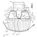
- FIG. 1is a perspective view of a bumper system, according to the present invention, illustrated in operational relationship with a motor vehicle.
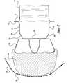
- FIG. 2is an exploded perspective view of the bumper system of FIG. 1 .
- FIG. 3is a sectional view taken along line 3 — 3 of FIG. 1 .
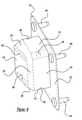
- FIG. 4is an exploded elevational view of a bumper beam and reinforcement of the bumper system of FIG. 1 .
- FIG. 5is an elevational view of a bumper beam and reinforcement of the bumper system of FIG. 1 .
- FIG. 6is a view similar to FIG. 5 illustrating a deformed stage.
- FIG. 7is a fragmentary elevational view of another embodiment, according to the present invention, of the bumper system of FIG. 1 .
- FIG. 8is a perspective view of a device of the bumper system of FIG. 7 .
- FIG. 9is a side elevational view of the device of the bumper system of FIG. 7 .
- FIG. 10is a plan view of the device of the bumper system of FIG. 7 .
- FIG. 11is a fragmentary plan view of the bumper system of FIG. 7 illustrating a first stage of a high-speed impact.
- FIG. 12is a view similar to FIG. 11 illustrating a second stage of a high-speed impact.
- FIG. 13is a view similar to FIG. 11 illustrating a third stage of a high-speed impact.
- FIG. 14is a view similar to FIG. 11 illustrating a fourth stage of a high-speed impact.
- a bumper system 10is illustrated in operational relationship with a motor vehicle, generally indicated at 12 .
- the bumper system 10is disposed at a front or forward end of the motor vehicle 12 . It should be appreciated that the bumper system 10 may be disposed at a rear or rearward end of the motor vehicle 12 . It should also be appreciated that, except for the bumper system 10 , the motor vehicle 12 is conventional and known in the art.
- the bumper system 10includes a bumper beam, generally indicated at 16 .
- the bumper beam 16extends laterally and is secured to a forward end 17 of a pair of front rails 18 by suitable means such as welding or mechanical fastening.
- the bumper beam 16is a hollow member having a general “B” cross-sectional shape.
- the bumper beam 16has a front or impact wall 20 extending generally vertically and laterally.
- the bumper beam 16also has an upper or top wall 22 and a lower or bottom wall 24 inclined longitudinally from the impact wall 20 and extending laterally.
- the bumper beam 16has a curved or arcuate forward corner wall 26 interconnecting the impact wall 20 and the upper and lower walls 22 and 24 .
- the bumper beam 16also has a rear or supporting wall 28 extending generally vertically and laterally from the upper and lower walls 22 and 24 .
- the bumper beam 16has a curved or arcuate rear corner wall 30 interconnecting the supporting wall 28 and the upper and lower walls 22 and 24 . It should be appreciated that the impact wall 20 has a height greater than the supporting wall 28 .
- the bumper beam 16also has a plurality of, preferably two generally horizontal interior walls 32 extending laterally and longitudinally forward toward the impact wall 20 .
- the bumper beam 16has a curved or arcuate inner corner wall 34 interconnecting the interior walls 32 and supporting wall 28 .
- the bumper beam 16has an inclined transition wall 36 extending laterally and longitudinally forward from the interior walls 32 and toward a center of the impact wall 20 and a curved or arcuate projection wall 38 interconnecting the ends of the transition walls 36 .
- the impact wall 20is formed as two portions with each portion extending from the front corner walls 26 and spaced vertically from each other to form a gap 40 therebetween.
- the projection wall 38is secured to the upper and lower portions of the impact wall 20 by suitable means such as welding or mechanical fastening to increase a stability of the bumper beam 16 against a “match boxing” behavior.
- the upper and lower portions of the impact wall 20have a plurality of apertures 42 extending therethrough and spaced laterally for a function to be described.
- a top wall of the rail 18is located vertically between the upper wall 22 and the top interior wall 32 of the bumper beam 16 and a lower wall of the rail 18 is located vertically between the lower wall 24 and the lower interior wall 32 of the bumper beam 16 in a symmetrical manner.
- the stiffness of the rail 18causes the two interior walls 32 to collapse prior to the upper and lower walls 22 and 24 collapse. It should be appreciated that this overlapping collapse assures a uniform energy absorption characteristic in high-speed impacts.
- the walls 22 , 24 , and 32may have a plurality of apertures (not shown) extending therethrough to achieve a desired crush stiffness of the bumper beam 16 .
- the bumper beam 16is made of a relatively rigid material such as metal.
- the bumper beam 16is integral, unitary, and formed as one-piece by manufacturing processes such as roll forming which a conventional process known in the art. It should also be appreciated that other manufacturing processes such as extruding and stamping may be used to form the bumper beam 16 . It should also be appreciated that the bumper beam 16 may be attached to a rearward end (not shown) of a pair of rear rails (not shown) of the motor vehicle 12 by suitable means such as welding.
- the bumper system 10includes an energy absorber 44 .
- the energy absorber 44extends laterally and is secured to the bumper beam 16 .
- the energy absorber 44has a plurality of projections 46 extending rearward therefrom and through the apertures 42 in the impact wall 20 .
- the energy absorber 44is a solid member having a generally trapezoidal shape with rear upper and lower lips 48 and SO extending rearward.
- the upper and lower lips 48 and 50have a generally arcuate or curved shape to extend over the front corner walls 26 of the bumper beam 16 .
- the energy absorber 44is made of a relatively deformable material such as foam.
- the bumper beam 16may have a horizontal sweep to reduce the depth of the deformable material of the energy absorber 44 . It should be appreciated that the apertures 42 in the impact wall 20 allow the energy absorber 44 to have local penetration in order to avoid excess compacting of the deformable material during a high-speed impact with an object (not shown).
- the bumper system 10further includes a fascia 50 extending laterally and vertically to cover the energy absorber 44 .
- the fascia 50is secured to vehicle structure (not shown) by suitable means such as fasteners (not shown).
- the fascia 50is made of a relatively rigid material such as plastic. It should be appreciated that the fascia 50 is conventional and known in the art.
- the bumper system 10also includes a reinforcement 52 disposed between the rails 18 and the bumper beam 16 to resist excessive centerline bending deformation and improve global stiffness of the bumper beam 16 .
- the reinforcement 52has a rear or base wall 54 extending generally vertically and laterally.
- the reinforcement 52also has a plurality of, preferably two generally horizontal side walls 56 extending laterally and longitudinally forward from the base wall 54 .
- the reinforcement 52has a curved or arcuate corner wall 58 interconnecting the side walls 56 and the base wall 54 .
- the reinforcement 52has an inclined transition wall 60 extending laterally and longitudinally forward from the side walls 56 and a curved or arcuate projection wall 62 interconnecting the ends of the transition walls 60 .
- the reinforcement 52is made of a metal material such as steel and is formed as a one-piece stamping by a stamping process, which is conventional and known in the art
- the reinforcement 52has the base wall 54 secured to the upper and lower portions of the rails 18 by suitable mean such as welding.
- the reinforcement 52also has the projection wall 62 disposed adjacent the projection wall 38 , the transition walls 60 disposed adjacent the transition walls 36 , the side walls 56 disposed adjacent the interior walls 32 , and the base wall 54 adjacent the supporting wall 28 and secured thereto by suitable means such as welding.
- the reinforcement 52is a monolithic structure being integral, unitary, and one-piece.
- the bumper system 10has a first stage or mode.
- the first modeat low speeds (i.e., less than or equal to approximately ten miles per hour), the bumper system 10 impacts an object such as a wall.
- the energy absorber 44is deformed and absorbs the energy of the impact without deforming the bumper beam 16 .
- the energy absorber 44is compressed longitudinally and expands vertically to absorb the impact energy and the slower impact speed will not have a tendency to deform or collapse the bumper beam 16 .
- the reinforcement 52allows the bumper beam 16 to elastically twist or bend without a permanent dent in the bumper beam 16 , thereby preventing replacement of the bumper beam 16 .
- the bumper system 10has a second stage or mode. In the second mode at high speeds (i.e., greater than approximately ten miles per hour), the bumper system 10 impacts an object such as the wall and the reinforcement 52 allows the bumper beam 16 to crush at centerline and limit intrusion into an occupant compartment of the vehicle 12 .
- the two interior walls 32initiate first stage plastic hinge points around the corner walls 34 to deform the walls 32 partially due to its geometry and partially due to the partial supporting of the vehicle structure such as the rail 18 .
- the deformable material of the energy absorber 44will be locally extruded into the hollow interior of the bumper beam 16 through the apertures 42 in the impact wall 20 .
- the upper and lower walls 22 and 24initiate second stage plastic hinge points around the corner walls 26 to deform the upper and lower walls 22 and 24 of the bumper beam 16 .
- the bumper beam 16will finally go into its compact stage by total deformation of all generally horizontal walls 22 , 24 , and 32 .
- the reinforcement 52allows the bumper system 10 to absorb more energy than traditional designs that hold their shape and transfer energy to other structure of the vehicle 12 .
- the reinforcement 52has less of a plan view arch shape or sweep than the bumper beam 16 itself, thereby allowing the reinforcement 52 to be made of less formable yet higher strength lower thickness steel which saves vehicle weight.
- the reinforcement 52reduces the moment or non-axial forces on the bumper beam 16 foundation points and acts as a “tie bar” or two-force member sharing the forces of the impact rather than allowing concentration of stresses at the bumper beam mounting points.
- FIGS. 7 through 10another embodiment 110 , according to the present invention, of the bumper system 10 is shown. Like parts of the bumper system 10 have like reference numerals increased by one hundred (100).
- the bumper system 110eliminates the reinforcement 52 described above and incorporates an energy absorbing member or device 170 .
- the energy absorbing device 170efficiently absorbs energy after the bumper beam 116 has collapsed, in turn, protecting the frame and structure of the vehicle 12 , which is expensive to repair.
- the energy absorbing device 170has a supporting wall 172 and side walls 174 extending from the supporting wall 172 to form a box-like cross-section.
- the energy absorbing device 170also has inclined transition walls 176 extending from the side walls 174 to an end wall 178 to form a closed section.
- the end wall 178is inclined relative to a plane parallel to the supporting wall 172 .
- the energy absorbing device 170may include first apertures 180 extending through the side walls 174 and/or second apertures 182 through the end wall 178 .
- the energy absorbing device 170is made of a metal material such as steel and is integral, unitary, and formed as a one-piece stamping by a stamping process, which is conventional and known in the art.
- the energy absorbing device 170is secured to an end of the rails 18 by suitable means such as fasteners 184 extending through the supporting wall 172 and a wall of the forward end 17 of the rails 18 .
- suitable meanssuch as fasteners 184 extending through the supporting wall 172 and a wall of the forward end 17 of the rails 18 .
- the operation of the bumper beam 116is similar to the bumper beam 16 .
- the bumper system 10has a first stage or mode as illustrated in FIGS. 11 and 12.
- the bumper system 110impacts an object such as a wall 186 .
- the energy absorber 144is deformed and absorbs the energy of the impact without deforming the bumper beam 116 .
- the energy absorber 144is compressed longitudinally and expands vertically to absorb the impact energy and the slower impact speed will not have a tendency to deform or collapse the bumper beam 116 .
- the bumper system 110has a second stage or mode as illustrated.
- the bumper system 110impacts an object such as the wall 186 .
- the energy absorbing device 170undergoes deformation.
- the two side walls 174initiate first stage plastic hinge points around the corner walls 175 to deform the side walls 174 partially due to its geometry and partially due to the partial supporting of the vehicle structure such as the rail 18 .
- the transition walls 176initiate second stage plastic hinge points around the corners thereof to deform the transition walls 176 of the energy absorbing device 170 as illustrated in FIG. 13 .
- the energy absorbing device 170finally goes into its compact stage by total deformation of all the walls 172 , 174 , 176 , and 178 as illustrated in FIG. 14 .
Landscapes
- Engineering & Computer Science (AREA)
- Mechanical Engineering (AREA)
- Vibration Dampers (AREA)
- Body Structure For Vehicles (AREA)
Abstract
Description
The present application claims priority from provisional application Serial No. 60/170,935, filed Dec. 15, 1999.
1. Field of the Invention
The present invention relates generally to bumpers for motor vehicles and, more specifically, to a bumper system for a motor vehicle.
2. Description of the Related Art
It is known to provide a bumper system for a front end or rear end of a motor vehicle. For a front end of the motor vehicle, the bumper system typically includes a bumper beam extending transversely and secured to a forward end of a pair of front rails, which extend longitudinally and are spaced transversely. The bumper system also includes an energy absorber extending transversely and secured to the bumper beam. The bumper system may include a fascia disposed over and covering the energy absorber.
It is also known that the bumper system protects a body of the motor vehicle from low speed impact with an object through elastic or semi-plastic deformation of the energy absorber. It is further known that the bumper system is an absorber for high-speed impact with an object through major plastic deformation of the bumper beam. It is yet further known that bumper beams of bumper systems tend to buckle at a centerline in an uncontrolled fashion during low and highspeed impacts.
Although the above bumper system has worked, it suffers from the disadvantage that the bumper beam has a constant cross-section which is either too weak to resist low speed impact at a center thereof or makes it too strong to absorb impact energy before the supporting vehicle rails collapse under the motor vehicle. As a result, it is desirable to provide a bumper system having a bumper beam which will better balance both low speed impact protection and high speed energy absorption for a bumper system of a motor vehicle. It is also desirable to provide a reinforcement for a bumper beam that reduces damage to the bumper beam at low speed impacts but allows the bumper beam to crush at high-speed impacts. It is further desirable to provide a metal device positioned behind or inside a bumper beam that when impacted crushes with an efficient and effective energy curve. Therefore, there is a need in the art to provide a bumper system that meets these desires.
Accordingly, the present invention is a bumper system for a motor vehicle. The bumper system includes an energy absorber and a bumper beam connected to the energy absorber and for connection to vehicle structure and having a general B shape. The bumper system also includes a member disposed between the bumper beam and a rail of the motor vehicle to absorb energy during an impact with an object by the bumper system.
One advantage of the present invention is that a new bumper system is provided for a motor vehicle. Another advantage of the present invention is that the bumper system includes a bumper beam made from a manufacturing process such as a roll formed process or an extrusion process with a generally “B” shaped cross-section which balances both low-speed impact and high-speed impact of the motor vehicle. Yet another advantage of the present invention is that the bumper system has a reinforcement attached to a “B” shaped bumper beam that reduces damage to the bumper beam at a low speed impact but allows the bumper beam to crush at a high-speed impact. Still another advantage of the present invention is that the bumper system includes a centerline bumper reinforcement of unique cross-sectional geometry, allowing the bumper beam to crush at high speed yet resist low speed damage. A further advantage of the present invention is that the bumper beam reinforcement resists excessive centerline bending deformation. Yet a further advantage of the present invention is that the bumper system includes a metal device is positioned behind or inside a vehicle bumper beam that when impacted crushes with an efficient and effective energy curve. Still a further advantage of the present invention is that the metal device is relatively low cost to manufacture compared to more expensive hydraulic strut assemblies. Another advantage of the present invention is that the metal device has a unique geometry and simplicity and crushes in a very efficient manner. Yet another advantage of the present invention is that the metal device reduces cost during repair of a vehicle after an incidental collision. Still another advantage of the present invention is that the metal device is low cost to manufacture, lighter than traditional strut designs, low cost to assembly and service in the field, very efficient crush characteristics (square load-deflection curve), ease of design flexibility for different vehicles, ease of design to commonize part between vehicles, greatly reduces the cost to repair, and offers a controlled joint to bumper beam which allows for improved high speed energy management with lower intrusion into an occupant compartment of the vehicle.
Other features and advantages of the present invention will be readily appreciated, as the same becomes better understood, after reading the subsequent description when considered in connection with the accompanying drawings.
FIG. 1 is a perspective view of a bumper system, according to the present invention, illustrated in operational relationship with a motor vehicle.
FIG. 2 is an exploded perspective view of the bumper system of FIG.1.
FIG. 3 is a sectional view taken alongline 3—3 of FIG.1.
FIG. 4 is an exploded elevational view of a bumper beam and reinforcement of the bumper system of FIG.1.
FIG. 5 is an elevational view of a bumper beam and reinforcement of the bumper system of FIG.1.
FIG. 6 is a view similar to FIG. 5 illustrating a deformed stage.
FIG. 7 is a fragmentary elevational view of another embodiment, according to the present invention, of the bumper system of FIG.1.
FIG. 8 is a perspective view of a device of the bumper system of FIG.7.
FIG. 9 is a side elevational view of the device of the bumper system of FIG.7.
FIG. 10 is a plan view of the device of the bumper system of FIG.7.
FIG. 11 is a fragmentary plan view of the bumper system of FIG. 7 illustrating a first stage of a high-speed impact.
FIG. 12 is a view similar to FIG. 11 illustrating a second stage of a high-speed impact.
FIG. 13 is a view similar to FIG. 11 illustrating a third stage of a high-speed impact.
FIG. 14 is a view similar to FIG. 11 illustrating a fourth stage of a high-speed impact.
Referring to the drawings and in particular FIG. 1, one embodiment of abumper system 10, according to the present invention, is illustrated in operational relationship with a motor vehicle, generally indicated at12. Thebumper system 10 is disposed at a front or forward end of themotor vehicle 12. It should be appreciated that thebumper system 10 may be disposed at a rear or rearward end of themotor vehicle 12. It should also be appreciated that, except for thebumper system 10, themotor vehicle 12 is conventional and known in the art.
As illustrated in FIGS. 2 through 6, thebumper system 10 includes a bumper beam, generally indicated at16. Thebumper beam 16 extends laterally and is secured to aforward end 17 of a pair offront rails 18 by suitable means such as welding or mechanical fastening. Thebumper beam 16 is a hollow member having a general “B” cross-sectional shape. Thebumper beam 16 has a front orimpact wall 20 extending generally vertically and laterally. Thebumper beam 16 also has an upper ortop wall 22 and a lower orbottom wall 24 inclined longitudinally from theimpact wall 20 and extending laterally. Thebumper beam 16 has a curved or arcuateforward corner wall 26 interconnecting theimpact wall 20 and the upper andlower walls bumper beam 16 also has a rear or supportingwall 28 extending generally vertically and laterally from the upper andlower walls bumper beam 16 has a curved or arcuaterear corner wall 30 interconnecting the supportingwall 28 and the upper andlower walls impact wall 20 has a height greater than the supportingwall 28.
Thebumper beam 16 also has a plurality of, preferably two generally horizontalinterior walls 32 extending laterally and longitudinally forward toward theimpact wall 20. Thebumper beam 16 has a curved or arcuateinner corner wall 34 interconnecting theinterior walls 32 and supportingwall 28. Thebumper beam 16 has aninclined transition wall 36 extending laterally and longitudinally forward from theinterior walls 32 and toward a center of theimpact wall 20 and a curved orarcuate projection wall 38 interconnecting the ends of thetransition walls 36. Theimpact wall 20 is formed as two portions with each portion extending from thefront corner walls 26 and spaced vertically from each other to form agap 40 therebetween. Theprojection wall 38 is secured to the upper and lower portions of theimpact wall 20 by suitable means such as welding or mechanical fastening to increase a stability of thebumper beam 16 against a “match boxing” behavior. The upper and lower portions of theimpact wall 20 have a plurality ofapertures 42 extending therethrough and spaced laterally for a function to be described.
As illustrated in FIG. 3, a top wall of therail 18 is located vertically between theupper wall 22 and the topinterior wall 32 of thebumper beam 16 and a lower wall of therail 18 is located vertically between thelower wall 24 and the lowerinterior wall 32 of thebumper beam 16 in a symmetrical manner. As a result, the stiffness of therail 18 causes the twointerior walls 32 to collapse prior to the upper andlower walls walls bumper beam 16.
Thebumper beam 16 is made of a relatively rigid material such as metal. Thebumper beam 16 is integral, unitary, and formed as one-piece by manufacturing processes such as roll forming which a conventional process known in the art. It should also be appreciated that other manufacturing processes such as extruding and stamping may be used to form thebumper beam 16. It should also be appreciated that thebumper beam 16 may be attached to a rearward end (not shown) of a pair of rear rails (not shown) of themotor vehicle 12 by suitable means such as welding.
Thebumper system 10 includes anenergy absorber 44. Theenergy absorber 44 extends laterally and is secured to thebumper beam 16. Theenergy absorber 44 has a plurality ofprojections 46 extending rearward therefrom and through theapertures 42 in theimpact wall 20. Theenergy absorber 44 is a solid member having a generally trapezoidal shape with rear upper and lower lips48 and SO extending rearward. The upper andlower lips 48 and50 have a generally arcuate or curved shape to extend over thefront corner walls 26 of thebumper beam 16. Theenergy absorber 44 is made of a relatively deformable material such as foam. Thebumper beam 16 may have a horizontal sweep to reduce the depth of the deformable material of theenergy absorber 44. It should be appreciated that theapertures 42 in theimpact wall 20 allow theenergy absorber 44 to have local penetration in order to avoid excess compacting of the deformable material during a high-speed impact with an object (not shown).
Thebumper system 10 further includes afascia 50 extending laterally and vertically to cover theenergy absorber 44. Thefascia 50 is secured to vehicle structure (not shown) by suitable means such as fasteners (not shown). Thefascia 50 is made of a relatively rigid material such as plastic. It should be appreciated that thefascia 50 is conventional and known in the art.
Thebumper system 10 also includes areinforcement 52 disposed between therails 18 and thebumper beam 16 to resist excessive centerline bending deformation and improve global stiffness of thebumper beam 16. Thereinforcement 52 has a rear orbase wall 54 extending generally vertically and laterally. Thereinforcement 52 also has a plurality of, preferably two generallyhorizontal side walls 56 extending laterally and longitudinally forward from thebase wall 54. Thereinforcement 52 has a curved orarcuate corner wall 58 interconnecting theside walls 56 and thebase wall 54. Thereinforcement 52 has aninclined transition wall 60 extending laterally and longitudinally forward from theside walls 56 and a curved orarcuate projection wall 62 interconnecting the ends of thetransition walls 60. Thereinforcement 52 is made of a metal material such as steel and is formed as a one-piece stamping by a stamping process, which is conventional and known in the art Thereinforcement 52 has thebase wall 54 secured to the upper and lower portions of therails 18 by suitable mean such as welding. Thereinforcement 52 also has theprojection wall 62 disposed adjacent theprojection wall 38, thetransition walls 60 disposed adjacent thetransition walls 36, theside walls 56 disposed adjacent theinterior walls 32, and thebase wall 54 adjacent the supportingwall 28 and secured thereto by suitable means such as welding. Thereinforcement 52 is a monolithic structure being integral, unitary, and one-piece.
In operation, thebumper system 10 has a first stage or mode. In the first mode at low speeds (i.e., less than or equal to approximately ten miles per hour), thebumper system 10 impacts an object such as a wall. Theenergy absorber 44 is deformed and absorbs the energy of the impact without deforming thebumper beam 16. In this case, theenergy absorber 44 is compressed longitudinally and expands vertically to absorb the impact energy and the slower impact speed will not have a tendency to deform or collapse thebumper beam 16. As illustrated in FIG. 6, thereinforcement 52 allows thebumper beam 16 to elastically twist or bend without a permanent dent in thebumper beam 16, thereby preventing replacement of thebumper beam 16.
Thebumper system 10 has a second stage or mode. In the second mode at high speeds (i.e., greater than approximately ten miles per hour), thebumper system 10 impacts an object such as the wall and thereinforcement 52 allows thebumper beam 16 to crush at centerline and limit intrusion into an occupant compartment of thevehicle 12. The twointerior walls 32 initiate first stage plastic hinge points around thecorner walls 34 to deform thewalls 32 partially due to its geometry and partially due to the partial supporting of the vehicle structure such as therail 18. The deformable material of theenergy absorber 44 will be locally extruded into the hollow interior of thebumper beam 16 through theapertures 42 in theimpact wall 20. The upper andlower walls corner walls 26 to deform the upper andlower walls bumper beam 16. Thebumper beam 16 will finally go into its compact stage by total deformation of all generallyhorizontal walls reinforcement 52 allows thebumper system 10 to absorb more energy than traditional designs that hold their shape and transfer energy to other structure of thevehicle 12. It should also be appreciated that thereinforcement 52 has less of a plan view arch shape or sweep than thebumper beam 16 itself, thereby allowing thereinforcement 52 to be made of less formable yet higher strength lower thickness steel which saves vehicle weight. It should further be appreciated that thereinforcement 52 reduces the moment or non-axial forces on thebumper beam 16 foundation points and acts as a “tie bar” or two-force member sharing the forces of the impact rather than allowing concentration of stresses at the bumper beam mounting points.
Referring to FIGS. 7 through 10, anotherembodiment 110, according to the present invention, of thebumper system 10 is shown. Like parts of thebumper system 10 have like reference numerals increased by one hundred (100). In this embodiment illustrated in FIG. 7, thebumper system 110 eliminates thereinforcement 52 described above and incorporates an energy absorbing member ordevice 170. Theenergy absorbing device 170 efficiently absorbs energy after thebumper beam 116 has collapsed, in turn, protecting the frame and structure of thevehicle 12, which is expensive to repair. Theenergy absorbing device 170 has a supportingwall 172 andside walls 174 extending from the supportingwall 172 to form a box-like cross-section. Theenergy absorbing device 170 also has inclinedtransition walls 176 extending from theside walls 174 to anend wall 178 to form a closed section. Theend wall 178 is inclined relative to a plane parallel to the supportingwall 172. Theenergy absorbing device 170 may includefirst apertures 180 extending through theside walls 174 and/orsecond apertures 182 through theend wall 178. Theenergy absorbing device 170 is made of a metal material such as steel and is integral, unitary, and formed as a one-piece stamping by a stamping process, which is conventional and known in the art. Theenergy absorbing device 170 is secured to an end of therails 18 by suitable means such asfasteners 184 extending through the supportingwall 172 and a wall of theforward end 17 of therails 18. The operation of thebumper beam 116 is similar to thebumper beam 16.
In operation, thebumper system 10 has a first stage or mode as illustrated in FIGS. 11 and 12. In the first mode at low speeds (i.e., less than or equal to approximately ten miles per hour), thebumper system 110 impacts an object such as awall 186. Theenergy absorber 144 is deformed and absorbs the energy of the impact without deforming thebumper beam 116. In this case, theenergy absorber 144 is compressed longitudinally and expands vertically to absorb the impact energy and the slower impact speed will not have a tendency to deform or collapse thebumper beam 116.
Referring to FIGS. 12 and 14, thebumper system 110 has a second stage or mode as illustrated. In the second mode at high speeds (i.e., greater than approximately ten miles per hour), thebumper system 110 impacts an object such as thewall 186. After thebumper beam 116 finally go into its compact stage by total deformation, theenergy absorbing device 170 undergoes deformation. The twoside walls 174 initiate first stage plastic hinge points around thecorner walls 175 to deform theside walls 174 partially due to its geometry and partially due to the partial supporting of the vehicle structure such as therail 18. Thetransition walls 176 initiate second stage plastic hinge points around the corners thereof to deform thetransition walls 176 of theenergy absorbing device 170 as illustrated in FIG.13. Theenergy absorbing device 170 finally goes into its compact stage by total deformation of all thewalls
The present invention has been described in an illustrative manner. It is to be understood that the terminology, which has been used, is intended to be in the nature of words of description rather than of limitation.
Many modifications and variations of the present invention are possible in light of the above teachings. Therefore, within the scope of the appended claims, the present invention may be practiced other than as specifically described.
Claims (12)
1. A bumper system for a motor vehicle comprising:
an energy absorber; and
a bumper beam connected to said energy absorber and adapted for connection to vehicle structure and having a general B shape, said bumper beam having a front wall connected to said energy absorber and a rear wall adapted for connection to the vehicle structure and a projection extending from said rear wall toward said front wall to form a channel therein; and
a member comprising a reinforcement having a portion extending longitudinally and being at least partially disposed within said channel of said bumper beam, said reinforcement being located between said bumper beam and a rail of the motor vehicle to absorb energy during an impact with an object by said bumper system.
2. A bumper system as set forth inclaim 1 wherein said reinforcement has a base wall extending vertically and laterally.
3. A bumper system as set forth inclaim 2 wherein said reinforcement has a plurality of side walls extending generally perpendicularly from said base wall and spaced from each other.
4. A bumper system as set forth inclaim 3 wherein said reinforcement has a transition wall extending from said side walls toward each other.
5. A bumper system as set forth inclaim 4 wherein said reinforcement has a projection wall being arcuate in shape and interconnecting said transition walls.
6. A bumper system as set forth inclaim 1 wherein said reinforcement is made of a metal material.
7. A bumper system as set forth inclaim 1 wherein said reinforcement is secured to said bumper beam and adapted to be secured to the rail by either one of welds or mechanical fasteners.
8. A bumper system as set forth inclaim 1 wherein said bumper beam is integral, unitary, and formed as one-piece.
9. A bumper system for a motor vehicle comprising:
an energy absorber;
a bumper beam interconnecting said energy absorber and vehicle structure and having a general B shape, said bumper beam having a front wall connected to said energy absorber and a rear wall adapted for connection to the vehicle structure and a projection extending from said rear wall toward said front wall to form a channel therein; and
a reinforcement having a portion disposed in said channel of said bumper beam, said reinforcement being located between said bumper beam and a rail of the motor vehicle to absorb energy during an impact with an object by said bumper system.
10. A bumper system as set forth inclaim 9 wherein said reinforcement has a base wall extending vertically and laterally.
11. A bumper system as set forth inclaim 10 wherein said reinforcement has a plurality of side walls extending generally perpendicularly from said base wall and spaced from each other.
12. A bumper system as set forth inclaim 11 wherein said reinforcement has a transition wall extending from said side walls inwardly toward each other and a projection wall being arcuate in shape and interconnecting said transition walls.
Priority Applications (1)
| Application Number | Priority Date | Filing Date | Title |
|---|---|---|---|
| US09/707,110US6485072B1 (en) | 1999-12-15 | 2000-11-06 | Bumper system for motor vehicles |
Applications Claiming Priority (2)
| Application Number | Priority Date | Filing Date | Title |
|---|---|---|---|
| US17093599P | 1999-12-15 | 1999-12-15 | |
| US09/707,110US6485072B1 (en) | 1999-12-15 | 2000-11-06 | Bumper system for motor vehicles |
Publications (1)
| Publication Number | Publication Date |
|---|---|
| US6485072B1true US6485072B1 (en) | 2002-11-26 |
Family
ID=22621874
Family Applications (3)
| Application Number | Title | Priority Date | Filing Date |
|---|---|---|---|
| US09/707,110Expired - Fee RelatedUS6485072B1 (en) | 1999-12-15 | 2000-11-06 | Bumper system for motor vehicles |
| US09/732,281Expired - LifetimeUS6460909B2 (en) | 1999-12-15 | 2000-12-07 | Bumper system for motor vehicles |
| US10/206,494Expired - LifetimeUS6663151B2 (en) | 1999-12-15 | 2002-07-26 | Bumper system for motor vehicles |
Family Applications After (2)
| Application Number | Title | Priority Date | Filing Date |
|---|---|---|---|
| US09/732,281Expired - LifetimeUS6460909B2 (en) | 1999-12-15 | 2000-12-07 | Bumper system for motor vehicles |
| US10/206,494Expired - LifetimeUS6663151B2 (en) | 1999-12-15 | 2002-07-26 | Bumper system for motor vehicles |
Country Status (3)
| Country | Link |
|---|---|
| US (3) | US6485072B1 (en) |
| EP (1) | EP1108622B1 (en) |
| DE (1) | DE60017697T2 (en) |
Cited By (58)
| Publication number | Priority date | Publication date | Assignee | Title |
|---|---|---|---|---|
| US20030075953A1 (en)* | 2001-09-26 | 2003-04-24 | Sumitomo Chemical Company, Limited | Impact energy absorbing component |
| US20030178861A1 (en)* | 2000-09-20 | 2003-09-25 | Lars Wikstrom | Bumper beam arrangement |
| US20030189344A1 (en)* | 2001-04-16 | 2003-10-09 | Darin Evans | Bumper system with face-mounted energy absorber |
| US6663150B1 (en)* | 2002-06-06 | 2003-12-16 | Netshape Corporation | Bumper with integrated energy absorber and beam |
| US6684505B2 (en)* | 1999-12-14 | 2004-02-03 | Accra Teknik Ab | Method for manufacturing a bumper bar |
| US6695366B2 (en)* | 2001-07-27 | 2004-02-24 | Talfourd-Jones Inc. | Energy absorbing bumper |
| US6698820B2 (en)* | 2001-09-18 | 2004-03-02 | Toyota Jidosha Kabushiki Kaisha | Fender structure of vehicle |
| US6712411B2 (en)* | 2001-07-30 | 2004-03-30 | Aisin Seiki Kabushiki Kaisha | Bumper device for vehicles and bumper stay |
| US20040135382A1 (en)* | 2002-10-29 | 2004-07-15 | Aisin Seiki Kabushiki Kaisha | Bumper apparatus for vehicle |
| US20040154158A1 (en)* | 2001-06-21 | 2004-08-12 | Anders Sundgren | Apparatus and method for manufacturing an automotive beam |
| US6817638B1 (en)* | 2003-06-27 | 2004-11-16 | Hanwha L&C Corporation | Bumper system |
| US20040256867A1 (en)* | 2003-06-18 | 2004-12-23 | Darin Evans | Bumper system with "W" beam and energy absorber |
| US6890011B2 (en)* | 2001-10-05 | 2005-05-10 | Daimlerchrysler Ag | Energy-absorbing bumper |
| US20050099027A1 (en)* | 2003-11-12 | 2005-05-12 | Seksaria Dinesh C. | Bumper system for a motor vehicle |
| US20050162631A1 (en)* | 2004-01-26 | 2005-07-28 | Graber Donald G. | Cross member for vehicle bumper bar and method for making same |
| US6971691B1 (en) | 2004-06-25 | 2005-12-06 | Shape Corporation | Vehicle bumper beam |
| US20050285416A1 (en)* | 2004-06-25 | 2005-12-29 | Heatherington David W | Vehicle bumper beam |
| US20060028037A1 (en)* | 2004-08-05 | 2006-02-09 | Honda Motor Co., Ltd. | Vehicle bumper |
| US20060028032A1 (en)* | 2004-08-06 | 2006-02-09 | Karl Henseleit | Vehicle bumper and method of making same |
| US20060066088A1 (en)* | 2004-09-30 | 2006-03-30 | Hier Michael J | Inflatable airbag cushion formed with a blown elastomer core and methods of using and manufacturing same |
| US20060082179A1 (en)* | 2004-10-19 | 2006-04-20 | Depue Todd L | Automotive trim assembly having impact countermeasures and method of making the same |
| US20060082190A1 (en)* | 2004-10-19 | 2006-04-20 | Cowelchuk Glenn A | Automotive armrest with soft feel and method of making the same |
| US20060082106A1 (en)* | 2004-10-20 | 2006-04-20 | Hier Michael J | Automotive trim assembly having an integrated airbag door |
| US20060082109A1 (en)* | 2004-10-20 | 2006-04-20 | Hier Michael J | Method of making an automotive trim assembly having an integrated airbag door |
| US20060082173A1 (en)* | 2004-10-19 | 2006-04-20 | Cowelchuk Glenn A | Automotive trim part with applique and method of making same |
| US20060097544A1 (en)* | 2004-11-09 | 2006-05-11 | Cowelchuk Glenn A | Automotive interior trim assembly and method |
| US20060097536A1 (en)* | 2004-11-10 | 2006-05-11 | Depue Todd L | Automotive compartment having an integrated spring mechanism and method of making the same |
| US20060097545A1 (en)* | 2004-11-09 | 2006-05-11 | Cowelchuk Glenn A | Vehicle door trim bolster with multi-feel cover and method of making the same |
| US7066508B1 (en)* | 2005-03-31 | 2006-06-27 | Ford Global Technologies, Llc | Bumper cross-section with hinges |
| US7197824B1 (en) | 2004-07-20 | 2007-04-03 | Trim Trends, Co., Llc | Cross member for vehicle bumper bar and method for making same |
| US20070176440A1 (en)* | 2006-02-02 | 2007-08-02 | Joseph G. Burgess | Vehicle bumper and method of making same |
| EP1842731A1 (en)* | 2006-04-05 | 2007-10-10 | Ford Global Technologies, LLC. | Bumper system |
| US20070246956A1 (en)* | 2006-04-24 | 2007-10-25 | Honda Motor Co., Ltd. | Vehicle bumper structure |
| US20080054655A1 (en)* | 2006-08-31 | 2008-03-06 | Mazda Motor Corporation | Vehicle bumper structure |
| US20080079273A1 (en)* | 2006-10-03 | 2008-04-03 | Ford Global Technologies, Llc | Underrun energy-absorbing structure for a vehicle |
| US20080284183A1 (en)* | 2007-05-15 | 2008-11-20 | Shape Corporation | Impact beam with double-wall face |
| US7478854B2 (en) | 2004-10-19 | 2009-01-20 | International Automotive Components Group North America, Inc. | Automotive handle with soft feel and method of making the same |
| US20090058112A1 (en)* | 2007-08-30 | 2009-03-05 | Gm Global Technology Operations, Inc. | Impact-limiting system of a motor vehicle |
| US20090102210A1 (en)* | 2006-05-19 | 2009-04-23 | Michael Tanskanen | Crash Box for a Vehicle |
| EP1880905A3 (en)* | 2006-07-19 | 2009-08-05 | Alcan Technology & Management AG | Bumper with supports |
| US20090236866A1 (en)* | 2006-07-27 | 2009-09-24 | Hwa Sun Lee | Bumper reinforcement for an automobile |
| US20090315346A1 (en)* | 2008-06-20 | 2009-12-24 | David William Schelberg | Bumper reinforcement extension |
| US20100109355A1 (en)* | 2007-04-06 | 2010-05-06 | Compagnie Plastic Omnium | Assembly of an impact beam and an absorber |
| US7866716B2 (en) | 2008-04-08 | 2011-01-11 | Flex-N-Gate Corporation | Energy absorber for vehicle |
| US20120032459A1 (en)* | 2006-10-12 | 2012-02-09 | Magna Automotive Services Gmbh | Energy Absorption Device, Especially For Non-Axial Loads |
| US8408613B1 (en)* | 2011-10-18 | 2013-04-02 | GM Global Technology Operations LLC | Energy absorber for automotive bumper |
| US20130257070A1 (en)* | 2012-03-29 | 2013-10-03 | Honda Motor Co., Ltd | Bumper structure |
| US20140138985A1 (en)* | 2012-11-20 | 2014-05-22 | Hyundai Motor Company | Bumper rail for vehicle |
| US9327662B1 (en) | 2014-11-24 | 2016-05-03 | Toyota Motor Engineering & Manufacturing North America, Inc. | Bumper assemblies including lower reinforcement members |
| US9327592B2 (en)* | 2014-03-20 | 2016-05-03 | GM Global Technology Operations LLC | Bumper with integrated auxilliary cooler |
| US9580030B2 (en) | 2015-04-08 | 2017-02-28 | Toyota Motor Engineering & Manufacturing North America, Inc. | Bumper assemblies including lower reinforcement members |
| US9975507B2 (en) | 2016-10-06 | 2018-05-22 | Ford Global Technologies, Llc | Reinforcement block |
| US10065587B2 (en) | 2015-11-23 | 2018-09-04 | Flex|N|Gate Corporation | Multi-layer energy absorber |
| US20190061658A1 (en)* | 2015-12-08 | 2019-02-28 | Gestamp Hardtech Ab | Bumper Beam |
| DE102007033764B4 (en) | 2006-07-19 | 2020-06-10 | Constellium Switzerland Ag | Bumper with brackets |
| CN112236333A (en)* | 2018-06-14 | 2021-01-15 | 日本制铁株式会社 | Closed-section structural member with high crash performance and vehicle body frame |
| US11155303B2 (en)* | 2019-12-18 | 2021-10-26 | GM Global Technology Operations LLC | Load deflection system for small overlap impact |
| US20220363216A1 (en)* | 2019-12-19 | 2022-11-17 | Bayerische Motoren Werke Aktiengesellschaft | Pedestrian Protection Device for a Motor Vehicle |
Families Citing this family (43)
| Publication number | Priority date | Publication date | Assignee | Title |
|---|---|---|---|---|
| DE19912272A1 (en)* | 1999-03-18 | 2000-09-28 | Benteler Werke Ag | Bumper assembly |
| US6874831B1 (en)* | 2000-07-06 | 2005-04-05 | Compagnie Plastic Omnium | Front structure for a motor vehicle |
| US6540276B2 (en)* | 2000-11-09 | 2003-04-01 | Aisin Seiki Kabushiki Kaisha | Bumper reinforcement structure |
| ITMI20011170A1 (en)* | 2001-06-01 | 2002-12-01 | Adlev Srl | PROTECTION STRUCTURE FOR VEHICLES, SUITABLE FOR USE, IN PARTICULAR, IN THE EVENT OF IMPACTS WITH PEDESTRIANS |
| DE10137911A1 (en)* | 2001-07-05 | 2003-01-16 | Dynamit Nobel Kunststoff Gmbh | Bumper support for improved pedestrian protection in motor vehicles |
| DE10154113A1 (en)* | 2001-11-03 | 2003-05-15 | Opel Adam Ag | Front structure of a motor vehicle |
| US6513843B1 (en)* | 2002-02-21 | 2003-02-04 | Ford Global Technologies, Inc. | Pedestrian protection leg spoiler |
| EP1386794A1 (en)* | 2002-07-24 | 2004-02-04 | Ford Global Technologies, Inc. | Impact energy transmitting arrangement |
| US6739634B1 (en)* | 2002-08-01 | 2004-05-25 | Celt-Taras Pagan | Gel-air impact bumper and retractable impact spoiler with attached impact hood shield |
| US6886872B2 (en)* | 2002-12-25 | 2005-05-03 | Mazda Motor Corporation | Automobile bumper structure |
| US6726260B1 (en)* | 2003-02-20 | 2004-04-27 | General Motors Corporation | Extending bumper with combined stiffener and method |
| US7055886B2 (en)* | 2003-03-28 | 2006-06-06 | Shape Corporation | Low-profile high-strength vehicle door beam |
| US6923482B2 (en) | 2003-06-27 | 2005-08-02 | Magna International Inc. | Multiple material bumper beam |
| FR2864811B1 (en)* | 2004-01-07 | 2008-08-22 | Renault Sas | IMPACT PROTECTION DEVICE FOR A MOTOR VEHICLE |
| EP1582413A1 (en)* | 2004-03-30 | 2005-10-05 | Ford Global Technologies, Inc. | A bumper device for a vehicle |
| US7571942B2 (en)* | 2005-01-03 | 2009-08-11 | Edward Shapiro | Universal floor and bucket protection devices, systems, and methods |
| US7198309B2 (en)* | 2005-03-23 | 2007-04-03 | Nissan Technical Center North America, Inc. | Vehicle bumper |
| US7726428B2 (en)* | 2005-10-12 | 2010-06-01 | Chrysler Group Llc | A/C condenser damage protection device |
| US7399027B2 (en)* | 2006-01-06 | 2008-07-15 | Ford Global Technologies, Llc | Automotive front end fascia with integrated structural member |
| US8141918B2 (en)* | 2006-02-24 | 2012-03-27 | Honda Motor Co., Ltd. | Pedestrian bumper system and method |
| FR2908717B1 (en)* | 2006-11-20 | 2010-03-12 | Renault Sas | AUTOMOTIVE VEHICLE ARRANGEMENT FOR THE PROTECTION OF PIETONS IN CASES OF FRONTAL SHOCK |
| FR2920725B1 (en)* | 2007-09-11 | 2010-05-14 | Peugeot Citroen Automobiles Sa | MOTOR VEHICLE |
| JP4728314B2 (en)* | 2007-11-26 | 2011-07-20 | 本田技研工業株式会社 | Bumper structure for vehicles |
| US7959197B2 (en)* | 2008-10-30 | 2011-06-14 | Shape Corp. | Bumper beam with multi-concavity-defining cross section |
| DE102010056390A1 (en)* | 2010-12-28 | 2012-06-28 | GM Global Technology Operations LLC | Front area of a vehicle and vehicle |
| EP2683592B1 (en)* | 2011-03-07 | 2015-05-20 | Faurecia Exteriors GmbH | Force-deflecting component for a motor vehicle for protecting against an impact of a curb edge against an underside of the motor vehicle |
| US8408636B1 (en) | 2011-11-15 | 2013-04-02 | Toyota Motor Corporation | Motor vehicles having bumper counter rotation brackets |
| DE102013002307A1 (en) | 2013-02-06 | 2014-08-07 | GM Global Technology Operations LLC (n. d. Ges. d. Staates Delaware) | Front end for a motor vehicle |
| US9409218B2 (en)* | 2013-05-01 | 2016-08-09 | Tesla Motors, Inc. | Extrusion piece with dissimilar ends |
| JP6098433B2 (en) | 2013-08-21 | 2017-03-22 | マツダ株式会社 | Vehicle front structure |
| JP6094426B2 (en) | 2013-08-21 | 2017-03-15 | マツダ株式会社 | Vehicle front structure |
| US8950800B1 (en) | 2013-11-11 | 2015-02-10 | Ford Global Technologies, Llc | Deployable lower leg stiffener for pedestrian protection |
| JP6131837B2 (en) | 2013-11-15 | 2017-05-24 | マツダ株式会社 | Vehicle front structure |
| US9150175B1 (en)* | 2014-09-18 | 2015-10-06 | Ford Global Technologies, Llc | Vehicle front end airbag assembly and system |
| US9216622B1 (en)* | 2014-10-13 | 2015-12-22 | Ford Global Technologies, Llc | Facing assembly for vehicle including towing cable guide |
| JP6584168B2 (en)* | 2015-06-30 | 2019-10-02 | ダイハツ工業株式会社 | Front bumper |
| GB2539975B (en)* | 2015-09-24 | 2017-05-17 | Ford Global Tech Llc | Deployable pedestrian safety device for vehicles |
| EP3393861A1 (en) | 2015-12-23 | 2018-10-31 | SABIC Global Technologies B.V. | Hybrid/composite energy-absorbing lower member for automobiles and process for making the same |
| US9821754B2 (en)* | 2016-02-26 | 2017-11-21 | Ford Global Technologies, Llc | Spring assist lock and release lower leg front-end stiffener |
| DE102016013877A1 (en)* | 2016-11-19 | 2017-10-12 | Daimler Ag | Support arrangement for a bumper of a motor vehicle |
| US10532718B2 (en) | 2017-05-18 | 2020-01-14 | Toyota Motor Engineering & Manufacturing North America, Inc. | Bumper assemblies including deformable upper energy absorbers |
| US10953844B2 (en)* | 2017-06-29 | 2021-03-23 | Ford Global Technologies, Llc | External airbag system for pedestrian protection |
| DE102021204383B4 (en) | 2021-04-30 | 2024-11-07 | Volkswagen Aktiengesellschaft | Assembly arranged in a front end of a motor vehicle with a carrier protection structure for a mounting carrier |
Citations (73)
| Publication number | Priority date | Publication date | Assignee | Title |
|---|---|---|---|---|
| US1581432A (en) | 1925-02-18 | 1926-04-20 | American Chain & Cable Co | Automobile end fender |
| US1935447A (en) | 1933-03-02 | 1933-11-14 | Hoffman Otto | Pneumatic bumper |
| US2604349A (en) | 1949-08-24 | 1952-07-22 | Charles F Martinetz | Noninterlocking automobile bumper |
| US2753193A (en) | 1955-07-11 | 1956-07-03 | Design Rite Company | Trailer hitch and mounting bracket means therefor |
| US2828144A (en) | 1954-01-28 | 1958-03-25 | Joseph W Taylor | Trailer hitch assembly |
| US3412628A (en) | 1966-07-14 | 1968-11-26 | Koppy Tool Corp | Shock absorbing structural member |
| US3495474A (en) | 1966-11-24 | 1970-02-17 | Nissan Motor | Impact absorbing means for vehicles |
| US3578358A (en) | 1969-08-19 | 1971-05-11 | Donald F Reynolds | Frame hitch and step bumper |
| DE2137517A1 (en) | 1971-07-27 | 1973-02-08 | Volkswagenwerk Ag | VEHICLE FRAME WITH ENERGY CONSUMPTION TRAINED END AREA |
| US3739882A (en) | 1970-04-09 | 1973-06-19 | Volkswagenwerk Ag | Shock absorbing device especially for vehicles |
| US3819224A (en) | 1973-05-10 | 1974-06-25 | Gen Motors Corp | Vehicle body construction |
| US3831997A (en) | 1973-03-22 | 1974-08-27 | Ford Motor Co | Controlled collapse vehicle front end structure |
| US3885817A (en) | 1974-02-06 | 1975-05-27 | Fredrick W Christian | Trailer hitch |
| US3888515A (en) | 1972-12-14 | 1975-06-10 | Charles M Winter | Trailer hitch mechanism |
| US3897095A (en)* | 1973-12-07 | 1975-07-29 | Ford Motor Co | Resilient bumper assembly |
| US3905630A (en) | 1974-02-11 | 1975-09-16 | Houdaille Industries Inc | Lightweight, low cost impact resistant bumpers |
| US3912295A (en)* | 1974-03-04 | 1975-10-14 | Budd Co | Crash energy-attenuating means for a vehicle frame construction |
| US3930670A (en) | 1974-10-08 | 1976-01-06 | Robert Whittemore Haskins | Oscillation damping and stabilizing trailer hitch dolly |
| US3933387A (en)* | 1975-03-10 | 1976-01-20 | General Motors Corporation | Thermoformed plastic energy absorber for vehicles |
| US3938841A (en) | 1973-12-07 | 1976-02-17 | Ford Motor Company | Resilient bumper assembly |
| US3964768A (en) | 1975-02-14 | 1976-06-22 | Reynolds Donald F | Hitch assemblies |
| US3997207A (en) | 1974-07-04 | 1976-12-14 | Saab-Scania Aktiebolag | Cellular section for shock absorption |
| US3998485A (en) | 1974-06-08 | 1976-12-21 | Volkswagenwerk Aktiengesellschaft | Bumper arrangement for a vehicle equipped with longitudinal members |
| US4023652A (en) | 1974-06-04 | 1977-05-17 | Volkswagenwerk Aktiengesellschaft | Bumper arrangement for vehicles with at least one deformation tube |
| US4190276A (en) | 1976-12-22 | 1980-02-26 | Mitsubishi Jidosha Kogyo Kabushiki Kaisha | Deformable impact absorbing device for vehicles |
| US4200318A (en)* | 1978-08-30 | 1980-04-29 | General Motors Corporation | Bumper supporting energy absorber for vehicles |
| US4272114A (en) | 1976-12-22 | 1981-06-09 | Mitsubishi Jidosha Kogyo Kabushiki Kaisha | Impact absorbing device |
| US4328986A (en)* | 1978-04-07 | 1982-05-11 | Ex-Cell-O Corporation | Multi-media energy absorbers (flex straddle) |
| US4348042A (en)* | 1980-07-14 | 1982-09-07 | Ex-Cell-O Corporation | Vehicle bumper assembly |
| US4457547A (en)* | 1981-11-06 | 1984-07-03 | Toyota Jidosha Kogyo Kabushiki Kaisha | Bumper reinforcement structure for vehicles |
| US4465312A (en)* | 1982-10-04 | 1984-08-14 | Chrysler Corporation | Tuned bumper mounting system |
| US4466646A (en) | 1983-02-25 | 1984-08-21 | General Motors Corporation | Energy absorbing bumper assembly for vehicles |
| US4468052A (en) | 1981-01-21 | 1984-08-28 | Nissan Motor Company, Limited | Automotive vehicle body structure |
| US4597601A (en)* | 1985-03-18 | 1986-07-01 | Transpec, Inc. | Energy absorbing vehicle bumper |
| US4829979A (en) | 1987-11-27 | 1989-05-16 | Chrysler Motors Corporation | Impact absorbing device for a vehicle |
| US4830686A (en) | 1984-04-12 | 1989-05-16 | Kawasaki Steel Corporation | Low yield ratio high-strength annealed steel sheet having good ductility and resistance to secondary cold-work embrittlement |
| US4893856A (en) | 1989-02-21 | 1990-01-16 | Council Jackie L | Combined trailer hitch and storage bumper |
| US4901486A (en) | 1987-03-06 | 1990-02-20 | Kajima Corporation | Elasto-plastic damper |
| US4940270A (en) | 1986-06-27 | 1990-07-10 | Tonen Sekiyukagaku K.K. | Automobile bumper |
| US5005887A (en)* | 1990-04-09 | 1991-04-09 | Davidson Textron Inc. | Energy absorbing bumper fastener system |
| US5056840A (en)* | 1989-08-25 | 1991-10-15 | Daimler-Benz Ag | Motor vehicle bumper |
| US5078439A (en)* | 1989-09-22 | 1992-01-07 | Aisin Seiki Kabushiki Kaisha | Bumper assembly for vehicles |
| US5080411A (en)* | 1991-04-15 | 1992-01-14 | Chrysler Corporation | Vehicle bumper structure |
| US5116092A (en) | 1988-09-29 | 1992-05-26 | Bayerische Motoren Werke Ag | Bumper arrangement for motor vehicles, particularly passenger cars |
| US5154462A (en)* | 1991-12-23 | 1992-10-13 | Ford Motor Company | Method for making a bonded vehicular cross member bumper beam from two materials |
| US5201912A (en) | 1991-03-29 | 1993-04-13 | Aisin Seiki Kabushiki Kaisha | Bumper apparatus for automobile |
| US5273330A (en) | 1992-11-23 | 1993-12-28 | General Motors Corporation | Twist-lock mounting assembly and method for a bumper energy absorber |
| US5290078A (en)* | 1992-06-01 | 1994-03-01 | General Motors Corporation | Integral fasteners for an energy absorber of a vehicular bumper assembly |
| US5306058A (en) | 1990-03-26 | 1994-04-26 | Shape Corporation | Tubular roll-formed automotive bumper |
| US5314229A (en) | 1991-11-19 | 1994-05-24 | Toyota Jidosha Kabushiki Kaisha | Front body structure |
| US5387002A (en) | 1993-10-01 | 1995-02-07 | Grevich; John J. | Wheeled support for slip-in camper |
| US5393111A (en)* | 1992-11-07 | 1995-02-28 | Mercedes-Benz Ag | Bumper assembly for a motor vehicle |
| US5419416A (en) | 1992-05-28 | 1995-05-30 | Kabushiki Kaisha Toyoda Jidoshokki Seisakusho | Energy absorber having a fiber-reinforced composite structure |
| US5431445A (en) | 1994-11-28 | 1995-07-11 | Ford Motor Company | Asymmetrical beam structure for a vehicle |
| GB2307665A (en) | 1995-11-30 | 1997-06-04 | Rover Group | A bumper supported on collapsible brackets in front of an axially compressible crush can. |
| US5688006A (en) | 1995-04-05 | 1997-11-18 | Ford Global Technologies, Inc. | Bumper assembly with extension panel |
| US5722708A (en) | 1994-01-26 | 1998-03-03 | Plannja Hardtech Ab | Bumper structure |
| US5727804A (en) | 1996-06-07 | 1998-03-17 | Tammy Ann Metzger | Wheeled load connector for pickup truck |
| US5732801A (en) | 1996-08-05 | 1998-03-31 | Gertz; David C. | Energy absorbing bumper support structure |
| US5785367A (en) | 1995-03-31 | 1998-07-28 | Mercedes-Benz Ag | Bumper |
| US5803514A (en) | 1995-06-20 | 1998-09-08 | Honda Giken Kogyo Kabushiki Kaisha | Vehicle bumper mounting structure |
| US5853187A (en) | 1996-11-22 | 1998-12-29 | Maier; James P. | Snowmobile hitch |
| US5876078A (en) | 1997-01-21 | 1999-03-02 | Ford Global Technologies, Inc. | Bumper and front rail assembly for vehicle |
| US5967592A (en)* | 1998-03-23 | 1999-10-19 | The Budd Company | Hollow FRP bumper |
| US6000738A (en) | 1998-03-13 | 1999-12-14 | Chrysler Corporation | Force-absorbing vehicle bumper |
| US6003912A (en)* | 1996-04-09 | 1999-12-21 | Chrysler Corporation | Bi-metal vehicle bumper structure |
| US6042163A (en) | 1998-01-28 | 2000-03-28 | Shape Corporation | Vehicle bumper including end section and method of manufacture |
| US6059331A (en) | 1997-05-09 | 2000-05-09 | Toyota Jidosha Kabushiki Kaisha | Bumper reinforcement structure |
| US6089628A (en)* | 1998-09-02 | 2000-07-18 | Ford Global Technologies, Inc. | Stiffener assembly for bumper system of motor vehicles |
| US6179355B1 (en) | 1998-12-18 | 2001-01-30 | Ford Global Technologies, Inc. | Automotive vehicle bumper assembly |
| US6179353B1 (en)* | 1999-07-27 | 2001-01-30 | Shape Corporation | High flex bumper with reinforced corner end sections |
| US6217089B1 (en) | 1999-12-01 | 2001-04-17 | Om Corporation | Bumper reinforcing member |
| US6227582B1 (en)* | 1999-05-14 | 2001-05-08 | Fuji Jukogyo Kabushiki Kaisha | Bumper beam and bumper system for vehicle |
Family Cites Families (14)
| Publication number | Priority date | Publication date | Assignee | Title |
|---|---|---|---|---|
| US1347372A (en)* | 1919-09-26 | 1920-07-20 | Hebert Life Saving Device Co I | Life-saving device |
| US1581041A (en)* | 1925-07-09 | 1926-04-13 | Barrios Luisa De | Automobile safety fender |
| DE2544713A1 (en)* | 1975-10-07 | 1977-04-21 | Daimler Benz Ag | BODY FOR MOTOR VEHICLES |
| US4076295A (en)* | 1976-04-08 | 1978-02-28 | David Gutman | Pedestrian contact guard |
| DE2846245A1 (en)* | 1978-10-20 | 1980-04-30 | Siemens Ag | CONVEYOR TROLLEY, ESPECIALLY FOR SHIPPING, WITH BUFFERS ON THE FRONT |
| DE3003568A1 (en)* | 1980-02-01 | 1981-08-06 | Daimler-Benz Ag, 7000 Stuttgart | SHOCK PROTECTION DEVICE FOR VEHICLES, IN PARTICULAR MOTOR VEHICLES |
| JPS63110078A (en)* | 1986-10-27 | 1988-05-14 | Tsutomu Miwa | Suspended type air dam skirt |
| DE3741201A1 (en) | 1987-12-02 | 1989-06-15 | Schering Ag | ULTRASONIC PROCESS AND METHOD FOR IMPLEMENTING IT |
| US4877266A (en)* | 1988-11-14 | 1989-10-31 | Transpec Inc. | Vehicle safety system |
| US5632518A (en)* | 1996-04-15 | 1997-05-27 | The United States Of America As Represented By The Secretary Of The Army | Rear impact trailer guard |
| US5673953A (en)* | 1996-09-13 | 1997-10-07 | Spease; Donald R. | Breakaway ICC bumper |
| GB9716015D0 (en)* | 1997-07-29 | 1997-10-01 | Hope Technical Sales And Servi | Underrun guard for road vehicles |
| JP3870503B2 (en)* | 1997-09-01 | 2007-01-17 | 日産自動車株式会社 | Automotive bumper structure |
| US6176529B1 (en)* | 1999-01-19 | 2001-01-23 | Henschen Div. Of Qds Components | Torsional under-ride guard |
- 2000
- 2000-11-06USUS09/707,110patent/US6485072B1/ennot_activeExpired - Fee Related
- 2000-12-07EPEP00310866Apatent/EP1108622B1/ennot_activeExpired - Lifetime
- 2000-12-07DEDE60017697Tpatent/DE60017697T2/ennot_activeExpired - Lifetime
- 2000-12-07USUS09/732,281patent/US6460909B2/ennot_activeExpired - Lifetime
- 2002
- 2002-07-26USUS10/206,494patent/US6663151B2/ennot_activeExpired - Lifetime
Patent Citations (73)
| Publication number | Priority date | Publication date | Assignee | Title |
|---|---|---|---|---|
| US1581432A (en) | 1925-02-18 | 1926-04-20 | American Chain & Cable Co | Automobile end fender |
| US1935447A (en) | 1933-03-02 | 1933-11-14 | Hoffman Otto | Pneumatic bumper |
| US2604349A (en) | 1949-08-24 | 1952-07-22 | Charles F Martinetz | Noninterlocking automobile bumper |
| US2828144A (en) | 1954-01-28 | 1958-03-25 | Joseph W Taylor | Trailer hitch assembly |
| US2753193A (en) | 1955-07-11 | 1956-07-03 | Design Rite Company | Trailer hitch and mounting bracket means therefor |
| US3412628A (en) | 1966-07-14 | 1968-11-26 | Koppy Tool Corp | Shock absorbing structural member |
| US3495474A (en) | 1966-11-24 | 1970-02-17 | Nissan Motor | Impact absorbing means for vehicles |
| US3578358A (en) | 1969-08-19 | 1971-05-11 | Donald F Reynolds | Frame hitch and step bumper |
| US3739882A (en) | 1970-04-09 | 1973-06-19 | Volkswagenwerk Ag | Shock absorbing device especially for vehicles |
| DE2137517A1 (en) | 1971-07-27 | 1973-02-08 | Volkswagenwerk Ag | VEHICLE FRAME WITH ENERGY CONSUMPTION TRAINED END AREA |
| US3888515A (en) | 1972-12-14 | 1975-06-10 | Charles M Winter | Trailer hitch mechanism |
| US3831997A (en) | 1973-03-22 | 1974-08-27 | Ford Motor Co | Controlled collapse vehicle front end structure |
| US3819224A (en) | 1973-05-10 | 1974-06-25 | Gen Motors Corp | Vehicle body construction |
| US3897095A (en)* | 1973-12-07 | 1975-07-29 | Ford Motor Co | Resilient bumper assembly |
| US3938841A (en) | 1973-12-07 | 1976-02-17 | Ford Motor Company | Resilient bumper assembly |
| US3885817A (en) | 1974-02-06 | 1975-05-27 | Fredrick W Christian | Trailer hitch |
| US3905630A (en) | 1974-02-11 | 1975-09-16 | Houdaille Industries Inc | Lightweight, low cost impact resistant bumpers |
| US3912295A (en)* | 1974-03-04 | 1975-10-14 | Budd Co | Crash energy-attenuating means for a vehicle frame construction |
| US4023652A (en) | 1974-06-04 | 1977-05-17 | Volkswagenwerk Aktiengesellschaft | Bumper arrangement for vehicles with at least one deformation tube |
| US3998485A (en) | 1974-06-08 | 1976-12-21 | Volkswagenwerk Aktiengesellschaft | Bumper arrangement for a vehicle equipped with longitudinal members |
| US3997207A (en) | 1974-07-04 | 1976-12-14 | Saab-Scania Aktiebolag | Cellular section for shock absorption |
| US3930670A (en) | 1974-10-08 | 1976-01-06 | Robert Whittemore Haskins | Oscillation damping and stabilizing trailer hitch dolly |
| US3964768A (en) | 1975-02-14 | 1976-06-22 | Reynolds Donald F | Hitch assemblies |
| US3933387A (en)* | 1975-03-10 | 1976-01-20 | General Motors Corporation | Thermoformed plastic energy absorber for vehicles |
| US4190276A (en) | 1976-12-22 | 1980-02-26 | Mitsubishi Jidosha Kogyo Kabushiki Kaisha | Deformable impact absorbing device for vehicles |
| US4272114A (en) | 1976-12-22 | 1981-06-09 | Mitsubishi Jidosha Kogyo Kabushiki Kaisha | Impact absorbing device |
| US4328986A (en)* | 1978-04-07 | 1982-05-11 | Ex-Cell-O Corporation | Multi-media energy absorbers (flex straddle) |
| US4200318A (en)* | 1978-08-30 | 1980-04-29 | General Motors Corporation | Bumper supporting energy absorber for vehicles |
| US4348042A (en)* | 1980-07-14 | 1982-09-07 | Ex-Cell-O Corporation | Vehicle bumper assembly |
| US4468052A (en) | 1981-01-21 | 1984-08-28 | Nissan Motor Company, Limited | Automotive vehicle body structure |
| US4457547A (en)* | 1981-11-06 | 1984-07-03 | Toyota Jidosha Kogyo Kabushiki Kaisha | Bumper reinforcement structure for vehicles |
| US4465312A (en)* | 1982-10-04 | 1984-08-14 | Chrysler Corporation | Tuned bumper mounting system |
| US4466646A (en) | 1983-02-25 | 1984-08-21 | General Motors Corporation | Energy absorbing bumper assembly for vehicles |
| US4830686A (en) | 1984-04-12 | 1989-05-16 | Kawasaki Steel Corporation | Low yield ratio high-strength annealed steel sheet having good ductility and resistance to secondary cold-work embrittlement |
| US4597601A (en)* | 1985-03-18 | 1986-07-01 | Transpec, Inc. | Energy absorbing vehicle bumper |
| US4940270A (en) | 1986-06-27 | 1990-07-10 | Tonen Sekiyukagaku K.K. | Automobile bumper |
| US4901486A (en) | 1987-03-06 | 1990-02-20 | Kajima Corporation | Elasto-plastic damper |
| US4829979A (en) | 1987-11-27 | 1989-05-16 | Chrysler Motors Corporation | Impact absorbing device for a vehicle |
| US5116092A (en) | 1988-09-29 | 1992-05-26 | Bayerische Motoren Werke Ag | Bumper arrangement for motor vehicles, particularly passenger cars |
| US4893856A (en) | 1989-02-21 | 1990-01-16 | Council Jackie L | Combined trailer hitch and storage bumper |
| US5056840A (en)* | 1989-08-25 | 1991-10-15 | Daimler-Benz Ag | Motor vehicle bumper |
| US5078439A (en)* | 1989-09-22 | 1992-01-07 | Aisin Seiki Kabushiki Kaisha | Bumper assembly for vehicles |
| US5306058A (en) | 1990-03-26 | 1994-04-26 | Shape Corporation | Tubular roll-formed automotive bumper |
| US5005887A (en)* | 1990-04-09 | 1991-04-09 | Davidson Textron Inc. | Energy absorbing bumper fastener system |
| US5201912A (en) | 1991-03-29 | 1993-04-13 | Aisin Seiki Kabushiki Kaisha | Bumper apparatus for automobile |
| US5080411A (en)* | 1991-04-15 | 1992-01-14 | Chrysler Corporation | Vehicle bumper structure |
| US5314229A (en) | 1991-11-19 | 1994-05-24 | Toyota Jidosha Kabushiki Kaisha | Front body structure |
| US5154462A (en)* | 1991-12-23 | 1992-10-13 | Ford Motor Company | Method for making a bonded vehicular cross member bumper beam from two materials |
| US5419416A (en) | 1992-05-28 | 1995-05-30 | Kabushiki Kaisha Toyoda Jidoshokki Seisakusho | Energy absorber having a fiber-reinforced composite structure |
| US5290078A (en)* | 1992-06-01 | 1994-03-01 | General Motors Corporation | Integral fasteners for an energy absorber of a vehicular bumper assembly |
| US5393111A (en)* | 1992-11-07 | 1995-02-28 | Mercedes-Benz Ag | Bumper assembly for a motor vehicle |
| US5273330A (en) | 1992-11-23 | 1993-12-28 | General Motors Corporation | Twist-lock mounting assembly and method for a bumper energy absorber |
| US5387002A (en) | 1993-10-01 | 1995-02-07 | Grevich; John J. | Wheeled support for slip-in camper |
| US5722708A (en) | 1994-01-26 | 1998-03-03 | Plannja Hardtech Ab | Bumper structure |
| US5431445A (en) | 1994-11-28 | 1995-07-11 | Ford Motor Company | Asymmetrical beam structure for a vehicle |
| US5785367A (en) | 1995-03-31 | 1998-07-28 | Mercedes-Benz Ag | Bumper |
| US5688006A (en) | 1995-04-05 | 1997-11-18 | Ford Global Technologies, Inc. | Bumper assembly with extension panel |
| US5803514A (en) | 1995-06-20 | 1998-09-08 | Honda Giken Kogyo Kabushiki Kaisha | Vehicle bumper mounting structure |
| GB2307665A (en) | 1995-11-30 | 1997-06-04 | Rover Group | A bumper supported on collapsible brackets in front of an axially compressible crush can. |
| US6003912A (en)* | 1996-04-09 | 1999-12-21 | Chrysler Corporation | Bi-metal vehicle bumper structure |
| US5727804A (en) | 1996-06-07 | 1998-03-17 | Tammy Ann Metzger | Wheeled load connector for pickup truck |
| US5732801A (en) | 1996-08-05 | 1998-03-31 | Gertz; David C. | Energy absorbing bumper support structure |
| US5853187A (en) | 1996-11-22 | 1998-12-29 | Maier; James P. | Snowmobile hitch |
| US5876078A (en) | 1997-01-21 | 1999-03-02 | Ford Global Technologies, Inc. | Bumper and front rail assembly for vehicle |
| US6059331A (en) | 1997-05-09 | 2000-05-09 | Toyota Jidosha Kabushiki Kaisha | Bumper reinforcement structure |
| US6042163A (en) | 1998-01-28 | 2000-03-28 | Shape Corporation | Vehicle bumper including end section and method of manufacture |
| US6000738A (en) | 1998-03-13 | 1999-12-14 | Chrysler Corporation | Force-absorbing vehicle bumper |
| US5967592A (en)* | 1998-03-23 | 1999-10-19 | The Budd Company | Hollow FRP bumper |
| US6089628A (en)* | 1998-09-02 | 2000-07-18 | Ford Global Technologies, Inc. | Stiffener assembly for bumper system of motor vehicles |
| US6179355B1 (en) | 1998-12-18 | 2001-01-30 | Ford Global Technologies, Inc. | Automotive vehicle bumper assembly |
| US6227582B1 (en)* | 1999-05-14 | 2001-05-08 | Fuji Jukogyo Kabushiki Kaisha | Bumper beam and bumper system for vehicle |
| US6179353B1 (en)* | 1999-07-27 | 2001-01-30 | Shape Corporation | High flex bumper with reinforced corner end sections |
| US6217089B1 (en) | 1999-12-01 | 2001-04-17 | Om Corporation | Bumper reinforcing member |
Cited By (91)
| Publication number | Priority date | Publication date | Assignee | Title |
|---|---|---|---|---|
| US6684505B2 (en)* | 1999-12-14 | 2004-02-03 | Accra Teknik Ab | Method for manufacturing a bumper bar |
| US20030178861A1 (en)* | 2000-09-20 | 2003-09-25 | Lars Wikstrom | Bumper beam arrangement |
| US6702346B2 (en)* | 2000-09-20 | 2004-03-09 | Ssab Hardtech, Ab | Bumper beam arrangement |
| US6848730B2 (en)* | 2001-04-16 | 2005-02-01 | Shape Corporation | Bumper system with face-mounted energy absorber |
| US20030189344A1 (en)* | 2001-04-16 | 2003-10-09 | Darin Evans | Bumper system with face-mounted energy absorber |
| US20040154158A1 (en)* | 2001-06-21 | 2004-08-12 | Anders Sundgren | Apparatus and method for manufacturing an automotive beam |
| US7073259B2 (en)* | 2001-06-21 | 2006-07-11 | Accra Teknik Ab | Apparatus and method for manufacturing an automotive beam |
| US6695366B2 (en)* | 2001-07-27 | 2004-02-24 | Talfourd-Jones Inc. | Energy absorbing bumper |
| US6712411B2 (en)* | 2001-07-30 | 2004-03-30 | Aisin Seiki Kabushiki Kaisha | Bumper device for vehicles and bumper stay |
| US6698820B2 (en)* | 2001-09-18 | 2004-03-02 | Toyota Jidosha Kabushiki Kaisha | Fender structure of vehicle |
| US20030075953A1 (en)* | 2001-09-26 | 2003-04-24 | Sumitomo Chemical Company, Limited | Impact energy absorbing component |
| US6890011B2 (en)* | 2001-10-05 | 2005-05-10 | Daimlerchrysler Ag | Energy-absorbing bumper |
| US6663150B1 (en)* | 2002-06-06 | 2003-12-16 | Netshape Corporation | Bumper with integrated energy absorber and beam |
| US20040135382A1 (en)* | 2002-10-29 | 2004-07-15 | Aisin Seiki Kabushiki Kaisha | Bumper apparatus for vehicle |
| US6808215B2 (en)* | 2002-10-29 | 2004-10-26 | Aisin Seiki Kabushiki Kaisha | Bumper apparatus for vehicle |
| US6971690B2 (en)* | 2003-06-18 | 2005-12-06 | Netshape International, Llc | Bumper system with “W” beam and energy absorber |
| US20040256867A1 (en)* | 2003-06-18 | 2004-12-23 | Darin Evans | Bumper system with "W" beam and energy absorber |
| US6817638B1 (en)* | 2003-06-27 | 2004-11-16 | Hanwha L&C Corporation | Bumper system |
| US20050099027A1 (en)* | 2003-11-12 | 2005-05-12 | Seksaria Dinesh C. | Bumper system for a motor vehicle |
| US6918621B2 (en) | 2003-11-12 | 2005-07-19 | Alcoa Inc. | Bumper system for a motor vehicle |
| US6948749B2 (en)* | 2004-01-26 | 2005-09-27 | Trim Trends Co., Llc | Cross member for vehicle bumper bar and method for making same |
| US20050162631A1 (en)* | 2004-01-26 | 2005-07-28 | Graber Donald G. | Cross member for vehicle bumper bar and method for making same |
| US6971691B1 (en) | 2004-06-25 | 2005-12-06 | Shape Corporation | Vehicle bumper beam |
| US20050285417A1 (en)* | 2004-06-25 | 2005-12-29 | Heatherington David W | Vehicle bumper beam |
| US20050285416A1 (en)* | 2004-06-25 | 2005-12-29 | Heatherington David W | Vehicle bumper beam |
| US6986536B1 (en) | 2004-06-25 | 2006-01-17 | Shape Corporation | Vehicle bumper beam |
| USRE40736E1 (en) | 2004-06-25 | 2009-06-16 | Shape Corp. | Vehicle bumper beam |
| US7197824B1 (en) | 2004-07-20 | 2007-04-03 | Trim Trends, Co., Llc | Cross member for vehicle bumper bar and method for making same |
| US20060028037A1 (en)* | 2004-08-05 | 2006-02-09 | Honda Motor Co., Ltd. | Vehicle bumper |
| CN100445133C (en)* | 2004-08-05 | 2008-12-24 | 本田技研工业株式会社 | Vehicle bumper structure |
| US7201412B2 (en)* | 2004-08-05 | 2007-04-10 | Honda Motor Co., Ltd. | Vehicle bumper |
| US20060028032A1 (en)* | 2004-08-06 | 2006-02-09 | Karl Henseleit | Vehicle bumper and method of making same |
| US20060066088A1 (en)* | 2004-09-30 | 2006-03-30 | Hier Michael J | Inflatable airbag cushion formed with a blown elastomer core and methods of using and manufacturing same |
| US20060082190A1 (en)* | 2004-10-19 | 2006-04-20 | Cowelchuk Glenn A | Automotive armrest with soft feel and method of making the same |
| US20060082173A1 (en)* | 2004-10-19 | 2006-04-20 | Cowelchuk Glenn A | Automotive trim part with applique and method of making same |
| US7458631B2 (en) | 2004-10-19 | 2008-12-02 | International Automotive Components Group North America, Inc. | Automotive armrest with soft feel and method of making the same |
| US20060082179A1 (en)* | 2004-10-19 | 2006-04-20 | Depue Todd L | Automotive trim assembly having impact countermeasures and method of making the same |
| US7478854B2 (en) | 2004-10-19 | 2009-01-20 | International Automotive Components Group North America, Inc. | Automotive handle with soft feel and method of making the same |
| US7156437B2 (en) | 2004-10-19 | 2007-01-02 | Lear Corporation | Automotive trim part with applique and method of making same |
| US20060082109A1 (en)* | 2004-10-20 | 2006-04-20 | Hier Michael J | Method of making an automotive trim assembly having an integrated airbag door |
| US20060082106A1 (en)* | 2004-10-20 | 2006-04-20 | Hier Michael J | Automotive trim assembly having an integrated airbag door |
| US7458604B2 (en) | 2004-10-20 | 2008-12-02 | International Automotive Components Group North America, Inc. | Automotive trim assembly having an integrated airbag door |
| US20060097544A1 (en)* | 2004-11-09 | 2006-05-11 | Cowelchuk Glenn A | Automotive interior trim assembly and method |
| US20060097545A1 (en)* | 2004-11-09 | 2006-05-11 | Cowelchuk Glenn A | Vehicle door trim bolster with multi-feel cover and method of making the same |
| US7192074B2 (en) | 2004-11-10 | 2007-03-20 | Lear Corporation | Automotive compartment having an integrated spring mechanism and method of making the same |
| US20060097536A1 (en)* | 2004-11-10 | 2006-05-11 | Depue Todd L | Automotive compartment having an integrated spring mechanism and method of making the same |
| US7066508B1 (en)* | 2005-03-31 | 2006-06-27 | Ford Global Technologies, Llc | Bumper cross-section with hinges |
| US20070176440A1 (en)* | 2006-02-02 | 2007-08-02 | Joseph G. Burgess | Vehicle bumper and method of making same |
| US7665778B2 (en) | 2006-02-02 | 2010-02-23 | Karl Henseleit | Vehicle bumper and method of making same |
| CN101049812B (en)* | 2006-04-05 | 2011-04-06 | 福特全球技术公司 | Shock-absorbing system |
| DE102006015914B4 (en) | 2006-04-05 | 2019-01-17 | Ford Global Technologies, Llc | bumper system |
| EP1842731A1 (en)* | 2006-04-05 | 2007-10-10 | Ford Global Technologies, LLC. | Bumper system |
| US20070246956A1 (en)* | 2006-04-24 | 2007-10-25 | Honda Motor Co., Ltd. | Vehicle bumper structure |
| US7537252B2 (en)* | 2006-04-24 | 2009-05-26 | Honda Motor Co., Ltd. | Vehicle bumper structure |
| US7874601B2 (en)* | 2006-05-19 | 2011-01-25 | Gestamp Hardtech Ab | Crash box for a vehicle |
| US20090102210A1 (en)* | 2006-05-19 | 2009-04-23 | Michael Tanskanen | Crash Box for a Vehicle |
| DE102007033764B4 (en) | 2006-07-19 | 2020-06-10 | Constellium Switzerland Ag | Bumper with brackets |
| EP1880905A3 (en)* | 2006-07-19 | 2009-08-05 | Alcan Technology & Management AG | Bumper with supports |
| US20090236866A1 (en)* | 2006-07-27 | 2009-09-24 | Hwa Sun Lee | Bumper reinforcement for an automobile |
| US20080054655A1 (en)* | 2006-08-31 | 2008-03-06 | Mazda Motor Corporation | Vehicle bumper structure |
| US8662546B2 (en)* | 2006-08-31 | 2014-03-04 | Mazda Motor Corporation | Vehicle bumper structure |
| US7399015B2 (en) | 2006-10-03 | 2008-07-15 | Ford Global Technologies, Llc | Underrun energy-absorbing structure for a vehicle |
| US20080079273A1 (en)* | 2006-10-03 | 2008-04-03 | Ford Global Technologies, Llc | Underrun energy-absorbing structure for a vehicle |
| US20120032459A1 (en)* | 2006-10-12 | 2012-02-09 | Magna Automotive Services Gmbh | Energy Absorption Device, Especially For Non-Axial Loads |
| US8308207B2 (en)* | 2006-10-12 | 2012-11-13 | Magna Automotive Services Gmbh | Energy absorption device, especially for non-axial loads |
| US8534724B2 (en)* | 2007-04-06 | 2013-09-17 | Compagnie Plastic Omnium | Assembly of an impact beam and an absorber |
| US20100109355A1 (en)* | 2007-04-06 | 2010-05-06 | Compagnie Plastic Omnium | Assembly of an impact beam and an absorber |
| US20080284183A1 (en)* | 2007-05-15 | 2008-11-20 | Shape Corporation | Impact beam with double-wall face |
| US7954865B2 (en)* | 2007-08-30 | 2011-06-07 | GM Global Technology Operations LLC | Impact-limiting system of a motor vehicle |
| US20090058112A1 (en)* | 2007-08-30 | 2009-03-05 | Gm Global Technology Operations, Inc. | Impact-limiting system of a motor vehicle |
| US7866716B2 (en) | 2008-04-08 | 2011-01-11 | Flex-N-Gate Corporation | Energy absorber for vehicle |
| US20090315346A1 (en)* | 2008-06-20 | 2009-12-24 | David William Schelberg | Bumper reinforcement extension |
| US20130093200A1 (en)* | 2011-10-18 | 2013-04-18 | GM Global Technology Operations LLC | Energy absorber for automotive bumper |
| US8408613B1 (en)* | 2011-10-18 | 2013-04-02 | GM Global Technology Operations LLC | Energy absorber for automotive bumper |
| US20130257070A1 (en)* | 2012-03-29 | 2013-10-03 | Honda Motor Co., Ltd | Bumper structure |
| US8740268B2 (en)* | 2012-03-29 | 2014-06-03 | Honda Motor Co., Ltd. | Bumper structure |
| US20140138985A1 (en)* | 2012-11-20 | 2014-05-22 | Hyundai Motor Company | Bumper rail for vehicle |
| US8851538B2 (en)* | 2012-11-20 | 2014-10-07 | Hyundai Motor Company | Bumper rail for vehicle |
| US9327592B2 (en)* | 2014-03-20 | 2016-05-03 | GM Global Technology Operations LLC | Bumper with integrated auxilliary cooler |
| US9327662B1 (en) | 2014-11-24 | 2016-05-03 | Toyota Motor Engineering & Manufacturing North America, Inc. | Bumper assemblies including lower reinforcement members |
| US9580030B2 (en) | 2015-04-08 | 2017-02-28 | Toyota Motor Engineering & Manufacturing North America, Inc. | Bumper assemblies including lower reinforcement members |
| US10065587B2 (en) | 2015-11-23 | 2018-09-04 | Flex|N|Gate Corporation | Multi-layer energy absorber |
| US20190061658A1 (en)* | 2015-12-08 | 2019-02-28 | Gestamp Hardtech Ab | Bumper Beam |
| US10618482B2 (en)* | 2015-12-08 | 2020-04-14 | Gestamp Hardtech Ab | Bumper beam |
| US9975507B2 (en) | 2016-10-06 | 2018-05-22 | Ford Global Technologies, Llc | Reinforcement block |
| CN112236333A (en)* | 2018-06-14 | 2021-01-15 | 日本制铁株式会社 | Closed-section structural member with high crash performance and vehicle body frame |
| US11414032B2 (en)* | 2018-06-14 | 2022-08-16 | Nippon Steel Corporation | Closed cross-sectional structure member having high collision performance and automobile body structure |
| CN112236333B (en)* | 2018-06-14 | 2023-11-10 | 日本制铁株式会社 | Closed section structural member with high collision performance and body framework of automobile |
| US11155303B2 (en)* | 2019-12-18 | 2021-10-26 | GM Global Technology Operations LLC | Load deflection system for small overlap impact |
| US20220363216A1 (en)* | 2019-12-19 | 2022-11-17 | Bayerische Motoren Werke Aktiengesellschaft | Pedestrian Protection Device for a Motor Vehicle |
| US12060032B2 (en)* | 2019-12-19 | 2024-08-13 | Bayerische Motoren Werke Aktiengesellschaft | Pedestrian protection device for a motor vehicle |
Also Published As
| Publication number | Publication date |
|---|---|
| US6663151B2 (en) | 2003-12-16 |
| US6460909B2 (en) | 2002-10-08 |
| US20010030432A1 (en) | 2001-10-18 |
| EP1108622B1 (en) | 2005-01-26 |
| DE60017697T2 (en) | 2005-12-29 |
| EP1108622A3 (en) | 2003-08-27 |
| EP1108622A2 (en) | 2001-06-20 |
| DE60017697D1 (en) | 2005-03-03 |
| US20020180224A1 (en) | 2002-12-05 |
Similar Documents
| Publication | Publication Date | Title |
|---|---|---|
| US6485072B1 (en) | Bumper system for motor vehicles | |
| US6412836B1 (en) | Bumper system for motor vehicles | |
| US6474708B2 (en) | Composite suspension control arm shaft for motor vehicles | |
| US5385375A (en) | Reinforced impact beam for a bumper assembly and method of manufacture | |
| US7201412B2 (en) | Vehicle bumper | |
| EP1300293B1 (en) | Motor vehicle with bumper assembly for pedestrian protection | |
| JP2745387B2 (en) | Passenger cars with rigid floor structures | |
| US6179353B1 (en) | High flex bumper with reinforced corner end sections | |
| US5271650A (en) | Vehicle bumper and method of making same | |
| US7874600B2 (en) | Bumper system for vehicle | |
| US6056337A (en) | Impact energy absorption structure for motor vehicle | |
| US20130234456A1 (en) | Bumper system for a motor vehicle and method for energy dissipation in the event of a head-on collision | |
| US7063376B2 (en) | Structural member for a vehicle frame assembly | |
| JP4787728B2 (en) | Body bumper beam and body shock absorber | |
| US12311856B2 (en) | Connecting element for improved crash behaviour in a car to car collision | |
| US6357822B1 (en) | Side impact beam assembly | |
| CN114375266B (en) | Vehicle bumper extension with crush box brackets | |
| JPH05246287A (en) | Bumper for vehicle | |
| WO2004054848A2 (en) | Improved bumper assembly | |
| JP4956081B2 (en) | Body bumper beam and body shock absorber | |
| JP3581258B2 (en) | Shock absorbing underframe structure for railway vehicles | |
| KR100588849B1 (en) | Structure of hybrid type front bumper beam | |
| JP4647805B2 (en) | Car side step | |
| JPH0820297A (en) | Bumper reinforcement | |
| JP4493945B2 (en) | Vehicle shock absorbing structure and method of manufacturing the same |
Legal Events
| Date | Code | Title | Description |
|---|---|---|---|
| AS | Assignment | Owner name:FORD MOTOR COMPANY, MICHIGAN Free format text:ASSIGNMENT OF ASSIGNORS INTEREST;ASSIGNORS:WERNER, DONALD P.;FREDERICK, GREGORY S.;BLADOW, JEFFERY;AND OTHERS;REEL/FRAME:011310/0495;SIGNING DATES FROM 20001027 TO 20001031 | |
| AS | Assignment | Owner name:FORD GLOBAL TECHNOLOGIES INC., A MICHIGAN CORPORAT Free format text:ASSIGNMENT OF ASSIGNORS INTEREST;ASSIGNOR:FORD MOTOR COMPANY, A DELAWARE CORPORATION;REEL/FRAME:011552/0450 Effective date:20001231 | |
| REMI | Maintenance fee reminder mailed | ||
| LAPS | Lapse for failure to pay maintenance fees | ||
| STCH | Information on status: patent discontinuation | Free format text:PATENT EXPIRED DUE TO NONPAYMENT OF MAINTENANCE FEES UNDER 37 CFR 1.362 | |
| FP | Lapsed due to failure to pay maintenance fee | Effective date:20061126 |