US6484358B1 - Flame proof sealing mechanism - Google Patents
Flame proof sealing mechanismDownload PDFInfo
- Publication number
- US6484358B1 US6484358B1US09/672,325US67232500AUS6484358B1US 6484358 B1US6484358 B1US 6484358B1US 67232500 AUS67232500 AUS 67232500AUS 6484358 B1US6484358 B1US 6484358B1
- Authority
- US
- United States
- Prior art keywords
- sealing device
- section
- grommet
- grommet component
- barrier plate
- Prior art date
- Legal status (The legal status is an assumption and is not a legal conclusion. Google has not performed a legal analysis and makes no representation as to the accuracy of the status listed.)
- Expired - Fee Related, expires
Links
- 238000007789sealingMethods0.000titleclaimsabstractdescription32
- 230000007246mechanismEffects0.000titleabstractdescription12
- 230000004888barrier functionEffects0.000claimsabstractdescription32
- XLYOFNOQVPJJNP-UHFFFAOYSA-NwaterSubstancesOXLYOFNOQVPJJNP-UHFFFAOYSA-N0.000claimsdescription9
- 238000003780insertionMethods0.000claimsdescription6
- 230000037431insertionEffects0.000claimsdescription5
- 229910052751metalInorganic materials0.000claimsdescription5
- 239000002184metalSubstances0.000claimsdescription5
- 239000012255powdered metalSubstances0.000claimsdescription3
- 239000000463materialSubstances0.000abstractdescription6
- 238000002485combustion reactionMethods0.000description24
- 229910052782aluminiumInorganic materials0.000description6
- XAGFODPZIPBFFR-UHFFFAOYSA-NaluminiumChemical compound[Al]XAGFODPZIPBFFR-UHFFFAOYSA-N0.000description6
- 229910000831SteelInorganic materials0.000description4
- HCHKCACWOHOZIP-UHFFFAOYSA-NZincChemical compound[Zn]HCHKCACWOHOZIP-UHFFFAOYSA-N0.000description4
- 230000000994depressogenic effectEffects0.000description4
- 239000010959steelSubstances0.000description4
- 229910052725zincInorganic materials0.000description4
- 239000011701zincSubstances0.000description4
- 238000002955isolationMethods0.000description2
- 238000004519manufacturing processMethods0.000description2
- 239000000843powderSubstances0.000description2
- 230000001010compromised effectEffects0.000description1
- 238000005516engineering processMethods0.000description1
- 238000004880explosionMethods0.000description1
- 239000000446fuelSubstances0.000description1
- 238000011900installation processMethods0.000description1
- 238000003754machiningMethods0.000description1
- 239000000203mixtureSubstances0.000description1
- 238000012986modificationMethods0.000description1
- 230000004048modificationEffects0.000description1
- 238000010137moulding (plastic)Methods0.000description1
- 239000004033plasticSubstances0.000description1
- 229920003023plasticPolymers0.000description1
- 230000001105regulatory effectEffects0.000description1
- 238000009423ventilationMethods0.000description1
Images
Classifications
- F—MECHANICAL ENGINEERING; LIGHTING; HEATING; WEAPONS; BLASTING
- F16—ENGINEERING ELEMENTS AND UNITS; GENERAL MEASURES FOR PRODUCING AND MAINTAINING EFFECTIVE FUNCTIONING OF MACHINES OR INSTALLATIONS; THERMAL INSULATION IN GENERAL
- F16L—PIPES; JOINTS OR FITTINGS FOR PIPES; SUPPORTS FOR PIPES, CABLES OR PROTECTIVE TUBING; MEANS FOR THERMAL INSULATION IN GENERAL
- F16L41/00—Branching pipes; Joining pipes to walls
- F16L41/08—Joining pipes to walls or pipes, the joined pipe axis being perpendicular to the plane of a wall or to the axis of another pipe
- F16L41/088—Joining pipes to walls or pipes, the joined pipe axis being perpendicular to the plane of a wall or to the axis of another pipe fixed using an elastic grommet between the extremity of the tube and the wall
- F—MECHANICAL ENGINEERING; LIGHTING; HEATING; WEAPONS; BLASTING
- F16—ENGINEERING ELEMENTS AND UNITS; GENERAL MEASURES FOR PRODUCING AND MAINTAINING EFFECTIVE FUNCTIONING OF MACHINES OR INSTALLATIONS; THERMAL INSULATION IN GENERAL
- F16L—PIPES; JOINTS OR FITTINGS FOR PIPES; SUPPORTS FOR PIPES, CABLES OR PROTECTIVE TUBING; MEANS FOR THERMAL INSULATION IN GENERAL
- F16L5/00—Devices for use where pipes, cables or protective tubing pass through walls or partitions
- F16L5/02—Sealing
- F—MECHANICAL ENGINEERING; LIGHTING; HEATING; WEAPONS; BLASTING
- F24—HEATING; RANGES; VENTILATING
- F24H—FLUID HEATERS, e.g. WATER OR AIR HEATERS, HAVING HEAT-GENERATING MEANS, e.g. HEAT PUMPS, IN GENERAL
- F24H9/00—Details
- F24H9/18—Arrangement or mounting of grates or heating means
- F24H9/1809—Arrangement or mounting of grates or heating means for water heaters
- F24H9/1832—Arrangement or mounting of combustion heating means, e.g. grates or burners
- F24H9/1836—Arrangement or mounting of combustion heating means, e.g. grates or burners using fluid fuel
- F—MECHANICAL ENGINEERING; LIGHTING; HEATING; WEAPONS; BLASTING
- F24—HEATING; RANGES; VENTILATING
- F24H—FLUID HEATERS, e.g. WATER OR AIR HEATERS, HAVING HEAT-GENERATING MEANS, e.g. HEAT PUMPS, IN GENERAL
- F24H9/00—Details
- F24H9/20—Arrangement or mounting of control or safety devices
- F24H9/2007—Arrangement or mounting of control or safety devices for water heaters
- F24H9/2035—Arrangement or mounting of control or safety devices for water heaters using fluid fuel
Definitions
- the present inventiongenerally relates to devices for sealing the combustion chamber of a gas-fired appliance to prevent the incursion and possible ignition of flammable vapors. More specifically, the invention pertains to a device for allowing various components to extend through a combustion chamber vapor barrier without compromising the seal established by such barrier.
- a potential hazard inherent in the operation of a gas-burning applianceis that it may cause flammable vapors to ignite that happen to collect in and around the appliance. Ignition may either be caused by the burner or pilot flame or by an electric or electronic ignitor upon being energized. This is especially problematic in for example water h eaters or furnaces that are located in garages in which cars are parked where the leakage or spillage of gasoline may occur. Once a combustible mixture reaches the appliance, a fire or an explosion may result.
- a difficulty associated with effectively sealing the combustion chamber of a typical gas-burning applianceis inherent in the necessity for various conduits to extend into the combustion chamber from the exterior of the appliance.
- the fitment of a sheet metal enclosure about the entire combustion chamberis typically relied upon to form a vapor barrier.
- the extension of any conduit through such barrierrequires that an appropriate opening be formed in the barrier and that any gap between the installed conduit and the surrounding barrier material be closed off.
- An additional requirementis inherent in the fact that such conduits may have to be removed to allow access to the interior of the combustion chamber or that such conduits will need servicing or replacement at some time during the service life of the appliance.
- any sealing device that is in place between the conduit and the vapor barriermust be capable of maintaining an effective seal yet should allow the ready removal of the conduit when it is desired to do so.
- the sealing deviceshould also be reusable and easily re-installable. Additionally, the sealing device should not deteriorate during the service life of the appliance. Accordingly, it must be capable of withstanding the elevated temperatures it is routinely subjected to due to its proximity to flame and must additionally be able to withstand even higher temperatures as may be mandated by various regulating agencies with regard to fire safety. Finally, the sealing device should be inexpensive to manufacture.
- a sealing mechanismis needed for use between a combustion chamber enclosure and conduits that extend there through that is capable of maintaining an effective seal, that readily enables the removal and replacement of conduits, that readily enables an effective seal to be reestablished upon reinstallation, that is readily configured to accommodate multiple conduits, that does not deteriorate during the service life of the associated appliance and that is inexpensive to manufacture.
- the present inventionprovides a sealing mechanism for sealing gaps between a combustion chamber enclosure and conduits that are extended there through. More particularly, a grommet type component is provided which cooperates with a specially configured opening formed in the enclosure material.
- the devicemay be configured to accommodate one or more conduits and is repeatedly reusable. Upon insertion through the opening in the enclosure, the grommet component locks into place by a slight rotation thereof.
- the opening that is formed in the enclosure materialis configured to define a depressed rim from which two diametrically opposed tabs extend inwardly therefrom.
- the grommet componenthas distal end configuration that allows it to be inserted into the opening and past the tabs.
- a flangeprevents over-insertion while grooves formed in the sides of the grommet component are precisely dimensioned to receive and grasp the tabs when the inserted grommet is rotated into place.
- Perforations formed in the grommet componentare dimensioned so as to provide a snug fit with the specific conduits that are to be inserted there through.
- Perforations formed along the edges of the grommetare dimensioned such that a snug fit with a conduit is achieved by a cooperation of the grommet surface and adjacent rim surface.
- the sealing devicemay be configured to accommodate a single conduit or to simultaneously accommodate multiple conduits such as for example a gas line that feeds fuel to the pilot light, thermocouple with which the existence of a pilot flame is monitored and the wiring for a piezo electric ignitor with which the pilot flame is ignited.
- These componentsmust all necessarily extend through the vapor barrier enclosure to the burner as the controller valve from which they emanate is typically affixed to the exterior of the appliance.
- the grommet componentis preferably formed by the machining of powdered aluminum.
- powdered zinc or steelmay be used.
- Die cast aluminum or zinc or machined aluminum or steelare also viable alternatives as is high temperature plastic molding.
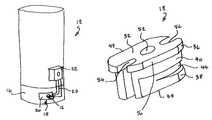
- FIG. 1illustrates the sealing mechanism of the present invention in place on a water heater having a fully enclosed combustion chamber
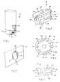
- FIG. 2is an enlarged perspective view of opening formed in the access panel configured for receipt of the grommet component of the present invention
- FIG. 3is an enlarged perspective view of the grommet component of the present invention.
- FIG. 4is a bottom plan view of the grommet component shown in FIG. 3;
- FIG. 5is a side elevation of the grommet component shown in FIGS. 3 and 4.
- the present inventionprovides a sealing mechanism for enabling various conduits to be extended through the vapor barrier formed about a combustion chamber of an appliance such as a water heater.
- the sealing mechanismensures that the isolation of the combustion chamber is not compromised by the routing of the conduits through the vapor barrier and that the incursion of flammable vapors there into or the propagation of flame therefrom is effectively prevented.
- FIG. 1generally illustrates a water heater 12 in which the sealing mechanism 14 of the present invention is employed.
- the water heaterhas a sealed combustion chamber wherein a barrier 16 is fitted about the base of the water heater to prevent the incursion of flammable vapors into the combustion chamber and the propagation of flame therefrom.
- the sealing mechanism of the present inventionconsists of the combination of a grommet component 18 and a specially configured opening formed in the barrier and may be formed in an access panel or door panel 20 fitted to such barrier.
- the door or panelprovides access to the various components that are situated within the combustion chamber including the burner, the pilot, the ignition system and any thermocouple or thermopile that may be employed.
- a control mechanismsuch as a gas valve 22 is shown attached to the exterior of the water heater from which conduits 24 extend into the combustion chamber. The control mechanism regulates the gas flowing to the burner to maintain the temperature of the water within a set range, and controls the lighting and operation of the pilot.
- conduits 24are shown extending from the gas valve into the interior of the combustion chamber.
- Such conduitsinclude the pilot gas supply line, a thermocouple and an ignitor wire.
- the conduitspenetrate the vapor barrier 16 through an opening formed in door panel 20 .
- the grommet component 18 that is received in such openingensures that the combustion chamber remains substantially sealed.
- FIG. 2is an enlarged perspective view of the circular opening 25 formed in access panel 20 .
- the openingis surrounded by a depressed rim 26 that extends into the combustion chamber and defines an inner surface that is perpendicular to the plane of the panel.
- Two diametrically opposed tabs 28extend inwardly from the inner edge of the depressed rim. The two tabs serve to truncate the circular opening to leave an elongated aperture 30 there between.
- FIG. 3is an enlarged perspective view of the grommet component 18 which is configured for receipt within the opening formed in the barrier material as is shown in FIG. 2 .
- the grommet componenthas a proximal end 32 and a distal end 34 with three distinctly configured sections there between including proximal section 36 , a distal section 38 and an intermediate section 40 .
- the distal section 38has a cross-section corresponding to a truncated circle which matches the dimensions of the aperture 30 defined in opening 25 .
- the intermediate section 40has a circular cross-section having a diameter which matches the diameter of the rim surface 26 of opening 24 .
- the distal facing surfaces 42 of the intermediate section that are exposed by the truncation of the distal sectiondefine a flange that extends into grooves 44 formed in the side of the distal section.
- the side view of FIG. 5illustrates the tapered shape of such grooves wherein the narrower end approximates the thickness of tabs 28 .
- the thickness of the intermediate sectioncorresponds to the depth of the depressed rim 26 .
- the proximal section 36has a cross-section that is larger than that of the intermediate section to form a flange surface 46 that completely surrounds the intermediate section.
- the proximal sectionagain defines a truncated circle in which edges 48 and 50 are parallel to one another.
- Three perforations 52 , 54 , 56extend through the grommet component the particular embodiment that is illustrated. Perforations 54 and 56 are formed on the edge of the grommet while perforation 52 is centrally located.
- the grommet component 18is preferably formed of powdered metal.
- powdered metal technologyrequires the metal powder to first be compressed and then sintered in an atmosphere controlled furnace at high temperature in order to bond the powder. The resulting mass is then machined to the tolerances required in this application.
- Powdered aluminumis the preferred metal for forming the grommet component.
- powdered zinc or steelmay be used.
- die cast aluminum or zincmay be used as well as machined aluminum or steel.
- molded high temperature plasticsmay also be a viable alternative for some applications.
- the dimensions of the cooperating surfaces of the opening 25 in the barrier panel and the grommet componentmust be within 0.007′′ of one another, while the inner diameters of the apertures 52 , 54 , 56 must be within 0.006′′ of the outside diameters of the conduits that are to be accommodated therein.
- the various conduits 24 that are to extend into the combustion chamberare threaded through the perforations 52 , 54 , 56 in the grommet component 18 and the opening 25 in the barrier panel 20 .
- the respective ends of such conduitsmay then be appropriately fitted to the controller 22 and to positions within the combustion chamber after which the access panel is fitted to the barrier 20 .
- the grommet componentis then advanced along the conduits into the opening formed in the barrier panel.
- the grommet componentis inserted until flange surfaces 42 make contact with the tabs. Subsequent rotation of the grommet component causes the tabs to enter into grooves 44 and prevent retraction of the grommet component.
Landscapes
- Engineering & Computer Science (AREA)
- General Engineering & Computer Science (AREA)
- Mechanical Engineering (AREA)
- Physics & Mathematics (AREA)
- Thermal Sciences (AREA)
- Chemical & Material Sciences (AREA)
- Combustion & Propulsion (AREA)
- Feeding And Controlling Fuel (AREA)
- Installation Of Indoor Wiring (AREA)
- Gasket Seals (AREA)
- Connector Housings Or Holding Contact Members (AREA)
Abstract
Description
Claims (14)
Priority Applications (6)
| Application Number | Priority Date | Filing Date | Title |
|---|---|---|---|
| US09/672,325US6484358B1 (en) | 2000-09-28 | 2000-09-28 | Flame proof sealing mechanism |
| DE60130566TDE60130566T2 (en) | 2000-09-28 | 2001-09-28 | FLAME-PROOF SEALING DEVICE |
| EP01975579AEP1320702B1 (en) | 2000-09-28 | 2001-09-28 | Flame proof sealing mechanism |
| PCT/US2001/030530WO2002027230A2 (en) | 2000-09-28 | 2001-09-28 | Flame proof sealing mechanism |
| ES01975579TES2291357T3 (en) | 2000-09-28 | 2001-09-28 | FIRE PROOF SEALING MECHANISM. |
| AU2001294893AAU2001294893A1 (en) | 2000-09-28 | 2001-09-28 | Flame proof sealing mechanism |
Applications Claiming Priority (1)
| Application Number | Priority Date | Filing Date | Title |
|---|---|---|---|
| US09/672,325US6484358B1 (en) | 2000-09-28 | 2000-09-28 | Flame proof sealing mechanism |
Publications (1)
| Publication Number | Publication Date |
|---|---|
| US6484358B1true US6484358B1 (en) | 2002-11-26 |
Family
ID=24698076
Family Applications (1)
| Application Number | Title | Priority Date | Filing Date |
|---|---|---|---|
| US09/672,325Expired - Fee RelatedUS6484358B1 (en) | 2000-09-28 | 2000-09-28 | Flame proof sealing mechanism |
Country Status (6)
| Country | Link |
|---|---|
| US (1) | US6484358B1 (en) |
| EP (1) | EP1320702B1 (en) |
| AU (1) | AU2001294893A1 (en) |
| DE (1) | DE60130566T2 (en) |
| ES (1) | ES2291357T3 (en) |
| WO (1) | WO2002027230A2 (en) |
Cited By (14)
| Publication number | Priority date | Publication date | Assignee | Title |
|---|---|---|---|---|
| US8692123B2 (en) | 2011-06-21 | 2014-04-08 | Sunbeam Products, Inc. | Electrical device with power cord insert |
| US8944718B2 (en) | 2010-09-23 | 2015-02-03 | C-Flex Bearing Co., Inc. | Clamping bushing |
| US20150316203A1 (en)* | 2014-04-30 | 2015-11-05 | Cooper Technologies Company | Trapeze hanger system including twist-locking fitting |
| US9347213B1 (en) | 2014-11-14 | 2016-05-24 | Cooper Technologies Company | Fitting for channel framing |
| US9453592B2 (en) | 2013-03-14 | 2016-09-27 | Cooper Technologies Company | Fitting including clip for channel framing |
| US9546744B2 (en) | 2014-05-02 | 2017-01-17 | Cooper Technologies Company | Conduit clamp for strut channel |
| US9574589B2 (en) | 2014-04-30 | 2017-02-21 | Cooper Technologies Company | Trapeze hanger system including trapeze hanger fitting |
| US9683590B2 (en) | 2014-05-02 | 2017-06-20 | Cooper Technologies Company | Strut system and strut fitting therefor |
| US9790980B2 (en) | 2013-12-23 | 2017-10-17 | Cooper Technologies Company | Fastener nut for channel framing |
| US9926957B2 (en) | 2014-11-14 | 2018-03-27 | Cooper Technologies Company | Fitting for strut channel |
| US9982695B2 (en) | 2014-11-14 | 2018-05-29 | Cooper Technologies Company | Fitting for strut channel |
| US10100861B2 (en) | 2014-11-14 | 2018-10-16 | Cooper Technologies Company | Beam clamp for strut channel |
| US10260777B2 (en)* | 2017-08-15 | 2019-04-16 | Haier Us Appliance Solutions, Inc. | Gas fueled water heater appliance having a temperature control switch |
| CN115117578A (en)* | 2022-07-29 | 2022-09-27 | 厦门海辰新能源科技有限公司 | Sealing nail and application thereof, sealing assembly and application thereof and sealing method |
Citations (16)
| Publication number | Priority date | Publication date | Assignee | Title |
|---|---|---|---|---|
| US3506999A (en)* | 1968-08-05 | 1970-04-21 | Mc Donnell Douglas Corp | Fair-lead grommet |
| US3991446A (en)* | 1975-04-30 | 1976-11-16 | I-T-E Imperial Corporation | One piece knock-out plug |
| US4216930A (en)* | 1978-08-24 | 1980-08-12 | Amp Incorporated | Strain relief |
| US4354651A (en)* | 1978-05-24 | 1982-10-19 | Hans Simon | Cable grommet with tension relief |
| US4474489A (en)* | 1982-03-29 | 1984-10-02 | Hans Simon | Tension-relieving cable duct |
| US4940042A (en) | 1988-08-24 | 1990-07-10 | Mor-Flo Industries, Inc. | System and apparatus for venting water heater |
| US5170017A (en)* | 1991-02-15 | 1992-12-08 | Augat Inc. | Connector and method for sealed pass-through of insulated electrical conductors |
| US5188324A (en)* | 1992-04-16 | 1993-02-23 | Digital Equipment Corporation | Self-retaining mounting block |
| US5341767A (en) | 1993-05-05 | 1994-08-30 | Aos Holding Company | Combustion air inlet diverter plate for a water heater |
| US5613406A (en)* | 1995-10-26 | 1997-03-25 | Teleflex Incorporated | Rotating slide-n-snap |
| US5857780A (en)* | 1997-05-22 | 1999-01-12 | Emerson Electric Co. | Self-aligning/rigid spherical bearing assembly |
| US5918591A (en) | 1997-05-01 | 1999-07-06 | Vollmar; Tad F. | Gas hot water heater safety shield |
| US5941200A (en) | 1998-01-07 | 1999-08-24 | The Water Heater Industry Joint Research And Development Consortium | Gas-fired water heater having plate-mounted removable bottom end burner and pilot assembly |
| US6019069A (en) | 1991-12-30 | 2000-02-01 | Bowin Technology Pty. Ltd. | Gas-fired heaters with burners which operate without secondary air and have a substantially sealed combustion chamber |
| US6074200A (en) | 1998-01-20 | 2000-06-13 | Gas Research Institute | Burner apparatus having an air dam and mixer tube |
| US6109216A (en) | 1999-07-22 | 2000-08-29 | Aos Holding Company | Flammable vapor resistant water heater |
Family Cites Families (3)
| Publication number | Priority date | Publication date | Assignee | Title |
|---|---|---|---|---|
| US3091795A (en)* | 1960-08-05 | 1963-06-04 | Gilbert G Budwig | Grommet |
| EP0580130A1 (en)* | 1992-07-21 | 1994-01-26 | Ichikoh Industries Limited | Lead-wire grommet |
| DE19533920A1 (en)* | 1995-09-13 | 1997-03-20 | Rasmussen Gmbh | Connection hose fastening device |
- 2000
- 2000-09-28USUS09/672,325patent/US6484358B1/ennot_activeExpired - Fee Related
- 2001
- 2001-09-28DEDE60130566Tpatent/DE60130566T2/ennot_activeExpired - Fee Related
- 2001-09-28AUAU2001294893Apatent/AU2001294893A1/ennot_activeAbandoned
- 2001-09-28EPEP01975579Apatent/EP1320702B1/ennot_activeExpired - Lifetime
- 2001-09-28WOPCT/US2001/030530patent/WO2002027230A2/enactiveIP Right Grant
- 2001-09-28ESES01975579Tpatent/ES2291357T3/ennot_activeExpired - Lifetime
Patent Citations (16)
| Publication number | Priority date | Publication date | Assignee | Title |
|---|---|---|---|---|
| US3506999A (en)* | 1968-08-05 | 1970-04-21 | Mc Donnell Douglas Corp | Fair-lead grommet |
| US3991446A (en)* | 1975-04-30 | 1976-11-16 | I-T-E Imperial Corporation | One piece knock-out plug |
| US4354651A (en)* | 1978-05-24 | 1982-10-19 | Hans Simon | Cable grommet with tension relief |
| US4216930A (en)* | 1978-08-24 | 1980-08-12 | Amp Incorporated | Strain relief |
| US4474489A (en)* | 1982-03-29 | 1984-10-02 | Hans Simon | Tension-relieving cable duct |
| US4940042A (en) | 1988-08-24 | 1990-07-10 | Mor-Flo Industries, Inc. | System and apparatus for venting water heater |
| US5170017A (en)* | 1991-02-15 | 1992-12-08 | Augat Inc. | Connector and method for sealed pass-through of insulated electrical conductors |
| US6019069A (en) | 1991-12-30 | 2000-02-01 | Bowin Technology Pty. Ltd. | Gas-fired heaters with burners which operate without secondary air and have a substantially sealed combustion chamber |
| US5188324A (en)* | 1992-04-16 | 1993-02-23 | Digital Equipment Corporation | Self-retaining mounting block |
| US5341767A (en) | 1993-05-05 | 1994-08-30 | Aos Holding Company | Combustion air inlet diverter plate for a water heater |
| US5613406A (en)* | 1995-10-26 | 1997-03-25 | Teleflex Incorporated | Rotating slide-n-snap |
| US5918591A (en) | 1997-05-01 | 1999-07-06 | Vollmar; Tad F. | Gas hot water heater safety shield |
| US5857780A (en)* | 1997-05-22 | 1999-01-12 | Emerson Electric Co. | Self-aligning/rigid spherical bearing assembly |
| US5941200A (en) | 1998-01-07 | 1999-08-24 | The Water Heater Industry Joint Research And Development Consortium | Gas-fired water heater having plate-mounted removable bottom end burner and pilot assembly |
| US6074200A (en) | 1998-01-20 | 2000-06-13 | Gas Research Institute | Burner apparatus having an air dam and mixer tube |
| US6109216A (en) | 1999-07-22 | 2000-08-29 | Aos Holding Company | Flammable vapor resistant water heater |
Cited By (27)
| Publication number | Priority date | Publication date | Assignee | Title |
|---|---|---|---|---|
| US8944718B2 (en) | 2010-09-23 | 2015-02-03 | C-Flex Bearing Co., Inc. | Clamping bushing |
| US8692123B2 (en) | 2011-06-21 | 2014-04-08 | Sunbeam Products, Inc. | Electrical device with power cord insert |
| US9470339B2 (en) | 2013-03-14 | 2016-10-18 | Cooper Technologies Company | Fitting for connecting two pieces of channel framing to one another |
| US10619791B2 (en) | 2013-03-14 | 2020-04-14 | Eaton Intelligent Power Limited | Channel framing with additional functional side |
| US9453592B2 (en) | 2013-03-14 | 2016-09-27 | Cooper Technologies Company | Fitting including clip for channel framing |
| US9982837B2 (en) | 2013-03-14 | 2018-05-29 | Cooper Technologies Company | Fitting including clip for channel framing |
| US9587767B2 (en) | 2013-03-14 | 2017-03-07 | Cooper Technology Company | Fitting for trapeze hanger |
| US9651171B2 (en) | 2013-03-14 | 2017-05-16 | Cooper Technologies Company | Nut-washer assembly for channel framing |
| US9746105B2 (en) | 2013-03-14 | 2017-08-29 | Cooper Technologies Company | Conduit clamp for channel framing |
| US9790980B2 (en) | 2013-12-23 | 2017-10-17 | Cooper Technologies Company | Fastener nut for channel framing |
| US9458952B2 (en)* | 2014-04-30 | 2016-10-04 | Cooper Technologies Company | Trapeze hanger system including twist-locking fitting |
| US10012255B2 (en) | 2014-04-30 | 2018-07-03 | Cooper Technologies Company | Trapeze hanger system including trapeze hanger fitting |
| US9574589B2 (en) | 2014-04-30 | 2017-02-21 | Cooper Technologies Company | Trapeze hanger system including trapeze hanger fitting |
| US20150316203A1 (en)* | 2014-04-30 | 2015-11-05 | Cooper Technologies Company | Trapeze hanger system including twist-locking fitting |
| US9732887B2 (en) | 2014-04-30 | 2017-08-15 | Cooper Technologies Company | Trapeze hanger system including twist-locking fitting |
| US9683590B2 (en) | 2014-05-02 | 2017-06-20 | Cooper Technologies Company | Strut system and strut fitting therefor |
| US9989169B2 (en) | 2014-05-02 | 2018-06-05 | Cooper Technologies Company | Conduit clamp for strut channel |
| US9546744B2 (en) | 2014-05-02 | 2017-01-17 | Cooper Technologies Company | Conduit clamp for strut channel |
| US9926957B2 (en) | 2014-11-14 | 2018-03-27 | Cooper Technologies Company | Fitting for strut channel |
| US9580900B2 (en) | 2014-11-14 | 2017-02-28 | Cooper Technologies Company | Fitting for channel framing |
| US9982695B2 (en) | 2014-11-14 | 2018-05-29 | Cooper Technologies Company | Fitting for strut channel |
| US10100861B2 (en) | 2014-11-14 | 2018-10-16 | Cooper Technologies Company | Beam clamp for strut channel |
| US10161127B2 (en) | 2014-11-14 | 2018-12-25 | Cooper Technologies Company | Fitting for channel framing |
| US9347213B1 (en) | 2014-11-14 | 2016-05-24 | Cooper Technologies Company | Fitting for channel framing |
| US10260777B2 (en)* | 2017-08-15 | 2019-04-16 | Haier Us Appliance Solutions, Inc. | Gas fueled water heater appliance having a temperature control switch |
| CN115117578A (en)* | 2022-07-29 | 2022-09-27 | 厦门海辰新能源科技有限公司 | Sealing nail and application thereof, sealing assembly and application thereof and sealing method |
| CN115117578B (en)* | 2022-07-29 | 2023-09-08 | 厦门海辰储能科技股份有限公司 | Sealing nail and application thereof, sealing assembly and application and sealing method thereof |
Also Published As
| Publication number | Publication date |
|---|---|
| DE60130566T2 (en) | 2008-06-12 |
| ES2291357T3 (en) | 2008-03-01 |
| WO2002027230A3 (en) | 2002-06-13 |
| DE60130566D1 (en) | 2007-10-31 |
| EP1320702A2 (en) | 2003-06-25 |
| WO2002027230A2 (en) | 2002-04-04 |
| AU2001294893A1 (en) | 2002-04-08 |
| EP1320702B1 (en) | 2007-09-19 |
Similar Documents
| Publication | Publication Date | Title |
|---|---|---|
| US6484358B1 (en) | Flame proof sealing mechanism | |
| JPS63282422A (en) | Carburetion type burner | |
| WO2001046625A1 (en) | An adjustable mount for a gas control valve of a water heater | |
| CA2234388A1 (en) | A gas appliance for heating fluids | |
| EP0809072A2 (en) | Structure for supply of fuel and pilot air | |
| US2250045A (en) | Thermostatic lock fob the closures | |
| US6446582B1 (en) | Fuel feedline and vapor barrier assembly | |
| EP3524882A1 (en) | Heat cell with metallic insulation ring | |
| CA2276702C (en) | A pilot gas burner | |
| US2486018A (en) | Fluid fuel burner having laterally directed flame ports | |
| KR100303288B1 (en) | Cooking stove burner | |
| KR200155549Y1 (en) | Gas stove ceramic grill burner | |
| JP3916108B2 (en) | Burner device with fuel preheating means | |
| CA1322153C (en) | Combustion heating apparatus | |
| EP1293720B1 (en) | Cover assembly for sealing openings in an outer pipe part and an inner pipe part | |
| EP3099977A1 (en) | Igniter for a gas burner assembly and cooking appliance having the same | |
| CN222597801U (en) | Gas stove | |
| JPS6137981Y2 (en) | ||
| WO1999023420A1 (en) | Baffle ignitor assembly | |
| JP3863821B2 (en) | Combustion device | |
| KR0135828Y1 (en) | Pilot burner assembly structure of a gas range | |
| KR950008613B1 (en) | Gas burner | |
| JPS6126756Y2 (en) | ||
| JPS6146326Y2 (en) | ||
| KR0133326B1 (en) | Exhaust equipment of a rotary heater |
Legal Events
| Date | Code | Title | Description |
|---|---|---|---|
| AS | Assignment | Owner name:INVENSYS ROBERTSHAW CONTROLS COMPANY, MASSACHUSETT Free format text:ASSIGNMENT OF ASSIGNORS INTEREST;ASSIGNORS:DUONG, THACH;BOEHNLEIN, CONRAD;REEL/FRAME:011357/0056 Effective date:20001101 | |
| FEPP | Fee payment procedure | Free format text:PAYOR NUMBER ASSIGNED (ORIGINAL EVENT CODE: ASPN); ENTITY STATUS OF PATENT OWNER: LARGE ENTITY | |
| AS | Assignment | Owner name:DEUTSCHE BANK AG, LONDON, UNITED KINGDOM Free format text:SECURITY INTEREST;ASSIGNOR:ROBERTSHAW CONTROLS COMPANY;REEL/FRAME:015271/0850 Effective date:20040401 | |
| AS | Assignment | Owner name:ROBERTSHAW CONTROLS COMPANY, VIRGINIA Free format text:CHANGE OF NAME;ASSIGNOR:INVENSYS ROBERTSHAW CONTROLS COMPANY;REEL/FRAME:014523/0065 Effective date:20040406 | |
| FPAY | Fee payment | Year of fee payment:4 | |
| AS | Assignment | Owner name:DEUTSCHE BANK AG, LONDON BRANCH,UNITED KINGDOM Free format text:SECURITY AGREEMENT;ASSIGNOR:ROBERTSHAW CONTROLS COMPANY;REEL/FRAME:017921/0846 Effective date:20060713 Owner name:DEUTSCHE BANK AG, LONDON BRANCH, UNITED KINGDOM Free format text:SECURITY AGREEMENT;ASSIGNOR:ROBERTSHAW CONTROLS COMPANY;REEL/FRAME:017921/0846 Effective date:20060713 | |
| AS | Assignment | Owner name:ROBERTSHAW CONTROLS COMPANY, VIRGINIA Free format text:RELEASE AND TERMINATION OF SECURITY INTEREST;ASSIGNOR:DEUTSCHE BANK AG, LONDON BRANCH;REEL/FRAME:018087/0258 Effective date:20060713 | |
| REMI | Maintenance fee reminder mailed | ||
| LAPS | Lapse for failure to pay maintenance fees | ||
| STCH | Information on status: patent discontinuation | Free format text:PATENT EXPIRED DUE TO NONPAYMENT OF MAINTENANCE FEES UNDER 37 CFR 1.362 | |
| FP | Lapsed due to failure to pay maintenance fee | Effective date:20101126 |