US6483898B2 - System and method for providing visual indication of caller and telephony platform information on customer premises equipment - Google Patents
System and method for providing visual indication of caller and telephony platform information on customer premises equipmentDownload PDFInfo
- Publication number
- US6483898B2 US6483898B2US09/151,860US15186098AUS6483898B2US 6483898 B2US6483898 B2US 6483898B2US 15186098 AUS15186098 AUS 15186098AUS 6483898 B2US6483898 B2US 6483898B2
- Authority
- US
- United States
- Prior art keywords
- event
- message
- identifier
- accessory
- event message
- Prior art date
- Legal status (The legal status is an assumption and is not a legal conclusion. Google has not performed a legal analysis and makes no representation as to the accuracy of the status listed.)
- Expired - Fee Related
Links
Images


Classifications
- H—ELECTRICITY
- H04—ELECTRIC COMMUNICATION TECHNIQUE
- H04M—TELEPHONIC COMMUNICATION
- H04M1/00—Substation equipment, e.g. for use by subscribers
- H04M1/247—Telephone sets including user guidance or feature selection means facilitating their use
- H04M1/2478—Telephone terminals specially adapted for non-voice services, e.g. email, internet access
- H—ELECTRICITY
- H04—ELECTRIC COMMUNICATION TECHNIQUE
- H04M—TELEPHONIC COMMUNICATION
- H04M1/00—Substation equipment, e.g. for use by subscribers
- H04M1/247—Telephone sets including user guidance or feature selection means facilitating their use
- H—ELECTRICITY
- H04—ELECTRIC COMMUNICATION TECHNIQUE
- H04M—TELEPHONIC COMMUNICATION
- H04M1/00—Substation equipment, e.g. for use by subscribers
- H04M1/57—Arrangements for indicating or recording the number of the calling subscriber at the called subscriber's set
- H—ELECTRICITY
- H04—ELECTRIC COMMUNICATION TECHNIQUE
- H04M—TELEPHONIC COMMUNICATION
- H04M3/00—Automatic or semi-automatic exchanges
- H04M3/42—Systems providing special services or facilities to subscribers
- H04M3/48—Arrangements for recalling a calling subscriber when the wanted subscriber ceases to be busy
- H—ELECTRICITY
- H04—ELECTRIC COMMUNICATION TECHNIQUE
- H04M—TELEPHONIC COMMUNICATION
- H04M3/00—Automatic or semi-automatic exchanges
- H04M3/42—Systems providing special services or facilities to subscribers
- H04M3/50—Centralised arrangements for answering calls; Centralised arrangements for recording messages for absent or busy subscribers ; Centralised arrangements for recording messages
- H04M3/53—Centralised arrangements for recording incoming messages, i.e. mailbox systems
- H04M3/537—Arrangements for indicating the presence of a recorded message, whereby the presence information might include a preview or summary of the message
- H—ELECTRICITY
- H04—ELECTRIC COMMUNICATION TECHNIQUE
- H04Q—SELECTING
- H04Q3/00—Selecting arrangements
- H04Q3/72—Finding out and indicating number of calling subscriber
- H—ELECTRICITY
- H04—ELECTRIC COMMUNICATION TECHNIQUE
- H04Q—SELECTING
- H04Q2213/00—Indexing scheme relating to selecting arrangements in general and for multiplex systems
- H04Q2213/1309—Apparatus individually associated with a subscriber line, line circuits
- H—ELECTRICITY
- H04—ELECTRIC COMMUNICATION TECHNIQUE
- H04Q—SELECTING
- H04Q2213/00—Indexing scheme relating to selecting arrangements in general and for multiplex systems
- H04Q2213/13175—Graphical user interface [GUI], WWW interface, visual indication
- H—ELECTRICITY
- H04—ELECTRIC COMMUNICATION TECHNIQUE
- H04Q—SELECTING
- H04Q2213/00—Indexing scheme relating to selecting arrangements in general and for multiplex systems
- H04Q2213/13376—Information service, downloading of information, 0800/0900 services
- H—ELECTRICITY
- H04—ELECTRIC COMMUNICATION TECHNIQUE
- H04Q—SELECTING
- H04Q2213/00—Indexing scheme relating to selecting arrangements in general and for multiplex systems
- H04Q2213/13377—Recorded announcement
Definitions
- the present inventionrelates to telecommunications services, and more particularly to a method and system for providing information about telecommunications services.
- Telecommunications service providersoffer a variety of accessory telephone services to enhance the basic capability of connecting callers on the system. Such services include messaging services, call waiting, caller identification, electronic mail (email), facsimile, etc. Users (i.e. customers of the telecommunications service providers) typically subscribe to such telephone services and use the services from a plain old telephone set.
- the telephone services offered by the telecommunications service providersmay replace similar services offered by other sources that may require the use of special equipment.
- voice mailallows users to communicate audio messages in a manner similar to written communications.
- voice mail systemsusers receive messages in voice mailboxes that allow a user to receive, edit and forward messages to one or more mailboxes within a voice mail system.
- Voice mailmay be provided within a private switching system such as a private branch exchange (PBX), or it may be offered as an auxiliary service by telecommunications service providers over the general switched telephone network (GSTN).
- PBXprivate branch exchange
- GSTNgeneral switched telephone network
- Voice mail systems operating within a PBXare private systems that are typically used only by users that work for a common organization in one or more buildings. Such private systems may require that all devices that connect to it be of selected types.
- One advantage of messaging services provided by telecommunications providersis that it makes voice mail available to all customers and not just to organizations or businesses using a private voice mail system.
- Another advantage of using messaging services provided by telecommunications providersis that many types of telecommunications devices may be used to access the services.
- One problem with using messaging systems such as voice mailis that the systems lack the visual indication that message machines provide.
- a usermay have many messages waiting to be heard at any given time. To get through all of them, the user must listen to or skip through each one sequentially. Because messages are stored in the order received, the most important messages may be separated by many unimportant messages.
- the voice mail systemsalso lack a way of searching through the messages for the most important or relevant messages. Where a telephone or voice mail is shared by several users, each user may have to listen to, or skip over messages that have been left for someone else. Currently, many voice mail systems remove any new message indications from messages that have been skipped over. Other users may not receive an indication that there are messages waiting for them.
- message machines and voice mail servicesare shared by all of the members of the family. If a teenage member of the family retrieves his messages from the voice mail service, each message must be listened to or skipped over in sequence before arriving to the message directed to him. As the messages that aren't for the teenage member are listened to or skipped over, the new message indication is eliminated. Thus, the other members of the family would not know that they have messages.
- Call waiting with name and caller identificationis telephone services that provide a user with the identification or the name of callers that have attempted to call a telephone having a display.
- the identifications(telephone numbers or names) are left on the display until cleared by the user.
- One problem with the call waiting with name and caller identification servicesis that the information provided is limited to the name or identification of a party that tried to call the user.
- the caller identification servicesdo not provide any other information such as whether a caller left a message in voice mail.
- FIG. 1is a block diagram of a telecommunications system of the type in which the present invention finds particular use;
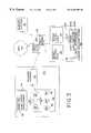
- FIG. 2Ashows examples of connections for communicating information-receiving events in the telecommunications system in FIG. 1;
- FIG. 2Bshows examples of connections for communicating information-retrieving events in the telecommunications system in FIG. 1;
- FIG. 3is a block diagram of the customer premises equipment of FIG. 1 according to one embodiment of the present invention.
- FIG. 4is a block diagram of the customer premises equipment of FIG. 1 according to an alternative embodiment of the present invention.
- FIG. 5is a block diagram of the record manager in the customer premises equipment of FIG. 4 according to an alternative embodiment of the present invention.
- FIG. 1is a block diagram of a telecommunications network of the type in which the present invention finds particular use.
- the network in FIG. 1includes a first Customer Premises Equipment (CPE) 10 a , a second CPE 10 b , a first central office switch 20 a , a second central office switch 20 b , first and second supplemental service networks 50 a, b and a telephony platform 80 .
- the network in FIG. 1may be used to receive telephony platform information for a user of the first CPE 10 a as telephony platform resources are used. The information is processed and maintained for easy access and display on the CPE 10 a .
- the telephony platform servicesthat are the objects of the information, such as voice mail messages, email or facsimiles, may be efficiently retrieved using the CPE 10 a.
- the central office switches 20 a, bprovide the CPE's 10 a, b, and the telephony platform 80 with access to the general switched telephone network (GSTN).
- the first central office switch 20 aprovides call routing for the CPE 10 a and other customer premises equipment in the service area in which the first central office switch 20 a operates.
- the second central office switch 20 bprovides call routing services to the second CPE 10 b and to other customer premises equipment in a service area in which the second central office switch 20 b operates.
- the first central office switch 20 ais connected to the second central office switch 20 b , and to other central office switches via interoffice trunking systems 14 .
- the interoffice trunking system 14 and the central office switches 20 a, bimplement a signal switching protocol to make telecommunications connections.
- SS7Signaling System #7
- the telephony platform 80may provide any accessory telecommunications service that may enhance the options available to the users of telecommunications services.
- the telephony platform 80may include a messaging platform such as, voice mail.
- Other applications that may be included in a telephony platform 80are electronic mail, facsimile, etc.
- a user at the first CPE 10 a or at the second CPE 10 bmay access the services provided by the telephony platform 80 by dialing the service and connecting through the central office switch 20 a.
- the supplemental service networks 50 a, bmay be used to provide information regarding telecommunication services available to and used by the users at the first CPE 10 a and the second CPE 10 b , respectively.
- the supplemental service networks 50 a, bmay include an event processor and a customer information database (described below with reference to FIGS. 2 - 4 ).
- the supplemental service networks 50 a, breceive events, or triggers which may include requests for information from the central office switches 20 a, b .
- the event or triggermay be sensed by a pattern in a dialing sequence in the central office switches 20 a, b.
- the event processorperforms the functions required to respond to the event and retrieves any customer information required from the customer information database.
- the customer information in the supplemental service network 50 a, bmay include basic customer usage information and information regarding the telephony services to which the user may subscribe. It is to be understood by one of skill in the art that the event processor and the customer information database may be implemented anywhere in the GSTN. In addition, it is to be understood by one of ordinary skill in the art that the connections shown between the supplemental service network 50 a and 50 b and the central office switches 20 a and 20 b , respectively, are purely for illustrative purposes. Components and functions of the supplemental service network 50 a, b may be implemented anywhere in the GSTN.
- the central office switches 20 a, bmay be provided with any functions necessary for accessing the event processor and the customer information database or any other component in the supplemental service network 50 a, b.
- the supplemental service network 50 a, bmay include the Advanced Intelligent Network (AIN).
- AINAdvanced Intelligent Network
- One advantage of using the AINis that it is widely available and used by telecommunications service providers.
- the AINis also well suited for use in a multi-vendor environment in which equipment may be manufactured and used by different vendors.
- a switched-based networkmay be used in which the functions of the supplementary service network 50 a, b are performed in a local switch.
- the CPE 10 a and the CPE 10 bmay include any telecommunications device that communicates via the GSTN.
- the CPE 10 ais preferably a telephone having a display device 15 a .
- the display device 15 aprovides information about the telecommunications services that are used by the user.
- One advantage of the present inventionis that the display device 15 a may be used to display a first message and a second message.
- the first messageincludes a caller-identifier, which may include the name of a caller that attempted to place a call to the CPE 10 a .
- the second event messagemay be an information indicator 16 that identifies any caller that left a message in voice mail.
- the information indicator 16may be an asterisk or other mark or icon placed next to the identifier of a caller in the list in the display device 15 b to indicate that the caller left a message in the user's voice mail.
- the information indicator 16may be used to provide information about a call that relates to any other accessory telephone service available to the user of the first CPE 10 a .
- the information indicator 16may be used to inform the user that the corresponding caller left a fax or an email in the mailbox.
- the CPE 10 amay attach to a computer or a facsimile machine.
- the CPE 10 bmay also include a display device 15 b and the information indicator 16 .
- the CPE's 10 a, bmay also include special function keys that combine with the display devices 15 a, b to provide additional features.
- a scroll keymay be provided to allow user to scroll through the list of caller identifiers listed in the display device.
- Another keymay be provided to allow the user to connect to the voice mail system with a request for a specific message.
- the voice mail systemmay retrieve a message left by the caller identified by a selector in the display device.
- One advantage of the CPE 10 ais that it includes an enter key (discussed below) for highlighting and selecting entries in the list on the display device, and a retrieve key (discussed below) for initiating a retrieval of the services indicated by the entry. For example, the user may enable several different entries by scrolling through the entries indicating that voice mail messages were left, highlighting and selecting the entries by hitting the Enter key, and initiating a retrieval of the voice mail messages by hitting the Retrieve key.
- the block diagram in FIG. 2Ashows the telecommunications network of FIG. 1 and examples of connections and messages for receiving telephony platform information according to a preferred embodiment of the present invention.
- the flow of messages and eventsrelate to an attempt by the second CPE 10 b (hereinafter “calling party”) to make a telephone connection, or a telephone call to the first CPE 10 a (hereinafter the “called party”).
- the call madeis a voice call by a calling party using the calling party CPE 10 b .
- any type of telecommunications connection over the GSTNmay be used and that any type of accessory service may be used as well.
- the supplemental service network 50 aincludes a customer information database 54 for storing customer identifiers, or data base elements containing information about customers.
- the customer identifiersmay be used as a called party identifier that may further include the name of the called party and the telephone number of the called party CPE 10 a.
- central office switches 20 a,b in FIG. 2is one illustrative example of how communication between the CPE's 10 a, b, the supplemental service network 50 a, b, and the telephony platform 80 may be accomplished.
- the CPE's 10 a, bmay connect to supplemental service network 50 components via another-central office switch 20 .
- the calling partyinitiates a call by picking up the receiver set on the calling party CPE 10 b and dialing the called party telephone number causing a telephone call initiation 100 .
- the second central office switch 20 breceives the telephone call initiation 100 , it completes the connection to the called party CPE 10 a which signals to the called party that an telephone call has been initiated.
- a termination attempt trigger 102occurs.
- the callis then suspended pending information from the supplemental service network 50 a .
- the supplemental service network 50 areceives the termination attempt trigger 102 at the event processor 52 along with information about the connection being attempted.
- the connection informationmay include the calling party telephone number, the calling party name, the called party telephone number and the called party name.
- the event processor 52uses the connection information to obtain customer information about the called party at the called party CPE 10 a from the customer information database 54 .
- the customer informationmay include supplemental service instructions to the central office switch 20 a during an attempted call to the called party CPE 10 a .
- the event processor 52also creates and stores an event record 56 having a calling party telephone number, a called party telephone number, the time of the termination attempt and an event identifier.
- the event processor 52may carry out the supplemental service instructions or return the instructions to the central office switch 20 a in a response 106 message.
- the response message 106may be a message that responds to any request for information at the supplemental service network 50 a .
- the central office switch 20 asends a call attempt signal 101 to annunciate a call to the CPE 10 a and the CPE 10 a signals the user by ringing, or other means.
- the central office switch 20 amay carry out instructions that may require a GSTN connection such as call forwarding to another telephone or to a voice mail system.
- the instructionsmay also include simple tasks such as sending a message to the CPE 10 a during the call attempt signaling 101 .
- the called party 10 amay subscribe to, or use a feature known in the art as Caller Identification, or Caller ID.
- the caller ID serviceprovides the called party with the identification of the caller attempting the call.
- the identification of the callermay be in the form of a text string identifying the caller by name, for example, or the identification may be the calling party telephone number.
- the identification of the caller and any other information about the calling partymay be retrieved from the supplemental service network 50 b that serves the calling party.
- the event processor 52sends a first event message 104 to the called party CPE 10 a to provide the information regarding the termination attempt.
- the first event message 104includes the calling party identifier and the calling party telephone number.
- the first event message 104may also include the event identifier.
- the called party CPE 10 areceives the first event message 104 and displays the identification of the caller on the display device 15 a of the called party CPE 10 a during the signaling of the attempted call (e.g. during ringing).
- the information carried in the first event message 104is retained to inform the called party of the termination attempt while the CPE 10 a is ringing.
- the display that informs the called partyis described below with reference to FIGS. 3 and 4.
- the central office switch 20 asends a third event message, or a telephony platform request 108 to the telephony platform 80 , which may include a voice mail service.
- the telephony platform request 108includes the calling party telephone number, the called party telephone number, the time and the event identifier in the event record 56 for the termination attempt 102 .
- the calling party CPE 10 bis connected to the voice mail service on the telephony platform 80 over the necessary GSTN connections (e.g. via the first central office switch 20 a, or via other central office switches to which the telephony platform may connect).
- the calling party at the calling party CPE 10 beither leaves a voice mail message for the called party, or terminates the connection. If the calling party terminates the connection by hanging up the CPE 10 b before leaving a message, the event record 56 is retained in the customer information database 56 .
- the telephony platform 80sends an accessory event message 110 indicating the calling party telephone number, the called party telephone number, the time of the message and the accessory event identifier.
- the accessory event message 110is preferably communicated over a connection that is made between the telephony platform 80 and the supplementary service network 50 a .
- the connectionis made using X.25, TCP/IP or any other suitable protocol that facilitates communication between two network elements.
- the event identifier in the accessory event message 110may be the same as the original event identifier created for the termination attempt to provide a way of matching messages with telephony events.
- the event processor 52 in the supplemental service network 50 areceives the accessory event message 110 and compares the event identifier in the accessory event message 110 with the event identifier in the event record 56 . If a match is found, the event processor 52 sends a second event message 112 to the called party CPE 10 a .
- the second event message 112includes the calling party identifier and the information indicator 16 .
- the information indicator 16provides a visual indication that a voice mail message corresponding to the caller identified in the display was left by the calling party.
- the event processor 52sends the second event message with the event identifier.
- the called party CPE 10 areceives the message 112 and compares the event identifier to determine if it relates to a previously received message. If the event identifier relates to a previously received message, the information indicator 16 is attached to the calling party identifier of the calling party corresponding to the event identifier of the second event message 112 .
- One advantage of sending the event identifier to the called party CPE 10 a for processingis that it distributes the processing of the information to the CPE's. This may provide some flexibility in the manner in which the information is displayed or handled by the CPE.
- the supplemental service instructions on the response 106may include contingency instructions for the central office switch 20 a .
- the contingency instructionsmay include instructions to follow in case the called party has requested that calls to the called party CPE 10 a be re-directed (e.g. call forwarding).
- call forwardingis to connect the calling party to a voice mail service or to forward the call directly to voice mail without signaling the call to the called party CPE 10 a .
- Call attempts that are forwarded to a different CPE 10 a or to voice mailmay be handled in the same manner as described except that the actual attempt to connect to the CPE 10 a is never made.
- the block diagram in FIG. 2Bshows the telecommunications network of FIG. 1 and examples of connections and messages for retrieving the objects of the telephony platform services according to a preferred embodiment of the present invention.
- the flow of messages and eventsrelate to the retrieval of objects of the services provided by the telephony platform 80 .
- the objectis a voice mail message left from an attempted voice call by a calling party using the calling party CPE 10 b .
- any type of accessory servicemay be used as well.
- the display device 15 a of the CPE 10 aincludes a list of the callers that had attempted to call the called party CPE 10 a with visual indicators 16 left next to the callers that left voice mail messages.
- the user of the CPE 10 amay use the scroll keys on the CPE 10 a to scroll through the list to identify messages that are the more urgent callers, or if the user shares the use of the CPE 10 a with others, the user may scroll through the list to identify his or her calls.
- the usermay scroll through the list and select more than one entry in the list and, with one press of a key, make a request for the retrieval of all of the objects associated with each entry.
- the requestmay include different types objects. For example, in one request, a user may retrieve more than one mail message, email message and facsimile.
- the usermay scroll through and select multiple entries such as a first entry 19 and a second entry 21 .
- the usermay press a retrieve key, or a get key to retrieve the objects of the entries, which in the example below is voice mail messages.
- the CPE 10 aprepares and sends information request messages 105 to the supplemental service network 50 a for each entry selected.
- the information request message 105may include the calling party identifier and the event identifier.
- the supplemental service network 50 areceives the information request messages 105 and connects to the telephony platform 80 over an ISDN, TCP/IP or other suitable connection.
- the supplemental service network 50 acommunicates a telephony platform retrieve message 119 to request the voice mail message (or email, or facsimile) identified by the calling party identifier, although the event identifier may also be used.
- a separate telephony platform retrieve message 119is sent for each information request message 105 received from the CPE 10 a .
- the supplemental service network 50 amay package multiple requests from multiple information request messages 105 in one telephony platform retrieve message 119 .
- the telephony platform 80responds to the telephony platform retrieve message 119 by connecting to the CPE 10 a via a switch-based connection 123 .
- the supplemental service network 50 amay include an agent to facilitate the connection to the CPE 10 a by the telephony platform 80 .
- the supplemental service network 50 ais an Advanced Intelligent Network (AIN) using a Service Node/Intelligent Peripheral (SN/IP) as an agent to connect the telephony platform 80 to the CPE 10 a .
- SN/IPService Node/Intelligent Peripheral
- the telephony platform 80then sends a telephony platform object message 121 to the CPE 10 a .
- the telephony platform object message 121is the voice mail message or other service performed by the telephony platform 80 .
- the voice mail message in the telephony platform object messagemay be played to the user upon receipt at the CPE 10 a , or it may be stored in the CPE 10 a along with other messages for later use.
- An email messagemay be displayed on the display device 15 a, or it may be stored for later display or for sending to a personal computer or handheld computer. Facsimiles may be delivered and directed to a suitable output device (not shown), or stored for later use.
- FIG. 3shows a block diagram of the CPE 10 a of FIG. 1 according to a preferred embodiment of the present invention.
- the CPE 10 a in FIG. 3is a telephone with a display for displaying caller identifier information as part of the caller identifier (Caller ID) service provided by telecommunications service providers.
- the CPE 10 a in FIG. 3is a telephone with a display for displaying caller identifier information as part of the caller identifier (Caller ID) service provided by telecommunications service providers.
- the scroll keys 17 a-d , the enter key 18 b , the delete key 18 a and the retrieve key 18 cprovide the user with the ability to scroll through the lines in the display. These keys and function are described further with reference to FIG. 4 .
- the CPE 10 aconnects to the central office switch 20 a via the telephone system interface 116 .
- the telephone system interface 116includes the hardware and software structure for communicating with the central office switch 20 a .
- the telephone system interface 116may include the hardware and software that inputs and outputs telephony signals that carry dialing, call setup and call information.
- the telephone system interface 116may input and output signals to the telephone transmitter and receiver set (not shown) and to a ringer (not shown).
- the telephone system interface 116is well known in the art and therefore requires no further description.
- the supplemental service network 50includes the Advanced Intelligent Network (AIN) 150 .
- the AIN 150receives event messages from the central office switch 20 a that connects the AIN 150 to the GSTN 120 using a signal transfer point 122 .
- the AIN 150also includes a service node/intelligent peripheral (SN/IP) 157 for creating switch-based connections that may be a part of a service performed by the AIN 150 .
- SN/IPservice node/intelligent peripheral
- the service control point 154analyzes the number sequences when a number is dialed to the central office switch and forms event messages.
- the event messagesare sent to the AIN 150 to determine whether the called party uses accessory services and, if so, the instructions that are to be followed in accordance with the accessory services.
- the AIN 150includes a service switching point 152 and a service control point 154 .
- the service switching point 152may include the event processor 52 discussed above with reference to FIGS. 1 and 2.
- the service control point 154may include the customer information database described above with reference to FIGS. 1 and 2.
- the AIN 150may also include an AIN event record 156 , which may include an AIN event identifier 156 a and a party information 156 b .
- the AIN event identifier 156 amay be a number, a string of alphanumeric characters, or any other symbol that may be used to identify telecommunications events.
- the AIN 150may create the AIN event identifier 156 a anytime an AIN event message, or a trigger is received from the signal transfer point 122 .
- the party information 156 bmay include the calling party telephone number, the calling party identifier, the called party identifier and the called party telephone number.
- the party information 156 bpreferably includes the calling party identifier in text string format to provide the string for the caller identifier message service. If a voice mail message is left (or if a fax is transmitted, or if an email is left, etc.) after an attempt to place a telephone call, the calling party identifier may include the information indicator (described with reference to FIG. 2A) in the text string. Alternatively, the information indicator may be inserted or appended when the switching service processor is preparing to send the second event message 112 .
- the event record 156may be included in any suitable component.
- the event record 156may be included in the service control point 154 , or in a separate database component of the AIN 150 .
- the structure illustrated in FIG. 3is shown as an example and is not intended to limit the organization of the data elements managed by the AIN 150 .
- the service switching processor 152analyzes event messages to determine if additional information may be provided to the user.
- the service switching processor 152generates event identifiers and analyzes event identifiers in the messages it receives.
- the service switching processor 152also sends the second event message 112 (shown in FIG. 2) with the information that is to be displayed on the display device 15 a of the CPE 10 a .
- An example of the second event message 112 that may be sent by the AIN 150 in FIG. 3 to the CPE 10 ais shown in Table 1.
- the CPE 10 areceives the second event message 112 at the telephone interface 116 and may display the calling party identifier, the calling party telephone number or both.
- the calling party identifier in Table 1includes an information indicator 16 a , for example an asterisk (*), to indicate that the calling party left a voice mail message when it was connected to voice mail.
- the AIN 150communicates the calling party name or telephone number to the CPE 10 a in a 15-character string when performing caller ID with name functions.
- the 15-character stringmay be used to carry the event identifier.
- the event identifiermay be the 15 th character in the string.
- the advantage of setting the event identifier as part of the 15-character stringis that only the AIN 150 may be setting and checking the event identifier to determine whether events correlate with each other.
- the AIN 150may therefore be the only component in the network in FIG. 3 that needs to be modified from a caller identifier with name system to perform the receiving and retrieving methods discussed with reference to FIGS. 2A & 2B.
- One advantage of using the AIN 150 in FIG. 3is that the CPE 10 a is spared the need to perform any special processing. Any known telephone that is capable of performing the caller identifier service may be used in the system in FIG. 3 .
- the block diagram in FIG. 4shows hardware and software structure in the CPE 10 a for providing the user with information regarding the telephone services and for selectively requesting information from the telephone services.
- the CPE 10 a in FIG. 4includes the display device 15 , scroll keys 17 a-d , an enter key 18 b , a delete key 18 a , a records manager 200 , a records input 202 , an information processor 204 and telephone system interface 206 .
- the CPE 10 aconnects to the central office switch 20 a via the telephone system interface 206 as described above with reference to FIG. 3 .
- Information regarding the services to which the CPE 10 a subscribesmay be maintained in an advanced intelligent network AIN 250 .
- the AIN 250may be accessed through the central office switch 20 a .
- the user of the CPE 10 amay access telephony services from the telephony platform 80 via the interoffice trunking system 14 .
- the telephony platform 80is a voice mail system.
- preferred embodiments of the present inventionmay include other telephony platforms 80 such as facsimile services and electronic mail.
- the AIN 250 in FIG. 4may include the same components as the AIN 150 shown in FIG. 3 . However, the AIN 250 in FIG. 4 does not determine whether the second event message 112 includes the information indicator 16 .
- the AIN 250receives the accessory event message from the telephony platform 80 and sends the same event identifier in the accessory event message in the second event message 112 .
- the CPE 10 aincludes hardware and software structure for comparing the event identifier in the messages it receives and for creating visual indicators for the display 15 on the CPE 10 a .
- the central office switch 20 amay query the AIN 250 for information using the termination attempt trigger 102 .
- the AIN 250may respond by creating the event record 52 (shown in FIG. 2) and assigning the event identifier to the call initiation attempt event.
- the event identifieris then used in the first event message 104 , telephony platform request 108 , the accessory event message 110 and the second event message 112 .
- the CPE 10 areceives the first event message 104 and the second event message 112 and attaches the information indicator 16 if the event identifier in the two messages is the same.
- the CPE 10 aincludes hardware and software structure for analyzing the event messages.
- the CPE 10 areceives the signals for initiating a telephone connection and signals a call to the user by well-known signaling techniques such as ringing.
- the records input 202receives the first event message 104 and creates a record of the call.
- the recordmay include caller identifier information such as the name and/or telephone number of the calling party, the time of the call, the date of the call, etc.
- the recordmay also include the event identifier 22 .
- FIG. 5shows a block diagram of the records manager 200 in a preferred embodiment.
- the records manager 200includes a display area 215 and a records area 300 .
- the display area 215includes data structures for storing text strings according to how the records will appear in the display device 15 .
- the display area 215 in FIG. 5includes a first entry 219 and a second entry 221 from a caller named Gavin Lew.
- the entries 219 , 222include the event identifier 222 a, b, which may or may not be displayed in an event identifier area 217 .
- the records manager 200determines whether the information indicator 16 is to be displayed by determining if the second event message event identifier 222 b matches another event identifier, such as the first event message event identifier 222 b.
- the display area 215receives data for display from the records area 300 .
- the records area 300includes data structures for storing the information received in the event messages. It is to be understood by one of ordinary skill in the art that the block diagram in FIG. 5 is purely illustrative and is in no way intended to limit the structure of the data stored in the CPE 10 a.
- the second event messages 112are received at the records input 202 and sent to the records manager 200 .
- the records manager 200checks the event identifier in the second event message 112 to determine if it matches a previously received event message.
- the records manager 200signals that a voice mail message was left by attaching a visual indicator 16 next to the caller identification that identifies the caller that left the message.
- the visual indicator 16 shown in FIG. 2is an envelope to indicate a mail message; however, any suitable visual indicator may be used.
- the records manager 200maintains records of calls which are displayed on the display device 15 as shown in FIG. 5 .
- a selector 19 in the display devicemay be provided and controlled using scroll keys 17 a-d .
- the userpresses the scroll keys to move the selector 19 from one record to another.
- the usermay obtain further information about the record.
- the usermay scroll the selector 19 to a record having the visual indicator 16 .
- the enter key 18 bthe user may select the record for information retrieval.
- the usermay continue to select other records by moving the selector 19 to records and pressing the enter key 18 b .
- the retrieve key 18 cthe records selected by the user are processed by the records manager 200 .
- the retrieve key 18 csignals the records manager 200 to begin a request for information from the telephony platform 80 by creating telephony platform retrieve messages 105 (in FIG. 2 B).
- the records manager 200signals the request to the information request processor 204 .
- the information request processorformats a communication containing the telephony platform retrieve messages 105 to the telephony platform 80 .
- the telephony platform retrieve messages 105 formatted by the information request processor 204includes information necessary for retrieving a message from the voice mail system at the telephony platform 80 .
- the communicationmay include, for example, the telephone number of the voice mail system, an access code for the user at CPE 10 a , and the message identifier for retrieving the selected message.
- the communicationis sent to the AIN 250 where it is processed by the SN/IP 157 .
- the SN/IP 157initiates a connection from the telephony platform to the CPE 10 a to provide the voice mail message or messages to the user.
- the CPE 10 ainitiates a connection to the telephony platform 80 without involving the AIN 250 .
- one format for the communicationmay include a series of DTMF signals that would mimic the key press sequence that the user would press if the user were attempting to access voice mail using the keypad in convention manner.
- the voice mail in the telephony platform 80receives the communication from the CPE 10 a and performs the voice mail request indicated in the communication.
- the voice mail systemretrieves the message identified by the unique message identifier and transmits it to the CPE 10 a .
- the CPE 10 areceives the message at the telephone system interface 206 and may output the message using known techniques. For example, the message may be output as audio through the telephone receiver set.
- the CPE 10 a shown in FIG. 4is that the user of the CPE 10 a may scroll through a list of records and selectively request information about the records.
- the CPE 10 ais particularly advantageous in an environment in which the CPE 10 a is used for a voice mail service that is shared by a number of users. Each of the users may scroll through the list of calls and identify the ones that were most likely left for them. The user may listen to his or her message and leave other messages for other users. For example, in a family in which several teenagers and the parents share the voice mail service, a teenager may come home and scroll through the display device to find callers that likely called for her. The teenager can then select and retrieve only the messages left for her without having to listen to any other messages that may have been left for anyone else in the family. The teenager will not need to be concerned with taking messages or erasing anyone else's messages.
- the telephony platform 80may be an email server to which a “calling party” or email sender directs an email intended for the called party.
- the emailmay be intended for display on the CPE 10 a , a personal computer or a handheld computer.
- the process for receiving the information indicator 16 to show that an email from the email sender is waiting for the usermay be similar to the process described with reference to FIG. 2 A.
- the sending of an emailprecludes the need for any signals such as the termination attempt trigger that have the purpose of notifying the user that a connection is being attempted.
- Such stepsinclude the termination attempt trigger, the sending of the first event message to the CPE 10 a , etc.
- the retrieval of the email messagemay be similar to the process described with reference to FIG. 2B if the message is to be displayed on the CPE 10 a display device 15 a.
- the telephony platform servicemay also be a facsimile server.
- the facsimile servermay operate in the same way as a telephone call with a message to voice mail, except that during retrieval, an image is displayed on the display device, or output to a different output device in a manner that is known to one of ordinary skill in the art.
Landscapes
- Engineering & Computer Science (AREA)
- Signal Processing (AREA)
- Computer Vision & Pattern Recognition (AREA)
- Human Computer Interaction (AREA)
- Computer Networks & Wireless Communication (AREA)
- Telephonic Communication Services (AREA)
Abstract
Description
| Parameter | Example | ||
| Calling party identifier | “*Gavin Lew” | ||
| Calling party telephone number | “999-555-0000” | ||
| Event Identifier | 01 | ||
Claims (43)
Priority Applications (3)
| Application Number | Priority Date | Filing Date | Title |
|---|---|---|---|
| US09/151,860US6483898B2 (en) | 1998-09-11 | 1998-09-11 | System and method for providing visual indication of caller and telephony platform information on customer premises equipment |
| US10/180,421US7020250B2 (en) | 1998-09-11 | 2002-06-26 | System and method for providing visual indication of caller and telephony platform information on customer premises equipment |
| US11/136,302US7466802B2 (en) | 1998-09-11 | 2005-05-24 | System and method for providing visual indication of caller and telephony platform information on customer premises equipment |
Applications Claiming Priority (1)
| Application Number | Priority Date | Filing Date | Title |
|---|---|---|---|
| US09/151,860US6483898B2 (en) | 1998-09-11 | 1998-09-11 | System and method for providing visual indication of caller and telephony platform information on customer premises equipment |
Related Child Applications (1)
| Application Number | Title | Priority Date | Filing Date |
|---|---|---|---|
| US10/180,421ContinuationUS7020250B2 (en) | 1998-09-11 | 2002-06-26 | System and method for providing visual indication of caller and telephony platform information on customer premises equipment |
Publications (2)
| Publication Number | Publication Date |
|---|---|
| US20020122542A1 US20020122542A1 (en) | 2002-09-05 |
| US6483898B2true US6483898B2 (en) | 2002-11-19 |
Family
ID=22540531
Family Applications (3)
| Application Number | Title | Priority Date | Filing Date |
|---|---|---|---|
| US09/151,860Expired - Fee RelatedUS6483898B2 (en) | 1998-09-11 | 1998-09-11 | System and method for providing visual indication of caller and telephony platform information on customer premises equipment |
| US10/180,421Expired - Fee RelatedUS7020250B2 (en) | 1998-09-11 | 2002-06-26 | System and method for providing visual indication of caller and telephony platform information on customer premises equipment |
| US11/136,302Expired - Fee RelatedUS7466802B2 (en) | 1998-09-11 | 2005-05-24 | System and method for providing visual indication of caller and telephony platform information on customer premises equipment |
Family Applications After (2)
| Application Number | Title | Priority Date | Filing Date |
|---|---|---|---|
| US10/180,421Expired - Fee RelatedUS7020250B2 (en) | 1998-09-11 | 2002-06-26 | System and method for providing visual indication of caller and telephony platform information on customer premises equipment |
| US11/136,302Expired - Fee RelatedUS7466802B2 (en) | 1998-09-11 | 2005-05-24 | System and method for providing visual indication of caller and telephony platform information on customer premises equipment |
Country Status (1)
| Country | Link |
|---|---|
| US (3) | US6483898B2 (en) |
Cited By (38)
| Publication number | Priority date | Publication date | Assignee | Title |
|---|---|---|---|---|
| US20020080418A1 (en)* | 2000-11-27 | 2002-06-27 | Naoki Cho | Facsimile apparatus |
| US20020106070A1 (en)* | 2000-10-27 | 2002-08-08 | Elsey Nicholas J. | Technique for effectively capturing and processing event data |
| US20030026402A1 (en)* | 2001-08-02 | 2003-02-06 | Clapper Edward O. | Forwarding telephone data via email |
| US20030219104A1 (en)* | 2002-05-21 | 2003-11-27 | Bellsouth Intellectual Property Corporation | Voice message delivery over instant messaging |
| US6891934B1 (en)* | 2002-08-20 | 2005-05-10 | Bellsouth Intellectual Property Corporation | IP handset-based voice mail notification |
| US6961413B2 (en) | 2003-02-19 | 2005-11-01 | Sarakas Stephen T | Residential telephone system and method |
| US20050281394A1 (en)* | 1998-09-11 | 2005-12-22 | Sbc Properties, L.P. | System and method for providing visual indication of caller and telephony platform information on customer premises equipment |
| US7039393B1 (en) | 1997-10-03 | 2006-05-02 | Karen Jeanne Kite | Remote operational screener |
| US7085358B2 (en) | 2001-06-25 | 2006-08-01 | Bellsouth Intellectual Property Corporation | Visual caller identification |
| US20060276179A1 (en)* | 2001-02-27 | 2006-12-07 | Reza Ghaffari | Methods and systems for integrating communications services |
| US7254226B1 (en) | 2001-05-08 | 2007-08-07 | At&T Intellectual Property, Inc. | Call waiting priority alert |
| US7269412B2 (en) | 2003-05-29 | 2007-09-11 | At&T Bls Intellectual Property, Inc. | Caller identification device and method of operation thereof |
| US7269249B2 (en) | 2001-09-28 | 2007-09-11 | At&T Bls Intellectual Property, Inc. | Systems and methods for providing user profile information in conjunction with an enhanced caller information system |
| US7280646B2 (en) | 2003-04-18 | 2007-10-09 | At&T Bls Intellectual Property, Inc. | Dynamic Caller ID messaging |
| US7283625B2 (en) | 2003-04-18 | 2007-10-16 | At&T Bls Intellectual Property, Inc. | Caller ID messaging telecommunications services |
| US7295656B2 (en) | 2001-06-25 | 2007-11-13 | At&T Bls Intellectual Property, Inc. | Audio caller identification |
| US7315618B1 (en) | 2001-12-27 | 2008-01-01 | At&T Bls Intellectual Property, Inc. | Voice caller ID |
| US7315614B2 (en) | 2001-08-14 | 2008-01-01 | At&T Delaware Intellectual Property, Inc. | Remote notification of communications |
| US20080043727A1 (en)* | 2006-06-30 | 2008-02-21 | Vonage Network Inc. | Method and apparatus for visual message indication in a VoIP system |
| US7385992B1 (en) | 2002-05-13 | 2008-06-10 | At&T Delaware Intellectual Property, Inc. | Internet caller-ID integration |
| US7388949B2 (en) | 2000-12-28 | 2008-06-17 | At&T Delaware Intellectual Property, Inc. | System and method for audio caller identification service |
| US7403768B2 (en) | 2001-08-14 | 2008-07-22 | At&T Delaware Intellectual Property, Inc. | Method for using AIN to deliver caller ID to text/alpha-numeric pagers as well as other wireless devices, for calls delivered to wireless network |
| US7443964B2 (en) | 2003-04-18 | 2008-10-28 | At&T Intellectual Property, I,L.P. | Caller ID messaging |
| US20080267191A1 (en)* | 2007-04-27 | 2008-10-30 | Vonage Network Inc. | Apparatus and method for multiple stage media communications |
| US7463727B2 (en) | 2003-04-18 | 2008-12-09 | At&T International Property, I, L.P. | Caller ID messaging device |
| US7586898B1 (en) | 2002-05-13 | 2009-09-08 | At&T Intellectual Property, I, L.P. | Third party content for internet caller-ID messages |
| US7602894B1 (en) | 2003-05-21 | 2009-10-13 | Cisco Technology, Inc. | Method and system for caller association |
| US7609832B2 (en) | 2003-11-06 | 2009-10-27 | At&T Intellectual Property, I,L.P. | Real-time client survey systems and methods |
| US7623849B2 (en) | 2003-11-13 | 2009-11-24 | At&T Intellectual Property, I, L.P. | Method, system, and storage medium for providing comprehensive originator identification services |
| US7623645B1 (en) | 2002-07-23 | 2009-11-24 | At&T Intellectual Property, I, L.P. | System and method for gathering information related to a geographical location of a caller in a public switched telephone network |
| US7634256B2 (en) | 2001-11-06 | 2009-12-15 | At&T Intellectual Property, I, L.P. | Caller identification queue for wireless telephones |
| US7672444B2 (en) | 2003-12-24 | 2010-03-02 | At&T Intellectual Property, I, L.P. | Client survey systems and methods using caller identification information |
| US7978833B2 (en) | 2003-04-18 | 2011-07-12 | At&T Intellectual Property I, L.P. | Private caller ID messaging |
| US8160226B2 (en) | 2007-08-22 | 2012-04-17 | At&T Intellectual Property I, L.P. | Key word programmable caller ID |
| US8195136B2 (en) | 2004-07-15 | 2012-06-05 | At&T Intellectual Property I, L.P. | Methods of providing caller identification information and related registries and radiotelephone networks |
| US8243909B2 (en) | 2007-08-22 | 2012-08-14 | At&T Intellectual Property I, L.P. | Programmable caller ID |
| US8452268B2 (en) | 2002-07-23 | 2013-05-28 | At&T Intellectual Property I, L.P. | System and method for gathering information related to a geographical location of a callee in a public switched telephone network |
| US11362951B2 (en)* | 2017-01-13 | 2022-06-14 | Huawei Technologies Co., Ltd. | Routing method and apparatus |
Families Citing this family (18)
| Publication number | Priority date | Publication date | Assignee | Title |
|---|---|---|---|---|
| US7587323B2 (en) | 2001-12-14 | 2009-09-08 | At&T Intellectual Property I, L.P. | System and method for developing tailored content |
| US8640160B2 (en) | 1997-01-06 | 2014-01-28 | At&T Intellectual Property I, L.P. | Method and system for providing targeted advertisements |
| US8677384B2 (en) | 2003-12-12 | 2014-03-18 | At&T Intellectual Property I, L.P. | Methods and systems for network based capture of television viewer generated clickstreams |
| US7212979B1 (en) | 2001-12-14 | 2007-05-01 | Bellsouth Intellectuall Property Corporation | System and method for identifying desirable subscribers |
| US20110178877A1 (en) | 2001-12-14 | 2011-07-21 | Swix Scott R | Advertising and content management systems and methods |
| US9967633B1 (en) | 2001-12-14 | 2018-05-08 | At&T Intellectual Property I, L.P. | System and method for utilizing television viewing patterns |
| US7086075B2 (en) | 2001-12-21 | 2006-08-01 | Bellsouth Intellectual Property Corporation | Method and system for managing timed responses to A/V events in television programming |
| US8086491B1 (en) | 2001-12-31 | 2011-12-27 | At&T Intellectual Property I, L. P. | Method and system for targeted content distribution using tagged data streams |
| US20050073999A1 (en)* | 2002-05-13 | 2005-04-07 | Bellsouth Intellectual Property Corporation | Delivery of profile-based third party content associated with an incoming communication |
| US7127488B1 (en)* | 2002-07-23 | 2006-10-24 | Bellsouth Intellectual Property Corp. | System and method for gathering information related to a geographical location of a caller in an internet-based communication system |
| US7218709B2 (en)* | 2002-07-29 | 2007-05-15 | At&T Corp. | Intelligent voicemail message waiting system and method |
| KR100540241B1 (en)* | 2003-07-21 | 2006-01-11 | 엘지전자 주식회사 | Message Management |
| US6970546B2 (en)* | 2004-01-12 | 2005-11-29 | Bellsouth Intellecutal Property Corp. | Intelligent remote caller ID |
| GB0409092D0 (en)* | 2004-04-23 | 2004-05-26 | British Telecomm | Computer-telephony integration |
| US7907716B2 (en)* | 2004-06-14 | 2011-03-15 | At&T Intellectual Property L.L.P. | System and method for facilitating enhanced call awareness |
| US8320528B2 (en) | 2004-06-14 | 2012-11-27 | At&T Intellectual Property I, L.P. | System and method for electronic message notification |
| US9237430B2 (en)* | 2004-10-12 | 2016-01-12 | Mobileum, Inc. | Flash caller ID for roaming |
| US8194832B2 (en)* | 2007-02-16 | 2012-06-05 | Sony Ericsson Mobile Communications Ab | Methods, systems and devices for providing voice mail caller identification for display on a telephone |
Citations (18)
| Publication number | Priority date | Publication date | Assignee | Title |
|---|---|---|---|---|
| US4924496A (en)* | 1988-05-12 | 1990-05-08 | Romek Figa D/B/A Abraham & Sons | Automatic incoming telephone call originating number and party display system |
| US5467385A (en)* | 1994-01-27 | 1995-11-14 | Reuben; Douglas S. | Calling number display and recording system |
| US5546447A (en)* | 1994-06-29 | 1996-08-13 | Intel Corporation | Displaying caller identification information in a computer system |
| US5568540A (en)* | 1993-09-13 | 1996-10-22 | Active Voice Corporation | Method and apparatus for selecting and playing a voice mail message |
| US5572576A (en)* | 1992-03-31 | 1996-11-05 | Klausner Patent Technologies | Telephone answering device linking displayed data with recorded audio message |
| US5623537A (en)* | 1994-12-29 | 1997-04-22 | Lucent Technologies Inc. | Telephone message center |
| US5651054A (en)* | 1995-04-13 | 1997-07-22 | Active Voice Corporation | Method and apparatus for monitoring a message in a voice mail system |
| US5664009A (en)* | 1992-03-13 | 1997-09-02 | Allnet Communication Services, Inc. | Voice mail notification system |
| US5692038A (en)* | 1992-08-26 | 1997-11-25 | Bellsouth Corporation | Method for identifying the source of a telephonic communication |
| US5706334A (en)* | 1994-08-18 | 1998-01-06 | Lucent Technologies Inc. | Apparatus for providing a graphical control interface |
| US5742905A (en)* | 1994-09-19 | 1998-04-21 | Bell Communications Research, Inc. | Personal communications internetworking |
| US5848397A (en)* | 1996-04-19 | 1998-12-08 | Juno Online Services, L.P. | Method and apparatus for scheduling the presentation of messages to computer users |
| US5852657A (en)* | 1997-06-18 | 1998-12-22 | Bellsouth Corporation | Method for visual delivery to a caller of selected information associated with a telephone number in an advanced intelligent network via public switch telephone network |
| US5870549A (en)* | 1995-04-28 | 1999-02-09 | Bobo, Ii; Charles R. | Systems and methods for storing, delivering, and managing messages |
| US6122357A (en)* | 1997-03-28 | 2000-09-19 | Bell Atlantic Network Services, Inc. | Providing enhanced services through double SIV and personal dial tone |
| US6167119A (en)* | 1997-03-28 | 2000-12-26 | Bell Atlantic Network Services, Inc. | Providing enhanced services through SIV and personal dial tone |
| US6181928B1 (en)* | 1997-08-21 | 2001-01-30 | Ericsson Inc. | Method and apparatus for event notification for wireless devices |
| US6219407B1 (en)* | 1998-01-16 | 2001-04-17 | International Business Machines Corporation | Apparatus and method for improved digit recognition and caller identification in telephone mail messaging |
Family Cites Families (9)
| Publication number | Priority date | Publication date | Assignee | Title |
|---|---|---|---|---|
| US5325421A (en)* | 1992-08-24 | 1994-06-28 | At&T Bell Laboratories | Voice directed communications system platform |
| CA2102092C (en)* | 1992-12-21 | 1997-05-06 | Steven Lloyd Greenspan | Call transfer with automatic return |
| US5436966A (en)* | 1994-05-05 | 1995-07-25 | At&T Corp. | Interface for handling event messages generated by telecommunications switches with automatic call distribution capability |
| US5727057A (en)* | 1994-12-27 | 1998-03-10 | Ag Communication Systems Corporation | Storage, transmission, communication and access to geographical positioning data linked with standard telephony numbering and encoded for use in telecommunications and related services |
| US5946386A (en)* | 1996-03-11 | 1999-08-31 | Xantel Corporation | Call management system with call control from user workstation computers |
| US6046762A (en)* | 1997-04-01 | 2000-04-04 | Cosmocom, Inc. | Multimedia telecommunication automatic call distribution system |
| US5960073A (en)* | 1997-04-03 | 1999-09-28 | Genesys Telecommunications Laboratories , Inc. | Method and apparatus for providing an interactive home agent with access to call center functionality and resources |
| US6233315B1 (en)* | 1998-05-21 | 2001-05-15 | Bell Atlantic Network Services, Inc. | Methods and apparatus for increasing the utility and interoperability of peripheral devices in communications systems |
| US6483898B2 (en)* | 1998-09-11 | 2002-11-19 | Ameritech Corporation | System and method for providing visual indication of caller and telephony platform information on customer premises equipment |
- 1998
- 1998-09-11USUS09/151,860patent/US6483898B2/ennot_activeExpired - Fee Related
- 2002
- 2002-06-26USUS10/180,421patent/US7020250B2/ennot_activeExpired - Fee Related
- 2005
- 2005-05-24USUS11/136,302patent/US7466802B2/ennot_activeExpired - Fee Related
Patent Citations (18)
| Publication number | Priority date | Publication date | Assignee | Title |
|---|---|---|---|---|
| US4924496A (en)* | 1988-05-12 | 1990-05-08 | Romek Figa D/B/A Abraham & Sons | Automatic incoming telephone call originating number and party display system |
| US5664009A (en)* | 1992-03-13 | 1997-09-02 | Allnet Communication Services, Inc. | Voice mail notification system |
| US5572576A (en)* | 1992-03-31 | 1996-11-05 | Klausner Patent Technologies | Telephone answering device linking displayed data with recorded audio message |
| US5692038A (en)* | 1992-08-26 | 1997-11-25 | Bellsouth Corporation | Method for identifying the source of a telephonic communication |
| US5568540A (en)* | 1993-09-13 | 1996-10-22 | Active Voice Corporation | Method and apparatus for selecting and playing a voice mail message |
| US5467385A (en)* | 1994-01-27 | 1995-11-14 | Reuben; Douglas S. | Calling number display and recording system |
| US5546447A (en)* | 1994-06-29 | 1996-08-13 | Intel Corporation | Displaying caller identification information in a computer system |
| US5706334A (en)* | 1994-08-18 | 1998-01-06 | Lucent Technologies Inc. | Apparatus for providing a graphical control interface |
| US5742905A (en)* | 1994-09-19 | 1998-04-21 | Bell Communications Research, Inc. | Personal communications internetworking |
| US5623537A (en)* | 1994-12-29 | 1997-04-22 | Lucent Technologies Inc. | Telephone message center |
| US5651054A (en)* | 1995-04-13 | 1997-07-22 | Active Voice Corporation | Method and apparatus for monitoring a message in a voice mail system |
| US5870549A (en)* | 1995-04-28 | 1999-02-09 | Bobo, Ii; Charles R. | Systems and methods for storing, delivering, and managing messages |
| US5848397A (en)* | 1996-04-19 | 1998-12-08 | Juno Online Services, L.P. | Method and apparatus for scheduling the presentation of messages to computer users |
| US6122357A (en)* | 1997-03-28 | 2000-09-19 | Bell Atlantic Network Services, Inc. | Providing enhanced services through double SIV and personal dial tone |
| US6167119A (en)* | 1997-03-28 | 2000-12-26 | Bell Atlantic Network Services, Inc. | Providing enhanced services through SIV and personal dial tone |
| US5852657A (en)* | 1997-06-18 | 1998-12-22 | Bellsouth Corporation | Method for visual delivery to a caller of selected information associated with a telephone number in an advanced intelligent network via public switch telephone network |
| US6181928B1 (en)* | 1997-08-21 | 2001-01-30 | Ericsson Inc. | Method and apparatus for event notification for wireless devices |
| US6219407B1 (en)* | 1998-01-16 | 2001-04-17 | International Business Machines Corporation | Apparatus and method for improved digit recognition and caller identification in telephone mail messaging |
Cited By (64)
| Publication number | Priority date | Publication date | Assignee | Title |
|---|---|---|---|---|
| US7039393B1 (en) | 1997-10-03 | 2006-05-02 | Karen Jeanne Kite | Remote operational screener |
| US20050281394A1 (en)* | 1998-09-11 | 2005-12-22 | Sbc Properties, L.P. | System and method for providing visual indication of caller and telephony platform information on customer premises equipment |
| US7466802B2 (en) | 1998-09-11 | 2008-12-16 | At&T Intellectual Property I, L.P. | System and method for providing visual indication of caller and telephony platform information on customer premises equipment |
| US7020250B2 (en)* | 1998-09-11 | 2006-03-28 | Sbc Properties, L.P. | System and method for providing visual indication of caller and telephony platform information on customer premises equipment |
| US20020106070A1 (en)* | 2000-10-27 | 2002-08-08 | Elsey Nicholas J. | Technique for effectively capturing and processing event data |
| US20020080418A1 (en)* | 2000-11-27 | 2002-06-27 | Naoki Cho | Facsimile apparatus |
| US7388949B2 (en) | 2000-12-28 | 2008-06-17 | At&T Delaware Intellectual Property, Inc. | System and method for audio caller identification service |
| US20060276179A1 (en)* | 2001-02-27 | 2006-12-07 | Reza Ghaffari | Methods and systems for integrating communications services |
| US7254226B1 (en) | 2001-05-08 | 2007-08-07 | At&T Intellectual Property, Inc. | Call waiting priority alert |
| US7295656B2 (en) | 2001-06-25 | 2007-11-13 | At&T Bls Intellectual Property, Inc. | Audio caller identification |
| US7085358B2 (en) | 2001-06-25 | 2006-08-01 | Bellsouth Intellectual Property Corporation | Visual caller identification |
| US7929675B2 (en) | 2001-06-25 | 2011-04-19 | At&T Intellectual Property I, L.P. | Visual caller identification |
| US20030026402A1 (en)* | 2001-08-02 | 2003-02-06 | Clapper Edward O. | Forwarding telephone data via email |
| US6940958B2 (en)* | 2001-08-02 | 2005-09-06 | Intel Corporation | Forwarding telephone data via email |
| US7315614B2 (en) | 2001-08-14 | 2008-01-01 | At&T Delaware Intellectual Property, Inc. | Remote notification of communications |
| US7403768B2 (en) | 2001-08-14 | 2008-07-22 | At&T Delaware Intellectual Property, Inc. | Method for using AIN to deliver caller ID to text/alpha-numeric pagers as well as other wireless devices, for calls delivered to wireless network |
| US8155287B2 (en) | 2001-09-28 | 2012-04-10 | At&T Intellectual Property I, L.P. | Systems and methods for providing user profile information in conjunction with an enhanced caller information system |
| US7269249B2 (en) | 2001-09-28 | 2007-09-11 | At&T Bls Intellectual Property, Inc. | Systems and methods for providing user profile information in conjunction with an enhanced caller information system |
| US7634256B2 (en) | 2001-11-06 | 2009-12-15 | At&T Intellectual Property, I, L.P. | Caller identification queue for wireless telephones |
| US7418096B2 (en) | 2001-12-27 | 2008-08-26 | At&T Intellectual Property I, L.P. | Voice caller ID |
| US8139758B2 (en) | 2001-12-27 | 2012-03-20 | At&T Intellectual Property I, L.P. | Voice caller ID |
| US7315618B1 (en) | 2001-12-27 | 2008-01-01 | At&T Bls Intellectual Property, Inc. | Voice caller ID |
| US7586898B1 (en) | 2002-05-13 | 2009-09-08 | At&T Intellectual Property, I, L.P. | Third party content for internet caller-ID messages |
| US7385992B1 (en) | 2002-05-13 | 2008-06-10 | At&T Delaware Intellectual Property, Inc. | Internet caller-ID integration |
| US20070112925A1 (en)* | 2002-05-21 | 2007-05-17 | Malik Dale W | Audio Message Delivery Over Instant Messaging |
| US8605867B2 (en) | 2002-05-21 | 2013-12-10 | At&T Intellectual Property I, Lp. | Audio message delivery over instant messaging |
| US20030219104A1 (en)* | 2002-05-21 | 2003-11-27 | Bellsouth Intellectual Property Corporation | Voice message delivery over instant messaging |
| WO2003101076A1 (en)* | 2002-05-21 | 2003-12-04 | Bellsouth Intellectual Property Corporation | Voice message delivery over instant messaging |
| US8014498B2 (en) | 2002-05-21 | 2011-09-06 | At&T Intellectual Property I, L.P. | Audio message delivery over instant messaging |
| US7123695B2 (en)* | 2002-05-21 | 2006-10-17 | Bellsouth Intellectual Property Corporation | Voice message delivery over instant messaging |
| US8452268B2 (en) | 2002-07-23 | 2013-05-28 | At&T Intellectual Property I, L.P. | System and method for gathering information related to a geographical location of a callee in a public switched telephone network |
| US9532175B2 (en) | 2002-07-23 | 2016-12-27 | At&T Intellectual Property I, L.P. | System and method for gathering information related to a geographical location of a callee in a public switched telephone network |
| US7978841B2 (en) | 2002-07-23 | 2011-07-12 | At&T Intellectual Property I, L.P. | System and method for gathering information related to a geographical location of a caller in a public switched telephone network |
| US7623645B1 (en) | 2002-07-23 | 2009-11-24 | At&T Intellectual Property, I, L.P. | System and method for gathering information related to a geographical location of a caller in a public switched telephone network |
| US20080292069A1 (en)* | 2002-08-20 | 2008-11-27 | At &T Delware Intellectual Property, Inc. | Ip handset-based voice mail notification |
| US7400713B2 (en) | 2002-08-20 | 2008-07-15 | At&T Bls Intellectual Property, Inc. | IP handset-based voice mail notification |
| US8737577B2 (en) | 2002-08-20 | 2014-05-27 | At&T Intellectual Property I, L.P. | IP handset-based voice mail notification |
| US8891742B2 (en) | 2002-08-20 | 2014-11-18 | At&T Intellectual Property I, L.P. | IP handset-based voice mail notification |
| US20050123106A1 (en)* | 2002-08-20 | 2005-06-09 | Xiaofeng Gao | IP handset-based voice mail notification |
| US6891934B1 (en)* | 2002-08-20 | 2005-05-10 | Bellsouth Intellectual Property Corporation | IP handset-based voice mail notification |
| US7715539B2 (en) | 2003-02-19 | 2010-05-11 | Sarakas Stephen T | Residential telephone system and method |
| US6961413B2 (en) | 2003-02-19 | 2005-11-01 | Sarakas Stephen T | Residential telephone system and method |
| US7463727B2 (en) | 2003-04-18 | 2008-12-09 | At&T International Property, I, L.P. | Caller ID messaging device |
| US7564960B2 (en) | 2003-04-18 | 2009-07-21 | At&T Intellectual Property, I, L.P. | Methods, systems and computer program products for dynamic caller ID messaging |
| US7283625B2 (en) | 2003-04-18 | 2007-10-16 | At&T Bls Intellectual Property, Inc. | Caller ID messaging telecommunications services |
| US7280646B2 (en) | 2003-04-18 | 2007-10-09 | At&T Bls Intellectual Property, Inc. | Dynamic Caller ID messaging |
| US7443964B2 (en) | 2003-04-18 | 2008-10-28 | At&T Intellectual Property, I,L.P. | Caller ID messaging |
| US7978833B2 (en) | 2003-04-18 | 2011-07-12 | At&T Intellectual Property I, L.P. | Private caller ID messaging |
| US8073121B2 (en) | 2003-04-18 | 2011-12-06 | At&T Intellectual Property I, L.P. | Caller ID messaging |
| US7602894B1 (en) | 2003-05-21 | 2009-10-13 | Cisco Technology, Inc. | Method and system for caller association |
| US7269412B2 (en) | 2003-05-29 | 2007-09-11 | At&T Bls Intellectual Property, Inc. | Caller identification device and method of operation thereof |
| US7609832B2 (en) | 2003-11-06 | 2009-10-27 | At&T Intellectual Property, I,L.P. | Real-time client survey systems and methods |
| US7945253B2 (en) | 2003-11-13 | 2011-05-17 | At&T Intellectual Property I, L.P. | Method, system, and storage medium for providing comprehensive originator identification services |
| US7623849B2 (en) | 2003-11-13 | 2009-11-24 | At&T Intellectual Property, I, L.P. | Method, system, and storage medium for providing comprehensive originator identification services |
| US8102994B2 (en) | 2003-12-24 | 2012-01-24 | At&T Intellectual Property I, L.P. | Client survey systems and methods using caller identification information |
| US7672444B2 (en) | 2003-12-24 | 2010-03-02 | At&T Intellectual Property, I, L.P. | Client survey systems and methods using caller identification information |
| US8195136B2 (en) | 2004-07-15 | 2012-06-05 | At&T Intellectual Property I, L.P. | Methods of providing caller identification information and related registries and radiotelephone networks |
| US20080043727A1 (en)* | 2006-06-30 | 2008-02-21 | Vonage Network Inc. | Method and apparatus for visual message indication in a VoIP system |
| US20080267191A1 (en)* | 2007-04-27 | 2008-10-30 | Vonage Network Inc. | Apparatus and method for multiple stage media communications |
| US8416938B2 (en) | 2007-08-22 | 2013-04-09 | At&T Intellectual Property I, L.P. | Programmable caller ID |
| US8243909B2 (en) | 2007-08-22 | 2012-08-14 | At&T Intellectual Property I, L.P. | Programmable caller ID |
| US8787549B2 (en) | 2007-08-22 | 2014-07-22 | At&T Intellectual Property I, L.P. | Programmable caller ID |
| US8160226B2 (en) | 2007-08-22 | 2012-04-17 | At&T Intellectual Property I, L.P. | Key word programmable caller ID |
| US11362951B2 (en)* | 2017-01-13 | 2022-06-14 | Huawei Technologies Co., Ltd. | Routing method and apparatus |
Also Published As
| Publication number | Publication date |
|---|---|
| US20020191755A1 (en) | 2002-12-19 |
| US7466802B2 (en) | 2008-12-16 |
| US7020250B2 (en) | 2006-03-28 |
| US20020122542A1 (en) | 2002-09-05 |
| US20050281394A1 (en) | 2005-12-22 |
Similar Documents
| Publication | Publication Date | Title |
|---|---|---|
| US6483898B2 (en) | System and method for providing visual indication of caller and telephony platform information on customer premises equipment | |
| US6028921A (en) | Method and system for delivery of a message to a display unit | |
| US6954521B2 (en) | Method and system for providing enhanced call waiting and caller identification | |
| US7346662B2 (en) | Methods, systems, and products for indicating receipt of electronic mail | |
| US6542591B1 (en) | Method and system for caller identification callback lists | |
| US7072452B1 (en) | Saving and forwarding customized messages | |
| US6683940B2 (en) | Transferring voice mail messages to a data network | |
| US8144843B2 (en) | System and method for accessing a messaging service using a short dialing sequence | |
| US7317908B1 (en) | Transferring voice mail messages in text format | |
| EP0976232B1 (en) | Computer telephony integrated network | |
| US5852657A (en) | Method for visual delivery to a caller of selected information associated with a telephone number in an advanced intelligent network via public switch telephone network | |
| JPH0936965A (en) | System and method for processing call to network subscriber with changed telephone number | |
| US6654452B1 (en) | Method and apparatus in a communications system for dynamic call rejection | |
| WO2000005859A1 (en) | Method and system for providing enhanced caller identification | |
| US20060233320A1 (en) | Method and system for canceling unwanted calls | |
| EP0455912A2 (en) | Electronic messaging system with multiple personal greetings | |
| EP1692852B1 (en) | Communications system with direct access mailbox | |
| US5774531A (en) | Telecommunications system and method for automatic call processing according foregoing inbound and outbound calls to arbitrary delegates | |
| US6041112A (en) | Method for transferring switch-based information to an external network element | |
| US20070116229A1 (en) | Method for forwarding a call to a call number that is assigned to the originally dialed number by means of a directory system |
Legal Events
| Date | Code | Title | Description |
|---|---|---|---|
| AS | Assignment | Owner name:AMERITECH CORPORATION, ILLINOIS Free format text:ASSIGNMENT OF ASSIGNORS INTEREST;ASSIGNORS:LEW, GAVIN SUEO;WOODS, THOMAS STEVEN;VLASEK, PAUL H.;AND OTHERS;REEL/FRAME:009710/0685;SIGNING DATES FROM 19981103 TO 19990108 | |
| AS | Assignment | Owner name:AMERITECH PROPERTIES, INC., NEVADA Free format text:ASSIGNMENT OF ASSIGNORS INTEREST;ASSIGNOR:AMERITECH CORPORATION;REEL/FRAME:013986/0525 Effective date:20020626 Owner name:SBC HOLDINGS PROPERTIES, L.P., NEVADA Free format text:ASSIGNMENT OF ASSIGNORS INTEREST;ASSIGNOR:AMERITECH PROPERTIES, INC.;REEL/FRAME:013974/0542 Effective date:20020626 Owner name:SBC PROPERTIES, L.P., NEVADA Free format text:ASSIGNMENT OF ASSIGNORS INTEREST;ASSIGNOR:SBC HOLDINGS PROPERTIES, L.P.;REEL/FRAME:014015/0689 Effective date:20020626 | |
| FPAY | Fee payment | Year of fee payment:4 | |
| AS | Assignment | Owner name:AT&T INTELLECTUAL PROPERTY I, L.P., NEVADA Free format text:CHANGE OF NAME;ASSIGNOR:SBC PROPERTIES, L.P.;REEL/FRAME:021253/0699 Effective date:20020626 | |
| REMI | Maintenance fee reminder mailed | ||
| LAPS | Lapse for failure to pay maintenance fees | ||
| STCH | Information on status: patent discontinuation | Free format text:PATENT EXPIRED DUE TO NONPAYMENT OF MAINTENANCE FEES UNDER 37 CFR 1.362 | |
| FP | Lapsed due to failure to pay maintenance fee | Effective date:20101119 |