US6483712B1 - Illuminating electrical jack system - Google Patents
Illuminating electrical jack systemDownload PDFInfo
- Publication number
- US6483712B1 US6483712B1US09/528,330US52833000AUS6483712B1US 6483712 B1US6483712 B1US 6483712B1US 52833000 AUS52833000 AUS 52833000AUS 6483712 B1US6483712 B1US 6483712B1
- Authority
- US
- United States
- Prior art keywords
- receptacle
- housing
- plug
- modular jack
- card
- Prior art date
- Legal status (The legal status is an assumption and is not a legal conclusion. Google has not performed a legal analysis and makes no representation as to the accuracy of the status listed.)
- Expired - Fee Related
Links
Images


Classifications
- G—PHYSICS
- G06—COMPUTING OR CALCULATING; COUNTING
- G06F—ELECTRIC DIGITAL DATA PROCESSING
- G06F1/00—Details not covered by groups G06F3/00 - G06F13/00 and G06F21/00
- G06F1/16—Constructional details or arrangements
- G06F1/1613—Constructional details or arrangements for portable computers
- G06F1/1633—Constructional details or arrangements of portable computers not specific to the type of enclosures covered by groups G06F1/1615 - G06F1/1626
- G06F1/1656—Details related to functional adaptations of the enclosure, e.g. to provide protection against EMI, shock, water, or to host detachable peripherals like a mouse or removable expansions units like PCMCIA cards, or to provide access to internal components for maintenance or to removable storage supports like CDs or DVDs, or to mechanically mount accessories
- G—PHYSICS
- G06—COMPUTING OR CALCULATING; COUNTING
- G06F—ELECTRIC DIGITAL DATA PROCESSING
- G06F1/00—Details not covered by groups G06F3/00 - G06F13/00 and G06F21/00
- G06F1/16—Constructional details or arrangements
- G06F1/1613—Constructional details or arrangements for portable computers
- G06F1/1615—Constructional details or arrangements for portable computers with several enclosures having relative motions, each enclosure supporting at least one I/O or computing function
- G06F1/1616—Constructional details or arrangements for portable computers with several enclosures having relative motions, each enclosure supporting at least one I/O or computing function with folding flat displays, e.g. laptop computers or notebooks having a clamshell configuration, with body parts pivoting to an open position around an axis parallel to the plane they define in closed position
- G—PHYSICS
- G06—COMPUTING OR CALCULATING; COUNTING
- G06F—ELECTRIC DIGITAL DATA PROCESSING
- G06F1/00—Details not covered by groups G06F3/00 - G06F13/00 and G06F21/00
- G06F1/16—Constructional details or arrangements
- G06F1/1613—Constructional details or arrangements for portable computers
- G06F1/1632—External expansion units, e.g. docking stations
- H—ELECTRICITY
- H01—ELECTRIC ELEMENTS
- H01R—ELECTRICALLY-CONDUCTIVE CONNECTIONS; STRUCTURAL ASSOCIATIONS OF A PLURALITY OF MUTUALLY-INSULATED ELECTRICAL CONNECTING ELEMENTS; COUPLING DEVICES; CURRENT COLLECTORS
- H01R13/00—Details of coupling devices of the kinds covered by groups H01R12/70 or H01R24/00 - H01R33/00
- H01R13/66—Structural association with built-in electrical component
- H01R13/717—Structural association with built-in electrical component with built-in light source
- H01R13/7172—Conduits for light transmission
- H—ELECTRICITY
- H05—ELECTRIC TECHNIQUES NOT OTHERWISE PROVIDED FOR
- H05K—PRINTED CIRCUITS; CASINGS OR CONSTRUCTIONAL DETAILS OF ELECTRIC APPARATUS; MANUFACTURE OF ASSEMBLAGES OF ELECTRICAL COMPONENTS
- H05K5/00—Casings, cabinets or drawers for electric apparatus
- H05K5/02—Details
- H05K5/0256—Details of interchangeable modules or receptacles therefor, e.g. cartridge mechanisms
- H05K5/026—Details of interchangeable modules or receptacles therefor, e.g. cartridge mechanisms having standardized interfaces
- H05K5/0265—Details of interchangeable modules or receptacles therefor, e.g. cartridge mechanisms having standardized interfaces of PCMCIA type
- H05K5/0273—Details of interchangeable modules or receptacles therefor, e.g. cartridge mechanisms having standardized interfaces of PCMCIA type having extensions for peripherals, e.g. LAN, antennas
- H—ELECTRICITY
- H01—ELECTRIC ELEMENTS
- H01R—ELECTRICALLY-CONDUCTIVE CONNECTIONS; STRUCTURAL ASSOCIATIONS OF A PLURALITY OF MUTUALLY-INSULATED ELECTRICAL CONNECTING ELEMENTS; COUPLING DEVICES; CURRENT COLLECTORS
- H01R13/00—Details of coupling devices of the kinds covered by groups H01R12/70 or H01R24/00 - H01R33/00
- H01R13/66—Structural association with built-in electrical component
- H01R13/665—Structural association with built-in electrical component with built-in electronic circuit
- H01R13/6691—Structural association with built-in electrical component with built-in electronic circuit with built-in signalling means
- H—ELECTRICITY
- H01—ELECTRIC ELEMENTS
- H01R—ELECTRICALLY-CONDUCTIVE CONNECTIONS; STRUCTURAL ASSOCIATIONS OF A PLURALITY OF MUTUALLY-INSULATED ELECTRICAL CONNECTING ELEMENTS; COUPLING DEVICES; CURRENT COLLECTORS
- H01R13/00—Details of coupling devices of the kinds covered by groups H01R12/70 or H01R24/00 - H01R33/00
- H01R13/66—Structural association with built-in electrical component
- H01R13/717—Structural association with built-in electrical component with built-in light source
- H—ELECTRICITY
- H01—ELECTRIC ELEMENTS
- H01R—ELECTRICALLY-CONDUCTIVE CONNECTIONS; STRUCTURAL ASSOCIATIONS OF A PLURALITY OF MUTUALLY-INSULATED ELECTRICAL CONNECTING ELEMENTS; COUPLING DEVICES; CURRENT COLLECTORS
- H01R2201/00—Connectors or connections adapted for particular applications
- H01R2201/06—Connectors or connections adapted for particular applications for computer periphery
- H—ELECTRICITY
- H01—ELECTRIC ELEMENTS
- H01R—ELECTRICALLY-CONDUCTIVE CONNECTIONS; STRUCTURAL ASSOCIATIONS OF A PLURALITY OF MUTUALLY-INSULATED ELECTRICAL CONNECTING ELEMENTS; COUPLING DEVICES; CURRENT COLLECTORS
- H01R24/00—Two-part coupling devices, or either of their cooperating parts, characterised by their overall structure
- H01R24/60—Contacts spaced along planar side wall transverse to longitudinal axis of engagement
- H01R24/62—Sliding engagements with one side only, e.g. modular jack coupling devices
- H01R24/64—Sliding engagements with one side only, e.g. modular jack coupling devices for high frequency, e.g. RJ 45
Definitions
- the present inventionrelates to electrical jacks and, more specifically electrical jacks having an illuminated socket configured to receive an electrical plug.
- Electrical apparatussuch as computers, personal information managers, PC cards, and the like, are often formed with one or more of a variety of different types of electrical jacks.
- One conventional type of jackis the modular jack which is configured to removably receive an RJ-type plug.
- Electrical jacksenable the electrical apparatus to be connected with communication lines, such as telephone lines or network lines. In turn, the communication lines permit the electrical apparatus to couple with local or global computer networks and/or directly to other identified electrical apparatus so that information can be transmitted to and/or from the electrical apparatus.
- Electrical jackscan also be used to couple power to the electrical apparatus and to attach other electrical devices to the apparatus.
- an object of the present inventionis to provide a jack system that can be coupled with any type of electrical apparatus and which enables a user to quickly and easily determine one or more predetermined operating conditions of the electrical apparatus.
- operating conditionsinclude whether the jack and/or the related plug are properly coupled together or are in some way damaged.
- the operation conditionmay be whether the electrical apparatus, select elements thereof, and/or software running thereon are in proper operating condition or are currently in operation.
- Other operating conditionsmay be whether the electrical apparatus is fully recharged, is turned on, or is properly coupled with an accessory.
- a jack systemis provided.
- the jack systemcan be mounted on any type of electrical apparatus such as a computer, PC card, or personal information manager.
- the jack systemincludes a housing with a socket or receptacle.
- the housingcan be a discrete element, such as a modular jack, or be an integral portion of the electrical apparatus.
- the socketis configured to receive an electrical plug.
- the electrical plugis an RJ-type plug but any suitable connector may be used.
- the electrical plugis at least partially translucent to allow at least some light to be transmitted through the plug.
- the electrical plugmay be generally opaque to block generally all the light or the plug and socket may be configured to allow the light to pass around the plug.
- a light sourceis coupled with the housing so as to selectively illuminate the socket and/or the translucent electrical plug when the translucent electrical plug is received within the socket of the housing.
- the light sourceis a light emitter, such as an LED, mounted on the housing so as to be at least partially exposed to the socket of the housing.
- an openingis formed on the housing in communication with the socket.
- a light emitteris disposed a distance from the opening on the housing.
- a conduitextends between the light emitter and the opening.
- the conduitsuch as a light pipe or fiber optic cables, is configured to channel light from the light emitter to the opening on the housing, thereby illuminating the socket of the housing.
- either all or a portion of the housing bounding the socketis made of a translucent material.
- the translucent portion of the housingis coupled with or integrally formed to one end of the conduit.
- the resulting housingprovides greater light dispersement within the socket.
- the illuminated housingcan still be see even when an opaque plug is received within the socket.
- the light emittercan be programmed or otherwise configured to operate under predetermined operating conditions.
- the socketcan be illuminated when the socket is ready to receive a plug.
- the plugcan be illuminated within the socket when the plug is coupled in proper electrical communication with the socket. The illumination of the socket and/or the plug provides a quick and easy determination for the user as to the predetermined operating condition under which the light emitter is to be turned on.
- the modular jack of the present inventionadvantageously allows communications cards to be connected to standard RJ series plugs without deviating from the Type III PC card size and configuration requirements, even if the plug is inserted into the jack.
- the modular jackalso allows communications cards to be interconnected with various electronic devices and communications systems because it is configured to receive standard RJ series plugs.
- the modular jackalso allows communications cards to be quickly, easily and securely connected and disconnected to desired electronic devices and communications systems. This permits the communications cards to be readily used with portable systems or while traveling. Further, the modular jack requires no changes or modifications to the standard RJ series plugs.
- One aspect of the present inventionis a modular jack that is mounted to a Type III PC card. Significantly, when the plug is received within the jack, no portion of the plug or modular jack violates the Type III PC card height limitation of 10.5 mm.
- Another aspectis a modular jack with a receptacle in the front surface of a modular jack.
- the plugWhen the plug is inserted into the receptacle, the plug is contained within receptacle and no portion of the plug, including the biased clip, extends through another surface of the modular jack.
- the modular jack and the received plugsatisfy the 10.5 mm height limitation of a Type III PC card.
- the clipis less likely to be broken or damaged.
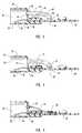
- FIG. 1is a perspective view of a PC card in accordance with a preferred embodiment of the invention.
- FIG. 2is a top view of the jack system mounted on the circuit board of the PC card shown in FIG. 1;
- FIG. 3is a cross sectional side view of the jack system shown in FIG. 2 taken along section line 3 — 3 ;
- FIG. 4is a cross sectional side view of another preferred embodiment of the jack system shown in FIG. 3;
- FIG. 5is a cross sectional side view of still another preferred embodiment of the jack system shown in FIG. 3;
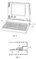
- FIG. 6is a perspective view of a computer including a preferred embodiment of the jack system formed thereon;
- FIG. 7is a cross sectional side view of the jack system shown in FIG. 6 .
- the present inventionrelates to electrical jacks that can be selectively illuminated and/or configured to illuminate an electrical plug coupled therewith so as to identify one or more predetermined operating conditions of the electrical jack and/or electrical apparatus coupled with the jack.
- FIG. 1Depicted in FIG. 1 is a preferred embodiment of a PC card 10 having an electrical jack system 12 incorporating features of the present invention.
- PC card 10can be configured in a variety of different form factors and can house electrical circuitry so as to perform a variety of one or more different functions.
- PC cardhas a housing 16 that extends from a first end 22 to an opposing second end 24 .
- housing 16bounds a compartment 18 in which a circuit board 20 is disposed.
- Located at first end 26 of housing 16is a conventional 68-pin connector for coupling PC card 10 to a conventional electrical apparatus, such as a personal computer.
- the PC card 10conforms to the Personal Computer Memory Card International Association (PCMCIA) standards or guidelines for a Type III card. Accordingly, the PC card desirably a length of 85.6 mm (3.4 inches), a width of 54.0 mm (2.1 inches), and a height of 10.5 mm (0.4 inches), but it will be appreciated that the card may have other desired sizes and configurations that are suitable for its intended purpose, and the card does not have to conform to any specific standards or guidelines.
- PCMCIAPersonal Computer Memory Card International Association
- the jack system 12includes a modular jack 27 which in turn comprises a jack housing 28 .
- jack housing 28has a front face 48 , a back wall 50 , opposing side walls 52 , 54 , a top wall 56 , and an opposing bottom wall 58 .
- Formed within front face 48 of jack housing 28is a first socket 30 and an adjacent second sockct 32 .
- jack housing 28can be incorporated into or formed integral with housing 16 and can contain one or more sockets.
- a preferred embodiment of a modular jack 27is described in assignee's copending U.S. patent application Ser.
- the modular jack 27has a height of about 10.5 mm measured from the top wall 56 to the bottom wall 58 , and the sockets 30 , 32 have a height of about 10.1 mm.
- the socks 30 , 32 located in the modular jack 27include a main body portion having a generally rectangular cnfiguration with an upper surface, a right side, a left side a front surface and a rear surface.
- the upper surface of the modular jack 27is preferrably generally aligned and substantially planar with the top surface of the housing of the communications card 10 .
- the top surface of the housingmay be configured to cover the upper surface of the modular jack 27 .
- the bottom surface of the communications card 10preferably encloses the lower surface of the modular jack 27 and is generally aligned with a lip located proximate the front surface of the jack.
- the lower surface of the modular jack 27may be generally aligned with the bottom surface of the communications card 10 .
- the height of the modular jack 27is the generally equal to or less than the height of the communications card 10 .
- the sockets 30 , 32are located entirely in the front surface of the modular jack 27 , and the upper surface of the modular jack is solid, planar surface that does not include any opening or cutouts.
- the modular jack 27includes a rearwardly extending connector 90 with a first end 92 attached to the modular jack and an opposing second end 94 .
- the rearwardly extending connector 90desirably has a length of about 8.7 mm and it is used to electrically connect the modular jack 27 to the circuit board 20 .
- the modular jack 27can have a variety of different sizes and configurations depending, for example, upon the type of connectors, intended use of the communications card, size and shape of the communications card, and specific applications of the communications card.
- a preferred embodiment of connecting the modular jack 27 to a circuit boardis disclosed in assignee's copending U.S. patent application Ser. No. 09/528,501, filed Mar. 20, 2000, entitled Card Edge Connector for a Modular Jack, which is hereby incorporated by reference in its entirety.
- One or more contacts 28are located within the sockets 30 , 32 of the modular jack 27 .
- four or six contactsare used in conjunction with an RJ-11 connector and eight contacts are used in conjunction with an RJ-45 connector, but any suitable number of contacts may be utilized.
- the contacts 38 shown in connection with these preferred embodimentscan be used in conjunction with RJ-11 and/or RJ-45 connectors, but one skilled in the art will recognize that the contacts may be manufactured in any of a wide variety of designs and configurations in order to be used with specific applications or connectors.
- the contacts 38comprise flexible pins that are in electrical communication with circuit board 20 .
- Preferred embodiments of the contact pinsare provided in assignee's copending U.S. patent application Ser. No. 09/528,500, filed Mar. 20, 2000, entitled Contact Pin Design for a Modular Jack, which is hereby incorporated by reference it its entirety.
- Socket 30is configured to receive an electrical plug 34 .
- electrical plug 34comprises an RJ-type plug, such as an RJ-9, 11, 25, or 45.
- Plug 34has a body 36 in electrical communication with a cable 40 .
- Body 36is typically molded from a plastic material which in one embodiment is at least partially translucent.
- Plug 34is configured to couple in electrical communication with contacts 38 when plug 34 is received within socket 30 .
- the present inventionalso includes means for illuminating socket 30 of housing 28 .
- a light emitter 42is mounted on circuit board 20 a distance from socket 30 .
- light emitter 42comprises any LED.
- light emitter 42can comprise a filament bulb, a laser, or any other sources capable of emitting light.
- a conduit 44extends between light emitter 42 and socket 30 .
- Conduit 44is configured to channel light from light emitter 42 to socket 30 .
- conduit 44comprises an elongated light pipe 46 having a first end 60 , an opposing second end 62 , and a curve 68 formed therebetween.
- light pipe 46is formed from a translucent plastic material such as polyethylene, polypropylene, or polystyrene, but one skilled in the art will appreciate that other suitable types of plastics, including elastomers, polymers, polyolefins and the like, or other suitable materials may be used.
- light pipe 46can be formed from glass, plastic or other at least partially translucent materials.
- the first end 60 of the light pipe 46is disposed within an opening 64 formed in a back wall 50 of jack housing 28 . As such, the light pipe 46 is exposed to the socket 30 .
- the present inventionalso envisioned that first end 60 can be disposed within an opening formed through side walls 52 , 54 , top wall 56 , and/or bottom wall 58 .
- first end 60 of light pipe 46need not be directly disposed within socket 30 but only aligned with opening 64 .
- the second end 62 of light pipe 46has an end face 66 having a substantially concave configuration. End face 66 is disposed over and adjacent to light emitter 42 so as to maximize the amount of light captured from light emitter 42 . In alternative embodiments, end face 66 can also be conical, flat, or any other desired configuration.
- Light emitter 42can be located at any desired position relative to jack housing 28 .
- light pipe 46can also have a variety of different configurations, i.e., straight and/or having one or more curves, to facilitate transfer of light from emitter 42 to socket 30 .
- light pipe 46is configured such that the central longitudinal axis extending through second end 62 of light pipe 46 is aligned with light emitter 42 . This configuration helps light pipe 46 to maximize the capture and transfer of light. Curves along the length of light pipe 46 are typically smooth and gradual so as to help prevent refraction of light out of light pipe 46 prior to exit through first end 60 .
- FIG. 4Depicted in FIG. 4 is an alternative embodiment of light pipe 46 depicted in FIG. 3 . Like elements in FIGS. 3 and 4 are identified by like reference characters. Depicted in FIG. 4 is a light pipe 70 having an enlarged first end 72 that integrally or connectably forms back wall 50 of housing 28 . In this regard, light pipe 70 is potentially capable of emitting light over a larger area within socket 30 . The present invention also envisions that first end 72 of light pipe 70 can form a portion of front face 48 , side walls 52 , 54 , top wall 56 , and/or bottom wall 58 .
- jack housing 28 or at least a portion of front face 48is formed from a translucent material and is coupled with light pipe 70 , the translucent portion of front face 48 is illuminated and exposed even when an opaque plug is received within socket 30 .
- Light pipe 70also has a second end 74 having a substantially flat end face 76 .
- alternative conduits 44include fiber optic materials, tubular piping members, and any other members or materials that will facilitate channeling and transfer of light.
- FIG. 5Depicted in FIG. 5 is an alternative embodiment of the means for illuminating socket 30 of housing 28 .
- light emitter 42is mounted directly on back wall 50 such that light emitted therefrom is directed into socket 30 .
- Light emitter 42is electrically coupled with circuit board through a flexible cable 78 and a connector 80 , such as a ZIF connector.
- a connector 80such as a ZIF connector.
- light emitter 42can comprise an LED or other apparatus configured to emit light.
- the present inventionalso envisions that light emitter 42 can be mounted on side walls 52 , 54 , top wall 56 , and/or bottom wall 58 .
- the illumination of socket 30may be sufficiently intense so as to be noticeable during normal use in a lighted room.
- the intensitymay be so minimal that absent viewing directly into socket 30 , illumination would not be noticed in a lighted room.
- the present inventionalso envisions that in one embodiment, insertion of translucent plug 34 into socket 30 results in the illumination of plug 34 .
- FIGS. 1-5show modular jack 27 being incorporated into jack system 12
- the present inventionenvisions that a variety of alternative electrical jacks can be incorporated into jack system 12 for selective illumination.
- such jacksinclude PC card I/O connectors, pin connectors, USB connectors, fiber optic connectors, and conventional electrical outlets.
- corresponding plugswould be used with such jacks.
- jack system 12is discussed above as being used in a PC card, the inventive jack system can be used in any electrical apparatus.
- such electrical apparatuscan include personal information managers, personal computers, network computers, electrical diagnostic apparatus, and any other type of electrical equipment wherein electrical jacks are used.
- FIG. 6depicted in FIG. 6 is a personal computer 80 having an inventive jack system 82 incorporated therein.
- Personal computer 80includes a housing 88 in which a socket 84 is integrally formed.
- Socket 84is configured to receive an RJ-type electrical plug 34 in electrical communication.
- a light emitter 42is disposed on a circuit board 86 or other structure positioned within housing 88 .
- Conduit 44extends between socket 84 and light emitter 42 so as to selectively illuminate socket 84 and/or an electrical plug received therein.
- the present inventionenvisions that the illumination of socket 30 , 84 and/or the electrical plug received therein can be used to signify a variety of different things.
- illumination of a socket and/or plugcan be used to designate whether the jack and/or plug are properly connected, whether they are in condition for operation, or whether they are currently in operation.
- the socket and/or plugcan also be illuminated with different colors to designate different stages of operation.
- the socket and/or plugcan also be selectively illuminated to designate what component or software of the electrical apparatus is in operation.
Landscapes
- Engineering & Computer Science (AREA)
- Computer Hardware Design (AREA)
- Theoretical Computer Science (AREA)
- Physics & Mathematics (AREA)
- General Engineering & Computer Science (AREA)
- Human Computer Interaction (AREA)
- General Physics & Mathematics (AREA)
- Microelectronics & Electronic Packaging (AREA)
- Mathematical Physics (AREA)
- Details Of Connecting Devices For Male And Female Coupling (AREA)
Abstract
Description
Claims (25)
Priority Applications (1)
| Application Number | Priority Date | Filing Date | Title |
|---|---|---|---|
| US09/528,330US6483712B1 (en) | 2000-03-20 | 2000-03-20 | Illuminating electrical jack system |
Applications Claiming Priority (1)
| Application Number | Priority Date | Filing Date | Title |
|---|---|---|---|
| US09/528,330US6483712B1 (en) | 2000-03-20 | 2000-03-20 | Illuminating electrical jack system |
Publications (1)
| Publication Number | Publication Date |
|---|---|
| US6483712B1true US6483712B1 (en) | 2002-11-19 |
Family
ID=24105231
Family Applications (1)
| Application Number | Title | Priority Date | Filing Date |
|---|---|---|---|
| US09/528,330Expired - Fee RelatedUS6483712B1 (en) | 2000-03-20 | 2000-03-20 | Illuminating electrical jack system |
Country Status (1)
| Country | Link |
|---|---|
| US (1) | US6483712B1 (en) |
Cited By (34)
| Publication number | Priority date | Publication date | Assignee | Title |
|---|---|---|---|---|
| US20040005820A1 (en)* | 2001-03-16 | 2004-01-08 | Gutierrez Aurelio J. | Advanced microelectronic connector assembly and method of manufacturing |
| US20040040871A1 (en)* | 2002-08-27 | 2004-03-04 | Murata Manufacturing Co., Ltd. | Appearance protective case and appearance protective case assembly |
| US20040097912A1 (en)* | 2002-11-18 | 2004-05-20 | Gonnering Wayne J. | Electrosurgical generator and method with removable front panel having replaceable electrical connection sockets and illuminated receptacles |
| US20040224768A1 (en)* | 2002-09-24 | 2004-11-11 | Saied Hussaini | Video game controller with integrated status indicators |
| US20050032415A1 (en)* | 2003-08-05 | 2005-02-10 | Rikio Sakamoto | Connector component and connector assembly |
| US20050066103A1 (en)* | 2003-09-08 | 2005-03-24 | Nec Infrontia Corporation | PC card device with indicator having good visibility |
| US20050063647A1 (en)* | 2003-09-19 | 2005-03-24 | Thornton Martin Q. | Modular receptacle assembly and interface with integral optical indication |
| US6890188B1 (en)* | 2004-02-27 | 2005-05-10 | Imation Corp. | Memory card compatible with device connector and host connector standards |
| US20050101180A1 (en)* | 2003-11-06 | 2005-05-12 | Belkin Corporation | Electrical connector |
| US20050106930A1 (en)* | 2003-11-13 | 2005-05-19 | Benq Corporation | Plug detecting device |
| US20050245103A1 (en)* | 2004-04-30 | 2005-11-03 | Ellison Thomas L | Transceiver module having a flexible circuit |
| US20050254772A1 (en)* | 2004-05-14 | 2005-11-17 | Long Jerry A | Light pipe assembly for use with small form factor connector |
| US20050266723A1 (en)* | 2004-06-01 | 2005-12-01 | Enterasys Networks, Inc. | Visual optical indicators for plug assemblies, connectors and cables |
| US7019658B1 (en)* | 2003-03-04 | 2006-03-28 | Mobi Technologies, Inc. | Cable traffic indicator |
| US7207846B2 (en) | 2003-11-24 | 2007-04-24 | Panduit Corp. | Patch panel with a motherboard for connecting communication jacks |
| US7376734B2 (en) | 2002-02-14 | 2008-05-20 | Panduit Corp. | VOIP telephone location system |
| US20080214140A1 (en)* | 2005-09-28 | 2008-09-04 | Panduit Corp. | Powered patch panel |
| US7439449B1 (en) | 2002-02-14 | 2008-10-21 | Finisar Corporation | Flexible circuit for establishing electrical connectivity with optical subassembly |
| US7446261B2 (en) | 2001-09-06 | 2008-11-04 | Finisar Corporation | Flexible circuit boards with tooling cutouts for optoelectronic modules |
| US7455527B2 (en) | 2004-05-03 | 2008-11-25 | Panduit Corp. | Powered patch panel |
| US7519000B2 (en) | 2002-01-30 | 2009-04-14 | Panduit Corp. | Systems and methods for managing a network |
| US7526207B2 (en) | 2002-10-18 | 2009-04-28 | Finisar Corporation | Flexible circuit design for improved laser bias connections to optical subassemblies |
| CN101572369A (en)* | 2008-04-30 | 2009-11-04 | 泰科电子公司 | Connector assembly having a light pipe assembly |
| US20090280677A1 (en)* | 2008-05-07 | 2009-11-12 | Tyco Electronics Corporation | Illuminated circular plastic connector |
| US7629537B2 (en) | 2004-07-09 | 2009-12-08 | Finisar Corporation | Single layer flex circuit |
| US7708586B1 (en) | 2009-01-27 | 2010-05-04 | Tyco Electronics Corporation | Illuminated panel-mount connector receptacle |
| US20100144191A1 (en)* | 2004-06-29 | 2010-06-10 | Russell Lee Machado | Universal connector assembly and method of manufacturing |
| US20110230065A1 (en)* | 2008-12-04 | 2011-09-22 | Tyco Electronics Amp Gmbh | Connector housing with light guide element |
| WO2012121833A1 (en)* | 2011-03-09 | 2012-09-13 | Universal Electronics Inc. | System and method for provision of infrared signalling in smart phone devices |
| US8325770B2 (en) | 2003-08-06 | 2012-12-04 | Panduit Corp. | Network managed device installation and provisioning technique |
| US20130078849A1 (en)* | 2011-09-23 | 2013-03-28 | Avaya Inc. | Connector illumination status |
| US9460684B2 (en) | 2008-01-31 | 2016-10-04 | Hewlett-Packard Development Company, L.P. | System and method for illuminating connector ports |
| US20170005730A1 (en)* | 2014-01-27 | 2017-01-05 | Napatech A/S | Activity diodes and reflective housings |
| US9859666B1 (en) | 2017-01-12 | 2018-01-02 | International Business Machines Corporation | Illuminated latch release for cable |
Citations (86)
| Publication number | Priority date | Publication date | Assignee | Title |
|---|---|---|---|---|
| US2916720A (en) | 1957-08-14 | 1959-12-08 | Robert B Steans | Electrical connector |
| US3500293A (en) | 1968-06-12 | 1970-03-10 | Bell Telephone Labor Inc | Connector including a visual indicator |
| US4136357A (en) | 1977-10-03 | 1979-01-23 | National Semiconductor Corporation | Integrated circuit package with optical input coupler |
| US4186988A (en) | 1978-09-20 | 1980-02-05 | Amp Incorporated | Electrical connector receptacles |
| US4241974A (en) | 1979-05-02 | 1980-12-30 | Western Electric Company, Inc. | Multi-outlet adapter for modular telephone cords |
| US4303296A (en) | 1978-05-03 | 1981-12-01 | Bunker Ramo Corporation | Modular interface connector |
| US4352492A (en) | 1976-08-23 | 1982-10-05 | Fairchild Camera & Instrument Corp. | Data storage apparatus |
| US4386818A (en) | 1981-04-27 | 1983-06-07 | Amp Incorporated | Polarity indicating connector for battery jumper cables |
| US4407559A (en) | 1981-04-09 | 1983-10-04 | Communications Systems, Inc. | Connector device with flush mounting receptacle, cover plate and terminal board |
| US4428636A (en) | 1981-11-05 | 1984-01-31 | Amp Incorporated | Multi-contact connectors for closely spaced conductors |
| US4564728A (en) | 1984-04-13 | 1986-01-14 | Comus International, Inc. | Apparatus for testing a telephone line |
| US4566769A (en) | 1982-12-29 | 1986-01-28 | Olympus Optical Co., Ltd. | Power supply unit for electronic flash |
| US4620070A (en) | 1985-02-04 | 1986-10-28 | Illinois Tool Works Inc. | Telephone line tester |
| JPS61256850A (en) | 1985-05-08 | 1986-11-14 | Fujitsu Ltd | Preventing plug for radio wave of telephone set |
| USD291071S (en) | 1985-03-28 | 1987-07-28 | Breil Randy J | Telephone line polarity tester |
| US4710136A (en) | 1982-02-26 | 1987-12-01 | Nippon Electric Co., Ltd. | Mounting structure for electronic apparatus or the like |
| US4778410A (en) | 1986-09-22 | 1988-10-18 | Hosiden Electronics Co., Ltd. | Jack |
| US4789224A (en) | 1987-05-04 | 1988-12-06 | General Motors Corporation | Instrument panel having light pipe having legs |
| US4800466A (en) | 1985-10-08 | 1989-01-24 | Preh, Elektrofeinmechanische Werke, Jakob Preh, Nachf. Gmbh & Co. | Illumination device for a front panel |
| GB2214007A (en) | 1987-12-18 | 1989-08-23 | Bulgin & Co Plc A F | Electrical connector with neon indicator |
| US4887876A (en) | 1987-11-07 | 1989-12-19 | C. A. Weidmueller Gmbh & Co. | Electrical connector including light-conducting means |
| US4915648A (en) | 1988-03-04 | 1990-04-10 | Fuji Jukogyo Kabushiki Kaisha | Connector with a lock mechanism |
| GB2229029A (en) | 1989-02-21 | 1990-09-12 | Telemecanique | Electric state signaling appliance |
| US4978317A (en) | 1989-03-27 | 1990-12-18 | Alan Pocrass | Connector with visual indicator |
| US5035641A (en) | 1988-02-15 | 1991-07-30 | Itt Industries Limited | Terminating insulated conductors |
| US5051099A (en) | 1990-01-10 | 1991-09-24 | Amp Incorporated | High speed card edge connector |
| US5062807A (en) | 1990-10-22 | 1991-11-05 | Woodhead Industries, Inc. | Lighted electrical connector permitting multi directional viewing |
| GB2247118A (en) | 1990-08-13 | 1992-02-19 | Brother Ind Ltd | Multi-function status and fault indicator for a recording device |
| GB2247363A (en) | 1990-07-26 | 1992-02-26 | Nce Electrical | Electrical adaptor assembly |
| US5139439A (en) | 1991-07-16 | 1992-08-18 | Veridata Electronics Inc. | Portable computer with detachable cartridge type interface device |
| US5184282A (en) | 1989-02-27 | 1993-02-02 | Mips Co., Ltd. | IC card adapter |
| US5183404A (en) | 1992-04-08 | 1993-02-02 | Megahertz Corporation | Systems for connection of physical/electrical media connectors to computer communications cards |
| US5319527A (en) | 1992-11-20 | 1994-06-07 | Delco Electronics Corporation | Illuminated instrumentation display |
| US5345367A (en) | 1992-09-22 | 1994-09-06 | Intel Corporation | Thin form factor computer card |
| US5359165A (en) | 1993-07-16 | 1994-10-25 | Eaton Corporation | Illuminated rotary switch assembly |
| US5391094A (en) | 1992-11-20 | 1995-02-21 | Murata Mfg. Co., Ltd. | Card-type line interface device |
| US5411405A (en) | 1993-11-12 | 1995-05-02 | Angia Communications, Inc. | Miniature electrical communications connectors |
| US5457600A (en) | 1994-07-20 | 1995-10-10 | American Power Conversion Corporation | Power surge protector |
| US5474463A (en) | 1993-07-26 | 1995-12-12 | Greystone Peripherals, Inc. | Bay for receiving removable peripheral device |
| US5481616A (en) | 1993-11-08 | 1996-01-02 | Sparkomatic Corporation | Plug-in sound accessory for portable computers |
| US5487123A (en) | 1994-10-31 | 1996-01-23 | Delco Electronics Corporation | Connectors for optical fibers including resilient/expandable members |
| US5499923A (en) | 1994-11-09 | 1996-03-19 | At&T Corp. | Communication card with extendible, rotatable coupling |
| US5505633A (en) | 1994-05-13 | 1996-04-09 | Intel Corporation | Integral external connector interface for thin form factor computer cards |
| US5509811A (en) | 1994-01-12 | 1996-04-23 | Dell Usa, L.P. | Computer enclosure with embedded PCMCIA modem card |
| US5513373A (en) | 1994-03-21 | 1996-04-30 | Motorola, Inc. | Apparatus using three light emitting diodes (LEDs) and a transistor for indicating whether there is an overtermination undertermination, or power termination of peripheral devices |
| US5538442A (en) | 1993-10-04 | 1996-07-23 | Murata Mfg. Co., Ltd. | Communication card |
| US5547401A (en) | 1992-04-08 | 1996-08-20 | Megahertz Corporation | Media connector interface for use with a thin-architecture communications card |
| US5561727A (en) | 1994-02-15 | 1996-10-01 | Sumitomo Electric Industries, Ltd. | Card-shaped optical data link device |
| US5562504A (en) | 1995-01-04 | 1996-10-08 | Simple Technology Incorporated | Communications card with integral transmission media line adaptor |
| US5597227A (en) | 1995-08-11 | 1997-01-28 | Emhart Inc. | Illuminated door lock |
| US5608607A (en) | 1995-04-24 | 1997-03-04 | Compaq Computer Corporation | PCMCIA card and associated support and circuitry augmenting apparatus and methods |
| US5613873A (en) | 1993-12-16 | 1997-03-25 | Dell Usa, L.P. | Modular jack with integral light-emitting diode |
| US5634802A (en) | 1994-08-18 | 1997-06-03 | International Business Machines Corporation | Retractable expandable jack |
| US5646816A (en) | 1994-03-18 | 1997-07-08 | Lucent Technologies Inc. | Identification icon indicia for plug-in units of a power distribution system |
| US5645577A (en) | 1994-06-29 | 1997-07-08 | Pacesetter Ab | Connection indicator for medical device |
| US5654873A (en) | 1996-01-29 | 1997-08-05 | Silicon Graphics, Inc. | Single connector attachment drive sled assembly having light pipe coupled to a rail |
| US5660568A (en) | 1995-01-04 | 1997-08-26 | Simple Technology, Inc. | Communications card with integral transmission media line adaptor |
| US5667395A (en) | 1994-08-29 | 1997-09-16 | Murata Mfg. Co., Ltd. | Communication card and structure of jack for use in the same |
| US5668654A (en) | 1995-05-30 | 1997-09-16 | The Whitaker Corporation | Package for an infrared communications adapter |
| US5679013A (en) | 1994-11-14 | 1997-10-21 | International Business Machines Corporation | Electrical connector and an electronic apparatus using the electrical connector |
| US5692914A (en) | 1995-01-24 | 1997-12-02 | Mitsubishi Denki Kabushiki Kaisha | PC card including a jack for a connector |
| US5697815A (en) | 1995-06-07 | 1997-12-16 | Drewnicki; Richard | Electrical connectors |
| US5704802A (en) | 1996-06-14 | 1998-01-06 | Maxconn Incorporated | Modular jack assembly |
| GB2315926A (en) | 1996-07-29 | 1998-02-11 | Whitaker Corp | An electrical connector having a visual indicator |
| GB2316816A (en) | 1996-08-30 | 1998-03-04 | Whitaker Corp | An electrical connector having a visual indicator |
| US5741152A (en) | 1995-04-25 | 1998-04-21 | Amphenol Corporation | Electrical connector with indicator lights |
| US5759067A (en) | 1996-12-11 | 1998-06-02 | Scheer; Peter L. | Shielded connector |
| US5767623A (en) | 1995-09-11 | 1998-06-16 | Planar Systems, Inc. | Interconnection between an active matrix electroluminescent display and an electrical cable |
| US5773332A (en) | 1993-11-12 | 1998-06-30 | Xircom, Inc. | Adaptable communications connectors |
| US5790041A (en) | 1995-02-14 | 1998-08-04 | Advanced Micro Devices, Inc. | Apparatus and method to display network connection status on a jack panel |
| US5797771A (en) | 1996-08-16 | 1998-08-25 | U.S. Robotics Mobile Communication Corp. | Cable connector |
| US5816832A (en) | 1992-04-08 | 1998-10-06 | 3Com Corporation | Media connector interface for use with a PCMCIA-architecture communications card |
| US5876239A (en) | 1996-08-30 | 1999-03-02 | The Whitaker Corporation | Electrical connector having a light indicator |
| US5885100A (en) | 1997-05-12 | 1999-03-23 | Molex Incorporated | Electrical connector with light transmission means |
| US5915060A (en) | 1997-09-17 | 1999-06-22 | Aiwa Co., Ltd. | Light pipe array |
| US5915993A (en) | 1997-02-27 | 1999-06-29 | Berg Technology, Inc. | Assembly containing a modular jack and a light emitting diode |
| US5938324A (en) | 1996-10-07 | 1999-08-17 | Cisco Technology, Inc. | Light pipe |
| US5967817A (en) | 1995-11-21 | 1999-10-19 | Heartstream, Inc. | Medical connector apparatus |
| US5971558A (en) | 1996-06-06 | 1999-10-26 | Kuhlman Corporation | Method and apparatus for mounting an instrument |
| US6062908A (en) | 1997-01-27 | 2000-05-16 | Pulse Engineering, Inc. | High density connector modules having integral filtering components within repairable, replaceable submodules |
| US6075215A (en) | 1999-03-29 | 2000-06-13 | Siemens Energy & Automation, Inc. | Light pipe indicator assembly for a stored energy circuit breaker operator assembly |
| US6095851A (en)* | 1997-11-17 | 2000-08-01 | Xircom, Inc. | Status indicator for electronic device |
| US6113422A (en)* | 1994-11-30 | 2000-09-05 | Berg Technology, Inc. | Connector with circuit devices and indicators |
| US6116962A (en) | 1997-11-17 | 2000-09-12 | Xircom Inc | Type III PCMCIA card with integrated receptacles for receiving standard communications plugs |
| US6217391B1 (en)* | 1998-03-26 | 2001-04-17 | Stewart Connector Systems, Inc. | Low profile modular electrical jack and communication card including the same |
| US6224417B1 (en)* | 1997-02-27 | 2001-05-01 | Berg Technology, Inc. | Assembly containing a modular jack and a light emitting diode |
- 2000
- 2000-03-20USUS09/528,330patent/US6483712B1/ennot_activeExpired - Fee Related
Patent Citations (90)
| Publication number | Priority date | Publication date | Assignee | Title |
|---|---|---|---|---|
| US2916720A (en) | 1957-08-14 | 1959-12-08 | Robert B Steans | Electrical connector |
| US3500293A (en) | 1968-06-12 | 1970-03-10 | Bell Telephone Labor Inc | Connector including a visual indicator |
| US4352492A (en) | 1976-08-23 | 1982-10-05 | Fairchild Camera & Instrument Corp. | Data storage apparatus |
| US4136357A (en) | 1977-10-03 | 1979-01-23 | National Semiconductor Corporation | Integrated circuit package with optical input coupler |
| US4303296A (en) | 1978-05-03 | 1981-12-01 | Bunker Ramo Corporation | Modular interface connector |
| US4186988A (en) | 1978-09-20 | 1980-02-05 | Amp Incorporated | Electrical connector receptacles |
| US4241974A (en) | 1979-05-02 | 1980-12-30 | Western Electric Company, Inc. | Multi-outlet adapter for modular telephone cords |
| US4407559A (en) | 1981-04-09 | 1983-10-04 | Communications Systems, Inc. | Connector device with flush mounting receptacle, cover plate and terminal board |
| US4386818A (en) | 1981-04-27 | 1983-06-07 | Amp Incorporated | Polarity indicating connector for battery jumper cables |
| US4428636A (en) | 1981-11-05 | 1984-01-31 | Amp Incorporated | Multi-contact connectors for closely spaced conductors |
| US4710136A (en) | 1982-02-26 | 1987-12-01 | Nippon Electric Co., Ltd. | Mounting structure for electronic apparatus or the like |
| US4566769A (en) | 1982-12-29 | 1986-01-28 | Olympus Optical Co., Ltd. | Power supply unit for electronic flash |
| US4564728A (en) | 1984-04-13 | 1986-01-14 | Comus International, Inc. | Apparatus for testing a telephone line |
| US4620070A (en) | 1985-02-04 | 1986-10-28 | Illinois Tool Works Inc. | Telephone line tester |
| USD291071S (en) | 1985-03-28 | 1987-07-28 | Breil Randy J | Telephone line polarity tester |
| JPS61256850A (en) | 1985-05-08 | 1986-11-14 | Fujitsu Ltd | Preventing plug for radio wave of telephone set |
| US4800466A (en) | 1985-10-08 | 1989-01-24 | Preh, Elektrofeinmechanische Werke, Jakob Preh, Nachf. Gmbh & Co. | Illumination device for a front panel |
| US4778410A (en) | 1986-09-22 | 1988-10-18 | Hosiden Electronics Co., Ltd. | Jack |
| US4789224A (en) | 1987-05-04 | 1988-12-06 | General Motors Corporation | Instrument panel having light pipe having legs |
| US4887876A (en) | 1987-11-07 | 1989-12-19 | C. A. Weidmueller Gmbh & Co. | Electrical connector including light-conducting means |
| GB2214007A (en) | 1987-12-18 | 1989-08-23 | Bulgin & Co Plc A F | Electrical connector with neon indicator |
| US5035641A (en) | 1988-02-15 | 1991-07-30 | Itt Industries Limited | Terminating insulated conductors |
| US4915648A (en) | 1988-03-04 | 1990-04-10 | Fuji Jukogyo Kabushiki Kaisha | Connector with a lock mechanism |
| GB2229029A (en) | 1989-02-21 | 1990-09-12 | Telemecanique | Electric state signaling appliance |
| US5184282A (en) | 1989-02-27 | 1993-02-02 | Mips Co., Ltd. | IC card adapter |
| US4978317A (en) | 1989-03-27 | 1990-12-18 | Alan Pocrass | Connector with visual indicator |
| US5051099A (en) | 1990-01-10 | 1991-09-24 | Amp Incorporated | High speed card edge connector |
| GB2247363A (en) | 1990-07-26 | 1992-02-26 | Nce Electrical | Electrical adaptor assembly |
| GB2247118A (en) | 1990-08-13 | 1992-02-19 | Brother Ind Ltd | Multi-function status and fault indicator for a recording device |
| US5062807A (en) | 1990-10-22 | 1991-11-05 | Woodhead Industries, Inc. | Lighted electrical connector permitting multi directional viewing |
| US5139439A (en) | 1991-07-16 | 1992-08-18 | Veridata Electronics Inc. | Portable computer with detachable cartridge type interface device |
| US5727972A (en) | 1992-04-08 | 1998-03-17 | Aldous; Stephen C. | Media connector interface for use with a thin-architecture communications card |
| US5183404A (en) | 1992-04-08 | 1993-02-02 | Megahertz Corporation | Systems for connection of physical/electrical media connectors to computer communications cards |
| US5336099A (en) | 1992-04-08 | 1994-08-09 | Megahertz Corporation | Media connector interface for use with a PCMCIA-architecture communications card |
| US5338210A (en) | 1992-04-08 | 1994-08-16 | Megahertz Corporation | Media connector interface for use with a PCMCIA-architecture communications card |
| US5547401A (en) | 1992-04-08 | 1996-08-20 | Megahertz Corporation | Media connector interface for use with a thin-architecture communications card |
| US5816832A (en) | 1992-04-08 | 1998-10-06 | 3Com Corporation | Media connector interface for use with a PCMCIA-architecture communications card |
| US5345367A (en) | 1992-09-22 | 1994-09-06 | Intel Corporation | Thin form factor computer card |
| US5319527A (en) | 1992-11-20 | 1994-06-07 | Delco Electronics Corporation | Illuminated instrumentation display |
| US5391094A (en) | 1992-11-20 | 1995-02-21 | Murata Mfg. Co., Ltd. | Card-type line interface device |
| US5359165A (en) | 1993-07-16 | 1994-10-25 | Eaton Corporation | Illuminated rotary switch assembly |
| US5474463A (en) | 1993-07-26 | 1995-12-12 | Greystone Peripherals, Inc. | Bay for receiving removable peripheral device |
| US5538442A (en) | 1993-10-04 | 1996-07-23 | Murata Mfg. Co., Ltd. | Communication card |
| US5481616A (en) | 1993-11-08 | 1996-01-02 | Sparkomatic Corporation | Plug-in sound accessory for portable computers |
| WO1995013633A1 (en) | 1993-11-12 | 1995-05-18 | Angia Communications, Inc. | Adaptable communications connectors |
| US5411405A (en) | 1993-11-12 | 1995-05-02 | Angia Communications, Inc. | Miniature electrical communications connectors |
| US5773332A (en) | 1993-11-12 | 1998-06-30 | Xircom, Inc. | Adaptable communications connectors |
| US5613873A (en) | 1993-12-16 | 1997-03-25 | Dell Usa, L.P. | Modular jack with integral light-emitting diode |
| US5509811A (en) | 1994-01-12 | 1996-04-23 | Dell Usa, L.P. | Computer enclosure with embedded PCMCIA modem card |
| US5561727A (en) | 1994-02-15 | 1996-10-01 | Sumitomo Electric Industries, Ltd. | Card-shaped optical data link device |
| US5646816A (en) | 1994-03-18 | 1997-07-08 | Lucent Technologies Inc. | Identification icon indicia for plug-in units of a power distribution system |
| US5513373A (en) | 1994-03-21 | 1996-04-30 | Motorola, Inc. | Apparatus using three light emitting diodes (LEDs) and a transistor for indicating whether there is an overtermination undertermination, or power termination of peripheral devices |
| US5505633A (en) | 1994-05-13 | 1996-04-09 | Intel Corporation | Integral external connector interface for thin form factor computer cards |
| US5645577A (en) | 1994-06-29 | 1997-07-08 | Pacesetter Ab | Connection indicator for medical device |
| US5457600A (en) | 1994-07-20 | 1995-10-10 | American Power Conversion Corporation | Power surge protector |
| US5634802A (en) | 1994-08-18 | 1997-06-03 | International Business Machines Corporation | Retractable expandable jack |
| US5667395A (en) | 1994-08-29 | 1997-09-16 | Murata Mfg. Co., Ltd. | Communication card and structure of jack for use in the same |
| US5487123A (en) | 1994-10-31 | 1996-01-23 | Delco Electronics Corporation | Connectors for optical fibers including resilient/expandable members |
| US5499923A (en) | 1994-11-09 | 1996-03-19 | At&T Corp. | Communication card with extendible, rotatable coupling |
| US5679013A (en) | 1994-11-14 | 1997-10-21 | International Business Machines Corporation | Electrical connector and an electronic apparatus using the electrical connector |
| US6113422A (en)* | 1994-11-30 | 2000-09-05 | Berg Technology, Inc. | Connector with circuit devices and indicators |
| US5660568A (en) | 1995-01-04 | 1997-08-26 | Simple Technology, Inc. | Communications card with integral transmission media line adaptor |
| US5562504A (en) | 1995-01-04 | 1996-10-08 | Simple Technology Incorporated | Communications card with integral transmission media line adaptor |
| US5692914A (en) | 1995-01-24 | 1997-12-02 | Mitsubishi Denki Kabushiki Kaisha | PC card including a jack for a connector |
| US5790041A (en) | 1995-02-14 | 1998-08-04 | Advanced Micro Devices, Inc. | Apparatus and method to display network connection status on a jack panel |
| US5608607A (en) | 1995-04-24 | 1997-03-04 | Compaq Computer Corporation | PCMCIA card and associated support and circuitry augmenting apparatus and methods |
| US5741152A (en) | 1995-04-25 | 1998-04-21 | Amphenol Corporation | Electrical connector with indicator lights |
| US5668654A (en) | 1995-05-30 | 1997-09-16 | The Whitaker Corporation | Package for an infrared communications adapter |
| US5697815A (en) | 1995-06-07 | 1997-12-16 | Drewnicki; Richard | Electrical connectors |
| US5597227A (en) | 1995-08-11 | 1997-01-28 | Emhart Inc. | Illuminated door lock |
| US5767623A (en) | 1995-09-11 | 1998-06-16 | Planar Systems, Inc. | Interconnection between an active matrix electroluminescent display and an electrical cable |
| US5967817A (en) | 1995-11-21 | 1999-10-19 | Heartstream, Inc. | Medical connector apparatus |
| US5654873A (en) | 1996-01-29 | 1997-08-05 | Silicon Graphics, Inc. | Single connector attachment drive sled assembly having light pipe coupled to a rail |
| US5971558A (en) | 1996-06-06 | 1999-10-26 | Kuhlman Corporation | Method and apparatus for mounting an instrument |
| US5704802A (en) | 1996-06-14 | 1998-01-06 | Maxconn Incorporated | Modular jack assembly |
| GB2315926A (en) | 1996-07-29 | 1998-02-11 | Whitaker Corp | An electrical connector having a visual indicator |
| US5797771A (en) | 1996-08-16 | 1998-08-25 | U.S. Robotics Mobile Communication Corp. | Cable connector |
| GB2316816A (en) | 1996-08-30 | 1998-03-04 | Whitaker Corp | An electrical connector having a visual indicator |
| US5876239A (en) | 1996-08-30 | 1999-03-02 | The Whitaker Corporation | Electrical connector having a light indicator |
| US5938324A (en) | 1996-10-07 | 1999-08-17 | Cisco Technology, Inc. | Light pipe |
| US5759067A (en) | 1996-12-11 | 1998-06-02 | Scheer; Peter L. | Shielded connector |
| US6062908A (en) | 1997-01-27 | 2000-05-16 | Pulse Engineering, Inc. | High density connector modules having integral filtering components within repairable, replaceable submodules |
| US5915993A (en) | 1997-02-27 | 1999-06-29 | Berg Technology, Inc. | Assembly containing a modular jack and a light emitting diode |
| US6224417B1 (en)* | 1997-02-27 | 2001-05-01 | Berg Technology, Inc. | Assembly containing a modular jack and a light emitting diode |
| US5885100A (en) | 1997-05-12 | 1999-03-23 | Molex Incorporated | Electrical connector with light transmission means |
| US5915060A (en) | 1997-09-17 | 1999-06-22 | Aiwa Co., Ltd. | Light pipe array |
| US6095851A (en)* | 1997-11-17 | 2000-08-01 | Xircom, Inc. | Status indicator for electronic device |
| US6116962A (en) | 1997-11-17 | 2000-09-12 | Xircom Inc | Type III PCMCIA card with integrated receptacles for receiving standard communications plugs |
| US6217391B1 (en)* | 1998-03-26 | 2001-04-17 | Stewart Connector Systems, Inc. | Low profile modular electrical jack and communication card including the same |
| US6075215A (en) | 1999-03-29 | 2000-06-13 | Siemens Energy & Automation, Inc. | Light pipe indicator assembly for a stored energy circuit breaker operator assembly |
Non-Patent Citations (1)
| Title |
|---|
| P.E. Knight and D.R. Smith "Electrical Connector for Flat Flexible Cable," IBM Technical Disclosure Bulletin, vol. 25, No. 1, Jun. 1982. |
Cited By (56)
| Publication number | Priority date | Publication date | Assignee | Title |
|---|---|---|---|---|
| US6962511B2 (en) | 2001-03-16 | 2005-11-08 | Pulse Engineering, Inc. | Advanced microelectronic connector assembly and method of manufacturing |
| US20040005820A1 (en)* | 2001-03-16 | 2004-01-08 | Gutierrez Aurelio J. | Advanced microelectronic connector assembly and method of manufacturing |
| US7446261B2 (en) | 2001-09-06 | 2008-11-04 | Finisar Corporation | Flexible circuit boards with tooling cutouts for optoelectronic modules |
| US7519000B2 (en) | 2002-01-30 | 2009-04-14 | Panduit Corp. | Systems and methods for managing a network |
| US7439449B1 (en) | 2002-02-14 | 2008-10-21 | Finisar Corporation | Flexible circuit for establishing electrical connectivity with optical subassembly |
| US7376734B2 (en) | 2002-02-14 | 2008-05-20 | Panduit Corp. | VOIP telephone location system |
| US20040040871A1 (en)* | 2002-08-27 | 2004-03-04 | Murata Manufacturing Co., Ltd. | Appearance protective case and appearance protective case assembly |
| US7375972B2 (en)* | 2002-08-27 | 2008-05-20 | Murata Manufacturing Co., Ltd. | Appearance protective case and appearance protective case assembly |
| US20040224768A1 (en)* | 2002-09-24 | 2004-11-11 | Saied Hussaini | Video game controller with integrated status indicators |
| US7526207B2 (en) | 2002-10-18 | 2009-04-28 | Finisar Corporation | Flexible circuit design for improved laser bias connections to optical subassemblies |
| US20040097912A1 (en)* | 2002-11-18 | 2004-05-20 | Gonnering Wayne J. | Electrosurgical generator and method with removable front panel having replaceable electrical connection sockets and illuminated receptacles |
| US7019658B1 (en)* | 2003-03-04 | 2006-03-28 | Mobi Technologies, Inc. | Cable traffic indicator |
| US20060286856A1 (en)* | 2003-08-05 | 2006-12-21 | Nec Corporation | Connector component and connector assembly |
| US20050032415A1 (en)* | 2003-08-05 | 2005-02-10 | Rikio Sakamoto | Connector component and connector assembly |
| US8325770B2 (en) | 2003-08-06 | 2012-12-04 | Panduit Corp. | Network managed device installation and provisioning technique |
| US20050066103A1 (en)* | 2003-09-08 | 2005-03-24 | Nec Infrontia Corporation | PC card device with indicator having good visibility |
| US7194183B2 (en) | 2003-09-19 | 2007-03-20 | Enterasys Networks, Inc. | Modular receptacle assembly and interface with integral optical indication |
| US20050063647A1 (en)* | 2003-09-19 | 2005-03-24 | Thornton Martin Q. | Modular receptacle assembly and interface with integral optical indication |
| US20050101180A1 (en)* | 2003-11-06 | 2005-05-12 | Belkin Corporation | Electrical connector |
| US6921284B2 (en) | 2003-11-06 | 2005-07-26 | Belkin Corporation | Electrical connector |
| US20050106930A1 (en)* | 2003-11-13 | 2005-05-19 | Benq Corporation | Plug detecting device |
| US7121873B2 (en)* | 2003-11-13 | 2006-10-17 | Benq Corporation | Plug detecting device |
| US7207846B2 (en) | 2003-11-24 | 2007-04-24 | Panduit Corp. | Patch panel with a motherboard for connecting communication jacks |
| US6890188B1 (en)* | 2004-02-27 | 2005-05-10 | Imation Corp. | Memory card compatible with device connector and host connector standards |
| US7275937B2 (en)* | 2004-04-30 | 2007-10-02 | Finisar Corporation | Optoelectronic module with components mounted on a flexible circuit |
| US20050245103A1 (en)* | 2004-04-30 | 2005-11-03 | Ellison Thomas L | Transceiver module having a flexible circuit |
| US7455527B2 (en) | 2004-05-03 | 2008-11-25 | Panduit Corp. | Powered patch panel |
| US20050254772A1 (en)* | 2004-05-14 | 2005-11-17 | Long Jerry A | Light pipe assembly for use with small form factor connector |
| US20050266723A1 (en)* | 2004-06-01 | 2005-12-01 | Enterasys Networks, Inc. | Visual optical indicators for plug assemblies, connectors and cables |
| US7137743B2 (en) | 2004-06-01 | 2006-11-21 | Enterasys Networks, Inc. | Visual optical indicators for plug assemblies, connectors and cables |
| US8882546B2 (en) | 2004-06-29 | 2014-11-11 | Pulse Electronics, Inc. | Universal connector assembly and method of manufacturing |
| US20110059647A1 (en)* | 2004-06-29 | 2011-03-10 | Russell Lee Machado | Universal Connector Assembly and Method of Manufacturing |
| US8206183B2 (en) | 2004-06-29 | 2012-06-26 | Pulse Electronics, Inc. | Universal connector assembly and method of manufacturing |
| US8480440B2 (en) | 2004-06-29 | 2013-07-09 | Pulse Electronics, Inc. | Universal connector assembly and method of manufacturing |
| US7959473B2 (en) | 2004-06-29 | 2011-06-14 | Pulse Engineering, Inc. | Universal connector assembly and method of manufacturing |
| US20100144191A1 (en)* | 2004-06-29 | 2010-06-10 | Russell Lee Machado | Universal connector assembly and method of manufacturing |
| US7786009B2 (en) | 2004-06-29 | 2010-08-31 | Pulse Engineering, Inc. | Universal connector assembly and method of manufacturing |
| US7629537B2 (en) | 2004-07-09 | 2009-12-08 | Finisar Corporation | Single layer flex circuit |
| US20080214140A1 (en)* | 2005-09-28 | 2008-09-04 | Panduit Corp. | Powered patch panel |
| US7978845B2 (en) | 2005-09-28 | 2011-07-12 | Panduit Corp. | Powered patch panel |
| US9460684B2 (en) | 2008-01-31 | 2016-10-04 | Hewlett-Packard Development Company, L.P. | System and method for illuminating connector ports |
| CN101572369B (en)* | 2008-04-30 | 2014-03-12 | 泰科电子公司 | Connector assembly having light pipe assembly |
| US7670170B2 (en)* | 2008-04-30 | 2010-03-02 | Tyco Electronics Corporation | Connector assembly having a light pipe assembly |
| US20090274422A1 (en)* | 2008-04-30 | 2009-11-05 | Henry Randall R | Connector assembly having a light pipe assembly |
| CN101572369A (en)* | 2008-04-30 | 2009-11-04 | 泰科电子公司 | Connector assembly having a light pipe assembly |
| US20090280677A1 (en)* | 2008-05-07 | 2009-11-12 | Tyco Electronics Corporation | Illuminated circular plastic connector |
| US20110230065A1 (en)* | 2008-12-04 | 2011-09-22 | Tyco Electronics Amp Gmbh | Connector housing with light guide element |
| US7708586B1 (en) | 2009-01-27 | 2010-05-04 | Tyco Electronics Corporation | Illuminated panel-mount connector receptacle |
| US8700106B2 (en) | 2011-03-09 | 2014-04-15 | Universal Electronics Inc. | System and method for provision of infrared signalling in smart phone devices |
| US9131043B2 (en) | 2011-03-09 | 2015-09-08 | Universal Electronics Inc. | System and method for provision of infrared signalling in smart phone devices |
| WO2012121833A1 (en)* | 2011-03-09 | 2012-09-13 | Universal Electronics Inc. | System and method for provision of infrared signalling in smart phone devices |
| US20130078849A1 (en)* | 2011-09-23 | 2013-03-28 | Avaya Inc. | Connector illumination status |
| US20170005730A1 (en)* | 2014-01-27 | 2017-01-05 | Napatech A/S | Activity diodes and reflective housings |
| US9800336B2 (en)* | 2014-01-27 | 2017-10-24 | Napatech A/S | Activity diodes and reflective housings |
| US9859666B1 (en) | 2017-01-12 | 2018-01-02 | International Business Machines Corporation | Illuminated latch release for cable |
| US10170873B2 (en) | 2017-01-12 | 2019-01-01 | International Business Machines Corporation | Illuminated latch release for cable |
Similar Documents
| Publication | Publication Date | Title |
|---|---|---|
| US6483712B1 (en) | Illuminating electrical jack system | |
| EP1116306B1 (en) | Status indicator for electronic device | |
| US9160118B2 (en) | Lighted electrical interconnect assembly | |
| US6361357B1 (en) | Remotely illuminated electronic connector for improving viewing of status indicators | |
| US6174194B1 (en) | Add-on electrical assembly with light transmission means | |
| US20050032415A1 (en) | Connector component and connector assembly | |
| US5741152A (en) | Electrical connector with indicator lights | |
| US5885100A (en) | Electrical connector with light transmission means | |
| US9028122B2 (en) | Lighted electrical connector assembly | |
| US6457993B1 (en) | Modular jack with LED | |
| US7194183B2 (en) | Modular receptacle assembly and interface with integral optical indication | |
| US9784926B2 (en) | Indicating communications components via illumination | |
| EP0862245A1 (en) | Assembly containing a modular jack and a light emitting diode | |
| EP1628373A1 (en) | Lighted plug apparatus | |
| CA2312756A1 (en) | Instrument | |
| CN112787171B (en) | base connector | |
| US20030002810A1 (en) | Illuminating optical fiber plug | |
| US6554495B1 (en) | Optical connector with slidable shielding door | |
| US5975943A (en) | Connector with visual indicator | |
| WO2002049157A1 (en) | Light pipe for a modular jack | |
| KR102159330B1 (en) | Patch Cord with LED Adapter | |
| US6109934A (en) | Connector for connecting an electronic device to a communications card | |
| DE50214831D1 (en) | Connector with adapter | |
| TWM563098U (en) | Electrical socket | |
| CN206211183U (en) | Lateral direction light emission formula telecom jack |
Legal Events
| Date | Code | Title | Description |
|---|---|---|---|
| AS | Assignment | Owner name:3COM CORPORATION, CALIFORNIA Free format text:ASSIGNMENT OF ASSIGNORS INTEREST;ASSIGNORS:OLIPHANT, DAVID;MADSEN, BRENT;GILES, RICK;REEL/FRAME:010638/0168 Effective date:20000307 | |
| FPAY | Fee payment | Year of fee payment:4 | |
| FPAY | Fee payment | Year of fee payment:8 | |
| AS | Assignment | Owner name:HEWLETT-PACKARD COMPANY, CALIFORNIA Free format text:MERGER;ASSIGNOR:3COM CORPORATION;REEL/FRAME:024630/0820 Effective date:20100428 | |
| AS | Assignment | Owner name:HEWLETT-PACKARD COMPANY, CALIFORNIA Free format text:CORRECTIVE ASSIGNMENT TO CORRECT THE SEE ATTACHED;ASSIGNOR:3COM CORPORATION;REEL/FRAME:025039/0844 Effective date:20100428 | |
| AS | Assignment | Owner name:HEWLETT-PACKARD DEVELOPMENT COMPANY, L.P., TEXAS Free format text:ASSIGNMENT OF ASSIGNORS INTEREST;ASSIGNOR:HEWLETT-PACKARD COMPANY;REEL/FRAME:027329/0044 Effective date:20030131 | |
| AS | Assignment | Owner name:HEWLETT-PACKARD DEVELOPMENT COMPANY, L.P., TEXAS Free format text:CORRECTIVE ASSIGNMENT PREVIUOSLY RECORDED ON REEL 027329 FRAME 0001 AND 0044;ASSIGNOR:HEWLETT-PACKARD COMPANY;REEL/FRAME:028911/0846 Effective date:20111010 | |
| REMI | Maintenance fee reminder mailed | ||
| LAPS | Lapse for failure to pay maintenance fees | ||
| STCH | Information on status: patent discontinuation | Free format text:PATENT EXPIRED DUE TO NONPAYMENT OF MAINTENANCE FEES UNDER 37 CFR 1.362 | |
| FP | Lapsed due to failure to pay maintenance fee | Effective date:20141119 |