US6483616B1 - Safe repair of malfunction in optical communication system - Google Patents
Safe repair of malfunction in optical communication systemDownload PDFInfo
- Publication number
- US6483616B1 US6483616B1US09/391,750US39175099AUS6483616B1US 6483616 B1US6483616 B1US 6483616B1US 39175099 AUS39175099 AUS 39175099AUS 6483616 B1US6483616 B1US 6483616B1
- Authority
- US
- United States
- Prior art keywords
- traffic
- optical channel
- light guide
- optical
- carrying
- Prior art date
- Legal status (The legal status is an assumption and is not a legal conclusion. Google has not performed a legal analysis and makes no representation as to the accuracy of the status listed.)
- Expired - Lifetime
Links
- 230000003287optical effectEffects0.000titleclaimsabstractdescription72
- 230000007257malfunctionEffects0.000titleclaimsdescription13
- 230000008439repair processEffects0.000titleabstractdescription6
- 230000005540biological transmissionEffects0.000claimsdescription16
- 238000001514detection methodMethods0.000claimsdescription5
- 230000003321amplificationEffects0.000claimsdescription3
- 238000003199nucleic acid amplification methodMethods0.000claimsdescription3
- 230000002401inhibitory effectEffects0.000claims4
- 230000002457bidirectional effectEffects0.000abstractdescription4
- 230000000694effectsEffects0.000abstractdescription3
- 230000006378damageEffects0.000description10
- 239000000835fiberSubstances0.000description9
- 239000013307optical fiberSubstances0.000description7
- 208000027418Wounds and injuryDiseases0.000description1
- 208000014674injuryDiseases0.000description1
- 230000004048modificationEffects0.000description1
- 238000012986modificationMethods0.000description1
Images
Classifications
- H—ELECTRICITY
- H04—ELECTRIC COMMUNICATION TECHNIQUE
- H04B—TRANSMISSION
- H04B10/00—Transmission systems employing electromagnetic waves other than radio-waves, e.g. infrared, visible or ultraviolet light, or employing corpuscular radiation, e.g. quantum communication
- H04B10/07—Arrangements for monitoring or testing transmission systems; Arrangements for fault measurement of transmission systems
- H04B10/075—Arrangements for monitoring or testing transmission systems; Arrangements for fault measurement of transmission systems using an in-service signal
- H04B10/077—Arrangements for monitoring or testing transmission systems; Arrangements for fault measurement of transmission systems using an in-service signal using a supervisory or additional signal
- H04B10/0771—Fault location on the transmission path
- H—ELECTRICITY
- H04—ELECTRIC COMMUNICATION TECHNIQUE
- H04B—TRANSMISSION
- H04B2210/00—Indexing scheme relating to optical transmission systems
- H04B2210/07—Monitoring an optical transmission system using a supervisory signal
- H04B2210/078—Monitoring an optical transmission system using a supervisory signal using a separate wavelength
- H—ELECTRICITY
- H04—ELECTRIC COMMUNICATION TECHNIQUE
- H04B—TRANSMISSION
- H04B2210/00—Indexing scheme relating to optical transmission systems
- H04B2210/08—Shut-down or eye-safety
Definitions
- This inventionrelates to an optical communication system, and is particularly concerned with such a system in which high intensity light is transmitted along a light guide, such as an optical fibre. If a break occurs in the light guide, or if in-line components between a transmitter and a receiver fail, it is necessary to effect a repair. In the past, the intensity of light travelling along a light guide has tended to be fairly low, with a consequently low risk of harm to an operator during the repair. However, as the intensity of light increases, for example in WDM (wave division multiplex) optical communication systems in which light from possibly a large number of high power lasers is transmitted down a common light guide, the risk of injury becomes significant. In the event that a break in the light path is detected, transmission of the light is shut down, but resetting the system so that the transmission of light can be restored safely and without excessive down time is difficult.
- WDMwave division multiplex
- the present inventionseeks to provide an improved optical communication system.
- an optical communication systemincludes a transmitter and a receiver linked by a light guide, means for transmitting a traffic-carrying optical channel and a supervisory optical channel along said light guide, means consequent upon a malfunction in the light guide for ceasing transmission of the traffic-carrying optical channel and means utilizing the supervisory optical channel to determine when the light guide is reusable for communication purposes.
- the supervisory optical channelis a single optical channel, it can be within the safe limits for personnel handling the broken or damaged light guide, but preferably it operates at a power which is lower than each of the traffic-carrying channels Preferably, following detection of the malfunction, the supervisory optical channel is operated in a pulsed manner. This reduces its mean power to a lower, safe level.
- the light guideis preferably an optical fibre. Such fibres can be damaged or broken fairly easily giving rise to a malfunction which prevents proper transmission of data traffic.
- the supervisory channelis preferably coupled into the optical fibre downstream of power amplifiers which amplify the traffic-carrying channels to their required level. This greatly enhances the reliability of the supervisory channel, as it is not affected by malfunction of the high power optical amplifiers.
- the data trafficmay be sent in a bidirectional manner between two points, utilizing two light guides each having a transmitter and receiver associated therewith.
- the supervisory channelpreferably carries identifier signals in the event of a malfunction of the light guide, the identifiers used for the two directions of transmission differing.
- light transmitted from one endwill be partially reflected back from the location of the damage to the transmitting end, whereas light transmitted from the other end of the light guide may be partially transmitted by the localized damage.
- the use of different identifier signals on the supervisory channelenables the reflected and transmitted signals to be distinguished.
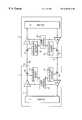
- an optical communication systemhaving two switching units 1 and 2 , each of which could comprise an optical add/drop multiplexer or a cross-connect switch 3 , 4 .
- the switching units 1 and 2are linked by two light guides which take the form of optical fibres 5 and 6 , and in practice the units 1 and 2 may be many kilometers apart. Instead, however, a repeater or simple add/drop unit may be positioned at one or both ends of the link shown.
- the units 1 and 2form part of a larger network which in practice, will contain many routing nodes, each of which may comprise a switching unit or an add/drop unit.
- the switch 3generates, by means of an optical multiplexer not separately shown, a number of separate optical channels at different optical carrier wavelengths each of which carries voice and/or data traffic. These channels are sent along a common light fibre 7 in wavelength division multiplex (WDM) format to an optical amplifier 8 which amplifies the optical signals by means of high power lasers to a high power level for transmission to the distant switching unit 2 via the optical fibre 5 .
- WDMwavelength division multiplex
- a relatively low power supervisory channel signalis generated at a supervisory insert unit 9 which includes a laser source and is added to the fibre 5 by optical coupler 30 , the supervisory signal having a different carrier wavelength to each of the traffic-carrying optical channels.
- the supervisory channelhas a much lower optical power than each of the traffic-carrying optical channels.
- the supervisory channelcarries relatively low frequency (eg.2 Mbit) path and routing information, and frame alignment signals, and only travels from one node to the next where it is regenerated, whereas the traffic-carrying channels carry high frequency signals, and may pass through several nodes before the data traffic is regenerated.
- the supervisory channelis extracted by optical coupler 31 and passed to extract unit 10 , whilst the traffic-carrying optical channels are passed to an amplifier 11 which compensates for any reduction of optical signal level due to attenuation by the fibre 5 .
- the amplified signalis passed to switch 4 , which is similar to switch 3 , where the optical channels are demultiplexed, switched and routed as necessary.
- the optical coupler 31is frequency selective and is operative to direct the supervisory optical channel to the extract unit 10 .
- the fibre 5carries a unidirectional signal from switching unit 1 to switching unit 2 .
- the similar optical fibre 6carries a unidirectional signal from switching unit 2 to switching unit 1 , and it has associated with it an amplifier 15 , supervisory insert unit 16 , optical couplers 32 and 33 , supervisory extract unit 17 and amplifier 18 in an analogous manner.
- the light signals generated by amplifiers 8 and 15are very intense laser beams, and care must be taken so that they do not harm personnel.
- a loss of signalis detected at the laser control unit 22 .
- laser control unit 22detects a loss of frame condition from the supervisory extract unit 10 and when both the loss of signal condition and loss of frame condition are detected at the laser control unit 22 , this unit shuts down the high power laser beams from amplifier . 15 and shuts down the laser in the supervisory insert unit 16 .
- Laser control unit 21detects that amplifier 15 has been shut down by detecting its loss of signal at amplifier 18 , and detects that supervisory unit 16 has been shut down by detecting the loss of frame condition, and in response shuts down amplifier 8 and the laser in the supervisory insert unit 9 .
- the break in the fibres 5 , 6 and any damage to themcan be safely repaired by personnel.
- the amplifiers 8 and 15are inhibited but the supervisory channel continues to be transmitted at its low level, and it is transmitted in a pulsed manner, so that its mean power level is further substantially reduced.
- the supervisory channelis pulsed on for about two seconds each minute, as such a pulse has sufficient duration to permit frame alignment to be recovered when its signal is received at the far end of a link.
- a frame period in a communication systemis 125 ⁇ s, but a frame alignment signal must be present for many frame periods to enable signal lock and synchronization between receiver and transmitter to be achieved.
- the frame alignment signal transmitted from switching unit 1will be received at the far end of the link when the fibre is repaired and this is used by laser control unit 22 to turn on the supervisory insert unit 16 .
- laser control unit 21When laser control unit 21 receives the supervisory channel, it acts to enable supervisory insert unit 9 .
- the amplifiers 8 and 15are enabled, and operation of the communication system recommences.
- the couplers 30 and 32are located downstream of the amplifiers 8 and 15 and as close to the output ports of switching units 1 and 2 as possible, so that even if a fault occurs in the switching units, particularly in the high power amplifiers, the supervisory channel is maintained.
- the supervisory insert unitincludes a modulated laser whose output is coupled directly without further amplification onto the respective optical fibre at the output ports of the switching unit 1 or 2 .
- This difficultyis overcome by transmitting over the supervisory channel an identifier signal which uniquely identifies a particular transmitter.
- receipt of an identifier signal which differs from that expected under normal operationwill cause the laser amplifiers to be shut down.
- the supervisory channelgenerates pulsed signals which are used to detect repair of the fibre, and to enable the high power optical amplifiers to be reset and enabled.
Landscapes
- Physics & Mathematics (AREA)
- Electromagnetism (AREA)
- Engineering & Computer Science (AREA)
- Computer Networks & Wireless Communication (AREA)
- Signal Processing (AREA)
- Optical Communication System (AREA)
Abstract
Description
Claims (16)
Applications Claiming Priority (2)
| Application Number | Priority Date | Filing Date | Title |
|---|---|---|---|
| GB9906394AGB2348063B (en) | 1999-03-19 | 1999-03-19 | Optical communication system |
| GB9906394 | 1999-03-19 |
Publications (1)
| Publication Number | Publication Date |
|---|---|
| US6483616B1true US6483616B1 (en) | 2002-11-19 |
Family
ID=10849990
Family Applications (1)
| Application Number | Title | Priority Date | Filing Date |
|---|---|---|---|
| US09/391,750Expired - LifetimeUS6483616B1 (en) | 1999-03-19 | 1999-09-08 | Safe repair of malfunction in optical communication system |
Country Status (8)
| Country | Link |
|---|---|
| US (1) | US6483616B1 (en) |
| EP (2) | EP1041747A3 (en) |
| JP (1) | JP4447105B2 (en) |
| CN (2) | CN1267981A (en) |
| AU (1) | AU2227200A (en) |
| GB (1) | GB2348063B (en) |
| NO (1) | NO20001260L (en) |
| RU (1) | RU2000106750A (en) |
Cited By (25)
| Publication number | Priority date | Publication date | Assignee | Title |
|---|---|---|---|---|
| US20020181037A1 (en)* | 2001-06-01 | 2002-12-05 | Richard Lauder | Failure protection switching in optical network |
| US20030002109A1 (en)* | 2001-06-29 | 2003-01-02 | Jim Hochberg | Eye safety shutdown |
| US20030011855A1 (en)* | 2001-07-16 | 2003-01-16 | Fujitsu Limited | Optical transmission system |
| US20030095303A1 (en)* | 2001-11-16 | 2003-05-22 | Cunningham David G. | Open fiber control for optical transceivers |
| US20030113118A1 (en)* | 2001-11-28 | 2003-06-19 | Meir Bartur | Smart single fiber optic transceiver |
| US6681079B1 (en)* | 2000-05-18 | 2004-01-20 | Nortel Networks Limited | Optical fibre monitoring system |
| US20040071392A1 (en)* | 2000-11-28 | 2004-04-15 | Lauder Andrew G | Optical shutter |
| US20040091263A1 (en)* | 2002-10-30 | 2004-05-13 | Fujitsu Limited | Wavelength-division multiplexing optical communication system |
| US20040208519A1 (en)* | 2002-03-07 | 2004-10-21 | Lucent Technologies Inc. | Method and apparatus for automatically controlling optical signal power in optical transmission systems |
| US20040213567A1 (en)* | 2003-03-06 | 2004-10-28 | Fujitsu Limited & Nippon Telegraph | Automatic power restoring method and optical communication system |
| US20050105900A1 (en)* | 2003-10-07 | 2005-05-19 | Pioneer Corporation | Optical transmission system |
| US20050169352A1 (en)* | 2002-04-12 | 2005-08-04 | Perdue Kenneth L. | Control circuit |
| US20060198016A1 (en)* | 2005-03-04 | 2006-09-07 | Optovia Corporation | Optical communications system with fiber break detection in the presence of raman amplification |
| US20070217794A1 (en)* | 2006-03-16 | 2007-09-20 | Fujitsu Limited | Method for measuring optical characteristics and system thereof |
| US20070242689A1 (en)* | 2006-04-14 | 2007-10-18 | Adc Telecommunications, Inc. | System and method for remotely restoring inoperative data communications |
| US20080075459A1 (en)* | 2005-06-03 | 2008-03-27 | Huawei Technologies Co., Ltd. | Method and optical amplifier for laser safety protection and method for loading identification signal |
| US20080205900A1 (en)* | 2007-02-28 | 2008-08-28 | Finisar Corporation | Status link for multi-channel optical communication systems |
| US20080267620A1 (en)* | 2007-04-30 | 2008-10-30 | Finisar Corporation | Eye safety and interoperability of active cable devices |
| US20080310837A1 (en)* | 2005-05-03 | 2008-12-18 | Martin Goetzer | Passive Optical Test Termination |
| US20090060520A1 (en)* | 2007-02-28 | 2009-03-05 | Finisar Corporation | Redundancy and interoperability in multi-channel optoelectronic devices |
| US20090136234A1 (en)* | 2007-11-28 | 2009-05-28 | Farrokh Mottahedin | Transceiver module sleep mode |
| US20090257748A1 (en)* | 2006-12-28 | 2009-10-15 | Fujitsu Limited | Optical transmission apparatus and optical transmission method |
| US20210409113A1 (en)* | 2018-11-13 | 2021-12-30 | Nippon Telegraph And Telephone Corporation | Optical transmission system and unused channel verification method |
| US20230130007A1 (en)* | 2021-10-27 | 2023-04-27 | Ii-Vi Delaware, Inc. | Eye Safety Interlock For Fiber-Coupled High Power Laser Sources |
| US11652545B2 (en)* | 2020-11-24 | 2023-05-16 | Ciena Corporation | Avoiding fiber damage on non-supervisory optical fiber links |
Families Citing this family (13)
| Publication number | Priority date | Publication date | Assignee | Title |
|---|---|---|---|---|
| JP3461475B2 (en) | 1999-09-08 | 2003-10-27 | 日本電気株式会社 | Optical wavelength division multiplexing transmission system and main signal bidirectional shutdown system used for it |
| SE519731C2 (en) | 2000-09-29 | 2003-04-01 | Transmode Systems Ab | A transmitter-receiver device, and a communication system with optical communication monitoring |
| SE517754C2 (en)* | 2000-11-15 | 2002-07-09 | Ericsson Telefon Ab L M | Device link and method for controlling communication links |
| US6845189B2 (en) | 2000-11-15 | 2005-01-18 | Telefonaktiebolaget Lm Ericsson (Publ) | System and a method for limiting the maximum of light transmitted from a ribbon fiber |
| JP3768110B2 (en)* | 2001-02-22 | 2006-04-19 | 富士通株式会社 | Optical amplifier |
| CN1305243C (en)* | 2003-05-09 | 2007-03-14 | 中兴通讯股份有限公司 | Testing method and apparatus for automatic light power reducing process time of dense wave divided multiplexing system |
| JP4337603B2 (en)* | 2004-03-31 | 2009-09-30 | 日本電気株式会社 | Optical transmission system |
| IL165958A (en)* | 2004-12-23 | 2010-12-30 | Eci Telecom Ltd | Method of controlling optical amplifier located along an optical link |
| CN101325650B (en)* | 2007-06-11 | 2010-04-14 | 青岛海信电器股份有限公司 | Sound-video receiving equipment capable of being compatible (with) a plurality of access modes |
| US9287991B2 (en) | 2012-10-17 | 2016-03-15 | Christie Digital Systems Usa, Inc. | Light module interlock system |
| EP2819322B1 (en)* | 2013-06-28 | 2018-04-04 | Deutsche Telekom AG | Automated error response for an optical transmission system |
| JP6638210B2 (en) | 2015-04-17 | 2020-01-29 | ソニー株式会社 | Communication device, communication method, and communication system |
| CN104993871B (en)* | 2015-05-28 | 2017-11-28 | 武汉光迅科技股份有限公司 | Light relay amplifier device in a kind of novel tower |
Citations (7)
| Publication number | Priority date | Publication date | Assignee | Title |
|---|---|---|---|---|
| US4833668A (en)* | 1986-07-10 | 1989-05-23 | British Telecommunications Public Limited Company | Fault detection in a full duplex optical communications system |
| EP0382243A2 (en) | 1989-02-09 | 1990-08-16 | Fujitsu Limited | Optical transmission line system |
| US4994675A (en) | 1989-04-28 | 1991-02-19 | Rebo Research, Inc. | Method and apparatus for checking continuity of optic transmission |
| EP0581138A1 (en) | 1992-07-30 | 1994-02-02 | Alcatel N.V. | Fail-safe automatic shut-down apparatus and method for high output power optical communications system |
| US5790293A (en)* | 1995-10-27 | 1998-08-04 | Lucent Technologies Inc. | Systems for monitoring optical path characteristics in an optical communication system |
| US6075628A (en)* | 1994-08-17 | 2000-06-13 | Nortel Networks Corporation | Fault location in optical communication systems |
| US6359708B1 (en)* | 1997-09-18 | 2002-03-19 | Lucent Technologies Inc. | Optical transmission line automatic power reduction system |
Family Cites Families (5)
| Publication number | Priority date | Publication date | Assignee | Title |
|---|---|---|---|---|
| US5136410A (en)* | 1990-01-09 | 1992-08-04 | Ibm Corporation | Optical fiber link control safety system |
| US5019769A (en)* | 1990-09-14 | 1991-05-28 | Finisar Corporation | Semiconductor laser diode controller and laser diode biasing control method |
| US5335104A (en)* | 1992-10-22 | 1994-08-02 | Laser Precision Corp. | Method of detecting breaks in multi-drop feeder systems |
| JP2682517B2 (en)* | 1995-07-26 | 1997-11-26 | 日本電気株式会社 | Light output blocking system |
| US6452701B1 (en)* | 1997-03-19 | 2002-09-17 | Fujitsu Limited | Wavelength division multiplexing communications network supervisory system |
- 1999
- 1999-03-19GBGB9906394Apatent/GB2348063B/ennot_activeExpired - Lifetime
- 1999-09-08USUS09/391,750patent/US6483616B1/ennot_activeExpired - Lifetime
- 2000
- 2000-02-07EPEP00300932Apatent/EP1041747A3/ennot_activeCeased
- 2000-02-07EPEP10181841.7Apatent/EP2271005B1/ennot_activeExpired - Lifetime
- 2000-03-10NONO20001260Apatent/NO20001260L/enunknown
- 2000-03-14AUAU22272/00Apatent/AU2227200A/ennot_activeAbandoned
- 2000-03-17CNCN00104322Apatent/CN1267981A/enactivePending
- 2000-03-17RURU2000106750/09Apatent/RU2000106750A/ennot_activeApplication Discontinuation
- 2000-03-17CNCN200910002832.6Apatent/CN101521542B/ennot_activeExpired - Lifetime
- 2000-03-21JPJP2000078316Apatent/JP4447105B2/ennot_activeExpired - Lifetime
Patent Citations (8)
| Publication number | Priority date | Publication date | Assignee | Title |
|---|---|---|---|---|
| US4833668A (en)* | 1986-07-10 | 1989-05-23 | British Telecommunications Public Limited Company | Fault detection in a full duplex optical communications system |
| EP0382243A2 (en) | 1989-02-09 | 1990-08-16 | Fujitsu Limited | Optical transmission line system |
| US4994675A (en) | 1989-04-28 | 1991-02-19 | Rebo Research, Inc. | Method and apparatus for checking continuity of optic transmission |
| EP0581138A1 (en) | 1992-07-30 | 1994-02-02 | Alcatel N.V. | Fail-safe automatic shut-down apparatus and method for high output power optical communications system |
| US5428471A (en)* | 1992-07-30 | 1995-06-27 | Alcatel Network Systems, Inc. | Fail-safe automatic shut-down apparatus and method for high output power optical communications system |
| US6075628A (en)* | 1994-08-17 | 2000-06-13 | Nortel Networks Corporation | Fault location in optical communication systems |
| US5790293A (en)* | 1995-10-27 | 1998-08-04 | Lucent Technologies Inc. | Systems for monitoring optical path characteristics in an optical communication system |
| US6359708B1 (en)* | 1997-09-18 | 2002-03-19 | Lucent Technologies Inc. | Optical transmission line automatic power reduction system |
Cited By (50)
| Publication number | Priority date | Publication date | Assignee | Title |
|---|---|---|---|---|
| US6681079B1 (en)* | 2000-05-18 | 2004-01-20 | Nortel Networks Limited | Optical fibre monitoring system |
| US20040071392A1 (en)* | 2000-11-28 | 2004-04-15 | Lauder Andrew G | Optical shutter |
| US7729613B2 (en)* | 2000-11-28 | 2010-06-01 | Ericsson Ab | Apparatus for optical path monitoring and an optical shutter for preventing signal transimission in a faulty optical path |
| US20020181037A1 (en)* | 2001-06-01 | 2002-12-05 | Richard Lauder | Failure protection switching in optical network |
| US20030002109A1 (en)* | 2001-06-29 | 2003-01-02 | Jim Hochberg | Eye safety shutdown |
| US20030011855A1 (en)* | 2001-07-16 | 2003-01-16 | Fujitsu Limited | Optical transmission system |
| US7103275B2 (en)* | 2001-07-16 | 2006-09-05 | Fujitsu Limited | Optical transmission system |
| US20030095303A1 (en)* | 2001-11-16 | 2003-05-22 | Cunningham David G. | Open fiber control for optical transceivers |
| US7092630B2 (en) | 2001-11-16 | 2006-08-15 | Avago Technologies Fiber Ip(Singapore) Ptd. Ltd. | Open fiber control for optical transceivers |
| WO2003046614A3 (en)* | 2001-11-28 | 2003-11-20 | Optical Zonu Corp | Smart single fiber optic transceiver |
| US20030113118A1 (en)* | 2001-11-28 | 2003-06-19 | Meir Bartur | Smart single fiber optic transceiver |
| US20040208519A1 (en)* | 2002-03-07 | 2004-10-21 | Lucent Technologies Inc. | Method and apparatus for automatically controlling optical signal power in optical transmission systems |
| US7957643B2 (en)* | 2002-03-07 | 2011-06-07 | Alcatel-Lucent Usa Inc. | Method and apparatus for automatically controlling optical signal power in optical transmission systems |
| US20050169352A1 (en)* | 2002-04-12 | 2005-08-04 | Perdue Kenneth L. | Control circuit |
| US7423549B2 (en)* | 2002-04-12 | 2008-09-09 | Thomson Licensing | Digital control circuit for serial UART transmissions |
| US7245421B2 (en)* | 2002-10-30 | 2007-07-17 | Fujitsu Limited | Wavelength-division multiplexing optical communication system |
| US20040091263A1 (en)* | 2002-10-30 | 2004-05-13 | Fujitsu Limited | Wavelength-division multiplexing optical communication system |
| US7792430B2 (en) | 2003-03-06 | 2010-09-07 | Fujitsu Limited | Automatic power restoring method and optical communication system |
| US20080317461A1 (en)* | 2003-03-06 | 2008-12-25 | Fujitsu Limited | Automatic power restoring method and optical communication system |
| US20090175616A1 (en)* | 2003-03-06 | 2009-07-09 | Fujitsu Limited | Automatic power restoring method and optical communication system |
| US7664392B2 (en) | 2003-03-06 | 2010-02-16 | Fujitsu Limited | Automatic power restoring method and optical communication system |
| US7437069B2 (en)* | 2003-03-06 | 2008-10-14 | Fujitsu Limited | Automatic power restoring method and optical communication system |
| US20040213567A1 (en)* | 2003-03-06 | 2004-10-28 | Fujitsu Limited & Nippon Telegraph | Automatic power restoring method and optical communication system |
| US20050105900A1 (en)* | 2003-10-07 | 2005-05-19 | Pioneer Corporation | Optical transmission system |
| US20060198016A1 (en)* | 2005-03-04 | 2006-09-07 | Optovia Corporation | Optical communications system with fiber break detection in the presence of raman amplification |
| US7218442B2 (en)* | 2005-03-04 | 2007-05-15 | Jds Uniphase Corporation | Optical communications system with fiber break detection in the presence of Raman amplification |
| EP2413519A1 (en)* | 2005-05-03 | 2012-02-01 | Ericsson AB | Passive optical test termination |
| US20080310837A1 (en)* | 2005-05-03 | 2008-12-18 | Martin Goetzer | Passive Optical Test Termination |
| US8331777B2 (en) | 2005-05-03 | 2012-12-11 | Ericsson Ab | Passive optical test termination |
| US8036538B2 (en) | 2005-06-03 | 2011-10-11 | Huawei Technologies Co., Ltd. | Method and optical amplifier for laser safety protection and method for loading identification signal |
| US20080075459A1 (en)* | 2005-06-03 | 2008-03-27 | Huawei Technologies Co., Ltd. | Method and optical amplifier for laser safety protection and method for loading identification signal |
| US7756422B2 (en)* | 2006-03-16 | 2010-07-13 | Fujitsu Limited | Method for measuring optical characteristics and system thereof |
| US20070217794A1 (en)* | 2006-03-16 | 2007-09-20 | Fujitsu Limited | Method for measuring optical characteristics and system thereof |
| US7630296B2 (en)* | 2006-04-14 | 2009-12-08 | Adc Telecommunications, Inc. | System and method for remotely restoring inoperative data communications |
| US20070242689A1 (en)* | 2006-04-14 | 2007-10-18 | Adc Telecommunications, Inc. | System and method for remotely restoring inoperative data communications |
| US20090257748A1 (en)* | 2006-12-28 | 2009-10-15 | Fujitsu Limited | Optical transmission apparatus and optical transmission method |
| US20080205900A1 (en)* | 2007-02-28 | 2008-08-28 | Finisar Corporation | Status link for multi-channel optical communication systems |
| US8032021B2 (en)* | 2007-02-28 | 2011-10-04 | Finisar Corporation | Status link for multi-channel optical communication systems |
| US8861952B2 (en)* | 2007-02-28 | 2014-10-14 | Finisar Corporation | Redundancy and interoperability in multi-channel optoelectronic devices |
| US20120020674A1 (en)* | 2007-02-28 | 2012-01-26 | Finisar Corporation | Status link for multi-channel optical communication systems |
| US20090060520A1 (en)* | 2007-02-28 | 2009-03-05 | Finisar Corporation | Redundancy and interoperability in multi-channel optoelectronic devices |
| US8526810B2 (en) | 2007-04-30 | 2013-09-03 | Finisar Corporation | Eye safety and interoperability of active cable devices |
| US20080267620A1 (en)* | 2007-04-30 | 2008-10-30 | Finisar Corporation | Eye safety and interoperability of active cable devices |
| US8509624B2 (en)* | 2007-11-28 | 2013-08-13 | Cisco Technology, Inc. | Transceiver module sleep mode |
| US20090136234A1 (en)* | 2007-11-28 | 2009-05-28 | Farrokh Mottahedin | Transceiver module sleep mode |
| US20210409113A1 (en)* | 2018-11-13 | 2021-12-30 | Nippon Telegraph And Telephone Corporation | Optical transmission system and unused channel verification method |
| US11595120B2 (en)* | 2018-11-13 | 2023-02-28 | Nippon Telegraph And Telephone Corporation | Optical transmission system and unused channel verification method |
| US11652545B2 (en)* | 2020-11-24 | 2023-05-16 | Ciena Corporation | Avoiding fiber damage on non-supervisory optical fiber links |
| US20230130007A1 (en)* | 2021-10-27 | 2023-04-27 | Ii-Vi Delaware, Inc. | Eye Safety Interlock For Fiber-Coupled High Power Laser Sources |
| US12345595B2 (en)* | 2021-10-27 | 2025-07-01 | Ii-Vi Delaware, Inc. | Eye safety interlock for fiber-coupled high power laser sources |
Also Published As
| Publication number | Publication date |
|---|---|
| AU2227200A (en) | 2000-09-21 |
| JP2000286798A (en) | 2000-10-13 |
| EP1041747A3 (en) | 2003-08-13 |
| GB2348063B (en) | 2001-03-07 |
| GB9906394D0 (en) | 1999-05-12 |
| JP4447105B2 (en) | 2010-04-07 |
| NO20001260L (en) | 2000-09-13 |
| RU2000106750A (en) | 2002-01-20 |
| CN1267981A (en) | 2000-09-27 |
| NO20001260D0 (en) | 2000-03-10 |
| CN101521542B (en) | 2016-01-06 |
| CN101521542A (en) | 2009-09-02 |
| EP1041747A2 (en) | 2000-10-04 |
| EP2271005A1 (en) | 2011-01-05 |
| HK1029675A1 (en) | 2001-04-06 |
| GB2348063A (en) | 2000-09-20 |
| EP2271005B1 (en) | 2018-04-11 |
Similar Documents
| Publication | Publication Date | Title |
|---|---|---|
| US6483616B1 (en) | Safe repair of malfunction in optical communication system | |
| EP1025432B1 (en) | Interlocked high power fiber system using otdr | |
| US6108112A (en) | Method and apparatus for failure recovery in passive optical network | |
| US7415211B2 (en) | Interconnections and protection between optical communications networks | |
| US6259554B1 (en) | Optical amplifier repeater system | |
| US7231146B2 (en) | Optical communication system | |
| KR19990029977A (en) | Optical transmission line automatic power cut off system | |
| US7697845B2 (en) | Optical transmission equipment and optical add-drop multiplexer | |
| JP2011077808A (en) | Optical transmission system | |
| KR20010075159A (en) | Method and system for detecting loss of signal in wavelength division multiplexed systems | |
| JP2682517B2 (en) | Light output blocking system | |
| EP1839402B1 (en) | Method of controlling optical amplifier located along an optical link | |
| US6229643B1 (en) | Optical fiber amplifier surge protective apparatus | |
| JPH09274206A (en) | Optical amplifier device and linear repeating optical amplification and transmission device | |
| JP3557025B2 (en) | Direction switching optical amplifier and bus-type single-core optical communication system using the amplifier | |
| JP4225035B2 (en) | Optical amplification repeater transmission system and monitoring control method thereof | |
| JPH04137833A (en) | optical relay system | |
| KR100467319B1 (en) | Wavelength division multiplexing system and method for suppressing unwanted alarm and shutting down laser | |
| KR100528968B1 (en) | Apparatus and method for maintaining optical transmission system | |
| EP0961514A1 (en) | Optical communication system | |
| JP2000106541A (en) | Optical communication system | |
| JPH0730486A (en) | Optical repeater system |
Legal Events
| Date | Code | Title | Description |
|---|---|---|---|
| AS | Assignment | Owner name:MARCONI COMMUNICATION LTD, UNITED KINGDOM Free format text:ASSIGNMENT OF ASSIGNORS INTEREST;ASSIGNOR:MADDOCKS, DAVID JOHN;REEL/FRAME:010383/0766 Effective date:19990915 Owner name:MARCONI COMMUNICATIONS LIMITED, UNITED KINGDOM Free format text:ASSIGNMENT OF ASSIGNORS INTEREST;ASSIGNOR:CALLAN, PAUL ALEXANDER;REEL/FRAME:010383/0769 Effective date:19990915 | |
| STCF | Information on status: patent grant | Free format text:PATENTED CASE | |
| AS | Assignment | Owner name:MARCONI UK INTELLECTUAL PROPERTY LTD., ENGLAND Free format text:ASSIGNMENT OF ASSIGNORS INTEREST;ASSIGNOR:MARCONI COMMUNICATIONS LIMITED;REEL/FRAME:014624/0723 Effective date:20030519 | |
| FPAY | Fee payment | Year of fee payment:4 | |
| AS | Assignment | Owner name:M(DGP1) LTD,UNITED KINGDOM Free format text:ASSIGNMENT OF ASSIGNORS INTEREST;ASSIGNOR:MARCONI UK INTELLECTUAL PROPERTY LTD.;REEL/FRAME:018635/0425 Effective date:20051223 Owner name:ERICSSON AB,SWEDEN Free format text:ASSIGNMENT OF ASSIGNORS INTEREST;ASSIGNOR:M(DGP1) LTD;REEL/FRAME:018797/0607 Effective date:20060101 Owner name:M(DGP1) LTD, UNITED KINGDOM Free format text:ASSIGNMENT OF ASSIGNORS INTEREST;ASSIGNOR:MARCONI UK INTELLECTUAL PROPERTY LTD.;REEL/FRAME:018635/0425 Effective date:20051223 Owner name:ERICSSON AB, SWEDEN Free format text:ASSIGNMENT OF ASSIGNORS INTEREST;ASSIGNOR:M(DGP1) LTD;REEL/FRAME:018797/0607 Effective date:20060101 | |
| FPAY | Fee payment | Year of fee payment:8 | |
| FPAY | Fee payment | Year of fee payment:12 |